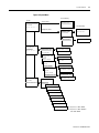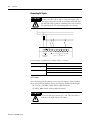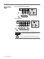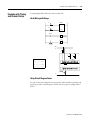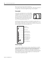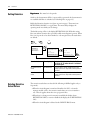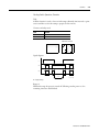
1
Pico™ Controller
(Catalog Numbers 1760-L12AWA,
-L12AWA-NC, -L12AWA-ND,
-L12BWB, -L12BWB-NC, and
-L18AWA)
User Manual
Important User
Information
Because of the variety of uses for the products described in this publication, those
responsible for the application and use of this control equipment must satisfy
themselves that all necessary steps have been taken to assure that each application
and use meets all performance and safety requirements, including any applicable
laws, regulations, codes and standards.
The illustrations, charts, sample programs and layout examples shown in this
guide are intended solely for purposes of example. Since there are many variables
and requirements associated with any particular installation, Rockwell
International Corporation does not assume responsibility or liability (to include
intellectual property liability) for actual use based upon the examples shown in
this publication.
Rockwell Automation publication SGI-1.1, Safety Guidelines for the Application,
Installation and Maintenance of Solid-State Control (available from your local
Rockwell Automation office), describes some important differences between
solid-state equipment and electromechanical devices that should be taken into
consideration when applying products such as those described in this publication.
Reproduction of the contents of this copyrighted publication, in whole or part,
without written permission of Rockwell Automation, is prohibited.
Throughout this manual we use notes to make you aware of safety considerations:
ATTENTION
!
Identifies information about practices or circumstances that can
lead to personal injury or death, property damage or economic
loss
Attention statements help you to:
• identify a hazard
• avoid a hazard
• recognize the consequences
IMPORTANT Identifies information that is critical for successful application
and understanding of the product.
Pico is a trademarks of Rockwell Automation.
Table of Contents
Preface
Who Should Use this Manual . . . . . . . . . . . . . . . . . . . . . . . . . . . . .
Purpose of this Manual . . . . . . . . . . . . . . . . . . . . . . . . . . . . . . . . . .
Related Documentation . . . . . . . . . . . . . . . . . . . . . . . . . . . . . .
Common Techniques Used in this Manual . . . . . . . . . . . . . . . . . . .
Rockwell Automation Support . . . . . . . . . . . . . . . . . . . . . . . . . . . .
Local Product Support . . . . . . . . . . . . . . . . . . . . . . . . . . . . . . .
Technical Product Assistance. . . . . . . . . . . . . . . . . . . . . . . . . . .
Your Questions or Comments on this Manual . . . . . . . . . . . . .
P-1
P-1
P-1
P-2
P-2
P-2
P-2
P-2
Chapter 1
System Overview
Overview. . . . . . . . . . . . . . . . . . . . . . . . . . . . . . . . . . . . . . . . . . . . .
Hardware Versions . . . . . . . . . . . . . . . . . . . . . . . . . . . . . . . . . . . . .
Operating Principles . . . . . . . . . . . . . . . . . . . . . . . . . . . . . . . . . . . .
Operating Buttons . . . . . . . . . . . . . . . . . . . . . . . . . . . . . . . . . .
Using Menus to Choose Values. . . . . . . . . . . . . . . . . . . . . . . . .
Selecting the Main and System Menus . . . . . . . . . . . . . . . . . . .
Menu Structure . . . . . . . . . . . . . . . . . . . . . . . . . . . . . . . . . . . . .
Selecting or Toggling Between Menu Items . . . . . . . . . . . . . . .
Cursor Display . . . . . . . . . . . . . . . . . . . . . . . . . . . . . . . . . . . . .
Setting Values . . . . . . . . . . . . . . . . . . . . . . . . . . . . . . . . . . . . . .
1-1
1-2
1-3
1-3
1-3
1-4
1-5
1-8
1-8
1-8
Chapter 2
Installation
i
Prevent Electrical Shock . . . . . . . . . . . . . . . . . . . . . . . . . . . . . . . . . 2-1
European Communities (EC) Directive Compliance. . . . . . . . . . . . 2-1
EMC Directive . . . . . . . . . . . . . . . . . . . . . . . . . . . . . . . . . . . . . 2-1
Low Voltage Directive. . . . . . . . . . . . . . . . . . . . . . . . . . . . . . . . 2-1
Mounting . . . . . . . . . . . . . . . . . . . . . . . . . . . . . . . . . . . . . . . . . . . . 2-2
Minimum Spacing . . . . . . . . . . . . . . . . . . . . . . . . . . . . . . . . . . 2-2
DIN Rail Mounting . . . . . . . . . . . . . . . . . . . . . . . . . . . . . . . . . 2-2
Using a Mounting Plate . . . . . . . . . . . . . . . . . . . . . . . . . . . . . . 2-3
Wiring Terminals . . . . . . . . . . . . . . . . . . . . . . . . . . . . . . . . . . . . . . 2-3
Required Tools . . . . . . . . . . . . . . . . . . . . . . . . . . . . . . . . . . . . . 2-3
Wire Size. . . . . . . . . . . . . . . . . . . . . . . . . . . . . . . . . . . . . . . . . . 2-3
Connecting the Incoming Power. . . . . . . . . . . . . . . . . . . . . . . . . . . 2-4
Using Surge Suppressors . . . . . . . . . . . . . . . . . . . . . . . . . . . . . . . . . 2-5
Recommended Surge Suppressors . . . . . . . . . . . . . . . . . . . . . . . 2-7
Connecting the Inputs . . . . . . . . . . . . . . . . . . . . . . . . . . . . . . . . . . 2-7
Connecting AC Inputs . . . . . . . . . . . . . . . . . . . . . . . . . . . . . . . 2-8
Connecting DC Inputs . . . . . . . . . . . . . . . . . . . . . . . . . . . . . . 2-10
Connecting Analog Inputs . . . . . . . . . . . . . . . . . . . . . . . . . . . 2-10
Connecting Outputs . . . . . . . . . . . . . . . . . . . . . . . . . . . . . . . . . . . 2-13
Connecting Relay Outputs . . . . . . . . . . . . . . . . . . . . . . . . . . . . . . 2-14
Publication 1760-UM001A-EN-P
Table of Contents
ii
Chapter 3
Commissioning
Powering On Unit . . . . . . . . . . . . . . . . . . . . . . . . . . . . . . . . . . . . .
Setting the Menu Language . . . . . . . . . . . . . . . . . . . . . . . . . . . . . .
Operating Modes . . . . . . . . . . . . . . . . . . . . . . . . . . . . . . . . . . . . . .
Creating a Circuit Diagram (Program) . . . . . . . . . . . . . . . . . . . . . .
Starting Point: Status Display . . . . . . . . . . . . . . . . . . . . . . . . . .
Circuit Diagram Display. . . . . . . . . . . . . . . . . . . . . . . . . . . . . .
From the First Contact to the Output Coil. . . . . . . . . . . . . . . .
Wiring Inside of Your Program. . . . . . . . . . . . . . . . . . . . . . . . .
Testing the Circuit Diagram . . . . . . . . . . . . . . . . . . . . . . . . . .
Power Flow Display . . . . . . . . . . . . . . . . . . . . . . . . . . . . . . . . .
Deleting a Circuit Diagram. . . . . . . . . . . . . . . . . . . . . . . . . . . .
Fast Circuit Diagram Entry. . . . . . . . . . . . . . . . . . . . . . . . . . . .
3-1
3-1
3-2
3-3
3-4
3-4
3-5
3-6
3-7
3-7
3-8
3-8
Chapter 4
Drawing a Circuit Diagram
with Pico
Publication 1760-UM001A-EN-P
Pico Operation . . . . . . . . . . . . . . . . . . . . . . . . . . . . . . . . . . . . . . . . 4-1
Buttons for Drawing Circuit Diagrams . . . . . . . . . . . . . . . . . . . 4-1
Button Operation . . . . . . . . . . . . . . . . . . . . . . . . . . . . . . . . . . . 4-2
Contacts . . . . . . . . . . . . . . . . . . . . . . . . . . . . . . . . . . . . . . . . . . 4-3
Relays . . . . . . . . . . . . . . . . . . . . . . . . . . . . . . . . . . . . . . . . . . . 4-4
Circuit Diagram Display. . . . . . . . . . . . . . . . . . . . . . . . . . . . . . 4-4
Saving and Loading Circuit Diagrams. . . . . . . . . . . . . . . . . . . . 4-5
Working with Contacts and Relays . . . . . . . . . . . . . . . . . . . . . . . . . 4-6
Creating and Modifying Connections. . . . . . . . . . . . . . . . . . . . 4-8
Inserting and Deleting a Circuit Connection . . . . . . . . . . . . . . 4-9
Using the Cursor Buttons as Inputs . . . . . . . . . . . . . . . . . . . . . 4-9
Checking the Circuit Diagram . . . . . . . . . . . . . . . . . . . . . . . . 4-10
Coil Functions . . . . . . . . . . . . . . . . . . . . . . . . . . . . . . . . . . . . 4-11
Function Relay Types . . . . . . . . . . . . . . . . . . . . . . . . . . . . . . . . . . 4-14
Example with Timing and Counter Relays . . . . . . . . . . . . . . . . . . 4-15
Hard-Wiring with Relays . . . . . . . . . . . . . . . . . . . . . . . . . . . . 4-15
Using Circuit Diagram Forms. . . . . . . . . . . . . . . . . . . . . . . . . 4-15
Protecting Timer and Counter Settings. . . . . . . . . . . . . . . . . . 4-19
Timing Relays. . . . . . . . . . . . . . . . . . . . . . . . . . . . . . . . . . . . . . . . 4-19
Programming a Timing Relay. . . . . . . . . . . . . . . . . . . . . . . . . 4-19
Parameters for Timers. . . . . . . . . . . . . . . . . . . . . . . . . . . . . . . 4-20
Counter Relays . . . . . . . . . . . . . . . . . . . . . . . . . . . . . . . . . . . . . . 4-24
Time Switch . . . . . . . . . . . . . . . . . . . . . . . . . . . . . . . . . . . . . . . . . 4-27
Analog Comparators . . . . . . . . . . . . . . . . . . . . . . . . . . . . . . . . . . . 4-31
Text Display . . . . . . . . . . . . . . . . . . . . . . . . . . . . . . . . . . . . . . . . . 4-34
Circuit Diagram Elements Text Display . . . . . . . . . . . . . . . . . 4-35
Jumps . . . . . . . . . . . . . . . . . . . . . . . . . . . . . . . . . . . . . . . . . . . . . . 4-37
Circuit Diagram Symbols for Jumps . . . . . . . . . . . . . . . . . . . . 4-37
Power Flow Display . . . . . . . . . . . . . . . . . . . . . . . . . . . . . . . . 4-38
Example Programs . . . . . . . . . . . . . . . . . . . . . . . . . . . . . . . . . . . . 4-39
Table of Contents
Negation . . . . . . . . . . . . . . . . . . . . . . . . . . . . . . . . . . . . . . . . .
Permanent Contact (Unconditional Rung) . . . . . . . . . . . . . . .
Series Connection . . . . . . . . . . . . . . . . . . . . . . . . . . . . . . . . . .
Parallel Connection . . . . . . . . . . . . . . . . . . . . . . . . . . . . . . . . .
Exclusive OR Circuit . . . . . . . . . . . . . . . . . . . . . . . . . . . . . . .
Motor Start/Stop Circuit. . . . . . . . . . . . . . . . . . . . . . . . . . . . .
Flip-Flop Relay . . . . . . . . . . . . . . . . . . . . . . . . . . . . . . . . . . . .
On-Delayed Timing Relay . . . . . . . . . . . . . . . . . . . . . . . . . . .
Count Up Counter . . . . . . . . . . . . . . . . . . . . . . . . . . . . . . . . .
4x Shift Register . . . . . . . . . . . . . . . . . . . . . . . . . . . . . . . . . . .
Running Light. . . . . . . . . . . . . . . . . . . . . . . . . . . . . . . . . . . . .
Stairwell Lighting . . . . . . . . . . . . . . . . . . . . . . . . . . . . . . . . . .
iii
4-39
4-39
4-39
4-40
4-40
4-41
4-42
4-42
4-43
4-43
4-46
4-46
Chapter 5
Saving and Loading Circuit
Diagrams
Interface to Memory Module and Programming Cable . . . . . . . . .
Memory Module . . . . . . . . . . . . . . . . . . . . . . . . . . . . . . . . . . . . . . .
PicoSoft. . . . . . . . . . . . . . . . . . . . . . . . . . . . . . . . . . . . . . . . . . . . . .
Connecting Pico to the PC . . . . . . . . . . . . . . . . . . . . . . . . . . . .
If You Have Trouble . . . . . . . . . . . . . . . . . . . . . . . . . . . . . . . . .
5-1
5-2
5-4
5-5
5-5
Chapter 6
Pico System Settings
Password Protection . . . . . . . . . . . . . . . . . . . . . . . . . . . . . . . . . . . . 6-1
Setting the Password . . . . . . . . . . . . . . . . . . . . . . . . . . . . . . . . . 6-2
Activating the Password. . . . . . . . . . . . . . . . . . . . . . . . . . . . . . . 6-2
Unlocking Pico . . . . . . . . . . . . . . . . . . . . . . . . . . . . . . . . . . . . 6-3
Changing or Deleting a Password . . . . . . . . . . . . . . . . . . . . . . . 6-4
Changing the Menu Language . . . . . . . . . . . . . . . . . . . . . . . . . . . . 6-5
Changing Parameters . . . . . . . . . . . . . . . . . . . . . . . . . . . . . . . . . . . 6-5
Example: Modifying Switching Times for Outside Lighting . . . 6-7
Setting the Time . . . . . . . . . . . . . . . . . . . . . . . . . . . . . . . . . . . . . . . 6-8
Changing Between Winter/Summer Time (Daylight Saving Time) 6-8
Activating Debounce (Input Delay) . . . . . . . . . . . . . . . . . . . . . . . . 6-9
Activating and Deactivating P-Buttons . . . . . . . . . . . . . . . . . . . . . 6-10
Activating the P-Buttons . . . . . . . . . . . . . . . . . . . . . . . . . . . . . 6-10
Deactivating the P-Buttons . . . . . . . . . . . . . . . . . . . . . . . . . . . 6-10
Start-Up Behavior . . . . . . . . . . . . . . . . . . . . . . . . . . . . . . . . . . . . . 6-11
Setting the Start-Up Behavior . . . . . . . . . . . . . . . . . . . . . . . . . 6-11
Behavior When the Circuit Diagram is Deleted . . . . . . . . . . . . . . 6-11
Behavior During Uploading and Downloading . . . . . . . . . . . . . . . 6-11
Possible Faults . . . . . . . . . . . . . . . . . . . . . . . . . . . . . . . . . . . . . . . . 6-12
Publication 1760-UM001A-EN-P
Table of Contents
iv
Chapter 7
Retention
What is Retention? . . . . . . . . . . . . . . . . . . . . . . . . . . . . . . . . . . . . . 7-1
Pico Models with Data Retention . . . . . . . . . . . . . . . . . . . . . . . 7-1
Retentive Markers and Function Relays . . . . . . . . . . . . . . . . . . 7-1
Setting Retention . . . . . . . . . . . . . . . . . . . . . . . . . . . . . . . . . . . . . . 7-2
Deleting Retentive Actual Values . . . . . . . . . . . . . . . . . . . . . . . . . . 7-2
Transfer Retentive Behavior . . . . . . . . . . . . . . . . . . . . . . . . . . . . . . 7-3
Circuit Diagram Transfer (Behavior) . . . . . . . . . . . . . . . . . . . . 7-3
Changing the Operating Mode or the Circuit Diagram . . . . . . 7-3
Changing the Start-Up Behavior in the SYSTEM Menu. . . . . . 7-3
Retentive Auxiliary Relays (Markers). . . . . . . . . . . . . . . . . . . . . . . . 7-4
How the Retention Works . . . . . . . . . . . . . . . . . . . . . . . . . . . . 7-4
Examples. . . . . . . . . . . . . . . . . . . . . . . . . . . . . . . . . . . . . . . . . . 7-4
Retentive Timing Relays . . . . . . . . . . . . . . . . . . . . . . . . . . . . . . . . . 7-8
Use of Retention. . . . . . . . . . . . . . . . . . . . . . . . . . . . . . . . . . . . 7-8
Examples. . . . . . . . . . . . . . . . . . . . . . . . . . . . . . . . . . . . . . . . . . 7-9
Retentive Up/Down Counters C7, C8 . . . . . . . . . . . . . . . . . . . . . 7-14
How the Retention Works . . . . . . . . . . . . . . . . . . . . . . . . . . . 7-14
Examples. . . . . . . . . . . . . . . . . . . . . . . . . . . . . . . . . . . . . . . . . 7-14
Chapter 8
Inside Pico
Circuit Diagram Cycle . . . . . . . . . . . . . . . . . . . . . . . . . . . . . . . . . .
How Does This Affect Creation of the Circuit Diagram? . . . . .
Determining Cycle Time of Circuit Diagrams . . . . . . . . . . . . . . . .
1760-L12xxx Cycle Time . . . . . . . . . . . . . . . . . . . . . . . . . . . . .
1760-L18AWA Cycle Time . . . . . . . . . . . . . . . . . . . . . . . . . . .
Delay Times for Inputs and Outputs . . . . . . . . . . . . . . . . . . . . . . .
Delay Times for Pico DC Units (1760-L12BWB and
1760-L12BWB-NC). . . . . . . . . . . . . . . . . . . . . . . . . . . . . . . . .
Delay times for Pico AC Units (1760-AWA, -L12AWA-NC,
-L12AWA-ND, -L18AWA) . . . . . . . . . . . . . . . . . . . . . . . . . . .
8-1
8-2
8-3
8-3
8-5
8-7
8-7
8-8
Chapter 9
Troubleshooting
Messages from the Pico System . . . . . . . . . . . . . . . . . . . . . . . . . . . . 9-1
Possible Situations When Creating Circuit Diagrams . . . . . . . . . . . 9-2
Event . . . . . . . . . . . . . . . . . . . . . . . . . . . . . . . . . . . . . . . . . . . . . . . 9-3
Chapter 10
DC Simulator
Publication 1760-UM001A-EN-P
Description. . . . . . . . . . . . . . . . . . . . . . . . . . . . . . . . . . . . . . . . . . 10-1
Installation Guidelines . . . . . . . . . . . . . . . . . . . . . . . . . . . . . . . . . 10-2
Table of Contents
v
Appendix A
Specifications
Physical Specifications. . . . . . . . . . . . . . . . . . . . . . . . . . . . . . . . . . . A-1
Environmental Specifications . . . . . . . . . . . . . . . . . . . . . . . . . . . . . A-1
Electrical Specifications . . . . . . . . . . . . . . . . . . . . . . . . . . . . . . . . . . A-2
Power Supply . . . . . . . . . . . . . . . . . . . . . . . . . . . . . . . . . . . . . . . . . A-3
1760-L12AWA, -L12AWA-NC, -L12AWA-ND,
and 1760-L18AWA. . . . . . . . . . . . . . . . . . . . . . . . . . . . . . . . . . A-3
1760-L12BWB, and -L12BWB-NC . . . . . . . . . . . . . . . . . . . . . A-3
Inputs . . . . . . . . . . . . . . . . . . . . . . . . . . . . . . . . . . . . . . . . . . . . . . . A-3
1760-L12AWA, -L12AWA-NC, L12AWA-ND,
and 1760-L18AWA. . . . . . . . . . . . . . . . . . . . . . . . . . . . . . . . . . A-3
1760-L12BWB and -L12BWB-NC . . . . . . . . . . . . . . . . . . . . . A-4
Relay Outputs . . . . . . . . . . . . . . . . . . . . . . . . . . . . . . . . . . . . . . . . . A-5
Pico 1760-L12xx, and1760-L18AWA . . . . . . . . . . . . . . . . . . . . A-5
Cycle Time . . . . . . . . . . . . . . . . . . . . . . . . . . . . . . . . . . . . . . . . . . . A-7
1760-L12AWA, -L12AWA-NC, -L12AWA-ND,
-L12BWB, and -L12BWB-NC . . . . . . . . . . . . . . . . . . . . . . . . . A-7
1760-L18AWA . . . . . . . . . . . . . . . . . . . . . . . . . . . . . . . . . . . . . A-7
Dimensions . . . . . . . . . . . . . . . . . . . . . . . . . . . . . . . . . . . . . . . . . . . A-8
1760-L12AWA, -L12AWA-NC, -L12AWA-ND,
-L12BWB, and -L12BWB-NC . . . . . . . . . . . . . . . . . . . . . . . . . A-8
1760-L18AWA . . . . . . . . . . . . . . . . . . . . . . . . . . . . . . . . . . . . . A-8
Appendix B
Circuit Diagram Form
Glossary
Index
Publication 1760-UM001A-EN-P
Table of Contents
vi
Publication 1760-UM001A-EN-P
Preface
Read this preface to familiarize yourself with the rest of the manual. It provides
information concerning:
• who should use this manual
• the purpose of this manual
• related documentation
• conventions used in this manual
• Rockwell Automation support
Who Should Use this
Manual
Use this manual if you are responsible for designing, installing, programming, or
troubleshooting control systems that use Pico controllers.
You should have a basic understanding of electrical circuitry and familiarity with
relay logic. If you do not, obtain the proper training before using this product.
Purpose of this Manual
This manual is a reference guide for Pico controllers. It describes the procedures
you use to install, wire, and troubleshoot Pico.
Refer to publication 1760-GR001A-EN-P, Pico Controller Getting Results Manual
for a basic overview of Pico and an introduction to Pico programming.
Related Documentation
The following documents contain additional information concerning Rockwell
Automation products. To obtain a copy, contact your local Rockwell Automation
office or distributor.
For
Read this Document
Document Number
A basic overview of Pico and an introduction to Pico programming.
Pico Controller Getting Results
Manual
1760-GR001A-EN-P
In-depth information on grounding and wiring Allen-Bradley
programmable controllers
Allen-Bradley Programmable
Controller Grounding and Wiring
Guidelines
1770-4.1
A description of important differences between solid-state
programmable controller products and hard-wired electromechanical
devices
Application Considerations for
Solid-State Controls
SGI-1.1
An article on wire sizes and types for grounding electrical equipment
National Electrical Code - Published by the National Fire
Protection Association of Boston, MA.
A complete listing of current documentation, including ordering
instructions. Also indicates whether the documents are available on
CD-ROM or in multi-languages.
Allen-Bradley Publication Index
SD499
A glossary of industrial automation terms and abbreviations
Allen-Bradley Industrial Automation
Glossary
AG-7.1
P-1
Publication 1760-UM001A-EN-P
Preface
P-2
Common Techniques
Used in this Manual
The following conventions are used throughout this manual:
• Bulleted lists such as this one provide information, not procedural steps.
• Numbered lists provide sequential steps or hierarchical information.
• Italic type is used for emphasis.
Rockwell Automation
Support
Rockwell Automation offers support services worldwide, with over 75 Sales/
Support Offices, 512 authorized Distributors and 260 authorized Systems
Integrators located throughout the United States alone, plus Rockwell Automation
representatives in every major country in the world.
Local Product Support
Contact your local Rockwell Automation representative for:
• sales and order support
• product technical training
• warranty support
• support service agreements
Technical Product Assistance
If you need to contact Rockwell Automation for technical assistance, please review
the Troubleshooting appendix on page 9-1 in this manual first. Then call your local
Rockwell Automation representative.
You can also contact Rockwell Automation Technical Support at:
• http://www.ab.com.support
• [email protected]
• 440-646-6800 - Technical Support Line
Your Questions or Comments on this Manual
If you find a problem with this manual, or you have any suggestions for how this
manual could be made more useful to you, please contact us at the address below:
Rockwell Automation
Control and Information Group
Technical Communication, Dept. A602V
P.O. Box 2086
Milwaukee, WI 53201-2086
or visit our internet page at:
http://www.ab.com/pico or http://www.rockwellautomation.com
Publication 1760-UM001A-EN-P
Chapter
1
System Overview
Overview
Pico is an electronic control relay with built-in logic, timer, counter, and real-time
clock functions. Pico is a control and input device rolled into one that can perform
many different tasks in building and machine applications.
Pico is programmed using ladder diagrams, and each programming element is
entered directly via the Pico display. For example, you can:
• Connect make and break contacts in series and in parallel
• Connect output relays and markers
• Define outputs as relays, flip-flop relays or latching relays
• Select timing relays with different functions
• Assign eight up and down counters
• Display text with variables (1760-L18AWA only)
• Track the flow of current in the program
• Load, save and password-protect programs
Most controllers also offer a real-time clock, allowing up to 32 separate on and off
times.
The dc versions can receive analog signals at two inputs and evaluate the signals
with eight analog comparators.
If you prefer to program Pico from a PC, use PicoSoft programming software.
PicoSoft allows you to create and test your programs on the PC. It also enables you
to print out your programs in DIN, ANSI or Pico format.
1
Publication 1760-UM001A-EN-P
1-2
System Overview
Hardware Versions
1
7
2
Del
Alt
3
4
8
Esc
7
Del
Ok
5
Alt
8
Esc
6
Ok
5
8
3
5
Item
1
2
3
4
5
6
7
8
Description
Incoming Power
Inputs
Status LED
Buttons
Socket for memory module or PC interface cable
Outputs
LCD display
Write-On Surface
Pico controllers are available for both 120/240V ac and 24V dc operation and
come in both 12-I/O and 18-I/O sizes. Pico is available with and without a
real-time clock, and a version is available without a display and keypad. See the
following table for details.
Catalog Number Inputs
Real Time
Clock
1760-L12AWA
8 (120/240V ac) 4 (relay) 120/240V ac Yes
1760-L12AWA-NC
No
1760-L12AWA-ND
Yes
1760-L12BWB
8 (24V dc)
24V dc
1760-L12BWB-NC
No
1760-L18AWA
12 (120/240V ac) 6 (relay) 120/240V ac Yes
Publication 1760-UM001A-EN-P
Outputs Power
Display and
Keypad
Yes
No
Yes
Analog
NA
2 (0 to 10V)
NA
System Overview
Operating Principles
1-3
Operating Buttons
Del
Alt
Esc
Ok
Button
Del
Alt
Cursor
Buttons
Ok
Esc
Function
Delete object in the circuit diagram
Special functions in the circuit diagram
Move cursor
Select menu item
Choose contact numbers, values, times, etc.
Next menu level, store your entry
Previous menu level, cancel your entry
Using Menus to Choose Values
Press
Del
To
Show system menu
and
Alt
together
Ok
• Go to next menu level.
• Select menu item.
• Store your entry.
Cancel your entry since the last Ok.
Esc
• Change menu item.
• Change value.
• Change position.
Cursor Button Set to P-Button Function (if enabled)
• Left Arrow = Input P1
• Right Arrow = Input P3
• Up Arrow = Input P2
• Down Arrow = Input P4
Publication 1760-UM001A-EN-P
1-4
System Overview
Selecting the Main and System Menus
Figure 1.1 1760-L12xxx Status Display
Inputs
I12345678
MO
12:50
Outputs
Q1234
On
RUN
Weekday
Time
RUN/STOP Mode
Off
Figure 1.2 1760-L18AWA Status Display
Inputs
Weekday/Time
Outputs
12...........
MO 02:00
..34....
RUN
RUN/STOP Mode
Inputs 1 and 2 ON
Outputs 3 and 4 ON
Figure 1.3 1760-L18AWAAdvanced Display
12...6.89..12
Retention
Enabled
RE
I
P-
MO 14:42 ST
12345678
Debounce/P-Buttons
Start-up Mode
RUN
LED Indicators
Catalog numbers 1760-L12AWA-ND and 1760-L18AWA both feature an LED on
the front that indicates the status of the incoming power as well as Run or Stop
status.
Publication 1760-UM001A-EN-P
LED Status
LED OFF
LED continuously lit
Indicates
No power
Power present, Stop mode
LED flashing
Power present, Run mode
System Overview
1-5
Menu Structure
Figure 1.4 Main Menu Without Optional Password Protection
STOP: Circuit diagram menu
RUN: Power flow display
PROGRAM...
RUN
PARAMETER
SET CLOCK
RUN
Circuit Diagram
STOP
PROGRAM
DELETE PROG
CARD ...
PROGRAM...
RUN
PARAMETER
SET CLOCK
PROGRAM...
RUN
PARAMETER
SET CLOCK
Parameters
PROGRAM
DELETE PROG
CARD ...
PROGRAM
DELETE PROG
CARD ...
PROGRAM...
RUN
PARAMETER
SET CLOCK
Parameter
Display
RUN
STOP
DELETE ?
DEVICE->CARD
CARD->DEVICE
DELETE CARD
REPLACE ?
DEVICE->CARD
CARD->DEVICE
DELETE CARD
DEVICE->CARD
CARD->DEVICE
DELETE CARD
REPLACE ?
DELETE ?
Parameter Display
TIMERS
COUNTERS
REAL TIME CLOCK
ANALOG COMPARES
Display for
Setting Clock
SET CLOCK
SUMMER TIME
SET CLOCK
SUMMER TIME
WINTER TIME
DAY : MO
TIME :
14:05
SUMMER TIME
WINTER TIME
Publication 1760-UM001A-EN-P
1-6
System Overview
Figure 1.5 Main Menu with Password Protection
Main Menu
PASSWORD... Unlock
Password Entry
Password
RUN
PARAMETER
SET CLOCK
PASSWORD...
RUN
Publication 1760-UM001A-EN-P
Four Wrong
Entries
Correct Entry
Status Display
DELETE ALL
System Overview
1-7
Figure 1.6 System Menu
Password Entry
System
PASSWORD...
SYSTEM
GB D F E I .
Set Password
Password
Password Entry
Change Password
CHANGE PW
ACTIVATE
Password
CHANGE PW
ACTIVATE
PASSWORD...
SYSTEM
GB D F E I .
DEBOUNCE OFF
P ON
STOP MODE
DEBOUNCE OFF
DEBOUNCE ON
DEBOUNCE OFF
P ON
STOP MODE
P ON
P OFF
DEBOUNCE OFF
P ON
STOP MODE
DEBOUNCE OFF
P ON
STOP MODE
(2)
RETENTION ON
PASSWORD...
SYSTEM
GB D F E I .
ACTIVATE
MODE: STOP
MODE: RUN
RETENTION ON (2)
RETENTION OFF (2)
ENGLISH
DEUTSCH
FRANCAIS
ESPANOL
ITALIANO
PORTUGUES (1)
NEDERLAND (1)
SWENSKA (1)
POLSKI (1)
TURKCE (1)
(1) Only for Pico 1760-L18AWA
(2) Only for Pico 1760-L12BWB-xx
and 1760-L18AWA.
Publication 1760-UM001A-EN-P
1-8
System Overview
Selecting or Toggling Between Menu Items
Cursor up or down
PROGRAM ...
RUN
PARAMETER
SET CLOCK ..
Select or Toggle
Ok
Highlighted
choice flashes
Cursor Display
There are two different cursor types:
Full block navigation is shown as a flashing block:
• Move cursor with the left/right arrows
• In circuit diagram also with up/down arrows
Parameter change cursor flashes the selected
parameter:
• Change position with left/right arrows
• Change values with up/down arrows
WINTER
TIME
DAY
MO
:
TIME :
01 25
WINTER
TIME
DAY
MO
:
TIME :
01:25
Flashing values/menus are highlighted in grey in
this manual.
Setting Values
Change value = up/down arrows
Move cursor between parameters = left/right
arrows
Ok
Esc
Publication 1760-UM001A-EN-P
Stores Entries
Retain previous value
WINTER TIME
DAY :
MO
TIME:
01:25
Left/right arrow moves the
cursor between the day and
time digits.
Up/down arrow changes the
value of the parameter.
Up arrow = increment
Down arrow = decrement
Chapter
2
Installation
Pico is installed in the following order:
• Mounting
• Using surge suppressors
• Wiring the inputs
• Wiring the outputs
• Connecting the incoming power
Prevent Electrical
Shock
ATTENTION
Follow these guidelines when you handle the controller:
!
• Remove power before working on any of the wiring to Pico.
• Touch a grounded object to discharge static potential.
• Wear an approved wrist-strap grounding device.
• If available, use a static-safe work station.
European Communities
(EC) Directive
Compliance
If this product has the CE mark it is approved for installation within the European
Union and EEA regions. It has been designed and tested to meet the following
directives.
EMC Directive
This product is tested to meet the Council Directive 89/336/EC Electromagnetic
Compatibility (EMC) by applying the following standards, in whole or in part,
documented in a technical construction file:
• EN 50081-1 EMC — Generic Emission Standard, Part 1 — Residential,
Commercial, and Light Industry
• EN 50082-2 EMC — Generic Immunity Standard, Part 2 — Industrial
Environment
This product is intended for use in an industrial environment.
Low Voltage Directive
This product is tested to meet Council Directive 73/23/EEC Low Voltage, by
applying the safety requirements of EN 50178 Electric Equipment for Power
Installations Equipment Requirements and Tests. For specific information required
1
Publication 1760-UM001A-EN-P
2-2
Installation
by EN 50178, see the appropriate sections in this publication, as well as the
Allen-Bradley publication Industrial Automation Wiring and Grounding
Guidelines For Noise Immunity, publication 1770-4.1.
This equipment is classified as open equipment and must be mounted in an
enclosure during operation to provide safety protection.
Mounting
Install Pico in an enclosure, switch cabinet, or distribution board so that the power
feed and terminal connections cannot be touched accidentally during operation.
Clip Pico onto a DIN rail or install directly onto a panel using the mounting feet.
Pico can be mounted either vertically or horizontally.
Minimum Spacing
Maintain spacing from enclosure walls, wireways, adjacent equipment, etc. Allow 3
cm (1.18 in.) of space on all sides for adequate ventilation, as shown:
1.18"
DIN Rail Mounting
1. Mount your DIN rail. (Make sure that the
placement of the Pico unit on the DIN rail meets
the recommended spacing requirements.
2. Hook the top slot over the DIN rail.
3. While pressing the Pico unit down against the top
of the rail, snap the bottom of the unit into
position. Ensure DIN latches are in the up
(secured) position.
Pico can be mounted vertically on a DIN rail in the
same way.
Publication 1760-UM001A-EN-P
1.18"
1.18"
1.18"
Installation
2-3
Using a Mounting Plate
To install unit using mounting screws:
1. Snap the mounting feet in place.
2. Drill holes at the mounting feet positions, shown below.
3. Mount the controller.
Click
1760-L12xxx
1760-L18AWA
For mounting dimensions, see Dimensions on page A-8.
Wiring Terminals
Required Tools
Slot-head screwdriver (width: 3.5 mm, torque: 0.57 to 0.79 Nm [5 to 7 lb-in])
Wire Size
• Solid
AWG 22 to AWG 12
• Stranded
AWG 22 to AWG 12
Publication 1760-UM001A-EN-P
2-4
Installation
Connecting the
Incoming Power
For technical specifications of incoming power, refer to Appendix A.
Figure 2.1 1760-L12AWA, -L12AWA-NC, -L12AWA-ND, -L18AWA
L1
L2
F1
L1
L2
I1
I2
120/240V ac
50/60Hz
I3
I4
I5
I6
I7
I8
Inputs x 120/240V ac
ELECTRICAL SHOCK HAZARD
ATTENTION
The memory module and PC-cable socket are at the potential of
L2. There is a danger of electric shock if L2 is not grounded. Do
not make contact with electrical components under the socket
cover.
!
A brief current surge is produced when powering on the unit for
the first time. Do not switch the unit using reed contacts, since
these may burn or melt.
NOTE
Figure 2.2 1760-L12BWB, -L12BWB-NC
+24V
0V
F1
+24 V COM
24V dc
I1
I2
I3
I4
I5
I6
I7
I8
Inputs x 24V dc (I7,I8 0 to 10V)
The dc controllers are protected against polarity reversal.To ensure that the unit
works correctly, ensure that the polarity of each terminal is correct.
Publication 1760-UM001A-EN-P
Installation
2-5
Wiring Protection
Both AC and DC versions require wiring protection (F1) rated for at least 1 A
(slow).
When the unit is powered on for the first time, the power supply circuit draws a
larger surge current than usual. Use an appropriate device for switching on the
incoming power and do not use any reed relay contacts or proximity switches.
Using Surge
Suppressors
Inductive load devices, such as motor starters and solenoids, require the use of
some type of surge suppression to protect and extend the operating life of the
controller’s output contacts. Switching inductive loads without surge suppression
can significantly reduce the life expectancy of relay contacts. By adding a
suppression device directly across the coil of an inductive device, you prolong the
life of the output or relay contacts. You also reduce the effects of voltage transients
and electrical noise from radiating into adjacent systems.
The following diagram shows an output with a suppression device. We recommend
that you locate the suppression device as close as possible to the load device.
+dc or L1
ac or dc
Outputs
VAC/
Out 0
Out 1
Out 2
Out 3
Out 4
Out 5
Out 6
Out 7
COM
Suppression
Device
dc COM or L2
If the outputs are dc, we recommend that you use an 1N4004 diode for surge
suppression, as shown below.
+24V dc
VAC/
Out 0
Out 1
Out 2
Relay or Solid
Out 3
State dc Outputs Out 4
Out 5
Out 6
Out 7
COM
IN4004 Diode
24V dc common
Suitable surge suppression methods for inductive ac load devices include a varistor,
an RC network, or an Allen-Bradley surge suppressor, all shown below. These
components must be appropriately rated to suppress the switching transient
Publication 1760-UM001A-EN-P
2-6
Installation
characteristic of the particular inductive device. See the table on page 2-7 for
recommended suppressors.
Surge Suppression for Inductive ac Load Devices
Output Device
Varistor
Output Device
RC Network
Output Device
Surge
Suppressor
For inductive dc load devices, a diode is suitable. A 1N4004 diode is acceptable for
most applications. A surge suppressor can also be used. See the table on page 2-7
for recommended suppressors.
As shown in the illustration below, these surge suppression circuits connect directly
across the load device.
Surge Suppression for Inductive dc Load Devices
_
+
Output Device
Diode
(A surge suppressor can also be used.)
Publication 1760-UM001A-EN-P
Installation
2-7
Recommended Surge Suppressors
Use the Allen-Bradley surge suppressors shown in the following table for use with
relays, contactors, and starters.
Suppressor Device
Bulletin 509 Motor Starter
Bulletin 509 Motor Starter
Bulletin 100 Contactor
Bulletin 100 Contactor
Bulletin 709 Motor Starter
Bulletin 700 Type R, RM Relays
Bulletin 700 Type R Relay
Bulletin 700 Type RM Relay
Bulletin 700 Type R Relay
Bulletin 700 Type RM Relay
Bulletin 700 Type R Relay
Bulletin 700 Type RM Relay
Bulletin 700 Type R Relay
Bulletin 700 Type RM Relay
Bulletin 700 Type R Relay
Bulletin 700 Type RM Relay
Bulletin 700 Type N, P, or PK Relay
Miscellaneous electromagnetic
devices limited to 35 sealed VA
Connecting the Inputs
Coil Voltage
120V ac
240V ac
120V ac
240V ac
120V ac
ac coil
12V dc
12V dc
24V dc
24V dc
48V dc
48V dc
115-125V dc
115-125V dc
230-250V dc
230-250V dc
150V max, ac or DC
150V max, ac or DC
Catalog Number
599-K04
599-KA04
199-FSMA1
199-FSMA2
1401-N10
None Required
700-N22
700-N28
700-N10
700-N13
700-N16
700-N17
700-N11
700-N14
700-N12
700-N15
700-N24
700-N24
Pico inputs switch electronically. Once you have connected a device via an input
terminal, you can reuse it as a relay contact in your program as often as you like.
L1
+24 V
S1
L2
com
I1
I1
I1
Connect devices such as buttons or switches to Pico input terminals.
Publication 1760-UM001A-EN-P
2-8
Installation
Connecting AC Inputs
ATTENTION For Pico controllers with ac inputs, connect the inputs to the
same phase as the power feed L1, in accordance with VDE, IEC,
UL and CSA safety regulations. Otherwise, Pico may not detect
the switching level or, it may be damaged by excess voltage.
!
L1
L2
F1
L1
L2
120/240V ac
50/60Hz
I1
I2
I3
I4
I5
I6
I7
I8
Inputs x 120/240V ac
Connect inputs to push-buttons, switches, relays, or contacts.
Input
Specification
Input Signal Voltage Range OFF signal: 0 to 40V ac
ON signal: 79V to 264V ac
Input Current
I1 to I6, I9 to I12: 0.25 mA at 120V ac, 0.5 mA at 240V ac
I7 and I8: 4 mA at 120V ac, 6 mA at 240V ac,
Wire Lengths
Severe electromagnetic interference to wires can cause inputs to signal 1 without
the proper signal being applied. Observe the following maximum cable lengths:
• I1 to I6, I9 to I12: 40m (130 ft) without additional circuits
• I7 and I8: 100m (330 ft) without additional circuits
ATTENTION
!
Publication 1760-UM001A-EN-P
Do not use reed relay contacts on I7 or I8. These may burn or
melt due to the high current of I7 and I8.
Installation
2-9
Two-wire proximity sensors have a residual off-state leakage current. If this residual
current is too high, the input may indicate the input is ON when the device is
actually off.
Use inputs I7 and I8 for these types of input devices. If more inputs are required,
use a bleeder resistor or bleeder capacitor for inputs I1 through I6, and I9 through
I12.
Increasing the Input Current
Use the following input circuit for electrical noise immunity and when using
two-wire proximity switches:
L1
L2
1A
30K Ω, 5W resistor; or
100 nF, 275V ac capacitor
L1
L2
I1
120/240V ac
50/60Hz
I2
I3
I4
I5
I6
I7
I8
Inputs x 120/240V ac
When using a 100 nF capacitor, the drop-off time of the input increases by 66.6 ms
at 60 Hz (80 ms at 50 Hz). Also, a capacitor increases the amount of current seen
by the input device. Do not use a bleeder capacitor in conjunction with reed
switches.
To limit the current to 400 mA, connect a 1K Ω resistor in series upstream from
the circuit as shown.
.
L1
L2
1A
1K Ω
0.25W
resistor
L1
L2
120/240V ac
50/60Hz
100 nF, 275V ac capacitor
I1
I2
I3
I4
I5
I6
I7
I8
Inputs x 120/240V ac
Publication 1760-UM001A-EN-P
2-10
Installation
Connecting DC Inputs
Use input terminals I1 to I8 to connect push-button, switches, or 3 or 4-wire
proximity switches. Given the high off-state leakage current, do not use 2-wire
proximity switches.
Input
Specification
Input Signal Voltage Range OFF signal: 0 to 5V dc
ON signal: 15V to 28.8V dc
Input Current
I1 to I6: 3.3 mA at 24V dc
I7 and I8: 2.2 mA at 24V dc
+24V
0V
1A
+24 V COM
24V dc
I1
I2
I3
I4
I5
I6
I7
I8
Inputs x 24V dc (I7,I8 0 to 10V)
Connecting Analog Inputs
Inputs I7 and I8 can also be used to connect analog devices ranging from 0 to 10V
dc.
ATTENTION
!
Analog signals are more sensitive to interference than digital
signals. Consequently, more care must be taken when routing
and connecting the signal lines. Route the analog wiring:
• away from power l ines, load lines and other sources of
electrical noise such as hard-contact switches, relays, and AC
motor drives
• away from sources of radiated heat
Incorrect switching states may occur if the analog wiring is not
installed correctly.
Use shielded twisted pair cables to prevent interference with the analog signals. For
short cable lengths, ground the shield at both ends with a large contact area. If the
cable length exceeds 30m (98.4 ft), grounding at both ends can result in ground
loops between the two grounding points and thus to the interference of analog
Publication 1760-UM001A-EN-P
Installation
2-11
signals. In this case, only ground the cable at one end. Do not route signal lines
parallel to power cables.
Connect inductive loads to be switched via Pico outputs to a separate power feed,
or use a suppressor circuit for motors and valves. If loads such as motors, solenoid
valves or contactors are operated via the same power feed, switching may result in
interference on the analog input signals.
The following four circuits contain application examples for analog value
processing.
Ensure that the reference potential is connected. Connect the 0V of the power
supply unit for the different setpoint potentiometers and sensors to the 0V of the
power feed.
Publication 1760-UM001A-EN-P
2-12
Installation
Figure 2.3 . Setpoint Potentiometers
+24V
0V
F1
~
0V
+24 V COM
I1
24V dc
I2
I3
I4
I5
I6
I7
+12V
I8
Inputs x 24V dc (I7,I8 0 to 10V)
Use a potentiometer with a resistance of less than or equal to 1K Ω, e.g. 1K Ω,
0.25W.
Figure 2.4 Light Intensity Sensors
+24V
0V
~
12V
0 to 10V
F1
0V
0V
+24 V COM
I1
24V dc
I2
I3
I4
I5
I6
I7
+12V
I8
Inputs x 24V dc (I7,I8 0 to 10V)
Figure 2.5 Temperature Sensors
+24V
0V
+24V
-0V
Out
0 to 10V
-35 to +55˚C
(-31 to +131˚F)
F1
+24 V COM
24V dc
Publication 1760-UM001A-EN-P
I1
I2
I3
I4
I5
I6
I7
I8
Inputs x 24V dc (I7,I8 0 to 10V)
Installation
2-13
Figure 2.6 20 mA Sensors
.
+24V
0V
1A
4 to 20 mA
500Ω
+24 V COM
24V dc
I1
I2
I3
I4
I5
I6
I7
I8
Inputs x 24V dc (I7,I8 0 to 10V)
Connect 4 to 20 mA (0 to 20 mA) sensors using an external 500Ω resistor, as
shown above. The resultant impedance to the sensor is then approximately 478 Ω.
The following values result (Based on V = R x I = 478Ω x 10 mA = 4.8V dc):
• 4 mA = 1.9V dc
• 10 mA = 4.8V dc
• 20 mA = 9.5V dc
Connecting Outputs
The Q output terminals function as isolated contacts, as shown below.
Q1
Q1
Q1
1
2
Relay coils are controlled via the corresponding output relays Q1 to Q4 or Q1 to
Q6. You can use the signal states of the output relays as make or break contacts in
the Pico program to provide additional logic conditions.
The relay outputs are used to switch loads such as fluorescent tubes, filament bulbs,
contactors, relays or motors. Check the technical thresholds and output data before
installing such devices (see Relay Outputs on page A-5).
Publication 1760-UM001A-EN-P
2-14
Installation
Connecting Relay
Outputs
Figure 2.7 1760-L12AWA-xx and 1760-L12BWB-xx
.
1
2
Q1
10 000 000
1
2
1
2
Q3
Q2
1
2
L
R
Q4
24 V
120 V
240 V
8A
8A
8A
2A
2A
2A
1000 W
0V
,N
10 x 58 W
25.000
< 8 A / B 16
L1, L2, L3 (120/240V)
+ 24 V
Figure 2.8 1760-L18AWA
1 2
Q1
10 000 000
1 2
Q2
1 2
Q3
1 2
1 2
Q4
Q5
1 2
Q6
R
8A
8A
8A
24 V
120 V
240 V
2A
2A
2A
1000 W
0V
,N
10 x 58 W
25.000
< 8 A / B 16
L1, L2, L3 (120/240 V)
+ 24 V
Unlike inputs, you can connect different phases to the outputs.
.
ATTENTION Do not exceed the maximum voltage of 250V ac on a relay
contact.
!
Publication 1760-UM001A-EN-P
If the voltage exceeds this threshold, arcing may occur at the
contact, resulting in damage to the device or a connected load.
Chapter
3
Commissioning
Powering On Unit
Before powering up Pico, check that you have connected the power supply
terminals and inputs correctly:
24V dc version:
• +24V terminal: +24V dc voltage
• COM terminal: 0V voltage
• terminals I1 to I8: actuation via +24V dc
120/240V ac version
• terminal L1: phase conductor L1
• terminal L2: neutral conductor L2 (grounded)
• terminals I1 to I12: actuation via phase conductor L1
If you have already integrated Pico into a system, secure any parts of the system
connected to the working area to prevent access or accidental injury.
Setting the Menu
Language
When you power-up Pico for the first time, you are asked to select the menu
language.
Use the up and down cursor buttons to select a language. Definitions of the
language abbreviations are shown below.
Abbreviation
GB
D
F
E
I
Language
English
German
French
Spanish
Italian
ENGLISH
GB D F E I
1760-L18AWA also supports the following languages:
• Portuguese
• Dutch
• Swedish
• Polish
• Turkish
1
Publication 1760-UM001A-EN-P
3-2
Commissioning
Press Ok to confirm your choice or press Esc to exit the menu. The unit then
switches to the status display. You can also change the language setting at a later
date, see Chapter 7 for more information.
If you do not set the language, Pico displays this menu and waits for you to select a
language every time the unit is powered up.
Operating Modes
Pico has two operating modes - Run and Stop.
In Run mode, the unit continuously processes a stored program or circuit diagram
until you select Stop or disconnect the power. The circuit diagram, parameters, and
settings are retained in the event of a power failure. If the back-up time has elapsed
after a power failure, you will need to reset the real-time clock. Circuit diagram
entry is only possible in Stop mode.
ATTENTION In Run mode, Pico immediately runs the circuit diagram saved in
the unit when the incoming power is turned on. This happens
unless Stop mode was set as start-up mode. In Run mode,
outputs are activated according to the program.
!
In models with an LCD display, a circuit diagram inside an installed memory
module is not run automatically. The circuit diagram must first be transferred from
the memory module to the unit.
In Run mode, the 1760-L12AWA-ND loads the circuit diagram from the memory
module automatically and runs it immediately.
Publication 1760-UM001A-EN-P
Commissioning
Creating a Circuit
Diagram (Program)
3-3
The following small circuit diagram example takes you step-by-step through
programming your first Pico circuit diagram. This example demonstrates most of
the basic programming rules.
As with conventional wiring, you use contacts and relays in the Pico circuit
diagram. With Pico, however, you no longer have to connect components
individually. With the push of a few buttons, the Pico circuit diagram produces all
the wiring. All you have to do is then connect any switches, sensors, lamps or
contactors you wish to use.
+24V dc
0V dc
CR1
S1
S2
M1
CR1
In the following example, Pico carries out all the wiring and performs the tasks of
the circuit diagram shown above.
.
+24V
0V
F1
S1
+24V com
S2
I1 I2
Q1
1
2
H1
0V
Publication 1760-UM001A-EN-P
3-4
Commissioning
Starting Point: Status Display
When you power up the unit, it opens the status display immediately to show the
state of the inputs and outputs. It also indicates whether Pico is already running a
program.
1760-L12xxx
1760-L18AWA
..............
I1 2 34 5 6 7 8
MO
13:24
Q1234
STOP
MO 02:00
.........
STOP
Press Ok to switch to the main menu.
You can then press Ok to move forward to the next menu level or Esc to go back
one level. Ok has two other functions:
• Press Ok to save modified settings.
• Press Ok to insert and modify contacts and relay coils. In this case, Pico must
be in Stop mode.
Press Ok three times to enter the circuit diagram display from the status display.
This is where you create the circuit diagram.
Circuit Diagram Display
The circuit diagram display is currently empty. The
cursor is flashing at the top left, which is where you start
to create your program.
Move the cursor, using the cursor buttons, across the
hidden grid lines
The first three double columns are contact fields and the
right-hand triple column forms the coil field. Each line is
a circuit connection. Pico adds the first contact
automatically.
Now try to program the following Pico circuit diagram.
I1-I2-----{Q1
Switches S1 and S2 are wired to input I1 and I2. Relay K1
is represented by the relay coil {Q1. The symbol “{”
identifies the coil's function, in this case a relay coil acting
as a contactor. Q1 is one of up to six Pico output relays.
Publication 1760-UM001A-EN-P
Commissioning
3-5
From the First Contact to the Output Coil
With Pico, you work from the input to the output.
1. The first input contact is I1. Press Ok. Pico inserts
the first contact I1 at the cursor position.
I1
The “I” flashes and can be changed, for example, to
a “P” for a button input using the up or down
cursor buttons. However, nothing needs to be
changed at this point.
2. Press Ok twice to move the cursor across the 1 to the
next contact field.
You could also move the cursor to the next contact
field using the right cursor button.
3. Press Ok.
I1 I1
Again, Pico creates a contact I1 at the cursor.
Change the contact number to I2 since break
contact (normally closed) S2 is connected to input
terminal I2.
4. Press Ok. Then press the up or down cursor button
to change the number to 2. Press DEL to delete a
contact at the cursor position.
5. Press Ok to move the cursor to the third contact
field. You do not need a third relay contact, so you
can now wire the contacts directly to the coil field.
I1-I2
Publication 1760-UM001A-EN-P
3-6
Commissioning
Wiring Inside of Your Program
Pico displays a small arrow when creating a circuit connection.
Pressing Alt activates the arrow and the cursor buttons to move it. Alt also has two
other functions:
• From the left contact field, press Alt to insert a new, empty circuit connection
(rung).
• Press Alt to set the contact currently under the cursor to either a make or break
contact.
The wiring arrow works between contacts and relays.
When you move the arrow onto a contact or relay coil,
it changes back to the cursor and can be reactivated with
Alt if required. Pico automatically wires adjacent
contacts in a circuit connection up to the coil.
1. Press Alt to wire the cursor from I2 through to the
coil field.
The cursor changes into a flashing wiring arrow and automatically jumps to
the next possible wiring position.
2. Press the right cursor button. Contact I2 is connected up to the coil field. Use
the Del button to delete wiring at the cursor or arrow position. Where
connections intersect, the vertical connections are deleted first, then, if you
press Del again, the horizontal connections are deleted.
3. Press the right cursor button again.
The cursor will move to the coil field.
4. Press Ok twice.
I1-I2-----{ Q 1
Pico inserts relay coil Q1. The specified coil function
“{” and the output relay Q1 are correct and do not
have to be changed.
Your first working Pico circuit diagram now looks
like this:
5. Press Ok. Then press Esc to leave the circuit diagram
display. The diagram will be automatically saved.
Once you have connected buttons S1 and S2, you
can test your circuit diagram.
Publication 1760-UM001A-EN-P
I1-I2-------{Q1
Commissioning
3-7
Testing the Circuit Diagram
1. Switch to the main menu and select the RUN menu
option (press ESC to go back to the Main Menu and
use the arrow keys to highlight RUN).
2. Toggle between RUN and STOP to set the operating
mode required (use the OK button to toggle between
RUN and STOP).
PROGRAM...
RUN
PARAMETER
SET CLOCK...
Pico is in Run mode if the STOP menu option is displayed. Menu options that
toggle between two functions always show the next possible setting.
The status display shows the current mode and the switching states of the
inputs and outputs.
3. Change to the Status display by pressing Esc and actuate push-button S1.
Pico 1760-L12xxx
Pico 1760-L18AWA
I12345678
12..........
MO
12:50
Q1234
RUN
MO 02:00
1..........RUN
The boxes for inputs I1 and I2 are activated and relay Q1 is energized.
Power Flow Display
Pico allows you to check programs in Run mode. This means that you can check
your circuit diagram via the built-in power flow display while it is being processed
by Pico.
1. Press OK twice to change to the Circuit diagram
display and actuate push-button S1.
I1-I2-------{Q1
The relay energizes and Pico shows the flow of
current.
2. Press push-button S2, that has been connected as a
break contact.
I1-I2-------{Q1
The circuit connection is interrupted and relay Q1
drops out.
3. Press Esc to return to the Main Menu. A circuit
diagram does not have to be completed before you can test parts of it with
Pico.
Pico simply ignores any incomplete wiring that is not yet working and only
uses the finished wiring.
Publication 1760-UM001A-EN-P
3-8
Commissioning
Deleting a Circuit Diagram
1. Switch Pico to Stop mode.
The RUN option is displayed. Pico must be in Stop mode in order to extend,
delete or modify the program.
2. Select “PROGRAM”. Press OK to switch from the main menu to the next
menu level.
3. Select “DELETE PROG”
Pico displays the prompt “DELETE?”.
PROGRAM
DELETE PROG
4. Press Ok to delete the program or Esc to cancel.
5. Press Esc to return to the Main Menu.
Fast Circuit Diagram Entry
You can create a circuit diagram in several ways. The first option is to enter the
elements in the circuit diagram and then wire all the elements together. The other
option is to use the enhanced operator guidance and create the circuit diagram,
from the first contact through to the last coil.
If you use the first option, you have to select some of the elements in order to create
and connect your circuit diagram.
The second, faster option is what you learned in the example. In this case you
create the entire circuit connection from left to right.
Publication 1760-UM001A-EN-P
Chapter
4
Drawing a Circuit Diagram with Pico
By working through the example, Creating a Circuit Diagram (Program) on
page 3-3, you should now have gained an initial impression on how to create a
program in Pico. This chapter describes the full range of Pico functions and
provides further examples of how to use Pico.
Pico Operation
Buttons for Drawing Circuit Diagrams
Press
To
Delete branch, contact, relay, or empty rung in the circuit diagram.
Del
Alt
• Toggle between break and make contact
• Connect contacts and relays
• Add circuit connections (rungs)
Up/Down Arrows
• Change value.
• Move cursor up and down.
Left/Right Arrows
• Change between parameters.
• Move cursor left and right.
Cursor Button Set to P-Button Function (if enabled)
• Left Arrow = Input P1
• Right Arrow = Input P3
• Up Arrow = Input P2
• Down Arrow = Input P4
• Undo settings from previous Ok
• Exit current display
Esc
• Change, add contact/relay
• Save setting
Ok
1
Publication 1760-UM001A-EN-P
4-2
Drawing a Circuit Diagram with Pico
Button Operation
The cursor buttons in the Pico circuit diagram perform three functions. The
current mode is indicated by the appearance of the flashing cursor:
• Move
• Enter
• Connect
In Move mode, you can use the arrow keys to move the cursor
around the circuit diagram in order to select a branch, contact or
relay coil.
Use Ok to switch to Enter mode so that you can enter or change a
value at the current cursor position. If you press Esc in Enter mode,
Pico will undo the most recent changes.
I1
Press Alt to switch to Connect mode for wiring contacts and relays.
Press Alt again to return to Move.
Press Esc to leave the circuit diagram and parameter display. Pico performs many of
these cursor movements automatically. For example, Pico switches the cursor to
Move mode if no further entries or connections are possible at the selected cursor
position.
Opening the Parameter Display
If you specify the contact of a relay type in Enter mode, Pico automatically switches
from the contact number to the parameter display when you press Ok.
Press the right arrow to switch to the next contact or coil field without entering any
parameters.
Publication 1760-UM001A-EN-P
Drawing a Circuit Diagram with Pico
4-3
Contacts
Contacts are used to modify the flow of current in the circuit diagram. Make
contacts carry are on when closed and off when open. Contacts in the circuit
diagram are either make or break contacts.
Contact
Pico Representation
Make contact; Open when off
I, Q, M, A, C, T, P, D, S, :, R
Break contact; Closed when off
I, Q, M, A, C, T, P, D, S, R
Pico works with different contacts, which can be used in any order in the contact
fields of the circuit diagram.
Contact Type
Make
Contact
Break
Contact
1760-L12xxx
1760-L18AWA
Inputs
I
I
I1 to I8
I1 to I12
Soft Inputs - Keypad
P
P
P1 to P4
P1 to P4
Outputs
Q
Q
Q1 to Q4
Q1 to Q6
Internal Marker bits
M
M
M1 to M16
M1 to M16
Counters
C
C
C1 to C8
C1 to C8
Timers
T
T
T1 to T8
T1 to T8
Real Time Clock
1 to
4
1 to
Analog Setpoint Compare
A
A
A1 to A8
–
Text Display(2)
D
D
–
D1 to D8
Jump to Label(2)
:
–
–
:1 to :8
Internal Marker Bits(2)
S
S
–
S1 to S8
Reserve(2)
R
R
–
R1 to R16
(1)
4
(1) This applies only to the 1760-L12BWB and 1760-L12BWB-NC.
(2) This applies only to the 1760-L18AWA.
Publication 1760-UM001A-EN-P
4-4
Drawing a Circuit Diagram with Pico
Relays
Pico has nine different types of relay for use in a circuit diagram.
Relay type
Pico
symbol
Q
M
C
T
1760-L12xxx 1760-L18AWA Coil
function
Q1 to Q4
Q1 to Q6
X
M1 to M16
M1 to M16
X
C1 to C8
C1 to C8
X
T1 to T8
T1 to T8
X
–
1 to
4
1 to
4
Analog Setpoint Compare
A
A1 to A8(1)
–
–
X
Text Display(2)
D
–
D1 to D8
X
X
Jump to Label(2)
:
–
:1 to :8
X
–
Internal Marker Bit(2)
S
–
S1 to S8
X
–
Outputs
Internal Marker Bits
Counters
Timers
Real Time Clock
Parameter
–
–
X
X
X
(1) This applies only to the 1760-L12BWB and 1760-L12BWB-NC.
(2) This applies only to the 1760-L18AWA.
The switching behavior of these relays is set using coil functions and parameters.
The coil functions and parameters are listed with the description of each function
relay type.
The options for setting output and marker relays are listed with the description of
each coil function.
Circuit Diagram Display
In the circuit diagram, contacts and coils are connected from left to right - from
contact to coil. The circuit diagram is created on a hidden grid containing contact
fields, coil fields and circuit connections. It is then wired with connections.
Insert relay contacts in the three contact fields. The first contact field is
automatically connected to the voltage.
Insert the relay coil to be controlled together with its function and designation in
the coil field.
Every line in the circuit diagram forms a circuit connection or ladder logic rung.
1760-L12xxx enables 41 circuit connections/rungs and 1760-L18AWA allows 121.
Publication 1760-UM001A-EN-P
Drawing a Circuit Diagram with Pico
Contact Fields
Circuit connections/
rungs
4-5
Coil Field
I1 -I2 -T1 -{Q1
Q1 - 1
Connections
Connections are used to produce the electrical continuity between relay contacts and
the coil. Connections can be created across several rungs. Each point of intersection
is a connection. The circuit diagram display performs two functions:
• In Stop mode, it is used to edit the circuit diagram
• In Run mode, it is used to check the circuit diagram using the Power flow
display
Saving and Loading Circuit Diagrams
There are two ways of saving circuit diagrams in Pico:
• By saving to a memory module
• By saving to a PC running PicoSoft programming software
Once they are saved, programs can be reloaded into Pico, edited, and run. All
circuit diagram data is saved in Pico. In the event of a power failure, the data is
retained until the next time it is overwritten or deleted.
Memory Module
Each memory module can contain one circuit diagram, which is inserted into the
Pico interface. How a memory module works and a description of how to transfer a
program to the module is described in Saving and Loading Circuit Diagrams on
page 5-1.
PicoSoft
PicoSoft is an optional PC program that allows you to create, store, and manage
Pico programs. Completed programs are transferred between your PC and Pico via
the connecting cable. Once you have transferred a circuit diagram, you can
monitor the program running in Pico directly from your PC. Details on the
program and transferring circuit diagrams are given in Saving and Loading Circuit
Diagrams on page 5-1.
Publication 1760-UM001A-EN-P
4-6
Drawing a Circuit Diagram with Pico
Working with Contacts
and Relays
In Pico circuit diagrams, the switches, buttons, and relays of conventional relay
logic are connected using input contacts and relay coils.
S1
CR1
Connect S1 to Pico input terminal I2
Connect S2 to Pico input terminal I3
Connect load M1 to Pico output Q4
S1 or S2 switches on M1.
S2
I2----------{Q4
I3
M1
CR1
Pico Circuit Diagram
First, specify which input and output terminals you wish to use in your circuit.
Depending on the model, Pico has 8 or 12 input terminals and 4 or 6 outputs. The
signal states at the input terminals are recorded in the circuit diagram using input
contacts I1 to I12. In the circuit diagram, the outputs are switched using output
relays Q1 to Q6.
Entering or Modifying the Contact or Relay
Define a contact in Pico via its name and number.
I 2
Contact Contact
Name Number
A relay is defined by its coil function, name and
number.
A full list of all the contacts and relays is given on page
4-3. Enter mode is used to modify the value of
contact fields and coil fields. The value to be modified
will flash. If the field or section is empty, Pico will
enter contact “I1” or the coil “{Q1”.
{ Q 4
Relay Number
Relay Name
Coil Function
• Move the cursor using the buttons to a contact or coil field.
• Press Ok to switch to Enter mode.
• Use the left and right arrow keys to select the position you wish to change, or
press Ok to jump to the next position.
• Use the up and down arrow keys to modify the value of the position
Publication 1760-UM001A-EN-P
Drawing a Circuit Diagram with Pico
4-7
.
Change I1 to I2 in the Change {Q1 to {Q8 in the coil
contact field
field
I1
Q
M or
OK
C
T
P
D
S
:
R
I1
2
3
4
5
.
.
.
16
{Q1
I2
S
R
{Q1
{Q1
2
M
3
T or
.
OK
C
.
D
.
S
:
8
{Q8
or
OK
or
OK
Pico leaves the Enter mode when you press the left or right arrow keys or Ok.
Deleting Contacts and Relay Coils
1. Move the cursor using the arrow buttons to a contact or coil field.
2. Press Del.
The contact or the relay coil is deleted, together with any connections.
Changing Make Contacts into Break Contacts
Every relay contact in the circuit diagram can be defined as either a make or break
contact.
1. Move the cursor over the contact and press Enter to change to the enter mode.
2. Press Alt. The make contact changes to a break contact.
3. Press Ok twice to confirm the change.
I2----------{Q4
I2----------{Q4
I2----------{Q4
I3
I3
I3
ALT
2X
Publication 1760-UM001A-EN-P
4-8
Drawing a Circuit Diagram with Pico
Creating and Modifying Connections
Relay contacts and relay coils are connected in Connect mode using the diagonal
wiring arrow (available in this mode). Use the arrow buttons to move the cursor
onto the contact field or coil field from which you wish to create a connection. Do
not position the cursor on the first contact field. At this position, the Alt button has
a different function (Insert circuit connection).
1. Press Alt to switch to Connect mode.
2. Use the left and right arrows to move the
diagonal arrow between the contact fields and coil fields and the up and down
arrows to move between circuit connections.
3. Press Alt to leave Connect mode.
Pico leaves Connect mode automatically when you move the diagonal arrow onto a
contact field or coil field which is already assigned. In a circuit connection, Pico
automatically connects relay contacts and the terminal to the relay coil if there are
no empty fields in-between.
IMPORTANT Never work backward. Your circuit diagram may not perform as
you expect it to.
When wiring more than three contacts in series, use one of 16 marker relays “M”.
Do NOT do this:
I1-Q4-I3
Do this instead:
I1-Q4-I3-{M1
I2-I4-M1-{Q2
I2-I4-{Q2
Deleting Connections
1. Move the cursor onto the contact field or coil field to the right of the
connection that you want to delete. Press Alt to switch to Connect mode.
2. Press Del.
Pico will delete a connection. Closed connections that are adjacent are
retained.
If several circuit connections are connected to one another, Pico first deletes
the vertical connection. If you press Del again, it deletes the horizontal
connection as well. You cannot delete connections that Pico has created
automatically.
3. Close the delete operation by pressing Alt or by moving the cursor to a contact
or coil field.
Publication 1760-UM001A-EN-P
Drawing a Circuit Diagram with Pico
4-9
Inserting and Deleting a Circuit Connection
The LCD display shows four of the 41 or 121 circuit connections in the display at
the same time. Pico automatically scrolls the display up or down to show hidden
circuit connections—even empty ones—if you move the cursor past the top or
bottom of the display.
A new circuit connection is added below the last connection or inserted above the
cursor position:
1. Position the cursor on the first contact field of a
circuit connection.
I2---------{Q4
I3
2. Press Alt.
The existing circuit connection, with all its additional
connections, is shifted down. The cursor is then
positioned directly in the new circuit connection.
I2---------{Q4
I3
Deleting a Circuit Connection
Pico only removes empty circuit connections, i.e. those
without contacts or coils.
1. Delete all the contacts and relay coils from the circuit connection.
2. Position the cursor on the first contact field of the empty circuit connection.
3. Press Del.
The subsequent circuit connection(s) is “pulled up” and any existing links between
circuit connections are retained.
Using the Cursor Buttons as Inputs
With Pico, you can also use the four cursor buttons as soft inputs in the circuit
diagram.
The buttons are contacts P1 to P4 in the circuit diagram.
The P-Buttons can be activated and deactivated in the
System menu.
P2
The P-Buttons can also be used for testing circuits or manual
operation. These button functions are also useful for
servicing and commissioning purposes.
Example 1
A lamp at output relay Q1 is turned on and off via inputs
I1 and I2 or using cursor buttons up and down.
P3
P1
P4
I1---------SQ1
P2
I2---------RQ1
P4
Publication 1760-UM001A-EN-P
4-10
Drawing a Circuit Diagram with Pico
Example 2
Input “I1” is used to control output “Q1”. Input I5
switches to Cursor button mode and deactivates circuit
connection I1 via M1.
IMPORTANT
I5---------{M1
I1-M1------{Q1
P1-M1
The P-Buttons are only recognized as switch contacts in the
Status menu, and not in the any other display.
The Status menu display shows whether the P-Buttons are used in the circuit
diagram.
I12345678
P2
MO
Q1234
Display
P
P2
P-
01:00
STOP
..............
P2
MO 02:00
..........STOP
Function
Button function active
Button function active and P2 button pressed
Button function not active
Empty box: P buttons not used.
Checking the Circuit Diagram
Pico allows you to monitor the switching states of
contacts and relay coils during operation.
1. Complete the small parallel connection and switch
Pico to Run mode via the main menu.
I2---------{Q4
I3---
2. Return to the circuit diagram display.
You are now unable to edit the circuit diagram.
IMPORTANT If you switch to the circuit diagram display and are unable to
modify a circuit diagram, first check whether the unit is in Stop
mode.
The circuit diagram display performs two functions depending on the mode:
• STOP: Create circuit diagrams
• RUN: Power flow display
Publication 1760-UM001A-EN-P
Drawing a Circuit Diagram with Pico
4-11
Switch on I3.
I2---------{Q4
In the power flow display, current-carrying connections
are thicker than those that are not powered.
I3---
You can follow a current-carrying connection across all
circuit connections by scrolling the display up and down.
The power flow display will not show signal fluctuations in the millisecond range.
This is due to the inherent delay factor of LCD displays.
Coil Functions
You can set the coil function to determine the switching behavior of relay coils. The
following coil functions are available for relays Q, M, S and D.
.
Circuit Diagram Pico
Coil Function
Symbol
Symbol
Output
{
Energize
Function
Maintained/
Flip-Flop
Function
Example
{Q1,{D2,
{S4,{:1,
{M5
Q3, M4,
D8, S7
S
Set (latching)
SQ6,SM2,
SD3,SS4
R
Reset
(unlatching)
RQ4,RM5,
RD7,RS3
The marker relays M and S are used as “flags”. The only difference between them
and the output relay Q is that they have no output terminals. The functions of
timer and counter relays are explained in the relevant relay description. The coil
function { (output energize) must only be used once on each coil. The last coil in
the circuit diagram determines the status of the relay.
To ensure proper operation of all relay states, only assign the same coil function
once to a relay (S, R).
Exception: The coil function can be used properly several times when using jumps
to structure the circuit diagram.
Publication 1760-UM001A-EN-P
4-12
Drawing a Circuit Diagram with Pico
Rules for Wiring Relay Coils
Use the output energize or “flip-flop” function once only for each relay coil.
Use the “latch” and “unlatch” functions to control each relay coil - the first to set it
(S) and the second to reset it (R).
Figure 4.1 Relays with Output Energize Function
The output signal follows immediately after the
input signal, and the relay acts as a contactor.
Signal Diagram:
on
Input
on
Output
Representation in Pico:
Instruction Type
Output Relay Q:
Marker Relay M:
Text Display Relay D:
Marker Relay (S marker):
Jumps:
Representation in Pico
{Q1…{Q6
(depending on type)
{M1…{M16
{D1…{D8
(1760-L18AWA)
{S1…{S8
(1760-L18AWA)
{:1…{:8
(1760-L18AWA)
Figure 4.2 Maintained/Flip-Flop Relay
The relay coil switches state whenever the input signal changes
from 0 to 1. The relay behaves like a flip-flop.
Signal Diagram:
Publication 1760-UM001A-EN-P
Input
on
Output
on
Drawing a Circuit Diagram with Pico
4-13
Representation in Pico:
Instruction Type
Output Relay Q:
Representation in Pico
Q1…
Q6 (depending on type)
Marker Relay M:
M1…
M16
Text Display Relay D:
D1…
D8 (1760-L18AWA)
Marker Relay (S marker):
S1…
S8 (1760-L18AWA)
A coil automatically turns off if the power fails or if Pico is in Stop mode.
Exception: Retentive coils retain signal 1 (see Chapter 7).
Figure 4.3 Latching Relay
The “latch” and “unlatch” relay functions are used
in pairs. The relay picks up when latched and
remains in this state until it is reset by the
“unlatch” function.
Signal Diagram:
Set
On
S
On
Reset R
Output
On
A
B
Representation in Pico:
Instruction Type
Output Relay Q:
Representation in Pico
SQ1…SQ6, RQ1…RQ6 (depending on type)
Marker Relay M:
Text Display Relays D:
SM1…SM16, RM1…RM16
SD1…SD8, RD1…RD8 (1760-L18AWA)
Marker Relay (S marker):
SS1…SS8, RS1…RS8
Use relay functions “S” and “R” only once per relay. If
both coils are triggered at the same time, priority is
given to the coil further down in the circuit diagram.
This is shown in the preceding signal diagram in section
“B”.
(1760-L18AWA)
I1-I2-------SQ1
...
...
I2----------RQ1
Publication 1760-UM001A-EN-P
4-14
Drawing a Circuit Diagram with Pico
IMPORTANT
Function Relay Types
A latched relay is automatically switched off if the power fails or
if the device is in Stop mode. Exception: Retentive coils retain
signal 1 (see Retention on page 7-1).
The function relays are used to simulate some of the devices used in conventional
relay control systems. Pico provides the following function relay types:
Circuit diagram symbol
Function relay type
Timing relay, on-delayed
Timing relay, on-delayed with random switching
Timing relay, off-delayed
Timing relay, off-delayed with random switching
Timing relay, single pulse
Timing relay, flashing
D
C
R
Counter relay, up/down counter
Time switch, weekday/time
(only in Pico models with real time clock)
Analog comparator relay
(only in Pico 24V dc models)
Text display (1760-L18AWA only)
A function relay is started via its relay coil or by evaluating a parameter. It switches
the contact of the function relay according to its function and the set parameters.
Current actual values are erased if the power is turned off or if the unit is switched
to Stop mode.
Exception: Retentive coils retain their signal (see Chapter 7).
In timing and counter relays, it is also possible to change the switching behavior via
the coil function.
Publication 1760-UM001A-EN-P
Drawing a Circuit Diagram with Pico
Example with Timing
and Counter Relays
4-15
A warning light flashes when the counter reaches 10.
Hard-Wiring with Relays
CNTR1
Count
S1
S2
Reset
T1
CNTR1
2.00 sec
PL1
T1
R
+24V
0V
F1
S1
S2
I5---------CC1
I6---------RC1
+24 V
C1---------TT1
T1---------{Q1
1
com
I5 I6
2
Q1
M1
0V
Using Circuit Diagram Forms
You can use the circuit diagram form on page B-1of this manual for planning and
preparing your Pico circuit diagrams. On the next two pages, an example form is
shown.
Publication 1760-UM001A-EN-P
4-16
Drawing a Circuit Diagram with Pico
Customer:
Date:
J. Smith Ltd.
5-1-00
Program:
Warning Light
Page:
1
Comment:
Counter (Value 10)
Reset Counter
Trigger flash/blink relay
Warning light, flash 2s
Publication 1760-UM001A-EN-P
Drawing a Circuit Diagram with Pico
J. Smith Ltd.
Customer:
Warning Light
Program:
5-1-00
Date:
4-17
2
Page:
Timing relays
:
:
:
TRG
T
:
TRG
RES
:
T
:
TRG
RES
T
RES
Analog comparators
ANALOG
ANALOG
ANALOG
A
A
A
Timing switches
-
-
-
ON
:
ON
:
ON
:
OFF
:
OFF
:
OFF
:
Up/down counters
DIR
CNT
RES
DIR
C
CNT
RES
DIR
C
CNT
C
RES
Publication 1760-UM001A-EN-P
4-18
Drawing a Circuit Diagram with Pico
1. Enter the circuit diagram up to “C1” in the third
circuit connection.
I5----------CC1
I6----------RC1
C1 is the contact of counter relay 1. If the cursor is
on the contact number, Pico will call up the
parameter display when you press Ok.
C1
2. Move the cursor onto the 1 in C1 and press Ok.
The parameter set for the counter is displayed.
3. Change the counter setpoint to 10:
Use the left and right buttons to move the cursor onto
the tens digit.
Use the up and down buttons to modify the value of
the digit.
0010
{
{
DIR
CNT
RES
C1
+
4. Press Ok to save the value and Esc to return to the circuit diagram. Pico has
specific parameter displays for function relays. The meaning of these
parameters is explained under each relay type.
5. Enter the circuit diagram up to contact “T1” of the
timing relay. Set the parameters for T1.
S
02.00
The timing relay works like a flasher/blink relay. The
TRG
{
Pico symbol for the flasher/blink relay is shown in the
RES
screen to the right. It is set at the top left of the
parameter display.
• Complete the circuit diagram.
• Test the circuit diagram using the power flow display.
• Switch Pico to Run mode and return to the circuit diagram.
T1
+
Each parameter set can be displayed using the power flow display for the
circuit diagram.
6. Move the cursor onto C1 and press Ok.
The parameter set for the counter is displayed with
actual and setpoint values.
{
{
0010 0000
DIR
CNT
C1
RES
+
{
{
0010 0002
DIR
CNT
C1
RES
+
7. Switch I5. The actual value changes.
The coil terminal CNT is activated for as long as you press
push-button S1. This is represented in the Pico parameter
display.
Publication 1760-UM001A-EN-P
Drawing a Circuit Diagram with Pico
4-19
If the actual and setpoint values are the same, the timing relay switches the warning
light on and off every 2 seconds.
Doubling the flashing frequency:
• Select T1 in the power flow display and change the
setpoint time to 01.00.
When you press Ok, the warning light flashes at twice the
frequency.
S
{
01.23
01.00
TRG
RES
T1
+
Protecting Timer and Counter Settings
You can also modify parameter settings via the PARAMETER menu option. If you
want to prevent other people from modifying the parameters, change the access
enable symbol from “+” to “-” when creating the circuit diagram and protect the
circuit diagram with a password.
Timing Relays
Pico provides eight different timing relays T1 to T8.
A timing relay is used to change the switching duration and the make and break
times of a relay contact. The possible delay times range between 10 ms and 100
hours.
Programming a Timing Relay
A timing relay is integrated into your circuit in the form of a contact. The function
of the relay is defined via the parameter display. The relay is started via the trigger
input TRG and can be reset via the reset input RES. A timer also resets when it is
turned off. To prevent unpredictable switching states, use each coil of a relay once
only in the circuit diagram.
Publication 1760-UM001A-EN-P
4-20
Drawing a Circuit Diagram with Pico
At least two elements are needed in the circuit diagram for
a timing relay:
• A relay contact in the contact field, in this case T2.
Task:
Turn on output Q1 1.5 min.
after actuation via I1.
Disable T2 via I2.
• A trigger coil in the coil field, in this case TT2.
Circuit Diagram:
You can also wire up the reset coil RT2 if you wish to use
an external reset signal. Enter the number of the relay
contact T2 and press Ok.
I1---------TT2
I2---------RT2
T 2 --------{Q1
The parameter set for timing relay T2 is displayed. Specify
the function of the relay.
Parameter Display:
Parameters for Timers
X
The parameter display for a timing relay is used to modify
the switching function, setpoint time and timebase units
and to enable or disable parameter access.
Switch Function
00.00
Current Value
Setpoint
Timebase Units
S
30.00
Trigger (connected)
{
TRG
RES
Reset Coil (not connected)
M:S
{
{
T1
+
01.50
TRG
RES
T2
+
Relay Number
Parameter Display
A symbol “{” in front of TRG or RES indicates whether the relay function is wired
in the circuit diagram. The coil terminals are not shown if you access the
parameters via the PARAMETER menu option. The actual time is only displayed
in Run mode. To view the actual time, call up the parameter display via the power
flow display or using the PARAMETER option.
Switch Function Parameters
X Switch with on-delay
?X Switch with on-delay and random time range
Switch with off-delay
X
Publication 1760-UM001A-EN-P
Switch with off-delay and random time range
Switch with single-pulse
Switch with flashing
Drawing a Circuit Diagram with Pico
4-21
Minimum time setting with 1760-L12xxx: 40 ms and 1760-L18AWA: 80 ms. A
time value less than the maximum scan time of the Pico controllers may cause
uncontrolled switching states.
Time units and setpoint time parameters
S 00.00
Seconds 10 x milliseconds, 00.00 to 99.99
M:S 00:00
Minutes: seconds, 00:00 to 99:59
H:M 00:00
Hours: minutes, 00:00 to 99:59
Resolution
10 ms
1s
1 min.
Parameter set displayed via the PARAMETER menu option
+
Access enabled
Access disabled
Timing Relays, On-Delay, Without and With Random Switching
The relay switches a contact after the setpoint delay has elapsed.
With random switching, the relay contact switches randomly at
any time up to the specified time value (shown shaded in figure).
X
?X
Figure 4.4 Timing Diagram
Trigger
Reset
On
On
On
Output
t
A
t
B
t
C
The trigger input starts the time (t). If the trigger input is disabled after the time
has elapsed, timer is reset and the output is turned off (A). If the trigger coil drops
out before the time has elapsed, the contact is not turned on (B). The reset coil has
priority over the trigger coil and always resets the timer and turns the output off
(C). If the preset is set to zero, the output follows immediately after the trigger
signal.
Typical applications
• Switching conveyor belts on or off after a delay
• Detecting gaps in the switching of sensors in the event of a fault
• Automatic window shutter control with random switching times
Publication 1760-UM001A-EN-P
4-22
Drawing a Circuit Diagram with Pico
Timing Relays, Off-Delayed With and Without Random Switching
The relay switches a contact immediately and then resets it after
the setpoint delay has elapsed. With random switching, the relay
contact switches randomly at any time up to the specified time
value (shown shaded in figure).
?
Figure 4.5 Timing Diagram
Trigger
Reset
On
On
On
Output
t
A
B
t
C
The trigger coil switches the contact. If the trigger coil (A) drops out, the setpoint
time starts and resets the contact after the time has elapsed. The reset coil has
priority over the trigger coil and always resets the relay contact (B, C). If the time is
set to zero, the contact follows immediately after the trigger signal.
Typical applications
• Activating the deceleration of motors or fans
• Automatic lighting control for vacant buildings with random switching times
Publication 1760-UM001A-EN-P
Drawing a Circuit Diagram with Pico
4-23
Timing Relays, Single Pulse
The relay switches a contact for a time equal to the delay
time set, regardless of the length of the trigger signal.
Figure 4.6 Signal Diagram
:
On
Trigger
On
Reset
On
Output
t
t
The reset coil has priority over the trigger coil and resets the relay contact before
the time has elapsed. If the time is set to zero, the contact is set for the duration of
one program scan.
The cycle time varies according to the length of the circuit diagram.
Typical applications
• Adjusting switching signals to a defined pulse length
• Shortening pulses to the duration of a cycle (one-shot)
Timing Relays, Flashing
The relay closes and opens the relay contact alternately with the
flashing frequency.
= flash
1
Flash Frequency = ------------------------------2 × Set Time
Example
1 = 2.5 Hz
Set Time: 0.2s, Flash Frequency = --------0.4s
Publication 1760-UM001A-EN-P
4-24
Drawing a Circuit Diagram with Pico
Figure 4.7 Signal Diagram
:
On
Trigger
On
Reset
On
Output
t
t
t
The trigger coil enables the flashing on and off. The flashing period starts with
switch position “off”. The reset coil has priority over the trigger coil and always
resets the relay contact.
If the time is set to zero, the flash frequency changes with the cycle time. The cycle
time varies according to the length of the circuit diagram.
Typical application:
• Activating warning lamps
Counter Relays
Pico works with counter relays C1 to C8.
D
C
R
The counter relay adds or subtracts pulses and
switches if the actual value is greater than or equal to
the setpoint value. Values between 0000 and 9999 are
possible.
A counter relay can be controlled via the counting pulse CCx, counting direction
DCx and reset RCx relay functions.
Publication 1760-UM001A-EN-P
Drawing a Circuit Diagram with Pico
4-25
Figure 4.8 Signal Diagram:
Count
On
CCx
On
Direction DCx
A
Reset
RCx
8
6
4
2
0
Output
B
C
D
On
7
5
3
1
On
The relay contact of a counter with setpoint value 6 switches when the actual value
is 6 (A). If the counting direction is reversed (B), the contact switches off when the
actual value is 5. Without a counting pulse, the actual value is retained (C). The
reset coil resets the counter to 0 (D).
Possible applications include the counting of components, lengths or event
frequency.
Programming a Counter Relay
You can integrate a counter relay into your program in the form of a contact and
coil. Counter relay C1 receives counting pulses via the count coil CC1. The
counting direction can be changed via the direction coil DC1:
• DC1 = 0: relay C1 counts up
• DC1 = 1: relays C1 counts down
The Reset coil RC1 is used to reset the counter to 0.
Contact C1 is used to process the result of the counter in the circuit diagram. To
prevent unpredictable operation, use each coil of a relay only once in the circuit
diagram.
Enter at least one contact and a coil in your circuit diagram:
• A relay contact in the contact field, in this case C1
• A count coil in the coil field, in this case CC1.
Publication 1760-UM001A-EN-P
4-26
Drawing a Circuit Diagram with Pico
You can wire up coils RC1 and DC1 as required. Select
relay contact C1, move the cursor to 1 and press Ok.
The parameter set for counter relay C1 is displayed.
I1---------CC1
I3---------DC1
I2---------RC1
C 1 --------{Q1
Determining Counter Frequency
The maximum counter frequency depends on the
length of the circuit diagram in Pico. The number of
contacts, coils and circuit connections used determines
the scan time (cycle time) required to process the Pico
circuit diagram.
{
{
0005
DIR
CNT
RES
C1
+
Example: When using a Pico with only three circuit
connections for counting, resetting and outputting the result via the output, the
counter frequency may be 100 Hz.
To determine the scan time refer to Determining Cycle Time of Circuit Diagrams
on page 8-3.
The maximum counter frequency depends on the maximum scan time.
Use the following formula to determine the maximum counter frequency:
1 - × 0.8
f c = ------------2 × tc
fc = maximum counter frequency
tc = maximum scan time
0.8 = correction factor
Example
The maximum scan time is tc = 4000 µs (4 ms).
1 - × 0.8 = 100 Hz
f c = -------------------2 × 4 ms
Parameters for Counters
The parameter display for counters is used to change the counter setpoint value and
to enable or disable parameter access.
Setpoint
Direction Coil
Counter Coil
Reset
Publication 1760-UM001A-EN-P
{
{
{
0230 0000
DIR
CNT
C1
RES
+
Actual Value
Relay Number
Parameter Display
Drawing a Circuit Diagram with Pico
4-27
Values between 0000 and 9999 are possible.
Parameter
DIR
Coil function
D
CNT
RES
C
R
Meaning
Counting direction
DCx=0: count up
DCx=1: count down
Counting pulse
Reset
The symbol “{” before DIR, CNT and RES indicates whether the coil function is
programmed in the circuit diagram.
Parameters displayed via the PARAMETER menu option
+
Access enabled
Access disabled
The actual value is only displayed in Run mode. The parameter display can then be
called via the power flow display or via the PARAMETER option from the main
menu.
The coil symbol is not displayed if you select the parameter display via the
PARAMETER menu option.
Time Switch
All versions of Pico are equipped with a real-time clock except the units with the
“-NC” designation. The procedure for setting the time is described in Setting the
Time on page 6-8.
Pico has four time switches, providing a total of 32 switching times.
Each time switch has four channels which you can use to set four on
and off times. The channels are set via the parameter display.
The real-time clock has a back-up battery. This means that it
continues to run in the event of a power failure, although the time switch relays do
not operate. The technical data in Appendix A contains details of the battery
back-up time.
Publication 1760-UM001A-EN-P
4-28
Drawing a Circuit Diagram with Pico
Example 1
Time switch 1 turns on Monday through Friday between 6:30 am and 9:00 am and
between 5:00 pm and 10:30 pm.
MO-FR
MO-FR
ON
OFF
1
A
+
06:30
09:00
ON
OFF
1
B
17:00
22:30
+
Figure 4.9 Signal Diagram:
MO
TU
WE
TH
FR
SA
SU
A on
B on
Output
on
Example 2
Time switch 2 turns on at 4:00 pm on Friday and switches off at 6:00 am on
Monday.
MO
FR
ON
OFF
2
A
16:00
--:--
+
ON
OFF
--:-06:00
Figure 4.10 Signal Diagram:
FR
A on
B on
on
Output
Publication 1760-UM001A-EN-P
SA
SU
MO
2
B
+
Drawing a Circuit Diagram with Pico
4-29
Example 3
Time switch 3 turns on overnight at 10:00 pm on Monday and switches off at 6:00
am on Tuesday.
MO
3
D
22:00
06:00
ON
OFF
+
Figure 4.11 Signal Diagram:
MO
TU
D on
on
Output
IMPORTANT
If the Off time is before the On time, Pico will switch off on
the following day.
Example 4
The time settings of a time switch can overlap. The clock turns on at 4:00 pm on
Monday, whereas on Tuesday and Wednesday it turns on at 10:00 am. On Monday
to Wednesday the turn-off time is 10:00 pm.
TU-WE
MO-WE
ON
OFF
16:00
22:00
4
A
+
ON
OFF
10:00
00:00
4
B
+
Figure 4.12 Signal Diagram:
MO
A
B
Output
on
on
TU
WE
TH
16:00-22:00
10:00-22:00
on
10:00-22:00
Turn-on and turn-off times always follow the channel which switches first.
Publication 1760-UM001A-EN-P
4-30
Drawing a Circuit Diagram with Pico
Example 5
The power to Pico is removed between 3:00 pm and 5:00 pm. The relay drops out
and remains off, even after the power returns, since the first switch-off time was at
4:00 pm.
MO-SU
MO-SU
ON
OFF
12:00
16:00
4
A
+
ON
OFF
12:00
18:00
4
B
+
When it is powered on, Pico always updates the switching state on the basis of all
the available switching time settings.
Example 6
The time switch is to operate for 24 hours. Turn-on time at 0:00 on Monday and
turn-off time at 0:00 on Tuesday.
TU
MO
ON
OFF
00:00
--:--
1
A
+
ON
OFF
--:-00:00
1
B
+
Programming a Time Switch
A time switch can be integrated into your circuit in the form of a contact. Use the
parameter display to set the switch-on and switch-off times.
1. Enter the relay contact for the time switch in the
contact field.
1 ---------{Q3
The cursor is over the contact number of the time
switch.
2. Press Ok to set the switching times.
The parameter set for the first channel is
displayed.
MO-FR
3. Set the switching times for the parameter set.
ON
OFF
Publication 1760-UM001A-EN-P
06:00
22:30
1
A
+
Drawing a Circuit Diagram with Pico
4-31
Parameters for Time Switch
A time switch has four sets of parameters, one for each channel (A, B, C and D).
These are used to set the day of the week and the turn-on and turn-off times for the
desired channels and to enable or disable parameter access. Changing the switching
times is described under Chapter 7.
You can only change the “+”/“–” setting for displaying the parameters via the
PARAMETER menu option when you are editing the circuit diagram.
Week Day(s) from - to
MO
Current Time
01:00
On Time
--:--
Off Time
--:--
1
A
+
Relay Number
Channel
Parameter Display
The current time only appears in the parameter display in Run mode. Call up the
parameter display in Run mode via the power flow display or via PARAMETER in
the main menu.
Switch-On and Switch-Off Times
Parameter
Day of the week
On time
Off time
Meaning
Monday to Sunday
Hours: minutes:
No time set: “--:--”
Hours: minutes:
No time set: “--:--”
Valid setpoint times
MO, TU, WE, TH, FR, SA, SU
00:00 to 23:59, --:-00:00 to 23:59, --:--
Parameter set displayed via the PARAMETER menu option
+
Access enabled
Access disabled
Analog Comparators
Analog comparators are only available with 24V dc models. They monitor the
voltages of sensors that are connected to terminals I7 and I8.
Pico provides eight analog comparators “A1” to “A8”.
A comparator can perform six different comparisons. The relay
contact switches if the comparison conditions are true.
• I7 greater than or equal to I8, I7 less than or equal to I8
• I7 greater than or equal to setpoint, I7 less than or equal to setpoint
• I8 greater than or equal to setpoint, I8 less than or equal to setpoint
Publication 1760-UM001A-EN-P
4-32
Drawing a Circuit Diagram with Pico
Both the setpoint value and the actual value correspond to the measured voltages.
The resolution of the voltage values from 0.0 to 10.0V dc is in 0.1V steps.
If the voltage at the input terminal is in the range of 10 to 24V dc, the comparator
value stays at 10.0V dc.
You can enter the setpoint values for a comparison while you are creating the circuit
diagram or in the parameter display in Run mode.
Typical application:
• Evaluating the analog values of sensors, e.g. to measure pressure or
temperature.
Example:
Analog comparator “A1” latches (sets) relay Q1 if the
actual value drops below the lower setpoint value of 7.1 V.
Comparator “A2” unlatches (resets) the relay if it rises
above the upper setpoint value of 7.5 V. Thus, the
difference (switching hysteresis) between the two voltage
setpoint values is 0.4 V.
I1-A1------SQ1
A2------RQ1
The parameter settings are:
ANALOG
ANALOG
I7
I7
A1
+
7.1
A2
+
7.5
Figure 4.13 Timing Diagram:
[V]
10
7,5
7,1
5
A
D
I7
A1
Output
BC
A2
A1
on
A1 sets relay output Q1 (A) up to a voltage of 7.1V. The hysteresis (B) is between
7.1V and 7.5V. At 7.5V, A2 causes the relay to reset (C). Q1 drops out and does
not pick up again until A1 is set at 7.1V (D).
Publication 1760-UM001A-EN-P
Drawing a Circuit Diagram with Pico
IMPORTANT
4-33
Analog signals of sensors typically fluctuate by several
millivolts. For stable set and reset switching, the setpoints
should differ by at least 0.2V (switching hysteresis).
ATTENTION
!
To prevent the uncontrolled switching of the relay coils only
use the Set and Reset functions with the analog comparators.
Programming Analog Comparators
You integrate an analog comparator into your program in the form of a contact.
Use the parameter display to select one of six possible comparators and enter the
setpoint values.
1. Enter the relay contact for the analog comparator in
the contact field.
A 1 ---------SQ3
The cursor moves to the contact number of the
comparator.
2. Press Ok to switch to the parameter display.
The parameter set for the first comparator is displayed.
3. Use the left and right arrows to move the cursor to the field greater than or
equal to. Use the up and down arrows to select one of the comparator relays.
I7 is greater than or equal
to I8
I7 is greater than or equal
to Setpoint
I7
I7
A1
+
I7 is less than or equal to
I8
A1
+
0.0
I8 is greater than or equal
to Setpoint
I8 is less than or equal to
Setpoint
ANALOG
I8
I8
A1
+
0.0
A1
+
0.0
ANALOG
ANALOG
I7
I8
ANALOG
ANALOG
ANALOG
I7
I8
I7 is less than or equal to
Setpoint
A1
+
0.0
A1
+
4. Press Ok to finish or enter another setpoint value. Press Esc to return to the
circuit diagram display.
Publication 1760-UM001A-EN-P
4-34
Drawing a Circuit Diagram with Pico
Parameter Sets for Analog Comparators
The parameter display for analog comparators can be used to set the comparison
greater than or equal to, or less than or equal to, and to enable or disable the
parameter access.
ANALOG
Input I7
I7
Compare Function
Input I8
Current I7 Value
8.0 V
A1
I8
4.2 V
+
Relay Number
Parameter Display
Current I8 Value
If you want to compare an input with a setpoint value, you must also set the
setpoint value.
ANALOG
Input I7/I8
I7
Setpoint
Current Value
8.0 V
Compare Function
A1
3.2
+
Relay Number
Parameter Display
The actual values are only displayed in Run mode. Call up the parameter display in
Run mode via the power flow display or via PARAMETER in the main menu. You
cannot set parameters when comparing two values.
Parameter
Function
Compare function ≥
≤
Setpoint
0.0
Meaning
Greater than or equal to
Less than or equal to
Setpoint value, 0.0 to 9.9, 10.0 = overflow
Parameter set displayed via the PARAMETER menu option
+
Access enabled
–
Access disabled
Text Display
1760-L18AWA allows you to display eight user-defined text displays which can be
edited in PicoSoft v.2.1 and higher. The text displays are saved in the PicoSoft file
or on the 1760-MM2 memory module for 1760-L18AWA.
Example
Pico text
display can
be very
useful!!
Publication 1760-UM001A-EN-P
Drawing a Circuit Diagram with Pico
4-35
Circuit Diagram Elements Text Display
Contacts
Make contact
D
Break contact
D
Numbers
1 to 8
Coils
D
Numbers
1 to 8
Coil functions
{, S, R
LCD Display
Up to 12 characters per line and up to 4 lines can be displayed.
Variables
Actual values and setpoints of timing relays and counters, as well as the current
time, can be displayed in lines 2 or 3, characters 5 to 8 (characters 5 to 9 for time
display). If you have entered text at these locations, they will be overwritten by the
variable values. Enter a blank space as the placeholder, in order to continue text
after the variable display.
Function
The text display relays (D) function in the circuit diagram as normal output
instructions. All eight text display relays can be used retentively.
If text is assigned to a text display, it will be displayed on the LCD if the coil is set
to 1. For this to happen, Pico must be in Run mode and the status display must be
showing before the text is activated.
The following conditions apply to D2 and D8:
When activating several text displays, they are displayed automatically every 4 s in
succession. This process is repeated until:
• None of the display relays are set to 1
• Stop mode is selected
• The Pico power is turned off
• The Ok or Del + Alt buttons are used to switch to a menu
• The text for D1 is displayed
Publication 1760-UM001A-EN-P
4-36
Drawing a Circuit Diagram with Pico
The following applies to D1:
D1 is designed as an alarm text and takes precedence over all other text displays. If
D1 is activated, the text assigned to it is displayed until:
• The coil D1 is reset to 0
• Stop mode is selected
• The Pico power supply is switched off
• The Ok or Del + Alt buttons are used to switch to a menu
Text Entry
Text entry is only possible using PicoSoft version 2.1 and higher.
Character Set
All ASCII characters in upper and lower case are allowed.
ABCDEFGHIJKLMNOPQRSTUVWXYZ
abcdefghijklmnopqrstuvwxyz
The following special characters are also allowed:
! “” # $% &’ ( ) * +, –. / 0 1 2 3 4 5 6 7 8 9
Examples
Counter with actual value
and setpoint
QUANTITY
QTY. 0042
SETP0500
!COUNTING!
Publication 1760-UM001A-EN-P
Timer with actual value and
setpoint
HEAT DELAY
62.15 SEC
120.00 SEC
PRESET
D1 as error message on
fuse failure
FUSE
FAULT
HOUSE 1
FAILED!
Drawing a Circuit Diagram with Pico
Jumps
4-37
The 1760-L18AWA allows the use of jumps. Jumps can be used to optimize the
structure of a program or to implement the function of a selector switch. Jumps can
be used for example to select whether manual/automatic operation or other
machine programs are to be set.
Jumps consist of a jump location and a jump destination (label).
Circuit Diagram Symbols for Jumps
Contact (can only be used as first leftmost contact)
Numbers
Coils
Numbers
Coil function
Make contact
:
1 to 8
{
1 to 8
{
Function
If the jump coil is triggered, the circuit connections coming directly after it is not
processed. The states of the coils before the jump are retained, unless they are
overwritten in circuit connections that were not missed by the jump. Jumps are
always made forwards, i.e. the jump ends on the first contact with the same
number as that of the coil.
Coil = jump when 1
Contact only at the first leftmost contact = Jump destination
The Jump contact point is always set to 1. Backward jumps are not possible with
Pico due to the way it operates. If the jump label does not come after the jump coil,
the jump is made to the end of the circuit diagram. The last circuit connection is
also skipped.
If a jump destination is not preset, the jump is made to the end of the circuit
diagram.
Multiple use of the same jump coil and jump contact is possible as long as this is
implemented in pairs, i.e.
• Coil {:1/jumped range/Contact:1
• Coil {:1/jumped range/Contact:1 etc.
NOTE
The states of jumped circuit connections are retained. The time
value of timing relays that have been started will continue to run.
Publication 1760-UM001A-EN-P
4-38
Drawing a Circuit Diagram with Pico
Power Flow Display
Jumped ranges are indicated by the coils in the power flow display. All coils after
the jump coil are shown with the symbol of the jump coil.
Example
A selector switch allows two different sequences to be set.
• Sequence 1: Switch on Motor 1 immediately.
• Sequence 2: Switch on Guard 2, Wait time, then switch on Motor 1.
Contacts and relays used:
Coil
I1
I2
I3
I12
Q1
Q2
T1
D1
Function
Sequence 1
Sequence 2
Guard 2 moved out
Motor-protective circuit-breaker switched on
Motor 1
Guard 2
Wait time 30.00 s, on-delayed
Text “Motor-protective circuit-breaker tripped”
Circuit Diagram:
Power Flow Display: I1 selected:
I1----------{:1
I1----------{:1
I2----------{:2
I2-----------:2
:1
------------{Q1
:1
------------{Q1 Range from jump label 1
RQ2
RQ2 processed.
------------{:8
------------{:8 Jump to label 8.
:2----------{Q2
:2----------{Q2
Q2-I3-------TT2
Q2-I3-------TT2
T2----------{Q1
T2----------{Q1
:8
I12---------{D1
:8
Jump label 8, circuit diagram
I12---------{D1 processed from this point on.
Range to jump label 8 skipped.
Publication 1760-UM001A-EN-P
Drawing a Circuit Diagram with Pico
Example Programs
4-39
The Pico circuit diagram is created using ladder logic. This section contains a few
programs intended to demonstrate possibilities for your own circuit diagrams.
The values in the logic table have the following meanings for contacts:
• 0 = make contact open, break contact closed
• 1 = make contact closed, break contact open
For relay coils Qx:
• 0 = coil not energized
• 1 = coil energized
Negation
Negation means that the contact opens, rather than closes, when it is actuated
(NOT circuit).
In the Pico circuit diagram, press the Alt button to
toggle contact I1 between break and make contact.
I1----------{Q1
Logic Table
I1
1
0
Q1
0
1
Permanent Contact (Unconditional Rung)
To energize a relay coil continuously, make a connection
of all contact fields from the coil to the leftmost
position.
------------{Q1
Logic Table
--1
Q1
1
Series Connection
Q1 is controlled by a series circuit consisting of three
make contacts (AND circuit).
Q2 is controlled by a series circuit consisting of three
break contacts.
I1-I2-I3-{Q1
I1-I2-I3-{Q2
In the Pico circuit diagram, you can connect up to three
make or break contacts in series within a circuit connection. Use “M” marker relays
if you need to connect more than three make contacts in series. (see page 4-8)
Publication 1760-UM001A-EN-P
4-40
Drawing a Circuit Diagram with Pico
Logic Table
I1
0
1
0
1
0
1
0
1
I2
0
0
1
1
0
0
1
1
I3
0
0
0
0
1
1
1
1
Q1
0
0
0
0
0
0
0
1
Q2
1
0
0
0
0
0
0
0
Parallel Connection
Q1 is controlled by a parallel circuit consisting of three
make contacts (OR circuit).
I1----------{Q1
A parallel circuit of break contacts controls Q2.
I2
Logic Table
I3
I1
0
1
0
1
0
1
0
1
I2
0
0
1
1
0
0
1
1
I3
0
0
0
0
1
1
1
1
Q1
0
1
1
1
1
1
1
1
Q2
1
1
1
1
1
1
1
0
I1----------{Q2
I2
I3
Exclusive OR Circuit
This circuit is made in Pico using two series connections
that are combined to form a parallel connection (XOR).
XOR means that this circuit is an “Exclusive OR
circuit”. Only if one contact switches, can the coil be
energized.
Logic Table
Publication 1760-UM001A-EN-P
I1
I2
Q1
0
1
0
1
0
0
1
1
0
1
1
0
I1-I2-------{Q1
I1-I2
Drawing a Circuit Diagram with Pico
4-41
Motor Start/Stop Circuit
A combination of a series and parallel connection is used
to wire a latching circuit.
Latching is established by contact Q1 which is parallel
to I1. If I1 is actuated and reopened, the current flows
via contact Q1 until I2 is actuated.
S1 make contact on I1
S2 break contact on I2
I1-I2-------{Q1
Q1
Logic Table
I1 Start
0
0
1
0
1
I2 Stop
0
1
1
1
0
Contact Q1
0
0
1
1
0
Coil Q1 Motor
0
0
1
1
0
Latching circuits are used to switch machines on and off. The machine is turned on
when the normally open push button connected to input terminal I1 is activated.
The machine is turned off when the normally closed push button connected to I2
is activated.
L1
STOP (S2)
START (S1)
I1
I2
Q1
M
L2
S2 opens the connection to the control voltage in order to turn off the machine.
This ensures that the machine will be turned off, even in the event of a wire break.
A self-latching circuit with wire break monitoring can
alternatively be wired using the Set and Reset coil
functions.
I1----------SQ1
I2----------RQ1
Relay Q1 is latched when I1 is turned on. I2 inverts the
break contact signal from S2 and does not switch until S2
is actuated. In this way, the machine is switched off if a
wire breaks.
Publication 1760-UM001A-EN-P
4-42
Drawing a Circuit Diagram with Pico
Make sure that both coils are wired up in the correct order in the Pico circuit
diagram: first wire the “S” coil and then the “R” coil. This means that the machine
will be switched off when I2 is actuated, even if I1 is switched on.
Flip-Flop Relay
A flip-flop relay is often used for controlling lighting
such as for staircase lighting. Press the push button
wired to I1 once and the lights turn on. Press the push
button again and the lights turn off.
I1---------- Q1
Logic Table
I1
State Q1
Q1
0
0
0
0 to 1
0
0 to 1
0
1
1
1
1
0
On-Delayed Timing Relay
The on-delay can be used to gate short pulses or to
initiate another movement after a time delay when a
machine is started.
I1---------TT1
T1---------{Q1
The parameter settings for T1 are:
• Timing function on-delayed: “ X”
• Time value and range: 10 seconds
If I1 is switched on, the trigger coil (TRG) of T1 is
energized. After 10 seconds, T1 turns on the output
relay Q1. If I1 is switched off, relay coils T1 and Q1
drop out and the timer is reset.
Logic Table
Publication 1760-UM001A-EN-P
I1
T1
Q1
0
1
1
0
0
1
0
0
1
X
S
10.00
{
TRG
T1
RES
+
Drawing a Circuit Diagram with Pico
4-43
Count Up Counter
The count up counter keeps track of a given number of events. Once its preset
number of counts is reached, the counter energizes an output. This can be used for
keeping track of reject parts. Once the reject parts bin contains 20 parts, the bin is
emptied by energizing an output. The counter is reset by a second input.
Each time I1 is energized, counter C1 adds one to its counter. I1 must be
de-energized before C1 recognizes another count. When I1 has been energized 20
times, C1 turns on output Q1. When input I2 is energized, the C1 counter is reset
by using the reset instruction (RC1).
I1---------CC1
C1---------{Q1
I2---------RC1
0020
DIR
{
{
CNT
C1
RES
+
4x Shift Register
You can use a shift register for storing an item of information, e.g. sorting parts into
good and bad; two, three, or four transport steps further on.
A shift pulse and the value (0 or 1) to be shifted are needed for the shift register.
The shift register's Reset input is used to clear any values that are no longer needed.
The values in the shift register pass through the register in the following order.
1st, 2nd, 3rd, 4th storage position.
Block diagram for the 4x shift register:
Pulse
Value Reset
Publication 1760-UM001A-EN-P
4-44
Drawing a Circuit Diagram with Pico
Function
Pulse
1
2
3
4
5
Reset = 1
Value
Storage location
1
0
0
1
0
1
1
0
0
1
0
0
2
0
1
0
0
1
0
3
0
0
1
0
0
0
4
0
0
0
1
0
0
Assign the meaning “bad part” to the value 0. This ensures that no bad parts will be
reused if the shift register is accidentally deleted.
Item
I1
I2
I3
M1
M2
M3
M4
M7
M8
Function
Shift pulse (PULSE)
Information (good/bad) to be shifted (VALUE)
Delete content of the shift register (RESET)
First storage position
Second storage position
Third storage position
Fourth storage position
Marker relay for one-shot pulse
One-shot pulse used for shift pulse
I1-M7-------{M8 Generate shift pulse
---------{M7
M8-M3-------SM4 Set 4th storage position
M3-------RM4 Clear 4th storage position
M2-------SM3 Set 3rd storage position
M2-------RM3 Clear 3rd storage position
M1-------SM2 Set 2nd storage position
M1-------RM2 Clear 2nd storage position
I2-------SM1 Set 1st storage position
I2-------RM1 Clear 1st storage position
I3----------RM1 Clear all storage position
RM2
RM3
RM4
Publication 1760-UM001A-EN-P
Drawing a Circuit Diagram with Pico
4-45
How Does the Shift Register Work?
The shift pulse is switched on for exactly one cycle. To do this, the shift pulse is
generated by evaluating the change from I1 “off” to I1 “on” - the rising edge. This
allows the shift register to only shift once regardless of how long I1 remains true.
When I1 is switched on for the first time, marker relay contact M7 is off and the
break contact is closed during the first pass through the program. Thus, the series
circuit consisting of I1, break contact M7 (closed) and M8 is turned on. Although
M7 is switched on, this does not yet affect contact M7.
The contact of M8 (make contact) was still open during the first scan so a shift
pulse is not yet generated. When the relay coil M8 is activated, Pico transfers the
result to the contacts.
In the second scan, break contact M7 opens. The series circuit is now open. The
contact M8 is switched on from the result of the first scan. Now, all the storage
positions are either set or reset in accordance with the series circuit.
If the relay coils were activated, Pico transfers the result to the contacts. M8 is now
open once more. No new pulse can be generated until I1 is opened, since M7 is
open for as long as I1 is closed. This is known as a “One-shot” pulse.
How does the value reach the shift register?
When shift pulse M8 = “on”, the state of I2 (value) is transferred to storage position
M1. If I2 is switched on, M1 is set. If I2 is switched off, M1 is cleared via break
contact I2.
How is the result shifted?
Pico activates the coils in accordance with the circuit connection and its result,
from top to bottom. M4 assumes the value of M3 (value 0 or 1) before M3 assumes
the value of M2. M3 assumes the value of M2, M2 the value of M1 and M1 the
value of I2.
Why are the values not constantly overwritten?
In this example, the coils are controlled only by the “S” and “R” functions, i.e. the
values are retained in on or off states even though the coil is not constantly
switched on. The state of the coil changes only if the circuit connection up to the
coil is enabled. In this circuit, the marker relay is therefore either set or reset.
The circuit connections of the coils (storage positions) are only enabled via M8 for
one cycle. The result of activating the coils is stored in Pico until a new pulse
changes the state of the coils.
How are all the storage positions cleared?
When I3 is turned on, all the “R” coils of storage positions M1 to M4 are reset, i.e.
the coils are turned off. Since the reset was entered at the end of the circuit
diagram, the reset function has priority over the set function.
Publication 1760-UM001A-EN-P
4-46
Drawing a Circuit Diagram with Pico
How can the value of a storage position be transferred?
Use the make or break contact of storage positions M1 to M4 and program them to
an output relay or in the circuit diagram according to the task required.
Running Light
An automatic running light can be created by slightly
modifying the shift register circuit. One output is always
switched on. It starts at Q1, runs through to Q4 and
then starts again at Q1. The marker relays for storage
positions M1 to M4 are replaced by relays Q1 to Q4.
The shift pulse I1 has been automated by the flasher
relay T1. The cycle pulse M8 remains as it is.
S
{
00.50
TRG
RES
T1
+
On the first pass, the value is switched on once by break contact M9. If Q1 is set,
M9 is switched on. Each output is turned on and off in sequential order (i.e. Q1,
Q2, Q3, Q4). Pico changes state every second. Once Q4 (the last storage position)
has been switched on, the value is passed back to Q1.
-----------TT1
Flasher Relay
T1-M7------{M8
Generate shift pulse
--------{M7
Q1---------SM9
Clear first value
M8-Q3------SQ4
Set 4th storage position
Q4------RQ4 Clear 4th storage position
Q2------SQ3 Set 3rd storage position
Q3------RQ3 Clear 3rd storage position
Q1------SQ2 Set 2nd storage position
Q2------RQ2 Clear 2nd storage position
Q4------SQ1 Set 1st storage position
Enter first value (=1)
M9
Q1------RQ1 Clear 1st storage position
Stairwell Lighting
To save electricity, building maintenance wishes to keep the lights in a stairwell
turned off unless someone is using the stairwell. The following program turns on
the lights in the stairwell when a push button switch is pressed and released.
Pressing the push button a second time turns off the lights. If the lights are not
turned off manually, the Pico program turns them off after 6 minutes. If the push
button is held for more than 2 seconds, the lights stay on continuously until
someone presses the push button again.
Publication 1760-UM001A-EN-P
Drawing a Circuit Diagram with Pico
4-47
The enhanced version of this program turns the lights off again after 4 hours if the
push button was held for more than 2 seconds rather than leaving them on
indefinitely.
Activation
Button pressed briefly
Effect on Lighting
Light ON or OFF.
Lights will turn off automatically after 6 minutes.
Button pressed for more than 2 seconds Continuous lighting
Meaning of the contacts and relays used:
Item
I1
Q1
M1
T2
T3
T4
Function
Button ON/OFF
Output Relay for light ON/OFF
Marker relay. This is used to block the “switch off automatically after 6 minutes”
function for continuous lighting.
Scan to determine how long the button was pressed. If pressed longer than 2
seconds, switch on continuous lighting (X, on delayed, value 2 seconds).
Turn lights off after the light has been switched on for 6 minutes.
Turn lights off after 4 hours continuous lighting (X, on-delayed, value 4:00 hours).
The Pico circuit diagram for the
functions described above
looks like this:
I1---------TT2
The enhanced Pico circuit diagram:
after four hours, the continuous
lighting is also switched off.
I1---------TT2
T2---------SM1
I1--------- Q1
T2---------SM1
I1--------- Q1
T3
Q1-M1------TT3
Q1---------RM1
T3
T4
Q1-M1------TT3
--------TT4
Q1---------RM1
If you use Pico with a time switch, you can define both the stairwell lighting and
the continuous lighting periods via the real time clock.
If you use Pico with analog inputs, you can optimize the stairwell lighting, via a
brightness sensor to suit the lighting conditions.
Publication 1760-UM001A-EN-P
4-48
Drawing a Circuit Diagram with Pico
Publication 1760-UM001A-EN-P
Chapter
5
Saving and Loading Circuit Diagrams
Interface to Memory
Module and
Programming Cable
The Pico controller has a covered interface. You can either use the Pico interface to
save programs to a memory module or use PicoSoft programming software and the
interface cable to transfer them to a PC.
A Pico controller without a display (1760-L12AWA-ND) can be loaded with a
program via PicoSoft or automatically from a memory module every time power is
applied.
ATTENTION
!
ELECTRICAL SHOCK HAZARD
The memory module and PC-cable socket are at the potential of
L2. There is a danger of electric shock if L2 is not grounded. Do
not make contact with electrical components under the socket
cover.
Use a screwdriver to carefully remove the
interface cover.
To close the interface, push the cover back onto
the opening and snap it into place.
1
Publication 1760-UM001A-EN-P
5-2
Saving and Loading Circuit Diagrams
Memory Module
The following memory modules are available as Pico accessories.
Pico Controller
1760-L12xxx
1760-L18AWA
Memory Module
1760-MM1
1760-MM2
Programs including all relevant data can be transferred from the 1760-MM1
memory module to the 1760-L18AWA. It is not possible to transfer a program
from the 1760-L18AWA to the 1760-MM1. The 1760-MM2 does not fit in any of
the 1760-L12xxx controllers.
Each memory module can hold one Pico program.
Information stored on the memory module is “non-volatile” (the information is
not lost when the power is turned off), and thus you can use the module to make a
backup copy of your program and/or to transfer it to another Pico device.
The following information is saved to the memory module:
• the program
• all parameter settings of the program
• all text displays
• system settings
– debounce (input delay)
– P-Buttons
– password
– retention on/off
Insert the memory module into the open interface slot.
.
2
2
1
IMPORTANT
Publication 1760-UM001A-EN-P
1
You can insert and remove the memory module even if power to
Pico is on, without the risk of losing data.
Saving and Loading Circuit Diagrams
5-3
Loading or Storing Programs
You can only transfer programs in Stop mode.
NOTE
The no-display model, 1760-L12AWA-ND, can be loaded with a
program automatically from the memory module every time it is
powered up. Simply insert a memory module into the interface of
a 1760-L12AWA-ND and apply power to the controller. Pico
will automatically read the program from the memory module
and go into the RUN mode.
If the program in the memory module is not valid, the program
already in the Pico unit is retained.
To transfer a program:
1. Switch to Stop mode.
2. Select “PROGRAM...” from the main menu.
3. Select the “CARD...” menu option.
The “CARD...” menu option only appears if you have
inserted a functional memory module.
You can transfer a program from Pico to the module,
from the memory module to Pico, or delete the content
of the memory module.
IMPORTANT
PROGRAM
DELETE PROG
CARD...
> CARD
DEVICE -
> DEVICE
CARD -
DELETE CARD
If the power fails during communication with the memory
module, repeat the last procedure since Pico may not have
transferred or deleted all the data.
After completing the operation, remove the memory module and close the cover.
Storing a Circuit Diagram to the Memory Module
1. Select “DEVICE-> CARD”.
2. Confirm the prompt by pressing Ok. This deletes
the contents of the memory module and replaces it
with the program in Pico.
REPLACE ?
3. Press Esc to cancel.
Publication 1760-UM001A-EN-P
5-4
Saving and Loading Circuit Diagrams
Loading a Circuit Diagram from the Memory Module
1. Select the “CARD-> DEVICE” menu option.
> CARD
-> DEVICE
2. Press Ok if you want to delete the Pico program and
replace it with the memory module program.
DEVICE -
3. Press Esc to cancel.
DELETE CARD
If a problem occurs during the operation, Pico displays
the message “INVALID PROG”.
CARD
INVALID PROG
This either means that the memory module is empty or
that the program in the memory module contains
functions that Pico does not recognize.
• The “time switch” function relays only work with Pico versions with a
real-time clock.
• The “analog comparator” function is only used with 24V dc versions of Pico.
• Text displays, jump and “S” markers only work with the 1760-L18AWA.
IMPORTANT If the memory module is password-protected, the password will
also be transferred to the Pico memory and will be active
immediately
Deleting a Program from the Memory Module
1. Select the “DELETE CARD” menu option.
2. Press Ok to confirm the prompt and delete the card
content.
DELETE ?
3. Press Esc to cancel.
PicoSoft
PicoSoft is a PC program for creating, testing and managing Pico programs. You
should only transfer data between the PC and Pico using the special PC interface
cable, which is available as an optional accessory 1760-CBL-PM02.
NOTE
Publication 1760-UM001A-EN-P
PicoSoft software (catalog number 1760-PICOSOFT) is available
at no charge from www.ab.com/pico.
Saving and Loading Circuit Diagrams
5-5
Connecting Pico to the PC
ATTENTION ELECTRICAL SHOCK HAZARD
!
Only use the 1760-CBL-PM02 cable with the Pico units. Use of
another cable may place the user in danger of electrical shock.
1. Connect the PC cable to the serial PC interface.
2. Insert the Pico plug in the open interface.
3. Activate the status display on the Pico.
Pico cannot exchange data with the PC
while in any other display mode.
Use PicoSoft to transfer circuit diagrams from
your PC to Pico and vice versa. Switch Pico to
Run mode from the PC to test and monitor
the program.
Esc
Ok
1760-CBL-PM02
If You Have Trouble
PicoSoft provides extensive help on how to use the software.
• Start PicoSoft and click on Help.
The on-line help provides all additional information about PicoSoft that you will
need.
If a problem occurs during transmission, Pico displays the
message “INVALID PROG”.
INVALID PROG
Check whether the circuit diagram contains a function
that Pico does not recognize:
• The “time switch” function relays only work with Pico
versions with a real-time clock.
• The “analog comparator” function relay is only used with 24V dc Pico
versions.
• Text displays, jump and “S” markers only work with 1760-L18AWA version.
Publication 1760-UM001A-EN-P
5-6
Saving and Loading Circuit Diagrams
IMPORTANT
If the power fails during communication with the PC, repeat
the last procedure. It is possible that not all the data was
transferred between the PC and Pico.
• After transmission, remove the cable and
close the cover.
Esc
1760-CBL-PM02
Publication 1760-UM001A-EN-P
Ok
Chapter
6
Pico System Settings
You can modify system settings on Pico models equipped with keypad and an LCD
display, or by using PicoSoft (v2.1 and higher).
Password Protection
The Pico circuit diagram, function relay settings, and system parameters can be
password protected.
In this case, the password consists of a value between 0001 and 9999. The number
combination 0000 is used to delete a password.
Password protection blocks access to the circuit diagram menu and System menu
and thus offers protection against the following:
• unauthorized modification of the circuit diagram
• modification of function relay parameters via the circuit diagram
• transfer of a circuit diagram from and to the memory module
• modification of system parameters
– set new password
– Debounce (input delay) ON/OFF
– P buttons ON/OFF
– menu language selection
IMPORTANT Only parameters marked with “-” are password-protected.
Parameters marked with “+” can still be modified via the
PARAMETER menu.
The password does not offer protection against:
• changing between operating modes Run or Stop.
• setting the clock
• access to the parameters of function relays marked with “+”.
IMPORTANT
A password that was entered in Pico is transferred to the memory
module together with the circuit diagram, irrespective of whether
it was activated or not.
If this Pico circuit diagram is loaded from the memory module,
the password is also transferred to Pico and becomes activated
immediately.
1
Publication 1760-UM001A-EN-P
6-2
Pico System Settings
Setting the Password
Passwords can be set in the System menu in both Run or Stop operating modes. If,
however, a password is already activated, you cannot change to the System menu.
1. Press Del and Alt to call up the System menu.
2. Select the menu item “PASSWORD...” to enter the password.
If a password has not been entered already, Pico will
switch directly to the password display and show
four dashes: no password set.
ENTER PW
----
3. Set the password using the cursor buttons:
• left and right arrows move to the 4-digit entry field
• left and right arrows select digit in password
• up and down arrows set a value between 0 and 9.
4. Save the new password by pressing Ok.
Pico will hide a valid password with XXXX.
ENTER PW
1000
5. Press Ok or Esc to exit the password display.
The password is now valid but not yet activated.
Activating the Password
You can activate a valid password in three different ways:
• automatically when Pico is powered on again
• automatically after loading a protected circuit diagram from the memory
module
• via the password menu
Use the following procedure to activate the password via the password menu.
1. Press Del and Alt to call up the System menu.
2. Open the password menu via the menu option “PASSWORD...”.
Pico only shows this menu if a password is present.
CHANGE PW.
ACTIVATE
Publication 1760-UM001A-EN-P
Pico System Settings
IMPORTANT
6-3
Make a note of the password before you activate it. If the
password entry is no longer known, Pico can still be
unlocked, however, the circuit diagram and other settings are
deleted.
3. Select “ACTIVATE” and press Ok.
The password is now active. Pico automatically returns to the Status display.
You must unlock Pico using the password before you can edit a circuit diagram or
enter the System menu.
Unlocking Pico
Unlocking Pico deactivates the password. You can re-activate password protection
later via the password menu or by switching the power off and on again.
1. Press Ok to switch to the main menu.
The “PASSWORD...” entry flashes.
2. Press Ok to enter password entry menu.
If Pico shows “PROGRAM...” in the main menu
instead of “PASSWORD...”, this means that there is no
password protection active.
PASSWORD ...
STOP
PARAMETER
SET CLOCK ..
Pico displays the password entry field.
1. Enter the password using the cursor buttons.
ENTER PW
XXXX
2. Confirm with Ok.
If the password is correct, Pico switches automatically to
the Status display.
The “PROGRAM...” menu item is now accessible so that
you can edit your circuit diagram.
PROGRAM ...
STOP
The System menu is also now accessible.
PARAMETER
SET CLOCK ..
Publication 1760-UM001A-EN-P
6-4
Pico System Settings
Changing or Deleting a Password
1. Press Del and Alt to call up the System menu.
2. Open the password menu via the menu item “PASSWORD...”.
3. The “CHANGE PW” entry flashes.
Pico only shows this menu if a password is present.
CHANGE PW
ACTIVATE
1. Press Ok to enter password entry menu.
2. Use the left or right arrow to move to the 4-digit
entry field.
3. Modify the four password digits using the cursor
buttons.
ENTER PW
----
4. Confirm with Ok.
5. Press Esc to exit the password display.
Deleting
Use the number combination 0000 to delete a
password.
ENTER PW
1005
ENTER PW
----
If a password has not been entered already, Pico shows
four dashes.
Password Incorrect or Not Known
If you no longer know the exact password, you can try to re-enter the password
several times.
After the fourth entry attempt, Pico will ask whether you
wish to delete the circuit diagram and data.
ENTER PW
XXXX
Press
• Esc: Nothing is deleted. Pico is still password
protected.
• Ok: Circuit diagram, data and password are deleted.
Pico will return to the Status display.
Pressing Esc retains the circuit diagram and data. You can
then make another four attempts to enter the password.
Publication 1760-UM001A-EN-P
DELETE ALL ?
Pico System Settings
Changing the Menu
Language
6-5
Catalog numbers 1760-L12xxx provide five menu languages and catalog number
1760-L18AWA provides ten. These can be set as required via the System menu.
Language
LCD display
Abbreviaton
English
ENGLISH
GB
German
DEUTSCH
D
French
FRANCAIS
F
Spanish
ESPANOL
E
Italian
ITALIANO
I
Additional languages with Catalog Number 1760-L18AWA
Portuguese
PORTUGUES
–
Dutch
NEDERLANDS
–
Swedish
SVENSKA
–
Polish
POLSKI
–
Turkish
TURKCE
–
Language selection is only possible if Pico is not password-protected.
1. Press Del and Alt to call up the System menu.
2. Select “GB D F E I.” as required to modify the menu language.
The language selection for the first entry “GB” is
displayed.
1. Use up or down arrows to select the new menu
language, e.g. Italian.
ENGLISH
2. Confirm your entry with Ok. Pico now shows the
new menu language.
GB D F E I
3. Press Esc to return to the status display.
Changing Parameters
Pico allows you to change function relay parameters such as timer and counter
setpoints without having to call up the circuit diagram. This is possible regardless
of whether Pico is running a program or is in Stop mode.
1. Press Ok to switch to the main menu.
2. Start the parameter display by selecting PARAMETER.
A complete parameter set is shown. In the example, these
are the parameters for a timing relay T1.
00.00
S
30.00
TRG
RES
T1
+
Publication 1760-UM001A-EN-P
6-6
Pico System Settings
The following requirements must be fulfilled for a parameter set to be displayed:
• a function relay must have been included in the circuit diagram
• the parameter set has been enabled for access, indicated by the “+” character at
the bottom right of the display.
Use the PARAMETER menu to access and modify accessible parameter sets.
Parameter sets for which access is not enabled are not displayed. Pico therefore
allows you to protect parameters with the use of a password. You can enable or
disable parameter access using the parameter “+”or “-” characters respectively in the
circuit diagram.
Use up or down arrows to scroll through the parameter
sets. The cursor must be located on the identifier of the
function relay, in this case T1.
00.00
S
Change the values for a parameter set:
30.00
TRG
RES
T1
+
• left and right arrows move between the parameters
• up and down arrows change the value of a parameter
• Ok Save parameter or Esc Retain previous setting.
The cursor moves back to the identifier T1.
Press Esc to leave the parameter display. The parameter display is opened via the
PARAMETER menu. “{” coil terminals for counters and timers are not displayed
here, even if they have been programmed.
Variable Parameters for Function Relays
You can modify the relay parameters used in the circuit diagram in three different
ways:
• All circuit diagram parameters can be adjusted in Stop mode via the circuit
diagram.
• Setpoints can be modified in Run mode via the circuit diagram.
• Setpoints can be modified via the PARAMETER menu.
The following setpoints can be modified
• the timer setpoints for timing relays
• the counter setpoints of counter relays
• the day and ON/OFF times of time switches
• the comparison setpoint of analog comparators.
In Run mode, Pico operates with a new setpoint as soon has it is modified in the
parameter display and saved.
Publication 1760-UM001A-EN-P
Pico System Settings
6-7
Example: Modifying Switching Times for Outside Lighting
The outside lighting of a building is automatically switched on from 19:00 to
23:30 (7:00 pm to 11:30 pm) Mondays to Fridays in the Pico program.
The parameter set for the time switch function relay 1 is
saved in channel “A” and looks like this.
The outside lighting is now required to also turn on
between 19:00 and 22:00 on Saturdays.
MO-FR
ON
OFF
15:20
19:00
23:30
1
A
+
1. Select PARAMETER from the main menu.
The first parameter set is displayed.
2. Use up or down arrows to scroll through the parameter sets until channel A of
time switch 1 is displayed.
3. Press the up arrow to select the next empty
parameter set, in this case channel B of time
switch 1.
The current time is 15:21.
4. Change the value for the day interval from MO to
SA:
• left and right arrows move between the
parameters
• up and down arrows change value.
MO
ON
OFF
15:21
--:---:--
1
B
+
SA
ON
OFF
15:21
--:---:--
1
B
+
5. Set the switching on time to 19:00.
SA
ON
OFF
15:21
19:00
--:--
1
B
+
6. Set the switching off time to 22:00.
SA
7. Press Ok.
ON
OFF
Pico saves the new parameters. The cursor remains
in the contact field on channel identifier “B”.
1
B
+
SA
8. Press Esc to leave the parameter display.
The time switch will now also turn on at 19:00 on
Saturdays and switch off at 22:00.
15:21
19:00
22:00
ON
OFF
15:21
19:00
22:00
1
B
+
Publication 1760-UM001A-EN-P
6-8
Pico System Settings
Setting the Time
If the clock is not set yet or if Pico is powered on after the battery backup time has
been exceeded, the clock will start with the setting MO and the number of the
current operating system, in this case 01:40 for catalog numbers 1760-L12xxx and
02:30 for catalog number 1760-L18AWA.
I12345678
............
MO
01:40
Q1234
STOP
MO 02:30
1.........STOP
The Pico clock has a one-week cycle so that weekdays and times have to be set.
NOTE
Pico uses military time, so 1:00 p.m. is 13:00, 7:30 p.m. is 19:30,
etc.
1. Select SET CLOCK from the main menu.
This opens the menu for setting the time.
2. Select SET CLOCK.
3. Set the values for day and time.
• Left and right arrows move between the
parameters
• Up and down arrows change the value of a
parameter
Changing Between
Winter/Summer Time
(Daylight Saving Time)
SET CLOCK
SUMMER TIME
WINTER TIME
DAY
: MO
TIME
: 01:00
4. Ok Save day and time or
Esc Retain previous setting.
WINTER TIME
5. Press Esc to leave the time setting display.
DAY
: WE
TIME
: 09 30
The clock can be toggled between winter and summer time (daylight savings time)
using the cursor buttons.
1. Select SET CLOCK from the main menu.
This opens the menu for setting the time.
2. Select menu item “WINTER TIME” or
“SUMMER TIME” as required.
Publication 1760-UM001A-EN-P
SET CLOCK
WINTER TIME
Pico System Settings
6-9
Changing to Winter Time
Pico displays “SUMMER TIME” as the next possible option if winter time is
already set.
Otherwise select “WINTER TIME” and press Ok.
Pico sets the clock one hour back, e.g. from 17:43 Sunday to 16:43 Sunday.
The display then shows “SUMMER TIME”.
Changing to Summer Time
Select “SUMMER TIME” and press Ok.
Pico sets the clock one hour forward, e.g. from
12:30 Wednesday to 13:30 Wednesday.
SET CLOCK
SUMMER TIME
The display then shows “WINTER TIME”.
The weekday is not changed automatically with the time. If you change the time
around midnight you must change the weekday as well.
Activating Debounce
(Input Delay)
Input signals can be evaluated by Pico with a debounce delay. This enables the
trouble-free evaluation of switches and push-button subject to contact bounce.
In many applications, however, very short input signals have to be monitored. In
this case, the debounce function can be turned off.
1. Press Del and Alt to call up the System menu.
2. Select the SYSTEM menu. If Pico is password-protected you cannot open the
System menu until you have removed the password.
3. Set the Debounce mode using the menu items
“DEBOUNCE OFF”/ “DEBOUNCE ON”.
DEBOUNCE OFF
P ON
STOP MODE
RETENTION ON
Deactivating Debounce (Input Delay)
If Pico is showing “DEBOUNCE ON” in the display, this means the Debounce
mode is deactivated.
Otherwise, select “DEBOUNCE OFF” and press Ok.
If Debounce mode is deactivated, the display shows “DEBOUNCE ON”.
Publication 1760-UM001A-EN-P
6-10
Pico System Settings
Activating Debounce (Input Delay)
Select “DEBOUNCE ON” and press Ok.
If Debounce mode is activated the display shows
“DEBOUNCE OFF”.
Press Esc to return to the status display. How Pico input
and output signals are processed internally is explained in
Delay Times for Inputs and Outputs on page 8-7.
Activating and
Deactivating P-Buttons
DEBOUNCE ON
P ON
STOP MODE
RETENTION ON
Even though the cursor buttons (P-Buttons) have been set as push-button inputs in
the program, this function is not activated automatically. This prevents any
unauthorized use of the cursor buttons. The P-Buttons can be activated in the
System menu. If Pico is password-protected you cannot open the System menu
until you have unlocked Pico.
The P-Buttons are activated and deactivated via the “P ON/P OFF” menu option.
1. Press Del and Alt to select the System menu.
2. Select the SYSTEM menu.
3. Move to the “P” menu option
DEBOUNCE OFF
P ON
STOP MODE
RETENTION ON
Activating the P-Buttons
If Pico is showing P OFF, this means that the P-Buttons are active.
1. Otherwise select “P ON” and press Ok.
The P-Buttons are now active.
2. Press Esc to return to the status display.
DEBOUNCE OFF
P OFF
STOP MODE
RETENTION ON
The P-Buttons are only active in the Status display. In this
display you can use the P-Buttons to activate inputs in your circuit diagram.
Deactivating the P-Buttons
Select “P OFF” and press Ok.
The P-Buttons are now deactivated. The P-Buttons are automatically deactivated
when deleting a circuit diagram in Pico.
Publication 1760-UM001A-EN-P
Pico System Settings
Start-Up Behavior
6-11
The start-up behavior is an important feature during the commissioning phase.
The circuit diagram which Pico contains may not be completed or the system or
machine may be in a state which Pico is not permitted to control. The outputs
should not be activated when Pico is powered on.
Setting the Start-Up Behavior
The 1760-L12AWA-ND model can only be started in Run mode.
Requirement:
Requirement Pico must contain a valid circuit diagram.
Enter the System menu. If Pico is protected by a password, the System menu is not
available until Pico is unlocked (see the section Unlocking Pico on page 6-3).
Specify in which operating mode Pico should start when power is applied. MODE:
RUN/STOP is a toggle menu. The menu always displays the operating mode into
which you can change.
The default setting for Pico is for STOP MODE to be displayed. In other words,
Pico starts in Run mode when the power is applied.
2X
Del
and
Alt
PASSWORD ...
SYSTEM
GB D F E I ..
Start-Up Behavior
Pico begins in Stop mode
Pico begins in Run mode
Ok
DEBOUNCE OFF
Ok
DEBOUNCE OFF
P ON
P ON
MODE: STOP
MODE: RUN
RETENTION ON
RETENTION ON
Menu Displayed
MODE: RUN
MODE: STOP
Esc
Status of Pico After Start-Up
Pico is in Stop mode
Pico is in Run mode
Behavior When the
Circuit Diagram is
Deleted
The setting for the start-up behavior is a Pico device function. When the circuit
diagram is deleted this does not result in the loss of the setting selected.
Behavior During
Uploading and
Downloading
When a valid circuit diagram is transferred from Pico to a memory module or the
PC or vice versa, the setting is still retained. 1760-L12AWA-ND can only be
started in Run mode.
Publication 1760-UM001A-EN-P
6-12
Pico System Settings
Possible Faults
Pico will not start in Run mode
1. Pico does not contain a circuit diagram.
2. You have selected MODE: STOP in the MODE RUN/STOP menu (the
menu displayed is thus MODE: RUN).
Publication 1760-UM001A-EN-P
Chapter
7
Retention
What is Retention?
Some system and machine controllers for operating states or actual values require
retentive settings. What this means is that values are retained even after power to a
machine or system has been turned off and are retained until the actual value is
overwritten.
Pico Models with Data Retention
Retentive values can be set with 1760-L12BWB-xx (via the SYSTEM menu) as
well as 1760-L18AWA for the following markers and function relays.
Retentive Markers and Function Relays
It is possible to retentively store (non-volatile memory) the actual values (status) of
markers, timing relays, and up/down counters. The following markers and
function relays can be set to have retentive actual values:
1760-L12BWB-xx
Marker Relays
Timing Relay
Up/Down Counter
1760-L18AWA
Markers
Text Function Relays
Timing Relays
Up/Down Counters
M13, M14, M15, M16
T8
C8
M13, M14, M15, M16
D1 through D8
T7, T8
C5, C6, C7, C8
The Retention setting applies to all of the relays listed above. Individual markers or
function relays cannot be set retentively.
NOTE
1
The retentive data is written to an EEPROM every time the
power is turned off. Data security is thereby assured for 100,000
power cycles.
Publication 1760-UM001A-EN-P
7-2
Retention
Setting Retention
Requirement:
Requirement Pico must be in Stop mode
Switch to the System menu. If Pico is protected by a password, the System menu is
not available until Pico is unlocked (see Unlocking Pico on page 6-3).
Enable the Retention function (see figure on previous page). The menu item
RETENTION ON/OFF is a toggle menu. The menu always displays the
operating mode into which you can change.
The default setting of Pico is the display RETENTION ON. With this setting,
Pico runs without retentive data, provided a valid circuit diagram is present. When
Pico is in Stop mode or has been switched to a de-energized state, all actual values
are deleted.
Alt
Del
3X
and
PASSWORD ...
Ok
SYSTEM
DEBOUNCE OFF
GB D F E I ..
P ON
STOP MODE
Deleting Retentive
Actual Values
No retentive actual
values
RETENTION ON
Retentive actual
values
RETENTION OFF
DEBOUNCE OFF
P ON
RUN MODE
RETENTION ON
Retentive behavior Menu displayed
Ok
RETENTION ON
Esc
Behavior: M13, M14, M15, M16, C8, T8, (D1 to
D8, C5, C6, C7, T7) when the unit is switched
off and on again
All actual values will be cleared when the unit
changes from Run to Stop mode or when power is
turned off.
All actual values will be stored when the unit
changes from Run to Stop mode or when power is
turned off.
The retentive actual values are cleared if the following is fulfilled (applies only to
Stop mode):
• When the circuit diagram is transferred from PicoSoft (PC) or from the
memory module to Pico, the retentive actual values are reset to 0 (marker =
off). This also applies when there is no program in Pico.
• When there is a changeover from retention enabled (the display shows
RETENTION OFF) to retention disabled (the display shows RETENTION
ON).
• When the circuit diagram is deleted via the DELETE PROG menu.
Publication 1760-UM001A-EN-P
Retention
Transfer Retentive
Behavior
7-3
The setting for retentive behavior is a circuit diagram setting; in other words, the
setting of the retention menu may also under certain circumstances be transferred
to the memory card or during uploading or down loading from the PC.
Circuit Diagram Transfer (Behavior)
1760-L12BWB-xx and 1760-L18AWA ➞ Memory Module
When transfer is in this direction, the actual values are retained in Pico. The
retention setting is transferred to the card.
1760-L12BWB-xx, 1760-L18AWA ➞ PicoSoft
The Pico circuit diagram is stored. The actual values are retained in Pico. All Pico
circuit diagram settings are transferred to the “EAS” file.
PicoSoft ➞ 1760-L12BWB-xx, 1760-L18AWA
The transfer to PicoSoft is carried out according to the relevant settings.
Changing the Operating Mode or the Circuit Diagram
When the operating mode is changed or the Pico circuit diagram is modified, the
retentive data is normally saved together with their actual values. The actual values
of relays no longer being used are also retained.
Changing the Operating Mode
If you change from Run to Stop and then back to Run, the actual values of the
retentive data will be retained.
Modifying the Pico Circuit Diagram
If a modification is made to the Pico circuit diagram, the actual values are retained.
NOTE
Even when the retentive relays M13, M14, M15, M16 (D1 to
D8) and the function relays C8, T8 (C5, C6, C7, T7) are deleted
from the circuit diagram, the retentive actual values are retained
after the changeover from Stop to Run as well as after the power
is switched off and on. Should these relays be used again in the
circuit diagram, they still have their former actual values.
Changing the Start-Up Behavior in the SYSTEM Menu
The retentive actual values in Pico are retained irrespective of the MODE RUN or
MODE STOP settings.
Publication 1760-UM001A-EN-P
7-4
Retention
Retentive Auxiliary
Relays (Markers)
How the Retention Works
The retentive markers M13, M14, M15, M16, D1 to D8 should be used in
conjunction with the following coil functions.
Instruction Type
Set
Impulse Relay
Representation in Pico
S M…, D…
M…, D…
Reset
R M…, D…
.
NOTE
When the condition for resetting the marker is satisfied, the
marker is reset.
It is essential that you note the following points:
Due to the operation of Pico the make contact remains closed and the break
contact remains open. This also applies when the reset condition for this retentive
marker is switched on resumption of power. This behavior can result in a flicker
effect in a lamp or a solenoid valve.
Be sure to pay close attention to the example circuits for the individual coil
functions.
The following coil functions are not permitted:
{M13 to {M16, {D1 to{D8
Examples
S/R Coil (Break Contact)
Task:
In your application you need to remember whether a screw was inserted or not.
When your machine powers up, it is important that a screw that has already been
screwed in place is not screwed in again - otherwise there could be permanent
damage to the workpiece.
Contacts and relays used:
Coil
I3
Q2
M8
M14
M9
Publication 1760-UM001A-EN-P
Function
Screw detected
Enable pulse to drive screw
Enable screw command
Screw present (retentive)
Workpiece transported away, reset M14
Retention
7-5
Circuit diagram (part):
M8-M14------{Q2
I3------SM14
M9---------RM14
Signal diagram:
It is always the contact state 'Make contact' which is displayed
U
M8
Q2
I3
M9
M14
U = Supply voltage
The break contact of the retentive marker M14 is used. No enabling time is
required for output Q2.
Impulse Relay
Task:
After a power failure, the lights in a stairwell should resume their previous state.
Contacts and relays used:
Coil
T2
I1
Q1
M15
Function
Enable after first cycle
Push-button
Lamp output
Impulse relay (retentive)
Publication 1760-UM001A-EN-P
7-6
Retention
Circuit Diagram:
Parameter Display:
-----------TT2
I1-------- M15
M15-T2-----{Q1
X
S
00.10
TRG
{
T2
RES
+
Signal diagram:
U
I1
M15
Q1
T2
t
A
t
t
B
C
U = Supply voltage
Range A:
Q1 was on prior to losing power. When power is re-applied and the T2 timer
expires, Q1 turns back on.
Range B:
Q1 was on prior to losing power. When power is re-applied, switch I1 is on, so Q1
stays off. A brief flicker is avoided by using timer T2.
Range C:
M15 is switched on and remains set until the next time I1 is activated.
Publication 1760-UM001A-EN-P
Retention
7-7
S/R Function
Task:
After a power failure the lights in a stairwell should resume their previous switching
state. (This is another method to solve the same task.)
Contacts and relays used:
Coil
T2
I1
M1
M2
Q1
Function
Enable after first cycle
Push-button
Push-button pulse (rising edge detection)
Pulse limitation (one shot)
Lamp output
M15
Impulse relay (retentive)
-----------TT2
I1-M2------{M1
--------{M2
X
S
{
M1-M15----SM15
00.10
TRG
RES
T2
+
M1-M15----RM15
M15-T2-----{Q1
Signal diagram:
U
I1
M1
M15
Q1
T2
t
U = Supply voltage
Publication 1760-UM001A-EN-P
7-8
Retention
The circuit above functions in the same way as an impulse relay switch. The make
contact remains switched on in the first Pico cycle if
• a coil is actuated by the make contact of a retentive marker (series and parallel
connection both apply here too) and
• when the power is switched on, the reset condition for this retentive marker is
on.
The enable time T2 prevents Q1 from flickering.
Retentive Timing Relays Use of Retention
The retentive timing relays T7, T8 can be operated retentively in all six different
switching functions. The retention setting only works under certain conditions for
the switching functions. These can be subdivided into groups 1 and 2.
If these conditions are not fulfilled, the actual value is cleared when the power is
restored. If the R coil (Reset) is actuated, the actual value is also cleared.
Group
Group 1
Group 2
Retentive Function
On-delayed
On-delayed switching with random range
Single-pulse
Flashing
Off-delayed
Off-delayed switching with random time range
Retention with Group 1
Requirement:
When power is applied to Pico, actuated trigger coils TT7, TT8 can retain their
state '1' (switched on) until the preset time period has elapsed. This can be
implemented using retentive markers or inputs connected to power.
Retention with Group 2
Requirement:
When power is applied to Pico, actuated trigger coils TT7, TT8 can retain their
state '0' (switched off) until the preset time period has elapsed. This can be
implemented using retentive markers or inputs connected to power.
Publication 1760-UM001A-EN-P
Retention
7-9
Examples
On-Delayed, Switching On-Delayed with Random Range, Retentive
Task 1 (on-delayed):
A motor must start up 30 seconds after an enable signal is given.
This task is implemented using an input device which retains its '1' state on
power-up.
Contacts and relays used:
Coil
I1
Q2
T8
Function
Motor Enable
Motor
Delay time
Circuit Diagram:
Parameter Display:
I1---------TT8
T8------{Q2
X
S
30.00
TRG
{
RES
T8
+
Signal diagram:
U
I1
T8
t1
t2
t 1 + t 2 = 30 s
U = Supply voltage
I1 must be activated when the power is turned back on.
Task 2
A conveyor belt is to be run empty. This no-load running is implemented by using
a time relay to keep the belt running following the STOP BELT command until
the preset time has elapsed. If this procedure is interrupted by an interruption of
power, the belt is only permitted to run empty after power-up for the remainder of
the preset time period. This task is implemented using retentive markers.
Publication 1760-UM001A-EN-P
7-10
Retention
Contacts and relays used:
Coil
T6/T7
I2
Q1
I3
M16
T8
Function
One shot timers
Start conveyor belt
Conveyor belt motor
Stop conveyor belt
Stop selected
Remaining time
Circuit Diagram:
Parameters Entered:
I2---------TT6
T6---------SQ1
M16
I3----------TT1
X
S
{
30.00
TRG
T8
RES
+
T1---------SM16
M16---------TT8
T8----------RQ1
Time setting for T6, T7
00.00 s
RM16
I2 and I3 are converted to one-shot pulses by T6 / T7. Only the actuation of the
push-button is recognized. Should they remain constantly pressed, malfunctions
would occur. In the above example T7 does not have to be retentive.
I2 is a normally open push button, and I3 is a normally closed push button. A
normally closed push button is used for the STOP CONVEYOR signal so in the
event of a loose or broken wire, the conveyor automatically stops.
Signal diagram:
U
I2/T6
Q1
I3
M16
T8
t1
t2
t 1 + t 2 = 30 s
U = Supply voltage
The make contact of T8 closes for one Pico cycle and resets M16, Q1.
Publication 1760-UM001A-EN-P
Retention
7-11
Off-Delayed, Off-Delayed Switching with Random Time Range, Retentive
Task:
No-load running of a conveyor belt. (Same as previous example except
implemented using an off-delay timer)
Contacts and relays used:
Coil
T6/T7
I2
Q1
I3
M16
Function
Single pulse
Start conveyor belt
Conveyor belt motor
Stop conveyor belt
Stop selected
T8
Remaining time
Circuit Diagram:
Parameters Entered:
I2---------TT6
T6-T8------SQ1
M16
I3---------TT7
T7--------SM16
M16---------TT8
T8---------RQ1
S
{
30.00
TRG
RES
T8
+
Time setting for T6, T7
00.00 s
RM16
I2 and I3 are converted to one-shot pulses by T6/T7. Only the actuation of the
push-button is recognized. In the above example, T7 does not have to be retentive.
Signal diagram:
U
I2/T6
Q1
I3
M16
T8
t1
t2
t 1 + t 2 = 30 s
U = Supply voltage
Publication 1760-UM001A-EN-P
7-12
Retention
Single-Pulse Timing Relays, Retentive
Single-pulse timing relays are suitable for metering adhesives, liquids etc.
Task: A lubricating device is to always dispense the same quantity of oil.
Contacts and relays used:
Coil
I1
Q1
T8
Function
Start lubrication
Oil valve
Oil time
Circuit Diagram:
Parameters entered:
I1---------TT8
T8---------{Q1
S
{
30.00
TRG
RES
T8
+
Signal diagram:
U
I1
T8
Q1
t1
t2
A
t
B
t 1 + t 2 = 30 s
U = Supply voltage
Range A: In this case the power is interrupted. When power is restored, the output
stays on for the remaining time.
Range B: The time period expires without interruption.
Publication 1760-UM001A-EN-P
Retention
7-13
Flashing Switch Operation, Retentive
Task:
A flasher function is used to lower an ink stamp at identical time intervals to print
an area and then to raise the stamp to prepare for the next hit.
Contacts and relays used:
Coil
Q1
T8
Function
Valve
Time
Parameters entered:
-----------TT8
T8---------{Q1
S
{
10.00
TRG
RES
T8
+
Signal diagram:
U
T8
Q1
t
t1
A
t2
t
t1 + t2 = t
U = Supply voltage
Range A:
Within this range the power is turned off. Following another power-on, the
remaining time runs until finished.
Publication 1760-UM001A-EN-P
7-14
Retention
Retentive Up/Down
Counters C7, C8
How the Retention Works
The actual value of counter C7, C8 is retentive. When the condition for resetting
the counter is satisfied, the actual value of the counter will be reset.
Examples
Counting Parts
Task 1
Parts are packed automatically in a shipping carton. Even if there is a power outage,
the correct number should still be packed into the carton. When the carton is full,
the carton is removed manually and the counter reset.
Contacts and relays used:
Coil
I5
I6
Q1
C8
Function
Count parts
Reset counter
Carton Full, signal lamp
Up counter
Circuit Diagram:
Parameters entered:
I5---------CC8
C8---------{Q1
I6-C8------RC8
{
0042
DIR
CNT
RES
0036
C8
+
Signal diagram:
U
a
U = Supply voltage
Publication 1760-UM001A-EN-P
a
Retention
7-15
Operating Hours Counter for Maintenance Intervals
Task 2
Every 1000 hours, the system or machine must have preventive maintenance
performed. Filters and transmission oil must be changed and the bearings
lubricated.
Contacts and relays used:
Coil
T8
M16
Q4
C8
I1
Function
Clock pulse
Block double pulse
Warning light, 1000 h reached
Up counter
Reset
-----------TT8
T8-M16-----CC8
-------SM16
T8--------RM16
18:38
M:S
{
{
30.00
TRG
RES
T8
+
1000
0107
DIR
CNT
RES
C8
+
C8---------{Q4
I1---------RC8
RT8
{
{
Function of the Pico circuit diagram:
T8 provides the clock pulse. When a time of t = 30 minutes is selected, the
counting period amounts to 2 x t = 60 min. Every hour, one pulse is counted. The
up counter C8 triggers a warning light at 1000 by means of Q4.
For the clock pulse to be correct when there is a power outage, T8 must be
retentive.
M16 prevents C8 from accidentally receiving a counter pulse when the power is
turned back on if there was a power outage during the counting period.
Both M16 and C8 must retain their actual values at power outage so that the 1000
hours of operating with interruptions in the power supply can be counted.
I1 (for example, a key-operated switch) is used to reset the counter.
Publication 1760-UM001A-EN-P
7-16
Retention
Signal diagram:
U
T8
M16
Q4
I1
A
U = Supply voltage
Range A:
Value before power outage: 107
Value after switching back on: 107
Automatic Lubrication at Constant Intervals and With a Constant Quantity of
Lubricant
Task 3:
After every 60 minutes of machine run time, the bearings of the machine must be
lubricated for 30 seconds.
Contacts and relays used:
Coil
T1
M15
Q1
T8
C8
Publication 1760-UM001A-EN-P
Function
Clock pulse
Lubricate
Lubrication Valve
Lubrication time
Up counter
Retention
Circuit Diagram:.
7-17
Parameters entered:
-----------TT1
T1-M15-----CC8
C8--------SM15
S
{
M15--------TT8
00.50
TRG
RES
T1
+
RC8
M15-T8-----{Q1
Parameter Display:
T8--------RM15
{
{
3600
DIR
CNT
RES
C8
+
Parameters entered:
X
S
{
30.00
TRG
RES
T8
+
Function of the Pico circuit diagram:
T1 provides the clock pulse. When a time of t = 0.5 seconds is selected the
counting period amounts to 2 x t = 1 s. One pulse is counted every second. The up
counter C8 switches valve Q1 on via M15 at 3600 counting pulses (3600 s = 1 h).
M15 resets C8 and prepares C8 for the next hour. To stop C8 from continuing to
count while lubrication is in process, the break contact of M15 blocks the counting
of pulses.
T8 is actuated by means of M15. Once T8 has timed out, M15 and T8 will be
reset.
In order that both the time elapsed since the last lubrication (counter C8) and also
the lubrication pulse remains constant in the event of a power outage, C8, M15
and T8 must be retentive.
Publication 1760-UM001A-EN-P
7-18
Retention
Signal diagram:
U
T1
C8
M15
Q1
T8
t1
U = Supply voltage
Publication 1760-UM001A-EN-P
t2
t 1 + t 2 = 30 s
Chapter
8
Inside Pico
Circuit Diagram Cycle
In conventional control systems, relay control processes all the circuit connections
in parallel. The speed with which a relay switches is thus dependent on the
components used, and ranges from 15 to 40 ms for relay pick-up and drop-out.
With Pico, the circuit diagram is processed with a microprocessor that simulates
the contacts and coils of the relay logic and thus processes all switching operations
considerably faster. Depending on its size, the Pico circuit diagram is processed
cyclically every 0.5 to 40 ms.
During this time, Pico passes through five segments in succession.
Figure 8.1 How Pico Evaluates the Circuit Diagram:
Range
Circuit Connections
1
2
3
4
..
1
2
3
4
5
I1-I4- 1-TT2
I2-I3-----RT2
T2--------{Q1
P1- .. ...
...
I1-Q1----{Q8
In the first three segments, Pico evaluates the contact fields in succession. As it does
so, Pico also checks whether contacts are connected in parallel or in series and
stores the switching states of all the contact fields.
In the fourth segment, Pico assigns the new switching states to all the coils in one
pass.
The fifth segment is outside the circuit diagram. Pico uses this to make contact
with the “outside world”: Output relays “Q1” to “Q6” are switched and inputs
“I1” to “I12” are read. Pico also copies all the new switching states to the status
image register.
Pico only uses this status image for one cycle. This ensures that each circuit
connection is evaluated with the same switching state for one cycle, even if the
input signals “I1” to “I12” change their status several times within a cycle.
1
Publication 1760-UM001A-EN-P
8-2
Inside Pico
How Does This Affect Creation of the Circuit Diagram?
Pico evaluates the circuit diagram in these five segments in order. You should
therefore remember two points when you create your circuit diagrams:
• The changeover of a relay coil does not change the switching state of an
associated contact until the next cycle starts.
• Always wire forward or from top to bottom. Never work backward.
Example: Switching One Cycle Later
This is the circuit diagram of a self-latching circuit. If I1
and I2 are closed, the switching state of relay coil {Q1 is
“held” via contact Q1.
Circuit Diagram:
I1-I2-------{Q1
Q1
1st cycle: I1 and I2 are switched on. Relay {Q1 picks
up.
Relay contact Q1 remains off since Pico evaluates from
left to right.
Start Condition:
I1, I2 switched on
Q1 switched off
2nd cycle: The self-latching function now becomes active. Pico has transferred the
coil states to contact Q1 at the end of the first cycle.
Example: Do Not Wire Backward
This example is shown in Creating and Modifying
Connections on page 4-8. It was used to illustrate how
NOT to program.
I1-Q4-I3
-----I2-I4-{Q2
When wiring more than three contacts in series, use one
of the marker relays.
I1-Q4-I3-{M1
I2-I4-M1-{Q2
Publication 1760-UM001A-EN-P
Inside Pico
Determining Cycle Time
of Circuit Diagrams
8-3
The maximum cycle time of a circuit diagram must be known in order to
determine the maximum counter frequency or reaction time of Pico.
Blank Cycle Time Calculation Tables can be found on page A-7 of this manual.
1760-L12xxx Cycle Time
For 1760-L12xx the cycle time can be calculated as follows:
Function
Basic pulse
Refresh
Contacts and bridged contact fields
Coils
Total rungs from the first one to the last
one, with empty ones in between
Number
1
1
–
–
–
Time Duration in µs
210
3500
20
20
50
Total
–
–
–
–
–
Connecting lines (only
–
20
–
–
–
–
–
–
–
–
–
–
,
,
)
Timing relays
Counters
Analog value function relays
Total
–
List of Times for Processing Function Relays
Number
Timing relays in µs
Counters in µs
Analog value processors in µs
1
20
20
80
2
40
50
100
3
80
90
120
4
120
130
140
5
160
170
160
6
200
210
180
7
240
260
220
8
280
310
260
Publication 1760-UM001A-EN-P
8-4
Inside Pico
Example: Parallel Circuit
I2----------{Q4
Calculate the maximum cycle time for the following
circuit diagram:
I3
Function
Basic pulse
Refresh
Contacts and bridged contact fields
Coils
Total rungs from the first one to the last
one, with empty ones in between
Number
1
1
4
1
2
Time Duration in µs
210
3500
20
20
50
Total
210
3500
80
20
100
Connecting lines (only
–
20
–
–
–
–
–
–
–
–
–
–
3910
Function
Basic pulse
Refresh
Contacts and bridged contact fields
Coils
Total rungs from the first one to the last
one, with empty ones in between
Number
1
1
9
4
4
Time Duration in µs
210
3500
20
20
50
Total
210
3500
180
80
200
Connecting lines (only
3
20
60
2
–
–
40
–
–
40
–
–
4270
,
,
)
Timing relays
Counters
Analog value function relays
Total
Example: Circuit with Branches
I1---------TT1
T1------{Q1
T1------TT2
T2------{Q2
,
,
Timing relays
Counters
Analog value function relays
Total
Publication 1760-UM001A-EN-P
)
Inside Pico
8-5
Example: Operating Hours Counter
-----------TT8
T8-M16-----CC8
-------SM16
T8--------RM16
C8---------{Q4
I1---------RC8
RT8
Function
Basic pulse
Refresh
Contacts and bridged contact fields
Coils
Total rungs from the first one to the last
one, with empty ones in between
Number
1
1
17
7
7
Time Duration in µs
210
3500
20
20
50
Total
210
3500
340
140
350
Connecting lines (only
2
20
40
1
1
–
20
20
–
20
20
–
4620
,
,
)
Timing relays
Counters
Analog value function relays
Total
1760-L18AWA Cycle Time
For 1760-L18AWA, the cycle time can be calculated as follows:
Function
Basic pulse
Number
1
Time Duration in µs
520
Total
–
Refresh
Contacts and bridged contact fields
–
–
5700
40
–
–
Coils
–
Total rungs from the first one to the last one, –
with empty ones in between
–
Connecting lines (only , , )
20
70
–
–
40
–
Timing relays
Counters
–
–
–
–
–
–
Analog value function relays
Total
–
–
–
–
Publication 1760-UM001A-EN-P
8-6
Inside Pico
List of Times for Processing Function Relays
Number
Timing relays in µs
Counters in µs
Analog value processors in µs
1
40
40
120
2
120
100
180
3
160
160
220
4
220
230
260
5
300
300
300
6
370
380
360
7
440
460
420
8
540
560
500
Example: Operating Hours Counter
-----------TT8
T8-M16-----CC8
-------SM16
T8--------RM16
C8---------{Q4
I1---------RC8
RT8
Function
Basic pulse
Refresh
Contacts and bridged contact fields
Coils
Total rungs from the first one to the last one,
with empty ones in between
Number
1
–
17
7
Time Duration in µs
520
5700
40
20
Total
520
5700
680
140
7
70
490
Connecting lines (only
2
40
180
1
1
–
–
–
–
60
40
–
7710
,
,
Timing relays
Counters
Analog value function relays
Total
Publication 1760-UM001A-EN-P
)
Inside Pico
Delay Times for Inputs
and Outputs
The time from an input physically energizing to the time
Pico actually reads the input is called the input delay time,
and can be set in Pico.
This function is useful, for example, in order to ensure a
clean input signal despite contact bounce.
8-7
S1
0V
I1
Pico DC and Pico AC units function with different input
voltages and therefore also have different evaluation
methods and delay times.
Delay Times for Pico DC Units (1760-L12BWB and 1760-L12BWB-NC)
The debounce for DC signals is 20 ms.
1
S1
0
1
B
B
0
C
A
An input signal S1 must therefore be 15V for at least 20 ms at the input terminal
before the switch contact will change from 0 to 1 (A) in the program. If applicable,
this time must also include the program cycle time (B) since Pico does not detect
the signal until the start of a cycle.
The same debounce delay (C) applies when the signal drops out from 1 to 0.
1
S1
0
1
B
B
0
A
C
Typical delay times with the input delay turned off are:
• On-delay for I1 to I8 = 0.25 ms
• Off-delay for
– I1 to I6 = 0.4 ms
– I7 and I8 = 0 .2ms
IMPORTANT Check that there is no electrical interference affecting the input
signals when the input delay is disabled. Pico responds even to
very short signals.
Publication 1760-UM001A-EN-P
8-8
Inside Pico
Delay times for Pico AC Units (1760-AWA, -L12AWA-NC,
-L12AWA-ND, -L18AWA)
The input delay with AC voltage signals depends on the frequency:
• On-delay:
– 66 ms at 60 Hz, 80 ms at 50 Hz
• Off-delay:
– I1 to I6 and I9 to I12: 66 ms at 60 Hz, 80 ms at 50 Hz
– I7 and I8: 150 ms at 60 Hz, 160 ms at 50 Hz (1760-L12AWA-xx)
– I7 and I8: 66 ms at 60 Hz, 80 ms at 50 Hz (1760-L18AWA)
S1
1.
2.
1.
A
2.
B
If the delay is switched on, Pico checks at 33 ms (40 ms for 50 Hz) intervals
whether there is a half-wave present at an input terminal (1st and 2nd pulses in A).
If Pico detects two pulses in succession, the device switches on the corresponding
input internally.
If this is not the case, the input is switched off again as soon as Pico does not detect
two successive half-waves (1st and 2nd pulses in B).
S1
1.
1.
A
B
If a button or switch bounces (A), the delay time may be extended by 33 ms at 60
Hz (40 ms at 50 Hz) (A).
If the input delay is switched off, the delay time is reduced.
• On-delay
– 16.6 ms at 60 Hz, 20 ms at 50 Hz
• Off-delay:
– I1 to I6 and I9 to I12: 16.6 ms at 60 Hz, 20 ms at 50 Hz
– I7 and I8: 100 ms at 60 Hz and 50 Hz (1760-L12AWA-xx)
– I7 and I8: 16.6 ms at 60 Hz, 20 ms at 50 Hz (1760-L18AWA)
Publication 1760-UM001A-EN-P
Inside Pico
8-9
S1
1.
1.
A
B
Pico switches the contact as soon as it detects a pulse (A). If no pulse is detected,
Pico switches off the contact (B). The procedure for changing the delay times is
described in Activating Debounce (Input Delay) on page 6-9.
Publication 1760-UM001A-EN-P
8-10
Inside Pico
Publication 1760-UM001A-EN-P
Chapter
9
Troubleshooting
You may sometimes find that Pico does not do exactly what you expect. If this
happens, read through the following notes which are intended to help you solve
some of the problems you may encounter.
Use the power flow display in Pico to check the logic operations in the Pico circuit
diagrams with reference to the switching states of contacts and relays.
Only qualified persons should test Pico voltages while the device is in operation.
Messages from the Pico
System
1
Explanation
Pico System
Messages on the
LCD
No display
Power interrupted
Pico LCD faulty
Continuous display
TEST: AC
Self-test aborted
TEST: EEPROM
TEST: DISPLAY
TEST: CLOCK
ERROR: I2C
Memory module removed or not inserted
correctly before saving
Memory module faulty
Pico is faulty
ERROR: EEPROM
The memory for storing the retentive values
or the Pico circuit diagram memory is faulty.
ERROR: CLOCK
Clock error
ERROR: LCD
LCD is faulty
ERROR: ACLOW
Incorrect ac voltage
Pico is faulty
Remedy
Turn on the power
Replace Pico
Replace Pico
Insert memory module
Replace memory module
Replace Pico
Replace Pico
Replace Pico
Replace Pico
Test the voltage
Replace Pico
Publication 1760-UM001A-EN-P
9-2
Troubleshooting
Possible Situations
When Creating Circuit
Diagrams
Possible Situations when
Creating Circuit Diagrams
Cannot enter contact or relay in
circuit diagram
Time switch switches at wrong
times
Cannot select analog comparator
“Ax”
Explanation
Remedy
Pico is in Run mode
Select Stop mode
Incorrect time or time switch
parameters
Pico ac versions have no analog
inputs
Cannot select time switch
contacts
When using a memory module
Pico will display the message
“PROG INVALID”
Pico has no clock
Check time and
parameters
Use Pico dc for
comparing analog
values
“-NC” version does not
have a clock
Change the version of
Pico or change the
circuit diagram in the
memory module
Pico memory module contains no
circuit diagram
Circuit diagram on the memory
module uses contacts /relays that
Pico does not recognize:
• Do not use “-NC” versions for time
switch functions
• Analog inputs only with
1760-L12BWBxx
Pico is in Stop mode
Current flow display does not
show modifications to the circuit Operation / connection not performed
connections
Relay does not activate coil
Incorrect parameter values / time
• Analog value comparison is
incorrect
• Time value of timing relay is
incorrect
• Function of timing relay is
incorrect
Relay “Q” or “M” does not pick Relay coil has been wired up several
up
times
Input not detected
Loose terminal contact
No voltage to switch/button
Broken wire
Pico input is faulty
Relay output “Q” does not
Pico in Stop mode
switch and activate the load
No voltage at relay contact
Pico power supply interrupted
Pico circuit diagram does not activate
relay output
Broken wire
Pico relay is faulty
Publication 1760-UM001A-EN-P
Select Run mode
Check the circuit
diagram and parameter
sets and modify as
required
Check coil field entries
Check installation
instructions, check
external wiring
Replace Pico
Select Run mode
Check installation
instructions, check
external wiring
Replace Pico
Troubleshooting
Event
Event
Explanation
The actual values are not being Retention has not been
stored retentively.
enabled.
Pico 1760-L12Axx does not
recognize the function.
The RETENTION ON/OFF menu This Pico model does not have
is not displayed in the SYSTEM this function.
menu.
Pico is in Run mode
The SYSTEM menu is not
Pico is password protected
displayed.
Pico starts only in Stop mode No circuit diagram in Pico
Start-up behavior is set to the
function “Start-up in operating
mode STOP”.
LCD display showing nothing Pico 1760-L12xx,
Pico1760-L18AWA
No power supply
Pico is faulty
Pico 1760-L18AWA
Text displayed with too many
spaces
9-3
Remedy
Enable retention in the
SYSTEM menu.
Use Pico 1760-L12Bxx
Use Pico 1760-L12BWB-xx or
1760-L18AWA
Stop mode
Unlock Pico’s password
Load, input circuit diagram
Set the start-up behavior in the
SYSTEM menu
Switch on the power supply
Replace Pico
Enter text or do not select
Publication 1760-UM001A-EN-P
9-4
Troubleshooting
Publication 1760-UM001A-EN-P
Chapter
10
DC Simulator
Description
The DC Simulator, catalog number 1760-SIM, can be used to simulate Pico inputs
and outputs to test and troubleshoot programs. The simulator contains three
components: Input simulator board, output simulator board, and wall-mount
power supply. The illustration on page 10-2 shows how to connect the simulator to
Pico.
The input simulator board contains 8 maintained push buttons connected to the 8
inputs of Pico as well as 2 potentiometers connected to Inputs 7 and 8. The push
buttons simulate digital input devices such as limit switches, proximity sensors, and
photoswitches. The potentiometers can be used to simulate analog input devices
such as temperature and pressure transducers. The output board contains four
LEDs that simulate output devices such as relays, motor starters, or solenoids.
ATTENTION
!
1
The DC simulator can only be used with the 1760-L12BWB and
1760-L12BWB-NC. Use only the power supply provided.
Publication 1760-UM001A-EN-P
10-2
DC Simulator
Installation Guidelines
ATTENTION
!
Be sure that power is not applied when installing the input and output simulator boards. Follow the
installation procedure below.
Identifying Components
Installation Procedure
A. Digital Inputs
1. Connect inputs.
B. I7 and I8 Analog Inputs
2. Connect outputs.
C. Power Supply Unit
3. Plug in connection cable
D. Connection Cable
4. Connect power supply.
E. Output LEDs
5. Plug in power supply unit.
A
B
3
I1
I2
I5
I3
I6
I4
I7
Input Board
I8
1
F. Jumper
Del
1760-L12BWB
1760-L12BWB-NC
Alt
D
Esc
Ok
2
Q1
Q2
Q3
Q4
Output Board
E
3
F
4
5
C
IMPORTANT
Observe the following precautions when using the DC Simulator:
1. The jumper (F) on the circuit board must be in the RC (lower) position. The simulator will not
operate if the jumper is in the TC (upper) position.
2. When using the digital input switches for inputs I7 and/or I8, make certain that the
corresponding analog input potentiometers are fully rotated to the OFF (clockwise) position.
3. When using the analog input potentiometers (B) for inputs I7 and/or I8, be certain that the
corresponding digital input switches are in the OFF position.
Publication 1760-UM001A-EN-P
Appendix
A
Specifications
Physical Specifications
Environmental
Specifications
Specification
Dimensions W x H x D
1760-L12xxx
1760-L18AWA
71.5 mm (2.82 in.) x 90 mm (3.55 107.5 mm (4.24 in.) x 90 mm
in.) x 58 mm (2.28 in.)
(3.55 in.) x 58 mm (2.28 in.)
Weight [g]
200g (7 oz.)
300g (10.6 oz)
Mounting
DIN Rail 50022, 35 mm
or screw mounting with 3 or 4 mounting feet
Solid/Stranded
AWG 22 to AWG 12
Slot-head screwdriver, width 3.5 x 0.8 mm
Tightening torque
0.57 to 0.79 Nm (5 to 7 lb-in)
Ambient climatic conditions
Specification
Value
Operating Temperature 0°C to +55°C (+32°F to +131°F)
Storage/transport
-40°C to +70°C (-40°F to +158°F)
temperature
Operating humidity
5 to 95%, non-condensing
Air pressure (operation) 795 to 1080 hPa (0.795 to 1.08 Bar)
Corrosion resistance
SO 10 cm3/m3, 4 days
2
H2S 1 cm3/m3, 4 days
1
Standard
–
–
IEC 60068-2-30
–
IEC 60068-2-42
IEC 60068-2-43
Publication 1760-UM001A-EN-P
A-2
Specifications
Electrical
Specifications
Publication 1760-UM001A-EN-P
Ambient mechanical conditions
Specification
Value
Standard
Pollution degree
2
–
Protection class
IP 20
EN 50178, IEC 60529, VBG4
Vibration
10 to 57 Hz
IEC 60068-2-6
(constant amplitude 0.15 mm)
57 to 150 Hz
(constant acceleration 2G)
Shock
18 shocks
IEC 60068-2-27
(semi-sinusoidal 15G/11 ms)
Drop
50 mm (1.97 in)
IEC 60068-2-31
Drop, packaged
1m (39.4 in)
IEC 60068-2-32
Electromagnetic compatibility (EMC)
Electrostatic discharge
8 KV air discharge,
IEC/EN 61000-4-2,
severity level 3
6 KV contact discharge
Electromagnetic fields
Field strength 10 V/m
IEC/EN 61000-4-3
Emitted interference,
Class B
EN 55011, EN 55022
interference immunity
Fast Transient Burst
2 KV power supply
IEC/EN 61000-4-4,
severity level 3
2 KV signal cables
High-energy pulses (surge) 2 KV power cable symmetrical IEC/EN 61000-4-5
Pico 1760-LxxAWA
High-energy pulses (surge) 0.5 KV power cable symmetrical IEC/EN 61000-4-5,
severity level 2
Pico 1760-L12BWBxx
Dielectric strength
Clearance and creepage
EN 50178, UL 508, CSA C22.2, No 142
distances
Dielectric strength
EN 50178
Backup/accuracy of real-time clock (except “-NC”)
Clock battery back-up
at 25°C (77°F)
Nominal 64 hours
at 40°C (104°F)
Nominal 24 hours
Accuracy of the real-time
Nominal ±5s/day, ± 0.5 h/year
clock
Repetition accuracy of timing relays
Accuracy of timing relays
±1% of value
Resolution
Range “s”
10 ms
Range “M:S”
1s
Range “H:M”
1 min.
Retentive memory
Write cycles of the retentive ≥100,000
memory
Specifications
Power Supply
A-3
1760-L12AWA, -L12AWA-NC, -L12AWA-ND, and 1760-L18AWA
Incoming Power
Rated value (sinusoidal)
Range
Frequency, rated value, tolerance
Line Current
at 115/120V ac 60 Hz
at 230/240V ac 50 Hz
1760-L12AWA-xx
110 to 240V ac +10/-15%
90 to 264V ac
50/60 Hz, ±5%
1760-L18AWA
100 to 240V ac +10/-15%
85 to 264V ac
50/60 Hz, ±5%
Nominal 40 mA
Nominal 20 mA
Nominal 70 mA
Nominal 35 mA
Voltage dips
Power Consumption
at 115/120V ac
at 230/240V ac
20 ms, EN 61131-2
20 ms, EN 61131-2
Nominal 5 VA
Nominal 5 VA
Nominal 10 VA
Nominal 10 VA
1760-L12BWB, and -L12BWB-NC
Incoming Power
Rated voltage
Rated value
Range
Residual ripple
Input current at 24V dc
Voltage dips
Power dissipation at 24V dc
Inputs
1760-L12BWB-xx
24V dc, +20%, -15%
20.4 to 28.8V dc
≤ 5%
Nominal 80 mA
10 ms, EN 61131-2
Nominal 2W
1760-L12AWA, -L12AWA-NC, L12AWA-ND, and 1760-L18AWA
Specification
Digital inputs 115/230V ac
Number
Status display
Electrical isolation
To power supply
Between Inputs
to the outputs
Rated voltage (sinusoidal)
off state
on state
Rated frequency
Input current
I1 to I6 (1760-L18AWA also I9 to
I12)
Input current
I7, I8
1760-L12AWA-xx
1760-L18AWA
8
LCD (if provided)
12
LCD
No
No
Yes
No
No
Yes
0 to 40V ac
79 to 264V ac
50/60 Hz
0.5 mA at 230V ac 50 Hz,
0.25 mA at 115V ac 60 Hz
0 to 40V ac
79 to 264V ac
50/60 Hz
0.5 mA at 230V ac, 50 Hz
0.25 mA at 115V ac 60 Hz
6 mA at 230V ac 50 Hz,
4 mA at 115V ac 60 Hz
6 mA at 230V ac 50 Hz,
4 mA at 115V ac 60 Hz
Publication 1760-UM001A-EN-P
A-4
Specifications
Specification
1760-L12AWA-xx
1760-L18AWA
Delay time I1 to I6 and I9 to I12, From 0 to 1 and from 1 to 0
Debounce ON
80 ms (50 Hz), 66.66 ms (60 Hz)
Debounce OFF
20 ms (50 Hz), 16.66 ms (60 Hz)
Delay time I7, I8 from 1 to 0
Debounce ON
160 ms (50 Hz),
80 ms (50 Hz),
150 ms (60 Hz)
66.66 ms (60 Hz)
Debounce OFF
100 ms (50 Hz/60 Hz)
20 ms (50 Hz),
16.66 ms (60 Hz)
Delay time I7, I8 from 0 to 1
Debounce ON
80 ms (50 Hz), 66.66 ms (60 Hz)
Debounce OFF
20 ms (50 Hz), 16.66 ms (60 Hz)
Max. permissible cable length (per input)
I1 to I6 and I9 to I12
40m (131 ft)
I7, I8
100m (328 ft)
1760-L12BWB and -L12BWB-NC
Specification
Digital inputs 24V dc
Number
Status display
Electrical isolation
To power supply
Between inputs
to the outputs
24V dc power supply
Rated value
off state
on state
Input current
I1 to I6
I7, I8
Delay time from 0 to 1
Debounce ON
Debounce OFF
Delay time from 0 to 1
Debounce ON
Debounce OFF
Cable length (unshielded)
Publication 1760-UM001A-EN-P
1760-L12BWB, -L12BWB-NC
8, 2 of which (I7,I8) can be used as analog inputs
LCD (if provided)
No
No
Yes
24V dc
<5.0V dc
15 to 28.8V dc
3.3 mA at 24V dc
2.2 mA at 24V dc
20 ms
Nominal 0.25 ms
20ms
Nominal 0.4 ms I1 to I6
Nominal 0.2 ms I7, I8
100m (328 ft)
Specifications
Specification
Analog inputs
Number
Electrical isolation
To power supply
To the digital inputs
to the outputs
Input type
Signal range
Resolution analog
Input impedance
Accuracy of
Two Pico devices
within a single device (I7, I8)
Conversion time, analog/digital
1760-L12BWB, -L12BWB-NC
2
No
No
Yes
dc voltage
0 to 10V dc
0.1V
11.2K Ω
±3% of actual value
±2% of actual value ±0.12V
Debounce ON: 20ms
Debounce OFF Every cycle
< 1 mA
30m (98 ft)
Input current
Cable length (shielded)
Relay Outputs
A-5
Pico 1760-L12xx, and1760-L18AWA
Specification
Number of Relay Outputs
In groups of
Connection of outputs in parallel
to increase the output
Protection for an output relay
Isolation to Power Supply and
Inputs
Contacts relays
Conventional thermal current
Recommended for load
Short-circuit resistance cos 1
Short-circuit resistance cos 0.5
to 0.7
Rated impulse withstand
voltage Uimp contact/coil
1760-L12xxx
4
1
Not permissible
1760-L18AWA
6
Miniature circuit-breaker B16 or 8A fuse (slow)
300V ac reinforced insulation
8A (10A UL)
>500 mA, 12V ac/dc
16A characteristic B (B16) at 600A
16A characteristic B (B16) at 900A
6 KV
Rated insulation voltage Ui
Rated operational voltage Ue
250V ac
Isolation to EN 50178 between 300V ac reinforced insulation
coil and contact
Isolation to EN 50178 between 300V ac reinforced insulation
two contacts
Publication 1760-UM001A-EN-P
A-6
Specifications
Specification
Making capacity
AC-15 cos φ= 0.4, 250V ac,
3A (600 Ops/h)
DC-13 L/R≤ 150 ms, 24V dc,
1A (500 Ops/h)
Breaking capacity
AC-15 cos φ= 0.7 250V ac,
3 A (600 Ops/h)
DC-13 L/R ≤ 150 ms 24V DC,
1 A (500 Ops/h)
Filament lamp load
1760-L12xxx
1760-L18AWA
300,000 switching operations
200,000 switching operations
300,000 switching operations
200,000 switching operations
1000W at 230/240V ac/25,000 operations
500W at 115/120V ac/25,000 operations
Fluorescent tube with ballast 10 x 58W at 230/240V ac/25,000 operations
Conventional fluorescent tube, 1 x 58W at 230/240V ac/25,000 operations
compensated
Fluorescent tube,
10 x 58W at 230/240V ac/25,000 operations
uncompensated
Operating frequency, relays
Mechanical switching
10 million (107)
operations
Mechanical switching
frequency
Resistive lamp load
Inductive load
Publication 1760-UM001A-EN-P
10 Hz
2 Hz
0.5 Hz
Specifications
Cycle Time
A-7
1760-L12AWA, -L12AWA-NC, -L12AWA-ND, -L12BWB, and
-L12BWB-NC
Function
Basic pulse
Refresh
Contacts and bridged contact fields
Coils
Circuit connections from the first one to the
last one, with empty ones in between
Connecting lines, only
Number
1
1
Time Duration in µs Total
210
3500
20
20
0
20
Timing relays (see Table below)
Counters (see Table below)
Analog value function relays (see Table below)
Total
Number
Timing relays in µs
Counters in µs
Analog value processors in µs
1
20
20
80
2
40
50
100
3
80
90
120
4
120
130
140
5
160
170
160
6
200
210
180
7
240
260
220
8
280
310
260
1760-L18AWA
Function
Basic pulse
Refresh
Contacts and bridged contact fields
Coils
Circuit connections from the first one to the
last one, with empty ones in between
Connecting lines, only
Number
1
Time Duration (µs)
520
5700
40
20
70
Total
40
Timing relays (see Table below)
Counters (see Table below)
Analog value function relays (see Table below)
Total
Number
Timing relays in µs
Counters in µs
Analog value processors in µs
1
40
40
120
2
120
100
180
3
160
160
220
4
220
230
260
5
300
300
300
6
370
380
360
7
440
460
420
8
540
560
500
Publication 1760-UM001A-EN-P
A-8
Specifications
Dimensions
1760-L12AWA, -L12AWA-NC, -L12AWA-ND, -L12BWB, and
-L12BWB-NC
10.75 mm
(0.423 in)
50 mm
(1.97 in)
90 mm
(3.54 in)
45 mm
(1.77 in)
110 mm
(4.33 in)
102 mm
(4.02 in)
4.5 mm (0.177 in)
47.5 mm (1.87 in)
56.5 mm (2.22 in)
58 mm (2.28 in)
M4
35.75 mm
(1.41 in)
71.5 mm
(2.81 in)
1760-L18AWA
16.25 mm
(0.640 in)
16.25 mm
(0.640 in)
75 mm (2.96 in)
M4
45 mm
(1.77 in)
110 mm
90 mm
(4.33 in)
(3.54 in)
102 mm
(4.02 in)
4.5 mm (0.177 in)
47.5 mm (1.87 in)
56.5 mm (2.22 in)
58 mm (2.28 in)
107.5 mm (4.23 in)
Publication 1760-UM001A-EN-P
Appendix
B
Circuit Diagram Form
See page 4-15 for an example that shows how to use these forms for planning and
preparing your Pico circuit diagrams.
Customer:
Program:
Date:
Page:
Comment:
1
Publication 1760-UM001A-EN-P
B-2
Circuit Diagram Form
Customer:
Program:
Date:
Page:
Timing relays
:
:
:
TRG
T
:
TRG
RES
:
T
:
TRG
RES
T
RES
Analog comparators
ANALOG
ANALOG
ANALOG
A
A
A
Timing switches
-
-
-
ON
:
ON
:
ON
:
OFF
:
OFF
:
OFF
:
Up/down counters
DIR
CNT
RES
Publication 1760-UM001A-EN-P
DIR
C
CNT
RES
DIR
C
CNT
RES
C
Glossary
The following terms are used throughout this manual. Refer to the Allen-Bradley
Industrial Automation Glossary, Publication Number AG-7.1, for a complete guide
to Allen-Bradley technical terms.
Analog input - The DC versions of Pico have analog inputs I7 and I8. The input
voltage range is 0 V to 10 V. Input data is evaluated by built-in analog comparator
function relays.
Circuit connections - Every line in the circuit diagram display represents a circuit
connection.
Circuit diagram elements - As in conventional wiring, the circuit diagram is made
up of circuit elements. These include input, output and marker relays, plus
function relays and the P buttons.
Connect mode - Connect mode is used to wire up the circuit elements in your
Pico circuit diagram.
Contact behavior - The contact behavior of any circuit element can be defined as
either a break contact or a make contact. Break contact elements are identified by a
line on top of the identifier (Exception: conditional jumps).
Entry mode - Entry mode is used to input or modify values when creating circuit
diagrams or setting parameters, for example.
Flip-flop relay - An impulse relay is a relay which changes its switching state and
stays changed (latched) when a voltage is applied to the relay coil for a short time.
Function relay type - Function relays are provided for more complex switching
tasks. Pico features the following types of relay:
• Timing relays
• Time switches
• Counters
• Analog comparators
• Text marker relays
Input - The inputs are used to connect up external contacts. In the circuit diagram,
inputs are evaluated via contacts I1 to I12. Pico 24V dc units can also receive
analog data via inputs I7 and I8.
Interface - The Pico interface is used to exchange and save circuit diagrams to a
memory card or PC. Each memory card contains one circuit diagram and its
associated Pico settings. The PicoSoft PC software allows you to control Pico from
your PC which is connected using the 1760-CBL-PM02 cable.
Memory Module - The memory module is used to store your Pico circuit
diagram, together with its parameter and Pico settings. Your data on the memory
module will be retained, even if the power supply fails or is switched off. The
memory module is inserted into the interface slot on the Pico device.
1
Publication 1760-UM001A-EN-P
Glossary
2
Operating buttons - Pico has eight operating buttons. These are used to select
menu functions and create circuit diagrams. The large round button in the middle
is used to move the cursor. DEL, ALT, ESC and OK all perform additional
functions.
Operating mode - Pico has two operating modes: RUN and STOP. RUN mode is
used to process your circuit diagram (with the controller running continuously). In
STOP mode you can create your circuit diagrams.
Output - You can connect various loads to the four Pico outputs, such as
contactors, lamps or and motors. In the circuit diagram, the outputs are activated
via output relay coils “Q1” to “Q4”.
P buttons - The P buttons can be used to simulate four additional inputs which are
controlled directly by the four cursor buttons, rather than via external contacts.
The relay contacts of P buttons are connected up in the circuit diagram.
Parameters - Parameters enable the user to set the behavior of a function relay.
Examples include switching times or counter setpoints. They are set in the
parameter display.
Power supply - Pico AC controllers are powered by ac voltage at 120 to 240V ac,
50/60 Hz. The terminals are labeled “L1” and “L2”. Pico DC controllers are
powered by dc voltage at 24V dc. The terminals are labeled “+24V” and “com”.
The terminals for the power feed are the first three terminals on the input side.
Retention - The retentive data is kept even after the Pico power supply is switched
off. The following data is retentive:
• Pico circuit diagram
• Parameters, setpoint values
• Text displays
• System settings
• Password entry
• Actual values of marker relays, timing relays, counters
Publication 1760-UM001A-EN-P
Index
Numerics
20 mA sensors 2-13
A
Actual values 4-14
Allen-Bradley
contacting for assistance P-2
support P-2
Analog comparators
Parameters 4-34
AND circuit 4-39
B
Basic circuit
Changeover circuit 4-40
Latching circuit 4-41
Parallel connection 4-40
Permanent contact 4-39
Series connection 4-39
Break contact 4-3, 4-7
Button
ALT 3-6
OK 3-4
Buttons 1-3
OK 4-2
C
Cable lengths 2-8
Cable protection 2-5
Changeover circuit 4-40
Changing menu level 3-4
Changing to summer time 6-9
Changing to winter time 6-9
Circuit connection
Deleting 4-9
Inserting 3-6, 4-9
Circuit diagram
Checking 4-10
Circuit connection 4-4
Coil field 4-4
Contacts 4-4
Deleting 3-8
Fast entry 3-8
Grid lines 3-4, 4-4
Internal processing 8-1
Loading 5-3, 5-5
Overview 4-4
Storing 5-3, 5-5
Testing 3-7, 4-10
Wiring 4-8
Entry 3-6
Circuit diagram display 3-4, 4-4
Coil field 4-4
Coil function 4-12
Impulse relays 4-12
Latching relays 4-13
Overview 4-11
common techniques used in this manual P-2
Comparing analog values 4-31
Connecting
20 mA sensors 2-13
Analog inputs 2-10
Contactors, relays 2-13
Light intensity sensors 2-12
Proximity switches 2-10
Pushbuttons, switches 2-8, 2-10
Setpoint potentiometers 2-12
Temperature sensors 2-12
Connecting relay outputs 2-14
Connections
Deleting 4-8
Entry 4-8
Position in the circuit diagram 4-4
Contact 4-7
Cursor buttons 4-9
Entry 3-5
Inverting 3-6
Contact fields 4-4
contacting Allen-Bradley for assistance P-2
Contactor 4-12
contactors (bulletin 100), surge suppressors for 2-7
Contacts
Deleting 4-7
Entry 4-6
Modifying 4-6
Overview 4-3
Counter frequency 4-26
Counter relays 4-24
Parameters 4-26
Cursor display 1-8, 4-2
Cycle 8-1
D
Debounce
Activating 6-9
Publication 1760-UM001A-EN-P
2
Index
Delay times
for “easy”-AC 8-7, 8-8
Deleting retentive actual values 7-2
Deletion, retentive actual values 7-2
Determining counter frequency 4-26
Determining the cycle time 8-3
Dimensions, “easy” A-1
E
Overview of “easy” 1-2
Entry
Contact 3-5
Error handling 9-1
Example programs 4-39
Examples
Impulse relay 7-5
S/R coil (break contact) 7-4
S/R function 7-7
Timing relay on-delayed 7-9
Timing relay, off-delayed 7-11
Timing relay, single-pulse 7-12
F
Flicker effect 7-4
Function relays
Counter relays 4-24
Example 4-15
Overview 4-14
Timing relays 4-19
I
Impulse 7-5
Impulse relays 4-12
Increasing the input current 2-9
Input contacts 4-6
Inserting
Circuit connection 3-6
installing your base unit
using mounting screws 2-3
Interface 5-1
Interference 2-8
Inverting 4-7
J
Jumps 4-37
Publication 1760-UM001A-EN-P
L
Latching 4-12
Latching circuit 4-41
Latching relays 4-13
LED 1-4
Light intensity sensors 2-12
Logic tables ??- 4-41
M
Main menu
Selecting 1-4
Make contact 4-3, 4-7
manuals, related P-1
Marker relays 4-11, 8-2
Markers 4-11
Markers, retentive 7-4
Memory card
Deleting 5-4
Inserting 5-2
Menu structure 1-5
Message
PROG INVALID 5-4, 5-5, 9-2
Messages
System 9-1
Mode
Changing 3-7
motor starters (bulletin 509)
surge suppressors 2-7
motor starters (bulletin 709)
surge suppressors 2-7
N
NAND circuit 4-40
Negation 4-39
NOT circuit 4-39
O
Operating buttons 1-3
OR circuit 4-40
Output relays 4-6
P
P buttons 4-9
Activating and deactivating 6-10
Parameter display
Analog comparators 4-34
Counter relays 4-26
Index
Time switches 4-31
Timing relays 4-20
Parameters
Changing 6-5
Changing the switching time 6-7
Display 6-6
Power flow display 4-18
Password
Activating 6-2
Changing 6-4
Deleting 6-4
Remove protection 6-4
Setting 6-2
Unlocking “easy” 6-3
Password incorrect or not known 6-4
P-Buttons 4-9
PC connection 5-4
PicoSoft software 5-4
Power failure 3-2
Power flow display 3-7, 4-10, 4-18
Program examples 4-39
Protecting timer and counter settings 4-19
publications, related P-1
Purpose of this Manual P-1
R
Reed relay contacts 2-8
related publications P-1
Relay coils
Deleting 4-7
Entering 3-6
Relay outputs 2-14
Relay types
Overview 4-4
Relays
Coil function 4-11
Entering 4-6
Modifying 4-6
relays
surge suppressors for 2-7
Reset 4-13
Restricting the inrush current 2-9
Retention
Setting 7-2
Retention requirements
Permitted markers and function relays 7-1
Retentive behaviour 7-3
Transfer of circuit diagrams 7-3
3
Retentive settings 7-1
RUN, Startup behaviour 3-2
RUN/STOP toggle 3-7
S
Set 4-13
Setpoint potentiometers 2-12
Setpoints 4-14, 6-6
Setting the menu language 3-1
Startup behaviour 6-11
After deleting the circuit diagram 6-11
Default setting 6-11
During uploading and downloading to card or PC 6-11
Possible faults 6-11
Setting 6-11
Status image 8-1
Suppressing contact bounce 8-7
surge suppressors
for contactor 2-7
for motor starters 2-7
for relays 2-7
recommended 2-7
using 2-5
System menu 1-7
Selecting 1-4
T
Temperature sensors 2-12
Text display 4-34
Time switches
Examples 4-28
Parameters 4-31
Timer and counter settings
protecting 4-19
Timing relays
Flashing 4-23
Off-delayed 4-22
On-delayed 4-21
Parameters 4-20
Retentive 7-8
Single pulse 4-23
Wiring 4-19
Torque 2-3
Transfer cable 5-5
troubleshooting
contacting Allen-Bradley for assistance P-2
Two-wire proximity switches 2-9
Publication 1760-UM001A-EN-P
4
Index
W
Wiring
Backwards 8-2
Relays 4-12
Rules 4-12
Publication 1760-UM001A-EN-P
X
XOR circuit 4-40
Back Cover
Publication 1760-UM001A-EN-P - June 2000 2
Supersedes Publication 1764-6.1 - February 1999 and 1764-6.1-DU1 - September 1999
PN 40072-084-01(A)
© 2000 Rockwell International Corporation. Printed in the U.S.A.