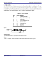
1
Applied Radar, Inc.
www.appliedradar.com
AR2010
USB Stick Synthesizer
Generation II
User Manual
Revision 2.0.1, June 2012
AR2010 USB Stick Synthesizer
Notices
© Applied Radar, Inc. 2012
No part of this manual may be reproduced in any form or by any means
(including electronic storage and retrieval or translation into a foreign
language) without prior permission
and written consent from Applied
Radar, Inc. as governed by United
States and international copyright
laws.
Manual Part Number
AR2010-99-2
Edition
Revision 2.0.1, June 2012
Printed in the USA
Applied Radar, Inc.
315 Commerce Park Road
Unit 2
North Kingstown, RI 02852 USA
User Manual
Warranty
The material contained in this document is provided "as is," and is subject to be changed, without notice, in
future editions. Further, to the maximum extent permitted by applicable law, Applied Radar disclaims all
warranties, either expressed or implied, with regard to this manual and
any information contained herein, including but not limited to the implied
warranties of merchantability and fitness for a particular purpose. Applied Radar shall not be liable for
errors or incidental or consequential
damages in connection with the furnishing, use, or performance of this
document or of any information contained herein. Should Applied Radar
and the user have a separate written agreement with warranty terms
covering the material in this document that conflict with these terms,
the warranty terms in the separate
agreement shall control.
Safety Notices
CAUTION
A CAUTION notice denotes a hazard. It calls attention to an operating procedure, practice, or the like
that, if not correctly performed or adhered to, could result in damage to
the product or loss of data. Do not
proceed beyond a CAUTION notice
until the indicated conditions are fully
understood and met.
WARNING
A WARNING notice denotes a hazard. It calls attention to an operating procedure, practice, or the
likes that, if not correctly performed or adhered to, could result
in personal injury or death. Do not
proceed beyond a WARNING notice until the indicated conditions
are fully understood and met.
Technology Licenses
The hardware and/or software deTrademark Acknowledgements
scribed in this document are furFedora is a registered trademark of
nished under a license and may be
Red Hat, Inc.
used or copied only in accordance
with the terms of such license.
LINUX is a registered trademark of
Linus Torvalds.
Restricted Rights Legend
U.S. Government Restricted Rights.
Mac and Mac OS is a registered Software and technical data rights
trademark of Apple Inc.
granted to the federal government
include only those rights customMATLAB is a registered trademark arily provided to end user cusof The MathWorks, Inc.
tomers. Applied Radar, Inc. provides this customary commercial liNI-VISA is a registered trademark of cense in Software and technical data
the National Instruments Corporation pursuant to FAR 12.211 (Technical
Data) and 12.212 (Computer SoftNI-VXI is a registered trademark of ware) and, for the Department of Dethe National Instruments Corporta- fense, DFARS 252.227-7015 (Techtion
nical Data - Commercial Items) and
DFARS 227.7202-3 (Rights in ComWindows is a U.S. registered trade- mercial Computer Software or Commark of Microsoft Corporation.
puter Software Documentation).
Applied Radar, Inc.
Revision 2.0.1
i
AR2010 USB Stick Synthesizer
User Manual
Restricted Rights Legend
The Software and Documentation have been developed entirely at private expense. They are delivered
and licensed as "commercial computer software" as defined in DFARS 252.227-7013 (Oct 1988), DFARS
252.211-7015 (May 1991), or DFARS 252.227-7014 (Jun 1995), as a "commercial item" as defined in FAR
2.101(a) or as "restricted computer software" as defined in FAR 25.227-19 (Jun 1987) (or any equivalent
agency regulation or contract clause), whichever is applicable.The End User has only those rights provided for such Software and Documentation by the applicable FAR or DFARS clause or the Applied Radar
standard software agreement for the product involved.
General Warranty
The material contained in this document is provided "as is," and is subjected to being changed, without
notice, in future editions. Further, to the maximum extent permitted by applicable law, Applied Radar,
Inc. disclaims all warranties, either expressed or implied with regard to this manual and any information
contained herein, including but not limited to the implied warranties of merchantability and fitness for a
particular purpose. Applied Radar, Inc. shall not be liable for errors or for incidental or consequential
damages in connection with the furnishing, use, or performance of this document or any information
contained herein. Should Applied Radar and the user have a separate written agreement with warranty
terms covering the material in this document that conflict with these terms, the warranty terms in the
separate agreement shall control. Duration and conditions of warranty for this product may be superseded
when the product is integrated into (becomes part of) other Applied Radar products. During the warranty
period, Applied Radar will, at its option, either repair or replace products which prove to be defective. The
warranty period begins on the date of delivery or on the date of installation if installed by Applied Radar.
Product Safety
The following general safety precautions must be observed during all phases of operation of this device.
Failure to comply with these precautions or with specific warnings elsewhere in this manual violates
safety standards of design, manufacture, and intended use of this device. Applied Radar, Inc. assumes
no liability for the customer’s failure to comply with these requirements.
Safety Notices
CAUTION
A CAUTION notice denotes a hazard. It calls attention to an operating procedure, practice, or the like
that, if not correctly performed or adhered to, could result in damage to the product or loss of data. Do
not proceed beyond a CAUTION notice until the indicated conditions are fully understood and met.
WARNING
A WARNING notice denotes a hazard. It calls attention to an operating procedure, practice, or the
likes that, if not correctly performed or adhered to, could result in personal injury or death. Do not
proceed beyond a WARNING notice until the indicated conditions are fully understood and met.
Personal Safety Considerations
This is a Safety Class I product (provided with a protective earthing ground incorporated in the power
cord). The mains plug shall only be inserted in a socket outlet provided with a protective earth contact.
Applied Radar, Inc.
Revision 2.0.1
ii
AR2010 USB Stick Synthesizer
User Manual
Any interruption of the protective conductor, inside or outside the product, is likely to make the product
dangerous. Intentional interruption is prohibited. If this product is not used as specified, the protection
provided by the equipment could be impaired. This product must be used in a normal condition (in which
all means of protection are intact) only.
No operator serviceable parts inside. Refer servicing to qualified personnel. To prevent electrical shock,
do not remove covers. For continued protection against fire hazard, replace the line fuse(s) only with
fuses of the same type and rating (for example, normal blow, time delay, etc.). The use of other fuses or
material is prohibited.
General Safety Information
The following general safety precautions must be observed during all phases of operation of this product. Failure to comply with these precautions or with specific warnings elsewhere in this manual or any
manual associated with this product violates safety standards of design, manufacture, and intended use
of the product. Applied Radar, Inc. assumes no liability for the customer’s failure to comply with these
requirements.
WARNING
BEFORE APPLYING POWER TO THIS PRODUCT OR MAKING ANY CONNECTIONS TO THIS PRODUCT ensure that all instruments are connected to the protective (earth) ground. Any interruption
of the protective earth grounding will cause a potential shock hazard that could result in personal
injury or death.
CAUTION
∙ Use this device with the cables provided.
∙ Do not attempt to service this device. This device should be returned to Applied Radar,
Inc. for any service or repairs.
∙ Do not open the device.
User Environment
This instrument is designed for indoor use only.
Applied Radar, Inc.
Revision 2.0.1
iii
AR2010 USB Stick Synthesizer
User Manual
Markings
The following markings may appear on the equipment or in any related documentation.
J
ESD Sensitive
This marking indicates that a device, or part of a device, may be susceptible
to electrostatic discharges (ESD) which can result in damage to the product.
Observed ESD precautions given on the product, or in its user documentation,
when handling equipment bearing this mark.
This marking indicates that the device complies with applicable sections of part
15 of the FCC rules.
Part 15
This marking indicates that the device complies with the Virtual Instrument Software Architecture (VISA) specification.
This marking indicates that the device complies with the Standard Commands
for Programmable Instrumentation (SCPI) specification.
This marking indicates that the device complies with the USB Test & Measurement Class (USBTMC) and the USB 488 subclass specifications.
This marking indicates that the device complies with the VME eXtensions for
Instrumentation (VXI) specification.
This marking indicates that the device complies with the LAN eXtensions for
Instrumentation (LXI) specification.
Î
Applied Radar, Inc.
This marking indicates that the device communicates over the RS232 Serial Bus.
Revision 2.0.1
iv
AR2010 USB Stick Synthesizer
User Manual
This marking indicates that the device communicates over the Universal Serial
Bus (USB).
This marking indicates that the device communicates over Ethernet.
This marking indicates that the device is USB Low Speed and Full Speed certified.
This marking indicates that the device is USB On The Go (OTG) Low Speed and
Full Speed certified.
This marking indicates that the device is USB High Speed certified.
This marking indicates that the device is USB On The Go (OTG) High Speed
certified.
This marking indicates that the device communicates over the proprietary Applied Radar Expansion Bus. This expansion bus allows multiple Applied Radar
products to be connected to a common host board to provide a single connection
to the control computer.
Applied Radar, Inc.
Revision 2.0.1
v
AR2010 USB Stick Synthesizer
User Manual
Revision Control
Revision
1.0.0
Description of Changes
Date
Initial Creation
08/18/2011
Applied Radar, Inc.
Revision 2.0.1
vi
AR2010 USB Stick Synthesizer
Applied Radar, Inc.
User Manual
Revision 2.0.1
vii
AR2010 USB Stick Synthesizer
User Manual
Contents
Notices . . . . . . . . . . . . . . . . . .
Manual Part Number . . . . .
Edition . . . . . . . . . . . . .
Trademark Acknowledgements
Warranty . . . . . . . . . . . .
Technology Licenses . . . . .
Restricted Rights Legend . . .
Safety Notices . . . . . . . . .
Restricted Rights Legend . . .
General Warranty . . . . . . .
Product Safety . . . . . . . . . . . . . .
Safety Notices . . . . . . . . . . . .
Personal Safety Considerations . . .
General Safety Information . . . . .
User Environment . . . . . . . . . .
Markings . . . . . . . . . . . . . . .
Revision Control . . . . . . . . . . . . .
.
.
.
.
.
.
.
.
.
.
.
.
.
.
.
.
.
i
i
i
i
i
i
i
i
ii
ii
ii
ii
ii
iii
iii
iv
vi
1 Product Overview
1. AR2010 USB Stick Synthesizer Overview . . . . . . . . . . . . . . . . . . . . . . . . . . . . .
2. Part Number . . . . . . . . . . . . . . . . . . . . . . . . . . . . . . . . . . . . . . . . . . . . .
2
3
3
2 Remote Operation
1. Introduction . . . . . . . . . . . . . . . . . . . .
1.1 USB Configuration . . . . . . . . . . . .
1.2 Command Syntax . . . . . . . . . . . . .
1.2.1 Mnemonic Forms . . . . . . . . .
1.2.2 Using a Semicolon(;) . . . . . . .
1.2.3 Using Whitespace . . . . . . . . .
1.2.4 Using "?" Commands . . . . . . .
1.2.5 Using "*" Commands . . . . . . .
1.3 Diagram Syntax Conventions . . . . . . .
1.4 Default Units . . . . . . . . . . . . . . . .
1.5 Status Reporting . . . . . . . . . . . . .
1.6 SCPI Data Types . . . . . . . . . . . . .
1.6.1 <boolean> Definition . . . . . . .
1.6.2 <character_data> Definition . . .
1.6.3 <NAN> Definition . . . . . . . . .
1.6.4 <non-decimal numeric> Definition
1.6.5 <NRf> Definition . . . . . . . . .
4
6
6
6
6
6
6
6
6
6
7
7
7
7
8
8
8
8
Applied Radar, Inc.
.
.
.
.
.
.
.
.
.
.
.
.
.
.
.
.
.
.
.
.
.
.
.
.
.
.
.
.
.
.
.
.
.
.
.
.
.
.
.
.
.
.
.
.
.
.
.
.
.
.
.
.
.
.
.
.
.
.
.
.
.
.
.
.
.
.
.
.
.
.
.
.
.
.
.
.
.
.
.
.
.
.
.
.
.
.
.
.
.
.
.
.
.
.
.
.
.
.
.
.
.
.
.
.
.
.
.
.
.
.
.
.
.
.
.
.
.
.
.
.
.
.
.
.
.
.
.
.
.
.
.
.
.
.
.
.
.
.
.
.
.
.
.
.
.
.
.
.
.
.
.
.
.
.
.
.
.
.
.
.
.
.
.
.
.
.
.
.
.
.
.
.
.
.
.
.
.
.
.
.
.
.
.
.
.
.
.
.
.
.
.
.
.
.
.
.
.
.
.
.
.
.
.
.
.
.
.
.
.
.
.
.
.
.
.
.
.
.
.
.
.
.
.
.
.
.
.
.
.
.
.
.
.
.
.
.
.
.
Revision 2.0.1
.
.
.
.
.
.
.
.
.
.
.
.
.
.
.
.
.
.
.
.
.
.
.
.
.
.
.
.
.
.
.
.
.
.
.
.
.
.
.
.
.
.
.
.
.
.
.
.
.
.
.
.
.
.
.
.
.
.
.
.
.
.
.
.
.
.
.
.
.
.
.
.
.
.
.
.
.
.
.
.
.
.
.
.
.
.
.
.
.
.
.
.
.
.
.
.
.
.
.
.
.
.
.
.
.
.
.
.
.
.
.
.
.
.
.
.
.
.
.
.
.
.
.
.
.
.
.
.
.
.
.
.
.
.
.
.
.
.
.
.
.
.
.
.
.
.
.
.
.
.
.
.
.
.
.
.
.
.
.
.
.
.
.
.
.
.
.
.
.
.
.
.
.
.
.
.
.
.
.
.
.
.
.
.
.
.
.
.
.
.
.
.
.
.
.
.
.
.
.
.
.
.
.
.
.
.
.
.
.
.
.
.
.
.
.
.
.
.
.
.
.
.
.
.
.
.
.
.
.
.
.
.
.
.
.
.
.
.
.
.
.
.
.
.
.
.
.
.
.
.
.
.
.
.
.
.
.
.
.
.
.
.
.
.
.
.
.
.
.
.
.
.
.
.
.
.
.
.
.
.
.
.
.
.
.
.
.
.
.
.
.
.
.
.
.
.
.
.
.
.
.
.
.
.
.
.
.
.
.
.
.
.
.
.
.
.
.
.
.
.
.
.
.
.
.
.
.
.
.
.
.
.
.
.
.
.
.
.
.
.
.
.
.
.
.
.
.
.
.
.
.
.
.
.
.
.
.
.
.
.
.
.
.
.
.
.
.
.
.
.
.
.
.
.
.
.
.
.
.
.
.
.
.
.
.
.
.
.
.
.
.
.
.
.
.
.
.
.
.
.
.
.
.
.
.
.
.
.
.
.
.
.
.
.
.
.
.
.
.
.
.
.
.
.
.
.
.
.
.
.
.
.
.
.
.
.
.
.
.
.
.
.
.
.
.
.
.
.
.
.
.
.
.
.
.
.
.
.
.
.
.
.
.
.
.
.
.
.
.
.
.
.
.
.
.
.
.
.
.
.
.
.
.
.
.
.
.
.
.
.
.
.
.
.
.
.
.
.
.
.
.
.
.
.
.
.
.
.
.
.
.
.
.
.
.
.
.
.
.
.
.
.
.
.
.
.
.
.
.
.
.
.
.
.
.
.
.
.
.
.
.
.
.
.
.
.
.
.
.
.
.
.
.
.
.
.
.
.
.
.
.
.
.
.
.
.
.
.
.
.
.
.
.
.
.
.
.
.
.
.
.
.
.
.
.
.
.
.
.
.
.
.
.
.
.
.
.
.
.
.
.
.
.
.
.
.
.
.
.
.
.
.
.
.
.
.
.
.
.
.
.
.
.
.
.
.
.
.
.
.
.
.
.
.
.
.
.
.
.
.
.
.
.
.
.
.
.
.
.
.
.
.
.
.
.
.
.
.
.
.
.
.
.
.
.
.
.
.
.
.
.
.
.
.
.
.
.
.
.
.
.
.
.
.
.
.
.
.
.
.
.
.
.
.
.
.
.
.
.
.
.
.
.
.
.
.
.
.
.
.
.
.
.
.
.
.
.
.
.
.
.
.
.
.
.
.
.
.
.
.
.
viii
AR2010 USB Stick Synthesizer
1.7
1.8
User Manual
1.6.6 <NR1> Definition . . . . . .
1.6.7 <NR2> Definition . . . . . .
1.6.8 <NR3> Definition . . . . . .
1.6.9 <numeric_value> Definition
1.6.10 <string> Definition . . . . .
Input Message Terminators . . . . .
Compliance Information . . . . . . .
1.8.1 IEEE-488.2 Compliance . .
1.8.2 SCPI Compliance . . . . . .
1.8.3 USBTMC Compliance . . . .
1.8.4 VISA Compliance . . . . . .
3 Command Quick Reference Guide
1. Common (*) Commands . . . . . . .
2. FREQuency Subsystem . . . . . . .
3. POWER Subsystem . . . . . . . . .
4. SYSTem Subsystem . . . . . . . . .
4 FREQuency Subsystem
1. FREQuency:LOCK . . . . . . . . . .
2. FREQuency:PLLMode . . . . . . . .
3. FREQuency:REFerence:DIVider . .
4. FREQuency:REFerence:EXTernal .
5. FREQuency:REFerence:FREQuency
6. FREQuency:RETreiveACTual . . . .
7. FREQuency:SET . . . . . . . . . . .
.
.
.
.
.
.
.
.
.
.
.
.
.
.
.
.
.
.
.
.
.
.
.
.
.
.
.
.
.
.
.
.
.
.
.
.
.
.
.
.
.
.
.
.
.
.
.
.
.
.
.
.
.
.
.
.
.
.
.
.
.
.
.
.
.
.
.
.
.
.
.
.
.
.
.
.
.
.
.
.
.
.
.
.
.
.
.
.
.
.
.
.
.
.
.
.
.
.
.
.
.
.
.
.
.
.
.
.
.
.
.
.
.
.
.
.
.
.
.
.
.
.
.
.
.
.
.
.
.
.
.
.
.
.
.
.
.
.
.
.
.
.
.
.
.
.
.
.
.
.
.
.
.
.
.
.
.
.
.
.
.
.
.
.
.
.
.
.
.
.
.
.
.
.
.
.
.
.
.
.
.
.
.
.
.
.
.
.
.
.
.
.
.
.
.
.
.
.
.
.
.
.
.
.
.
.
.
.
.
.
.
.
.
.
.
.
.
.
.
.
.
.
.
.
.
.
.
.
.
.
.
.
.
.
.
.
.
.
.
.
.
.
.
.
.
.
.
.
.
.
.
.
.
.
.
.
.
.
.
.
.
.
.
.
.
.
.
.
.
.
.
.
.
.
.
.
.
.
.
.
.
.
.
.
.
.
.
.
.
.
.
.
.
.
.
.
.
.
.
.
.
.
.
.
.
.
.
.
.
.
.
.
.
.
.
.
.
.
.
.
.
.
.
.
.
.
.
.
.
.
.
.
.
.
.
.
.
.
.
.
.
.
.
.
.
.
.
.
.
.
.
.
8
8
9
9
9
10
10
10
10
11
11
.
.
.
.
.
.
.
.
.
.
.
.
.
.
.
.
.
.
.
.
.
.
.
.
.
.
.
.
.
.
.
.
.
.
.
.
.
.
.
.
.
.
.
.
.
.
.
.
.
.
.
.
.
.
.
.
.
.
.
.
.
.
.
.
.
.
.
.
.
.
.
.
.
.
.
.
.
.
.
.
.
.
.
.
.
.
.
.
.
.
.
.
.
.
.
.
.
.
.
.
.
.
.
.
.
.
.
.
.
.
.
.
.
.
.
.
12
13
14
14
14
.
.
.
.
.
.
.
16
17
18
20
21
22
23
24
.
.
.
.
.
.
.
.
.
.
.
.
.
.
.
.
.
.
.
.
.
.
.
.
.
.
.
.
.
.
.
.
.
.
.
.
.
.
.
.
.
.
.
.
.
.
.
.
.
.
.
.
.
.
.
.
.
.
.
.
.
.
.
.
.
.
.
.
.
.
.
.
.
.
.
.
.
.
.
.
.
.
.
.
.
.
.
.
.
.
.
.
.
.
.
.
.
.
.
.
.
.
.
.
.
.
.
.
.
.
.
.
.
.
.
.
.
.
.
.
.
.
.
.
.
.
.
.
.
.
.
.
.
.
.
.
.
.
.
.
.
.
.
.
.
.
.
.
.
.
.
.
.
.
.
.
.
.
.
.
.
.
.
.
.
.
.
.
.
.
.
.
.
.
.
.
.
.
.
.
.
.
.
.
.
.
.
.
.
.
.
.
.
.
.
.
5 POWEr Subsystem
25
1. POWEr:RF . . . . . . . . . . . . . . . . . . . . . . . . . . . . . . . . . . . . . . . . . . . . . . 26
2. POWEr:SET . . . . . . . . . . . . . . . . . . . . . . . . . . . . . . . . . . . . . . . . . . . . . 27
6 SYSTem Subsystem
1. SYSTem:ERRor . . . . . . . . . .
2. SYSTem:FIRMware . . . . . . . .
3. SYSTem:OPTions . . . . . . . . .
4. SYSTem:SERialNUMber . . . . . .
5. SYSTem:STATus . . . . . . . . . .
6. SYSTem:TEMPerature . . . . . . .
7. SYSTem:TEMPeratureTHRESHold
8. SYSTem:OVERTEMPerature . . .
9. SYSTem:VERSion . . . . . . . . .
10. SYSTem:SAVESTATE . . . . . . .
11. SYSTem:LOADSTATE . . . . . . .
12. SYSTem:BOOTSTATE . . . . . . .
13. SYSTem:READSTATE . . . . . . .
.
.
.
.
.
.
.
.
.
.
.
.
.
.
.
.
.
.
.
.
.
.
.
.
.
.
.
.
.
.
.
.
.
.
.
.
.
.
.
.
.
.
.
.
.
.
.
.
.
.
.
.
.
.
.
.
.
.
.
.
.
.
.
.
.
.
.
.
.
.
.
.
.
.
.
.
.
.
.
.
.
.
.
.
.
.
.
.
.
.
.
.
.
.
.
.
.
.
.
.
.
.
.
.
.
.
.
.
.
.
.
.
.
.
.
.
.
.
.
.
.
.
.
.
.
.
.
.
.
.
.
.
.
.
.
.
.
.
.
.
.
.
.
7 IEEE 488.2 Command Reference
Applied Radar, Inc.
.
.
.
.
.
.
.
.
.
.
.
.
.
.
.
.
.
.
.
.
.
.
.
.
.
.
.
.
.
.
.
.
.
.
.
.
.
.
.
.
.
.
.
.
.
.
.
.
.
.
.
.
.
.
.
.
.
.
.
.
.
.
.
.
.
.
.
.
.
.
.
.
.
.
.
.
.
.
.
.
.
.
.
.
.
.
.
.
.
.
.
.
.
.
.
.
.
.
.
.
.
.
.
.
.
.
.
.
.
.
.
.
.
.
.
.
.
.
.
.
.
.
.
.
.
.
.
.
.
.
.
.
.
.
.
.
.
.
.
.
.
.
.
.
.
.
.
.
.
.
.
.
.
.
.
.
.
.
.
.
.
.
.
.
.
.
.
.
.
.
.
.
.
.
.
.
.
.
.
.
.
.
.
.
.
.
.
.
.
.
.
.
.
.
.
.
.
.
.
.
.
.
.
.
.
.
.
.
.
.
.
.
.
.
.
.
.
.
.
.
.
.
.
.
.
.
.
.
.
.
.
.
.
.
.
.
.
.
.
.
.
.
.
.
.
.
.
.
.
.
.
.
.
.
.
.
.
.
.
.
.
.
.
.
.
.
.
.
.
.
.
.
.
.
.
.
.
.
.
.
.
.
.
.
.
.
28
29
33
34
35
36
37
38
39
40
41
42
43
44
45
Revision 2.0.1
ix
AR2010 USB Stick Synthesizer
1.
2.
3.
4.
5.
6.
7.
8.
9.
10.
11.
12.
13.
14.
15.
16.
User Manual
SCPI Compliance Information . . . . . .
*CLS . . . . . . . . . . . . . . . . . . .
*ESE <NRf> . . . . . . . . . . . . . . .
*ESR? . . . . . . . . . . . . . . . . . .
*IDN? . . . . . . . . . . . . . . . . . . .
*OPC . . . . . . . . . . . . . . . . . . .
*OPT? . . . . . . . . . . . . . . . . . .
*RCL <NRf> . . . . . . . . . . . . . . .
*RST . . . . . . . . . . . . . . . . . . .
*SAV <NRf> . . . . . . . . . . . . . . .
*SRE <NRf> . . . . . . . . . . . . . . .
*STB? . . . . . . . . . . . . . . . . . . .
*TRG . . . . . . . . . . . . . . . . . . .
*TST? . . . . . . . . . . . . . . . . . . .
*WAI . . . . . . . . . . . . . . . . . . .
USBTMC/USB488 Universal Commands
.
.
.
.
.
.
.
.
.
.
.
.
.
.
.
.
.
.
.
.
.
.
.
.
.
.
.
.
.
.
.
.
.
.
.
.
.
.
.
.
.
.
.
.
.
.
.
.
.
.
.
.
.
.
.
.
.
.
.
.
.
.
.
.
.
.
.
.
.
.
.
.
.
.
.
.
.
.
.
.
.
.
.
.
.
.
.
.
.
.
.
.
.
.
.
.
.
.
.
.
.
.
.
.
.
.
.
.
.
.
.
.
.
.
.
.
.
.
.
.
.
.
.
.
.
.
.
.
Index
Applied Radar, Inc.
.
.
.
.
.
.
.
.
.
.
.
.
.
.
.
.
.
.
.
.
.
.
.
.
.
.
.
.
.
.
.
.
.
.
.
.
.
.
.
.
.
.
.
.
.
.
.
.
.
.
.
.
.
.
.
.
.
.
.
.
.
.
.
.
.
.
.
.
.
.
.
.
.
.
.
.
.
.
.
.
.
.
.
.
.
.
.
.
.
.
.
.
.
.
.
.
.
.
.
.
.
.
.
.
.
.
.
.
.
.
.
.
.
.
.
.
.
.
.
.
.
.
.
.
.
.
.
.
.
.
.
.
.
.
.
.
.
.
.
.
.
.
.
.
.
.
.
.
.
.
.
.
.
.
.
.
.
.
.
.
.
.
.
.
.
.
.
.
.
.
.
.
.
.
.
.
.
.
.
.
.
.
.
.
.
.
.
.
.
.
.
.
.
.
.
.
.
.
.
.
.
.
.
.
.
.
.
.
.
.
.
.
.
.
.
.
.
.
.
.
.
.
.
.
.
.
.
.
.
.
.
.
.
.
.
.
.
.
.
.
.
.
.
.
.
.
.
.
.
.
.
.
.
.
.
.
.
.
.
.
.
.
.
.
.
.
.
.
.
.
.
.
.
.
.
.
.
.
.
.
.
.
.
.
.
.
.
.
.
.
.
.
.
.
.
.
.
.
.
.
.
.
.
.
.
.
.
.
.
.
.
.
.
.
.
.
.
.
.
.
.
.
.
.
.
.
.
.
.
.
.
.
.
.
.
.
.
.
.
.
.
.
.
.
.
.
.
.
.
.
.
.
46
47
48
49
50
51
52
53
54
55
56
57
59
60
61
62
62
Revision 2.0.1
x
AR2010 USB Stick Synthesizer
User Manual
List of Tables
2.2 Default Units . . . . . . . . . . . . . . . . . . . . . . . . . . . . . . . . . . . . . . . . . . .
3.1
3.2
3.3
3.4
Common (*) Commands Summary . . . . . . .
FREQuency subsystem Commands Summary
POWER subsystem Commands Summary . .
SYSTem subsystem Commands Summary . .
.
.
.
.
.
.
.
.
.
.
.
.
.
.
.
.
.
.
.
.
.
.
.
.
.
.
.
.
.
.
.
.
.
.
.
.
.
.
.
.
.
.
.
.
.
.
.
.
.
.
.
.
.
.
.
.
.
.
.
.
.
.
.
.
.
.
.
.
.
.
.
.
.
.
.
.
.
.
.
.
.
.
.
.
.
.
.
.
.
.
.
.
.
.
.
.
7
13
14
14
14
4.1 Comparison between Integer and Fractional PLL modes . . . . . . . . . . . . . . . . . . . 18
6.1 Error Codes and Messages . . . . . . . . . . . . . . . . . . . . . . . . . . . . . . . . . . . 29
6.2 Status Codes and Messages . . . . . . . . . . . . . . . . . . . . . . . . . . . . . . . . . . 36
7.1
7.2
7.3
7.4
7.5
7.6
IEEE 488.2 Common commands .
*ESE bit mapping . . . . . . . . .
*ESR? mapping . . . . . . . . . .
*OPC mapping . . . . . . . . . .
*SRE bit mapping . . . . . . . . .
*STB? mapping . . . . . . . . . .
Applied Radar, Inc.
.
.
.
.
.
.
.
.
.
.
.
.
.
.
.
.
.
.
.
.
.
.
.
.
.
.
.
.
.
.
.
.
.
.
.
.
.
.
.
.
.
.
.
.
.
.
.
.
.
.
.
.
.
.
Revision 2.0.1
.
.
.
.
.
.
.
.
.
.
.
.
.
.
.
.
.
.
.
.
.
.
.
.
.
.
.
.
.
.
.
.
.
.
.
.
.
.
.
.
.
.
.
.
.
.
.
.
.
.
.
.
.
.
.
.
.
.
.
.
.
.
.
.
.
.
.
.
.
.
.
.
.
.
.
.
.
.
.
.
.
.
.
.
.
.
.
.
.
.
.
.
.
.
.
.
.
.
.
.
.
.
.
.
.
.
.
.
.
.
.
.
.
.
.
.
.
.
.
.
.
.
.
.
.
.
.
.
.
.
.
.
46
48
49
51
56
57
1
AR2010 USB Stick Synthesizer
User Manual
1
Product Overview
In This Chapter
1.
AR2010 USB Stick Synthesizer Overview . . . . . . . . . . . . . . . . . . . . . . . . . . . . .
3
2.
Part Number . . . . . . . . . . . . . . . . . . . . . . . . . . . . . . . . . . . . . . . . . . . . .
3
Applied Radar, Inc.
Revision 2.0.1
2
AR2010 USB Stick Synthesizer
User Manual
1. AR2010 USB Stick Synthesizer Overview
The AR2010 USB Stick Synthesizer product line is a low-cost, wideband PLL based line of frequency
synthesizers ideally suited for bench top test and measurement as well as low-cost small form-factor
radar and communications systems. The AR2010 is USB bus powered so it must be connected to a USB
port on the computer or through powered USB hub for operation. The output power of the AR2010 is user
adjustable in power steps dependent on the model number. The AR2010 features an internal reference
for independent operation. The AR2010 may be operated off an an externally applied reference signal
between 10 MHz and 70 MHz through the MMCX connector on the side of the AR2010, allowing the
AR2010 to be synchronized with other test equipment.
The AR2010 includes three indicator LEDs on the side of the case, a blue LED which when lit indicates
that the AR2010 has been enumerated by the computer, the reference selector LED which indicates use
of an external reference when lit and an internal reference when off, and the Lock LED. The Lock LED
indicates the lock status of the AR2010. When green, the AR2010 is locked and when red the AR2010 is
unlocked.
The AR2010 USB Stick Synthesizer is available in a black or white housing.
2. Part Number
The part number for the USB Stick Synthesizer is in the format AR2010-XX-YY, where XX is the lower
operating frequency limit in MHz or GHz and YY is the upper operating frequency limit in MHz or GHz.
For example, AR2010-138-4400 identifies the USB Stick Synthesizer as having an operating range of
138 MHz to 4400 MHz and a part number of AR2010-5-10 identifies the USB Stick Synthesizer as having
an operating range of 5 GHz to 10 GHz.
Applied Radar, Inc.
Revision 2.0.1
3
AR2010 USB Stick Synthesizer
User Manual
2
Remote Operation
In This Chapter
1.
Introduction . . . . . . . . . . . . . . . . . . . . . . . . . . . . . . . . . . . . . . . . . . . . . .
6
1.1
USB Configuration . . . . . . . . . . . . . . . . . . . . . . . . . . . . . . . . . . . . . . . . . . .
6
1.2
Command Syntax
. . . . . . . . . . . . . . . . . . . . . . . . . . . . . . . . . . . . . . . . . . .
6
1.2.1
Mnemonic Forms . . . . . . . . . . . . . . . . . . . . . . . . . . . . . . . . . . . . . . . .
6
1.2.2
Using a Semicolon(;) . . . . . . . . . . . . . . . . . . . . . . . . . . . . . . . . . . . . . .
6
1.2.3
Using Whitespace . . . . . . . . . . . . . . . . . . . . . . . . . . . . . . . . . . . . . . .
6
1.2.4
Using "?" Commands . . . . . . . . . . . . . . . . . . . . . . . . . . . . . . . . . . . . .
6
1.2.5
Using "*" Commands . . . . . . . . . . . . . . . . . . . . . . . . . . . . . . . . . . . . . .
6
1.3
Diagram Syntax Conventions . . . . . . . . . . . . . . . . . . . . . . . . . . . . . . . . . . . . .
6
1.4
Default Units . . . . . . . . . . . . . . . . . . . . . . . . . . . . . . . . . . . . . . . . . . . . . .
7
1.5
Status Reporting . . . . . . . . . . . . . . . . . . . . . . . . . . . . . . . . . . . . . . . . . . . .
7
1.6
SCPI Data Types . . . . . . . . . . . . . . . . . . . . . . . . . . . . . . . . . . . . . . . . . . . .
7
1.6.1
<boolean> Definition . . . . . . . . . . . . . . . . . . . . . . . . . . . . . . . . . . . . .
7
1.6.2
<character_data> Definition . . . . . . . . . . . . . . . . . . . . . . . . . . . . . . . . .
8
1.6.3
<NAN> Definition . . . . . . . . . . . . . . . . . . . . . . . . . . . . . . . . . . . . . . .
8
1.6.4
<non-decimal numeric> Definition . . . . . . . . . . . . . . . . . . . . . . . . . . . . . .
8
1.6.5
<NRf> Definition . . . . . . . . . . . . . . . . . . . . . . . . . . . . . . . . . . . . . . .
8
1.6.6
<NR1> Definition . . . . . . . . . . . . . . . . . . . . . . . . . . . . . . . . . . . . . . .
8
1.6.7
<NR2> Definition . . . . . . . . . . . . . . . . . . . . . . . . . . . . . . . . . . . . . . .
8
1.6.8
<NR3> Definition . . . . . . . . . . . . . . . . . . . . . . . . . . . . . . . . . . . . . . .
9
1.6.9
<numeric_value> Definition . . . . . . . . . . . . . . . . . . . . . . . . . . . . . . . . . .
9
1.6.10 <string> Definition . . . . . . . . . . . . . . . . . . . . . . . . . . . . . . . . . . . . . . .
9
1.7
Input Message Terminators . . . . . . . . . . . . . . . . . . . . . . . . . . . . . . . . . . . . . .
10
1.8
Compliance Information . . . . . . . . . . . . . . . . . . . . . . . . . . . . . . . . . . . . . . . .
10
1.8.1
IEEE-488.2 Compliance . . . . . . . . . . . . . . . . . . . . . . . . . . . . . . . . . . . .
10
1.8.2
SCPI Compliance . . . . . . . . . . . . . . . . . . . . . . . . . . . . . . . . . . . . . . .
10
Applied Radar, Inc.
Revision 2.0.1
4
AR2010 USB Stick Synthesizer
User Manual
1.8.3
USBTMC Compliance . . . . . . . . . . . . . . . . . . . . . . . . . . . . . . . . . . . . .
11
1.8.4
VISA Compliance
11
. . . . . . . . . . . . . . . . . . . . . . . . . . . . . . . . . . . . . . .
The following markings apply to the AR2010 USB Stick Synthesizer family of products.
J
ESD Sensitive
Applied Radar, Inc.
Revision 2.0.1
5
AR2010 USB Stick Synthesizer
User Manual
1. Introduction
1.1 USB Configuration
The Applied Radar AR2010 USB Stick Synthesizer has been designed to configure as a USB Test and
Measurement Class (USBTMC) device. No additional drivers are required.
The AR2010 has been designed to be Virtual Instrument Software Architecture (VISA) and Standard
Commands for Programmable Instrumentation (SCPI) compliant and as such, all you need in order to
communicate with the USB Stick Synthesizer is a VISA library installed on your machine. The AR2010
will work with any of the three major providers of VISA; National Instruments, Agilent, and Tektronics. If
you do not have a VISA library installed, please visit one of the three vendors listed above to obtain a
legal copy of the VISA library.
1.2 Command Syntax
In this manual, the following command syntax conventions are used:
∙ Square brackets ([ ]) indicate multiple keywords, one of which must be used
∙ Bars(|) can be read as "or" and are used to separate parameter options.
1.2.1 Mnemonic Forms
Each keyword has both a long and short form. A standard notation is used to differentiate the short form
and long form keyword. The long form of the keyword is shown, with the short form of the keyword shown
in uppercase letters and the rest of the keyword is shown in lowercase letters. For example, the short
form of FREQuency is FREQ.
1.2.2 Using a Semicolon(;)
Use a semicolon to separate two commands within the same command string.
1.2.3 Using Whitespace
You must use whitespace characters, [tab], or [space] to separate a parameter from a keyword.
1.2.4 Using "?" Commands
The bus controller may send commands at any time, but a SCPI instrument may only send a response
when specifically instructed to do so. Only commands that end with a "?", henceforth referred to as
queries, instruct the instrument to send a response message. Queries can return either measured values, instrument settings, or internal status codes.
Note: If you send multiple queries without reading the response between queries, only the result of the
last query will be returned when the response is read. The query buffer is a first-in first-out configuration.
1.2.5 Using "*" Commands
Commands starting with a "*" are called common commands. They are required to perform identical
functions for all instruments that are compliant with the IEEE-488.2 interface standard. The "*" commands
are used to control reset, self-test, and status operations in the USB Stick Synthesizer.
1.3 Diagram Syntax Conventions
∙ Solid lines represent the recommended path
Applied Radar, Inc.
Revision 2.0.1
6
AR2010 USB Stick Synthesizer
User Manual
∙ Ovals enclose command mnemonics. The command mnemonic must be entered exactly as shown
in the oval.
∙ Dotted lines indicate an optional path for passing secondary or optional keywords.
∙ Arrows and curved intersections indicate command path direction.
∙ All diagrams flow from left to right. A path may not travel to the left except in a bypass loop.
1.4 Default Units
Unless otherwise specified, the following units are assumed:
Table 2.2: Default Units
Current
mA
Frequency
GHz
Power
dBm
Time
ms
Temperature
°C
Voltage
Volts
1.5 Status Reporting
Status reporting is used to monitor the USB Stick Synthesizer to determine which events have occurred.
Status reporting in accomplished by configuring and reading status registers.
The USB Stick Synthesizer has the following main registers:
∙
∙
∙
∙
∙
Status Register
Standard Event Register
Operation Status Register
Questionable Status Register
Device Status Register
Status and Standard Event registers are read using the IEEE-488.2 common commands.
Operation and Questionable Status registers are read using the SCPI STAT subsystem.
1.6 SCPI Data Types
The SCPI language defines different formats for use in program messages and response messages.
Instruments are flexible listeners and can accept commands and parameters in various formats. However,
SCPI instruments are precise talkers. This means that SCPI instruments always responds to a particular
query in a predefined, rigid format.
1.6.1 <boolean> Definition
Throughout this document <boolean> is used to represent ON|OFF| <NRf>. Boolean parameters have
a value of 0 or 1 and are unitless. ON corresponds to 1 and OFF corresponds to 0.
On input, an <NRf> is rounded to an integer. A nonzero result is interpreted as 1.
Queries always return a 1 or a 0, never ON or OFF.
Applied Radar, Inc.
Revision 2.0.1
7
AR2010 USB Stick Synthesizer
User Manual
1.6.2 <character_data> Definition
Throughout this document, <character_data> is used to represent character data, that is, A-Z, a-z, 09 and _ (underscore). STOP and A4_U2 are examples of character data. The first character must
be alphanumeric, followed by either alphanumeric or underscore characters up to a maximum of 12
characters.
1.6.3 <NAN> Definition
Not a number (NAN) is represented as 9.91 E37. Not a number is defined in IEEE 754.
1.6.4 <non-decimal numeric> Definition
Throughout this document, <non-decimal numeric> is used to represent numeric information in bases
other than 10 (that is, hexadecimal, octal, and binary). Examples of non-decimal numeric include #HFF4,
#hff4, #Q25, #q25, and #B101011.
1.6.5 <NRf> Definition
Throughout this document, <NRf> is used to denote a flexible numeric representation. The following
show examples of <NRf>
∙ +185
∙ -10
∙ +1.2E09
1.6.6 <NR1> Definition
Throughout this document, <NR1> numeric response data is defined as:
+
Digit
-
The following shows the examples of <NR1>:
∙ 127
∙ +127
∙ -12345
1.6.7 <NR2> Definition
Throughout this document, <NR2> numeric response data is defined as:
+
Digit
.
Digit
-
The following shows the examples of <NR2>:
Applied Radar, Inc.
Revision 2.0.1
8
AR2010 USB Stick Synthesizer
∙
∙
∙
∙
User Manual
12.7
+127
-1.2345
-0.123
1.6.8 <NR3> Definition
Throughout this document, <NR3> numeric response data is defined as:
+
∙
Digit
Digit
-
+
E
Digit
-
The following shows the examples of <NR3>:
∙ 1.23E+4
∙ 12.3E-45
1.6.9 <numeric_value> Definition
Throughout this document, the decimal numeric element is abbreviated to <numeric_value>.
1.6.10 <string> Definition
Throughout this document, <string> is used to represent the 7-bit ASCII characters. The format is defined as:
Applied Radar, Inc.
Revision 2.0.1
9
AR2010 USB Stick Synthesizer
User Manual
Program Data
’
<inserted ’>
’
’
<non ’ char>
"
<inserted ">
"
"
<non " char>
Response Data
"
<inserted ">
"
"
<non " char>
1.7 Input Message Terminators
Program messages sent to a SCPI instrument must terminate with a <newline> character. The IEEE.488
EOI (end or identify) signal is interpreted as a <newline> character and may also be used to terminate a
message in place of the <newline> character. A <carriage return> followed by a <newline> character
is also accepted. Many programming languages allow you to specify a message terminator character
or EOI state to be automatically sent with each bus transaction. Message termination always sets the
current path back to the root-level.
1.8 Compliance Information
1.8.1 IEEE-488.2 Compliance
The USB Stick Synthesizer complies with the rules and regulations of the of the IEEE-488.2 standard
which are applicable to USB controlled devices.
1.8.2 SCPI Compliance
The USB Stick Synthesizer complies with the rules and regulations of the of the SCPI (Standard Commands for Programmable Instruments). You can determine the SCPI version which the USB Stick Synthesizer complies with by sending the SYSTem:VERSion? command from the remote interface.
Applied Radar, Inc.
Revision 2.0.1
10
AR2010 USB Stick Synthesizer
User Manual
1.8.3 USBTMC Compliance
The AR2010 USB Stick Synthesizer complies with the rules and regulations of the of the USBTMC (USB
Test and Measurement Class). When connected to a USB bus, the AR2010 will configure as a USB Test
and Measurement device.
1.8.4 VISA Compliance
The AR2010 USB Stick Synthesizer complies with the rules and regulations of the of the VISA (Virtual
Instrument Systems Architecture) standard. Communication with the AR2010 is accomplished through
VISA libraries, providing portability between different operating systems. No additional drivers are required.
Applied Radar, Inc.
Revision 2.0.1
11
AR2010 USB Stick Synthesizer
User Manual
3
Command Quick
Reference Guide
In This Chapter
1.
Common (*) Commands . . . . . . . . . . . . . . . . . . . . . . . . . . . . . . . . . . . . . . . 13
2.
FREQuency Subsystem . . . . . . . . . . . . . . . . . . . . . . . . . . . . . . . . . . . . . . . 14
3.
POWER Subsystem . . . . . . . . . . . . . . . . . . . . . . . . . . . . . . . . . . . . . . . . . 14
4.
SYSTem Subsystem . . . . . . . . . . . . . . . . . . . . . . . . . . . . . . . . . . . . . . . . . 14
Applied Radar, Inc.
Revision 2.0.1
12
AR2010 USB Stick Synthesizer
User Manual
1. Common (*) Commands
Table 3.1: Common (*) Commands Summary
Command
Page
Description
*CLS
47
Clears the data structures. The SCPI registers are
cleared.
*ESE <NRf>
48
Sets the Standard Event Status Enable Register.
*ESE?
48
Returns the Standard Event Status Enable Register.
*ESR?
49
Returns the contents of the Standard Event Status
Register and then clears it.
*IDN?
50
Returns the identification of the device connected to
the computer (Host).
*OPC
51
Causes the USB Stick Synthesizer to set the operation complete bit in the Standard Event Status Register
when all pending operations have completed.
*OPC?
51
Returns the operation complete bit in the Standard
Event Status Register when all pending operations
have completed.
*OPT?
52
Returns the USB Stick Synthesizer installed options.
*RCL <NRf>
53
Recalls the state of the USB Stick Synthesizer from
the specified register (memory location).
*RST
54
Returns the USB Stick Synthesizer to its initial power
up state.
*SAV <NRf>
55
Saves the state of the USB Stick Synthesizer to the
specified register (memory location).
*SRE <NRf>
56
Sets the Service Request Enable register bits.
*SRE?
56
Returns the Service Request Enable register bits.
*STB?
57
Returns the USB Stick Synthesizer status byte.
*TRG
59
Triggers the USB Stick Synthesizer.
*TST?
60
Performs a self test of the USB Stick Synthesizer.
*WAI
61
Causes the USB Stick Synthesizer to wait until either
all pending commands are complete, the Device Clear
command is received, or the power is cycled before
executing any subsequent commands or queries.
DCL
62
Causes all USB instruments to assume a cleared condition.
Applied Radar, Inc.
Revision 2.0.1
13
AR2010 USB Stick Synthesizer
User Manual
2. FREQuency Subsystem
Table 3.2: FREQuency subsystem Commands Summary
Command
Page
Description
FREQuency:LOCK
17
Returns the lock status of the device.
FREQuency:PLLMode
18
Sets or Returns the PLL Mode of the device to Integer
or Fractional.
FREQuency:REFerence:DIVider
20
Sets or Returns the reference divider value for the PLL
of the device.
FREQuency:REFerence:EXTernal
21
Sets or Returns whether the internal or external supplied reference oscillator is used.
FREQuency:REFerence:FREQuency
22
Sets or Returns the reference frequency in MHz.
When using the internal reference, this should always
be 20 MHz.
FREQuency:RETreiveACTual
23
Returns the actual frequency of the device in GHz.
This query is useful when internal frequency rounding
occurs in integer mode.
FREQuency:SET
24
Sets or Returns the desired tuning frequency in GHz.
3. POWER Subsystem
NOTICE
The POWEr:RF command is only available on the AR2010-4400 and AR2010-5-10 v3.0.1 and higher RF
Synthesizer modules.
Table 3.3: POWER subsystem Commands Summary
Command
Page
Description
POWEr:RF
26
Turns on or off the RF output of the device.
POWEr:SET
27
Sets or Returns the output power of the device.
4. SYSTem Subsystem
Table 3.4: SYSTem subsystem Commands Summary
Command
Page
Description
SYSTem:ERRor
29
Returns the contents of the error queue of the device.
SYSTem:SERialNUMber
35
Returns the serial number of the device.
Applied Radar, Inc.
Revision 2.0.1
14
AR2010 USB Stick Synthesizer
User Manual
SYSTem:STATus
36
Returns the status of the device.
SYSTem:TEMPerature
37
Returns the maximum temperature reading from the
device.
SYSTem:TEMPeratureTHRESHold
38
Sets or returns the user defined over-temperature
threshold value in Celsius.
SYSTem:OVERTEMPerature
39
Returns the over-temperature flag value from the device.
SYSTem:VERSion
40
Returns the version of SCPI used by the device.
SYSTem:SAVESTATE
41
Saves the current parameters to a specified state number.
SYSTem:LOADSTATE
42
Loads and sets the parameters from the specified
state.
SYSTem:BOOTSTATE
43
Specifies a state to boot to at device startup.
SYSTem:READSTATE
44
Reads the parameters from the specified state without
changing the current device setup.
Applied Radar, Inc.
Revision 2.0.1
15
AR2010 USB Stick Synthesizer
User Manual
4
FREQuency Subsystem
In This Chapter
1.
FREQuency:LOCK . . . . . . . . . . . . . . . . . . . . . . . . . . . . . . . . . . . . . . . . . . 17
2.
FREQuency:PLLMode . . . . . . . . . . . . . . . . . . . . . . . . . . . . . . . . . . . . . . . . 18
3.
FREQuency:REFerence:DIVider . . . . . . . . . . . . . . . . . . . . . . . . . . . . . . . . . . 20
4.
FREQuency:REFerence:EXTernal . . . . . . . . . . . . . . . . . . . . . . . . . . . . . . . . . 21
5.
FREQuency:REFerence:FREQuency . . . . . . . . . . . . . . . . . . . . . . . . . . . . . . . . 22
6.
FREQuency:RETreiveACTual . . . . . . . . . . . . . . . . . . . . . . . . . . . . . . . . . . . . 23
7.
FREQuency:SET . . . . . . . . . . . . . . . . . . . . . . . . . . . . . . . . . . . . . . . . . . . 24
Applied Radar, Inc.
Revision 2.0.1
16
AR2010 USB Stick Synthesizer
User Manual
1. FREQuency:LOCK?
This command returns the lock status of the USB Stick Synthesizer. A lock status of 0 indicates that the
device is unlocked, while a lock status of 1 indicates that the device is locked.
Syntax
FREQ
:LOCK
?
Query Example
FREQ:LOCK?
This query returns the lock status of the device
Applied Radar, Inc.
Revision 2.0.1
17
AR2010 USB Stick Synthesizer
User Manual
2. FREQuency:PLLMode [INT|FRAC|1|0]
This command sets the Phase Lock Loop (PLL) mode of the USB Stick Synthesizer. A PLL mode of INT
or 1 indicates that the PLL is operating in Integer mode, while a PLL mode of FRAC or 0 indicates that
the PLL is operating in Fractional Mode.
When the PLL is placed in Integer mode (also referred to as Integer-N mode), the output frequency is an
integer multiple of the reference oscillator frequency divided by the reference divider. For example, if the
reference frequency is 20 MHz, and the reference divider is 2, then when placed in Integer mode, the
synthesizer would be capable of outputting a frequency of 9.0 GHz and 9.010 GHz, but not a frequency
of 9.005 GHz (10 MHz tuning resolution). If there reference is 10 MHz and the reference divider is 1, the
same would situation would apply.
When the PLL is placed in Fractional mode, the output frequency can be any non-integer multiple of the
reference oscillator frequency. In the above example, the synthesizer would be capable of outputting a
frequency of 9.005 GHz when operated in Fractional mode.
Table 4.1 summarizes the advantages and disadvantages of the two synthesizer operational modes.
Table 4.1: Comparison between Integer and Fractional PLL modes
Mode
Advantages
Disadvantages
Integer
Lower Phase Noise
Frequency must be an integer
multiple of the reference frequency
Phase Synchronization between
modules is guaranteed
Fractional
Any frequency can be outputted
Increased Phase Noise
Phase synchronization is difficult
to achieve at best
Syntax
FREQ
:PLLM
Space
INT|FRAC|1|0
?
Example
FREQ:PLLM 1
This command sets the PLL mode of the device to Integer mode.
Applied Radar, Inc.
Revision 2.0.1
18
AR2010 USB Stick Synthesizer
User Manual
Default Condition
On power up, or when a *RST command is issued, the PLL mode setting defaults to the mode stored in
the selected SYSTem:BOOTSTATE.
Query Example
FREQ:PLLM?
This query returns the PLL mode of the device.
∙ 0 is returned if the synthesizer is Fractional Mode
∙ 1 is returned if the synthesizer is in Integer Mode
Applied Radar, Inc.
Revision 2.0.1
19
AR2010 USB Stick Synthesizer
User Manual
3. FREQuency:REFerence:DIVider <numeric value>
This command allows the user to set the frequency reference divider of the USB Stick Synthesizer. The
reference frequency divider is used to provide finer resolution steps in integer mode. The acceptable
range for the reference divider is 1 through 127. The fundamental frequency step size in integer mode is
𝑓𝑟𝑒𝑓
, where 𝑁 is the value of the reference divider.
𝑁
Note: Phase noise will degrade as the REFDIV value increases.
Syntax
FREQ
:REF
:DIV
Space
numeric value (1-127)
?
Allowed Values
The reference frequency divider value can be set to any integer value between 1 and 127.
Example
FREQ:REF:DIV 10
This command sets the reference divider value to 10.
Default Condition
On power up, or when a *RST command is issued, the reference divider value defaults to the frequency
stored in the selected SYSTem:BOOTSTATE.
Query
FREQ:REF:DIV?
Applied Radar, Inc.
This query returns the reference divider value
Revision 2.0.1
20
AR2010 USB Stick Synthesizer
User Manual
4. FREQuency:REFerence:EXTernal [ON|OFF|1|0]
This command allows the user to select between the internal 20 MHz reference and an externally supplied reference. Note that when an external reference is applied, the appropriate reference frequency and
reference divider values must be set. When switching from an external reference to the internal reference,
the reference frequency value will automatically be set to 20 MHz.
When OFF or 0 is specified, the internal reference oscillator is used by the USB Stick Synthesizer.
When ON or 1 is specified, the external reference input is used by the USB Stick Synthesizer.
Syntax
ON|1
FREQ
:REF
:EXT
Space
OFF|0
?
Example
FREQ:REF:EXT 0
This command selects the internal reference oscillator.
Default Condition
On power up, or when a *RST command is issued, the USB Stick Synthesizer defaults to the reference
oscillator state stored in the selected SYSTem:BOOTSTATE.
Query
FREQ:REF:EXT?
This query returns a 0 or 1 to indicate the selected USB Stick Synthesizer reference
mode
∙ 0 is returned if the internal reference is selected
∙ 1 is returned if the external reference oscillator is selected
Applied Radar, Inc.
Revision 2.0.1
21
AR2010 USB Stick Synthesizer
User Manual
5. FREQuency:REFerence:FREQuency <numeric value>
This command allows the user to set the synthesizer reference oscillator frequency in MHz. The allowed
values are between 10 MHz and 70 MHz. The default value is 20 MHz.
Syntax
FREQ
:REF
:FREQ
Space
numeric value
?
Allowed Values
The reference frequency can be set to any integer value between 10 and 70.
Example
FREQ:REF:FREQ 10
This command sets the internal reference oscillator to 10 MHz
Default Condition
On power up, or when a *RST command is issued, the synthesizer reference oscillator frequency defaults
to the reference frequency stored in the selected SYSTem:BOOTSTATE.
Query
FREQ:REF:FREQ?
Applied Radar, Inc.
This query returns the synthesizer reference frequency in MHz.
Revision 2.0.1
22
AR2010 USB Stick Synthesizer
User Manual
6. FREQuency:RETreiveACTual?
This command returns the actual tuned frequency in GHz of the USB Stick Synthesizer. When in integer
mode, the USB Stick Synthesizer is capable of only tuning in discrete steps, and therefore the actual
tuned frequency may vary slightly from the desired frequency set using the FREQ:SET command.
Syntax
FREQ
:RETACT
?
Query Example
FREQ:RETACT?
Applied Radar, Inc.
This query returns the actual tuned frequency in GHz.
Revision 2.0.1
23
AR2010 USB Stick Synthesizer
User Manual
7. FREQuency:SET <numeric value>
This command allows the user to set the frequency of the USB Stick Synthesizer. The frequency value is
specified in GHz.
Syntax
FREQ
:SET
Space
numeric value
?
Example
FREQ:SET 5.5
This command sets the tuning frequency of the device to 5.5 GHz
Default Condition
On power up, or when a *RST command is issued, the synthesizer frequency defaults to the frequency
stored in the selected SYSTem:BOOTSTATE.
Query
FREQ:SET?
This query returns the frequency for the device in GHz.
Error Messages
If the frequency entered is out of the operational range of the device, an error message of 201, "Parameter
specified out of Device operating range" is placed in the device’s error queue.
Applied Radar, Inc.
Revision 2.0.1
24
AR2010 USB Stick Synthesizer
User Manual
5
POWEr Subsystem
In This Chapter
1.
POWEr:RF . . . . . . . . . . . . . . . . . . . . . . . . . . . . . . . . . . . . . . . . . . . . . . 26
2.
POWEr:SET . . . . . . . . . . . . . . . . . . . . . . . . . . . . . . . . . . . . . . . . . . . . . 27
Applied Radar, Inc.
Revision 2.0.1
25
AR2010 USB Stick Synthesizer
User Manual
1. POWEr:RF [ON|OFF|1|0]
This command allows the user to turn on and off the RF output of the USB Stick Synthesizer.
NOTICE
The POWEr:RF command is only available on the AR2010-4400 and AR2010-5-10 v3.0.1 and higher RF
Synthesizer modules.
Syntax
POWE
:RF
Space
ON|OFF|1|0
?
Example
POWE:RF 0
This command turns off the RF.
Default Condition
On power up, or when a SYST:PRES or *RST command is issued, the USB Stick Synthesizer RF output
defaults to the RF OFF state, unless otherwise specified in the product’s Operation Manual.
Query
POWE:RF?
This query returns power output state of the device.
∙ 0 is returned if the RF output is OFF
∙ 1 is returned if the RF output is ON
Error Messages
If the device does not have an integrated mute capability, an error message of 110, "Invalid Command
For Specified Device" is placed in the device’s error queue.
Applied Radar, Inc.
Revision 2.0.1
26
AR2010 USB Stick Synthesizer
User Manual
2. POWEr:SET [numeric value|MIN|MAX]
This command allows the user to set the output power of the AR2010 to a specified numeric value, the
minimum output power level, or the maximum output power level. The range of acceptable input power
values is dependent on frequency. If a specified input value cannot be reached, the AR2010 will automatically set the power level to the next closest value. Power settings stay static across frequency changes;
therefore, if the power level is set to 5 dBm at 6 GHz, changing the frequency to 8 GHz will automatically set the power level to 5 dBm. The same is true when the maximum or minimum value is set, but
note that the maximum output power at 5 GHz may be different from the maximum output power at 9 GHz.
Syntax
POWE
:SET
Space
numeric value|MIN|MAX
?
Example
POWE:SET MAX
This command sets the output power of the device to its maximum value
POWE:SET -10
This command sets the output power of the device to -10 dBm
Default Condition
On power up, or when a *RST command is issued, the AR2010 output power defaults to the power level
stored in the selected SYSTem:BOOTSTATE.
Query
POWE:SET?
-5 (The output power of the device is currently -5 dBm. Neither MAX nor MIN has been
specified.)
POWE:SET?
MAX,15 (MAX has been specified, and the maximum output power at the current frequency is 15 dBm. The two values are separated by a comma.)
Error Messages
If the power entered is out of the operational range of the device, an error message of 201, "Parameter
specified out of Device’s operating range" is placed in the device’s error queue.
Applied Radar, Inc.
Revision 2.0.1
27
AR2010 USB Stick Synthesizer
User Manual
6
SYSTem Subsystem
In This Chapter
1.
SYSTem:ERRor . . . . . . . . . . . . . . . . . . . . . . . . . . . . . . . . . . . . . . . . . . . 29
2.
SYSTem:FIRMware . . . . . . . . . . . . . . . . . . . . . . . . . . . . . . . . . . . . . . . . . 33
3.
SYSTem:OPTions . . . . . . . . . . . . . . . . . . . . . . . . . . . . . . . . . . . . . . . . . . 34
4.
SYSTem:SERialNUMber . . . . . . . . . . . . . . . . . . . . . . . . . . . . . . . . . . . . . . . 35
5.
SYSTem:STATus . . . . . . . . . . . . . . . . . . . . . . . . . . . . . . . . . . . . . . . . . . . 36
6.
SYSTem:TEMPerature . . . . . . . . . . . . . . . . . . . . . . . . . . . . . . . . . . . . . . . . 37
7.
SYSTem:TEMPeratureTHRESHold . . . . . . . . . . . . . . . . . . . . . . . . . . . . . . . . . 38
8.
SYSTem:OVERTEMPerature . . . . . . . . . . . . . . . . . . . . . . . . . . . . . . . . . . . . 39
9.
SYSTem:VERSion . . . . . . . . . . . . . . . . . . . . . . . . . . . . . . . . . . . . . . . . . . 40
10. SYSTem:SAVESTATE . . . . . . . . . . . . . . . . . . . . . . . . . . . . . . . . . . . . . . . . 41
11. SYSTem:LOADSTATE . . . . . . . . . . . . . . . . . . . . . . . . . . . . . . . . . . . . . . . . 42
12. SYSTem:BOOTSTATE . . . . . . . . . . . . . . . . . . . . . . . . . . . . . . . . . . . . . . . . 43
13. SYSTem:READSTATE . . . . . . . . . . . . . . . . . . . . . . . . . . . . . . . . . . . . . . . . 44
Applied Radar, Inc.
Revision 2.0.1
28
AR2010 USB Stick Synthesizer
User Manual
1. SYSTem:ERRor?
This query returns error numbers and messages from the AR2010 error queue. When an error is generated by the AR2010, the error number and corresponding error message is stored in the error queue.
Each time the error queue is queried, the first error in the error queue is returned. The errors are read out
in the order of first-in first-out. To clear all errors in the error queue, use the *CLS command.
When the error queue is empty, a query of the error queue will return a 0, "No error" message. The error
queue has a maximum capacity of 10 errors.
Syntax
SYST
:ERR
?
Query Example
SYST:ERR?
Queries the system error.
Error queue messages have the following format:
Error Number
,
"
Error Description
"
For example, 100, "Syntax Error"
Reset Condition
On reset, the error queue is cleared.
Error Message List
Table 6.1: Error Codes and Messages
-101
Invalid character
Invalid character was found in the command string.
-102
Syntax error
Invalid syntax was found in the command string.
-103
Invalid separator
Invalid separator was found in the command string.
-105
GET not allowed
A Group Execute Trigger (GET) is not allowed within a command string.
-108
Parameter not allowed
More parameters were received than expected for the command.
-109
Missing parameter
Fewer parameters were received than expected for the command.
-112
Program mnemonic too long
A command header was received which contained more than the maximum 12
characters allowed.
Applied Radar, Inc.
Revision 2.0.1
29
AR2010 USB Stick Synthesizer
-113
User Manual
Undefined header
A command was received that is not valid for the USB Stick Synthesizer.
-121
Invalid character in number
An invalid character was found in the number specified for a parameter value.
-123
Exponent too large
A numeric parameter was found whose exponent was larger than 32,000.
-124
Too many digits
A numeric parameter was found whose mantissa contained more than 255 digits.
-128
Numeric data not allowed
A numeric value was received within a command which does not accept a numeric value.
-131
Invalid suffix
A unit was incorrectly specified for a numeric parameter.
-134
Suffix too long
A unit used contained more than 12 characters.
-138
Suffix not allowed
A unit was received following a numeric parameter which does not accept a unit.
-141
Invalid character data
An invalid character was received.
-148
Character data not allowed
A discrete parameter was received but a character string or numeric parameter
was expected.
-151
Invalid string data
An invalid string was received.
-158
String data not allowed
A character string was received but not allowed for the command.
-161
Invalid block data
A block data element was expected but was invalid.
-168
Block data not allowed
A legal block data element was encountered but not allowed by the Product.
-178
Expression data not allowed
A legal expression data element was encountered but not allowed by the Product.
-200
Execution error
Indicates that an execution error has occurred.
-211
Trigger ignored
Applied Radar, Inc.
Revision 2.0.1
30
AR2010 USB Stick Synthesizer
User Manual
Indicates that a trigger command was received but ignored because the USB
Stick Synthesizer was not in the wait for trigger state.
-213
Trigger ignored
Indicates that a trigger command was received but ignored because the USB
Stick Synthesizer was not in the wait for trigger state.
-222
Data out of range
A numeric parameter value is outside the valid range for the command.
-224
Illegal parameter value
A discrete parameter was received which was not a valid choice for the command.
-230
Data corrupt or stale
This occurs when a measurement command is attempted and either a reset has
been received of the state of the USB Stick Synthesizer has changed such that
the measurement is no longer valid.
-241
Hardware missing
The USB Stick Synthesizer is unable to execute the command because the
hardware does not support that feature.
-310
System error
This error indicates a failure with the USB Stick Synthesizer.
-330
Self-test failed
The -330,"Self-test failed" error indicates a problem with the USB Stick Synthesizer.
-350
Queue overflow
The error queue is full and another error has occurred which could not be
recorded.
-410
Query INTERRUPTED
A command was received which sends data to the output buffer, but the output
buffer contained data from a previous command. The output buffer is cleared
when power has been of or after a *RST command has been issued.
-420
Query UNTERMINATED
The USB Stick Synthesizer was addressed to talk but a command has not been
received which sends data to the output buffer.
-430
Query DEADLOCKED
A command was received which generates too much data to fit in the output
buffer and the input buffer is also full. Command execution continues but data
is lost.
-440
Query UNTERMINATED after indefinite response
The *IDN? command must be the last query command within a command string.
-900
Query Temperature above user defined threshold
Applied Radar, Inc.
Revision 2.0.1
31
AR2010 USB Stick Synthesizer
User Manual
The temperature on the device is higher than the user defined threshold temperature. The device is powered off for safety, and will remain powered off until a
user manually powers the device back on.
-901
Query Temperature above factory defined threshold
The temperature on the device is higher than the factory defined threshold temperature above which components may be damaged. The device is powered off
for safety, and will remain powered off until a user manually powers the device
back on.
+0
No error
No errors in the error queue. Device is operating normally.
+110
Invalid Command For Specified Device
The issued command is invalid for the specified device.
Applied Radar, Inc.
Revision 2.0.1
32
AR2010 USB Stick Synthesizer
User Manual
2. SYSTem:FIRMware?
This command returns the current firmware version of the AR2010.
Syntax
Syntax
SYST
:FIRM
?
Query Example
SYST:FIRM?
This query returns the current firmware version of the USB Stick Synthesizer.
Applied Radar, Inc.
Revision 2.0.1
33
AR2010 USB Stick Synthesizer
User Manual
3. SYSTem:OPTions?
This command returns the installed options from the device. The options are returned as a comma separated string of option codes. If no options are installed, a 0 is returned.
Syntax
SYST
:OPT
?
Query Example
SYST:OPT?
This query returns the installed options of the device.
Applied Radar, Inc.
Revision 2.0.1
34
AR2010 USB Stick Synthesizer
User Manual
4. SYSTem:SERialNUMber?
This command returns the serial number of the device.
Syntax
SYST
:SERNUM
?
Query Example
SYST:SERNUM?
Applied Radar, Inc.
This query returns the serial number of the device.
Revision 2.0.1
35
AR2010 USB Stick Synthesizer
User Manual
5. SYSTem:STATus?
This command returns the status of the USB Stick Synthesizer.
Syntax
SYST
:STAT
?
Query Example
SYST:STAT?
This query returns the status of theUSB Stick Synthesizer.
Status messages have the following format:
Status Number
,
"
Status Description
"
For example, 0, "Operational"
Status Message List
Table 6.2: Status Codes and Messages
0
Operational
Device is operating normally
1
Device Has Been Reset
The device has been recently reset
2
Awaiting User Input
Unit is awaiting user input.
100
Recoverable Error Has Occurred
An error has occurred from which the device can recover.
101
Non-Recoverable Error Has Occurred
An error has occurred from which the device can not recover.
110
Over Temperature
The operating temperature of the device exceeds safe operating temperatures.
Applied Radar, Inc.
Revision 2.0.1
36
AR2010 USB Stick Synthesizer
User Manual
6. SYSTem:TEMPerature?
This command returns the maximum temperature reading from the AR2010 in Celsius.
NOTICE
The SYST:TEMP command is only available on AR2010-5-10 v3.0.1 and higher RF Synthesizer modules.
Syntax
SYST
:TEMP
?
Query Example
SYST:TEMP?
This query returns the maximum temperature reading from the USB Stick Synthesizer.
Applied Radar, Inc.
Revision 2.0.1
37
AR2010 USB Stick Synthesizer
User Manual
7. SYST:TEMPeratureTHRESHold <integer>
This command allows the user to set a maximum temperature threshold value for the USB Stick Synthesizer in Celsius. If the on board sensor reads a temperature value above this threshold, the device
will power off the RF power supply. The digital power supply will remain enabled, allowing the user to
communicate with the device.
NOTICE
The SYST:TEMPTHRESH command is only available on the AR2010-5-10 v3.0.1 and higher RF Synthesizer modules.
Syntax
SYST
:TEMPTHRESH
Space
numeric value
?
Example
SYST:TEMPTHRESH 70
This command sets the temperature threshold to 70 degrees Celsius.
Query
SYST:TEMPTHRESH?
Applied Radar, Inc.
This query returns the user defined temperature threshold value.
Revision 2.0.1
38
AR2010 USB Stick Synthesizer
User Manual
8. SYSTem:OVERTEMPerature?
This command returns the over-temperature status of the AR2010. During normal operation, the return
value will be 0. If an over-temperature condition is observed, an error message will be pushed into the
error queue (accessible through SYSTem:ERRor) and the return value will be 1 if the temperature exceeded the user defined threshold, or 0 if it exceeded the factory defined saftey threshold.
NOTICE
The SYST:OVERTEMP command is only available on AR2010-5-10 v3.0.1 and higher RF Synthesizer
modules.
Syntax
SYST
:OVERTEMP
?
Query Example
SYST:OVERTEMP?
Applied Radar, Inc.
This query returns the over-temperature flag value from the USB Stick Synthesizer.
Revision 2.0.1
39
AR2010 USB Stick Synthesizer
User Manual
9. SYSTem:VERSion?
This query returns the version of SCPI used in the USB Stick Synthesizer. The respeonse is in the format
XXXX.Y, where XXXX is the year and Y is the version number.
Syntax
SYST
:VERS
?
Query Example
SYST:VERS?
This query returns the version of SCPI used in the USB Stick Synthesizer.
Applied Radar, Inc.
Revision 2.0.1
40
AR2010 USB Stick Synthesizer
User Manual
10. SYSTem:SAVESTATE [1-5]
This command saves the current setup to non-volatile memory. There are 5 re-writeable memory locations, specified by choosing an index between 1 and 5. Any of the 5 states can be restored on startup
when specified with the SYSTem:BOOTSTATE command. The parameters saved are the PLL mode, frequency, reference divider, reference internal/external, reference frequency, max/min power setting, output
power, RF power (on AR2010-4400 models only).. For a detailed description of the parameters saved,
see your product’s Operation Manual.
Syntax
SYST
:SAVESTATE
Space
1-5
There are 5 memory locations, numbered 1 through 5. Memory location 0 contains the factory default
settings and is write-protected.
Example
SYST:SAVESTATE 3
Applied Radar, Inc.
This command saves the current state to memory location 3
Revision 2.0.1
41
AR2010 USB Stick Synthesizer
User Manual
11. SYSTem:LOADSTATE [0-5]
This command restores a previously saved state from non-volatile memory. In addition to factory default
state 0, there are 5 re-writeable memory locations, specified by choosing an index between 1 and 5. The
restored parameters are the PLL mode, frequency, reference divider, reference internal/external, reference frequency, max/min power setting, output power, RF power (on AR2010-4400 models only).. When
the LOADSTATE command is called, these parameters will be applied to the device.
Syntax
SYST
:LOADSTATE
Space
0-5
There are 6 memory locations, numbered 0 through 5. Memory location 0 contains the factory default
settings, while locations 1-5 are user re-writeable using SYSTem:SAVESTATE.
Example
SYST:LOADSTATE 4
Applied Radar, Inc.
This command loads the state 4 parameters from non-volatile memory and applies them to the device.
Revision 2.0.1
42
AR2010 USB Stick Synthesizer
User Manual
12. SYSTem:BOOTSTATE [0-5]
This command specifies a previously saved state to be loaded upon device startup. In addition to factory
default state 0, there are 5 re-writeable memory locations. Any of these 6 boot states can be selected by
choosing an index between 0 and 5. The restored parameters are the PLL mode, frequency, reference
divider, reference internal/external, reference frequency, max/min power setting, output power, RF power
(on AR2010-4400 models only).
Syntax
SYST
:BOOTSTATE
Space
0-5
There are 6 memory locations, numbered 0 through 5. Memory location 0 contains the factory default
settings, while locations 1-5 are user re-writeable using SYSTem:BOOTSTATE.
Example
SYST:BOOTSTATE 1
This command specifies state 1 to be loaded upon device powerup.
Default Condition
The factory default setting for SYST:BOOTSTATE is 0.
Applied Radar, Inc.
Revision 2.0.1
43
AR2010 USB Stick Synthesizer
User Manual
13. SYST:READSTATE?[value]
The READSTATE query allows the user to read the parameters of the specified state without changing
any internal registers. The query output is a list of comma separated values, without spaces, in the following order: PLL mode, frequency, reference divider, reference internal/external, reference frequency,
max/min power setting, output power, RF power (on AR2010-4400 models only). See the respective
command definitions for descriptions of each parameter.
Syntax
SYST
:READSTATE?
state number
Query
SYST:READSTATE?4
This query requests the parameter values of state 4.
Response: 1,8.000,2,0,20,OFF,0,1,1
∙ 1 = FREQuency:PLLMode is set to integer (page 18)
∙ 8.000 = FREQuency:SET is set to 8 GHz (page 24)
∙ 2 = FREQuency:REFerence:DIVider is set to 2 (page 20)
∙ 0 = FREQuency:REFerence:EXTernal is set to internal (page 21)
∙ 20 = FREQuency:REFerence:FREQuency is set to 20 MHz (page 22)
∙ OFF = The string "OFF" denotes that neither "MAX" nor "MIN" has been specified as the output
power via the POWEr:SET command
∙ 0 = POWEr:SET is set to 0 dBm (page 27)
∙ 1 = POWEr:RF is set to 1 or ON. (page 26). This state parameter is only available on the AR20104400 series; other modules will not return this argument.
Error Messages
If the device does not have an integrated mute capability, an error message of 110, "Invalid Command
For Specified Device" is placed in the device’s error queue.
Applied Radar, Inc.
Revision 2.0.1
44
AR2010 USB Stick Synthesizer
User Manual
7
IEEE 488.2 Command
Reference
In This Chapter
1.
SCPI Compliance Information . . . . . . . . . . . . . . . . . . . . . . . . . . . . . . . . . . . . 46
2.
*CLS . . . . . . . . . . . . . . . . . . . . . . . . . . . . . . . . . . . . . . . . . . . . . . . . . 47
3.
*ESE <NRf> . . . . . . . . . . . . . . . . . . . . . . . . . . . . . . . . . . . . . . . . . . . . . 48
4.
*ESR? . . . . . . . . . . . . . . . . . . . . . . . . . . . . . . . . . . . . . . . . . . . . . . . . 49
5.
*IDN? . . . . . . . . . . . . . . . . . . . . . . . . . . . . . . . . . . . . . . . . . . . . . . . . . 50
6.
*OPC . . . . . . . . . . . . . . . . . . . . . . . . . . . . . . . . . . . . . . . . . . . . . . . . . 51
7.
*OPT? . . . . . . . . . . . . . . . . . . . . . . . . . . . . . . . . . . . . . . . . . . . . . . . . 52
8.
*RCL <NRf> . . . . . . . . . . . . . . . . . . . . . . . . . . . . . . . . . . . . . . . . . . . . . 53
9.
*RST . . . . . . . . . . . . . . . . . . . . . . . . . . . . . . . . . . . . . . . . . . . . . . . . . 54
10. *SAV <NRf> . . . . . . . . . . . . . . . . . . . . . . . . . . . . . . . . . . . . . . . . . . . . . 55
11. *SRE <NRf> . . . . . . . . . . . . . . . . . . . . . . . . . . . . . . . . . . . . . . . . . . . . . 56
12. *STB? . . . . . . . . . . . . . . . . . . . . . . . . . . . . . . . . . . . . . . . . . . . . . . . . . 57
13. *TRG . . . . . . . . . . . . . . . . . . . . . . . . . . . . . . . . . . . . . . . . . . . . . . . . . 59
14. *TST? . . . . . . . . . . . . . . . . . . . . . . . . . . . . . . . . . . . . . . . . . . . . . . . . . 60
15. *WAI . . . . . . . . . . . . . . . . . . . . . . . . . . . . . . . . . . . . . . . . . . . . . . . . . 61
16. USBTMC/USB488 Universal Commands . . . . . . . . . . . . . . . . . . . . . . . . . . . . . . 62
Applied Radar, Inc.
Revision 2.0.1
45
USB Stick Synthesizer
IEEE 488.2 Command Reference
1. SCPI Compliance Information
This chapter contains information on the IEEE-488 Common Commands that the USB Stick Synthesizer
supports.
The IEEE-488.2 Common Command descriptions are listed below.
Table 7.1: IEEE 488.2 Common commands
Applied Radar, Inc.
*CLS
Clear Status
Page 47
*ESE and *ESE?
Event Status Enable
Page 48
*ESR?
Event Status Register
Page 49
*IDN?
Identify
Page 50
*OPC and *OPC?
Operation Complete
Page 51
*OPT?
Options
Page 52
*RCL
Recall
Page 53
*RST
Reset
Page 54
*SAV
Save
Page 55
*SRE and *SRE?
Service Request Enable
Page 56
*STB?
Status Byte
Page 57
*TRG
Trigger
Page 59
*TST?
Test
Page 60
*WAI
Wait
Page 61
Revision 2.0.1
46
USB Stick Synthesizer
IEEE 488.2 Command Reference
2. *CLS
The *CLS (CLear Status) command clears the data structures. The SCPI registers are all cleared.
Syntax
*CLS
Applied Radar, Inc.
Revision 2.0.1
47
USB Stick Synthesizer
IEEE 488.2 Command Reference
3. *ESE <NRf>
The *ESE (Event Status Enable) command sets the Standard Event Status Enable Register. This register contains a mask value for the bits to be enabled in the Standard Event Status Register. A 1 in the
enable register enables the corresponding bit in the Status Register, a 0 disables the corresponding bit
in the Status Register. The parameter value when expressed in base 2, represents the bit values of the
Standard Event Status Enable Register. Table 7.2 shows the contents of this register.
Table 7.2: *ESE bit mapping
Bit
Base 2
Meaning
0
1
Operation Complete
1
2
Request Control (not used)
2
4
Query Error
3
8
Device Dependent Error
4
16
Execution Error
5
32
Command Error
6
64
Not Used
7
128
Power On
Syntax
*ESE
Space
NRf
?
Allowed Values
The NRf parameter can be any integer in the range of 0 to 255.
Query
*ESE?
This query returns the contents of the Standard Event Status Enable Register.
Applied Radar, Inc.
Revision 2.0.1
48
USB Stick Synthesizer
IEEE 488.2 Command Reference
4. *ESR?
The *ESR? query returns the contents of the Standard Event Status Register then clears it. The returned
value is in the range of 0 to 255. Table 7.3 shows the contents of this register.
Table 7.3: *ESR? mapping
Bit
Base 2
Meaning
0
1
Operation Complete
1
2
Not Used
2
4
Query Error
3
8
Device Dependent Error
4
16
Execution Error
5
32
Command Error
6
64
Not Used
7
128
Power On
Syntax
*ESR
Applied Radar, Inc.
?
Revision 2.0.1
49
USB Stick Synthesizer
IEEE 488.2 Command Reference
5. *IDN?
The *IDN? query allows the connected device to identify itself. The string returned is:
Applied Radar,<Product Number>,<Serial Number>,<Firmware>,<Device Id>
where:
∙
∙
∙
∙
<Product Number> identifies the product number of the host
<Serial Number> uniquely identifies the host
<Firmware> returns the firmware of the host
<Device Id> returns the device id of the host
Syntax
*IDN
Applied Radar, Inc.
?
Revision 2.0.1
50
USB Stick Synthesizer
IEEE 488.2 Command Reference
6. *OPC
The *OPC (Operation Complete) command causes the AR2010 USB Stick Synthesizer to set the operation complete bit in the Standard Event Status Register when all pending device operations have been
completed.
Table 7.4: *OPC mapping
Bit
Base 2
Meaning
0
1
Operation Complete
1
2
Not Used
2
4
Query Error
3
8
Device Dependent Error
4
16
Execution Error
5
32
Command Error
6
64
Not Used
7
128
Power On
Syntax
*OPC
?
Query
*OPC?
This query places a 1 in the output queue when all device operations have been completed.
Applied Radar, Inc.
Revision 2.0.1
51
USB Stick Synthesizer
IEEE 488.2 Command Reference
7. *OPT?
The *OPT? query reports the options installed in the AR2010 USB Stick Synthesizer and returns " " empty
string if no options have been installed.
Syntax
*OPT
Applied Radar, Inc.
?
Revision 2.0.1
52
USB Stick Synthesizer
IEEE 488.2 Command Reference
8. *RCL <NRf>
The *RCL (ReCaLl) command restores the state of the AR2010 USB Stick Synthesizer from the specified
save or recall register. Valid register addresses are 0 to 9. A configuration must have been stored previously in the specified register.
Syntax
*RCL
Space
NRf
Allowed Values
The NRf parameter can be any integer in the range of 0 to 9.
Error Message
If the register does not contain a saved state, error 115, "Illegal parameter value" occurs.
Applied Radar, Inc.
Revision 2.0.1
53
USB Stick Synthesizer
IEEE 488.2 Command Reference
9. *RST
The *RST (ReSeT) command returns the AR2010 USB Stick Synthesizer to its initial power-up state.
Syntax
*RST
Applied Radar, Inc.
Revision 2.0.1
54
USB Stick Synthesizer
IEEE 488.2 Command Reference
10. *SAV <NRf>
The *SAV (SAVe) command restores the state of the AR2010 USB Stick Synthesizer from the specified
save or recall register. Valid register addresses are 0 to 9. A configuration must have been stored previously in the specified register.
Syntax
*SAV
Space
NRf
Allowed Values
The NRf parameter can be any integer in the range of 0 to 9.
Applied Radar, Inc.
Revision 2.0.1
55
USB Stick Synthesizer
IEEE 488.2 Command Reference
11. *SRE <NRf>
The *SRE command sets the Service Request Enable register bits. This register contains a mask value
for the bits to be enabled in the Status Byte Register. A 1 in the enable register enables the corresponding
bit in the Status Register, a 0 disables the corresponding bit in the Status Register. The parameter value
when expressed in base 2, represents bits 0 to 5 and bit 7 of the Service Request Enable Register. Bit 6
is not used and is always 0. Table 7.5 shows the contents of this register.
Table 7.5: *SRE bit mapping
Bit
Base 2
Meaning
0
1
Not used
1
2
Not Used (not used)
2
4
Device Dependent
3
8
Questionable Status Summary
4
16
Message Available
5
32
Event Status Bit
6
64
Not Used
7
128
Operation Status Summary
Syntax
*SRE
Space
NRf
?
Allowed Values
The NRf parameter can be any integer in the range of 0 to 255.
Query
*SRE?
This query returns the contents of bits 0 to 5 and bit 7 of the Service Request Enable Register.
Bit 6 is always 0.
Applied Radar, Inc.
Revision 2.0.1
56
USB Stick Synthesizer
IEEE 488.2 Command Reference
12. *STB?
The *STB? (STatus Byte) query returns bit 0 to 5 and bit 7 of the AR2010 USB Stick Synthesizer status
byte and returns the Master Summary Status (MSS) as bit 6. The MSS is inclusive OR of the bitwise
combination (excluding bit 6) of the Status Byte and the Service Request Enable registers. The format of
the return is an integer between 0 and 255. Table 7.6 shows the contents of this register.
Table 7.6: *STB? mapping
Bit
Base 2
Meaning
0
1
Not used
1
2
Device Dependent
0 - No device status condition has occurred
1- A device status condition has occurred
2
4
Error/Event Queue
0 = Queue empty
1 = Queue not empty
3
8
Questionable Status Summary
0 - No QUEStionable status conditions have occurred
1 - A QUEStionable status condition has occurred
4
16
Message Available
0 - no output messages are ready
1 - an output message is ready
5
32
Event Status Bit
0 - no event status has occurred
1 - an event status condition has occurred
6
64
Master Summary Status
0 - USB Stick Synthesizer not requesting service
1 - there is at least one reason for requesting service
7
128
Operation Status Summary
0 = No OPERation status conditions have occurred
1 = An OPERation status condition has occurred
Applied Radar, Inc.
Revision 2.0.1
57
USB Stick Synthesizer
IEEE 488.2 Command Reference
Syntax
*STB
?
Applied Radar, Inc.
Revision 2.0.1
58
USB Stick Synthesizer
IEEE 488.2 Command Reference
13. *TRG
The *TRG (TRiGger) command triggers the AR2010 USB Stick Synthesizer when it is in the waiting for
trigger state.
Syntax
*TRG
Error Message
If the USB Stick Synthesizer is not in the wait-for-trigger state, error 210, "Trigger Ignored occurs.
Applied Radar, Inc.
Revision 2.0.1
59
USB Stick Synthesizer
IEEE 488.2 Command Reference
14. *TST?
The *TST? query causes the AR2010 USB Stick Synthesizer to perform a self-test. The result of the
self-test is placed in the output queue.
∙ 0 is returned if the test passes
∙ 1 is returned if the test fails
Syntax
*TST
Applied Radar, Inc.
?
Revision 2.0.1
60
USB Stick Synthesizer
IEEE 488.2 Command Reference
15. *WAI
The *WAI (WAIt)) command causes the AR2010 USB Stick Synthesizer to wait until either:
∙ All pending operations are complete
∙ The Device Clear command is received
∙ Power is cycled
before executing any subsequent commands or queries.
Syntax
*WAI
Applied Radar, Inc.
Revision 2.0.1
61
USB Stick Synthesizer
IEEE 488.2 Command Reference
16. USBTMC/USB488 Universal Commands
DCL
The DCL (Device CLear) command causes all USB instruments to assume a cleared condition. The
definition of Device Clear is unique for each instrument. For the AR2010 USB Stick Synthesizer:
∙ All pending operations are halted
∙ The parser (the software that interprets the programming codes) is reset and is waiting for the first
character of a programming code.
∙ The output buffer is cleared.
∙ The ARI expansion bus is scanned for attached modules. Any modules found on the ARI expansion
bus are identified.
Applied Radar, Inc.
Revision 2.0.1
62
USB Stick Synthesizer
IEEE 488.2 Command Reference
Index
FREQuency Subsystem
FREQuency:LOCK, 17
FREQuency:PLLMode, 18
FREQuency:REFerence:DIVider, 20
FREQuency:REFerence:EXTernal, 21
FREQuency:REFerence:Frequency, 22
FREQuency:RETreiveACTual, 23
FREQuency:SET, 24
IEEE 488.2 Commands
*CLS, 47
*ESE, 48
*ESR?, 49
*IDN?, 50
*OPC, 51
*OPT?, 52
*RCL, 53
*RST, 54
*SAV, 55
*SRE, 56
*STB?, 57
*TRG, 59
*TST?, 60
*WAI, 61
SCPI Compliance Information, 46
POWEr Subsystem
POWEr:RF, 26
POWEr:SET, 27
Programming Commands
FREQuency:LOCK, 17
FREQuency:PLLMode, 18
FREQuency:REFerence:DIVider, 20
FREQuency:REFerence:EXTernal, 21
FREQuency:REFerence:Frequency, 22
FREQuency:RETreiveACTual, 23
FREQuency:SET, 24
POWEr:RF, 26
POWEr:SET, 27
SYST:TEMPTHRESH, 38
SYSTem:BOOTSTATE, 43
SYSTem:ERRor, 29
Applied Radar, Inc.
SYSTem:FIRMware, 33
SYSTem:LOADSTATE, 42
SYSTem:OPTions, 34
SYSTem:OVERTEMPerature, 39
SYSTem:SAVESTATE, 41
SYSTem:SERialNUMber, 35
SYSTem:STATus, 36
SYSTem:TEMPerature, 37
SYSTem:VERSion, 40
SYSTory:READSTATE, 44
SYSTem Subsystem
SYST:TEMPTHRESH, 38
SYSTem:BOOTSTATE, 43
SYSTem:ERRor, 29
SYSTem:FIRMware, 33
SYSTem:LOADSTATE, 42
SYSTem:OPTions, 34
SYSTem:OVERTEMPerature, 39
SYSTem:SAVESTATE, 41
SYSTem:SERialNUMber, 35
SYSTem:STATus, 36
SYSTem:TEMPerature, 37
SYSTem:VERSion, 40
SYSTory Subsystem
SYSTory:READSTATE, 44
USBTMC/USB488 Universal Commands
DCL, 62
Command Quick Reference Guide, 12
Default Units, 7
FREQuency Subsystem, 16
General Safety Information, iii
IEEE 488.2 Command Reference, 45
Introduction, 6
Command Syntax, 6
Mnemonic Forms, 6
Using * Commands, 6
Revision 2.0.1
63
USB Stick Synthesizer
IEEE 488.2 Command Reference
Using ? Commands, 6
Using a Semicolon(;), 6
Using Whitespace, 6
Compliance Information, 10
IEEE-488.2 Compliance, 10
SCPI Compliance, 10
USBTMC Compliance, 11
VISA Compliance, 11
Default Units, 7
Diagram Syntax Conventions, 6
Input Message Terminators, 10
Part Number, 3
SCPI Data Types, 7
Status Reporting, 7
USB, 6
Notices, i
POWEr Subsystem, 25
Product Overview, 2
Product Safety, ii
Remote Operation, 4
SYSTem Subsystem, 28
Applied Radar, Inc.
Revision 2.0.1
64
@AR2010-99-2@
AR2010-99-2
Revision 2.0.1, June 2012
Applied Radar, Inc.
www.appliedradar.com