1
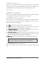
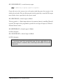
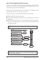
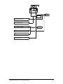
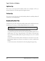
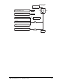
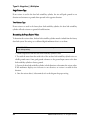
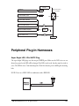
460XV Model
Installation Guide
© 2005 Directed Electronics, Inc. Vista, CA
N460V 04-05
Important! The Viper 460XV system is designed to be installed
in any petrol or common rail diesel vehicle with a 12-volt battery.
The Bitwriter® (p/n 998T)
requires chip version 2.1 or
newer to program this unit.
Bitwriter®, Clifford®, Code-Hopping®, Directed®, Doubleguard®, ESP®, FailSafe®, Ghost Switch™,
Learn Routine™, Nite-Lite®, Nuisance Prevention®, Revenger®, Silent Mode™, Soft Chirp®,
Stealth Coding™, Stinger®, Valet®, Vehicle Recovery SystemTM, VRS®, and Warn Away® are all
Trademarks or Registered Trademarks of Directed Electronics, Inc.
Table of Contents
Primary Harness (H1) Wire Connection Guide ............................................................................5
Primary Harness Wiring Diagram.............................................................................................5
Primary Harness Wiring Instructions........................................................................................5
pigtail harness wire connection guide ............................................................................................9
Auxiliary Harness Wire Connection Guide .................................................................................10
Auxiliary Harness Wiring Diagram .........................................................................................10
Auxiliary Harness Wiring Instructions ....................................................................................10
Door Lock Harness Wire Connection Guide ..............................................................................12
Relay Harness Wiring Diagram...............................................................................................12
Identifying the Door Lock System ..........................................................................................13
Type A: Positive-Triggered, Relay-Driven System ....................................................................14
Type B: Negative-Triggered, Relay-Driven System ..................................................................15
Type C: Reversing Polarity System ..........................................................................................16
Type D: After-Market Actuators .............................................................................................18
Type E: Mercedes-Benz and Audi (1985 and newer)...............................................................18
Type F: One-Wire System.......................................................................................................19
Type G: Positive (+) Multiplex ................................................................................................20
Type H: Negative (-) Multiplex...............................................................................................22
Peripheral Plug-In Harnesses.......................................................................................................23
Super Bright LED, 2-Pin WHITE Plug..................................................................................23
Valet/Program Button, 2-Pin BLUE Plug ...............................................................................24
Programmer Interface, 3-Pin BLACK Plug .............................................................................24
Mounting the Receiver/Antenna .............................................................................................24
Optional Sensors, 4-Pin White Plug x 2 .................................................................................25
Indicator Light Flash Jumper ......................................................................................................25
Ultrasonic Sensor ........................................................................................................................26
Mounting the Control Module and Transducers .....................................................................26
515ESP Self-Powered Smartsiren ................................................................................................27
Siren Installation Instructions .................................................................................................27
Autoimmobilisation Feature ........................................................................................................28
Auto-immobilisation Sequence................................................................................................28
Disarming the System when Immobilised ...............................................................................28
Bypassing Sensor Inputs ..............................................................................................................29
System Features Learn Routine ...................................................................................................29
System Features Menus ...............................................................................................................32
Menu #1 - Basic Features ........................................................................................................32
Menu #2 - Advanced Features.................................................................................................33
Menu #3 - Advanced Features.................................................................................................34
Bitwriter Features ....................................................................................................................34
Feature Descriptions ...................................................................................................................35
©
2005 Directed Electronics, Inc. all rights reserved
3
Menu #1 - Basic Features ........................................................................................................35
Menu #2 - Advanced Features.................................................................................................36
Menu #3 - Advanced Features.................................................................................................38
Transmitter/Receiver Learn Routine ...........................................................................................40
Transmitter Configurations.........................................................................................................42
Standard Configuration...........................................................................................................42
Ultrasonic Sensor Adjustment .....................................................................................................42
Enter Ultrasonic Sensor Adjustment Mode .............................................................................42
Adjusting the Ultrasonic Sensor Setting ..................................................................................43
Exit Ultrasonic Sensor Adjustment Mode ...............................................................................43
Reset Ultrasonic Sensor to Default Setting..............................................................................44
Arm/Disarm Diagnostics.........................................................................................................44
System Status Chirps...............................................................................................................44
Table of Zones ........................................................................................................................45
Long Term Event History ...........................................................................................................46
Optional Vehicle Recovery System (VRS®) ...............................................................................46
Rapid Resume Logic ...................................................................................................................46
Certificate of Installation .............................................................................................................47
Troubleshooting and System Testing ..........................................................................................47
Checking arm/disarm..............................................................................................................47
Testing disarming without a remote ........................................................................................47
Testing Ignition Trigger...........................................................................................................47
Testing the Pin protection switch(es).......................................................................................47
The system will not arm or disarm..........................................................................................48
The Valet switch does not work ..............................................................................................48
The status LED does not work ...............................................................................................48
Closing the door triggers the system, but opening the door does not......................................48
System will not passively arm until it is remotely armed and then disarmed ...........................48
Wiring Quick Reference Guide H1 & H2..................................................................................49
Wiring Quick Reference Guide ...................................................................................................50
4
©
2005 Directed Electronics, Inc. all rights reserved
Primary Harness (H1) Wire Connection Guide
Primary Harness Wiring Diagram
H1/1
___ ORANGE
H1/2
___ BLACK
(-) Chassis Ground Input
H1/3
___ GREEN
(-) Door Trigger Input, Zone 3
H1/4
___ BLUE
(-) Boot Trigger Input, Zone 1
H1/5
___ VIOLET
H1/6
___ GREY
H1/7
___ N/A
H1/8
___ BROWN
H1/9
___ WHITE/BLUE
H1/10
___ BROWN/BLACK
H1/11
___ WHITE 1
Indicator Light Flash Output
H1/12
___ WHITE 2
Indicator Light Flash Output
H1/13
___ BLACK/WHITE 2
Interior Light Illumination Output (30)
H1/14
___ BLACK/WHITE 1
(+) or (-) Interior Light Illumination Input (87)
H1/15
___ RED/WHITE
H1/16
___ VIOLET/BLACK
Lock 87 (Normally Open)
H1/17
___ GREEN/BLACK
Lock 30 (Common)
H1/18
___ WHITE/BLACK
H1/19
___ VIOLET
H1/20
___ BLUE/BLACK
Ground-When-Armed (-) Output
(+) Door Trigger Input, Zone 3
(-) Bonnet Trigger Input, Zone 6
Not Used
(-) Horn Output
Channel 3 (-) Output
Unlock 87A (Normally Closed)
Channel 2 (-) Output
Lock 87A (Normally Closed)
Unlock 87 (Normally Open)
Unlock 30 (Common)
Primary Harness Wiring Instructions
This guide describes in detail the connection of each wire. Also included are possible applications
of each wire. This system was designed with the ultimate in flexibility and security in mind. Many
of the wires have more than one possible function. Please read carefully to ensure a thorough understanding of this unit.
©
2005 Directed Electronics, Inc. all rights reserved
5
H1/1 ORANGE (-) ground-when-armed output
This wire supplies a (-) ground as long as the system is armed and will turn off when the system is
disarmed. This wire does not provide a ground when AutoImmobilised only. This output can be
used to control additional accessories such as window closers, voice modules or pagers.
H1/2 BLACK (-) chassis ground connection (see Pigtail Harness Wire Connection Guide section)
H1/3 GREEN (-) door trigger input
Most vehicles use negative door trigger circuits. Connect the GREEN wire to a wire showing
ground when any door is opened. When connecting to newer model vehicles there is generally a
need to use individual door triggers. This wire will report Zone 3 if triggered.
NOTE: If using a door trigger wire that has a delay, Advanced Menu 2, feature 6, or the 998T
Bitwriter® can be used to turn Bypass Notification off.
INTERIOR LIGHT
GREEN
(-) DOOR SWITCH
(+) 12V
H1/4 BLUE (-) instant trigger input
This input will respond to a negative input with an instant trigger. It is ideal for boot pins and will
report on Zone 1. It can also be used with Directed single-stage sensors. The wire can also be used
to shunt sensors during operation of auxiliary channels or remote start. (See Bypassing Sensor
Inputs section of this guide.)
H1/5 VIOLET (+) door trigger input
Connect this VIOLET wire to a wire that shows (+)12V when any door is opened. This wire will
report Zone 3.
NOTE: If using a door trigger wire that has a delay, Advanced Menu 2, feature 6, or the 998T
Bitwriter® can be used to turn Bypass Notification off.
INTERIOR LIGHT
(+) DOOR SWITCH
VIOLET
(+) 12V
6
©
2005 Directed Electronics, Inc. all rights reserved
H1/6 GREY (-) bonnet input - zone 6
Connect this wire to the bonnet pin switch. If the bonnet is opened when the alarm is armed, this wire
will trigger the system. This wire can be programmed (Menu 2, feature 12 or the Bitwriter) for
normally open (default) or normally closed for connection to normally closed pin switches.
H1/7 — not used
H1/8 BROWN (-) horn output (200mA)
This wire is a low current output to a relay for the horn to sound when the system has been triggered.
It can be programmed to either pulse or latch on when the alarm is triggered.
H1/9 WHITE/BLUE 200 mA (-) channel output 3
This wire provides a (-) 200 mA output whenever the transmitter button(s) controlling Channel 3
is pressed. This output can be programmed to provide the following types of output (see System
Features Learn Routine section of this guide):
➤
➤
➤
➤
➤
A validity output will send a signal as long as the transmission is received.
A latched output will send a signal continuously when the Channel 3 button(s) is pressed and
released. The signal will continue until channel three is pressed again.
A latched/reset with ignition output works similar to the latched output, but will also reset
(output will stop) when the ignition is turned on and then off.
A 30 (60, 90) second timed output will send a signal for 30 seconds when Channel 3 is pressed.
This output can be turned off during the 30-second period by pressing Channel 3 again. The
BitwriterTM can program from 1 to 90 seconds in 1 second increments.
Remote start output (refer to System Features Menu description for additional information).
IMPORTANT! Never use this wire to drive anything but a relay or a low-current input!
This transistorized output can only supply 200 mA, and connecting directly to a
solenoid, motor, or other high-current device will cause the module to fail.
H1/10 BROWN/BLACK Unlock 87A (Normally Closed)
Refer to Door Lock Harness Wire Connection Guide section for instructions on connecting this
wire.
©
2005 Directed Electronics, Inc. all rights reserved
7
H1/11 and H1/12 White indicator light flash outputs
These wires are the output of an on-board dual make relay and should be connected to wires in the
vehicle that control the indicators. If the vehicle’s indicator lights are controlled by a single wire,
connect both WHITE wires to this single wire.
IMPORTANT! The polarity of this wire is determined by the position of the 10A fuse
mounted on the control module printed circuit board. Always confirm the light flash
polarity before changing the fuse position or damage to the vehicle’s lighting system
could occur. If the indicators are switched positive the fuse must connect to the 12 volt
source, if they are switched negative move the fuse jumper to ground.
H1/13 BLACK/WHITE 2 Interior Light Illumination Output (30)
Connect this wire to the interior light circuit trigger wire or the alarm’s door trigger input wire H1/3
or H1/6. When the alarm is disarmed this wire will provide an output to turn on the interior light
for 30 seconds.
H1/14 BLACK/WHITE 1 (+) or (-) Interior Light Illumination Input (87)
This wire determines the output of the BLACK/WHITE H1/13 wire. If the vehicle has a negative
switched interior light circuit, ground this wire; if the vehicle has a positive switched interior light
circuit, attach this wire (using a fuse) to a 12 volt constant source.
H1/15 RED/WHITE (-) channel 2 (200mA)
This wire produces a 200mA output when activated by the remote control and can be used to
operate a variety of accessories. This is often used to operate a boot/hatch release or other relaydriven function. All accessory outputs can be programmed to different types of outputs. Please see
Programming Note #5.
IMPORTANT! Never use this wire to drive anything but a relay or a low-current input!
This transistorized output can only supply 200 mA, and connecting directly to a
solenoid, motor, or other high-current device will cause the module to fail.
H1/16 VIOLET/BLACK Lock 87 (Normally Open)
Refer to Door Lock Harness Wire Connection Guide section for connections.
H1/17 GREEN/BLACK Lock 30 (Common)
Refer to Door Lock Harness Wire Connection Guide section for connections.
H1/18 WHITE/BLACK Lock 87A (Normally Closed)
Refer to Door Lock Harness Wire Connection Guide section for connections.
8
©
2005 Directed Electronics, Inc. all rights reserved
H1/19 VIOLET Unlock 87 (Normally Open)
Refer to Door Lock Harness Wire Connection Guide section for connections.
H1/20 BLUE/BLACK Unlock 30 (Common)
Refer to Door Lock Harness Wire Connection Guide section for connections.
pigtail harness wire connection guide
Locate the ignition and starter wires using a multimeter. Cut the appropriate wires and attach the
key side and car side wires to the corresponding pigtail harness wires.
Ignition Ignition Side
Ignition Key Side
From Control
Module (pigtail wires)
STR Starter Side
Starter Key Side
Starter
x
CUT
Ignition
x
CUT
Locate the fuel pump wire using a multimeter. Cut the appropriate wires and attach the key side
and car side wires to the corresponding pigtail harness wires.
From Control
Module (pigtail wires)
Fuel Pump Out
Fuel Pump
or
Relay
Fuel Pump In
Fuel Pump Wire
Fuse Box
x
CUT
NOTE: The current handling capacity of each immobilisation circuit is 20 amps
continuous and 30 amps peak.
©
2005 Directed Electronics, Inc. all rights reserved
9
Connect the BLACK Ground wire and H1/2 BLACK ground wire to separate ground locations
using a factory bolt that does NOT have any vehicle component grounds attached to it or drill a
new hole if required. A screw should only be used in conjunction with a two-sided lock washer.
Under dash brackets and door sheet metal are not acceptable ground points.
Connect the BLACK +12V power supply wire to an unfused source at the vehicle’s fusebox. Use the
supplied fuse holder and a 15 amp fuse.
NOTE: Remove all tags from pigtail harness wires after installation.
Auxiliary Harness Wire Connection Guide
Auxiliary Harness Wiring Diagram
H2/1
___ LIGHT BLUE
H2/2
___ ORANGE/BLACK
H2/3
___ GREY/BLACK
(-) Channel 6 Output
H2/4
___ WHITE/BLACK
(-) Channel 5 Output
H2/5
___ VIOLET/BLACK
(-) Channel 4 Output
H2/6
___ LIGHT GREEN/BLACK
(-) Second Unlock
Retained Accessory Output
(-) Factory Disarm Output
Auxiliary Harness Wiring Instructions
H2/1 LIGHT BLUE (-) second unlock output (200mA)
This wire produces a (-) 200mA output for vehicles with progressive/selective door unlock, where
the driver’s door unlocks first and the remaining doors unlock with a second press of the unlock
button.
10
©
2005 Directed Electronics, Inc. all rights reserved
H2/2 ORANGE/BLACK (-) retained accessory output
NOTE: An additional relay (not supplied) is required for most applications.
Connect this wire to the accessory wire at the ignition switch that powers the accessories in the
vehicle such as the radio. This wire will retain power after the ignition key is turned off. This output
turns off when a door is open/closed or the system is armed.
H2/3 GREY/BLACK (-) channel output 6 (200mA)
This wire provides a (-) 200mA output whenever the transmitter button(s) controlling Channel 6
is pressed. This output can be programmed to provide the several types of outputs (see Menu #3 Advanced Features section)
H2/4 WHITE/BLACK (-) channel output 5 (200mA)
See H2/3 description.
H2/5 VIOLET/BLACK (-) channel output 4 (200mA)
See H2/3 description.
IMPORTANT! Never use these wires (H2/3, H2/4, H2/5) to drive anything but a relay
or a low-current input! This transistorised output can only supply 200 mA, and
connecting directly to a solenoid, motor, or other high-current device will cause the
module to fail.
©
2005 Directed Electronics, Inc. all rights reserved
11
H2/6 LIGHT GREEN/BLACK (-) factory disarm output
This wire sends a negative pulse every time the alarm is disarmed or the optional remote start is
activated. This can be used to pulse the disarm wire of the vehicle's factory anti-theft device. Use a
relay to send a (-) or (+) pulse to the disarm wire as shown in the diagrams below. This also outputs
when Channel 2 is activated. This function is programmable ON/OFF.
Relay for Negative (-) Disarm Wire
Relay for Positive (+) Disarm Wire
Door Lock Harness Wire Connection Guide
Relay Harness Wiring Diagram
H1/10
___ BROWN/BLACK
Unlock #87a Normally Closed
H1/16
___ VIOLET/BLACK*
Lock #87 Normally Open (Input)
H1/17
___ GREEN/BLACK
Lock #30 Common (Output)
H1/18
___ WHITE/BLACK
Lock #87a Normally Closed
H1/19
___ VIOLET*
H1/20
___ BLUE/BLACK
Unlock #87 Normally Open (Input)
Unlock #30 Common (Output)
*NOTE: VIOLET and VIOLET/BLACK are common at fuse holder.
H1 connector central door locking
The system has door lock relays on-board, and can directly interface with most central locking
systems drawing 20 amps or less.
12
©
2005 Directed Electronics, Inc. all rights reserved
Identifying the Door Lock System
There are eight different types of common door lock circuits found in vehicles (some vehicles use
more unusual systems). The eight most common systems are:
➤
➤
➤
➤
➤
➤
➤
➤
©
Type A: Three-wire (+) pulse controlling factory lock relays.
Type B: Three-wire (-) pulse controlling factory lock relays.
Type C: Direct-wired reversing-polarity switches. The switches are wired directly to the motors.
This type of door lock system has no factory relays.
Type D: Aftermarket door servo driven systems. These include slave systems without an actuator
in the driver’s door but with factory actuators in all the other doors. These can be controlled
with the installation of an aftermarket motor in the driver’s door.
Type E: Electronically-activated vacuum systems. This may require special programming of the
system.
Type F: One-wire system.
Type G: Positive (+) multiplex resistor-based circuit.
Type H: Negative (-) multiplex resistor-based circuit.
2005 Directed Electronics, Inc. all rights reserved
13
Type A: Positive-Triggered, Relay-Driven System
The system can control Type A door locks directly, with no additional parts. The switch will have
three wires on it; one will test (+)12 volt constantly. The others will alternately pulse (+)12 volt
when the switch is pressed to the lock or unlock position.
If you cannot get to the switch, and you find a set of wires that pulse (+)12 volt alternately on lock
and unlock, make sure that it is not a Type C direct-wire system.
Cut the wire that pulses (+)12 volt on lock, and then operate the switch to unlock.
➤
➤
➤
If all doors unlock, the vehicle uses type A system.
If you lose all door lock operation in both directions, you are operating the master switch in a
Type C system.
If you lose all door lock operation of one or more, but not all motors, and other doors still work,
you have cut a wire leading directly to one or more motors. You must instead find the actual
wires leading to the switch.
IMPORTANT! Remember that these wires' functions reverse between Type A and
Type B.
BROWN/BLACK
UNLOCK #87A NORMALLY CLOSED
NOT USED
FACTORY LOCK
SWITCH
LOCK
WHITE/BLACK
LOCK #87A NORMALLY CLOSED
UNLOCK
NOT USED
VIOLET/BLACK
LOCK #87 NORMALLY OPEN (INPUT)
15A
BLUE/BLACK
UNLOCK #30 COMMON (OUTPUT)
VEHICLE FUSED
+12 VOLT CONSTANT
VEHICLE (+)
UNLOCK TRIGGER
CIRCUIT
VIOLET
UNLOCK #87 NORMALLY OPEN (INPUT)
VEHICLE (+)
LOCK TRIGGER
CIRCUIT
GREEN/BLACK
LOCK #30 COMMON (OUTPUT)
TO FACTORY
RELAYS
NOTE: Some BMW and VW vehicles will require the door lock output pulse to be
programmed (Menu 1, Feature 7) to 0.4 secs or the windows will either open or close
slightly when arming and disarming.
14
©
2005 Directed Electronics, Inc. all rights reserved
Type B: Negative-Triggered, Relay-Driven System
This system is common in many Toyotas, Nissans, Hondas and most European Ford vehicles.
The switch will have three wires on it, and one wire will test ground all the time. One wire will pulse
negative (-) when the switch locks the doors, and the other wire will pulse negative (-) when the
switch unlocks the doors. This type of system is difficult to mistake for any other type.
IMPORTANT! Remember that these wires' functions reverse between Type A and
Type B.
FACTORY LOCK
SWITCH
LOCK
BROWN/BLACK
UNLOCK #87A NORMALLY CLOSED
NOT USED
WHITE/BLACK
LOCK #87A NORMALLY CLOSED
NOT USED
UNLOCK
VIOLET/BLACK
LOCK #87 NORMALLY OPEN (INPUT)
15A
BLUE/BLACK
UNLOCK #30 COMMON (OUTPUT)
TO CHASSIS
GROUND
VEHICLE (-)
UNLOCK TRIGGER
CIRCUIT
VIOLET
UNLOCK #87 NORMALLY OPEN (INPUT)
GREEN/BLACK
LOCK #30 COMMON (OUTPUT)
VEHICLE (-)
LOCK TRIGGER
CIRCUIT
TO FACTORY
RELAYS
©
2005 Directed Electronics, Inc. all rights reserved
15
Type C: Reversing Polarity System
Use these instructions if the door lock motor/switch has four or five heavy-gauge wires. This type
of switch has two outputs that rest at (-) ground.
IMPORTANT! To interface with these systems, you must cut two switch leads. The relays
must duplicate the factory door lock switches’ operation. The master switch will have one
or two ground inputs, one (+)12V input, and two switch outputs going directly to the slave
switch and through to the motors. These outputs rest at (-) ground. The lock or unlock
wire is switched to (+)12V, while the other wire is still grounded, thus completing the
circuit and powering the motor. This will disconnect the switch from the motor before
supplying the motor with (+)12V, avoiding sending (+)12V directly to (- ) ground.
It is critical to identify the proper wires and locate the master switch to interface properly. Locate
wires that show voltage when the switch is moved to the lock or unlock position. Cut one of the
suspect wires and check operation of the locks from both switches. If one switch loses all operation
in both directions then you have cut one of the correct wires and the switch that is entirely dead is
the master switch. If both switches still operate in any way and one or more door motors have
stopped responding entirely, you have cut a motor lead. Reconnect it and continue to test for
another wire. Once both wires have been located and the master switch identified, cut both wires
and interface as described in the following paragraphs.
WARNING! If these wires are not connected properly, you will send (+)12V directly to
(-) ground, possibly damaging the alarm or the factory switch.
➤
➤
➤
➤
➤
16
WHITE/BLACK: Once both door lock wires are located and cut, connect the white/black wire
to the master switch side of the lock wire. The master switch side will show (+)12V when
activated and (-) ground at rest.
GREEN/BLACK: Connect the green/black wire to the motor side of the lock wire.
VIOLET/BLACK and H2/4 VIOLET: These wires must be connected to constant (+)12 volts
(via a 15-amp fuse). The best connection point for these wires is directly to the positive (+)
battery post or an unfused source at the vehicle fusebox.
BLUE/BLACK: Connect the blue/black wire to the motor side of the unlock wire.
BROWN/BLACK: Connect the brown/black wire to the master switch side of the unlock wire.
The master switch side will show (+)12V when activated and (-) ground at rest.
©
2005 Directed Electronics, Inc. all rights reserved
(+) 12V
X
X
CUT X
CUT X
MOTOR (+)
UNLOCK WIRE
MOTOR (+)
LOCK WIRE
BROWN/BLACK
UNLOCK #87A NORMALLY CLOSED
WHITE/BLACK
LOCK #87A NORMALLY CLOSED
VIOLET/BLACK
LOCK #87 NORMALLY OPEN (INPUT)
15A
+ 12V FUSED
7.5A /MOTOR
BLUE/BLACK
UNLOCK #30 COMMON (OUTPUT)
VIOLET
UNLOCK #87 NORMALLY OPEN (INPUT)
GREEN/BLACK
LOCK #30 COMMON (OUTPUT)
©
2005 Directed Electronics, Inc. all rights reserved
17
Type D: After-Market Actuators
Vehicles without central door locking or with single-point central locking only require additional
door motors. This requires mounting the door lock actuator inside the door. Some vehicles may
only require one actuator installed in the driver's door if all door locks are operated when the driver's
lock is used.
The fuse used on 12 volt inputs should be 7.5A per motor installed in the vehicle.
BROWN/BLACK
UNLOCK #87A NORMALLY CLOSED
WHITE/BLACK
LOCK #87A NORMALLY CLOSED
VIOLET/BLACK
LOCK #87 NORMALLY OPEN (INPUT)
BLUE/BLACK
UNLOCK #30 COMMON (OUTPUT)
VIOLET
UNLOCK #87 NORMALLY OPEN (INPUT)
GREEN/BLACK
LOCK #30 COMMON (OUTPUT)
Type E: Mercedes-Benz and Audi (1985 and newer)
Type E door locks are controlled by an electrically activated vacuum pump. Test by locking doors
from the passenger key cylinder. If all the doors lock, the vehicle's door lock system can be wired as
type E. The control wire can be found in either kick panel and will show (+)12 volt when doors are
unlocked and (-) ground when doors are locked.
To interface see diagram below. The system must be programmed for 3.5 second door lock pulses
up to 1993 and 1 second pulse 1994 or newer.
18
©
2005 Directed Electronics, Inc. all rights reserved
BROWN/BLACK
UNLOCK #87A NORMALLY CLOSED
WHITE/BLACK
LOCK #87A NORMALLY CLOSED
VIOLET/BLACK
LOCK #87 NORMALLY OPEN (INPUT)
BLUE/BLACK
UNLOCK #30 COMMON (OUTPUT)
VIOLET
UNLOCK #87 NORMALLY OPEN (INPUT)
GREEN/BLACK
LOCK #30 COMMON (OUTPUT)
Type F: One-Wire System
Type F door locks usually require a negative pulse to unlock and cutting the wire to lock the door.
In some vehicles, these functions are reversed. These door locks are found most commonly in
Mitsubishi, Proton and Lotus.
BROWN/BLACK
UNLOCK #87A NORMALLY CLOSED
NOT USED
WHITE/BLACK
LOCK #87A NORMALLY CLOSED
VIOLET/BLACK
LOCK #87 NORMALLY OPEN (INPUT)
NOT USED
BLUE/BLACK
UNLOCK #30 COMMON (OUTPUT)
VIOLET
UNLOCK #87 NORMALLY OPEN (INPUT)
GREEN/BLACK
LOCK #30 COMMON (OUTPUT)
©
2005 Directed Electronics, Inc. all rights reserved
19
Type G: Positive (+) Multiplex
Single-Resistor Type
If one resistor is used in the door lock switch/key cylinder, the wire will pulse (+)12V in one
direction and less than (+)12V when operated in the opposite direction.
Two-Resistor Type
If two resistors are used in the factory door lock switch/key cylinder, the switch/key cylinder will
read less than (+)12V in both directions.
Determining the Proper Resistor Values
To determine the resistor values, the door lock switch/key cylinder must be isolated from the factory
door lock system. For testing, use a calibrated digital multimeter that is set to ohms.
IMPORTANT! To ensure an accurate resistance reading, do not touch the resistor or
leads during testing.
1. Cut the output wire from the door lock switch/key cylinder in half.
2. Test with the meter from the switch side of the cut door lock switch/key cylinder wire to a
reliable constant (+)12V source. Some good constant (+)12V references are the power input
source to the door lock switch/key cylinder, the ignition switch power wire, or the (+) terminal
of the battery.
3. Operate the door lock switch/key cylinder in both directions to determine the resistor values.
If the multimeter displays zero resistance in one direction, no resistor is needed for that
direction.
4. Once the resistor value(s) is determined, refer to the wiring diagram for proper wiring.
20
©
2005 Directed Electronics, Inc. all rights reserved
(+)12V
CONSTANT FUSED
BROWN/BLACK
UNLOCK #87A NORMALLY CLOSED
NOT USED
WHITE/BLACK
LOCK #87A NORMALLY CLOSED
NOT USED
DOOR LOCK SWITCH/
KEY CYLINDER
LOCK
UNLOCK
15A
VIOLET/BLACK
LOCK #87 NORMALLY OPEN (INPUT)
BLUE/BLACK
UNLOCK #30 COMMON (OUTPUT)
VEHICLE FUSED
+12 VOLT CONSTANT
LOCK RESISTOR
(IF REQUIRED)
VIOLET
UNLOCK #87 NORMALLY OPEN (INPUT)
GREEN/BLACK
LOCK #30 COMMON (OUTPUT)
©
2005 Directed Electronics, Inc. all rights reserved
UNLOCK RESISTOR
(IF REQUIRED)
BCM
21
Type H: Negative (-) Multiplex
Single-Resistor Type
If one resistor is used in the door lock switch/key cylinder, the wire will pulse ground in one
direction and resistance to ground when operated in the opposite direction.
Two-Resistor Type
If two resistors are used in the factory door lock switch/key cylinder, the door lock switch/key
cylinder will read resistance to ground in both directions.
Determining the Proper Resistor Values
To determine the resistor values, the door lock switch/key cylinder must be isolated from the factory
door lock system. For testing, use a calibrated digital multimeter that is set to ohms.
IMPORTANT! To ensure an accurate resistance reading, do not touch the resistor or
leads during testing.
1. Cut the output wire from the door lock switch/key cylinder in half.
2. Test with the meter from the switch side of the cut door lock switch/key cylinder wire to a
reliable ground source. Some good ground references are the ground input source to the door
lock switch/key cylinder or battery ground.
3. Operate the door lock switch/key cylinder in both directions to determine the resistor values.
If the multimeter displays zero resistance in one direction, no resistor is needed for that
direction.
4. Once the resistor value(s) is determined, refer to the diagram for proper wiring.
22
©
2005 Directed Electronics, Inc. all rights reserved
CHASSIS
GROUND
BROWN/BLACK
UNLOCK #87A NORMALLY CLOSED
NOT USED
WHITE/BLACK
LOCK #87A NORMALLY CLOSED
NOT USED
DOOR LOCK SWITCH/
KEY CYLINDER
LOCK
UNLOCK
VIOLET/BLACK
LOCK #87 NORMALLY OPEN (INPUT)
BLUE/BLACK
UNLOCK #30 COMMON (OUTPUT)
LOCK RESISTOR
(IF REQUIRED)
VIOLET
UNLOCK #87 NORMALLY OPEN (INPUT)
15A
GREEN/BLACK
LOCK #30 COMMON (OUTPUT)
TO CHASSIS
GROUND
UNLOCK RESISTOR
(IF REQUIRED)
BCM
Peripheral Plug-In Harnesses
Super Bright LED, 2-Pin WHITE Plug
The super bright LED plugs into the two-pin WHITE port. Make sure the LED wires are not
shorted to ground as the LED will be damaged. Two LEDs can be used, but they must be wired in
series. The LED fits into a 7mm mounting hole. Check for clearance prior to drilling the mounting
hole.
NOTE: Never use a BLUE LED in combination with a RED LED.
DIA-41
©
2005 Directed Electronics, Inc. all rights reserved
23
Valet/Program Button, 2-Pin BLUE Plug
The Valet/Program button should be accessible from the driver’s seat. It plugs into the BLUE port
on the side of the unit. Since the system includes a remote Valet feature, this button can be hidden.
Consider how the button will be used before choosing a mounting location. Check for rear clearance
before drilling a 7mm hole and mounting the button.
VALET SWITCH
CONTROL
MODULE
GREY
BLACK
Programmer Interface, 3-Pin BLACK Plug
The BLACK three-pin port is provided for programming of the unit using the 998T Bitwriter®.
For more information please refer to the guide packaged with the programmer.
Mounting the Receiver/Antenna
Receiver/antenna position should be discussed with the vehicle’s owner prior to installation, since
the antenna may be visible to the vehicle’s operator.
The best location for the receiver/antenna is centered high on either the front or rear windscreen.
For optimal range, the antenna should be mounted vertically. It can be mounted horizontally in
relation to the windscreen or under the dashboard away from metal, but range will be reduced.
Metallic window tint can also affect range, so this should be a consideration when determining the
mounting location.
After determining the best mounting location, follow these steps:
1.
2.
3.
4.
24
Clean the mounting area with a quality glass cleaner or alcohol to remove any dirt or residue.
Plug the receiver/antenna cable into the receiver/antenna.
Mount the receiver/antenna using the supplied double-sided tape.
Route the receiver/antenna cable to the control module and plug it into the four-pin antenna
connector.
©
2005 Directed Electronics, Inc. all rights reserved
IMPORTANT! To achieve the best possible range, DO NOT leave the antenna cable
bundled under the dash. Always extend the cable full length during installation,
regardless of the antenna mounting location.
Optional Sensors, 4-Pin White Plug x 2
There are two optional sensor input ports. Optional sensors which can be used are proximity, tilt,
shock, or glass breakage. Alarm trigger inputs shorter than 0.8 seconds will trigger the Warn Away®
response, while inputs longer than 0.8 seconds will trigger full alarm sequence and report Zone 4
or Zone 7 for multiplex input.
Indicator Light Flash Jumper
Indicator Light
Flash Jumper
+
Access Panel
©
2005 Directed Electronics, Inc. all rights reserved
25
This jumper is used to determine the indicator light flash output polarity. In the (+) position, the
on-board relay is enabled and the unit will output (+)12V on the WHITE wires, H11/12. In the (-)
position, the two WHITE wires will supply a (-) output suitable for driving negative switching
indicator circuits.
NOTE: Current handling capacity for H11 and H12 Indicator circuits is 10 amps
continuous each.
IMPORTANT! DO NOT connect the WHITE indicator wires to a negative switching
vehicle circuit before changing the programming jumper to the negative polarity
position or damage to the vehicle may occur.
Ultrasonic Sensor
The built-in remotely adjustable Ultrasonic sensor is used to provide coverage of a vehicle’s interior
cabin area. The sensors detect movement inside the vehicle by sensing air disturbance. They should
trigger the alarm if a thief has gained access to the interior of your vehicle.
Mounting the Control Module and Transducers
1. Choose a location under the dashboard for the control module that is close enough that the
transducers will reach the top of the A-pillar on both driver and passenger sides.
2. One transducer is longer than the other, so mount the transducer with the longest harness
furthest from the control module. Use the screws provided or insert the mounting tabs between
the dashboard and windscreen pillar.
3. Angle the sensors towards the top centre of the rear window. If mounted at the top of the Apillars make sure the transducers position does not affect use of the sunvisor.
4. Route the sensor cables to the alarm control module and plug-in. It will report zone 2 if
triggered.
26
©
2005 Directed Electronics, Inc. all rights reserved
515ESP Self-Powered Smartsiren
The siren transmits a two-way digital signal between itself and the control unit. If a thief disconnects power and/or cuts or tampers with any or all of the siren wires while the system is armed, the
siren will sound for five minutes and then reset. Since this will only occur while the system is armed,
there is no need for a siren override key. Unlike other back-up battery sirens that constantly drain
the car battery, Directed's design draws charging current only when the ignition is on (i.e., engine
running). If the internal battery is discharged, the arm/disarm chirps are muted.
Siren Installation Instructions
1. Firmly secure the siren to the engine bay firewall or wing using the screws supplied. Mount
the siren away from areas of water ingress or excessive heat. Point the siren downward to avoid
moisture collecting.
2. Run the cable from the 515ESP Self-Powered Siren through the firewall into the passenger
compartment, being careful not to tear the pins from the end of the cable.
3. Insert the siren wires into the white 3-pin plug as shown in the diagram below.
4. Insert the 3-pin harness with the RED, ORANGE, and BLACK wires into the siren port on
the control unit. The RED wire of this harness has a 3-amp fuse.
5. Insert the white 3-pin plug into the other plug end of the 3-pin harness.
NOTE: The vehicle must be driven for a total of eight hours after the siren has been
installed in order to sufficiently charge the siren’s back-up battery.
SIREN PLUG
RED
3-AMP
FUSE
INSERT WIRE PIN TERMINATIONS
INTO PLUG—OBSERVE WIRE COLORS
RED
BLACK
BLACK
ORANGE
ORANGE
CONTROL UNIT
SIREN PORT
©
2005 Directed Electronics, Inc. all rights reserved
27
Autoimmobilisation Feature
Immobiliser circuits automatically activate after 30 seconds.
NOTE: H1/1 orange ground when armed will not activate during AutoImmobilisation.
Auto-immobilisation Sequence
1. Turn ignition off or disarm alarm.
2. After 30 seconds the systems Immobilisation circuits activate and engage the starter, ignition,
and fuel pump interrupts.
3. LED flashes at ½ normal speed.
Disarming the System when Immobilised
Use one of the following methods to turn off auto-immobilisation.
●
Press the
button of the transmitter or turn the ignition on and press the
button of the
transmitter.
●
Arm
●
Turn the ignition on and enter the system valet/PIN code.
28
the alarm and then disarm
the alarm.
©
2005 Directed Electronics, Inc. all rights reserved
Bypassing Sensor Inputs
There are times when you need to temporarily bypass all sensor inputs to the unit, such as when
activating the windows or leaving a person or pet inside the vehicle. Anytime an auxiliary channel
output is used, sensor inputs are bypassed until 5-seconds after the output turns off.
To temporarily disable a sensor input, arm
the system. Press the
button again and the
system will respond with 3 indicator flashes. This means all sensor warn-away triggers are bypassed.
Press the button again and the system will respond with 4 indicator light flashes. This means all
sensor warn-away and full triggers are bypassed.
System Features Learn Routine
The System Features Learn Routine allows the unit to be customised to the vehicle and user's
requirements. Due to the number of steps, they have been broken up into three menus. It is possible
to access and change any of the feature settings using the Valet/Program button. However, this
process can be greatly simplified by using the 998T Bitwriter®. Any of the settings can be changed
and then assigned to a particular transmitter, up to four, a feature called Owner Recognition. Each
time that particular transmitter is used to disarm the system, the assigned feature settings will be
recalled. Owner Recognition is only possible when programming the unit via the 998T Bitwriter®.
If the system was previously programmed using the 998T Bitwriter®, the learn routine may be
locked. If the siren generates one long chirp when attempting to program the unit, the learn routine
is locked and must be unlocked using the 998T Bitwriter®.
1. Open a door. (The H1/3 GREEN wire or the H1/5 VIOLET wire must be
connected.)
2. Ignition. Turn the ignition on, then back off.
3. Select a Menu. Press and HOLD the Valet/Program button: (The
Valet/Program button must be plugged into the blue port.) After three seconds
the siren will chirp once and the LED will flash once indicating entry to the
Basic Features Menu #1. If this is the menu you wish to access, release the
button and go on to Step 4. If the button is not released, you will jump to the
©
2005 Directed Electronics, Inc. all rights reserved
29
Advanced Features Menu #2 and the siren will chirp twice and the LED will
flash twice. If the button is still not released, you will jump to Advanced
Features Menu #3 and the siren will chirp three times and the LED will flash
3 times. Once you have selected the desired menu, release the Valet/Program
button and then proceed to Step 4. If the button is still not released, you will
jump back to Basic Features Menu #1 and so on.
4. Select a Feature. Press and release the Valet/Program button the number of
times corresponding to the feature you wish to change. For example, to access
the second feature, press and release the button two times. Then press the
button once more and HOLD it. The siren will chirp and the LED will flash
the number of times equal to the step you have accessed.
5. Program the Feature. While HOLDING the Valet/Program button, you can
toggle the feature on and off using the remote transmitter. In this example,
pressing
will select the chirps ON setting and the siren will chirp 1 time.
Pressing
will change the programming to the chirps OFF setting and the
siren will chirp twice. (See System Features Menus section of this guide.)
NOTE: For features with more than 2 settings pressing
will toggle through
all the two-chirp settings and emit the corresponding number of chirps.
6. Release the Valet/Program Button.
Once a feature is programmed:
➤ Other features can be programmed within the same menu.
➤ Another menu can be selected.
➤ The learn routine can be exited if programming is complete.
To access another feature in the same menu:
1. Press and release the Valet/Program button the number of times necessary to advance from the
feature you just programmed to the next one you want to program. Pressing the button more
times than than the final feature number will wrap around to the beginning again. For example,
after pressing 13 times for the final feature in menu 1 another button press will be feature 1.
2. Then press the Valet/Program button once more and HOLD it.
30
©
2005 Directed Electronics, Inc. all rights reserved
For example, if you just programmed the third feature in the menu and you would like to program
the seventh feature in the menu, you would press and release the Valet/Program button four times
and then press it once more and HOLD it. The siren would chirp seven times to confirm access to
the seventh feature.
To select another menu:
1. Press and HOLD the Valet/Program button.
2. After three seconds, the unit will advance to the next menu and the siren will chirp, indicating
which menu has been accessed.
For instance, if you just programmed some features in Menu #1 (Basic Features) and you wish to
program a feature in Menu #2, you press and HOLD the Valet/Program button. After 3-seconds,
the siren chirps twice and the LED flashes twice indicating access to Menu #2. To advance to Menu
#3, continue to HOLD the Valet/Program button an additional 3-seconds until the siren chirps
and LED flashes three times indicating access to Menu #3.
To exit the learn routine do one of the following:
➤ Close the open door.
➤ Turn the ignition on.
➤ No activity for longer than 15 seconds.
©
2005 Directed Electronics, Inc. all rights reserved
31
System Features Menus
Menu #1 - Basic Features
Items in bold text have been programmed to the default setting at the factory.
Feature
Number
One Chirp
Setting
Two-Chirp
Setting
1-1
Active arming
Passive arming
1-2
Chirps (ON)
Chirps (OFF)
1-3
Ignition controlled door locks (ON)
Ignition controlled door locks (OFF)
1-4
Ignition controlled door unlock (ON)
Ignition controlled door unlock (OFF)
1-5
Passive Locking (ON)
Passive locking (OFF)
1-6
Remote Panic (ON)
Remote Panic (OFF)
1-7*
0.8 second door lock pulses
3.5 second door lock pulses/0.4 sec.
1-8
Forced passive arming (ON)
Forced passive arming (OFF)
1-9
Not used
1-10
Vehicle Recovery System (VRS®) (ON)
(VRS®) (OFF)
1-12
Pin Code 1st digit
Pin Code 2nd digit
1-13
Pin Code 3rd digit
Pin Code 4th digit
For feature number 1-7, the 3.5 second door lock pulse setting the siren will chirp twice, the 0.4
second door lock pulse setting the siren will chirp three times.
32
©
2005 Directed Electronics, Inc. all rights reserved
Menu #2 - Advanced Features
Feature
Number
©
One Chirp
Setting
Two-Chirp
Setting
2-1
Remote Sensor Bypass (Enabled)
Remote Sensor Bypass (Disabled)
2-2
Not used
2-3
Not used
2-4
Not used
2-5
Not used
2-6
Bypass Notification (ON)
Bypass Notification (OFF)
2-7
Enhanced Courtesy light Control (Full)
(door only, ignition only, Off)
2-8
Single unlock pulse
Double unlock pulse
2-9
Single lock pulse
Double lock pulse
2-10
Comfort Closure (On)
Comfort Closure (Off)
2-11
Not used
2-12
Bonnet Trigger (normally closed)
Bonnet Trigger (normally open)
2-13
Dual Sensor Trigger Mode (On)
Dual Sensor Trigger Mode (Off)
2-14
High Security Disarm (On)
High Security Disarm (Off)
2005 Directed Electronics, Inc. all rights reserved
33
Menu #3 - Advanced Features
Note: Some of the features described below are only available with the Bitwriter
Feature
Number
®.
One Chirp
Setting
Two-Chirp
Setting
3-1
Horn (pulsed)
Horn (constant)
3-2
Horn Function (full alarm only)
Siren function—chirp length (20mS,
30mS, 40mS, 50mS)
3-3
Factory Disarm with Channel 2 (On)
Factory Disarm with Channel 2 (Off)
3-4
Ground When Armed in Valet (On)
Ground When Armed in Valet® (Off)
3-5
Channel 3: Validity
latched/latched, reset with ignition/30second/60-second/90-second
timed/remote start report
3-6
Channel 3: Linking (Off)
Arm, Disarm, both
3-7
Channel 4: Validity
latched/latched, reset with ignition/30second/60-second/90-second timed
3-8
Channel 4: Linking (Off)
Arm, Disarm, both
3-9
Channel 5: Validity
latched/latched, reset with ignition/30second/60-second/90-second timed
3-10
Channel 5: Linking (Off)
Arm, Disarm, both
3-11
Channel 6: Validity
latched/latched, reset with ignition/30second/60-second/90-second timed
3-12
Channel 6: Linking (Off)
Arm, Disarm, both
3-13
Not used
3-14
Ignition Controlled 2nd Unlock
(Progressive)
®
Ignition Controlled 2nd Unlock
(Immediate - with first unlock)
Bitwriter Features
34
Feature Description
Settings (factory default in bold)
Channel 3 Timed
1–90 seconds (30 seconds)
Channel 4 Timed
1–90 seconds (30 seconds)
Channel 5 Timed
1–90 seconds (30 seconds)
Channel 6 Timed
1–90 seconds (30 seconds)
Zone 2 Ultrasonic sensor adjust
level 0–20
©
2005 Directed Electronics, Inc. all rights reserved
Feature Descriptions
The features of the system are described below. Features that have additional settings that can be
selected with the 998T Bitwriter® are indicated by the following icon:
Menu #1 - Basic Features
1-1 ACTIVE/PASSIVE ARMING: When active arming is selected, the system will only arm when
the transmitter is used. When set to passive, the system will arm automatically 30 seconds after the
last door is closed and the interior light has turned off. To alert the user of passive arming, the siren
will chirp 20 seconds after the door is closed. This provides the user with an audible indication prior
to the system actually arming. At the 30 second mark, the system will arm but the siren will not
chirp.
1-2 CHIRPS ON/OFF: This feature controls the chirps that confirm the arming and disarming of
the system.
1-3 IGNITION CONTROLLED DOOR LOCK ON/OFF: When turned on, the doors will lock
three seconds after the ignition is turned on, if the doors are closed.
1-4 IGNITION CONTROLLED DOOR UNLOCK ON/OFF: When turned on, the doors will
unlock when the ignition is turned off.
1-5 ACTIVE/PASSIVE LOCKING: If passive arming is selected in menu item 1-1, then the system
can be programmed to either lock the doors when passive arming occurs, or only lock the doors when
the system is armed via the transmitter. Active locking means the system will not lock the doors when
it passively arms. Passive locking means that the system will lock the doors when it passively arms.
NOTE: Remember, when passive arming is selected, the unit will chirp 20 seconds after the last
door is closed. The system does not actually arm or lock the doors until 30 seconds after the door
has been closed.
1-6 REMOTE PANIC: This step controls whether or not the Panic Mode is available.
1-7 DOOR LOCK PULSE DURATION: Some vehicles, such as Mercedes-Benz and Audi, require
longer lock and unlock pulses to operate the vacuum pump. Programming the system to provide
3.5 second pulses, will accommodate the door lock interface in these vehicles. The default setting is
0.8 second door lock pulses. For some vehicles that incorporate total open and total close features
a 0.4 second pulse duration is required, to prevent the windows from moving.
©
2005 Directed Electronics, Inc. all rights reserved
35
1-8 FORCED PASSIVE ARMING ON/OFF: To use this feature, passive arming must be selected
in menu item 1-1. When turned on, forced passive arming will ensure that the system will passively
arm, even if a zone is left active (open). Forced passive arming occurs one hour after the ignition is
turned off.
1-10 VEHICLE RECOVERY SYSTEM: If Vehicle Recovery System (VRS®) is programmed to the
ON setting, VRS® can be activated by the user. Refer to the Owner’s Guide for additional description.
1-12 and 1-13 PIN NUMBER: For feature numbers 1-12 and 1-13, the number of presses on the
arm
button sets the first/third digit of the PIN number. Likewise the number of presses on the
disarm
button sets the second/fourth digit of the PIN number. Press both the
and the
disarm
buttons together to set both the first and second or third and fourth digits to “00”.
Menu #2 - Advanced Features
2-1 REMOTE SENSOR BYPASS: The system can be programmed to allow remote sensor bypass
or for this feature to be disabled so the sensors cannot be bypassed by the user. The indicator light
flashes provide the indication for the zones selected to be bypassed.
Remote Sensor Bypass ON
After arming, immediately press the
button once. The indicator lights will flash 3 times and
all the sensor warn-away zones will be bypassed.
After arming, immediately press the
button twice. The indicator lights will flash 4 times and
all the sensor warn-away and full alarm zones will be bypassed. All remaining zones are still active.
NOTE: To bypass the Ultrasonic sensors, after arming press the
button twice.
Remote Sensor Bypass OFF
No zones are bypassed. Pressing arm
in the armed state.
36
again will repeat the arm output, and the unit will remain
©
2005 Directed Electronics, Inc. all rights reserved
2-6 BYPASS NOTIFICATION ON/OFF: When programmed On, if the door trigger input (zone
3) is active during arming the system will generate a bypass notification chirp. When programmed
OFF, no bypass notification chirps will be generated if zone 3 is active during arming. You would
need to set this feature OFF when connecting the door trigger wire to a vehicle with delayed
courtesy lights.
2-7 ENHANCED COURTESY LIGHT CONTROL: This feature has four possible settings: Full,
Door Controlled, Ignition Controlled, and None.
FULL: The system incorporates both Door Controlled and Ignition Controlled features
(described below).
DOOR CONTROLLED: If turned on, a 30-second timer will start after the door has
been opened and then closed. If the door trigger (door open) remains active for longer
than 180-seconds, the timer will not activate for this cycle. If the ignition is turned on,
the timer will stop and the interior light will extinguish.
IGNITION CONTROLLED: If turned on, the system will turn on the interior light for
30 seconds when the ignition is turned off.
NONE: The system will pulse the interior light if the alarm is triggered and turn it on
for 30-seconds after the system is disarmed.
2-8 DOUBLE/SINGLE PULSE UNLOCK: Some vehicles require two pulses on a single wire to
unlock the doors. When the double pulse unlock feature is turned on, the BLUE/BLACK H1/20
wire will supply two pulses instead of a single pulse. This makes it possible to directly interface with
double pulse vehicles without any extra parts.
2-9 DOUBLE/SINGLE PULSE LOCK: Some vehicles require two pulses on a single wire to lock
the doors. When the double pulse lock feature is turned on, the GREEN/BLACK H1/17 wire will
supply two pulses instead of a single pulse. This makes it possible to directly interface with double
pulse vehicles without any extra parts.
2-10 COMFORT CLOSURE: The system can be programmed to close the windows when the
system is armed. A 20-second output starts 200mS after the last lock
pulse. The Comfort
Closure output will be canceled if the unlock
button is pressed. If turned on, the lock output
wire will provide this function leaving the channel output wires to be used for other options.
NOTE: Comfort Closure is deleted if one-time bypass is activated.
©
2005 Directed Electronics, Inc. all rights reserved
37
2-12 BONNET TRIGGER NORMALLY CLOSED/NORMALLY OPEN: To program the unit
for either a normally closed or normally open pin switch connected to the H1/6 GREY wire.
2-13 DUAL SENSOR TRIGGER ON/OFF: When programmed On any two sensors (zones 2, 4,
7) need to be triggered within 1-second of each other to trigger the alarm/siren. When programmed
Off each sensor will trigger the alarm/siren independently.
2-14 HIGH SECURITY DISARM ON/OFF: When programmed On if the alarm is sounding the
system will silence the siren on the first press of the unlock button and disarm/unlock on the second
press of the unlock button. When programmed Off (or within 5-seconds of alarm triggering when
programmed On) the system will disarm and unlock on the first press of the unlock button.
Menu #3 - Advanced Features
3-1 HORN (PULSED)/HORN (CONSTANT): Program for either a pulsed output or a
continuous output when the alarm is triggered.
3-2 HORN FUNCTION (FULL ALARM ONLY)/SIREN FUNCTION (20mS, 30mS, 40mS,
50mS): Program the horn honk output to activate when the alarm is fully triggered only or as an
additional siren (arming/disarming warnaway and full trigger with timing option chirps).
3-3 FACTORY DISARM WITH CHANNEL 2 (ON)/FACTORY DISARM WITH CHANNEL
2 (OFF): The factory alarm disarm wire sends out a pulse when activating channel 2 output.
3-4 GROUND WHEN ARMED IN VALET (ON)/GROUND WHEN ARMED IN VALET
(OFF): Provides On/Off programming for the Ground When Armed wire output when locking the
car while in Valet mode.
3-5 CHANNEL 3 VALIDITY, LATCHED, LATCHED/RESET WITH IGNITION/30SECOND/60-SECOND/90-SECOND TIMED/REMOTE START REPORT: Channel 3 can
be programmed for these output configurations. The unit is set to the default validity output. To
change the configuration, use the two-chirp setting to toggle to the different configurations listed
below.
➤
➤
38
Validity: Output that will send a signal as long as the transmission is received.
Latched: Output that will send a signal when the Channel 3 button(s) is pressed and will
continue until the same button(s) is pressed again.
©
2005 Directed Electronics, Inc. all rights reserved
➤
➤
➤
➤
Latched, reset with ignition: Similar to the latched output, this type of output turns on the first
time the Channel 3 button(s) is pressed and turns off the next time the same button is pressed.
This type of output additionally stops and resets whenever the ignition is turned on and then off.
30-second (60, 90) timed: Output that will send a continuous signal for 30 seconds. BitwriterTM
programs 1 to 90 seconds.
Remote Start: ON Report—When programmed ON and when Channel 3 is transmitted and
Zone 1 is grounded, the system will:
Bypass all sensor zones, the ESP will transmit Remote Start ON to HHU (note: no transmission on this model), and the Factory Alarm Disarm will output immediately after
receiving a remote start operation.
Remote start: OFF report:
All sensor zones will be reactivated and the ESP will transmit Remote Start OFF to
Optional 2-way LCD HHU (note: no transmission on this model).
3-6 CHANNEL 3 LINKING (OFF)/ARM, DISARM, BOTH: When programming to validity or timed
output this can be programmed to activate when arming or disarming (or both) with the transmitter.
3-7 CHANNEL 4 VALIDITY, LATCHED, LATCHED/RESET WITH IGNITION/30SECOND/60-SECOND/90-SECOND TIMED: Refer to Feature 3-5 above.
3-8 CHANNEL 4 LINKING (OFF)/ARM, DISARM, BOTH: See Feature 3-6.
3-9 CHANNEL 5 VALIDITY, LATCHED, LATCHED/RESET WITH IGNITION/30SECOND/60-SECOND/90-SECOND TIMED: Refer to Feature 3-5 above.
3-10 CHANNEL 5 LINKING (OFF)/ARM, DISARM, BOTH: See Feature 3-6.
3-11 CHANNEL 6 VALIDITY, LATCHED, LATCHED/RESET WITH IGNITION/30SECOND/60-SECOND/90-SECOND TIMED: Refer to Feature 3-5.
3-12 CHANNEL 6 LINKING (OFF)/ARM, DISARM, BOTH: See Feature 3-6.
3-14 IGNITION CONTROLLED 2ND UNLOCK (PROGRESSIVE)/IGNITION
CONTROLLED 2ND UNLOCK (IMMEDIATE - WITH FIRST UNLOCK): When
Progressive 2nd unlock is ON the 2nd unlock activates after the 1st unlock pulse. When Immediate is
ON the 2nd unlock occurs at the same time as the 1st unlock pulse.
©
2005 Directed Electronics, Inc. all rights reserved
39
Transmitter/Receiver Learn Routine
The system comes with two 4-button transmitters that have been taught to it. The system can store
up to four different transmitter codes in memory. Use the following learn routine to add transmitters to the system or to change button assignments if desired.
If the system was previously programmed using the 998T Bitwriter®, the learn routine may be locked.
If the siren generates one long chirp when attempting to program the unit, the learn routine is locked
and must be unlocked using the 998T Bitwriter® before proceeding.
1. Open a door. (The GREEN wire, H1/3, or the VIOLET, H1/5 must be
connected.)
2. Turn the ignition on.
3. Select the receiver channel: Press and release the Valet/Program button the
number of times necessary to access the desired channel.
NOTE: If adding a remote, a button must be taught to the unit in the Auto/learn
Standard (Step 1) or Lock/Arm (Step 2) position prior to programming other channels.
Press and hold the Valet/Program button once more. The siren will chirp and the LED will flash
the number of times corresponding to the channel that is accessed.
40
©
2005 Directed Electronics, Inc. all rights reserved
Valet Step
Function
Wire Color
1
Auto/Learn Standard
2
Lock/Arm/Panic On/Panic Off
3
Unlock/Disarm/Panic Off
4
Channel 2
RED/WHITE
5
Channel 3
WHITE/BLUE
6
Channel 4
VIOLET/BLACK
7
Channel 5
WHITE/BLACK
8
Channel 6
GREY/BLACK
9
Arm/Disarm/Panic
10
Panic
11
Delete All Transmitters
*NOTE: For Auto Learn Configurations, see Transmitter Configurations section of this guide.
4. Press the transmitter button: While holding the Valet/Program button, press
the button from the transmitter that you wish to assign to the selected channel.
The unit will chirp indicating successful programming. It is not possible to
teach a transmitter button to the system more than once.
Step #11: If any button from a known transmitter is programmed to Step 11, all transmitters will
be erased from memory and the system features will revert to the default settings. This is useful in
cases where one of the customer's transmitters is lost or stolen. This will erase any lost or stolen
transmitters from the system's memory. It can also be used to start from scratch if the transmitter
buttons were programmed incorrectly.
5. Release. Once the code is learned, the Valet/Program button can be released.
To exit the learn routine:
One long chirp indicates that Learn Routine has been exited. Learn Routine will be exited if any of
the following occurs:
➤
➤
➤
➤
©
Ignition is turned off.
Door is closed.
Valet/Program button is pressed too many times.
More than 15 seconds elapse between steps.
2005 Directed Electronics, Inc. all rights reserved
41
Transmitter Configurations
The Auto Learn functions in the Transmitter/Receiver Learn Routine will program the transmitter
buttons to the following configuration.
Standard Configuration
When programmed for standard configuration, the transmitter buttons are assigned to the
following functions:
operates
Lock, Arm, Panic On, Panic Off,
Sensor Bypass
operates
Unlock, Disarm, Panic Off
operates
Channel Output 2 and Silent Mode
operates
Panic On, Off
and
operate
Channel Output 2
and
operate
Channel Output 3
and
operate
Channel Output 4
and
operate
Channel Output 5
Ultrasonic Sensor Adjustment
Use the following procedure to adjust and test the on-board ultrasonic sensor.
Enter Ultrasonic Sensor Adjustment Mode
IMPORTANT! The system must be disarmed, and doors and other protected entries
(zones 1 and 6) must be closed, and ignition (zone 5) must be off.
1. Press and hold
42
and
buttons for 6-seconds.
©
2005 Directed Electronics, Inc. all rights reserved
2. The system will emit 1 long chirp to indicate entry into sensor adjustment mode.
3. The LED will illuminate continuously for the duration of sensor adjustment mode.
Note: When the ultrasonic sensor adjustment mode is entered, all other timers and
operations are bypassed until adjustment mode is exited.
Adjusting the Ultrasonic Sensor Setting
Note: When adjusting the ultrasonic sensor, ensure that the vehicle’s doors are closed.
1. Increase Sensitivity—Press and release the
button to increase ultrasonic sensor sensitivity
by one step. The siren will chirp 2-times for each step increased in adjustment. When the ultrasonic
sensor adjustment reaches maximum sensitivity the siren will emit 2 short chirps and then 1 long
chirp. The maximum setting is 20. The default level is 10.
2. Decrease Sensitivity—Press and release the
button to decrease ultrasonic sensor sensitivity
by one step. The siren will chirp 1-time for each step decreased in adjustment. When the ultrasonic
sensor adjustment reaches minimum sensitivity (sensor is Off) the siren will emit 1 short and then
1 long chirp.
3. Testing Sensor—Move your arm through an open window as if attempting to remove an item
from the back seat. The siren will chirp once each time it detects movement. If it does not pick up
the movement increase sensitivity to the desired level, it it picks up the movement too easily decrease
the sensitivity. The sensitivity level should be left at the minimum setting where the sensors pick up
movement in the rear seating area.
When satisfied with the final sensitivity setting , sensor adjustment mode can be exited.
Exit Ultrasonic Sensor Adjustment Mode
The adjustment mode will be exited if:
➤
➤
➤
➤
No input from transmitter for 15-seconds.
No input from sensitivity testing for 15-seconds.
The ignition is turned On.
The Valet button is pressed.
The siren will emit 1 long chirp and the LED will extinguish when ultrasonic sensor adjustment
mode is exited.
©
2005 Directed Electronics, Inc. all rights reserved
43
Reset Ultrasonic Sensor to Default Setting
The ultrasonic sensor can be restored to a default setting of 10 to facilitate re-adjustment at any time
while in adjustment mode.
1. Simultaneously press the
and
buttons.
2. The system will emit 3 chirps to indicate the sensor has been reset to level 10.
3. The system returns to ultrasonic sensor adjustment mode for further adjustment, if required.
Diagnostics
The system’s microprocessor monitors and reports all active and violated zones when arming and
disarming. LED flashes indicate the active or violated zone; siren chirps indicate system status.
Arm/Disarm Diagnostics
The number of siren chirps will indicate the status of the system when arming and disarming. For
information on which zone is active or has been violated refer to the Table of Zones.
System Status Chirps
Action
44
Number of Chirps
Description
Arm
1
System armed
Arm
1 (3 second delay), 1
System armed with Bypass Notification
Disarm
2
System disarmed
Disarm
4
System disarmed with Tamper Alert
©
2005 Directed Electronics, Inc. all rights reserved
Table of Zones
Zone No.
Trigger type
Input description
1
Instant
H1/4 BLUE wire. Connect to boot pin switch.
2
Instant
On-board Ultrasonic sensors.
3
Instant
Door switch circuit. H1/3 GREEN or H1/5 VIOLET.
4
Multiplexed Input 1
Inputs shorter than 0.8 seconds will trigger a
Warning Zone response, while inputs longer than
0.8 seconds will instantly trigger the full alarm
sequence.
5
Progressive
Ignition input.
6
Bonnet trigger
H1/6 GREY
7
Multiplexed input 2
Inputs shorter than 0.8 seconds will trigger a
Warning Zone response, while inputs longer than
0.8 seconds will instantly trigger the full alarm
sequence.
Note: The Warn Away® response on zones 4 or 7 do not report on the LED.
©
2005 Directed Electronics, Inc. all rights reserved
45
Long Term Event History
The system stores the last six full triggers in memory. These are not erasable. Each time the unit sees
a full trigger, the oldest of the six triggers in memory will be replaced by the new trigger. To access
long term event history:
1.
With the ignition off, press and HOLD the Valet/Program button.
2.
Turn on the ignition.
3. Release the Valet/Program button.
4. Press and release the Valet/Program button within five seconds. The LED will
flash in groups indicating the last six zones that triggered the unit. The LED
will flash for one minute or until the ignition is turned off.
Note: The Warning Zone triggers are not stored in memory and will not be reported.
Optional Vehicle Recovery System (VRS®)
VRS® is an optional feature designed to disable a vehicle during a carjacking event. It must be
programmed in the features menu for it to work. For operational instructions when testing VRS®
refer to the Owner's Guide.
Rapid Resume Logic
Rapid Resume Logic ensures that when the system is powered up it will return to the same state it
was in when power was disconnected. For a full description of Rapid Resume Logic refer to the
Owner's Guide.
46
©
2005 Directed Electronics, Inc. all rights reserved
Certificate of Installation
After installation you must fill out the certificate of installation. Once you have filled out all information on the certificate the customer must sign and date it. Distribute the copies as follows:
➤
➤
➤
➤
White (top) copy - customer
Blue copy - customer’s insurance broker
Pink copy - Directed Electronics, UK office
Green copy - installing dealer
Troubleshooting and System Testing
Checking arm/disarm.
➤
Use the
and
buttons on both remote controls to arm and disarm the alarm.
➤
Repeat both tests at required distance to test range.
Testing disarming without a remote
1.
2.
3.
4.
Arm the alarm or let the system AutoImmobilise.
Turn the ignition On.
Enter the preset PIN code as described in the Programming Instructions section.
If the correct code was entered you should hear two chirps and the system should disarm.
Testing Ignition Trigger
➤
Arm alarm.
➤
Turn ignition on, alarm should trigger after the progressive chirp sequence.
➤
Disarm alarm.
Testing the Pin protection switch(es)
➤
Arm the alarm system.
➤
Open the boot or bonnet or doors in turn to make sure all perimeter protection switches
operate.
➤
©
The alarm should trigger. Adjust Pin switch if required.
2005 Directed Electronics, Inc. all rights reserved
47
The system will not arm or disarm
➤
Make sure the ignition is not turned on or that the ignition input wire does not have 12volts.
➤
Make sure the systems 15 amp main fuse has been installed or is not blown.
➤
Make sure the external receiver has been plugged into the main control module correctly.
The Valet switch does not work
➤
Make sure that it is plugged in. (See the Plug-In Harness section of this guide.)
➤
Check the System Features Learn Routine for the default PIN code.
➤
Has the PIN code been changed?
The status LED does not work
➤
Make sure that it is plugged in. (See the Plug-In Harness section of this guide.)
Closing the door triggers the system, but opening the door does not.
➤
Have you correctly identified the type of door switch system? This happens often when the
wrong door input has been used.
System will not passively arm until it is remotely armed and then
disarmed
➤
Are the door inputs connected? Is a BLUE H1/4 wire connected to the door trigger wire in the
vehicle? Either the GREEN H1/3 or the VIOLET H1/5 should be used instead.
48
©
2005 Directed Electronics, Inc. all rights reserved
Wiring Quick Reference Guide H1 & H2
VIOLET/BLACK - Lock N.O.
RED/WHITE- CH 2 (-)
GREEN/BLACK - Lock COM
BLACK/WHITE 1 - Interior Light COM
WHITE/BLACK - Lock N.C.
BLACK/WHITE 2 - Interior Light N.O.
WHITE 2 - Indicator Light
VIOLET - Unlock N.O.
WHITE 1 - Indicator Light (+/-)
BLUE/BLACK - Unlock COM
Pin 20
20 Pin Main Harness H1
Pin 1
BROWN/BLACK - Unlock N.C.
ORANGE - Ground When Armed
WHITE/BLUE - CH 3 (-)
BLACK - Ground
BROWN - Horn (-)
GREEN - Door (-)
Not Used
BLUE - Boot (-)
GREY - Bonnet (-)
VIOLET - Door (+)
6 Pin Aux Harness H2
Pin 1
LT. BLUE - 2nd Unlock
LT. GREEN/BLACK - Factory Alarm Disarm
ORANGE/BLACK - Acc
VIOLET/BLACK - Channel 4
GREY/BLACK - Channel 6
©
2005 Directed Electronics, Inc. all rights reserved
WHITE/BLACK - Channel 5
49
50
Fuel Pump
or
Relay
Ignition Coil
Fuel Pump In
Ignition-Ignition side
Fuel Pump Out
Starter-Starter side
+12V
15-amp
Fuse
Starter-Key side
Ground
©
Fuse
Box
H2
TX RX
RECEIVER
BLUE/BLACK Unlock 30 (Common)
VIOLET Unlock 87 (Normally Open)
WHITE/BLACK Lock 87A (Normally Closed)
GREEN/BLACK Lock 30 (Common)
VIOLET/BLACK Lock 87 (Normally Open)
RED/WHITE Channel 2 (-) Output
BLACK/WHITE (+) or (-) Interior Light Illumination Input (87)
Cut
ORANGE Ground-When-Armed (-) Output
BLACK (-) Chassis Ground Input
GREEN (-) Door Trigger Input, Zone 3
BLUE (-) Boot Trigger Input, Zone 1
VIOLET (+) Door Trigger Input, Zone 3
GREY (-) Bonnet Trigger Input, Zone 6
BROWN (-) Horn Output
WHITE/BLUE Channel 3 (-) Output
BROWN/BLACK Unlock 87A (Normally Closed)
WHITE Indicator Light Flash Output
WHITE Indicator Light Flash Output
BLACK/WHITE Interior Light Illumination Output (30)
Ignition
Switch
998T Bitwriter®
Ignition-Key side
515ESP Siren
Starter
Motor
or
Relay
LED
Cut
SENSOR 3
+12V
LT BLUE (-) Second Unlock
ORANGE/BLACK (-) Retained Accessory Output
GREY/BLACK Channel 6 (-) Output
WHITE/BLACK Channel 5 (-) Output
VIOLET/BLACK Channel 4 (-) Output
LT. GREEN/BLACK (-) Factory Disarm Output
VALET
SWITCH
SENSOR 2
ULTRASONIC
SENSORS
Wiring Quick Reference Guide
Left
Indicator
Light
Right
Indicator
Light
Cut
H1
ANTENNA
NOTE: The current draw for the entire security system when armed is 20mA. Power
supply voltage is 9 to 18 volts.
NOTE: The extra sensor port inputs (2 and 3) can only be assigned to the optional
LCD transmitter using the Bitwriter®. These sensors are: ultrasonic, tilt, glass breakage,
and field disturbance sensors.
2005 Directed Electronics, Inc. all rights reserved
©
2005 Directed Electronics, Inc. all rights reserved
51