1
2010 Chevrolet Silverado and GMC Sierra Two-mode Hybrid M
In Brief . . . . . . . . . . . . . . . . . . . . . . . . . . . . . . . . . . . . . . . . . . . . 1-1
Initial Drive Information . . . . . . . . . . . . . . . . . . . . . . . . . . . 1-2
Hybrid Features . . . . . . . . . . . . . . . . . . . . . . . . . . . . . . . . . . 1-2
Driving Your Vehicle . . . . . . . . . . . . . . . . . . . . . . . . . . . . . . 5-1
Your Driving, the Road, and the Vehicle . . . . . . . . . . 5-2
Towing . . . . . . . . . . . . . . . . . . . . . . . . . . . . . . . . . . . . . . . . . . . 5-2
Seats and Restraint System . . . . . . . . . . . . . . . . . . . . . . 2-1
Rear Seats . . . . . . . . . . . . . . . . . . . . . . . . . . . . . . . . . . . . . . . 2-2
Restraint System Check . . . . . . . . . . . . . . . . . . . . . . . . . . 2-2
Service and Appearance Care . . . . . . . . . . . . . . . . . . . 6-1
Service . . . . . . . . . . . . . . . . . . . . . . . . . . . . . . . . . . . . . . . . . . . 6-2
Checking Things Under the Hood . . . . . . . . . . . . . . . . 6-3
Electrical System . . . . . . . . . . . . . . . . . . . . . . . . . . . . . . . . 6-23
Appearance Care . . . . . . . . . . . . . . . . . . . . . . . . . . . . . . . 6-25
Capacities and Specifications . . . . . . . . . . . . . . . . . . . 6-26
Features and Controls . . . . . . . . . . . . . . . . . . . . . . . . . . . . 3-1
Storage Areas . . . . . . . . . . . . . . . . . . . . . . . . . . . . . . . . . . . . 3-2
Starting and Operating Your Vehicle . . . . . . . . . . . . . 3-14
Instrument Panel . . . . . . . . . . . . . . . . . . . . . . . . . . . . . . . . . 4-1
Climate Controls . . . . . . . . . . . . . . . . . . . . . . . . . . . . . . . . . . 4-2
Warning Lights, Gages, and Indicators . . . . . . . . . . . 4-3
Driver Information Center (DIC) . . . . . . . . . . . . . . . . . 4-11
Audio System(s) . . . . . . . . . . . . . . . . . . . . . . . . . . . . . . . . 4-13
Maintenance Schedule . . . . . . . . . . . . . . . . . . . . . . . . . . . 7-1
Maintenance Schedule . . . . . . . . . . . . . . . . . . . . . . . . . . . 7-2
Index . . . . . . . . . . . . . . . . . . . . . . . . . . . . . . . . . . . . i-1
GENERAL MOTORS, GM and the GM Emblem,
CHEVROLET, the CHEVROLET Emblem, GMC, the
GMC Emblem, and the names SILVERADO and
SIERRA are registered trademarks of General Motors.
This manual describes features that may or may not
be on your specific vehicle either because they are
options that you did not purchase or due to changes
subsequent to the printing of this owner manual. Please
refer to the purchase documentation relating to your
specific vehicle to confirm each of the features found
on your vehicle. For vehicles first sold in Canada,
substitute the name “General Motors of Canada
Limited” for Pontiac Motor Division wherever it
appears in this manual.
Keep this manual in the vehicle for quick reference.
Litho in U.S.A.
Part No. 25855011 A First Printing
ii
Canadian Owners
Propriétaires Canadiens
A French language copy of this manual can be obtained
from your dealer/retailer or from:
On peut obtenir un exemplaire de ce guide en français
auprès du concessionnaire ou à l'adresse suivante:
Helm, Incorporated
P.O. Box 07130
Detroit, MI 48207
1-800-551-4123
Numéro de poste 6438 de langue française
www.helminc.com
©
2009 General Motors. All Rights Reserved.
Introduction
Index
Your hybrid pickup is designed to be more fuel efficient
than the standard pickup, which results in reduced
carbon dioxide emissions.
A good place to look for what you need is the Index in
back of this supplement. It is an alphabetical list of what
is in the supplement, and the page number where you
will find it.
Using this Supplement
This supplement contains information specific to the
hybrid components of the vehicle. It does not explain
everything you need to know about the vehicle. Read
this supplement along with the owner manual to learn
about the vehicle's features and controls.
iii
2 NOTES
iv
Section 1
Initial Drive Information . . . . . . . . . . . . . . . . . . . . . . . . . . .
Transmission . . . . . . . . . . . . . . . . . . . . . . . . . . . . . . . . . . . .
Hybrid Features . . . . . . . . . . . . . . . . . . . . . . . . . . . . . . . . . . . .
Hybrid Safety Information . . . . . . . . . . . . . . . . . . . . . .
Fuel Economy Gage . . . . . . . . . . . . . . . . . . . . . . . . . . . .
Automatic Engine Start/Stop Feature . . . . . . . . . . . .
1-2
1-2
1-2
1-2
1-3
1-3
In Brief
Regenerative Braking . . . . . . . . . . . . . . . . . . . . . . . . . . . 1-4
Battery . . . . . . . . . . . . . . . . . . . . . . . . . . . . . . . . . . . . . . . . . . 1-4
Service . . . . . . . . . . . . . . . . . . . . . . . . . . . . . . . . . . . . . . . . . 1-4
1-1
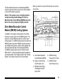
Initial Drive Information
Transmission
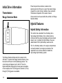
Range Selection Mode
Press the plus/minus buttons, located on the
steering column shift lever, to select the desired range
of gears for current driving conditions. See Automatic
Transmission Operation in the owner manual.
Cruise control can be used while the vehicle is in Range
Selection Mode.
Hybrid Features
Hybrid Safety Information
This vehicle has a standard 12-volt battery and a
high-voltage hybrid battery. Only a trained service
technician with the proper knowledge and tools should
inspect, test, or replace the hybrid battery. See your
dealer/retailer if the hybrid battery needs service.
The 12-volt battery cables, in the engine compartment,
are clearly labeled. In emergency situations, first
responders can cut those cables to disable the
high-voltage hybrid battery system.
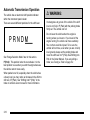
The Range Selection Mode switch is located on the
shift lever. To enable the Range Selection feature, move
the column shift lever to the M (Manual) position. The
current range will appear next to the M. This is the
highest attainable range with all lower gears accessible.
As an example, when 3 (Third) gear is selected, 1 (First)
through 3 (Third) gears are available.
1-2
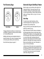
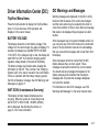
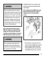
Fuel Economy Gage
Automatic Engine Start/Stop Feature
Start the engine as you would any other engine. See
“Starting the Engine” in the owner manual for more
information on starting. The hybrid system provides
very quiet engine starting. If pulling a trailer with trailer
brakes, see Towing a Trailer on page 5‑2 for more
information.
Auto Stop
The vehicle has an Auto Stop feature. After a
successful engine start, the engine may turn off
and operate in the Auto Stop mode.
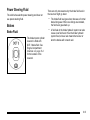
United States
Canada
This gage indicates fuel efficiency. To obtain the best
fuel efficiency, operate the vehicle so that the indicator
is in the high efficiency band.
Modifying both braking and acceleration behavior to
keep the indicator in the center of the gage will result
in the best system efficiency and fuel economy.
See Fuel Economy Gage on page 4‑5.
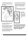
Keep your foot firmly on the brake pedal until you are
ready for the vehicle to move.
Engine OFF and AUTO STOP modes are indicated on
the tachometer display. When the tachometer needle
indicates OFF, the engine is not running and will remain
off until the ignition key is placed in the START position
or a remote vehicle start is performed. When the
tachometer needle indicates AUTO STOP, the hybrid
system is on, the engine is not running, but may Auto
Start at any time without notice. See Tachometer on
page 4‑4 for more information.
A chime will sound if the driver door is opened while in
Auto Stop as a reminder that the ignition switch is not in
the LOCK/OFF position. Always turn the ignition switch
to LOCK/OFF and remove the key from the ignition
switch when exiting the vehicle.
1-3
Auto Start
The vehicle also has an Auto Start feature. The engine
will remain off while in Auto Stop mode until vehicle
conditions require the engine to run. The near-instant
starting of the engine from Auto Stop mode is called
Auto Start.
EV Mode
The vehicle also has an EV mode which uses only
the electric motor to move the vehicle. With light
acceleration, the vehicle will drive in EV mode. EV
mode is unavailable when the vehicle is out of fuel.
See Starting the Vehicle in the Two‐Mode Hybrid
supplement to the owner manual.
Regenerative Braking
Regenerative braking enables the electric drive motor to
operate as a generator when coasting or braking.
Energy from the moving vehicle recharges the hybrid
battery.
The hydraulic disc brakes work with the regenerative
braking to insure effective braking.
The braking system is computer controlled and blends
the regenerative braking with the conventional hydraulic
disc brakes to meet any requirements for deceleration.
Because the controller applies the hydraulic brakes
through its high pressure accumulator, you may
1-4
occasionally hear the motor driven pump when it
recharges the system. This is normal. In the event of a
controller problem, the brake pedal may be harder to
push and the stopping distance may be longer.
See Regenerative Braking, Warning Lights, Gages, and
Indicators and Driver Information Center (DIC) in the
owner manual.
Battery
This vehicle has a standard 12-volt battery and a
high-voltage hybrid battery. When a new standard
12-volt battery is needed, see your dealer/retailer for
one that has the replacement number shown on the
original battery's label.
Only a trained service technician with the proper
knowledge and tools should inspect, test, or replace the
hybrid battery. See your dealer/retailer if the hybrid
battery needs service. See Battery on page 6‑17.
Service
Never try to do your own service on hybrid components.
You can be injured and the vehicle can be damaged if
you try to do your own service work. Service and repair
of these hybrid components should only be performed
by a trained service technician with the proper
knowledge and tools. See Doing Your Own Service
Work on page 6‑2.
Section 2
Seats and Restraint System
Rear Seats . . . . . . . . . . . . . . . . . . . . . . . . . . . . . . . . . . . . . . . . . 2-2
Rear Seat Operation (Hybrid Full Bench) . . . . . . . 2-2
Restraint System Check . . . . . . . . . . . . . . . . . . . . . . . . . . . 2-2
Replacing Restraint System Parts After
a Crash . . . . . . . . . . . . . . . . . . . . . . . . . . . . . . . . . . . . . . . 2-2
2-1
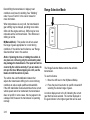
Rear Seats
Restraint System Check
Rear Seat Operation (Hybrid Full
Bench)
Replacing Restraint System Parts
After a Crash
Folding Rear Seat
If an airbag inflates or the vehicle has been in a crash,
the vehicle's sensing system may command the
automatic hybrid battery disconnect to open. The
battery will disconnect. The hybrid battery will be off and
the vehicle will not start. The airbag readiness light and/
or SERVICE HYBRID SYSTEM warning message may
come on in the driver information center. See “Airbag
Readiness Light” in the owner manual and Driver
Information Center (DIC) on page 4‑11 for more
information.
Notice: Folding a rear seat with the safety belts
still fastened may cause damage to the seat or the
safety belts. Always unbuckle the safety belts and
return them to their normal stowed position before
folding a rear seat.
Make sure that nothing is on the seat.
To fold the seat, slowly pull the seat cushion up.
To return the seat to the normal seating position, slowly
pull the seat cushion down.
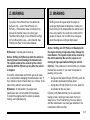
{ WARNING:
A safety belt that is improperly routed, not
properly attached, or twisted will not provide the
protection needed in a crash. The person wearing
the belt could be seriously injured. After raising
the rear seatback, always check to be sure that
the safety belts are properly routed and attached,
and are not twisted.
2-2
To operate the vehicle, the automatic hybrid battery
disconnect must be serviced by a qualified service
technician and sensing system parts will need to be
replaced. Have the vehicle serviced right away.
Section 3
Features and Controls
Storage Areas . . . . . . . . . . . . . . . . . . . . . . . . . . . . . . . . . . . . . . 3-2
Tonneau Cover (Hard Tonneau) . . . . . . . . . . . . . . . . . 3-2
Tonneau Cover (Soft Tonneau) . . . . . . . . . . . . . . . . . . 3-7
Starting and Operating Your Vehicle . . . . . . . . . . . .
Starting the Vehicle . . . . . . . . . . . . . . . . . . . . . . . . . . . .
Automatic Transmission Operation . . . . . . . . . . . . .
Engine Coolant Heater . . . . . . . . . . . . . . . . . . . . . . . . .
Regenerative Braking . . . . . . . . . . . . . . . . . . . . . . . . . .
Running the Vehicle While Parked . . . . . . . . . . . . .
3-14
3-14
3-16
3-19
3-21
3-21
3-1
Storage Areas
Tonneau Cover (Hard Tonneau)
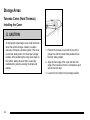
Installing the Cover
{ CAUTION:
An improperly stored cargo cover could be thrown
about the vehicle during a collision or sudden
maneuver. Someone could be injured. If the cover
is removed, always store it in the proper storage
location. After positioning the cargo cover back on
the vehicle, always be sure that it is securely
reattached by properly securing the straps and
latches.
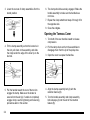
1. Position the tonneau cover onto the top of the
pickup box with the locator tabs positioned into
the front stake pockets.
2. Align the front edge of the cover with the front
edge of the bed rail so that it is centered on each
side of the truck bed.
3. Lower the front clamp from its storage position.
3-2
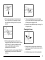
4. Tilt the clamp assembly so that the locator is in
the slot, pull down on the assembly, and slide
the clamp under the edge of the inner lip of the
bed rail.
7. There are locking features on the front clamps
only. With the handle in the clamped position, push
the locking tab to engage the lock.
8. Repeat the clamp attachment steps 3 through 7 for
the opposite side.
Closing the Cover
5. Pull the handle toward the rear of the truck to
engage the clamp. Make sure the locator is secure
into the slot (A). If unable to completely engage
clamp, see the tightening and loosening
procedures later in this section.
6. The clamp should be securely engaged. Shake the
handle assembly to make sure the handle does
not move.
1. Release both the retention straps located on the
top of the cover behind the cab and press into the
stored position.
2. Unfold the tonneau cover to the closed position.
3-3
3. Lower the rear set of clamp assemblies from the
stored position.
6. The clamp should be securely engaged. Shake the
handle assembly to make sure the handle does
not move.
7. Repeat the clamp attachment steps 3 through 6 for
the opposite side.
8. Close the endgate.
Opening the Tonneau Cover
1. Turn both of the rear handles inward to release
compression.
4. Tilt the clamp assembly so that the locator is in
the slot, pull down on the assembly, and slide
the clamp under the edge of the inner lip on the
bed rail.
2. Pull the clamp down and turn the assemblies to
disengage them from the lip of the pickup box.
5. Pull the handle toward the rear of the truck to
engage the clamp. Make sure the locator is
secured into the slot (A). If unable to completely
engage clamp, see the tightening and loosening
procedures later in this section.
4. Align the clamp assembly bolt (A) with the
retention feature (B).
3-4
3. Open the cover to expose the handles.
5. Turn the handle assembly and clamp assembly
bolt sideways (A) into the slot of the retention
feature (B).
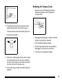
Removing the Tonneau Cover
1. Open the cover by following the procedure
described previously, under “Opening the
Tonneau Cover”.
6. The handle should lie flat on the panel with the
handles facing inward. Press firmly to secure.
This step must be done before stowing the cover.
7. Fold the cover forward.
2. Disengage the locking tabs, located on the front
handles, by pulling them rearward.
3. Turn the handles inward to release.
4. Pull the clamp down and turn the assembly to
disengage it from the lip of the truck box.
5. Turn the cover to expose the handles.
8. Remove the retaining strap from the bow. Connect
the retention buckle ends. One end is located on
the front of the tonneau cover behind the cab and
the other end is on the tonneau cover
9. Pull on each strap to make sure both buckles are
attached.
3-5
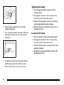
Tightening the Clamp
1. Push the handle forward to release it from the
clamped position.
2. Disengage the clamp from the inner edge of the
bed rail and slide the assembly inward.
3. Adjust the clamp height on the bolt by turning the
entire clamp assembly counter-clockwise.
6. Align the clamp assembly bolt (A), with the
retention feature (B).
7. Turn the handle assembly sideways by tilting the
assembly bolt (A) into the slot of the retention
feature (B).
4. Attach the clamps as indicated in steps 4 and 5 of
Installing the Cover.
Loosening the Clamp
1. Return the handle to the fully disengaged position.
2. Disengage the clamp from the inner edge of the
bed rail and slide the assembly inward.
3. Adjust the clamp height by turning the entire clamp
assembly clockwise.
4. Reattach the clamps as indicated in steps 4 and 5
of Installing the Cover.
8. The handle should lie flat on the panel with the
handles facing inward. Press firmly to secure.
9. Remove the tonneau cover from the vehicle.
3-6
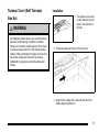
Tonneau Cover (Soft Tonneau)
Side Rail
{ WARNING:
An improperly stored cargo cover could be thrown
about the vehicle during a collision or sudden
maneuver. Someone could be injured. If the cover
is removed, always store it in the proper storage
location. After positioning the cargo cover back on
the vehicle, always be sure that it is securely
reattached by properly securing the straps and
latches.
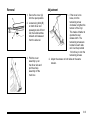
Installation
1. The adjuster screw end
of each side rail should
point in the direction of
the cab.
2. Place each side rail on top of the truck box.
3. Align the front edge of the side rail with the front
inside edge of pickup box.
3-7
Clamp
3. If the pickup box
has molded bed rail
protectors (A), remove
the insert (C) from the
outer groove on the
clamp, and position
the clamp on the side
rail (B) using the outer
groove (D).
Installation
4. Slide the inner
clamp (B) into the
outer clamp (A).
5. Turn the latch (C) onto
the outer clamp.
1. Position three outer clamps (A), on each side rail.
The positions on the siderails are marked CLAMP.
2. Position the grooves of
the clamps on the side
rails (A) using the
center groove (B).
3-8
6. Tighten the clamp by turning the latch (C) toward
the side rail. Make sure there is no gap between
the rubber clamp pad and the side rail.
7. If the truck box has a molded bed rail protector,
insert the latch into the top notch on the inner
clamp.
8. Clean the vehicle's painted surface below the pull
strap using a 50/50 mixture of rubbing alcohol and
tap water.
9. Remove the paper from the provided clear tape
strip and apply to the painted surface below the
pull strap.
Adjustment
If there is excessive sideways movement of the
crossrails, move and re-install the clamps on the
loose areas using the inner groove of the clamp.
3-9
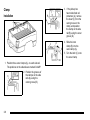
Cover
Installation
2. Verify the gap between the adjuster screws and
pivot mounts is 3/16 in. Adjust if needed.
1. Place the cover assembly into the front pivot
mounts firmly against the adjustment screws.
3-10
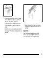
3. Loosen the wing bolt (A), then slide the latch
outboard into the side rail. Tighten down the wing
bolt (A). Do this on both sides. Both latches must
remain engaged and the wing bolts tightened while
the cover is on the vehicle. Make sure by lifting up
on each end of the cover assembly.
4. Unbuckle both straps and roll the cover out. Make
sure that each bow falls in between the side rails.
If the bows do not fit between the side rails, verify
that the clamps are pushed fully outboard without
any gaps between the clamp pad and pickup box.
If additional clearance is required, remove the
clamp closest to the interference. Remove the
orange strip to allow access to the outer slot of the
upper clamp. Reinstall the clamp using the outer
groove of the upper clamp. If bows are too loose,
adjust the clamp closest to the bow with the
excessive clearance to the inner groove of the
upper clamp.
3-11
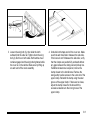
7. Secure the buckles by
folding them once, then
slide them under the
cord located on the
cover.
Secure in Open Position
5. When the cover is rolled out, place the rear rail
into the rear pivot mounts. Firmly press down
on each side of the cover, until the latches are
secured into the side rails. If latch is too tight,
loosen the tension adjustment screws. If the latch
is not securely holding the rear rail, tighten the
tension adjustment screws. Only the driver's side
has a latch.
6. Secure the driver side Velcro® of the cover to the
side rail. Then pull the cover tight across the bed
and fasten the Velcro® on the passenger side.
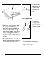
1. To open the cover,
open tailgate and push
down on the cover. The
pull back on pull strap.
2. From the drivers side, roll the cover up tightly.
3. When the cover is rolled up, buckle both tie-down
straps. Pull both straps tight.
3-12
Removal
Adjustment
1. Secure the cover (A)
into the open position.
2. Loosen wing bolts (B)
on both driver and
passenger side of front
rail, then slide latches
inboard until released
from the side rail.
3. Pick the cover
assembly up on
the driver side and
pull the whole
assembly off the
truck box.
1. If the cover is too
loose, turn the
tensioning screw
clockwise to tighten the
tension of the vinyl.
This makes it harder to
operate the rear
release latch. The
tensioning screws are
located on each side
rail. Use the provided
1/4 inch key to turn the
tensioning screws.
2. Adjust the screws on both sides to the same
tension.
3-13
Starting and Operating Your
Vehicle
Starting the Vehicle
Auto Stop
The vehicle has an Auto Stop feature. After a
successful engine start, the engine may turn off and
operate in the Auto Stop mode. Some of the vehicle
conditions that allow the engine to stop running and
enter the Auto Stop mode are:
{ WARNING:
.
Ignition switch is in the ON/RUN position.
.
The hood is closed.
Exiting the vehicle, without first shifting into
P (Park), may cause the vehicle to move, and
you or others can be seriously injured. Because
the vehicle has the Automatic Engine Start/Stop
feature, the vehicle’s engine might seem to be
shut off when you come to a complete stop.
However, once the brake pedal is released, the
vehicle can move. The vehicle’s engine can also
restart at any time.
.
The gear selector is in P (Park), R (Reverse),
N (Neutral) or D (Drive).
.
The hybrid battery is at an acceptable state of
charge.
.
The hybrid battery voltage, temperature or power
limits are not exceeded. In very hot conditions,
Auto Stop may be unavailable until the hybrid
battery has cooled.
.
The engine is at operating temperature.
.
The vehicle may enter Auto Stop after a remote
vehicle start.
Shift to P (Park) and turn the ignition to LOCK/
OFF, before exiting the vehicle.
Start the engine as you would any other engine. See
“Starting the Engine” in the owner manual for more
information on starting. If pulling a trailer with trailer
brakes, see Towing a Trailer on page 5‑2 for more
information.
3-14
If you are on an incline, the hybrid drive motor can help
keep the vehicle from rolling backwards, even if the
engine is in Auto Stop.
With your foot off the brake and the vehicle on level
ground, the hybrid drive motor may cause the vehicle to
roll slowly forward, even when the engine is in
Auto Stop.
Keep your foot firmly on the brake pedal until you are
ready for the vehicle to move.
.
The hybrid battery voltage, temperature or power
limits are exceeded.
Engine OFF and AUTO STOP modes are indicated on
the tachometer display. When the tachometer needle
indicates OFF, the engine is not running and will remain
off until the ignition key is placed in the START position
or a remote vehicle start is performed. When the
tachometer needle indicates AUTO STOP, the hybrid
system is on, the engine is not running, but may Auto
Start at any time without notice. See Tachometer on
page 4‑4 for more information.
.
A remote vehicle start has been requested.
.
The engine is not at operating temperature.
.
Acceleration demands require the use of the
engine.
A chime will sound if the driver door is opened while in
Auto Stop as a reminder that the ignition switch is not in
the LOCK/OFF position. Always turn the ignition switch
to LOCK/OFF and remove the key from the ignition
switch when exiting the vehicle.
Auto Start
The vehicle also has an Auto Start feature. The engine
will remain off while in Auto Stop mode until vehicle
conditions require the engine to run. The near-instant
starting of the engine from Auto Stop mode is called
Auto Start. Some of the vehicle conditions that may
cause the engine to Auto Start are:
.
The hood is opened.
.
The gear selector is in M (Manual Mode).
.
The hybrid battery state of charge is too low.
EV Mode
The vehicle also has an Electric Vehicle (EV) mode
which uses only the electric motor to move the vehicle.
With light acceleration, the vehicle will drive in EV
mode. EV mode is unavailable when the vehicle is
out of fuel.
If increased acceleration is required, or the vehicle
reaches approximately 40 km/h (30 mph), the engine
will start automatically. The engine shuts off at speeds
below 40 km/h (25 mph) unless the transmission is in
M (Manual Mode) or Auto Stop is disabled.
During heavy acceleration, both the engine and
hybrid electric motors supply power. A sensation
similar to a transmission gear change can be felt
as the transmission changes modes. Engine RPM
may remain above 4,000 RPM for a longer period
during hard acceleration.
3-15
Automatic Transmission Operation
The vehicle has an electronic shift position indicator
within the instrument panel cluster.
There are several different positions for the shift lever.
See “Range Selection Mode” later in this section.
P (Park) : This position locks the rear wheels. It is the
best position to use when you start the engine because
the vehicle cannot move easily.
When parked on a hill, especially when the vehicle has
a heavy load, you may notice an increase in the effort to
shift out of P (Park). See “Shifting Into P (Park)” in the
Index of vehicle's owner manual for more information.
3-16
{ WARNING:
It is dangerous to get out of the vehicle if the shift
lever is not fully in P (Park) with the parking brake
firmly set. The vehicle can roll.
Do not leave the vehicle when the engine is
running unless you have to. If you have left the
engine running, the vehicle can move suddenly.
You or others could be injured. To be sure the
vehicle will not move, even when you are on fairly
level ground, always set the parking brake and
move the shift lever to P (Park). See Shifting Into
Park in the Owner Manual. If you are pulling a
trailer, see Towing a Trailer on page 5‑2.
{ WARNING:
{ WARNING:
If you have Four-Wheel Drive, the vehicle will
be free to roll — even if the shift lever is in
P (Park) — if the transfer case is in Neutral. So,
be sure the transfer case is in a drive gear,
Two-Wheel Drive High or Four-Wheel Drive High
or Four-Wheel Drive Low — not in Neutral. See
“Shifting Into Park” in the Owner Manual.
Shifting into a drive gear while the engine is
running at high speed is dangerous. Unless your
foot is firmly on the brake pedal, the vehicle could
move very rapidly. You could lose control and hit
people or objects. Do not shift into a drive gear
while the engine is running at high speed.
R (Reverse) : Use this gear to back up.
Notice: Shifting to R (Reverse) while the vehicle is
moving forward could damage the transmission.
The repairs would not be covered by the vehicle
warranty. Shift to R (Reverse) only after the vehicle
is stopped.
To rock the vehicle back and forth to get out of snow,
ice, or sand without damaging the transmission, see “If
Your Vehicle is Stuck in Sand, Mud, Ice, or Snow” in the
Index of the vehicle's owner manual.
N (Neutral) : In this position, the engine and
transmission are not connected with the wheels.
To restart the engine when the vehicle is already
moving, use N (Neutral) only.
Notice: Shifting out of P (Park) or N (Neutral) with
the engine running at high speed may damage the
transmission. The repairs would not be covered by
the vehicle warranty. Be sure the engine is not
running at high speed when shifting the vehicle.
D (Drive) : This position is for normal driving. It provides
the best fuel economy. If you need more power for
passing, and you are:
.
Going less than about 35 mph (55 km/h), push the
accelerator pedal about halfway down.
.
Going about 35 mph (55 km/h) or more, push the
accelerator all the way down.
D (Drive) or M (Manual Mode) can be used when
towing a trailer, carrying a heavy load, driving on
steep hills, or for off-road driving. You may want to
shift the transmission to a lower gear selection if the
transmission shifts too often.
3-17
Downshifting the transmission in slippery road
conditions could result in skidding. See “Skidding”
under “Loss of Control” in the owner manual for
more information.
Range Selection Mode
When temperatures are very cold, the transmission's
gear shifting may be delayed, providing more stable
shifts until the engine warms up. Shifts may be more
noticeable with a cold transmission. This difference in
shifting is normal.
M (Manual Mode) : This position lets drivers select
the range of gears appropriate for current driving
conditions. If the vehicle has this feature, see “Range
Selection Mode” later in this section.
Notice: Spinning the tires or holding the vehicle in
one place on a hill using only the accelerator pedal
may damage the transmission. The repair will not be
covered by the vehicle warranty. If you are stuck, do
not spin the tires. When stopping on a hill, use the
brakes to hold the vehicle in place.
The vehicle has a shift stabilization feature that
adjusts the transmission shifting to the current driving
conditions to reduce rapid upshifts and downshifts.
If the shift stabilization feature determines that a current
vehicle speed cannot be maintained, the transmission
does not upshift. In some cases, this may appear to be
a delayed shift, however the transmission is operating
normally.
3-18
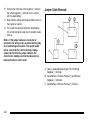
The Range Selection Mode controls the vehicle's
transmission.
To use this feature:
1. Move the shift lever to the M (Manual Mode).
2. Press the plus/minus button to upshift or downshift
selecting the desired range of gears.
A number displays next to the M, indicating the current
gear that has been selected. The number displayed in
the gear indicator is the highest gear that can be used.
The vehicle can automatically shift to lower gears as
it adjusts to driving conditions. When 3 (Third) is
selected, 1 (First) through 3 (Third) gears are
automatically shifted by the vehicle, but 4 (Fourth)
cannot be used until it is selected.
In the M1 gear range, effective engine braking occurs at
speeds above 10 mph (16 km/h).
The Range Selection Mode controls the vehicle and
engine speed while driving down a hill or towing a
trailer, by allowing you to select a desired range
of gears.
Cruise control can be used while using the Range
Selection Mode.
When you move the shift lever into M, the transmission
will default to M4. In this gear range, effective engine
braking occurs at speeds above 45 mph (72 km/h).
Pushing the minus (−) button on the shift lever reduces
the gear range.
In the M3 gear range, effective engine braking occurs at
speeds above 35 mph (56 km/h).
In the M2 gear range, effective engine braking occurs at
speeds above 25 mph (40 km/h).
When operating in M (Manual Mode), Auto Stop is
disabled. For better vehicle efficiency, operate the
vehicle in D (Drive) not M (Manual Mode).
Engine Coolant Heater
The engine coolant heater can provide easier starting
and better fuel economy during engine warm-up in cold
weather conditions at or below −18°C (0°F). Vehicles
with an engine heater should be plugged in at least
four hours before starting. An internal thermostat in
the plug-end of the cord may exist which will prevent
engine coolant heater operation at temperatures
above −18°C (0°F).
3-19
To Use the Engine Coolant Heater
1. Turn off the engine.
2. Open the hood and unwrap the electrical cord. The
cord is secured to a wiring harness between the
engine and the Hybrid Auxiliary Underhood Fuse
Block with a clip. Carefully remove the wire tie
which secures the electrical cord. Do not cut the
electrical cord.
3. Plug the cord into a normal, grounded 110-volt AC
outlet.
{ WARNING:
Plugging the cord into an ungrounded outlet could
cause an electrical shock. Also, the wrong kind of
extension cord could overheat and cause a fire.
You could be seriously injured. Plug the cord into
a properly grounded three-prong 110-volt AC
outlet. If the cord will not reach, use a heavy-duty
three-prong extension cord rated for at least
15 amps.
4. Before starting the engine, be sure to unplug and
store the cord as it was before to keep it away from
moving engine parts. If you do not, it could be
damaged.
The length of time the heater should remain plugged in
depends on several factors. Ask a dealer/retailer in the
area where you will be parking the vehicle for the best
advice on this.
3-20
Regenerative Braking
Running the Vehicle While Parked
Regenerative braking is a hybrid technology that
enables the electric drive motor to operate as a
generator when coasting or braking. Energy from the
moving vehicle recharges the hybrid battery.
It is better not to park with the engine running. But if you
ever have to, here are some things to know.
The hydraulic disc brakes work with the regenerative
braking to insure effective braking, such as when a high
braking demand is requested.
The braking system is computer controlled and blends
the regenerative braking with the conventional hydraulic
disc brakes to meet any requirements for deceleration.
The controller interprets the braking request and uses
regenerative braking, conventional hydraulic braking or
a combination of both as necessary. Because the
controller applies the hydraulic brakes through its high
pressure accumulator, you may occasionally hear the
motor driven pump when it recharges the system. This
is normal.
In the event of a controller problem, the brake pedal
may be harder to push and the stopping distance may
be longer.
{ WARNING:
Exiting the vehicle, without first shifting into
P (Park), may cause the vehicle to move, and you
or others can be seriously injured. Because the
vehicle has the Automatic Engine Start/Stop
feature, the vehicle’s engine might seem to be
shut off when you come to a complete stop.
However, once the brake pedal is released, the
vehicle can move. The vehicle’s engine can also
restart at any time.
Shift to P (Park) and turn the ignition to LOCK/
OFF, before exiting the vehicle.
Follow the proper steps to be sure the vehicle will not
move. See “Shifting Into Park” in the owner manual for
more information.
If pulling a trailer, see Towing a Trailer on page 5‑2 for
more information.
3-21
2 NOTES
3-22
Section 4
Climate Controls . . . . . . . . . . . . . . . . . . . . . . . . . . . . . . . . . . .
Warning Lights, Gages, and Indicators . . . . . . . . . . .
Instrument Panel Cluster . . . . . . . . . . . . . . . . . . . . . . . .
Tachometer . . . . . . . . . . . . . . . . . . . . . . . . . . . . . . . . . . . . .
Charging System Light . . . . . . . . . . . . . . . . . . . . . . . . . .
Fuel Economy Gage . . . . . . . . . . . . . . . . . . . . . . . . . . . .
Brake System Warning Light . . . . . . . . . . . . . . . . . . . .
Antilock Brake System (ABS) Warning Light . . . .
StabiliTrak® Indicator Light . . . . . . . . . . . . . . . . . . . . . .
Instrument Panel
4-2
4-3
4-3
4-4
4-4
4-5
4-5
4-7
4-7
Engine Coolant Temperature Gage . . . . . . . . . . . . . 4-8
Oil Pressure Gage . . . . . . . . . . . . . . . . . . . . . . . . . . . . . . 4-8
Oil Pressure Light . . . . . . . . . . . . . . . . . . . . . . . . . . . . . . . 4-9
Fuel Gage . . . . . . . . . . . . . . . . . . . . . . . . . . . . . . . . . . . . . 4-10
Driver Information Center (DIC) . . . . . . . . . . . . . . . . . . 4-11
DIC Warnings and Messages . . . . . . . . . . . . . . . . . . 4-11
Audio System(s) . . . . . . . . . . . . . . . . . . . . . . . . . . . . . . . . . . 4-13
Navigation/Radio System . . . . . . . . . . . . . . . . . . . . . . 4-13
4-1
Climate Controls
For more information on the vehicle's climate control
system, see “Climate Control System” in the owner
manual.
Electric Air Conditioning Compressor
This hybrid vehicle has a electrically powered air
conditioning compressor. This allows for continuous air
conditioning operation and passenger comfort, even
while the hybrid engine cycles on and off.
When operating the climate control system, select the
AUTO mode and the desired temperature setting. The
climate control system automatically adjusts the fan
speed and airflow direction. The climate control system
continues to adjust the climate control settings chosen
for best use of electrical power.
4-2
At mild temperatures, select a warmer air conditioner
temperature or turn the air conditioner off to get
maximum fuel economy. Continuous air conditioner use
can cause the vehicle to Auto Start more frequently.
During hot weather, driving with the windows closed and
the air conditioner set to Auto mode, will result in better
Hybrid system performance.
Some noise may be heard occasionally from the
compressor, especially when air conditioning use is
high and the engine has turned off.
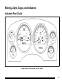
Warning Lights, Gages, and Indicators
Instrument Panel Cluster
United States version shown, Canada similar
4-3
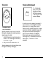
Tachometer
Charging System Light
This 12 V battery light
comes on briefly when
the ignition is turned to
ON/RUN, but the engine
is not running, as a check
to show it is working.
United States Version
shown, Canada similar
When the gas engine is off and the key is in the ON/
RUN position, the position of the tachometer indicator
shows the state of the vehicle:
.
AUTO STOP position indicates that the vehicle is
still able to move and the engine could restart, by
an Auto Start, at any time.
.
OFF position indicates that the vehicle is off.
When the engine is on, the tachometer indicator shows
the engine's revolutions per minute (rpm).
4-4
It should go out once the engine has been started. If it
stays on, or comes on while driving, there could be a
problem with the 12 V charging system. Have the
vehicle serviced by your dealer/retailer. A 12 V charging
system Driver Information Center (DIC) message may
also appear. See DIC Warnings and Messages on
page 4‑11 for more information. This light could
indicate that there are electrical problems. Have it
checked right away. If a short distance must be driven
with the light on, be certain to turn off all the
accessories.
Fuel Economy Gage
White Zones : Decreased fuel efficiency driving
behavior makes the indicator display in the two white
zones. The indicator in the white zone on the left side of
the gage indicates decreased fuel efficiency with a large
amount of decelerations. The indicator in the white zone
on the right side of the gage indicates decreased fuel
efficiency with a large amount of accelerations.
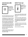
Brake System Warning Light
United States
Canada
This gage shows displays how efficiently the vehicle is
being driven.
There are three zones on the drive efficiency gage.
Green Zone : Fuel efficient driving behavior makes the
indicator display in the green zone on the gage.
With the ignition in ON/RUN, the brake system warning
light comes on when the parking brake is set. If the
vehicle is driven with the parking brake engaged, a
chime sounds when the vehicle speed is greater than
5 mph (8 km/h).
The vehicle's hydraulic brake system is divided into
two parts. If one part is not working, the other part can
still work and stop the vehicle. For good braking,
though, both parts need to be working well.
If the warning light comes on and a chime sounds there
could be a brake problem. Have the brake system
inspected right away.
4-5
This light also comes on due to low brake fluid. See the
owner manual for more information.
{ WARNING:
The brake system might not be working properly if
the brake system warning light is on. Driving with
the brake system warning light on can lead to a
crash. If the light is still on after the vehicle has
been pulled off the road and carefully stopped,
have the vehicle towed for service.
United States
Canada
This light should come on briefly when the ignition key
is turned to ON/RUN. If it does not come on then, have
it fixed so it will be ready to warn if there is a problem.
4-6
If the light comes on while driving, pull off the road and
stop carefully. The pedal might be harder to push or can
go closer to the floor. It may take longer to stop. If the
light does not go out, have the vehicle towed for
service. See Towing Your Vehicle on page 5‑2.
Antilock Brake System (ABS)
Warning Light
For vehicles with the
Antilock Brake System
(ABS), this light comes
on briefly when the engine
is in ON/RUN.
That is normal. If the light does not come on then, have
it fixed so it will be ready to warn if there is a problem.
If the ABS light stays on, turn the ignition off, if the light
comes on while driving, stop as soon as it is safely
possible and turn the ignition off. Then start the engine
again to reset the system. If the ABS light still stays on,
or comes on again while driving, the vehicle needs
service. If the regular brake system warning light is not
on, the vehicle still has brakes, but not antilock brakes.
If the regular brake system warning light is also on, the
vehicle does not have antilock brakes and there is a
problem with the regular brakes. See Brake System
Warning Light on page 4‑5.
StabiliTrak® Indicator Light
For vehicles with
StabiliTrak, this warning
light comes on briefly
when the ignition is in
ON/RUN.
If it does not, have the vehicle serviced by your dealer/
retailer. If the system is working normally the indicator
light goes off.
If the light comes on and stays on while driving, there
could be a problem with the StabiliTrak system and the
vehicle might need service. When this warning light is
on, the StabiliTrak system is off and does not limit
wheel spin.
The light flashes if the system is active and is working
to assist the driver with directional control of the vehicle
in difficult driving conditions.
See the owner manual for more information.
For vehicles with a Driver Information Center (DIC), see
DIC Warnings and Messages on page 4‑11 for all
brake related DIC messages.
4-7
Engine Coolant Temperature Gage
United States
Canada
This gage shows the engine coolant temperature.
It also provides an indicator of how hard the vehicle is
working. During a majority of the operation, the gage
reads 210°F (100°C) or less. If a load is being pulled
or going up hills, it is normal for the temperature to
fluctuate and go over the 235°F (113°C) mark. However,
if the gage reaches the 260°F (125°C) mark, it indicates
that the cooling system is working beyond its capacity.
Oil Pressure Gage
United States
Canada
The oil pressure gage shows the engine oil pressure
in psi (pounds per square inch) when the engine is
running. Canadian vehicles indicate pressure in
kPa (kilopascals).
Oil pressure should be 29 to 80 psi (200 to 550 kPa).
In certain situations, such as long extended idles on
hot days, it could read as low as 15 psi (105 kPa) and
still be considered normal.
A reading in the low pressure zone may be caused
by a dangerously low oil level or some other problem
causing low oil pressure. Check the oil as soon as
possible.
4-8
{ WARNING:
Do not keep driving if the oil pressure is low. The
engine can become so hot that it catches fire.
Someone could be burned. Check the oil as soon
as possible and have the vehicle serviced.
Notice: Lack of proper engine oil maintenance
can damage the engine. The repairs would not be
covered by the vehicle warranty. Always follow the
maintenance schedule in this manual for changing
engine oil.
AUTO STOP
When the engine goes into Automatic Engine Stop, the
oil pressure gage drops to zero when the tachometer
is at the AUTO STOP position. This is normal and oil
pressure returns to the normal operating range once
the engine starts.
Oil Pressure Light
{ WARNING:
Do not keep driving if the oil pressure is low. The
engine can become so hot that it catches fire.
Someone could be burned. Check the oil as soon
as possible and have the vehicle serviced.
Notice: Lack of proper engine oil maintenance
can damage the engine. The repairs would not be
covered by the vehicle warranty. Always follow the
maintenance schedule in this manual for changing
engine oil.
This light comes on briefly
as a check it works, when
the ignition is in ON/RUN.
If it does not, have the
vehicle serviced.
See Starting the Vehicle on page 3‑14 for more
information.
AUTO STOP displays in the Driver Information Center
(DIC) when the vehicle speed is zero. See DIC
Warnings and Messages on page 4‑11 for more
information.
4-9
If the light comes on and stays on, it means that oil is
not flowing through the engine properly. The vehicle
could be low on oil and might have some other system
problem.
During an AUTO STOP there is zero oil pressure, but
this light will not come on.
Listed are four situations that may occur with the fuel
gage, none of these indicate a problem:
.
At the gas station, the fuel pump shuts off before
the gage reads F (full).
.
It takes a little more or less fuel to fill up than the
fuel gage indicated. For example, the gage may
have indicated the tank was half full, but it actually
took a little more or less than half the tank's
capacity to fill the tank.
.
The gage moves a little while turning a corner or
while accelerating.
.
The gage does not go back to E (empty) when the
ignition is turned off.
Fuel Gage
United States
Canada
When the ignition is on, the fuel gage shows
approximately how much fuel is left in the fuel tank. An
arrow on the fuel gage indicates the side of the vehicle
the fuel door is on. The gage first indicates E (empty)
before the vehicle is out of fuel, but the vehicle should
be refueled as soon as possible.
4-10
Driver Information Center (DIC)
DIC Warnings and Messages
Trip/Fuel Menu Items
Warning messages are displayed on the DIC to notify
the driver that the status of the vehicle has changed
and that some action may be needed by the driver to
correct the condition. If there is more than one message
that needs to be displayed they will appear one after
another.
Press the trip/fuel button to display the Trip/Fuel Menu
items. For more items see “DIC Operation and
Displays” in the owner manual.
BATTERY VOLTAGE
This display shows the current battery voltage. If the
voltage is in the normal range, the value will display. For
example, the display may read BATTERY VOLTAGE
13.2 VOLTS. If the voltage is high or low, the display will
read HIGH or LOW. Your vehicle's charging system
regulates voltage based on the state of the battery.
The battery voltage may fluctuate when viewing this
information on the DIC. This is normal. See “Charging
System Light” in the owner manual for more information.
If there is a problem with the battery charging system,
the DIC will display a message. See DIC Warnings and
Messages on page 4‑11.
INST ECON (Instantaneous Economy)
Some messages may not require immediate action, but
you can press any of the DIC buttons on the instrument
panel or the trip odometer reset stem to acknowledge
that you received the messages and to clear them from
the display.
Some messages cannot be cleared from the DIC
display because they are more urgent. These
messages require action before they can be cleared.
You should take any messages that appear on the
display seriously and remember that clearing the
messages will only make the messages disappear,
not correct the problem.
For information on other DIC messages, see “DIC
Warnings and Messages” in the owner manual Index.
This display normally shows instantaneous fuel
economy. When the vehicle is in Auto Stop mode
AUTO STOP or INST ECON = 99 MPG (l/00km)
will be displayed. See Starting the Vehicle on
page 3‑14 for more information.
4-11
HOOD OPEN
If the hood is not fully closed or there is a problem with
the hood switch, this message will be displayed. Close
the hood to clear the message. If the HOOD OPEN
message continues to be displayed after verifying the
hood is closed, you should have the hood switch
serviced. Failure to service the hood switch properly
can result in an Auto Start condition.
Warning Light” in the owner manual Index. Driving with
this message on could drain the battery. Have the
electrical system checked as soon as possible.
SERVICE BRAKE SYSTEM
Auto Stops will be disabled when this message is
displayed. If the vehicle is in auto stop mode when this
message appears, the engine will instantly start.
This message will be displayed if there is a problem
with the brake system. You will still be able to brake, but
it will be noticeably more difficult. Pull off the road to a
safe location and have your vehicle towed to the
nearest dealer/retailer for service. See “Brakes,” “Brake
System Warning Light,” and “ABS Brake System
Warning Light” in the owner manual Index.
OIL PRESSURE LOW STOP ENGINE
SERVICE HYBRID SYSTEM
If engine oil pressure is low, this message will be
displayed on the DIC. Stop the vehicle as soon as
safely possible and do not operate it until the cause of
the low oil pressure has been corrected. Check your oil
level as soon as possible and have your vehicle
serviced. See “Engine Oil” in the owner manual Index.
If this message is displayed on the DIC, the vehicle may
continue to operate, but you need to have it serviced as
soon as possible.
SERVICE BATTERY CHARGING
SYSTEM
If the 12V battery system faults or fails this message will
appear on the DIC. The battery/charging system light
will appear in the instrument panel cluster. See “Battery
4-12
SERVICE POWER STEERING
This message displays if a problem has been detected
with the electric power steering. Have your vehicle
serviced by your dealer/retailer immediately.
Audio System(s)
The display shows:
.
Auto Stop
Navigation/Radio System
.
Battery Charging
For vehicles with a navigation radio system, see the
Navigation System manual for more information.
.
Engine Idle
.
2‐Wheel and 4‐Wheel Drive Modes for:
‐ Engine Power
‐ Battery Power
‐ Hybrid Power
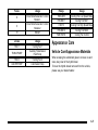
To view the hybrid screen, press the MENU button on
the radio. The hybrid screen displays when entering the
Configuration Menu.
4-13
2 NOTES
4-14
Section 5
Driving Your Vehicle
Your Driving, the Road, and the Vehicle . . . . . . . . . . 5-2
Electric Power Steering . . . . . . . . . . . . . . . . . . . . . . . . . 5-2
Towing . . . . . . . . . . . . . . . . . . . . . . . . . . . . . . . . . . . . . . . . . . . . . 5-2
Towing Your Vehicle . . . . . . . . . . . . . . . . . . . . . . . . . . . . 5-2
Towing a Trailer . . . . . . . . . . . . . . . . . . . . . . . . . . . . . . . . . 5-2
5-1
Your Driving, the Road, and the
Vehicle
Towing a Trailer
Electric Power Steering
Weight of the Trailer
This vehicle has On-Demand Electric-Assist Power
Steering instead of conventional full-time hydraulic
power steering. It uses electricity supplied by the same
battery which is re-charged by the regenerative braking
system.
How heavy can a trailer safely be?
Because the system is On-Demand Electric-Assist,
energy is used only when the steering wheel is turned,
or when the steering gear is used to help isolate the
forces of rough roads. This system does not use power
steering fluid, making it maintenance-free.
Towing
Towing Your Vehicle
Consult your dealer/retailer or a professional towing
service if the disabled vehicle needs to be towed.
5-2
For more information, see “Towing a Trailer” in the
owner manual Index.
It depends on how the rig is used. For example,
speed, altitude, road grades, outside temperature and
how much the vehicle is used to pull a trailer are all
important. It can depend on any special equipment on
the vehicle, and the amount of tongue weight the
vehicle can carry.
Maximum trailer weight is calculated assuming only the
driver is in the tow vehicle and it has all the required
trailering equipment. The weight of additional optional
equipment, passengers and cargo in the tow vehicle
must be subtracted from the maximum trailer weight.
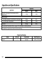
Use the following charts to determine how much the
vehicle can weigh, based upon the vehicle model and
options.
Vehicle
Axle Ratio
Maximum Trailer Weight
GCWR*
2WD 6.0 L V8
3.08
6,100 lbs (2 767 kg)
12,000 lbs (5 443 kg)
4WD 6.0 L V8
3.08
5,900 lbs (2 676 kg)
12,000 lbs (5 443 kg)
*The Gross Combination Weight Rating (GCWR) is the total allowable weight of the completely loaded vehicle and
trailer including any passengers, cargo, equipment and conversions. The GCWR for the vehicle should not be
exceeded.
Trailer Brakes
If a trailer is being towed that has trailer brakes and the
trailer brakes are manually applied while driving slower
than 25 mph (40 km/h), the vehicle may go into auto
stop mode even if the brakes are not being pressed.
Using the trailer brake system manually can make the
hybrid vehicle perform as if the brake pedal in the
vehicle is being pressed. The trailer brake operation
check will still work. If the trailer brakes are manually
applied for an extended period of time, the SERVICE
BRAKE SYSTEM DIC message comes on. The
message goes off after the trailer brakes have been
released. No other action is necessary. For more
information, see “Trailer Brakes” in the Index of the
vehicle's owner manual.
5-3
2 NOTES
5-4
Section 6
Service and Appearance Care
Service . . . . . . . . . . . . . . . . . . . . . . . . . . . . . . . . . . . . . . . . . . . . . 6-2
Doing Your Own Service Work . . . . . . . . . . . . . . . . . . 6-2
Checking Things Under the Hood . . . . . . . . . . . . . . . . . 6-3
High Voltage Devices and Wiring . . . . . . . . . . . . . . . 6-3
Engine Compartment Overview . . . . . . . . . . . . . . . . . 6-4
Automatic Transmission Fluid . . . . . . . . . . . . . . . . . . . 6-5
Drive Motor/Generator Control Module (DMCM)
Coolant Surge Tank Pressure Cap . . . . . . . . . . . . 6-8
Drive Motor/Generator Control Module (DMCM)
Cooling System . . . . . . . . . . . . . . . . . . . . . . . . . . . . . . . 6-9
Power Steering Fluid . . . . . . . . . . . . . . . . . . . . . . . . . . 6-13
Brakes . . . . . . . . . . . . . . . . . . . . . . . . . . . . . . . . . . . . . . . . .
Battery . . . . . . . . . . . . . . . . . . . . . . . . . . . . . . . . . . . . . . . . .
Jump Starting . . . . . . . . . . . . . . . . . . . . . . . . . . . . . . . . . .
Electrical System . . . . . . . . . . . . . . . . . . . . . . . . . . . . . . . . .
High Voltage Devices and Wiring . . . . . . . . . . . . . .
Fuses and Circuit Breakers . . . . . . . . . . . . . . . . . . . .
Underhood Fuse Block . . . . . . . . . . . . . . . . . . . . . . . .
Appearance Care . . . . . . . . . . . . . . . . . . . . . . . . . . . . . . . . .
Vehicle Care/Appearance Materials . . . . . . . . . . . .
Capacities and Specifications . . . . . . . . . . . . . . . . . . .
6-13
6-17
6-18
6-23
6-23
6-24
6-24
6-25
6-25
6-26
6-1
Service
{ WARNING:
Doing Your Own Service Work
{ WARNING:
Never try to do your own service on hybrid
components. You can be injured and the vehicle
can be damaged if you try to do your own service
work. Service and repair of these hybrid
components should only be performed by a
trained service technician with the proper
knowledge and tools.
6-2
You can be injured and the vehicle could be
damaged if you try to do service work on a vehicle
without knowing enough about it.
.
Be sure you have sufficient knowledge,
experience, the proper replacement parts,
and tools before attempting any vehicle
maintenance task.
.
Be sure to use the proper nuts, bolts, and
other fasteners. English and metric fasteners
can be easily confused.
If the wrong fasteners are used, parts can
later break or fall off. You could be hurt.
If doing some of your own service work, use the proper
service manual. It tells you much more about how to
service the vehicle than this manual can. To order the
proper service manual, see “Service Publications
Ordering Information” in the owner manual.
This vehicle has an airbag system. Before attempting
to do your own service work, see “Servicing Your
Airbag‐Equipped Vehicle” in the owner manual.
Keep a record with all parts receipts and list the mileage
and the date of any service work performed. See
“Maintenance Record” in the owner manual.
Checking Things Under
the Hood
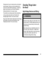
High Voltage Devices and Wiring
{ WARNING:
Exposure to high voltage can cause shock, burns,
and even death. The high voltage systems in your
vehicle can only be serviced by technicians with
special training.
High voltage devices are identified by labels. Do
not remove, open, take apart, or modify these
devices. High voltage cable or wiring has orange
covering. Do not probe, tamper with, cut,
or modify high voltage cable or wiring.
6-3
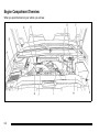
Engine Compartment Overview
When you open the hood on your vehicle, you will see:
6-4
A. See “Engine Air Cleaner/Filter” in the owner
manual.
Automatic Transmission Fluid
B. Drive Motor/Generator Control Module (DMCM).
See Drive Motor/Generator Control Module
(DMCM) Cooling System on page 6‑9.
When to Check and Change Automatic
Transmission Fluid
C. Engine Oil Dipstick. See “Engine Oil” in the owner
manual.
D. Automatic Transmission Fluid Dipstick. See
Automatic Transmission Fluid on page 6‑5.
E. Brake Fluid Reservoir. See Brakes on page 6‑13.
F. See “Underhood Fuse Block” in the owner manual.
G. See “Windshield Washer Fluid” in the owner
manual.
H. Hybrid Auxiliary Fuse Block. See Underhood Fuse
Block on page 6‑24.
I. DMCM Coolant Surge Tank Pressure Cap. See
Drive Motor/Generator Control Module (DMCM)
Coolant Surge Tank Pressure Cap on page 6‑8.
J. See “Coolant Surge Tank Pressure Cap” in the
owner manual.
K. Engine Oil Fill Cap. See “Engine Oil” in the owner
manual.
It is usually not necessary to check the transmission
fluid level. The only reason for fluid loss is a
transmission leak or overheating the transmission.
If you suspect a small leak, then use the following
checking procedures to check the fluid level. However,
if there is a large leak, then it may be necessary to have
the vehicle towed to a dealer/retailer service department
and have it repaired before driving the vehicle further.
Notice: Use of the incorrect automatic transmission
fluid may damage the vehicle, and the damages may
not be covered by the vehicle's warranty. Always
use the automatic transmission fluid listed in
Recommended Fluids and Lubricants on page 7‑2.
Change the fluid and filter at the intervals listed in the
Maintenance Schedule. See Scheduled Maintenance in
the owner manual. Be sure to use the transmission fluid
listed in Recommended Fluids and Lubricants on
page 7‑2.
6-5
How to Check Automatic Transmission
Fluid
Notice: Too much or too little fluid can damage your
transmission. Too much can mean that some of the
fluid could come out and fall on hot engine parts or
exhaust system parts, starting a fire. Too little fluid
could cause the transmission to overheat. Be sure
to get an accurate reading if you check your
transmission fluid.
Before checking the fluid level, prepare the vehicle as
follows:
1. Start the engine and park the vehicle on a level
surface. Keep the engine running.
2. Apply the parking brake and place the shift lever in
P (Park).
3. With your foot on the brake pedal, move the shift
lever through each gear range, pausing for about
three seconds in each range. Then, move the shift
lever back to P (Park).
4. Allow the engine to idle (500 – 800 RPM) for at
least one minute. Slowly release the brake pedal.
5. Keep the engine running and press the Trip/Fuel
button or trip odometer reset stem until TRANS
TEMP (Transmission Temperature) displays on the
Driver Information Center (DIC).
6-6
6. Using the TRANS TEMP reading, determine and
perform the appropriate check procedure. If the
TRANS TEMP reading is not within the required
temperature ranges, allow the vehicle to cool,
or operate the vehicle until the appropriate
transmission fluid temperature is reached.
Cold Check Procedure
Use this procedure only as a reference to determine if
the transmission has enough fluid to be operated safely
until a hot check procedure can be made. The hot
check procedure is the most accurate method to check
the fluid level. Perform the hot check procedure at the
first opportunity. Use this cold check procedure to check
fluid level when the transmission temperature is
between 24°C and 34°C (75°F and 93°F).
1. Locate the
transmission dipstick at
the rear of the engine
compartment, on the
passenger side of the
vehicle.
See Engine Compartment Overview on page 6‑4
for more information.
2. Pull out the dipstick and wipe it with a clean rag or
paper towel.
3. Install the dipstick by pushing it back in all the way,
wait three seconds, and then pull it back out again.
4. Check both sides of the dipstick and read the lower
level. Repeat the check procedure to verify the
reading.
Hot Check Procedure
Use this procedure to check the transmission fluid level
when the transmission fluid temperature is between
60°C and 75°C (140°F and 167°F).
The hot check is the most accurate method to check the
fluid level. The hot check should be performed at the
first opportunity in order to verify the cold check. The
fluid level rises as fluid temperature increases, so it is
important to ensure the transmission temperature is
within range.
1. Locate the
transmission dipstick at
the rear of the engine
compartment, on the
passenger side of the
vehicle.
5. If the fluid level is below the COLD check band,
add only enough fluid as necessary to bring the
level into the COLD band. It does not take much
fluid, generally less than 0.5 Liter (1 Pint). Do not
overfill.
6. Perform a hot check at the first opportunity after
the transmission reaches a normal operating
temperature between 60°C and 75°C (140°F
and 167°F).
7. If the fluid level is in the acceptable range, push
the dipstick back in all the way.
See Engine Compartment Overview on page 6‑4
for more information.
2. Pull out the dipstick and wipe it with a clean rag or
paper towel.
3. Install the dipstick by pushing it back in all the way,
wait three seconds, and then pull it back out again.
4. Check both sides of the dipstick and read the lower
level. Repeat the check procedure to verify the
reading.
6-7
Consistency of Readings
Always check the fluid level at least twice using
the procedure described previously. Consistency
(repeatable readings) is important to maintaining
proper fluid level. If readings are still inconsistent,
contact your dealer/retailer.
Drive Motor/Generator Control
Module (DMCM) Coolant Surge Tank
Pressure Cap
5. Safe operating level is within the HOT cross hatch
band on the dipstick. If the fluid level is not within
the HOT band, and the transmission temperature
is between 60°C and 75°C (140°F and 167°F), add
or drain fluid as necessary to bring the level into
the HOT band. If the fluid level is low, add only
enough fluid to bring the level into the HOT band.
It does not take much fluid, generally less than
0.5 Liter (1 Pint). Do not overfill.
6. If the fluid level is in the acceptable range, push
the dipstick back in all the way.
6-8
See Engine Compartment
Overview on page 6‑4
for more information on
location.
The Drive Motor/Generator Control Module (DMCM)
coolant surge tank pressure cap must be fully installed
on the hybrid coolant surge tank.
When you decide it is safe to lift the hood, here is what
you will see:
Notice: If the pressure cap is not tightly installed,
coolant loss and possible damage to the Drive
Motor/Generator Control Module (DMCM) may occur.
Be sure the cap is properly and tightly secured.
Drive Motor/Generator Control
Module (DMCM) Cooling System
In addition to the regular cooling system, the vehicle
also has a cooling system for the DMCM system. This
system is serviced differently than the vehicle's main
cooling system. The DMCM cooling system includes the
DMCM coolant surge tank, DMCM surge tank pressure
cap, DMCM cooling pumps, hybrid cooling radiator and
the Drive Motor/Generator Control Module (DMCM).
The DMCM cooling system uses a 50/50 pre-mixed
DEX-COOL™ coolant and deionized water available at
your dealer/retailer. See “Engine Coolant” and “Cooling
System” in the owner manual for more information.
A. Drive Motor/Generator
Control Module (DMCM)
D. DMCM Cooling
Hoses (Out of View)
B. Engine Coolant Surge
Tank Pressure Cap
E. DMCM Coolant
Tank Pressure Cap
C. DMCM Coolant Surge
Tank/Engine Coolant
Surge Tank
6-9
If the coolant inside the DMCM coolant surge tank is
boiling, do not do anything else until it cools down.
The coolant level should be at or above the FULL
COLD mark with the vehicle parked on a level surface.
If it is not, there might be a leak at the DMCM cooler
core, DMCM pressure cap, DMCM cooler hoses,
DMCM cooling pump or somewhere else in the DMCM
cooling system.
Notice: Running the engine when there is a leak in
the hybrid cooling system can cause the hybrid
cooling system to lose all coolant and can damage
the system. Get any leak fixed before you drive the
vehicle or run the engine.
6-10
How to Add Coolant to the DMCM
Coolant Surge Tank
If no problem has been found yet, check to see if
coolant is visible in the DMCM coolant surge tank.
If coolant is visible, add pre‐mixed DEX-COOL™
coolant, available at your dealer/retailer, at the DMCM
coolant surge tank, but be sure the DMCM cooling
system, including the DMCM coolant surge tank
pressure cap, is cool before you do it. Use the
procedure following.
{ WARNING:
Steam and scalding liquids from a hot cooling
system can blow out and burn you badly. They are
under pressure, and if you turn the coolant surge
tank pressure cap — even a little — they can come
out at high speed. Never turn the cap when the
cooling system, including the coolant surge tank
pressure cap, is hot. Wait for the cooling system
and coolant surge tank pressure cap to cool if you
ever have to turn the pressure cap.
If the DMCM coolant is empty , the vehicle must be
serviced by your dealer and a special fill procedure
must be followed.
Notice: Attempting to fill the DMCM cooling surge
tank yourself when the fluid level is empty can
damage your vehicle. Your vehicle must be
serviced.
Notice: Using coolant other than a pre‐mixed
DEX-COOL, available at your dealer/retailer, may
damage your vehicle. Any repairs would not be
covered by your warranty. Always use a pre‐mixed
DEX-COOL (silicate-free) coolant in your vehicle.
{ WARNING:
You can be burned if you spill coolant on hot
engine parts. Coolant contains ethylene glycol
and it will burn if the engine parts are hot enough.
Do not spill coolant on a hot engine.
1. Park the vehicle on a level surface and turn the
vehicle off. Remove the DMCM coolant surge tank
pressure cap when the DMCM cooling system,
including the DMCM coolant surge tank pressure
cap and DMCM cooling hoses, are no longer hot.
6-11
Turn the DMCM coolant surge tank pressure cap
slowly counterclockwise (left) about one full turn.
Wait 30 seconds.
5. Add the pre‐mixed DEX‐COOL™, available at your
dealer/retailer, until the coolant level is maintained
at the FULL COLD mark. This should take no
longer than two minutes of hybrid cooling pump
operation.
If the level cannot be kept at the FULL COLD level,
your vehicle may need service. See your dealer/
retailer.
6. Then replace the
DMCM coolant surge
tank pressure cap. Be
sure the pressure cap
is hand-tight and fully
seated.
2. Then keep turning the DMCM coolant surge tank
pressure cap slowly, and remove it.
3. Add the pre‐mixed DEX‐COOL™, available at your
dealer/retailer, to the DMCM coolant surge tank
until the level reaches the FULL COLD mark.
4. Turn the ignition to ON/RUN without starting the
engine. The hybrid cooling pumps will run and any
trapped air will purge to the surge tank.
6-12
Notice: Using tap water, cooling system sealers or
conditioners in an attempt to stop coolant leaks can
damage the DMCM and engine cooling systems.
Never use tap water, cooling system sealers or
conditioners in your cooling system.
Power Steering Fluid
The vehicle has electric power steering and does not
use power steering fluid.
There are only two reasons why the brake fluid level in
the reservoir might go down:
.
The brake fluid level goes down because of normal
brake lining wear. When new linings are installed,
the fluid level goes back up.
.
A fluid leak in the brake hydraulic system can also
cause a low fluid level. Have the brake hydraulic
system fixed, since a leak means that sooner or
later the brakes will not work well.
Brakes
Brake Fluid
The brake master cylinder
reservoir is filled with
DOT 3 brake fluid. See
Engine Compartment
Overview on page 6‑4
for the location of the
reservoir.
6-13
Do not top off the brake fluid. Adding fluid does not
correct a leak. If fluid is added when the linings are
worn, there will be too much fluid when new brake
linings are installed. Add or remove brake fluid, as
necessary, only when work is done on the brake
hydraulic system.
Checking Brake Fluid
Check brake fluid by looking at the brake fluid reservoir.
See Engine Compartment Overview on page 6‑4.
{ WARNING:
If too much brake fluid is added, it can spill on the
engine and burn, if the engine is hot enough. You
or others could be burned, and the vehicle could
be damaged. Add brake fluid only when work is
done on the brake hydraulic system. See
“Checking Brake Fluid” in this section.
When the brake fluid falls to a low level, the brake
warning light comes on. See “Brake System Warning
Light” in the owner manual.
Refer to the Maintenance Schedule to determine when
to check the brake fluid. See “Scheduled Maintenance”
in the owner manual.
With the engine not running for at least one minute, the
maximum fluid level (A) is at the top of the reservoir
body. With the engine running, the fluid level should be
in the proper operating range (B) between the MIN and
MAX marks. If it is not, have the brake hydraulic system
checked to see if there is a leak.
After work is done on the brake hydraulic system, make
sure the level, with the engine running, is in the proper
operating range (B) between the MIN and MAX marks.
6-14
What to Add
Use only new DOT 3 brake fluid from a sealed
container. See “Recommended Fluids and Lubricants”
in the owner manual.
Notice:
.
Using the wrong fluid can badly damage
brake hydraulic system parts. For example,
just a few drops of mineral-based oil, such
as engine oil, in the brake hydraulic system
can damage brake hydraulic system parts so
badly that they will have to be replaced. Do
not let someone put in the wrong kind of
fluid.
.
If brake fluid is spilled on the vehicle's
painted surfaces, the paint finish can be
damaged. Be careful not to spill brake
fluid on the vehicle. If you do, wash it off
immediately. See “Washing Your Vehicle”
in the owner manual.
Always clean the brake fluid reservoir cap and the area
around the cap before removing it. This helps keep dirt
from entering the reservoir.
{ WARNING:
With the wrong kind of fluid in the brake hydraulic
system, the brakes might not work well. This could
cause a crash. Always use the proper brake fluid.
6-15
Brake Wear
This vehicle has disc brakes. Disc brake pads have
built-in wear indicators that make a high-pitched
warning sound when the brake pads are worn and new
pads are needed. The sound can come and go or be
heard all the time the vehicle is moving, except when
applying the brake pedal firmly.
{ WARNING:
The brake wear warning sound means that soon
the brakes will not work well. That could lead to
an accident. When the brake wear warning sound
is heard, have the vehicle serviced.
Notice: Continuing to drive with worn-out brake
pads could result in costly brake repair.
Some driving conditions or climates can cause a brake
squeal when the brakes are first applied or lightly
applied. This does not mean something is wrong with
the brakes.
Properly torqued wheel nuts are necessary to help
prevent brake pulsation. When tires are rotated, inspect
brake pads for wear and evenly tighten wheel nuts in
the proper sequence to torque specifications in
“Capacities and Specifications” in the owner manual.
Brake linings should always be replaced as complete
axle sets.
Brake Pedal Travel
See your dealer/retailer if the brake pedal does not
return to normal height, or if there is a rapid increase in
pedal travel. This could be a sign that brake service
might be required.
Brake Adjustment
Every time the brakes are applied, the disc brakes
adjust for wear.
6-16
Replacing Brake System Parts
The braking system on a vehicle is complex. Its many
parts have to be of top quality and work well together if
the vehicle is to have really good braking. The vehicle
was designed and tested with top-quality brake parts.
When parts of the braking system are replaced — for
example, when the brake linings wear down and new
ones are installed — be sure to get new approved
replacement parts. If this is not done, the brakes might
not work properly. For example, if someone puts in
brake linings that are wrong for the vehicle, the balance
between the front and rear brakes can change — for the
worse. The braking performance expected can change
in many other ways if the wrong replacement brake
parts are installed.
Battery
This vehicle has a standard 12‐volt battery and a
high‐voltage hybrid battery.
Refer to the replacement number on the original battery
label when a new standard 12‐volt battery is needed.
Only a trained service technician with the proper
knowledge and tools should inspect, test, or replace
the hybrid battery. See your dealer/retailer if the hybrid
battery needs service. The dealer/retailer has
information on how to recycle the hybrid battery.
There is also information available at
http://www.recyclemybattery.com.
If an airbag inflates or the vehicle has been in a crash,
the vehicle's sensing system might command the
automatic hybrid battery disconnect to open. See
Replacing Restraint System Parts After a Crash on
page 2‑2 for more information .
{ DANGER:
Battery posts, terminals, and related accessories
contain lead and lead compounds, chemicals
known to the State of California to cause cancer
and reproductive harm. Wash hands after
handling.
6-17
Vehicle Storage
Jump Starting
{ WARNING:
{ WARNING:
Batteries have acid that can burn you and gas
that can explode. You can be badly hurt if you are
not careful. See Jump Starting on page 6‑18 for
tips on working around a battery without
getting hurt.
Personal injury, death, or damage to the vehicle
can result if you try jump starting or using a
battery charger on the high voltage hybrid battery.
Use only the 12-volt battery for jump starting and
charging.
Infrequent Usage: Remove the 12‐volt battery black,
negative (−) cable from the battery to keep the battery
from running down.
Extended Storage: Remove the 12‐volt battery black,
negative (−) cable from the battery or use a battery
trickle charger.
Remember to reconnect the battery when ready to drive
the vehicle.
If the vehicle's 12‐volt battery has run down, you may
want to use another vehicle and some jumper cables to
start your vehicle. Use the following steps to do it safely.
{ WARNING:
Batteries can hurt you. They can be dangerous
because:
.
They contain acid that can burn you.
.
They contain gas that can explode or ignite.
.
They contain enough electricity to burn you.
If you do not follow these steps exactly, some or
all of these things can hurt you.
6-18
Notice: Ignoring these steps could result in costly
damage to the vehicle that would not be covered by
the warranty.
Trying to start the vehicle by pushing or pulling it
will not work, and it could damage the vehicle.
1. Check the other vehicle. It must have a 12‐volt
battery with a negative ground system.
Notice: If the other vehicle's system is not a 12-volt
system with a negative ground, both vehicles can
be damaged. Only use vehicles with 12-volt systems
with negative grounds to jump start your vehicle.
2. Get the vehicles close enough so the jumper
cables can reach, but be sure the vehicles are not
touching each other. It could cause a ground
connection you do not want. You would not be able
to start your vehicle, and the bad grounding could
damage the electrical systems.
To avoid the possibility of the vehicles rolling, set
the parking brake firmly on both vehicles involved
in the jump start procedure. Put the automatic
transmission in P (Park) or a manual transmission
in N (Neutral) before setting the parking brake.
If you have a four-wheel-drive vehicle, be sure the
transfer case is in a drive gear, not in N (Neutral).
Notice: If you leave the radio or other accessories
on during the jump starting procedure, they could
be damaged. The repairs would not be covered by
the warranty. Always turn off the radio and other
accessories when jump starting the vehicle.
3. Turn off the ignition on both vehicles. Unplug
unnecessary accessories plugged into the
cigarette lighter or the accessory power outlets.
Turn off the radio and all the lamps that are not
needed.
This avoids sparks and helps save both batteries.
It could save the radio!
4. Open the hood on the other vehicle and locate the
positive (+) and negative (−) terminal locations on
that vehicle.
6-19
{ WARNING:
An electric fan can start up even when the engine
is not running and can injure you. Keep hands,
clothing and tools away from any underhood
electric fan.
{ WARNING:
The positive (+) connection is located under a red
plastic cover at the positive battery post. To
uncover the remote positive (+) terminal, open the
red plastic cover.
5. The remote negative (−) is a solid engine ground.
Using an open flame near a battery can cause
battery gas to explode. People have been hurt
doing this, and some have been blinded. Use a
flashlight if you need more light.
Be sure the battery has enough water. You do not
need to add water to the battery installed in your
new vehicle. But if a battery has filler caps, be
sure the right amount of fluid is there. If it is low,
add water to take care of that first. If you do not,
explosive gas could be present.
Battery fluid contains acid that can burn you. Do
not get it on you. If you accidentally get it in your
eyes or on your skin, flush the place with water
and get medical help immediately.
6-20
{ WARNING:
7. Connect the red positive (+) cable to the
positive (+) terminal of the vehicle with the dead
battery. Use a remote positive (+) if the vehicle
has one.
Fans or other moving engine parts can injure you
badly. Keep your hands away from moving parts
once the engine is running.
8. Do not let the other end touch metal. Connect it to
the positive (+) terminal of the good battery. Use a
remote positive (+) if the vehicle has one.
6. Check that the jumper cables do not have loose or
missing insulation. If they do, you could get a
shock. The vehicles could be damaged too.
Before you connect the cables, here are some
basic things you should know. Positive (+) goes to
positive (+) or to a remote positive (+) terminal if
the vehicle has one. Negative (−) will go to a
heavy, unpainted metal engine part or a solid
engine ground.
9. Now connect the black negative (−) cable to the
negative (−) terminal of the good battery. Use a
remote negative (−) if the vehicle has one.
Do not let the other end touch anything until the
next step. The other end of the negative (−) cable
does not go to the dead battery. It goes to a heavy,
unpainted metal engine part or to the remote
negative (−) terminal on the vehicle with the dead
battery.
Do not connect positive (+) to negative (−) or you
will get a short that would damage the battery and
maybe other parts too. Do not connect the
negative (−) cable to the negative (−) terminal on
the dead battery because this can cause sparks.
6-21
10. Connect the other end of the negative (−) cable to
the remote negative (−) terminal, on the vehicle
with the dead battery.
Jumper Cable Removal
11. Now start the vehicle with the good battery and run
the engine for a while.
12. Try to start the vehicle that had the dead battery.
If it will not start after a few tries, it probably needs
service.
Notice: If the jumper cables are connected or
removed in the wrong order, electrical shorting may
occur and damage the vehicle. The repairs would
not be covered by the vehicle warranty. Always
connect and remove the jumper cables in the
correct order, making sure that the cables do not
touch each other or other metal.
A. Heavy, Unpainted Metal Engine Part or Remote
Negative (−) Terminal
B. Good Battery or Remote Positive (+) and Remote
Negative (−) Terminals
C. Dead Battery or Remote Positive (+) Terminal
6-22
To disconnect the jumper cables from both vehicles:
1. Disconnect the black negative (−) cable from the
vehicle that had the bad battery.
2. Disconnect the black negative (−) cable from the
vehicle with the good battery.
3. Disconnect the red positive (+) cable from the
vehicle with the good battery.
4. Disconnect the red positive (+) cable from the other
vehicle.
5. Return the remote positive (+) terminal cover to its
original position.
Electrical System
High Voltage Devices and Wiring
{ WARNING:
Exposure to high voltage can cause shock, burns,
and even death. The high voltage systems in your
vehicle can only be serviced by technicians with
special training.
High voltage devices are identified by labels. Do
not remove, open, take apart, or modify these
devices. High voltage cable or wiring has orange
covering. Do not probe, tamper with, cut,
or modify high voltage cable or wiring.
6-23
Fuses and Circuit Breakers
The wiring circuits in the vehicle are protected from
short circuits by a combination of fuses, circuit breakers
and fusible thermal links. This greatly reduces the
chance of fires caused by electrical problems.
information on its location. For more information on the
main underhood fuse block, see “Underhood Fuse
Block” in the owner manual.
Be sure you replace a bad fuse with a new one of the
identical size and rating.
If you ever have a problem on the road and do not have
a spare fuse, you can borrow one that has the
same amperage. Just pick some feature of the vehicle
that you can get along without, like the radio or cigarette
lighter, and use its fuse, if it is the correct amperage.
Replace it as soon as you can.
The vehicle also has a special fuse in the battery box
for the 300-volt batteries. If this fuse has failed and
needs to be replaced, the vehicle will be disabled and
you will need to have the vehicle repaired by your
dealer/retailer. Do not attempt to self-service this fuse.
Underhood Fuse Block
Hybrid Auxiliary Underhood Fuse Block
The hybrid underhood fuse block is located in the
engine compartment near the front of the vehicle. Lift
the cover for access to the fuse/relay block. See Engine
Compartment Overview on page 6‑4 for more
6-24
Fuses
1
2
3
4
5
6
7
Usage
ACPO (SUV Only)
BECM FAN
ACCM
CAB HTR PMP
EMPTY
COOL PUMP
EPS
Fuses
8
9
10
J‐Case
FAN 1
TRANS PUMP
FAN 2
CAB HTR PMP
Usage
Drive Motor/Generator Control
Module 1
Drive Motor/Generator Control
Module 2
BECM
Usage
Cooling Fan 1
Auxiliary Transmission
Fluid Pump
Cooling Fan 2
Cab Heater Pump
Relays
FAN LOW
FAN MID 1
FAN HI
FAN MID 2
FAN CNTRL
Usage
Cooling Fan Low Speed Relay
Cooling Fan Mid 1
Cooling Fan High Speed Relay
Cooling Fan Mid 2
Cooling Fan Control
Appearance Care
Vehicle Care/Appearance Materials
When scraping the windshield glass to remove ice and
snow, stay clear of the hybrid decal.
To have the hybrid decals removed from the vehicle,
please see your dealer/retailer.
6-25
Capacities and Specifications
Capacities
Application
Automatic Transmission* (Pan Removal and Filter
Replacement)
English
Metric
11.5 qt
10.9 L
Cooling System
Drive Motor Generator Control Module Cooling System
2.9 qt
2.7 L
6.0L V8 Engine Cooling System
17.2 qt
16.3 L
26.0 gal
98.4 L
Fuel Tank
*See Automatic Transmission Fluid o n p a g e 6 ‑ 5 for information on checking fluid level.
All capacities are approximate. Recheck fluid level after filling.
Engine Specifications
Engine
6.0L V8
6-26
VIN Code
J
Transmission
Automatic
Spark Plug Gap
0.040 in (1.02 mm)
Section 7
Maintenance Schedule
Maintenance Schedule . . . . . . . . . . . . . . . . . . . . . . . . . . . . 7-2
Recommended Fluids and Lubricants . . . . . . . . . . . 7-2
Engine Drive Belt Routing . . . . . . . . . . . . . . . . . . . . . . . 7-2
7-1
Maintenance Schedule
Recommended Fluids and
Lubricants
Fluids identified below are specific to the hybrid vehicle
and can be obtained from your dealer/retailer. See the
owner manual for the other fluids and lubricants
recommended for the vehicle.
Usage
Fluid/Lubricant
Always use the pre-mixed
Drive Motor/
50/50 mixture of de‐ionized water and
Generator
DEX-COOL® (silicate-free) coolant
Control Module available at your dealer/retailer. See
(DMCM) Cooling Drive Motor/Generator Control Module
System
(DMCM) Cooling System o n
page 6‑9.
7-2
Engine Drive Belt Routing
A
D
Antilock Brake System (ABS)
Warning Light . . . . . . . . . . . . . . . . . . . . . . . . . . . . . . . . . . . . . . 4-7
Audio System(s)
Navigation/Radio System . . . . . . . . . . . . . . . . . . . . . . . . . 4-13
Automatic Transmission, Fluid . . . . . . . . . . . . . . . . . . . . . . .6-5
Drive Motor/Generator Control Module (DMCM)
Coolant Surge Tank Pressure Cap . . . . . . . . . . . . . . . . .6-8
Drive Motor/Generator Control Module (DMCM)
Cooling System . . . . . . . . . . . . . . . . . . . . . . . . . . . . . . . . . . . .6-9
Driver Information Center (DIC) . . . . . . . . . . . . . . . . . . . . 4-11
Warnings and Messages . . . . . . . . . . . . . . . . . . . . . . . . . 4-11
B
Battery . . . . . . . . . . . . . . . . . . . . . . . . . . . . . . . . . . . . . . . . . . . . 6-17
Belt Routing, Engine . . . . . . . . . . . . . . . . . . . . . . . . . . . . . . . . .7-2
Brakes . . . . . . . . . . . . . . . . . . . . . . . . . . . . . . . . . . . . . . . . . . . . . 6-13
Regenerative Braking . . . . . . . . . . . . . . . . . . . . . . . . . . . . . 3-21
System Warning Light . . . . . . . . . . . . . . . . . . . . . . . . . . . . . 4-5
C
Canadian Owners . . . . . . . . . . . . . . . . . . . . . . . . . . . . . . . . . . . . . ii
Capacities and Specifications . . . . . . . . . . . . . . . . . . . . . . 6-26
Charging System Light . . . . . . . . . . . . . . . . . . . . . . . . . . . . . .4-4
Climate Controls . . . . . . . . . . . . . . . . . . . . . . . . . . . . . . . . . . . . .4-2
Coolant
Engine Temperature Gage . . . . . . . . . . . . . . . . . . . . . . . . . 4-8
Coolant Surge Tank Pressure Cap, (DMCM) . . . . . . . . .6-8
Cooling System, (DMCM) . . . . . . . . . . . . . . . . . . . . . . . . . . . .6-9
Covers
Tonneau . . . . . . . . . . . . . . . . . . . . . . . . . . . . . . . . . . . . . . 3-2, 3-7
E
Engine
Compartment Overview . . . . . . . . . . . . . . . . . . . . . . . . . . . . 6-4
Coolant Temperature Gage . . . . . . . . . . . . . . . . . . . . . . . . 4-8
Drive Belt Routing . . . . . . . . . . . . . . . . . . . . . . . . . . . . . . . . . 7-2
Engine Coolant Heater . . . . . . . . . . . . . . . . . . . . . . . . . . . . 3-19
F
Fluid
Power Steering . . . . . . . . . . . . . . . . . . . . . . . . . . . . . . . . . . . 6-13
Fuel
Gage . . . . . . . . . . . . . . . . . . . . . . . . . . . . . . . . . . . . . . . . . . . . . 4-10
Fuel Economy Gage . . . . . . . . . . . . . . . . . . . . . . . . . . . . . . . . .4-5
i-1
G
J
Gages
Engine Coolant Temperature . . . . . . . . . . . . . . . . . . . . . . 4-8
Fuel . . . . . . . . . . . . . . . . . . . . . . . . . . . . . . . . . . . . . . . . . . . . . . 4-10
Fuel Economy . . . . . . . . . . . . . . . . . . . . . . . . . . . . . . . . . . . . . 4-5
Oil Pressure . . . . . . . . . . . . . . . . . . . . . . . . . . . . . . . . . . . . . . . 4-8
Tachometer . . . . . . . . . . . . . . . . . . . . . . . . . . . . . . . . . . . . . . . . 4-4
Jump Starting . . . . . . . . . . . . . . . . . . . . . . . . . . . . . . . . . . . . . . 6-18
H
High Voltage Devices and Wiring . . . . . . . . . . . . . . . . . . . .6-3
L
Lights
Antilock Brake System (ABS) Warning . . . . . . . . . . . . . 4-7
Brake System Warning . . . . . . . . . . . . . . . . . . . . . . . . . . . . 4-5
Charging System . . . . . . . . . . . . . . . . . . . . . . . . . . . . . . . . . . 4-4
Oil Pressure . . . . . . . . . . . . . . . . . . . . . . . . . . . . . . . . . . . . . . . 4-9
StabiliTrak® Indicator . . . . . . . . . . . . . . . . . . . . . . . . . . . . . . 4-7
I
M
Instrument Panel Cluster . . . . . . . . . . . . . . . . . . . . . . . . . . . .4-3
Introduction . . . . . . . . . . . . . . . . . . . . . . . . . . . . . . . . . . . . . . . . . . . iii
Maintenance Schedule
Recommended Fluids and Lubricants . . . . . . . . . . . . . 7-2
Manual, How to Use . . . . . . . . . . . . . . . . . . . . . . . . . . . . . . . . . . iii
i-2
N
Navigation/Radio System . . . . . . . . . . . . . . . . . . . . . . . . . . 4-13
O
Oil
Pressure Light . . . . . . . . . . . . . . . . . . . . . . . . . . . . . . . . . . . . . 4-9
Oil Pressure Gage . . . . . . . . . . . . . . . . . . . . . . . . . . . . . . . . . . .4-8
Owners, Canadian . . . . . . . . . . . . . . . . . . . . . . . . . . . . . . . . . . . . . ii
P
Power
Steering Fluid . . . . . . . . . . . . . . . . . . . . . . . . . . . . . . . . . . . . . 6-13
R
Radios
Navigation/Radio System . . . . . . . . . . . . . . . . . . . . . . . . . 4-13
Rear Seat Operation . . . . . . . . . . . . . . . . . . . . . . . . . . . . . . . . .2-2
Recommended Fluids and Lubricants . . . . . . . . . . . . . . .7-2
Regenerative Braking . . . . . . . . . . . . . . . . . . . . . . . . . . . . . . 3-21
Restraint System Check
Replacing Restraint System Parts
After a Crash . . . . . . . . . . . . . . . . . . . . . . . . . . . . . . . . . . . . 2-2
Running the Vehicle While Parked . . . . . . . . . . . . . . . . . 3-21
S
Seats
Rear Seat Operation . . . . . . . . . . . . . . . . . . . . . . . . . . . . . . . 2-2
Service
Doing Your Own Work . . . . . . . . . . . . . . . . . . . . . . . . . . . . . 6-2
Specifications and Capacities . . . . . . . . . . . . . . . . . . . . . . 6-26
StabiliTrak® Indicator Light . . . . . . . . . . . . . . . . . . . . . . . . . .4-7
Starting Your Vehicle . . . . . . . . . . . . . . . . . . . . . . . . . . . . . . 3-14
Steering
Fluid, Power . . . . . . . . . . . . . . . . . . . . . . . . . . . . . . . . . . . . . . 6-13
i-3
T
V
Tachometer . . . . . . . . . . . . . . . . . . . . . . . . . . . . . . . . . . . . . . . . . .4-4
Tonneau Cover . . . . . . . . . . . . . . . . . . . . . . . . . . . . . . . . . 3-2, 3-7
Towing
Towing Your Vehicle . . . . . . . . . . . . . . . . . . . . . . . . . . . . . . . 5-2
Trailer . . . . . . . . . . . . . . . . . . . . . . . . . . . . . . . . . . . . . . . . . . . . . 5-2
Transmission, Automatic Fluid . . . . . . . . . . . . . . . . . . . . . . .6-5
Vehicle
Running While Parked . . . . . . . . . . . . . . . . . . . . . . . . . . . . 3-21
Voltage Devices, and Wiring . . . . . . . . . . . . . . . . . . . . . . . . .6-3
i-4
W
Wiring, High Voltage Devices . . . . . . . . . . . . . . . . . . . . . . . .6-3