1
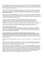
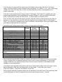
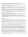
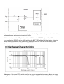
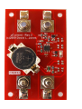
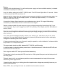
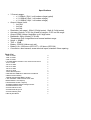
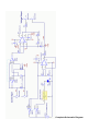
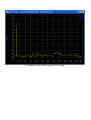
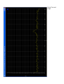
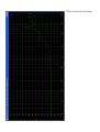
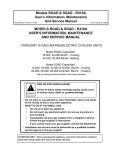
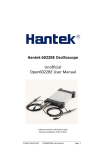
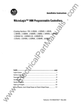
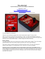
The µCurrent
A professional precision current adapter for Multimeters
By David L. Jones
([email protected])
www.alternatezone.com/electronics/ucurrent
www.eevblog.com
(Copyright© 2010 David L. Jones – Freely distributable in the original unaltered PDF format ONLY)
A current adapter for multimeters?
“But don’t most multimeters already have current measurement ranges?” I hear you ask.
Well, yes, they do of course. But most multimeters, be they a no-name $10 hardware store throwaway model, or a $1000 highly accurate brand name meter, all suffer from two rather annoying issues
with their current measurement ranges - burden voltage and reduced accuracy.
Burden Voltage
The biggest problem with current measurement ranges is called “burden voltage”. This is the voltage
that the internal current shunt resistor drops as you pass your circuit current through it.
The burden voltage is typically specified in millivolts per Amps (mV/A). The value will change for
different current ranges, so you might have 1mV/A, 1mV/mA, or 1mV/µA for example.
Normally you may not give burden voltage a second thought, as like many, you probably think it’s
fairly insignificant in most applications. In fact, most people would be hard pressed to tell you what the
burden voltage of their particular multimeter actually is. It’s usually buried away in the user manual, if
it’s mentioned at all. Next time you borrow a colleague’s meter, ask them what the burden voltage is,
and watch their reaction…
At small displayed currents the burden voltage is usually not an issue, but at larger displayed currents
(relative to Full-Scale) the burden voltage can be very high, even in the order of several volts! This
can often force you to use a higher current range (with a lower current shut resistor), with subsequent
loss of resolution and (often) accuracy.
You may have encountered this many times before as your circuit either not working or “playing up”
on too low a current range – that’s the burden voltage at work, starving your circuit of the voltage it
needs to function correctly. You usually have no option but to reluctantly switch to a higher current
range to lessen the effect.
The problem can also be highlighted with the many 4 ½ digit or “10000 count” meters on the market.
In theory they allow you to get an extra digit of resolution over a 3½ digit meter. But you may now find
yourself trying to measure for example 990.0µA on the 1mA range with a burden voltage of just under
1V. Can your circuit really handle a 1V drop?
The burden voltage of a multimeter is determined primarily by the shunt resistor used for
measurement, but on the higher current ranges (mA & A) it also includes the protection fuse
resistance, and to a much lesser extent, any switch and test lead contact resistance. Some
manufacturers will specify it as a total, or just the shunt resistor, or in many cases not mention it at all!
Some meters will specify it as a maximum voltage drop only. For example, “300mV max”. In this
case, to get the mV/A value you simply divide that voltage by the full-scale range current.
Low Voltage Current Measurement
The recent trend toward low voltage microcontrollers and other silicon devices (some operating as
low as 1V or less!) have really highlighted the need for consideration of the burden voltage when
measuring the chip current from its supply rail. 3.3V supplies have been entrenched everywhere for a
long time now, and the trend is going lower.
A common task these days is to measure the accurate sleep and operating current of a
microcontroller for instance. Indeed, with the lower the supply voltage of today’s battery powered
circuits, the greater the requirement to more accurately measure the supply current. So the industry
has changed, but meters haven’t really kept up with the pace when it comes to accurate current
measurement. You think they may have as meters are getter more “accurate” for less cost, but that’s
only part of the story.
Let’s look at how the supply voltage can impact your current measurement, or vice-versa as the case
may be:
Lets say you want to measure the supply current of a chip or circuit taking 200mA using say a 4000
count meter on the 400mA range. A not uncommon scenario, and one you would think would be
pretty easy for any mutlimeter to handle right? – Hold on…
A typical high end “accurate” multimeter will have a “low” 1mV/mA burden voltage (about as low as it
gets), so this means the meter will drop 200mV across its shunt resistor at 200mA. This represents
an almost tolerable 4% (200mV / 5V * 100) of a 5V supply voltage. This may not be a big deal if your
supply voltage is spot on 5V, as your chip will get 4.8V and still be within spec. But what if it’s already
say 4.8V?, your chip or circuit is now getting 4.6V and may be outside of its operational spec. This
already shows the limitation of the current range on a typically mid to high end multimeter. Not to
even mention the circuit current can differ when you lower the rail by 0.2V…
Let’s now say you need to do the same thing on a modern circuit or chip with say a 1.2V power
supply. That same 200mV burden voltage is now a whopping 17% (200mV / 1.2V * 100) of the supply
voltage. Your circuit will likely fail to function correctly and this is clearly not acceptable, not to
mention inaccurate.
Think this is only a problem with “cheap” meters? Think again. The Fluke 87-V, probably the most
popular high-performance meter available has a burden voltage of 1.8mV/mA (which is still pretty
good). So the above numbers are even worse – a 360mV drop for a 200mA current.
Sure, you can switch up a current range, using the 10A jack, with its burden voltage of say 10mV/A,
giving you a very nice drop of only 2mV. But your display is now showing 0.200 or 0.20 instead of
200.0 – you’ve just lost a valuable digit or two of resolution. And the higher 10A current range is likely
much less accurate than the mA range too!
Let’s have a look at the quoted burden voltage of some typical multimeters:
Burden
Burden
Multimeter Model
Approx
Cost($)
Voltage
Voltage
(mA range)
(µA range)
Meterman 5XP (3.5 digit)
$65
1V max
300mV max
JayTech QM-1340 (4.5 digit)
$99
5mV/mA
0.11mV / µA
Meterman 30XR
$120
4.6mV / Ma
1mV / µA
Protek 506
$175
1mV / mA
1mV / µA
Meterman 37XR (10,000 count)
$250
10mV / mA
1mV / µA
B&K 390A (4000 count)
$380
2V max
500mV max
Fluke 77 series III (3.5 digit)
$400
6 mV / mA
N/A
Fluke 77 series IV (6000 count)
$425
2mV / mA
N/A
Fluke 79 series III (3.5 digit)
$375
11mV / mA
N/A
Fluke 177/179 series IV (6000 count)
$430
2mV / mA
N/A
Fluke 27
$900
5.6mV / mA
0.5mV / µA
Fluke 80 series V (4.5 digit)
$720
1.8mV / mA
0.1mV / µA
Agilent U1251A (4.5 digit)
$680
1mV / mA
0.1mV / µA
Extech MM570 (500,000 count)
$680
3.3mV / mA
0.15mV / µA
Fluke 289 (50,000 count)
$950
1.8mV / mA
0.1mV / µA
Gossen MetraHit E-XTRA (60,000
$1700
300mV max
150mV max
count)
Fluke 8808A (5.5 digit)
$1100
1mV / mA
1mV max
Fluke 8846A (6.5 digit)
$2100
500mV max
15mV max
Keithley 197A Microvolt (5.5 digit)
N/A
300mV max
300mV max
As you can see from the table, things can improve a bit with the more expensive meters, particularly
on the µA ranges. But an expensive precision meter is by no means a guarantee of a low burden
voltage. Even many very expensive top-of-the-line bench meters can have unacceptable burden
voltages for many applications.
It should be noted that whilst some meters will have a fixed burden voltage for all mA ranges, others
like the Meterman 30XR have individual specs for each range – in this case: 2mA range =
100mV/mA, 20mA = 13mV/mA, and 200mA = 4.6mV/mA
Some popular and highly regarded meters like the Meterman 37XR and Fluke 79 are particularly bad
on their mA range, an order of magnitude worse than some cheaper meters – beware.
Take the above example again, the Meterman 37XR would drop a whopping 2V (10mV*200) on its
mA range for 200mA. Not much good when your supply voltage is only 3.3V, or 5V, or even 12V.
And the 37XR is a relatively expensive 10000 count meter that is supposed to be capable of
measuring 999.9mA on its 1A range – which it will try to do. But that would be a gigantic 10V drop
which the meter itself cannot even handle, so it’s limited to a nominal 400mA with a 4V drop on that
range. Crazy huh?
I’m sure by now you are getting the idea that burden voltage can be a real hidden problem lurking in
your meter. What is your meter rated at?
Accuracy
And the second problem mentioned? That would be one of accuracy. Most multimeters will have a
much wider accuracy specification for current than they will for the DC voltage ranges, or the “Basic
DC accuracy” as it’s called.
The Meterman 37XR for example is quite an accurate meter at 0.1%(+5 counts) on DC volts, and is
sold and marketed as such. But its current accuracy?, a not so impressive 0.5%(+10 counts) on DC
current, jumping to 1.5% for the 10A range.
An even better example is the Fluke 27, with 0.1%(+1 counts) DC volts accuracy and 0.75%(+2
counts) mA/uA DC current accuracy.
Most other meters are very similar, with a factor of 5 or more between the DC volts and DC current
accuracy being quite typical.
This issue is more prevalent with DC than AC, but can also apply to the AC voltage vs AC current
ranges as well. Some meters can actually have very poor AC current accuracy and/or reduced AC
frequency response compared to their AC millivolt range. Take the Fluke 27 again as an example.
The ACV accuracy is 0.5%+3 to 2KHz, but the AC current ranges are only 1.5%+2 to 1KHz.
The Solution
You guessed it, the project to be presented here presents a neat solution to these issues. The
µCurrent (pronounced “micro current”) is a simple yet accurate professional grade precision amplified
current adapter for multimeters. It provides in many cases up to a 100 fold reduction in burden
voltage for a given current range!
An additional feature is a nA current range not found on most multimeters at any price. This gives any
cheap 3.5 digit multimeter the ability to resolve 0.1nA (100pA), and 0.01nA (10pA) on a 4.5 digit
multimeter. All with an excellent accuracy of <0.2%.
The µCurrent is in many cases also able to improve upon your meters current range accuracy by
using your meters more accurate mVDC or mVAC voltage ranges instead to display the DC or AC
current. With AC the frequency response extends flat up to 10KHz, but THD increases substantially
above 2KHz. Still a very respectable AC response range, surpassing that of many meters on current
and voltage ranges.
Typical accuracy of the µCurrent itself is better than 0.2% on the µA and nA ranges, and 0.5% or
better on the mA range. Unfortunately it is not easy to obtain a 0.1% precision shunt resistor for the
mA range, as the 10 milliohm value is too low.
The burden voltage of the µCurrent is a fixed 10µV/µA and 10µV/nA on the lower ranges, and varies
on the mA range due to the switch resistance, but 70µV/mA is a nominal upper figure. These figures
are unmatched by almost any meter on the market.
So for example at a full scale of say 1000µA, that’s a maximum burden voltage of only 10mV. So
measuring the current rail of a 1.2V logic supply with full scale resolution would give you a worst case
drop of around 0.8%, a fairly insignificant figure.
The output voltage in mV is directly proportional to the input current, so you can simply read the
current value from your multimeter’s mV DC range.
The µCurrent thus effectively eliminates any issues to do with burden voltage by making it
insignificant in all but the most extreme applications.
How It Works
A current adapter is basically just a shunt resistor with an amplifier, and that is essentially all the
µCurrent is. But there are a few extra neat features to the design to make it as professional and
handy as possible, as we’ll see.
The heart of the design is U1, a Maxim MAX4239, a special “ultra-low offset/drift, low noise precision
amplifier”. Whew, what a mouthful!
As the name suggests, it’s a pretty high spec device. The key figure in this application is the nearzero offset voltage. And not just “low offset” like many precision op-amps, this one has almost no
practical offset voltage at all. 0.1uV typical, with a maximum figure of 2.5uV over the entire
temperature range, if you want to know the actual numbers.
This class of op-amps are known as “auto-zero” (or “chopper”) amplifiers.
Maxim are a bit hush-hush on the actual internal workings of their particular device, saying only
“These characteristics are achieved through a patented autozeroing technique that samples and
cancels the input offset and noise of the amplifier. The pseudorandom clock frequency varies from
10kHz to 15kHz, reducing intermodulation distortion present in chopper-stabilized amplifiers.”
But we can get a good idea of how a basic auto-zero amplifier woks in the following diagram.
An auto-zero amplifier is basically the combination of a normal op-amp (Ab), with a “nulling” op-amp
(Aa) that continually corrects for the DC offset voltage of the main amplifier.
So the device is driven by a clock (internal) that drives a two phase offset process.
In the first phase (figure a), the main amplifier (AB) is offset with the voltage stored on capacitor CM2.
The nulling amplifier (AA) measures its own offset voltage and stores it on capacitor CM1.
In the second phase (figure b), the nulling amplifier (AA) measures the input difference voltage on AB
and stores this value on capacitor CM2, ready for the next cycle.
Using this process the offset voltage of the main amplifier is continually eliminated.
A side benefit of this is that it also eliminates typical op-amp 1/f noise, as the low frequency is treated
as a slowly varying input offset voltage and hence gets cancelled out.
The pseudo-random clock used in the MAX4239 also helps to reduce the effects of intermodulation
distortion as AC signals approach half the chopping frequency (10-15KHz).
This remarkable DC performance allows the µCurrent to have insignificant output offset errors, and
will display zero volts output for a zero current input.
It is also quite low power, around 600uA, thus allowing for battery operation from a small lithium
battery. The supply voltage is specified down to 2.7V, making it ideal for operation from a single 3V
lithium battery.
The MAX4239 also has a companion device, the MAX4238. The only difference is that the MAX4239
is a high bandwidth “decompensated” version of the MAX4238. The MAX4239 requires a minimum
gain of 10 which we have in this circuit, so it’s better to use the higher bandwidth device.
If you want to use the MAX4238 then that is possible without any circuit changes, only the bandwidth
and other AC performance measurements will differ.
A fixed gain of 100 is defined by precision resistors R5, and R3+R11. These are 0.1% low ppm
resistors that are accurate with negligible temperature drift.
R9 ensures output stability, as well as providing a useful jumper link for the single sided PCB layout.
This value will be low enough to ensure error free operation with meters greater than around
100Kohm input impedance. If for some reason your meter is lower than this, than you’ll have to lower
the value of R9 appropriately.
Current Ranges
There are 3 current ranges that are defined by the shunt resistor on each range, and the gain of U1.
R2 (10K 0.1%) is the shunt resistor for the nA range and is permanently connected across the input
terminals. It gives a burden voltage of 10µV/nA (1nA * 10K). The other shunt resistors R1 and R8 are
disconnected in the nA range.
The purpose of having R2 permanently connected is to ensure that the input is not left open circuit.
R8 (10R 0.1%) is switched in parallel with R2 in the µA range by SW1B which gives a burden voltage
of 10µV/µA (1µA * 10R). R2 contributes a small error of less than 0.1% in this case.
R1 (10mR 0.5%) is switched in parallel with R2 in the mA range by SW1B which gives a (resistor)
burden voltage of 10µV/mA (1mA * 10mR). Because R1 is such a low value, the solder joints and
PCB tracks can contribute large errors, so a special purpose designed “shunt” resistor is used. This is
a 4 terminal device that includes the 10mR resistor and two “sense” terminals connected directly
across the resistor on the substrate. This eliminates any error caused by solder joint or PCB trace
resistance.
However, the mA range is special because the shunt resistor is such a small value compared with the
resistance of the range switch, that the switch will dominate the actual total burden voltage. The
switch contact resistance is rated at 70 millohms maximum, so the actual burden voltage on the mA
range will vary from unit to unit, and will change with time, but can be taken as a nominal 70uV/mA.
The maximum current in the mA range is a nominal 300mA, as this is the contact rating of the switch.
But in practice it can be higher than this.
You will notice that the virtual ground is connected to the sense side of R1, this means that the sense
voltage for R2 and R8 also flow through this terminal, but the sense current in these cases is
negligible so it has no effect.
SW1A selects which shunt resistor gets fed through to the amplifier.
Power Supply
Any current adapter must be able to handle both positive and negative inputs, and thus a dual polarity
power supply is required. In a battery powered device, this can be achieved in one of three ways.
The first is by using two or more series batteries providing a middle “0V” tap. This is very convenient,
but takes more space, there are more batteries to replace, and you can get uneven drain from the
batteries thus making true low battery detection more difficult.
The second is by using a single battery supply and generating a negative supply using say a switched
capacitor inverter. This is convenient for low current applications, but it generates noise and requires
filtering. Also, using a 3V lithium battery means a total power supply voltage from 5.4V to over 6V. But
our MAX4239 can only handle a maximum 5.5V supply voltage, so extra diodes would be required.
The third method involves a “virtual ground” split supply circuit, and this is what is used in the
µCurrent. The circuit comprises U2, R6, and R7. R6 and R7 split the battery supply in half, and U2
buffers this to provide a low impedance output.
U2 is an LMV321, a general purpose low power low voltage op-amp, essentially a low voltage version
of the venerable LM351. Power consumption is a measly 130uA, with R6 and R7 taking another
13.5uA or so.
R10 is used to ensure output stability.
The output from R10 is now the “virtual ground” reference for the rest of the circuit. Thus ensuring U1
has a +/-1.5V supply from the battery, and the input current shunt resistors can now sense current in
either direction.
Low Battery Detection
To ensure that what you read on your multimeter is accurate, it is important to know if the battery
voltage is low and thus possibly affecting the measurement.
U3 does this job very neatly and accurately in a single chip. It is a Texas Instruments TPS3809L30
“Supply Voltage Supervisor”
You can see how it works in the accompanying functional diagram. There is a precision resistor diver,
voltage reference, and an output circuit with timer.
If the input voltage on the VDD pin drops below 2.64V then the RESET output will go LOW.
In our application, /RESET will be HIGH and thus the BATT LED will be ON if the battery voltage is
above 2.64V. Conveniently, this is about the “dead” point for a 3V coin cell lithium battery which
spend most of their operational life around 2.7 to 3.0V.
Making use of the same DP3T switch used for the current range selection we are able to get a very
handy “battery check” mode between the ON and OFF modes that switches in U3 to light the LED.
You can keep using the µCurrent in this mode with the LED ON if desired, it simply uses more battery
power.
The in-built timer will take about 0.2 of a second to light the LED, so it’s possible to move the power
switch through the BATT CHECK mode and not have the LED light if you are quick enough.
Output Voltage Range
The MAX4239 is a rail-to-rail output device, so is capable of fairly close to the supply rails on the
output. Given that the power supply will be at least +/-1.35V for a working battery, that allows for an
output voltage that approaches this figure within a few millivots.
Normally though the µCurrent will be used with your multimeters mV range which will be typically up
to a maximum of 999.99mV for a 10000 count meter. So there is some head-room left if you want to
push it higher for any reason.
Output Units
The output units are scaled by the shunt resistors and gain of U1 to be precisely 1mV per range unit.
So the output will be 1mV per mA, 1mV per uA, or 1mV per nA.
This makes it easy and logical to directly read on your multimeters mV range. So if you read 100mV
on your meter, that equates to 100mA, 100µA, or 100nA depending upon the range you have
selected.
AC Performance
The AC performance is shown in the accompanying screen shots as measured with an Audio
Precision analyser with a 1V output level on the uA range. There is little performance difference
between the ranges.
The nominal bandwidth is 2KHz, as the THD starts to increase exponentially after this. This figure is
quite sufficient as most meters have a 1KHz response on AC current ranges.
Overloads
Fuses have been omitted from the design to ensure as low a total burden voltage as possible.
Therefore you must be careful to ensure that the input is not connected directly across a supply
voltage capable of providing a current that exceeds the selected range. Failure to take care here can
result in a blown shunt resistor.
Connectors
The connectors are standard 4mm banana plugs, with standard 19mm spacing. This allows the use
of various types of adapters if required. The screw terminal type connectors are used for the current
input, which is convenient for connecting to existing wiring without test leads. The top screw part can
be completely removed to enable some short “shrouded” banana plug test leads to fit.
Construction
Apart from the connectors and switches the entire design uses surface mount components. This was
done in order to give a professional look, and reduce cost and size by using a standard UB5 Jiffy box.
The PCB is used as a replacement for the jiffy box front panel and this provides a very elegant and
durable appearance.
The PCB used in the prototype is a double sided board mainly for the purpose of improving the red
solder mask finish. The shield plane on the top layer is connected to VGND.
All components are relatively large 0805, SO and SOT packages so soldering is pretty easy using a
basic iron. See the March 2008 issue of Silicon Chip for an article on how to solder surface mount
components if you are new to this.
There are a few things that make SMD hand soldering much easier. A small chisel point tip (not
conical), fine multi-core solder (0.56mm or better), and a pair of fine pointed tweezers. If you have
these things then hand soldering is a cinch.
Start with the three IC packages, making sure of correct polarity on U1. Follow with the passive
resistors and capacitors, taking extra care with the precision resistors not to damage them with
excess heat.
Applying a small amount of solder to one pad first makes it easy to “reflow” the component into place
while you solder the other end.
Next solder on the LED. This is a special “bottom emitter” LED which is effectively soldered in upside
down, with the light coming through a cutout in the board. Be sure to match the polarity to the
silkscreen.
Next solder the battery holder into place ensuring the correct polarity. Apply the iron and then solder
to the top side of the flat pin instead of the pad for this part. The solder should then reflow easily to
the pad underneath.
Turn the board over and install the two slide switches ensuring correct orientation. If you have the
vertical switches then the side with the metal indent should face to the outside edge of the board.
Side mount switches should have the switch lever towards the middle of the board. Ensure the
switches are flush with the board and aligned straight. Tack one pin down first to check before
soldering the rest.
Finally the banana connectors. Unscrew them completely first, removing all nuts, washers and solder
tags. Install them on the top side with just the plastic spacers touching the top side of the PCB. Next
put the solder tag on the bottom side and solder it only to the smaller adjacent solder pad. Then place
the washer and screws on top and tighten. Feel free to add a thread-locker and/or glue if desired.
Testing
Testing is fairly straightforward. You will need a power supply and some suitable resistors (or decade
resistance box), and your multimeter.
Insert the battery and switch to BATT CHECK mode. The LED should light within 0.2 seconds. Switch
to ON mode and the LED should turn off.
Measure the DC voltage from the negative output connector (VGND) to one then the other side of the
battery in order to check the split supply system. You should get approximately +/-1.5V and both
values should match closely.
Connect the Voltage Output terminal to your multimeter set to the mV DC range. With nothing
connected you should measure zero on all three current ranges.
Select a resistor suitable for each range to give you a decent current level around say half of your
meters full scale. E.g. for a 5V supply, use a 47R 1W (106mA), 47K (106µA), and five 10M resistor in
series (100nA).
Connect your test resistor in series with your supply and the Current Input terminals. Ensure that you
have the correct range selected before switching on your supply voltage, you don’t want to blow any
shunt resistors!
Your meter should read approximately 106mV (mA), 106mV (µA), and 100mV (nA) for the values
mentioned. You can double check your values by measuring the actual resistor values and supply
voltage and calculating the current if desired.
If these currents match then your µCurrent is ready for operation, as the “calibration” is inherent within
the precision 0.1% components used.
The output value should not differ between BATT CHECK and ON modes.
It might be handy to check the battery current also. It should be around 0.7mA with the LED off, and
around 3mA with the LED ON.
Don’t forget to switch OFF when you are finished measuring.
The last step is simply screwing the PCB onto the box. With typical infrequent use the battery should
last many years.
That’s all there is to it, you now have a precision current measurement tool ready for those more
demanding modern applications.
I hope this article has got you thinking about the impact burden voltage can potentially have on your
current measurements.
Blank PCB’s, kits, and fully built units are available from the authors web site.
Using the µCurrent to measure current drain of the author’s µWatch.
(Guess where the name came from?...)
Specifications
•
•
•
•
•
•
•
•
•
•
•
•
3 Current ranges:
o +/- 0-300mA (70µV / mA burden voltage typical)
o +/- 0-1000µA (10µV / uA burden voltage)
o +/- 0-1000nA (10µV / nA burden voltage)
Output Voltage Units:
o 1mV/mA
o 1mV/µA
o 1mV/nA
Resolution (nA range): 100pA (3.5digit meter), 10pA (4.5 digit meter)
Accuracy (typical): <0.2% on µA and nA ranges, <0.5% on mA range.
Output Offset Voltage: Negligible on 4.5 digit meter
Bandwidth: 2KHz nominal (+/-0.1dB)
Temperature Drift: Insignificant over normal ambient range
Noise: < -90dBV
THD: < -60dB
Battery: CR2032 Lithium coin cell
Battery Life: >200 hours (LED OFF), >50 hours (LED ON)
Connection: 4mm banana, screw terminal inputs, standard 19mm spacing
Parts List
100R 1% 0805
100K 1% 0805
470R 1% 0805
LVK12R010DER 10mOhm 0.5% 1206 Current Sense
1K 0.1% 0805
75K 0.1% 0805
24K 0.1% 0805
10K 0.1% 0805
10R 0.1% 0805
100nF 0805 Capacitor
C&K JS203011AQN DP3T Slide Switch PCB R/A
CR2032 Lithium Battery
1060TR CR2032 SMD Battery Holder
LTST-C230GKT 1206 Reverse Green LED
MAX4239ASA+ SO8 Opamp
LMV321AS5X SOT23-5 Opamp
TPS3809L30DBVR SOT23 Voltage Monitor
4mm Black Banana Jack
4mm Red Banana Jack
4mm Black Binding Post
4mm Red Binding Post
UB5 Jiffy Box Black
3
2
1
1
1
1
1
1
1
3
2
1
1
1
1
1
1
1
1
2
2
1
Complete Schematic Diagram
FFT Spectrum with a 1KHz signal on the uA range.
Noise Floor mA
range
THD vs Freq on the uA range