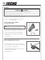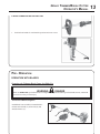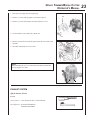
1
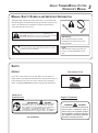
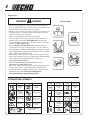
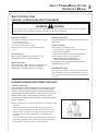
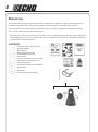
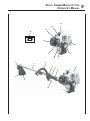
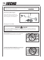
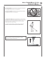
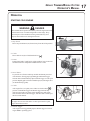
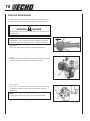
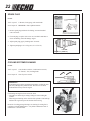
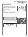
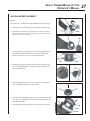
Grass Trimmer/Brush Cutter
Operator's Manual
MODEL
SRM-210
Serial Number 05295101 - 05999999
WARNING
DANGER
Read rules for safe operation and instructions carefully. ECHO provides an Operator's
Manual and a Safety Manual. Both must be read and understood for proper and safe
operation.
X7702275402
X770000672
12/03
2
INTRODUCTION
Welcome to the ECHO family. This ECHO product was designed and manufactured to provide long life and on-the-job
dependability. Read and understand this manual. You will find it easy to use and full of helpful operating tips and
SAFETY messages.
THE OPERATOR’S MANUAL
Read and understand this manual before operation. Keep it in a safe
place for future reference. It contains specifications and information for
operation, starting, stopping, maintenance, storage, and assembly
specific to this product.
THE SAFETY MANUAL
Read and understand this manual before operation. Keep it in a safe
place for future reference. It explains possible hazards involved with
the use of this product and what measures you should take to make
their use safer.
TABLE OF CONTENTS
Introduction ........................................................................ 2
- The Operator's Manual ............................................... 2
- The Safety manual ....................................................... 2
Manual Safety Symbols and Important Information ......... 3
Safety .................................................................................. 3
- Decals .......................................................................... 3
- International Symbols ................................................. 4
Safety Instructions ............................................................. 5
- Personal Condition and Safety Equipment ................. 5
- Extended Operation/Extreme Conditions ................... 5
- Equipment .................................................................. 6
- Safe Operation ............................................................ 7
Emission Control ................................................................ 7
Description ......................................................................... 8
- Contents ..................................................................... 8
Specifications .................................................................... 11
Assembly .......................................................................... 12
- Plastic Shield Installation .......................................... 12
- Nylon Head Installation ........................................... 12
- Front Handle Installation .......................................... 13
Pre-Operation ................................................................... 13
- Operation with Blades .............................................. 13
- Fuel ........................................................................... 16
Operation .......................................................................... 17
- Starting Cold Engine .................................................. 17
- Starting Warm Engine ................................................ 18
- Stopping Engine ........................................................ 19
Maintenance ..................................................................... 19
- Skill Levels ................................................................ 19
- Maintenance Intervals .............................................. 20
- Air Filter ................................................................... 21
- Fuel Filter ................................................................. 21
- Spark Plug ................................................................. 22
- Cooling System Cleaning .......................................... 22
- Exhaust System ........................................................ 23
- Carburetor Adjustment ............................................. 24
- Lubrication ................................................................ 26
- Nylon Line Replacement .......................................... 27
- Sharpening Metal Blades .......................................... 28
Troubleshooting ................................................................ 29
Storage .............................................................................. 30
Servicing Information ........................................................ 32
- Parts .......................................................................... 32
- ECHO Consumer Product Support .......................... 32
- Service ....................................................................... 32
- Warranty Card .......................................................... 32
- Additional or Replacement Manuals ........................ 32
Copyright© 2003 By Echo, Incorporated
All Rights Reserved.
Specifications, descriptions and illustrative material in this
literature are as accurate as known at the time of publication, but are subject to change without notice. Illustrations may include optional equipment and accessories,
and may not include all standard equipment.
GRASS TRIMMER/BRUSH CUTTER
OPERATOR'S MANUAL
3
MANUAL SAFETY SYMBOLS AND IMPORTANT INFORMATION
Throughout this manual and on the product itself, you will find safety
alerts and helpful, informational messages preceded by symbols or key
words. The following is an explanation of those symbols and key
words and what they mean to you.
This symbol accompanied by the words WARNING and
DANGER calls attention to an act or condition that can lead to
serious personal injury to operator and bystanders.
The circle with the slash symbol means whatever is shown
within the circle is prohibited.
IMPORTANT
The enclosed message provides
information necessary for the protection of the unit.
NOTE
This enclosed message provides tips
for use, care and maintenance of the
unit.
SAFETY
DECALS
Hot Surface Decal
Locate these safety decals on your unit. Make sure the decals are
legible and that you understand and follow the instructions on them. If
a decal cannot be read, a new one can be ordered from your ECHO
dealer. See PARTS ORDERING instructions for specific information.
P/N 89016006361
Shaft Decal
Spanish Decal
English Translation
ADVERTENCIA
PELIGRO
Esta unidad puede ser peligrosa y producir lesiones
personales graves si no se usa en forma adecuada.
Para reducir el riesgo de lesionarse, los operadores,
los ayudantes y los espectadores deben leer y
comprender el Manual Del Operador y los Manuales
89022809560 De Seguridad que se entregan escritos en español.
P/N 89022809560
WARNING
DANGER
This unit can be dangerous and cause
serious injury if improperly used. to
reduce injury risk to operator, helpers
and bystanders, read and understand
the Operator's and Safety Manuals,
which are provided in Spanish.
4
Shaft Decal
WARNING
DANGER
P/N 89016054130
• This unit can be dangerous and cause serious injury if improperly
used. To reduce injury risk to operator, helpers and bystanders, read
and understand the Operator's and Safety manuals.
• Blindness can occur from objects that are thrown or ricocheted even
with shield in place. Operators, helpers and bystanders must wear
ANSI Z87.1 approved eye protection.
• Always wear hearing protection when operating unit.
• Prevent accidental contact with unit and any cutting attachment.
Maintain a 50 ft. (15M) radius, DANGER ZONE surrounding the
operator. ONLY the operator, dressed in proper protective clothing
should be in the DANGER ZONE.
• Beware of KICKOUT (blade thrust) when using blades. Special
precautions are necessary for blade operation, see your Operator's
and Safety Manuals. ONLY install ECHO approved blades on Brush
Cutters (SRM) models equipped with proper blade shield, U-handles,
harness, blade collar, nut and cotter pin.
• Blade/Cutting attachment does not stop immediately after releasing
throttle. Keep hands and feet clear of blade/cutting attachment unless
engine is shut off and cutting attachment is not moving.
• INSPECT BLADES BEFORE USE.
• DO NOT USE DAMAGED, CRACKED, BENT, DULL OR
IMPROPERLY SHARPENED BLADES.
• Do not remove shields, modify the unit or install attachments or parts
not approved by ECHO. Approved attachment information and
replacement Operator's and Safety Manuals are available from your
ECHO dealer or by writing: ECHO, INCORPORATED,
400 OAKWOOD RD., LAKE ZURICH, IL 60047.
INTERNATIONAL SYMBOLS
SYMBOL
DESCRIPTION
SYMBOL
DESCRIPTION
SYMBOL
DESCRIPTION
SYMBOL
DESCRIPTION
"WARNING, SEE
OPERATOR'S
MANUAL
Hot
Surface
Emergency
Stop
Fuel and oil
mixture
Wear eye, ear
and head
protection
Finger Severing
Carburetor
Adjustment
- High speed
mixture
Primer
Bulb
Wear hand and
foot protection
DO NOT allow
flames or sparks
near fuel.
Carburetor
Adjustment
- Idle speed
Safety/Alert
DO NOT smoke
near fuel.
Carburetor
Adjustment
- Low speed
mixture
Keep bystanders and helpers
away 15 m (50 ft.).
Choke Control
"Run"
Position
(Choke Open)
Ignition
ON/
OFF
Do not use
blades. String
line only
Choke Control
"Cold Start"
Position
(Choke Closed)
GRASS TRIMMER/BRUSH CUTTER
OPERATOR'S MANUAL
5
SAFETY INSTRUCTIONS
PERSONAL CONDITION AND SAFETY EQUIPMENT
WARNING
DANGER
Users of this product risk injury to themselves and others if the unit is used improperly and/or safety precautions
are not followed. Proper clothing and safety gear must be worn when operating unit.
Physical Condition
Hearing Protection
Your judgment and physical dexterity may not be good:
• if you are tired or sick,
• if you are taking medication,
• if you have taken alcohol or drugs.
Operate unit only if you are physically and mentally
well.
ECHO recommends wearing hearing protection whenever
unit is used.
Eye Protection
Wear eye protection that meets ANSI Z87.1 or CE
requirements whenever you operate the unit.
Hand Protection
Wear no-slip, heavy-duty work gloves to improve your
grip on the blower handle. Gloves also reduce the
transmission of machine vibration to your hands.
Proper Clothing
Wear snug fitting, durable clothing;
• Pants should have long legs, shirts with long sleeves.
• DO NOT WEAR SHORTS,
• DO NOT WEAR TIES, SCARVES, and JEWELRY.
Wear sturdy work shoes with nonskid soles:
• DO NOT WEAR OPEN TOED SHOES,
• DO NOT OPERATE UNIT BAREFOOTED.
Keep long hair away from engine and blower intake.
Retain hair with cap or net.
Hot Humid Weather
Heavy protective clothing can increase operator fatigue,
which may lead to heat stroke. Schedule heavy work for
early morning or late afternoon hours when temperatures
are cooler.
EXTENDED OPERATION/EXTREME CONDITIONS
Vibration and Cold
It is believed that a condition called Raynaud’s Phenomenon, which
affects the fingers of certain individuals, may be brought about by
exposure to vibration and cold. Exposure to vibration and cold may
cause tingling and burning sensations, followed by loss of color and
numbness in the fingers. The following precautions are strongly
recommended, because the minimum exposure, which might trigger the
ailment, is unknown.
• Keep your body warm, especially the head, neck, feet, ankles, hands,
and wrists.
• Maintain good blood circulation by performing vigorous arm
exercises during frequent work breaks, and also by not smoking.
• Limit the hours of operation. Try to fill each day with jobs where
operating the unit or other hand-held power equipment is not
required.
• If you experience discomfort, redness, and swelling of the fingers
followed by whitening and loss of feeling, consult your physician
before further exposing yourself to cold and vibration.
6
Repetitive Stress Injuries
It is believed that overusing the muscles and tendons of the fingers,
hands, arms, and shoulders may cause soreness, swelling, numbness,
weakness, and extreme pain in those areas. Certain repetitive hand
activities may put you at a high risk for developing a Repetitive Stress
Injury (RSI). An extreme RSI condition is Carpal Tunnel Syndrome
(CTS), which could occur when your wrist swells and squeezes a vital
nerve that runs through the area. Some believe that prolonged exposure to vibration may contribute to CTS. CTS can cause severe pain for
months or even years.
To reduce the risk of RSI/CTS, do the following:
• Avoid using your wrist in a bent, extended, or twisted position.
Instead try to maintain a straight wrist position. Also, when grasping, use your whole hand, not just the thumb and index finger.
• Take periodic breaks to minimize repetition and rest your hands.
• Reduce the speed and force with which you do the repetitive
movement.
• Do exercise to strengthen the hand and arm muscles.
• Immediately stop using all power equipment and consult a doctor if
you feel tingling, numbness, or pain in the fingers, hands, wrists, or
arms. The sooner RSI/CTS is diagnosed, the more likely permanent
nerve and muscle damage can be prevented.
EQUIPMENT
WARNING
DANGER
Use only ECHO approved attachments. Serious injury may result from the use of a non-approved attachment
combination. ECHO, INC. will not be responsible for the failure of cutting devices, attachments or accessories which
have not been tested and approved by ECHO. Read and comply with all safety instructions listed in this manual and
safety manual.
• Check unit for loose/missing nuts, bolts, and screws. Tighten and/or
replace as needed.
• Inspect fuel lines, tank, and area around carburetor for fuel leaks. DO
NOT operate unit if leaks are found.
• Inspect shield for damage and ensure that the cut-off knife issecurely
in place. Replace if either is damaged or missing.
• Check that the cutting attachment is firmly attached and in safe
operating condition.
• Check that front loop handle and shoulder strap/ or shoulder/
waist harness are adjusted for safe, comfortable operation. See
Assembly Section for proper adjustment.
GRASS TRIMMER/BRUSH CUTTER
OPERATOR'S MANUAL
SAFE OPERATION
WARNING
DANGER
Do not operate this product indoors or in inadequately ventilated
areas. Engine exhaust contains poisonous emissions and can
cause serious injury or death.
Read the Manuals
• Provide all users of this equipment with the Operator’s Manual and
Safety Manual for instructions on Safe Operation.
Clear the Work Area
• Spectators and fellow workers must be warned, and children and
animals prevented from coming nearer than 15 m (50 ft.) while the unit
is in use.
Keep a Firm Grip
• Hold the front and rear handles with both hands, with thumbs and
fingers encircling the handles.
Keep a Solid Stance
• Maintain footing and balance at all times. Do not stand on slippery,
uneven or unstable surfaces. Do not work in odd positions or on
ladders. Do not over reach.
Avoid Hot Surfaces
• Keep exhaust area clear of flammable debris. Avoid contact during
and immediately after operation.
EMISSION CONTROL
EPA Phase 2
The emission control system for this engine is EM (Engine
Modification).
Emission Control Label (located on Engine) (EXAMPLE
ONLY, information on label varies by FAMILY).
IMPORTANT ENGINE INFORMATION
ENGINE FAMILY: 3EHXS.0214EA DISPLACEMENT: 21.2 CC
EMISSION COMPLIANCE PERIOD: 300 HOURS
THIS ENGINE MEETS U.S. EPA PH2 EMISSION REGULATIONS FOR SMALL NONROAD ENGINE. REFER TO
OWNER'S MANUAL FOR MAINTENANCE SPECIFICATIONS
AND ADJUSTMENTS.
PRODUCT EMISSION DURABILITY
The 300 hour emission durability compliance period is the time span selected by the manufacturer certifying the
engine emissions output meets applicable emissions regulations, provided that approved maintenance procedures
are followed as listed in the Maintenance Section of this manual.
7
8
DESCRIPTION
The ECHO product you purchased has been partially assembled for your convenience. Due to packaging restrictions,
installation of the plastic debris shield, nylon line head, and positioning of the front handle may be necessary.
After opening the carton, check for damage. Immediately notify your retailer or ECHO Dealer of damaged or missing
parts. Use the contents list to check for missing parts.
* Some units may be factory pre-assembled. No assembly tools are needed and the nylon line head, plastic debris shield,
and mounting hardware, shown in the contents list, are pre-assembled to the unit. Only the front handle may need to be
re-positioned for comfortable operation.
CONTENTS
______1
______1
______1
______1
______1
______1
______1
______1
* ___ 1
* ___ 1
* ___ 1
* ___ 1
* ___ 3
-
Power Head / Drive Shaft Assembly
Operator's Manual
Safety Manual
Warranty Registration Card
Limited Warranty Statement
Safety Glasses
Echo Power Blend TM 2-stroke oil sample
Head locking tool, P/N 89751801131
Nylon Trimmer Head
T - Wrench 17x19 mm, P/N 89541008030
Plastic shield
Shield plate
5mm x 16mm screws (shield mtg.)
*
GRASS TRIMMER/BRUSH CUTTER
OPERATOR'S MANUAL
12
11
19
20
Safety
Video
18
13
17
14
16
7
6
15
5
1
4
3
2
8
9
10
9
10
1. POWER HEAD - Includes the Engine, Clutch, Fuel System, Ignition System and Recoil Starter.
2. GRIP - Rear (right hand) handle.
3. THROTTLE TRIGGER LOCKOUT - This lever must be held during starting. Operation of the throttle trigger is
prevented unless throttle trigger lockout lever is engaged.
4. STOP SWITCH - "SLIDE SWITCH" mounted on top of the Throttle Trigger Housing. Move switch FORWARD to
RUN, BACK to STOP.
5. FRONT HANDLE - The Front (loop) handle is loosely assembled to the Drive Shaft assembly and must be positioned
for proper cutting attitude and operator comfort.
6. DRIVE SHAFT ASSEMBLY - Includes the Gear Housing assembly, flex drive cable and Safety Decal.
7. NYLON CUTTER HEAD - Contains replaceable nylon trimming line that advances when the trimmer head is tapped
against the ground while the head is turning at normal operating speed.
8. CUT-OFF KNIFE - Automatically trims line to the correct length: 5" after head is tapped on the ground. If trimmer is
operated without a cut-off knife the line will become too long, the engine will overheat and engine damage may occur.
9. PLASTIC DEBRIS SHIELD ASSEMBLY - Included in plastic bag (co-pack). MUST be installed on unit before use,
see Assembly Instructions. Shield assembly includes the Cut-Off Knife. Mounts on the Gear Housing Assembly just
above the cutting attachment. Helps protect the operator by deflecting debris produced during the trimming operation.
This shield must be replaced with the steel shield for blade use.
10. THROTTLE TRIGGER - Spring loaded to return to idle when released. During acceleration, press trigger gradually for
best operating technique.
11. SPARK PLUG - Provides spark to ignite fuel mixture.
12. TOP GUARD - Protects arm from the hot engine.
13. SPARK ARRESTOR - CATALYTIC MUFFLER / MUFFLER -The muffler or catalytic muffler controls exhaust noise
and emission. The spark arrestor screen prevents hot, glowing particles of carbon from leaving the muffler. Keep
exhaust area clear of flammable debris.
14. FUEL TANK - Contains fuel and fuel filter.
15. I-30 RECOIL STARTER/HANDLE - i-30 spring-assisted recoil starter requires 30% less pulling force than standard
recoil starter. Pull handle slowly until starter engages, then quickly and firmly. When engine starts, return handle
slowly. DO NOT let handle snap back or damage to unit will occur.
16. FUEL TANK CAP - Covers and seals fuel tank opening.
17. PRIMER BULB - Pumping primer bulb before starting engine draws fresh fuel from the fuel tank priming the carburetor
for starting. Pump primer bulb until fuel is visible and flows freely in the clear fuel tank return line. Pump bulb an
additional 4 or 5 times.
18. AIR CLEANER - Contains replaceable filter element.
19.CHOKE - Located at the rear of the air cleaner housing. Move choke lever to "Cold Start" (
starting. Move choke lever to "Run" (
) to close choke for cold
) position to open choke.
20. SAFETY VIDEO - (Not included with unit) P/N 99922202540 English version and P/N 99922203508 Spanish version are
available at a cost of $5.00 from ECHO, INC. or any authorized ECHO dealer. The video overviews safety precautions
and proper operating techniques and is supplemental to the Safety Manual. Read and understand the Safety Manual
for complete information on safe operation.
GRASS TRIMMER/BRUSH CUTTER
OPERATOR'S MANUAL
SPECIFICATIONS
MODEL ----------------------------------------------------- SRM-210
Length ------------------------------------------------------- 1770 mm (69.7 in.)
Width -------------------------------------------------------- 250 mm (9.84 in.)
Height ------------------------------------------------------- 325 mm (12.8 in.)
Weight (dry) w/cutter head ------------------------------- 4.8 kg (10.7 lb.)
Engine Type ------------------------------------------------ Air cooled, two-stroke, single cylinder gasoline engine
Bore ---------------------------------------------------------- 32.2 mm (1.27 in.)
Stroke -------------------------------------------------------- 26.0 mm (1.02 in.)
Displacement ----------------------------------------------- 21.2 cc (1.29 cu. in.)
Exhaust ------------------------------------------------------ Spark Arrestor Muffler
Carburetor -------------------------------------------------- Zama model w/purge pump
Ignition System -------------------------------------------- Flywheel magneto, capacitor discharge ignition type
Spark Plug -------------------------------------------------- NGK BPM-8Y Gap 0.65 mm (0.026 in.)
Fuel ---------------------------------------------------------- Mixed (Gasoline and Two-stroke Oil)
Fuel/Oil Ratio ----------------------------------------------- 50:1 two-stroke air cooled engine oil
Gasoline ----------------------------------------------------- 89 Octane unleaded. DO NOT use fuel containing methyl alcohol,
more than 10% ethyl alcohol or 15% MTBE.
Oil ------------------------------------------------------------ Power Blend TM Premium Universal 2-Stroke Oil
Fuel Tank Capacity ---------------------------------------- 0.45 lit. (15.2 US fl. oz.)
Recoil Starter System -------------------------------------- i-30 Automatic Recoil Starter
Clutch ------------------------------------------------------- Centrifugal Type
Drive Shaft -------------------------------------------------- 1/4 in. Flex Shaft
Rotating Direction ----------------------------------------- Counter-Clockwise viewed from top
Cutter Head ------------------------------------------------- Nylon line head (2-line) with .095 Crossfire™ Line capacity
6m (20 ft.)
Handle* ----------------------------------------------------- Front - Loop and Right Rear Handle w/rubber grips
Shoulder Harness ------------------------------------------ Optional
Idle Speed RPM -------------------------------------------- 2,400 - 3,200
Wide Open Throttle Speed (W.O.T.) RPM ------------- 8,000 - 9,000
* Install and use U-Handle when operating any model with blade.
11
12
ASSEMBLY
WARNING
DANGER
Use only ECHO approved attachments. Serious injury may result from using non-approved attachment combinations.
Read and comply with all safety instructions listed in this manual and attachment manual.
ECHO, INC. will not be responsible for the failure of cutting devices, attachments, or accessories which have not
been tested and approved by ECHO for use with these units.
Tools Required: Screwdriver, Head Locking Tool, 17x19mm T-Wrench
Parts Required: Plastic Shield, Shield Plate, three (3) 5mm x 16mm
screws, Nylon Line Head
PLASTIC SHIELD INSTALLATION
(For Nylon Line Operation)
NOTE
The plastic shield is for use with the Nylon Line Head only.
Install Metal Shield when using plastic or metal blades.
1. Remove plastic sleeve and upper plate (A) from PTO shaft.
2. Install the shield on the bottom of the bearing housing flange.
3. Place shield plate (B) on shield, align holes and install three (3)
5x16 mm screws.
B
4. Install upper plate (A).
NYLON LINE HEAD INSTALLATION
C
1. Align hole in upper plate with notch in edge of gear housing and
insert head locking tool (C). Remove plastic sleeve from PTO shaft.
2. Be sure upper plate (A) remains on PTO shaft.
3. Thread line head onto PTO shaft by turning it counter clockwise
until head is tight against upper plate.
4. Remove locking tool (C).
A
GRASS TRIMMER/BRUSH CUTTER
OPERATOR'S MANUAL
FRONT HANDLE INSTALLATION
1.
Position front handle for comfortable operation and secure screws.
PRE - OPERATION
OPERATION WITH BLADES
Preparing the Trimmer/Brush Cutter for Blade Use
WARNING
DANGER
Blade use DEMANDS specific Brush Cutter configuration. Operation without specified shield, harness, and handle
can result in serious personal injury.
Grass/Weed Blades Require:
Install Blade Conversion Kit, P/N 99944200415 Includes metal shield (A), barrier bar (B), and
shoulder harness (C).
A
B
C
13
14
NOTE
The Barrier Bar is used to restrict rearward movement of the unit. The Barrier Bar is NOT A HANDLE and should not
be gripped when using or carrying the unit.
Brush/Clearing Blades Require:
D
Install U-Handle / Blade Conversion Kit, P/N
99944200521 - Includes metal shield (A), shoulder
harness with hip pad (C), and U-Handles (D).
A
C
Choosing the Correct Blade
WARNING
DANGER
The type of Blade used MUST be matched to the type and size of material cut. An improper or dull blade can
cause serious personal injury. Blades MUST be sharp. Dull blades increase the chance of kick out and injury
to yourself and bystanders.
Plastic/Nylon Blades may be used where ever the nylon line head
is used. DO NOT use this blade for heavy weeds or brush!
8 Tooth Weed/Grass Blade P/N 69600120331 is designed for grass,
garden debris and thick weeds. DO NOT use this blade for brush or
heavy woody growth, 19 mm (3/4 in.) diameter or larger.
GRASS TRIMMER/BRUSH CUTTER
OPERATOR'S MANUAL
80 Tooth Brush Blade (P/N 69500120331) is designed for cutting brush
and woody growth up to 64 mm (2-1/2 in.) diameter.
22 Tooth Clearing Blade (99944200130) is designed for dense thickets
and saplings up to 64 mm (2-1/2 in.) diameter.
Use Shoulder/Waist Harness (P/N 99944200200) Use of the Shoulder/
Waist Harness is recommended for ALL Trimmer/Brush Cutter use. The
Shoulder/Waist Harness suspends the trimmer from the operator's
shoulder and reduces operator fatigue.
The restrictive harness enhances operator safety by reducing the
possibility of blade contact with the operator's hands and feet.
NOTE
In case of Emergency, pull up on the Quick Release Collar to
disconnect the trimmer from the harness.
15
16
FUEL
Fuel Requirements
Gasoline - Use 89 Octane [R+M/2] (mid grade or higher) gasoline
known to be good quality. Gasoline may contain up to 15% MTBE
(methyl tertiary-butyl ether). Gasohol containing methyl (wood) alcohol
is NOT approved.
Two Stroke Oil - A two-stroke engine oil meeting ISO-L-EGD (ISO/CD
13738) and J.A.S.O. FC Standards must be used. Echo brand premium
Power Blend TM Universal 2-Stroke Oil meets these standards. Engine
problems due to inadequate lubrication caused by failure to use an
ISO-L-EGD and J.A.S.O. FC certified oil, such as Echo premium Power
Blend TM, will void the two-stroke engine warranty. (Emission related
parts only are covered for two years, regardless of two-stroke oil used,
per the statement listed in the Emission Defect Warranty Explanation.)
IMPORTANT
Spilled fuel is a leading cause of
hydrocarbon emissions. Some states
may require the use of automatic fuel
shut-off containers to reduce fuel
spillage. Contact your ECHO dealer for
ordering information.
After Refueling
• Wipe any spilled fuel from the unit.
• Move at least 3 m (10 ft.) from refueling
location before starting the engine.
IMPORTANT
Echo premium Power Blend TM Universal 2-Stroke Oil may be mixed
at 50:1 ratio for application in all Echo engines sold in the past
regardless of ratio specified in those manuals.
After use
• DO NOT store a unit with fuel in its tank.
Leaks can occur. Return unused fuel to an
approved fuel storage container.
Mixing Instructions
1. Fill an approved fuel container with half of the required amount of
gasoline.
2. Add the proper amount of 2-stroke oil to gasoline.
3. Close container and shake to mix oil with gasoline.
4. Add remaining gasoline and remix.
5. Install fuel container cap and wipe any spilled fuel from container
and surrounding area.
Storage - Fuel storage laws vary by locality.
Contact your local government for the laws
affecting your area. As a precaution, store
fuel in an approved, airtight container. Store
in a well-ventilated, unoccupied building,
away from sparks and flames. Do not store
fuel longer than 30 days.
Handling Fuel
WARNING
DANGER
Fuel is VERY flammable. Use extreme care when mixing, storing or
handling or serious personal injury may result.
• Use an approved fuel container.
• DO NOT smoke near fuel.
• DO NOT allow flames or sparks near fuel.
• Fuel tanks/cans may be under pressure. Always loosen fuel caps
slowly allowing pressure to equalize.
• NEVER refuel a unit when the engine is HOT!
• NEVER refuel a unit with the engine running.
• DO NOT fill fuel tanks indoors. ALWAYS fill fuel tanks outdoors
over bare ground.
• Securely tighten fuel cap after refueling.
• Inspect for fuel leakage. If fuel leakage is found, do not start or
operate unit until leakage is repaired.
IMPORTANT
Stored fuel ages. Do not mix more fuel
than you expect to use in thirty (30)
days, ninety (90) days when a fuel
stabilizer is added.
IMPORTANT
Stored two-stroke fuel may separate.
ALWAYS shake fuel container thoroughly before each use.
GRASS TRIMMER/BRUSH CUTTER
OPERATOR'S MANUAL
OPERATION
STARTING COLD ENGINE
WARNING
DANGER
The attachment will operate immediately when the engine starts and
could result in loss of control and possible serious injury. Keep
movable parts of the attachment off the ground and away from
objects that could become entangled or thrown.
A
1. Stop Switch
Move stop switch button (A) forward away from the STOP position.
2. Choke
Move choke lever (B) to Cold Start Position (
).
B
3. Primer
Pump primer bulb (C) until fuel is visible and flows freely in the clear
fuel tank return line. Pump bulb an additional 4 or 5 times.
4. Recoil Starter
Lay the unit on a flat area and keep movable attachment parts clear
of all obstacles. Firmly grasp right hand grip and throttle trigger
lockout with left hand and fully depress throttle trigger to wide open
position. Rapidly pull recoil starter handle/rope (D) until engine fires
(or maximum five [5] pulls).
C
5. Choke
After engine fires (or 5 pulls), move choke lever back to Run (
)
position. Hold throttle trigger and throttle trigger lockout fully
depressed, and pull recoil starter starter handle/rope until engine
starts and runs. Release throttle trigger, and allow unit to warm up at
idle for several minutes.
NOTE
If engine does not start with choke in “Run” position after 5 pulls,
repeat instructions 4 and 5.
6. Throttle Trigger
After engine warm-up, gradually depress throttle trigger to increase
engine RPM to operating speed.
D
17
18
STARTING WARM ENGINE
The starting procedure is the same as Cold Start except DO NOT close
the choke, and do not depress throttle trigger to wide open position.
WARNING
DANGER
The attachment should not move at idle, otherwise serious personal
injury may result.
A
NOTE
If attachment moves, readjust carburetor according to “Carburetor
Adjustment” instructions in this manual or see your ECHO Dealer.
1. Stop Switch
Move stop switch button (A) away from the STOP position.
2. Primer
Pump primer bulb (C) until fuel is visible and flows freely in the clear
fuel tank return line. Pump bulb an additional 4 or 5 times.
C
3. Recoil Starter
Lay the unit on a flat area and keep movable attachment parts clear
of all obstacles. Rapidly pull recoil starter handle/rope (D) until
engine fires.
NOTE
If engine does not start after 5 pulls, use Cold Start Procedure.
D
GRASS TRIMMER/BRUSH CUTTER
OPERATOR'S MANUAL
19
STOPPING ENGINE
1. Throttle
Release throttle and allow engine to return to idle before shutting off
engine.
A
2. Stop Switch
Move stop switch button (A) backward to STOP position.
WARNING
DANGER
If engine does not stop when stop switch is moved to STOP
position, close choke - COLD START position - to stall engine.
Have your ECHO dealer repair stop switch before using trimmer
again.
MAINTENANCE
Your ECHO unit is designed to provide many hours of trouble free service. Regular scheduled maintenance will help
your unit achieve that goal. If you are unsure or are not equipped with the necessary tools, you may want to take your
unit to an ECHO Service Dealer for maintenance. To help you decide whether you want to DO-IT-YOURSELF or have
the ECHO Dealer do it, each maintenance task has been graded. If task is not listed, see your ECHO Dealer for repairs.
SKILL LEVELS
Level 1 =
Level 2 =
Level 3 =
Easy to do. Most required tools come with unit.
Moderate difficulty. Some specialized tools may be required.
Experience required. Specialized tools are required. Echo recommends that the unit be returned to your
ECHO dealer for service.
ECHO offers REPOWERTM Maintenance Kits and Parts to make your maintenance job easier. Just below each task
heading are listed the various part numbers required for that task. See your ECHO dealer for these parts.
20
MAINTENANCE INTERVALS
COMPONENT/
SYSTEM
MAINTENANCE
PROCEDURE
REQ'D
SKILL
LE V E L
DAILY OR
BEFORE
U SE
EVERY
R E FU E L
3
MONTHS
OR 90
HOURS
6
MONTHS
OR 270
HOURS
YEARLY
600
HOURS
Recommended Echo Dealer Maintenance Procedures
Cylinder Exhaust Port
Inspect/Clean/Decarbon
3
I/C
Do-It-Yourself Maintenance Procedures
Air Filter
Inspect/Clean/Replace
1
I/C
Choke
Inspect/Clean
2
I/C
Fuel Filter
Inspect/Replace
1
Fuel System, leaks
Inspect/Replace
1
I*
Cooling System
Inspect/Clean
2
I/C
Muffler Spark Arrestor
Inspect/Replace
2
I/R*
Drive Shaft (Flex
Cable Models)
Grease
2
I (1)
Gear Housing
Grease
2
I (2)
Recoil Starter Rope
Inspect/Clean
1
Spark Plug
Inspect/Clean
2
Screws/Nuts/Bolts
Inspect/Tighten/Replace
1
R*
I/R*
I
I
I
I/C*
I/C
R*
I/R*
MAINTENANCE PROCEDURE LETTER CODES: I = INSPECT, R = REPLACE, C = CLEAN
IMPORTANT NOTE - Time intervals shown are maximum. Actual use and your experience will determine the frequency of required
maintenance.
MAINTENANCE PROCEDURE NOTES:
(1) Apply ECHO® LUBETM every 25 hours of use.
(2) Apply ECHO® LUBETM every 50 hours of use.
* All recommendations to replace are based on the finding of damage or wear during inspection..
GRASS TRIMMER/BRUSH CUTTER
OPERATOR'S MANUAL
AIR FILTER
Level 1.
Tools required: 25 - 50 mm (1 - 2 in.) Cleaning Brush
Parts required: 90008 REPOWERTM AIR & FUEL FILTER KIT.
]). This prevents dirt from
1. Close choke (Cold Start Position [
entering the carburetor throat when the air filter is removed.
Brush accumulated dirt from the air cleaner area.
2. Remove the air cleaner cover. Clean and inspect the element for
damage. If element is fuel soaked and very dirty, replace.
3. If element can be cleaned and reused, be certain it:
•still fits the cavity in the air cleaner cover.
•is installed with the original side out.
NOTE
Carburetor adjustment may be needed after air filter cleaning/
replacement.
FUEL FILTER
Level 1.
Tools required: 200 - 250 mm (8 - 10 in.) length of wire with one end
bent into a hook, clean rag, funnel, and an approved
fuel container
Parts required: 90008 REPOWERTM AIR & FUEL FILTER KIT.
WARNING
DANGER
Fuel is VERY flammable. Use extreme care when mixing, storing or
handling, or serious personal injury may result.
1. Use a clean rag to remove loose dirt from around fuel cap and
empty fuel tank.
2. Use the “fuel line hook” to pull the fuel line and filter from the
tank.
3. Remove the filter from the line and install the new filter.
21
22
SPARK PLUG
Level 2.
Tools required: T-Wrench, feeler gauge, soft metal brush
Parts Required: REPOWERTM Tune-Up Kit P/N 90074
1. Remove spark plug and check for fouling, worn and rounded
center electrode.
2. Clean the plug or replace with a new one. DO NOT sand blast to
clean. Remaining sand will damage engine.
3. Adjust spark plug gap by bending outer electrode.
4. Tighten spark plug to 145 - 155 kg/cm (125 - 135 in. lb.).
0.65 mm
(0.026 in.)
COOLING SYSTEMS CLEANING
Level 2.
Tools required: Cross-head screwdriver, 3 and 4 mm hex wrench,
25 - 50mm (1 - 2 in.) cleaning brush.
Parts Required: None if you are careful.
IMPORTANT
To maintain proper engine operating temperatures, cooling air must
pass freely through the cylinder fin area. This flow of air carries
combustion heat away from the engine.
Overheating and engine seizure can occur when:
• Air intakes are blocked, preventing cooling air from reaching the
cylinder.
• Dust and grass build up on the outside of the cylinder. This build up
insulates the engine and prevents the heat from leaving.
Removal of cooling passage blockages or cleaning of cooling fins is
considered “Normal Maintenance.” Any failure attributed to lack of
maintenance is not warranted.
GRASS TRIMMER/BRUSH CUTTER
OPERATOR'S MANUAL
1. Disconnect spark plug lead from spark plug.
2. Remove (1) screw from top guard (A), and remove guard.
B
3. Remove (3) screws from engine cover (B), and remove cover.
4. Use the brush to remove dirt form cylinder fins.
A
5. Remove grass and leaves from the grid between the recoil starter and
fuel tank.
6. Assemble components in reverse order.
NOTE
When installing the cover, be certain the metal deflector shield tab
is in the engine cover slots.
EXHAUST SYSTEM
Spark Arrestor Screen
Level 2.
Tools required: Cross-head screwdriver, soft metal brush.
Parts Required: Screen P/N 14586240630,
Gasket P/N 14586642031
23
24
1. Remove engine cover. See “Cleaning Cooling System” page 23 for
instructions.
2. Remove spark arrestor screen cover (A), gasket (B), and screen (C)
from muffler body.
3. Clean carbon deposits from muffler components.
4. Replace screen if it is cracked, plugged or has holes burned through.
5. Reassemble in reverse order of removal. Make sure screen is
positioned properly before tightening screws.
NOTE
When installing the cover, be certain the metal deflector shield tab
is in the engine cover slots.
Cylinder Exhaust Port
Level 3
IMPORTANT
The cylinder exhaust port must be inspected and cleaned of
excess carbon every 3 months or 90 hours of operation in order
to maintain this engine within the emissions durability period.
ECHO strongly recommends that you return your unit to your
ECHO dealer for this important maintenance service.
C
B
A
GRASS TRIMMER/BRUSH CUTTER
OPERATOR'S MANUAL
25
CARBURETOR ADJUSTMENT
Engine Break-In
New engines must be operated for a minimum of two tanks of fuel
before carburetor adjustments can be made. During the break-in period,
your engine performance will increase and exhaust emissions will
stabilize. Idle speed can be adjusted as required.
High Altitude Adjustment
High altitude adjustment is not required for proper operation of this
engine.
Idle Speed Adjustment
Idle speed adjustment may be required periodically to comply with
specifications for this unit. See "Specifications," for correct idle speed.
Level 2.
Tools required:
Screwdriver, Tachometer (ECHO P/N 99051130017).
NOTE
Every unit is run at the factory and the carburetor is set in compliance with emission regulations. This carburetor does not have
acceleration and high speed adjustment needles.
1. Check idle speed using a tachometer, and reset if necessary. Turn
idle screw (A) clockwise to increase idle speed; counter clockwise to
decrease idle speed.
WARNING
DANGER
When carburetor adjustment is completed, blades should not move
at idle, otherwise serious personal injury may result.
A
26
LUBRICATION
Level 1.
Tools required: 8 mm Open End Wrench, Cross Head Screwdriver,
Clean rag
Parts Required: ECHO® LUBETM 8 oz. (P/N 91014) or Lithium Base
Grease.
Gear Housing
A
A
1. Clean all loose debris from gear box.
2. Remove plug (A) and check level of grease.
3. Add grease if necessary, DO NOT over fill.
Drive Shaft
1. Loosen two (2) screws (B) and remove center locating screw (C).
Pull gear box and shield from drive shaft housing.
2. Pull flexible cable from the drive shaft housing, wipe clean and
recoat with a thin coating [15 ml (1/2 oz.)] of grease.
3. Slide the flexible cable back in the drive housing. DO NOT get
dirt on the flex cable.
4. Install the gear housing and shield assembly.
C
B
B
GRASS TRIMMER/BRUSH CUTTER
OPERATOR'S MANUAL
NYLON LINE REPLACEMENT
B
Level 1.
Parts Required: ECHO 0.095" Nylon Trimmer Line 6 m (20 ft.) long.
1. Shut engine off. Lay unit on the ground with head assembly up.
2. Hold drum (A) and firmly turn spool (B) CW (clockwise) until it
disengages from the inner drive. Pull spool from drum. DO NOT
push in on spool when turning.
A
A
B
3. Use one piece of new nylon line (C) 6 m (20 ft.) long and thread
through the molded loop (D) on the spool. Pull line tight and
adjust so one end is 15 cm (6 in.) longer than the other.
C
4. Hold the spool, opening toward you. Place index finger between
the two strands and wind line, tightly and evenly, in direction of
arrow (E) marked "CC".
E
CC
5. Stop when approximately 15-20 cm (6-8 in.) line (C) remains and
place ends of line in notches (F) in spool (B).
B
F
6. Feed ends of line through housing eyelets (G) and place spool (B)
over drive (H). Align pegs (I) on drive with notches in spool, and
push spool into drum.
D
G
F
I
7. Pull on both lines until they come free from notches (F) in spool.
B
H
G
27
28
8. Hold drum (A) firmly and turn spool (B) CCW (counterclockwise)
until it stops. DO NOT push in on spool when turning.
B
A
9. Pull both lines out and trim to cut-off knife length.
SHARPENING METAL BLADES
Three styles of metal blades are approved for use on the ECHO Brush
Cutter. The 8-tooth blade can be sharpened during normal maintenance.
The clearing blade and 80 tooth blade require professional service.
Before sharpening, CLOSELY inspect blade for cracks (look at the
bottom of each tooth and the center mounting hole closely), missing
teeth and bending. If ANY of these problems are discovered, replace
the blade.
When sharpening a blade, always remove the same amount of materials
from each tooth to maintain balance. A blade that is not balanced will
cause unsafe handling due to vibration and can result in blade failure.
Tool required:
Flat file (preferred). Electric grinder if special care is
used. Round (rat tail) file for gullet (radius).
1. File each tooth at a 30 degree angle a specific number of times,
eg. 4 strokes per tooth. Work your way around the blade until
all teeth are sharp.
2. DO NOT file the 'gullet' (radius) of the tooth with the flat file.
The radius must remain. A sharp corner will lead to a crack and
blade failure.
IMPORTANT
If an electric grinder is used, use care not to overheat teeth, do not
allow tips/tooth to glow red or turn blue. DO NOT place blade in
cooling water. This will change the temper of the blade and could
result in blade failure.
3. After sharpening teeth, check each tooth radius for evidence of a
square (sharp) corner. Use the round (rat tail) file to renew the
radius.
GRASS TRIMMER/BRUSH CUTTER
OPERATOR'S MANUAL
TROUBLESHOOTING
ENGINE PROBLEM TROUBLESHOOTING CHART
Problem
Engine cranks
starts hard/
doesn't
start
Engine runs,
but dies or
does not
accelerate
properly
Engine does
not
crank
C h eck
Status
Fuel at carburetor
No fuel at carburetor
Fuel at cylinder
C au se
Remedy
Fuel strainer clogged
Fuel line clogged
Carburetor
Clean or replace
Clean or replace
See your Echo dealer
No fuel at cylinder
Carburetor
See your Echo dealer
Muffler wet with fuel
Fuel Mixture too rich
Open choke
Clean/replace air filter
Adjust carburetor
See your Echo dealer
Spark at end
of plug wire
No spark
Stop switch off
Electrical problem
Interlock switch
Turn switch to ON
See your Echo dealer
See your Echo dealer
Spark at plug
No spark
Spark gap incorrect
Covered with carbon
Fouled with fuel
Plug defective
Adjust to 0.70mm (0.026 in.)
Clean or replace
Clean or replace
Replace plug
Air filter
Air filter dirty
Normal wear
Clean or replace
Fuel filter
Fuel filter dirty
Contaminants/residues in
fuel
Replace
Fuel vent
Fuel vent plugged
Spark Plug
Plug dirty/worn
Carburetor
Improper adjustment
Cooling System
Cooling system
dirty/plugged
Spark Arrestor
Screen
Spark arrestor screen
plugged
N/A
N/A
WARNING
Contaminants/residues in fuel Clean or replace
Normal wear
Clean and adjust or replace
Vibration
Adjust
Extended operation in
dirty/dusty locations
Clean
Normal wear
Replace
Internal engine problem
See your Echo dealer
DANGER
Fuel vapors are extremely flammable and may cause fire and/or explosion. Never test for ignition spark by grounding spark plug against cylinder; otherwise serious personal injury may result.
29
30
STORAGE
WARNING
DANGER
During operation the muffler or catalytic muffler and surrounding cover become hot. Always keep exhaust area clear
of flammable debris during transportation or when storing, otherwise serious property damage or personal injury may
result.
Long Term Storage (over 30 days)
Do not store your unit for a prolonged period of time (30 days or longer) without performing protective storage maintenance which includes the following:
1. Store unit in a dry, dust free place, out of the reach of children.
WARNING
DANGER
Do not store in enclosure where fuel fumes may accumulate or reach an open flame or spark.
2. Place the stop switch in the "STOP" position.
3. Remove accumulation of grease, oil, dirt and debris
from exterior of unit.
7. Remove the spark plug and pour 7 cc (1/4 oz.) of fresh,
clean, two-stroke engine oil into the cylinder through
the spark plug hole.
A. Place a clean cloth over the spark plug hole.
4. Perform all periodic lubrication and services that are
required.
B. Pull the recoil starter handle 2-3 times to distribute
the oil inside the engine.
5. Tighten all the screws and nuts.
6. Drain the fuel tank completely and pull the recoil
starter handle several times to remove fuel from the
carburetor.
C. Observe the piston location through the spark
plug hole. Pull the recoil handle slowly until the
piston reaches the top of its travel and leave it
there.
8. Install the spark plug (do not connect ignition cable).
GRASS TRIMMER/BRUSH CUTTER
OPERATOR'S MANUAL
NOTES
31
SERVICING INFORMATION
PARTS
Genuine ECHO Parts and ECHO REPOWER™ Parts and Assemblies for
your ECHO products are available only from an Authorized ECHO
Dealer. When you do need to buy parts always have the Model
Number and Serial Number of the unit with you. You can find these
numbers on the engine housing. For future reference, write them in the
space provided below.
Model Number _____________ Serial Number ____________
DEALER?
Call
1-800-432-ECHO
SERVICE
An Authorized ECHO Service Dealer must perform Service of this
product during the warranty period. For the name and address of the
Authorized ECHO Service Dealer nearest you, ask your retailer or call:
1-800-432-ECHO (3246). Dealer information is also available on our
Web Site. When presenting your unit for Warranty service/repairs,
proof of purchase is required.
ECHO CONSUMER PRODUCT SUPPORT
If you require assistance or have questions concerning the application,
operation or maintenance of this product you may call the ECHO
Consumer Product Support Department at 1-800-673-1558 from 8:30 am
to 4:30 pm (Central Standard Time) Monday through Friday. Before
calling, please know the model and serial number of your unit to help
your Consumer Product Support Representative.
or
www.echo-usa.com
CONSUMER PRODUCT
SUPPORT
1-800-673-1558
8:30 - 4:30 Mon - Fri C.S.T.
WARRANTY REGISTRATION
You may register your Echo equipment using the warranty registration
card or register on-line at www.echo-usa.com. Registering provides a
direct link between you and Echo if we find it necessary to contact
you.
ADDITIONAL OR REPLACEMENT MANUALS
Safety Manuals in English/Spanish or English/French are available, free of charge, from your ECHO dealer or at
www.echo-usa.com.
Operator’s and Parts Manuals are available by:
• Downloading free from www.echo-usa.com
• Purchasing from your Echo Dealer.
• Manuals are available by sending a written request stating the model number and serial number of your Echo unit,
part number of the manual, your name and address, and mail to the address below.
Safety Videos are available from your Echo dealer. A $5.00 shipping charge will be required for each video.
Available Parts Catalog
SRM-210
Serial Number 05001001 - 05999999
Part Number 99922203252
ECHO, INCORPORATED
400 OAKWOOD ROAD
LAKE ZURICH, IL 60047
www.echo-usa.com