1
1999 - 2002
MOTORCYCLE
SERVICE MANUAL
Model : CW50L, CW50M, CW50N, CW50P
4RW281972K00 *4RW281972K00*
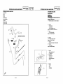
IA-21
NOTICE
This manual was written by the MBK INDUSTRIE primarily for use by YAMAHA dealers and their
qualified mechanics. It is not possible to put an entire mechanic's education into one manual, so it is
assumed that persons using this book to perform maintenance and repairs on YAMAHA scooters
have a basic understanding of the mechanical concepts and procedures inherent in scooter repair
technology. Without such knowledge, attempted repairs or service to this model may render it unfit to
use and/or unsafe.
MBK INDUSTRIE is continually striving to improve all models manufactured. Modifications and significant changes in specifications or procedures will be forwarded to allAuthorized YAMAHA dealers
and will, where applicable, appear in future editions of this manual.
DOCUMENTATION TECHNIQUE
MBK INDUSTRIE
PARTICULARLY
IMPORTANT
INFORMATION
This material is distinguished by the following notation:
/_
The safetyAlert Symbol meansATTENTION! BECOMEALERT! YOUR
SAFETY IS INVOLVED!
r. IIY/-'1:I_11_[¢]1
Failure to follow WARNING instructions could result in severe injury or
death to the scooter operator, a bystander, or a person inspecting or
repairing the scooter.
CAUT}ONi:
NOTE:
CW50
SERVICE MANUAL
© 1997 by MBK INDUSTRIE
3st Edition, April 1997
All rights reserved. Any
reprinting
or unauthorized
use
without the written
)ermission of MBK INDUSTRIE
is expressly
prohibited.
A CAUTION indicates special precautions that must be taken to avoid
damage to the scooter.
A NOTE provides key information to make procedures easier or clearer.
IA-31
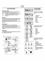
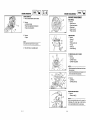
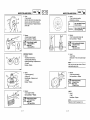
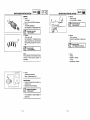
HOW TO USE THIS MANUAL
®
®
ILLUSTRATEDSYMBOLS
(_
L_
Illustrated symbols _ to _ are designed as
thumb tabs to indicate the chapter's number and
CONSTRUCTION OF THIS MANUAL
This manual consists of chapters for the main categories of subjects. (See <<illustratedsymbols).
1st title
(_) This is a chapter with its symbol on the upper right of each page.
2nd
tiUe
3rd title
Q
_)
the chapter (<Periodic inspection and adjustment)) the 3rd title appears.)
This
This tiUeappears
is a final title.on the upper of each page on the left of the chapter symbol. (For
MANUAL FORMAT
I_
I=-I
I
_
_
tion has been compiled to provide the mechanic with an easy to read, handy reference that contains
comprehensive explanations of all disassembly, repair, assembly, and inspections.
A set of particularly important procedure (_)is placed between a line of asterisks "* "with each step
_
content.
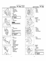
_ General information
z(t_Specifications
_
_ Periodic inspection and adjustment
®
@ Carburetion
_ Chassis
_ Electrical
II
IMPORTANT
by" FEATUREsPreceded
" ""
• Data and a special tools are framed in a box preceded by a relevant symbol ®.
_
:1
_
alignments mark Q, the others being indicated by an alphabetical letter in a box_),
•A
Ancondition
encircledofnumeral
a faulty component
® indicateswill
a part
precede
name,
an and
arrow
ansymbol
encircled
andalphabetical
the course of
letter
action
data
required
for an
thesymbol
(_).
_)Troubleshooting
Illustrated symbols _ to _ are used to identify
the specifications appearing in the text.
_
@
i
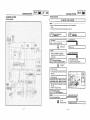
Each chapter provides exploded diagrams are before each disassembly section for ease in identifyEXPLODED DIAGRAM
ing correct disassembly and assembly procedures.
'
_ Filling
fluid
_ Lubricant
i_
@ Tightening
@ Special tool
@ Wear limit, clearance
@ Engine speed
@
<_
OVA
' _.
:_-_.,_.._,';__
.....
:;"--L'..'._,
_
_
_
_
Illustrated symbols _ to @ in the exploded dialubrication point.
gram indicate grade of lubricant and location of
"",_
_-
.-
_';"
.............
!_ .... _
_
_I
__,_.,
®_----
_--_1'¢_
r/,_,
@ I
--i
:,T_...:.:....C.__,_I_:;-_,..,_tF-.-"'_
":_""';_"I
j _| [ E,;2_;c_E
_--
-_-_,
_
__--:5:
_:_'_ ......
:_"':'_-
_
_1___
_
J
_
_
--|
_
_
,
_ Apply engine oil
--_
@ Apply molybdenum
gear oil
_)
disulfide oil
@
_
, Apply lightweight lithium-soap
_ Apply wheel bearing grease
grease
base
@ Apply molybdenum disulfide grease
@Applylockingagent(THREADLOCK®)
@ Use new one
A-4 I
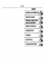
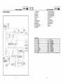
INDEX
SPECIFICATIONS
PERIODIC INSPECTION I _
AND ADJUSTMENT
I '"sP
ENGINEOVERHAUL
CARBURETION
CHASSIS
ELECTRICAL
TROUBLESHOOTING
I
I
I1 II!
[!
1
I GEN
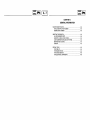
CHAPTER 1.
GENERAL INFORMATION
SCOOTER IDENTIFICATION ....................................................................... A-8
VEHICLE IDENTIFICATION NUMBER ................................................... A-8
ENGINE SERIAL NUMBER .................................................................... A-8
IMPORTANT INFORMATION ......................................................................
ALL REPLACEMENT PARTS ................................................................
GASKETS, OIL SEALS, AND O-RINGS .................................................
LOCK WASHERS/PLATES AND CO'I-I'ER PINS ..................................
BEARINGS AND OIL SEALS ..................................................................
CIRCLIPS ................................................................................................
A-8
A-8
A-8
A-8
A-8
A-9
SPECIAL TOOLS .......................................................................................... A-9
FOR TUNE UP ........................................................................................ A-9
FOR ENGINE SERVICE ......................................................................... A-9
FOR CHASSIS SERVICE ..................................................................... A-10
FOR ELECTRICAL COMPONENTS ..................................................... A-10
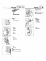
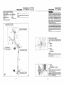
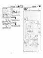
SCOOTER IDENTIFICATION
IGE" I
INFO
A-
8
1
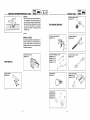
IMPORTANT INFORMATION
INFORMATION
SCOOTER
_
IDENTIFICATION
The vehicle identification numbere is stamped
NOTE:
into the frame,
The vehicle identification number is used to
_
_'-.._
_
_._
__
_O
YAMAHAforassemblyandadjustment.Other
_
brands may be similar in function and appearance, but inferior in quality.
your scooter with the licensing authority in your
state,
VG54RWN0*WA101301
I
Initial serial number:
I
identifyyourscooterand maybe usedto register
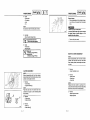
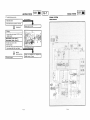
1.All gaskets, seals and O-rings should be replaced when an engine is overhauled. All
gaskets surfaces, oil seal lips and O-rings
2.Properly oil all mating parts and bearing during reassembly. Apply grease to the oil seal
must be cleaned.
lips.
GASKETS, OIL SEALS, AND O-RINGS
_(_
The engine serial number@ is stamped into the
crankcase.
_
PINS
1.All lock washers/plates (_ and cotter pins
must be replaced when they are removed.
Lock tab(s) should be bent along the bolt or nut
flat(s) after the bolt or nut has been properly
tightened.
_
NOTE:
The first three digits of these numbers are for
model identifications; the remaining digits are
the unit production number.
I
INFO
ALL REPLACEMENT PARTS
1. Use only genuine parts for all replacements.
Useoil and/or grease recommended by MBK/
VEHICLE IDENTIFICATION NUMBER
_
I°E"
_
_MHr,IH'
4UY-200101
Initial serial
number:
1. Install the bearing(s) (_ and oil seal(s) ® with
their manufacturer's marks or numbers facing
NOTE:
outward. (In other words, the stamped letters
Designs and specifications are subjectto change
without notice,
must be on the side exposed to view.) When
installing oil seal(s), apply a light coating of
lightweight lithium base grease to the seal
lip(s). Oil the bearings liberally when installing.
BEARINGS AND OIL SEALS
O_
CAUTION: _
__
bearings dry. This causes damage to the
bearing surfaces.
Do not use compressedair to spin the
1 -1
1 -2
IMPORTANT
INFORMATION/SPECIAL
I°E"
_ I
INFO
TOOLS
A"
9
J
SPECIAL
CIRCLIPS
c_) [_
TOOLS
IGE"I
INFO
Flywheel magneto puller
care,u,, 08
e- 0-
clips once
they have
been removed.
Replace
fore
reassembly.
Always
replace piston
pin
bent circlips. When installing a circlip _) make
sure that the sharp edge _ is positioned
opposite to the thrust L_ it receives. See the
sectional view.
Shaft
SPECIAL
FOR ENGINE SERVICE
Crankcase separating tool
90890-01135
TOOLS
Flywheel holding tool
90890_0t_'_
f{_
plete and accurate tune-up and assembly. Using the correct special tool will help prevent
damage caused by the use of improper tools or
improvised
techniques.
The proper special tools are necessary for com-
Inductive tachometer
]
_ _
(_
Crankshaft installing tool set
Clutch serving nut
wrenc_
90890-01277 (_)
FOR
TUNE
UP
._
90890-01411 (_
__
90890-03113
1
\_';_:i"
90890-01275 _)
90890-01274 _)
;_'#--'_
Ignition checker
Sheave
g0890_0_4
_
go8go.01_01
90890-01348
holder
Clutch spring holderri a
1-3
c-_
00890_01010®g°890°1_
Oil Seal Guide
90890-01409 (D
Oil Seal Driver
f_
_/
1-4
SPECIAL
GEN
I 'NFO
TOOLS
I
_1_1
Ring nut wrench
90890-01268 _
90890-01403 _)
,_
FOR CHASSIS SERVICE
Damper rod holder
90890o01294
T-Handle
90890-01326
Oil seal guide
90890-01184
Oil seal guide adapter
90890-01186
Pocket Tester
FOR
COMPONENT
ELECTRICAL
90890-03112
1-5
_
_
IA- _ol
II.FO_1
{J
Ill
-/___/
IsPEc
_'1tA-131
IsPEc
_1
CHAPTER 2.
SPECIFICATIONS
GENERAL SPECIFICATIONS .................................................................... A-14
MAINTENANCE SPECIFICATIONS ........................................................... A-15
ENGINE ................................................................................................ A-15
CHASSIS .............................................................................................. A-16
ELECTRICAL .......................................................................................... B-1
CABLE ROUTING .........................................................................................
B-2
GENERAL
SPECIFICATIONS
I SPEc
/'(_'1
IA-41
GENERAL
SPECIFICATIONS
SPECIFICATIONS
Model
GENERAL SPECIFICATIONS
CW50
Clutch type:
Transmission:
Model
Dimensions:
Overall length
Overall width
Overall height
Seat height
Wheelbase
Minimum ground clearance
CW50
1,740 mm (68.5 in)
665 mm (26.2 in)
1,050 mm (41.3 in)
745 mm (29.3 in)
1,170 mm (46.0 in)
125 mm (4.9 in)
Basic
weight:
With oil and full fuel tank
78 kg (172 Ib)
Minimum
turningradius:
1,800mm(70.9in)
Engine:
Type
Cylinder arrangement
Displacement
Bore x stroke
Air-cooled 2-stroke, gasoline torque induction.
Single cylinder, Vertical
49 cm3
40 x 39.2 mm (1.57 x 1.54 in)
Compression ratio
Starting system
Lubricationsystem:
7.01 : 1
Electric and kick starter
Separatelubrication (Yamaha Autolube )
Oil type or grade:
Engine oil
Semi-synthetic oil in accordance to the
API TC TS C3 standard.
SAE 10W30 type SE motor oil
Transmission oil
Oil capacity:
Engine oil:
Total amount
1.3 L (1.14 Imp qt, 1.37 US qt)
Transmission oil:
Periodic oil change
Total amount
Airfilter:
Fuel:
Type
Tank
capacity
Carburetor:
0.11 L (0.10 Impqt, 0.12 US qt)
0.13 L (0.11 Impqt, 0.13 US qt)
Wettypeelement
Regular unleaded gazoline (RON 91 mini)
4.6L(1.01Impgal,1.21USgal)
Type
Manufacturer
PHBN12HS
DELL'ORTO
Spark plug:
I SPEC
Dry, centrifugal automatic
Primary reduction system
Primary reduction ratio
Secondary reduction system
Secondary reduction ratio
Transmission
Operation
Chassis:
Frame type
Helical gear
52/13 (4.000)
Spur gear
43/13 (3.3077)
V-belt
Automatic
Steel tube underbone
Caster
angle
Trail
27
°
90 mm (3.54 in)
Tire:
Type
Size
Manufacturer
Tubeless
120/90 - 10
130/90 -10
DUNLOP (TRAIL MAX)
MICHELIN (REGGAE TL)
front
rear
front
rear
DUNLOP (TRAIL MAX)
MICHELIN (REGGAE TL)
Tire pressure (cold tire):
Maximumload-exceptscooter
Up to 90 kg (198 Ibs) load
152 kg (335Ibs)
Front
Rear
100 kPa (1.00 kgf/cm2, 15 psi)
125 kPa (1.25 kgf/cm2, 18 psi)
Front
Rear
100 kPa (1.00 kgf/cm2, 15 psi)
150 kPa (1.50 kgf/cm2, 21 psi)
90 kg (198 Ibs) ~ maximum load
Brake:
Front brake type
Operation
Rear brake type
Operation
Suspension:
Front
Rear
Shock
absorber:
Disc brake
Right hand operation
Drum brake
Lefthand
operation
Telescopic fork
Unitswing
Front
Rear
Coil spring/Oil damper
Coil spring/Oil damper
!Wheel travel:
Type/Manufacturer
Gap
BR8HS/NGK
0.5 - 0.7 mm (0.020 ~ 0.028 in)
2-1
Front wheel travel
Rear wheel travel
62 mm (2.44 in)
60 mm (2.36 in)
2-2
/(_i'
I P'=c
Model
CW50
Electrical:
MAINTENANCE SPECIFICATIONS
I SPEc
/'_'1
MAINTENANCESPECIFICATIONS
ENGINE
Ignition
system
Charging system
Battery type/model
Battery capacity
CDI
Flywheel magneto
GM4-3B/YB4L-B/FB4L-B
12V 4AH
Headlight type:
Bulb wattage / quantity:
Taillight/brake light
Flasher light
IA-lSI
Model
Cylinder head:
Warp limit
Bulb
12V 5W/21 W x 1
12V 10W x 2
Front
Rear
12V 10W x 2
12V 3W x 1
Meter light
Warning lights wattage / quantity:
"OIL"
"TURN"
12V 3W x 1
12V 3W x 1
"HIGH BEAM"
12V 3W x 1
CW50
0.03 mm (0.0012 in)
* Lines indicate straight edge measurements.
,k
__
-_'_
_'_
Cylinder:
Bore size
<Limit>
Taper limit
Piston:
MeasuringPiSt°n
size point .
39.993 - 40.012 mm (1.574 ~ 1.575 in)
<40.1 mm (1.579 in)>
0.006 mm (0.0002 in)
_
_¢'
39.952 - 39.9725.0
mmmm(0.2(1.573in)
~ 1.574 in)
Piston clearance
<Limit>
Piston pin bore size
0.034 ~ 0.047 mm (0.0013 - 0.0018 in)
<0.1 mm (0.004 in)>
10,004 ~ 10.015 mm (0.3938 - 0.3943 in)
Piston pin:
Outside diameter
Piston
Top ring
Sectional sketch (B x T)/Type: L_j_
2ndring
- T
End gap (installed):
Top ring
2nd ring
Side clearance (installed):
Top ring
2nd ring
2-3
9.996 ~ 10.000 mm (0.3935 ~ 0.3937 in)
ring:
1.2 ~ 1.8 mm (0.047 ~ 0.070 in)
B
-
1.2 -1.8 mm (0.047~ 0.070 in)
0.15 ~ 0.30 mm (0.006 - 0.012 in)
0.15 ~ 0.30 mm (0.006 ~ 0.012 in)
0.03 - 0.05 mm (0.0012 - 0.0020 in)
0.03 - 0.05 mm (0.0012 ~ 0.0020 in)
2-4
MAINTENANCE
SPECIFICATIONS
Model
IsPECIA-161
CW50
MAINTENANCE
SPECIFICATIONS
CHASSIS
Crankshaft:
Model
EB__:J
Crank width "A"
37.90 - 37.95 mm (1.492 - 1.494 in)
Runout limit "C"
Connecting rod big end side clearance "D"
i Automatic centrifugal clutch:
Shoe thickness
<Wear limit>
Clutch shoe spring free length
Clutch-in revolution
0.03 mm (0.0012 in)
0.2 - 0.5 mm (0.008 - 0.020 in)
4.0 mm (0.16 in)
<2.5 mm (0.10 in)>
26.2 mm (1.03 in)
3.200 ~ 3.600 r.p.m.
CW50
Steeringbearingtype
No/Size of steel balls:
Steering system:
Upper
Lower
Ballbearing
22 pcs (3/16 in)
22 pcs (3/16 in)
Front suspension:
Front fork travel
Spring Rate (K1)
Stroke (K1)
Spring Rate (K2)
Stroke (K2)
Optional spring
70 mm (2.75 in)
10.8 N/ram (1.08 kg/mm, 60.46 Ib/in)
0 ~ 40 mm (0 ~ 1.57 in)
14.4 N/ram (1.44 kg/mm, 80.61 Ib/mm)
40 ~ 77 mm (1.57 in ~ 3.03 in)
No
Clutch-stall revolution
V-belt:
Width
<Wear
limit>
Transmission:
6.300 - 6.900 r.p.m.
Main axle runout limit
Drive
axlerunout
limit
Kick starter:
0.08 mm (0.003 in)
0.08mm(0.003
in)
Stroke
Optional
spring
Wheels:
0 ~ 44 mm (0 ~ 1.73 in)
No
Ratchet type
150 ~ 250 g (5.3 - 8.8 oz)
Front wheel type
Rear wheel type
Front wheel size
Material
Cast wheel
Cast wheel
MT 3.50 xl0
Aluminium
15 mm (0.59 in)
<13.5mm(0.53in)>
Type
Kick clip tension
Carburetor:
I.D. mark
PHBN12HS
Main jet
(M.J.)
Main air jet
(M.A.J.)
Jet needle
(J.N.)
Needle jet
(N.J.)
Cutaway
(C.A.)
Pilot jet
(P.J.)
Bypass
(B. P.1)
Pilot air screw
(A.S.)
Valve seat size
(V.S.)
Starter jet
(G.S.1)
Float height
(F.H.)
Fuel height
(F.L.)
(Center of float chamber / Fuel height)
Engine
idlespeed
# 93
2.0
A21-3/5
2.110
4.0
# 36
0.8
1-5/8 _+114out
1.2
# 40
15 - 17 mm (0.59 ~ 0.67 in)
20.5 ~ 22.5 mm (0.80 ~ 0.88 in)
1800_+
200rpm
Reed
valve:
Valve stopper height
Reed valve clearance
4.0 ~ 4.4 mm (0.157 ~ 0.173 in)
0.2 mm (0.008 in)
Lubrication system:
Stroke
Bore
Autolube pump
2.62 mm (0.10 in)
0.5 mm (0.02 in)
Rear suspension:
Shock absorber travel
Spring free length
Springfittinglength
Spring Rate
60 mm (2.36 in)
202 mm (7.95 in)
187.5mm(7.38in)
32.5 N/ram (3.25 kg/mm, 181.93 Ib/mm)
Front wheel size
Material
Rim runout limit:
Front
Rear
Front disk brake:
Type
Diameter & thickness
Pad thickness
<Wear limit>
Master cylinder inside diameter
Caliper cylinder inside diameter
Brake fluid type
Reardrumbrake:
MT 3.50 xl0
Aluminium
2.0 mm (0.08 in)
2.0 mm (0.08 in)
Single disk
155 x 3.5 mm (6.102 x 0.137 in)
3.25 mm (0.127 in)
<0.8 mm (0.03 in)>
11 mm (0.43 in)
30 mm (1.18 in)
DOT #3 or DOT #4
Type
Drum inside diameter
<Wear limit>
Leading,
trailing
110 mm (4.33 in)
<110.5 mm (4.35 in)>
Lining thickness
<Wear limit>
Spring free length
4.0 mm (0.16 in)
<2.0 mm (0.08 in)>
54 mm (2.125 in)
Front brake lever freeplay:
Rear brake lever freeplay:
2-5
10 ~ 20 mm (0.4 ~ 0.8 in)
10 ~ 20 mm (0.4 - 0.8 in)
2-6
M.,.TE.A.OE.PEC,..C..,O.S
Is Ec B-1I
M.,.TE...CES.EC,F,C
ISPEC
ELECTRICAL
Model
Model
CW50
Voltage:
12 V
Ignition system:
Ignition timing (B.T.D.C.)
CDI:
Pickup coil resistance (color)
Source coil resistance (color)
Ignition coil:
Minimum spark length
Primary coil resistance
Secondary coil resistance
14° at 5.000 r/rain
400 ~ 600 Q at 20°C (68°F) (White/Red-Black)
640 ~ 960 Q at 20°C (68°F) (Black/Red-Black)
6 mm (0.23 in)
0.56 ~ 0.84 Q at 20°C (68°F)
5.68 - 8.52 Qk at 20°C (68°F)
Spark plug cap:
Resistance
CDI Magneto:
Lighting coil resistance
Lighting coil resistance
Voltage regulator/Rectifier:
Type
5 k.Qat 20°C (68°F)
0.32 ~ 0.48 Q at 20°C (68°F)(Yellow/Red-Black)
0.48 ~ 0.72 Q at 20°C (68°F)(White-Black)
Semi-conductor, short-circuit type
No load regulated voltage
Capacity
Withstand voltage
13 ~ 14 V
8A
600 V
Capacity
12V, 4 Ah
Specific gravity
Starter motor:
Output
Armature coil resistance
Brush length
<Wear limit>
Brush spring pressure
Commutator diameter
<Wear limit>
Mica undercut
1.280
0.14 kW
0.072 _ a 20°C (68°F)
6.8 mm (0.27 in)
<5.3 mm (0.21 in)>
150 - 650 gr (5.29 ~ 22.92 oz)
15.8 mm (0.62 in)
<15.0 mm (0.60 in)>
1.15 mm (0.045 in)
Starter relay:
Amperage rating
Coil resistance
20 A
54 - 66 _ at 20°C (68°F)
Horn:
Type/Quantity
Model/Manufacturer
Maximum amperage
Plain type/1 pc.
TR9/FRANSVAL
2.5 A
Flasher relay:
Type
Self cancelling device
Flasher frequency
Wattage
Circuit breaker:
Type
Amperage for individual circuit x Quantity:
Main
Fuel sender unit:
Resistance
2-7
CW50
Battery:
Condenser type
No
70 - 90 cycle/rain
2 x 10W + 4 W
Fuse
7Ax1
(full)
(empty)
4 - 10 _ at 20°C (68°F)
90 - 100 _ at 20°C (68°F)
2-8
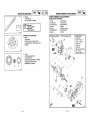
CA..E.OUT,.O
IS" clPI
IB'2
_3) Rim
_) Tire
® Brake disc
Brake caliper
_) Brake hose guide (Lower)
® Brake hose guide (Upper)
Throttle cable
® Wire harness
Speedometer cable
Brake hose
_) Choke cable
[]
[]
[]
[]
[]
Do not cover the frame number.
Attach the brake hose, starter switch cable and the brake cable
together behind the horn bracket.
The throttle cable must have sufficient free play.
Clamp the brake hose into the upper holder.
With a band tie the choke cable, the throotle cable and the rear
brake cable to the left side, the wire harness to the right side of
the frame.
@ Rear brake cable
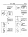
CA°LE.O°T,.O
IS"EclP
_)
_)
®
_)
_
_)
_)
®
(9)
_
Handlebar
Left handle bar switch
Right handlebar switch
Handlebar wire harness holder
Flasher relay
Speedometer cable
Throttle cable
Lower handlebar cover
Front brake hose
Flasher ground
[]
[]
[]
[]
[]
[]
[]
[]
[]
o
The right handlebar switch leads must pass along the underside
of the handlebar, then behind the boss on the lower handlebar
cover.
Pass the couplers behind the speedometer cable, and after
connecting them, fit them under the right side of the
speedometer.
The left handlebar switch leads must pass along the underside of
the handlebar, then in front of the boss on the lower handlebar
cover.
Attach the front flasher ground to the handlebar.
The throttle cable must pass in front of the handlebar.
Pass the flasher relay leads under the handlebar.
The brake light leads must pass along the underside of the
handlebar (left and right).
The wire harness holder must pass over the handlebar.
The brake hose union bolt must touch the right side of the boss.
I
%
[]
2-9
2-10
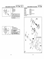
OASLERO°T,
NO
ISPECl;]
IB'3
(_)
(_)
®
(_
Choke cable
Throttle cable
Rear brake cable
Speedometer cable
®
(_
(_)
®
®
Front brake hose
Main switch
Wire harness
Horn
Steedng tube
Lower cover
[]
[]
[]
[]
[]
[]
[]
[]
[]
[]
[]
[]
Tie the choke cable,throttle cable, rear brake cable, and speedometer
cable to the left side of the handlebar.
Pass the wire harness along the right side of the handlebar.
Clamp the front brake hose to the lower cover.
The speedometer cable must pass belween the steering tube and the
main switch bracket.
Attach the wire harness to the side of the main switch bracket with a band.
The wire harness must run straight (no loops)between the two bands.
Attach the wire hamess with a band to the steedng tube just above the
wire bracket.
The speedometer cable must pass through the hole in the front fender.
The speedometer cable must pass through the hole in the lower fender.
The horn leads must pass behind the horn bracket and behind the wire
bracket.
The front brake hose must pass through the wire bracket.
The front brake hosde must pass through the hole in the fender.
T
II
2-11
=
.....
Is'c
I INSP
BEI
-
I
I
CHAPTER 3.
PERIODIC INSPECTION AND ADJUSTMENT
INTRODUCTION ...........................................................................................
B-7
PERIODIC MAINTENANCE/LUBRICATION INTERVALS ........................... B-7
COVERS .......................................................................................................
REMOVAL ...............................................................................................
INSTALLATION .......................................................................................
B-7
B-7
B-8
ENGINE ........................................................................................................ B-9
ENGINE IDLE SPEED ADJUSTMENT ................................................... B-9
THROTTLE CABLE FREE PLAY ADJUSTMENT .................................. B-9
SPARK PLUG INSPECTION ................................................................ B-10
AUTOLUBE PUMP AIR BLEEDING ..................................................... B-10
ENGINE OIL LEVEL INSPECTION ...................................................... B-11
TRANSMISSION OIL REPLACEMENT ................................................ B-11
AIR CLEANER ELEMENT CLEANING ................................................. B-12
CHASSIS ....................................................................................................
FRONT BRAKE LEVER FREE PLAY ADJUSTMENT ..........................
REAR BRAKE LEVER FREE PLAY ADJUSTMENT ............................
BRAKE PADS INSPECTION ................................................................
BRAKE SHOES INSPECTION .............................................................
AIR BLEEDING (HYDRAULIC BRAKE SYSTEM) ................................
STEERING HEAD ADJUSTMENT ........................................................
TIRE INSPECTION
...............................................................................
WHEEL
INSPECTION
..........................................................................
CABLE INSPECTION
AND LUBRICATION
..........................................
LEVER
LUBRICATION
.........................................................................
CENTERSTAND
LUBRICATION
..........................................................
REAR SHOCK
ABSORBER
.................................................................
B-12
B-12
B-12
B-12
B-13
B-13
B-14
S-14
B-15
B-15
B-15
B-15
B-15
ELECTRICAL
..............................................................................................
BATTERY
INSPECTION
.......................................................................
FUSE INSPECTION
..............................................................................
HEADLIGHT
BEAM ADJUSTMENT
.......................................................
B-16
B-16
B-16
C-1
LUBRICATION
INTERVALS
INTRODUCTIONIPERIOOIC
MAINTENANCEI
PERIODIC
INSPECTION
I ADJ
INSP
IF_
I
I
B-
7
COVERS
AND ADJUSTMENT
_ I __
i_ d
information applies to vehicles already in service as well as new vehicles that are being prepared for
sale. All service technicians should be familiar with this entire chapter.
,/___I_
ITEM
PERIODIC
BREAK-IN
1,000(600)
ROUTINE
Check condition.
O
Replace if necessary.
Check idle speed/choke operation.
Adjust
if necessary.
Clean.Clean
if necessary.
Check or
fuelreplace
hose and
vacuum pipe for cracks or
damage.
O
MAINTENANCE/LUBRICATION
2
Air filter
3
1
4
Carburetor
Spark plug
Fuel
line
-!
_ _
©
O
O
O
O
O
O
©
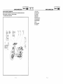
1. Remove:
• Seat C)
REMOVAL
__
_
Unit : Km(miles)
EVERY
3,000
8.000
(2,000)or
(4,000)or
8 months
12 months
©
i Transmission
oll
Autolube pump
7
Front brake system
Check
operation/fluid
leakage/See NOTE. (Page 9-3).
Correct
if necessary.
Check for
oil leakage,
8
Rear brake system
Check ifoperation,
Adjust
necessary.
9
Wheels
Check damage/runout/tightening
Replace/tighten if necessary.
1(
Wheel bearings
Check bearing assembly for looseness/damage.
11
Steering bearing
Check bearing assembly for looseness.
Correct if necessary.
Moderately repack every 12,000 (8,000) or 24 months.**
REPLACE
©
O
torque.
©
_
light
leads
_J
• Rear carrier C)
2. Disconnect:
_!_::=_
-_
_
_
• Washer
•
Rear shock absorber
Check
Replaceoperation/oil
if necessary.leakage,
1,'.
V-belt
Check damage and wear.
Replace if necessary.
IL
Fitting/Fasteners
Check all chassis fittings and fasteners.
33ghtan if necessary,
©
1,=
Centerstand
Repair if necessary.
O
Battery
Check
gravity,
Replacespecific
Check
operation.
if damaged,
Check breather pipe for proper operation.
Correct if necessary.
Central cover (_
O
O
O
O
O
O
©
O
©
__
6.
1".
O
o
• Front cover
Disconnect:
(D
• Headlight leads
O
O
©
O
©
©
O
O
O
e_.
_
_
5. Remove:
--
7. Remove:
• Main switch cover (D
Items marked with an asterisk I I require special tools, data and technical skills for servicing.
Take the scooter to a Yamaha Dealer or refer to the Service Manual when servicing these items.
•*
leads
• Flasher
4. Remove:
Correct if necessary.
Replace every 12,000 (8,000) or 24 months.
(Warm engine before draining.)
Check operation.
Correct if necessary.
Bleed the air.
6
1(
• Taillight
3. Remove:
Replace if necessary,
S
I
.Helmet holder (_)
I
i_<_
(___
operation and a longer service life. The need for cosUy overhaul work will be greaUy reduced. This
_
COVERS
,
ments.
Theseincludes
preventive
maintenance
procedures,
if followed,
will ensureinspections
more reliable
This chapter
all information
necessary
to perform
recommended
and vehicle
adjustINTRODUCTION
I_
INSP
: Medium weight wheel bearing grease.
NOTE:
Turn the main switch cover counterclockwise
and pull it out.
_
NOTE:
Brake fluid replacement:
1. When disassembling the master cylinder or caliper cylinder, replace the brake fluid. Normally
check the brake fluid level and add fluid as required.
2. On the inner parts of the master cylinder and caliper cylinder, replace the oil seals every two years.
3. Replace the brake hoses every four years, or when cracked or damaged.
3-1
_
• Front panel (_
3-2
COVERS
,
:__
_
B-8
I
COVERS I INSP_ _1
• Footrest board (D
• Bottom cover (_)
.
t_
I INSP
_
_ffr_ I
• Front panel (D
• Main switch cover (_)
_
_
_
NOTE:
Insert the main switch cover and turn it clockwise.
8. Remove:
• Screws (Handlebar cover) (D
eove
Insert the projections of the front panel into the
4. Install:
slot
of the footrest board.
NOTE:
___
: ::_'
;
• Headlight leads
Conn
• Speedometer cable (_)
• Couplers
6. Install:
• Front
fender
0
11.
Remove:
NOTE:
o Handlebar cover (Upper) (_)
10.
Disconnect :
INSTALLATION:
Reverse the "REMOVAL" procedure. Note
the following points.
1. Connect:
o Speedometer cable
• Couplers
/
Correct routing of cables and wires is essential
NOTE:
for
a safe operation of this scooter. Refer to
Insert the projection "a" of side cover into the slot
"b" of footrest board.
f
7. Install:
• Central coverO
[l_'_:_"_
_
_
NOTE:
Insert the projection "a" of central cover into the
slot "b" of footrest board.
_(D
• Rear carrier (D
• Handlebar cover
NOTE:
2."CABLEInstaIt:ROUTING"
in Chapter 2.
Be careful not to pinch any wires with the covers.
_
___"_
• Seat
"\_
__
NOTE:
8. Install:
After con necting the tail and flasher light lead,
I'1
locate
• Helmet
the couplers
holder inside the rear fender.
• Bottom cover (_)
• Footrest board (_)
'
15.5 Nm (1.55 m.kg, tl.21 ff.lb)
Nut (Seat):
8 Nm (0.8 rn.kg, 5.8 ft.lb)
NOTE:
_
_
_
__
_
17 (Rear
Nm (1.7
m.kg, 12.3 ft.lb)
carrier):
Mesh the projections of footrest board and bot-
NOTE:
tom cover.
When installing the covers, be careful not to
damage
the mounting
clips.
- Nut
(Rear carrier):
3. Install:
3-3
3-4
ENGINE
ij
IDLE
SPEED
j
__
I'"sP II
ADJUSTMENT
_
_
B
- 9
THROTTLE
CABLE
FREE
PLAY
I'"sP I
ADJUSTMENT
_
1. Tighten:
• Pilot air screw O
Turn the pilot air screw in until lightly seated.
1. Check:
-Throttle cable free play @
Out of specification ---*Adjust.
2. Loosen:
o Pilot air screw
ENGINE
IDLE
SPEED
ADJUSTMENT
Back out
from
the lightly
seated position.
MENT
.-.:=::::::==::::=_xx=_==:_x-,=:=:=__
~ 3.0@:
mm (0.06 ~ 0.12 in)
--_Free 1.5play
Throttle cable free play adjustment steps:
1-518turns
-+114
f_ Pilot
air screwout
position:
NOTE:
I
Before adjusting the throttle cable free play, the
engine idle speed should be adjusted.
3. Start the engine and let itwarm up for several
minutes.
V!IW_,I;1 _11_
[¢]I
First step:
Loosen the Iocknut (_) on the throttle cable.
• Turn the adjuster (_) in or out until the specifled free play is obtained.
For safety reasons, place the scooter on
the center stand before starting the engine,
4, Attach:
• Inductive tachometer
(to the spark plug lead)
I
'ndu°t'vetac'°meter:
.ef:..0.03t
1,
Turn in
Free play increased.
Turn out
Free play decreased.
T0 tent,e
_WARNING
After adjusting, turn the handlebar to the
right and left, making sure that the engine
idling speed does not change.
5. Check:
• Engine idle speed
Out of specification -) Adjust.
1800 + 200 rlmin
6. Adjust:
• Engine
::::::::":::::::==::":::::::=::*_**_::::::::::*"*"*
I
idle speed
Turn the throttle stop screw O in or out until
specified idling
speed is obtained.
Adjustment
steps:
__
Turning
left
Turning right
3-5
Idling
speed increased.
Idling speed decreased.
3-6
I
SPARK
PLUG
INSPECTION
INSP
IB-101
I
I
SPARK PLUG INSPECTION
/_
• Spark plug
2. Check:
• Spark plug type
Incorrect _ Replace
;_
,i,/_
_,_'_-_H_'/I_
'
1. Remove:
_
i
I
BR8HS (NGK)
.4
AUTOLUBE PUMP AIR BLEEDING
" Fan cover (_
_
_,
1, Remove:
'_ ....
2. Bleed:
Wear/Damage _ Replace.
@
*......................................................
•. Insulator
Electrode(_)
O
Abnormal color _ Replace.
___
-_ //_-_(,_.=_E_i
Normal color is a medium-to-light tan color,
__/_i_
'_
3. Inspect:
Plug gap @
4. •Measure:
Out of specification .-, Adjust gap.
'/___
Use a wire gauge or feeler gauge.
I_
_
ll\ \
\\_\ _
""'
\\_
'
'\ \\-
i__
Pump bleeding steps:
Place a rag under the pump.
°
Remove
bleed
Let
oil runthe
until
therescrew
are no(_.
more air bubbles
•
• Pump housing and oil hose
When
init. there are no more bubbles, tighten the
bleed screw.
NOTE:
0.5 ~plug
0.7 mm
~ 0.028 in)
Spark
gap (0.020
@:
If
it is damaged,
replace
it with
new one.
Check
the condition
of the
bleeda screw
gasket.
5. Tighten:
• Spark plug
NOTE:
Before installing the spark plug, clean the gasket
surface and plug surface.
Start
theengine.
Let the engine run two or three minutes at
2000 rpm. This will force out any air in the
hose.
........ , .................
******.............
, .........
NOTE:
First tighten
tion.
I_
3-7
by hand,
then torque
to specifica-
20 Nm
(2.0 m.kg, 14ft.lb)
Spark
plug:
I
3-8
ENGINE OIL LEVEL INSPECTION
B - 11
I
TRANSMISSION OIL REPLACEMENT
ENGINE OIL LEVEL INSPECTION
_
II
II
30
20_'?_-
t __"_"
_
• Oil level
Oillevellow --Add oiltoproperlevelas
_
8o
,= ,_-_l
_-- _
_'_'°°El_-_
_e_
_'_'_h,40
50 60 70
.(_
,,
II
__!_//:
O "OIL" indicator light
I
to.
Drain the transmission oil.
•"Oil
Gasket
filler (drain
plug_ plug)
2. Check:
• O-ring (oil filler plug)
Damaged _ Replace.
/
_
_,
T
3. Install:
,_,_
-Gas ket(_
Drain plug:
•Drain
plug
(_)
17.5 Nm (1.75 m.kg, 12.6 ft.lb)
_
_
light.
"OIL"indicator
4. Fill:
,r--m,.,on
o.
to "ON".
SAE 10W30 type SE motor oil
I
Periodic replacement
0.11 L (0.10 Imp qt, 0.12 US qt)
_
I
Inspect
FaulW
Light
bulb
etc.
and electric circuit
I"OIL" indicatorgoes_
Engine
are oil
OK.level
t
_
stays on.
I
i
_
'
NOTE:
"OIL" indicator
Add_ oil.
I
Wipe off any oil spilt on the crankcase, tire or
Total amount
wheel.
J
I "OlL'indicstor
J
Capacity:
0.13 L (0.11 Imp qt. 0.13 US qt)
5 Install:
stays on.
• Oil filler plug
.°..n,..,co.,n.ccor°-to theAPITCTSC3standard.
Capacity :
Total:
t.3 L (1.14 Imp qt, 1.37 US qt)
Install the oil tank filler cap (_ and push it fully
into the filler.
NOTE:
Always use the same type of engine oil;
mixing oils may result in a harmful chemical
reaction and lead to poor performance.
3-9
I
° Transmission case
IT°rn
a'n
switch
electrical circuit,
_
• Drain plug @
_J""
"_-,,"_
_
TRANSMISSION OIL REPLACEMENT
'
Turn
main
switch
doesn't
light,
"OIL"
indicator
" ' __
_ -_)
'i
follows.
OIL LEVEL AND GAUGE CHECK
I
_
I'"sPI
3-10
FRONT BRAKE LEVER FREE PLAYADJUSTMENT/
AIR FILTER ELEMENT CLEANING
-J-_
z
I
_
_
IIB
- 12
I
BRAKE PAD INSPECTION
AIR FILTER ELEMENT CLEANING
_ _
1. Remove:
: CAU_i0N_::
• Air cleaner case cover (_)
element
removed.
Unfiltered
air will
cause
Never operate
the engine
with the
air cleaner
rapid wear of engine parts and possible
engine damage.
/
/
._
J
_
1. Check:
• Front brake lever free play @
Out of specification _ Adjust.
JUSTMENT
10 play:
~ 20 mm (0.4 ~ 0.8 in)
_
Free
_
A soft or spongy feeling in the brake lever can
indicate the presence of air in the brake
system.
Thisairmustberemoved
bybleeding
the brake system before the scooter Is
operated. Air in the system will reduce brake
performance and can result in loss of control
and an accident. Inspect and bleed the system
::=:::::::::=:::::::::::::::::=::::::=::::==:::::::"_
Cleaning steps:
Wash the element gently but thoroughly in
solvent.
if necessary.
REAR BRAKE LEVER FREE PLAY AD(_)__
JUSTMENT
1. Check:
_l.*liW,_l;l_ll_,[Hll
gasoline to clean the element. Such solvents
may lead to fire or explosion.
__=_
Never use low flashpoint solvents such as
• Squeeze excess solvent out of the element
and let dry.
___
• Rear brake lever free play @
h=,
_
Free play:
10 ~ 20 mm (0.4 ~ 0.8 in)
r'_'xIOutof specification --*Adjust.
.......
........
Do not twist the element ....................................................
,_
=b
Adjustment steps:
Turn the adjuster (_) in or out until the speci-
Sqeeze out the excess oil.
_
_
oil on the element,
NOTE:
I
Front brake lever free play
Apply foam air filter oil or SAE 10W30 typ SE
Q_
I
:CAUTiONi
3. Inspect:
• Element
(T)
• Damage-* replace,
4. Clean:
• Air filter element
r'
I
FRONT BRAKE LEVER FREE PLAY AD-
JJ
//
_r_
CHASSIS
_(_)
2. Remove:
• Air filter element
/
/
_
, ..................................................
_//_
2. Adjust:
fled free play is obtained.
Out of specificatin _ Replace brake pads.
The element should be wet but not dripping.
/_,_
__'__
INSPECTION1..Measure:Brake
BRAKE
PADS
pads @
Replace the brake pads and spring as a set
when replacing the brake pads.
_70o_
3-11
3-12
.OTE
_
Brake pads wear limit:
0.8 mm (0.03 in)
"E'"S"OE''"SPEC"O"'I'"SP
IIB = 13 I
BRAKE
FLUID
//
J
LEVEL
INSPECTION
-A_
R_
AIR
BLEEDING
(HYDRAULIC
BRAKE
1. pp,y
therear
bra e,ever.
Air bleeding steps:
a. Add proper brake fluid into the reservoir.
b. Install the diaphragm. Be careful not to spill
any fluid or allow the reservoir to overflow.
c. Connect a clear plastic tube O tightly to the
.RAKE
S.OE,NSPECT.ON
A,R=EEO..O
BRAKE FLUID LEVEL INSPECTION
NOTE:
/
///
/
_ _I\
'
//_
,
,
caliper bleed screw.
d. Place the other end of the tube into a con-
\
the fluid level, and make sure be turning the
handlebar that the top of the master cylinder is
O
f. Pull the lever as far as possible and hold it
there.
horizontal,
Position the scooter straight up when inspecting
_
\I_
• Brake fluid level
Brake fluid level is under"LOWER" level line
"-* Fill to proper level.
1. (D
Inspect:
_
R
b/j_._ _/
__
i,_l Recommended
brake
flu,d:
CAU_ioNi
"_
-_
_
3,6co_
g. Loosen the bleed screw and pull the lever all
the way.
e. Slowly
apply the brake lever several times.
tainer.the lever is completely pulled, tighten
h. When
the bleed screw, then release the lever.
been removed from the system.
j. Add brake fluid to proper level.
i. Repeat steps (e) to (h) until all air bubbles have
DOT # 3 or DOT # 4
_
bleeding the brake system.
I
******************************************************
Check the operation of the
The brake fluid may corrode painted surfaces
or plastic parts. Always clean up spilled fluid
immediately.
_lvAvL,l ;I _11_
[rll
• Use only the designated
quality
fluid.
Otherwise, the rubber seals may deteriorate
causing leakage and poor brake performance.
• Refill with the same type of fluid. Mixing
fluids may result in a harmful chemical
reaction leading to poor brake performance.
• Be careful that water does no enter the
master cylinder when refilling.
Water will signiflcantly lower the boiling point of the fluid
and may result in vapor lock.
3- 13
A-_
SYSTEM)
1. Bleed:
• Brake fluid.
_=:_="_::_`"_`_`"_`"_"_-`_"_"_"_=_=_=_=_=_=_:_
Indicator reaches the wear limit line (_) .-,
Replace brake shoes,
J [_
I'"sp [
(.YD OL,C
2. Inspect:
• Wear indicator O
I
SYSTEM)
3- 14
brake after
I'"sP I
1. Check:
• Steering assembly bearings
Grasp the bottom of the forks and gently rock
the fork assembly back and forth,
Looseness _ Adjust steering head.
Proper loading of your scooter is Important
for the handling, braking, and other performance and safety characteristics
of your
scooter. Do not carry loosely packed Items
that can shift.
***************************************************
Steering head adjustment steps:
STEERING HEAD ADJUSTMENT
Remove the front fender and the front panel,
Refer to "COVERS" section,
Securely pack your heaviest items close to
the center of the scooter, and distribute the
VT_W_,_I-I_.II_,[¢!
weight evenly from side to side. And check
the condition and pressure of your tires.
,
Makesurethetotalweightofthecargo,
Tighten the nut (D
C)__
/
_._/
I'"sp I
I_=_
Ref : 90890-01268
Ref:90890-01403
Steering
headwrench:
saddlebags, etc. If approved for this model)
doesnot
maximumloadof
the
passenger,exceed
and the
accessories
(fairing,
scooter. Operation of an overloaded
scooter
could cause tire damage, an accident, or
even injury.
NEVER OVERLOAD YOUR SCOOTER.
NOTE:
Tighten the ring nut until no play can be seen.
Unscrew the securing nut
I
_
Install the securing nut
Tighten the securing nut (_
I_
22.5 Nmnut:
(2.25 m.kg, 16.2 ft.lb)
I Securing
rider,
_re pressure(oald)
Upto 90kg
Front
100kPa
Rear
125kPa
90 kg- maximum
100kPa
150kPa
15psi)
18psi)
load*
(1.0Okgflcm_, (1.50kgflcmz,
15psi)
21 psi)
Maximumload:
152kg(335Ib)
'I
NOTE:
Set the torque wrench (_) to the ring nut wrench
SO that they form a right angle.
• Maximumload is the total weightof cargo,rider,pas(1.00kgf/cm=, (1.25kgflcm',
sengerandaccessories.
Move the handlebar up and down, and / or
back and forth. If the handlebar free play is
• Tire surface
torque.
_.'="_i'
Handlebar
securing
bolt:
60 Nm (6.0
m.kg, 43.4
ft.lb)
WearlDamagelCrackslRoad hazards-_ Re,
.
• Wheels
Instal the front panel and front fender.
*****************************************************
excess, tighten the bolt (_)to the specifiedI
//j/_
_'_'___'i'_"
Never attempt even small repairs to the
wheel.
Damage/Bends --_Replace.
2. Inspect:
".//).;
Fv_
TIRE INSPECTION
Ride conservatively
Out of specification _ Adjust,
a tire to
• If the tire is removed with a tire lever, use a
suitable protection to prevent damaging the
rim.
• When installing the tire, make sure the
arrow points to the front.
allow it to seat itself properly on the rim.
1. Measure:.
Air pressure
3-15
after installing
3-16
CABLE
INSPECTION AND LUBRICATION
TIRE INSPECTION/WHEEL
INSPECTION/
I:_
I _
INSP
_
I I B - 15
REAR SHOCK
ABSORBER
CABLE INSPECTION
AND LUBRICATION/
I
• Tire tread depth
Out of specification ._ Replace.
ivuco
Recommended
(front and
Minimum
tire rear):
tread depth
0.8 mm (0.03 in)
I_
I
lubricant:
Engine oil SAE 10W30
CENTERSTAND LUBRICATION
1. Lubricate rotating parts
(D Tread depth
(_) Wear
Side wall
®
indicator
I_=_
Rec°mmended
lubricant:
Engine oil SAE
10W30
WHEEL INSPECTION
1. Inspect:
• Wheels
Damage/Bends _ Replace.
Fv_
Never attempt
even small repairs tothe
wheel.
CABLE INSPECTION AND LUBRICATION
F'==_=_
.___
REAR SHOCK ABSORBER
1. Check:
VIIYL, I-'I_II_.[tt
A damaged cable sheath will rapidly corrode.
As a result, the cable cannot move smoothly
inside the sheath. Since this situation is
immediately.
dangerous,
replace
a damaged
• Rear shock absorber (D
Oil leaks/Damage _ Replace.
2. Check:
• Tightening torque
cable
I
1.
Check:
• Cable sheath
° Cable end
Damage --* Replace.
2. Check:
• Cable movement
Stickness --* Lubricate.
I_
I|
Engine oil SAE lOW30
Recommended
lubricant:
NOTE:
into the sheath.
_._
Hold the cable end up and pour a few drops of oil
3. Lubricate the throttle cable end and the cable
,,:
guide notch
on thesoap
throttle
grip with
grease (D.
Lithium
based
grease
I_:_
Recommended
lubricant:
3-17
I
1. Lubricate rotating parts of the levers
esr
(_
I _
INSP
3-18
31.5 bolt:
Nm (3.t 5 m.kg, 22.8 ft.lb)
Upper
Lower bolt:
17.5 Nm (1.75 m.kg, 12.6 ff.lb)
I
BATTERY
I_ I
t _ _'_ /_)
INSPECTION
UPPER -__
ADJ
_
-
1 6
FUSE INSPECTION
_
BATTERYINSPECTIONI
IINSP
ELECTRICAL
BATI'ERY INSPECTION
LOWER
--
IINSPIIB I
I
:CAgTiONi
• Battery
fluidlevel
it to ensuremaximum
performance.
Fluid level low --_Add to proper level.
Fluid level should be between upper and
lower level marks.
1. Inspect:
_)
Upper level
_IW:I--I_JI_[_
Battery electrolyte is dangerous. It contains
Always
a new
before
sulfuric charge
acid which
is battery
poisonous
andusing
highly
caustic.
Alwaysfollowthesepreventive
measures:
Lower
level
•
Refill with distilled water only. Tap water
contains minerals which are harmful to a
Avoid bodily contact with electrolyte as it
can cause severe burns and permanent
eye injury.
battery.
•
Wear protective eye gear when handling
or working near batteries.
Antidote (EXTERNAL) :
- SKIN- Flush with water.
• EYES - Flush with water for 15 minutes
and get immediate
medical attention.
Antidote (INTERNAL) :
2. Inspect:
• Breather hose
Obstruction _ Remove.
•
3. Inspect:
• Battery
attention.
Batteries generate explosive hydrogen gas.
Always follow these preventive
measures:
Charge batteries in a well-ventilated area.
........................................................
Replace the battery if:
Batteryvoltagewillnotrisetoaspecificvalue
or bubbles fail to rise during charging,
Sulfation of one or more cells occurs. (As
indicated by the plates turning white, or an
accumulation of material in the bottom of the
°
Keep batteries away from fire, sparks, or
open flames (e.g., welding equipment,
lighted cigarettes, etc.)
° DO NOT SMOKE when charging or handling batteries.
KEEP BATTERIES AND ELECTROLYTE OUT
sell.)
Specific gravity readings after a long, slow
charge indicate that one cell is lower than the
rest.
Warpage
evident.
or buckling of plates or insulators
Drink large quantities of water or milk.
Followwith milkof magnesia, beaten egg,
or vegetable oil. Get immediate medical
OFREACH
OFCHILDREN.
is
*******--***--*********************--*********
• Specific gravity
Less than 1.280 .-_ Recharge battery.
_1
i
3- 19
1. Open the seat.
2. Inspect:
• Fuse
0.4 amps/10
hrs
Charging
Current:
Blown --, Replace,
1.280 at 20°C (68 ° F)
Specific Gravity:
3-20
HEADLIGHT
OS'"SPEOT'O"'I'"SP
I
BEAM
ADJUSTMENT
_
_
C
-
1
I'"sp I
I
***************************************************
Fuse replacement
steps:
Turn off the ignition,
• install a new fuse of the right amperage.
• Turn on the switches to verify the operation
of the electric circuit.
if the fuse immediately blows again, check
the electric circuit.
Never use a fuse with a rating higher than
specified. An improper fuse may cause
damage to the electrical circuit, and possibly
cause a fire.
*****************************************************
Main circuit:
1. Adjust:
• Headlight
7A
beam
Higher
Turn out screw O
Lower
Turn In screw (_)
HEADLIGHT
BEAMADJUSTMENT
3 - 21
3 - 22
I
lc-l
CHAPTER 4.
I
ENGINE OVERHAUL
ENGINE
REMOVAL
......................................................................................
COVER
REMOVAL
.................................................................................
CARBURETOR .......................................................................................
CABLES,
LEADS
AND HOSES
..............................................................
ENGINE REMOVAL ................................................................................
C-5
C-5
C-5
C-5
C-6
ENGINE
DISASSEMBLY
..............................................................................
REAR WHEEL ........................................................................................
CENTER
STAND
....................................................................................
CYLINDER
HEAD AND CYLINDER
.......................................................
PISTON
PIN AND PISTON
.....................................................................
KICK STARTER ......................................................................................
PRIMARY SHEAVE ................................................................................
SECONDARY SHEAVE ..........................................................................
STARTER SYSTEM ................................................................................
TRANSMISSION
.....................................................................................
CDI MAGNETO
.......................................................................................
AUTOLUBE
OIL PUMP ...........................................................................
CRANKCASE
AND CRANKSHAFT
........................................................
C-6
C-6
C-6
C-6
C-6
C-7
C-7
C-7
C-8
C-8
C-8
C-9
C-9
INSPECTION AND REPAIR .......................................................................
CYLINDER HEAD .................................................................................
CYLINDER
AND PISTON
.....................................................................
PISTON RINGS ....................................................................................
PISTON PIN AND PISTON PIN BEARING
...........................................
KICK STARTER ....................................................................................
TRANSMISSION
...................................................................................
AUTOLUBE
PUMP
...............................................................................
CRANKSHAFT
......................................................................................
PRIMARY SHEAVE ..............................................................................
SECONDARY
SHEAVE
........................................................................
V-BELT
..................................................................................................
STARTER CLUTCH AND GEARS ........................................................
C-10
C-10
C-10
C-11
C-11
C-12
C-12
C-12
C-12
C-12
C-13
C-13
C-14
ENGINE ASSEMBLY
AND ADJUSTMENT
................................................
CRANKSHAFT
AND CRANKCASE
......................................................
AUTOLUBE
PUMP
...............................................................................
CDI MAGNETO
.....................................................................................
C-14
C-14
C-16
C-16
TRANSMISSION
.....................................................................................
STARTER
SYSTEM
................................................................................
SECONDARY SHEAVE ..........................................................................
PRIMARY
SHEAVE
................................................................................
KICK STARTER
......................................................................................
PISTON PIN AND PISTON .....................................................................
CYLINDER AND CYLINDER HEAD .......................................................
ENGINE
REMOUNTING
.........................................................................
D-I
D-2
D4
D-5
D-6
D-7
D-7
D-8
E.O,.E.EMOV.L
IE"O
''1 IC'I
E.O,.E.EMOV.L
ENGINE REMOVAL
1. Remove:
• Oil hose (_ on oil pump side
COVER REMOVAL
1. Remove:
• Covers
Refer to "COVERS" in CHAPTER 3.
NOTE:
Plug the hose to prevent oil spillage.
ENGINE OVERHAUL
CABLES,
LEADS
ANDHOSES
1. Remove:
• Air cleaner case assembly (_)
CA
RBUR ETOR
• Earth (ground lead)
• Spark plug cap 0
• Starter motor lead (_)
• CDI magneto lead (_)
______,__
• Carburetor cover
_
• Hoses
__
2. Disconnect:
- _._
\
• Rear brake cable (_
%
3. Remove:
• Carburetor (_
• Carburetor top
/_
__
4. Remove:
° Air shroud (_)
• Muffler assembly (_)
(_)
__
° Exhaust protector
o Rear axle nut (_
NOTE:
Apply the rear brake while loosening the rear
axle nut
5. Loosen:
4-1
4-2
_rJ.
1. Place a suitable stand under the frame.
REAR WHEEL
_-_
2, Remove:
1, Remove:
• Left pillion footrest
• Rear shock absorber bolt (lower) (D
. Engine mounting bolt _)
_ .f_(_
_ -_._
• Rear wheel nut
• Rear wheel washer
• Rear wheel
• Brake shoes (_)
• Plate washer (_)
34S001
3. Remove:
j_
_
CENTERSTAND
• Spring (_)
• Clip 0
• Rubber washer (_)
° Axle (_)
• Clamp (_)
• Center stand (_)
1. Remove:
NOTE:
Lift up the frame and remove the engine.
4. Place the frame on a suitable stand.
• Engine
_
358(;O1
1. Remove:
• Air shroud
• Cylinder head C)
- Cylinder head gasket
•
S'
3o_c_s
NOTE:
• Beforeloosening the cylinder head nuts, loosen
the spark plug.
• Loosen the cylinder head nuts crosswise 1/4 of
(_)
_
2.a .°Rem°ve:tUrnCylinder
Cylinder
each before(_gasket
removing(_)
them.
1. Remove:
• Piston pin clip (_
NOTE:
Before removing the piston pin clip, cover the
_, _
cannot accidentally fall into the crankcase.
307OO1
4-3
PISTON
crankcase
PIN
with
AND
a clean
PISTON
rag, so that the clip
4-4
E.O,NEO,..SSE.SLY
IE"O
_'1IC'_]
E.O,NEO,SASS
IE"O
''1
2. Remove:
• Piston (_)
• Piston pin bearing (_)
PRIMARY
SHEAVE
• Fan
2. Remove:
• Nut C) (primary sheave)
:j:
NOTE:
__)(__)
3070O2
Do not use a hammer to drive out the piston
pin.
•Piston pin(_
__
319035
KIGKSTARTER
_--------_
_V
_---J'-"==__(_).._F_
o o-
To loosen the primary sheave nut hold the CDI
magneto with a flywheel holder (_).
1. Remove:
I_
Flywhee190890.01235holder:
I
Kick crank
•• Transmission
cover O (teft)
_-_T_
®
_/_
•
pinion gear (D
• Ratchet (_)
• Washer (_)
• Fixed primary sheave (_)
• Washer
(_
2.
NOTE:
To remove the kick pinion gear, push down the
kick
crank.
3. Unhook:
_
@
• Kick return spring (_)
•cirdi0s_
• Plate washer (_)
• Kick shaft (_)
• V-belt
3,goo,
"_/__
.S0_cer_
° Primary sliding sheave (_)
317O02
SECONDARY SHEAVE
-(_
1. Remove:
Hold the secondary sheave with a sheave holder
(_)to loosen the nut.
c c 319003
c
4-5
4-6
NOTE:'
Nut 0 90890-01701
(secondary sheave)
I_
sheave
h°'der:
I
l..olo,..l
2. Remove:
• Crankcase cover gasket
\
_._"
/_
_/
_
• Dowel pins
3. Attach:
• Sheave holder (_)
2" Remove:
• Nut wrench (41 mm)
• Secondary sheave (_)
_/_
•o,utc,
housing
®
90890-01701
sheave h°lder:
l_
• Starter motor
° Bearing _
_ _______
__
t
_--'--_
___'_L
• Clutch securing nut
- Washer ®
(_
•Spacer
• Transmission case O
TRANSMISSION
1. Remove:
o._
___II
tc_
_,
• Dowel pins
Loosen the nut but do not remove it yet,
_o3
4. Loosen:
__
= Gasket
2 Attach
_
_ _ \
NOTE:
Compressthe secondary sheave using the clutch
spring holder (_.
/_
_ __
_ t;_'
__ _
;_
_
\_._ ....
Main shaft _)
2 -Remove
• Plate washer
Clutch spring holder:
90890-01337
_o_
washer (_)
• Conicalspring
(_)
____,
____(_
_
......
3. Remove:
• Clutch securing nut
• Secondary sheave axle _)
• Clutch assembly (_)
6. Remove:
• Spring seat (_
(_) (_)
•• Guide
Clutch pin
spring
• Secondary sliding sheave (_)
_
• Oil seal (_)
3_,o_
CDI MAGNETO
• Nut O (rotor)
. Plate washer
STARTER SYSTEM
_(_/___---(_)
1. Remove:
• Starter clutch assembly _
_0_/_.
_@0@
(_
NOTE:
•
• Idle gear (_)
Plate (_ (idle gear)
/_
_
• Starter wheel gear (_)
loosen the nut.
Hold the rotor using the flywheel holder (_) t°
32_
_
4-8
4-7
90890-01235
F,ywheel holder:
I
I..o"-.I c-91
?_
L/
• Rotor (_
• Woodruff key
level the tool body.
Use the flywheel puller (_)
3. Remove:
° Crankcase
I
90890-01189
_
32'005
I
_
314001
]
1
I'"° "1
As pressure
is applied,
keepbosses.
tapping carefully
on the engine
mounting
Stator assembly
2. ••Remove:
Gasket
:sary,
CAUTION:
loosen :one screw as much as required to
Use a soft hammer to tap on the case. Tap
• Autolube oil pump (D
1. Remove:
slowly and carefully. Make sure the cases
tap
separate
on the
evenly.
gasket
If one
mating
end "hangs
surfaces.up" Work
take
the pressure off the push screw, realign the
cases and the tool and start again. If the
cases do not separate at all, check for a
remaining case screw or fitting. Do not force.
only on reinforced spots of the case. Never
AUTOLUBE OIL PUMP
eove
• Pin (_)
• Circlip (_)
3140C_
Crankcase separating tool:
90890-01135
_
Crankshaft (_)
_ •Remove:
3O04
• Oil seal stopper (_)
• Screws (crankcase)
NOTE:
Loosen each screw one quart of a turn before
beginning to remove them.
_
300g
1
CRANKCASEANDCRANKsHAFT1.
Remove:
• Crankcase separating tool (D
Crankcase
separating
90890-01135
313oo2
(right)
tool:
NOTE:
Fully tighten the tool holding bolts. Insure that
the tool body is parallel with the case. If neces-
4-9
4-10
I..o
Ic-01
I..o°.-I
1. Eliminate:
Wear/Scratches/Damage --*Replace.
• Carbon deposits
Use a rounded scraper (_)
NOTE:
Take
care toHEAD
avoid damaging
CYLINDER
__
3o,ool
J
• Piston wall
_ .J
3o7oo,
J
2. Inspect:
• Cylinder head warpage
Out of specification --* Resurface,
•******************************************************
• Piston to cylinder clearance
.....................................................
**
Piston to cylinder clearance measurement
steps:
Warpage measurement
steps:
First step:
Measure the cylinder bore "C" with a cylinder
__________o_
/
_o
the spark plug
threads. Do not use a sharp instrument. Avoid
scratching
the aluminium.
and re-surfacement
Attach a straight edge C) and a thickness
gauge (_)to the cylinder head.
f._----
Measure the warpage limit.
_
bore gauge.
NOTE:
6.
Measura:
_,
___-
/I
Measure the cylinder bore "C" in parallel to and
If the warpage is out of specification, resur-
t,e t,e
veraoeo,
ea ure
face the cylinder head.
I
P'_"X]
NOTE:.
Rotate the head several times to avoid removing
too muchWarpage
material from
limit: one side.
3
Cylinder
_
3o7oos
Standard
39.993~ 49.912mm 40.10 mm
at Bore
right angles
"C" to(1.574~
the crankshaft,
1.575in) Then,
(1.579
calculate
in)
Taper
3O4O01
,_::
C=Maximum
D
• Carbon deposits
Use a rounded scraper C)
2. Inspect:
• Cylinder wall
Wear/Scratches --, Replace.
T = (Maximum D1,D3or Ds) (Maximum D2,D4or Ds )
CYLINDER AND PISTON
"T"
NOTE:
• Carbon deposits
a crisscross pattern. Do not sand excesSand3"
Eliminate:in
sively.
4 - 11
0,006 mm
If out of specification, replace cylinder, piston and piston rings as a set.
(0.0002in)
micrometer.
4. Remove:
• Score marks and lacquer deposits
From the sides of piston.
3o7oo3
_
1. Eliminate:
Fromthe piston crown (_)and ring grooves 0.
.;,,
Wear limit
@ 5 mm (0.2 in) from the piston bottom edge.
_
__
•
I
3o_oo6
Piston Size:
I
Standard:
~ 39.972
mm
Measure39.952
the piston
skirt diameter"P"
with a
step: (1.573 ~ 1.574 in)
r,l,2nd
I
4 - 12
I
If out of specification, replace piston and
piston rings as a set.
(_,X'%I
3rd step:
Calculate the piston-to-cylinder clearance
with following formula:
B
I
Cylinder Bore "C" Piston
Skirt
Diameter
"P"
Piston-to
cylinder
clearance=
I
If out of specification, replace cylinder, piston and piston rings as a set.
Piston=to-cylinder
i
Wear limit : 0.1 mm (0.004 in)
0.034 ~ ~
(0.0013
0.047
0.0018
mmin)
clearance:
Top
ring
0.15 ~ 0.30 mm
(0.006 ~ 0.012 in)
0.70 mm
(0.028 in)
2nd
0.15 ~ 0.30 mm
0.70 mm
PISTON PIN AND PISTON PIN BEARING
1. Inspect:
• Piston pin
I
Blue discoloration/Groove _ Replace, then
I
inspect lubrication system.
1. Measure:
- Side clearance
'//
• Outside diameter (piston pin)
Out of specification --* Replace.
Out of specification .-.*Replace piston and/or
rings.
Use a Feeler Gauge (D
Outside diameter (piston pin):
9.996
~10.000
mm
(0.3935 ~ 0.3937 in)
S=,ar.mt
307OO7
Top
ring
0.03 ~ 0.05 mm
(0.0012~ 0.0020 in)
0.10 mm
(0.004 in)
2nd
0.03 ~ 0.05 mm
0.10 mm
ring
(0.0012~ 0.0020 in)
(0.004 in)
3O7OO9
__
3. Measure:
• Piston pin-to-piston clearance
Out of specification _ Replace piston.
Piston pin-to-piston clearance =
Bore (piston pin) b Outside diameter (piston pin) e
"
Piston
pin-to-piston
0.004
~0.019
mmclearance:
2. Install:
....
Limit
@
Measuring(0.006-0.012
Point 20 mmin)
(0.8 in) (0.028 in)
ring
I
I_
Standard
I
,
Piston ring
, Into the cylinder
l
Push the ring with the piston crown.
4. Inspect:
• Bearing (piston pin)
Pitting/Damage_ Replace
3. Measure:
_,.
'----------J"
_
_o_ooo
4-13
Out of specification --*Replace rings as a set.
• End gap
Use a feeler gauge Q
307011
4- 14
<Limit: 0.07
(0.028 in)>
,.SPECT,O...O.EP...
IC'121
,.SPECT,O...O.EP
IE"O
KICK STARTER
AUTOLUBE PUMP
• Kick gear teeth (_)
• Kick pinion gear teeth (_)
Burrs/Chips/Roughness/Wear _ Replace.
(_
pump output to vary from the factory setting.
This situation is, however, extremely rare. If
improper output is suspected, inspect the follow-
1. Inspect:
Wear
or an internal malfunction may cause the
1. Inspect:
ing:
• Delivery line
Obstructions .-.*Blow out.
31_5
2. Inspect:
• Mating dogs (kick pinion gear and one-way
clutch)
• O-ring
WeadDamage _ Replace.
• Autolube pump drive gear teeth (_)
oAutolube pump driven gear teeth (_)
Pitting/Wear/Damage _ Replace.
_
_
Rounded edges/Damage -'_ Replace.
_
_
317006
2. Inspect:
314003
3. Measure:
i,! i i i i '
.I
.,_,
.
L_
__]
_
CRANKSHAFT
Use a spring balance c_).
[
• Clip tension (kick pinion gear) C)
__
150~ 250g (5.3~8.8oz.)
Out ofStandard
specification
_ Replace.
tension:
317007
I
• Runout limit "C"
• Connecting rod big end side clearance °D"
1.Measure:
D
_
_oo_
TRANSMISSION
1. Inspect:
width
"A" and thickness gauge.
UseoCrankshaft
V-blocks, dial
gauge
37.90
~
37.95
_
Crankshaft width mm
"A":
(1.492 ~ 1.494 in)
Runout limit "C":
0.03 mm (0,0012 in)
Connecting rod big end side
• Main axle (_
0.2 ~ 0.5 mm (0.008 ~ 0.020 in)
Burrs/Chips/Roughness/Wear _ Replace.
_
_
_
• Secondary
Drive axle (_)
sheave axle (_)
clearance "D":
319005
• Secondary
sheave
axlebearing
(D
f_-
:_ .... _
1. Inspect:
• Main axle bearing @
. Drive axle bearing (_)
_,_-/,_\_
L'i;
• Primary sliding sheave (_
° Primary fixed sheave (_)
WearlCrackslScretchlDamage .-_ Replace.
Excessive play/Roughness ...*Replace.
Pitting/Damage _ Replace.
Spin the bearing inner race.
4-15
4-16
• Free movement
Insert the collar (_) into the primary sliding
sheave 0, and check for free movement.
Stickorexcessive play_ Replace the sheave
and/or collar,
oClutch housing inner surface
Oil/Scratches _ Remove.
Oil
Use a rag soaked in lacquer
thinner or solvent.
Use an emery cloth (lightly
Scratchesand
evenly
polishing).
319OO7
319O30
3. Measure:
L,.,
,_
5. Measure:
Out of specification -.-*Replace.
I_1
I
_
319008
Out of specification --* Replace,
Outsidelimit>:
diameter (weight):
<Wear
14.5
15.0 mm
mm (0.57
(0.59 in)
in)
. Outside diameter (_ (weight)
_-
i
jj_j1J
_
_
_° '
'
_u_
_r__
105.0 mm (4.13 in)
I
319012
SECONDARY SHEAVE
1. Inspect:
6. Inspect:
• Clutch
shoes
o Secondary sliding sheave (_)
Scratch/Crack/Damage _ Replace as a set.
• Oil seal (_)
• Secondary fixed sheave (_
__
<Wear Limit>:
Clutch housing inside diameter:
. Clutch105.4
housing
@
mminside
(4.15diameter
in)
per.
NOTE:
Glazed
_ Sand
withclean
coarse
After
using parts
the sand
paper,
off sandpathe polished particles with a cloth.
Damage _ Replace.
319009
o Torque cam groove 0
• Clutch shoe thickness @
o Guide pin (_)
Wear/Damage --, Replace as a set.
Out of specification _ Replace.
• O-rings (_)
Damage _ Replace.
Clutch shoe thickness:
4.0 mm (0.16 In)
<Wear Limit>:
2.5 mm (0.10 in)
319010
9013
° Clutch spring free length
Outofspecification
_ Replace.
--_
121,7spring
mm (4.79
Clutch
free in)
length:
106.7limit>:
mm (4.20 in)
i
<Wear
3. Measure:
_
1. Inspect:
• V-belt
NOTE:
Crack/Wear _ Replace.
I
Replace the V-belt if it is greasy or oily.
V-BELT
319011
4- 17
4- 18
,.s..c.,o...o....,.
I..o"-.IIc- 41
-- (_---_
3120o_
..o,.. ..o.o,us....T °"1
• V-belt width @
CRANKCASE AND CRANKSHAFT
Out of specification --* Replace.
(_ Oil seal
Oil seal holder
® Crankshaft pin
_ Connecting rod
Dowel
_
Crankshaft
(right)
@Crankcase(right)
_
Bearingpin
ENGINE
ASSEMBLY
_ Bearing
Bearing
@
(left)
_ Crankcase
@
Crankshaft
Engine
mount
(left)
shaft
AND
ADJUSTMENT
_ Oil seal
15.0 width:
(0.59 in)
13.5
mm
(0.53
i_ Measure:
j2.
V'Belt
<Wear
Limit>:
J
STARTER CLUTCH AND GEARS
9 Nm (0.9 m.kg, 6.5 ft.lb) I
o Starter clutch
Push the dowel pin in arrow direction.
Unsmooth operation _ Replace starter clutch
assembly.
1. Inspect:
_
(_
J13 Nm (1.3 m.kg, 9.4 ft.lb) I
A CRANKSHAFT:
37.90 - 37.95 mm
(1.492 ~ 1.492 in)
Runout limit:
<0.03 ram>
_
(0.0012
in)
Crank width:
Big end side clearance:
0.2 - 0.5 mm
(0.008 ~ 0.020 in)
_....._._
3_oo8
2. Inspect:
• Idle gear teeth (_)
Burrs/Chips/Roughness/Wear --* Replace.
• Bearing ® (starter
wheel gear)
Pitting/Damage
_ Replace.
_
_
_
.v
_
<It
_
./%
. Starter wheel gear teeth (_)
3170_
31_oe
4- 19
4-20
• Crankshaft
To protect the crankshaft against scratches
and to facilitate the engine assembly and
installation, apply grease to oil seal lips,
and engine oil to bearings.
installation
tool C), (_, (_), @
Crankshaft installation tool :
(D : 90890-01274
(_) : 90890-01275
(_) : 90890-01277
(_): 90890-01411
3007
NOTE:
• Crankshaft installation tool (D, (_),(:_, (_
(_ : 90890-01274
Crankshaft
installation tool:
(_ : 90890-01275
I<_
I
3O8OO2
I
one hand while tightening the nut of the installation tool with the other. Tighten the installation
another.
tool
until the crankcase halves close with one
6. Install:
(_ : 90890-01277
(_ : 90890-01411
• Right crankcase
1. Attach:
2. Install:
Hold the connecting rod at top dead center with
_
7. Tighten:
(to left crankcase)
NOTE:
Hold the connecting rod at top dead center with
one hand while tightening the nut of the installatool until the crankshaft bottoms against the
tion
with the other. Tighten the installation
bearing.
• tool
Crankshaft
I
NOTE:
Tighten the crankcase holding screws in stages,
using a crisscross pattern.
_
o Dowel pins C)
- Spacer (_)
31_oo,
13 Nm (1.3 m.kg, 9.4 ft.lb)
I'_l • Crankcase
Crankcase
holding
screw=
holding
screws
_
• Crankshaft operation
Unsmooth operation --, Repair.
CAU_ON:
Never hit on the crankshaft.
__
3005
3.
Install:
___<__,]-_
,
•
308003
8.
• HEATPROOF or Yamaha Bond No.1215
• Oil seal stopper plate @
(_
I<_
Screw (oil seal stopper plate):
HEATPROOF °r Yamaha B°nd
N0.1215
9 Nm (0.9 m.kg, 6.5 ft.lb)
To the matingsurfacesof bothcase halves.
313006
4 - 21
Check:
313009
4 - 22
..O,...SS...'_'"O'O'OS'M'"'
I'"" °,-IIc-_6l
_Fan
(_
Plain washer
@ Rotor assembly
(_ Lighting coil
_)Charge coil
® Pick Upcoil
Stator assembly
(_ Oil seal
@Gasket
_Oil hose
@ Oil delivery hose
@Clip
_Autolube pump
_ O-ring
_ Circlip
_) Oil pump drive gear
..o....ss...._..o.o,os.....
I,.o"-I
/_
1. Install:
• Circlip @
• Pin (_)
o Pump drive gear@
• Circlip (_
:.
3,,oo4
2. Apply:
3. Install:
_-_
_\
'_
[4 Nm(0.4 m.kg. 2.9 ft.lb) _
__/
_
(to O-ring @)
• Autolube pump (_)
_/_)
_
Screw (autolube pump):
4. Apply:
(to autolube pump gear@, (_))
.
(_b_ 6"5 Nm (0"65 m'kg' 4"7 ft'lb,
_
-
_
(_
_(_/J/_..
£
_
"'_ _ "_
I_
.'
_
"
_
_,,,.O..0_.....=
CDI MAGNETO
314006
°i_
•Gasket
• Lithium soap base grease
(to oil seal @)
321001
J
_
/
_
1. Install:
3. Pass the CDI magneto lead through the
crankcase hole.
• Stator assembly
"
8Nm (0.8 m.kg, 5.8 _,b) I
_
4-23
I%_>
I Screw8
Nm(Stat°r(0.8
m.kg,aSsembly):5.8
ft.lb)
4. Install:
4- 24
[[
E"O'"EASSE"B'Y'"O'O'°ST"E"T
IE"o O11
E.O,.E.SS. LY..OAOJ
5. Install:
TRANSMISSION
• Magneto rotor (_)
• Plain washer (_)
• Nut (_)
_)(_
_1_
NOTE:
• Woodruff
When
installingkey
the(_magneto rotor, make sure
the woodruff key is properly seated in the key
way of the crankshaft. Apply a light coating of
lithium soap base grease to the tapered portion
of the crankshaft end.
(_ Bearing
_ Oil seal
_ Drive axle
_ Secondary sheave axle
@ Bearing
@ Dowel pin
(_
_
_
_
®
_
_
_
_
Main axle
Circlip
Conical spring washer
Bearing
Plain washer
Transmission case cover
Bearing
Oil seal
Gasket
\
• Nut (D (magneto rotor)
0.
Z
Use the flywheel holding tool (_).
Flywheel holding tool:
90890-01235
__
_,oo,
;.
Tighten:37.5 Nm (3.75 m.kg, 27.1 ft.lb)
I
'
__
319033
4 - 25
4 - 26
_.O..E,SSE.LYA.O,O,
OST.E.T
_
0-21
TRANSMISSION
1. Apply:
• 10W30 Type SE Motor oil
(to transmission case cover bearing)
2. Install:
• Bearing
C)
• Secondary sheave axle (_)
,' _
_C_,
_l
E"O'"EASS_--_'"O,O,0
IE"O
_I
STARTER
SYSTEM
(_ Collar
(_ Washer
_ Bearing
_) Starter wheel gear
_ Collar
_ Starterclutch
_ Plate
_ Shaft
_ Plain washer
_ Idle gear
@ O-ring
@ Startermotor
_-
NOTE:.
3. Install:
Apply lithium soap base grease onto the oil seal
lips.
1 j_/_
• 0,, seal (_)
f-
319O14
i
• Secondary sheave axle operation
./.
4. Check:
Unsmooth operation _ Repair.
• 10W30 type SE Motor oil
(to main axle bearing and drive axle bearing)
5. Apply:
:
• Main axle (_
• Conical spring washer (_)
*Drive axle C)
._-__
--;'P"'n--°
-6.Apply
lithium soap base grease onto the oil seal
Install:
s19o16
_
-
¢
!
113 Nm (1.3 m.kg, 9.4 ft.lb)l
(_b
/ L
_
,/_
• Always use a new gasket.
• Transmission case cover O
_
lips.
• Dowel pins
"
(_).__(_.
_.__._:2)
__._----_
I_lso_
,°..e
°o.., I
7. •Install:
Nm (1.2 m.kg, 8.7 ft.lb)
Gasket12(_)
4 - 27
_
ii
4
4 - 28
_'L_i-}
-I 8 Nm (0"8 m'kg' 5"8 ft"
E"O"E'SSE"BLY'"O'O'0STME"T
I
1I0 3
E.O.E,,,EMLY,.O,O,
USTM
IE"O
.TI
,_
,
STARTER SYSTEM
-
__(_
317010
PRIMARY AND SECONDARY SHEAVE
. Collar (D
• Washer (_)
• Bearing (_)
• Starter wheel gear (_)
1. •Install:
Starter clutch O
_Clutch
_Clutch
_Clutch
_Spring
_Clutch
®Gasket
NOTE:
• Apply lithium soap base grease to the bearing
®Secondary sliding sheave
@Oil seal
@V-belt
_Primary sliding
_Spacer
sheave
@Guide pin
_Clutch weights
'
17O11 1
__3
"_
• Apply clutch).
(starter
molybdenum disulfide oil to the shaft
washer
@One-way clutch
_Washer
_Primary fixed sheave
@Conical
spring
@Plate
washer
shoe spring
spring
seat
housing
_f _
/_
(,_
I
50Nm
_Cam
*Apply BEL-RAY Assembly Lube ®
@Slider
50
.2 ft.lb)/I
( . m.kg, 36/
_Secondary fixed sheave
2. Install:
j.tq{_
(__
o
Idle gear
(_) (D
•Plain
washer
• Plate (E)(idle gear)
I'1
8 Nm (0.8 m.kg, 5.8 ft.lb)
Screw (idle gear plate):
_3_4
_
I
'
• Plain washer (_)
NOTE:
____/t
_
"___
(_g
(_)
"
• Starter motor O
13 Nm (1.3 m.kg, 9.4 ft.lb)
3,
_
Install:
{_
Apply engine oil to the idle gear (_).
/_
Apply lithium soap base grease to the O-ring of
B
the starter motor.
C
sh_!
_(_
we_rli
_ it:
_
_,_.
i
__
__
"_
_,
/"_,/'_
I_1
'
"'
"
ft "Ib)luich
I
ov;!_,,:o_
_,_,
limit: 14.5 mm (0.57 in)
E Weight outside diarneter
_
(_
_/
_,,,,_
319034
4 - 29
4 - 30
E"O'"E'SSE"O_'"O'O'UST"E"T
I--__-] O''J
E"O'"E'SSE''YA"O'O'O
IE"°_1
KICK
STARTER
® Return spring
(_Collar
(_ Plain washer
Circlip
® Gasket
SECONDARY
SHEAVE
® Transmission case
(_Kick
crank
verse the disassembly procedure. Note the following
points.
1. Apply:
• BEL-RAY Assembly Lube ®
(tothesliding
parts
ofthesheave)
csa
oowein
ena--e
319018
2. Install:
rA ! KICK CLIP FRICTION FO_R_RCE
: 0,15 ~ 0,25 kg(5.3 ~ 8.8 ozI
_
• Sliding sheave (_)
Wind adhesive tape around the end of the sheave
to avoid turning over the oil seal lips when
installing the sheave,
319019
/
• Pin (_)
J
_
4. Apply:
(to the torque cam grooves and O-rings)
t_
/__'__
3. Check:
Install:
5.
--
<_
• Sliding sheave
Unsmooth operation --_Repair.
.BEL-RAY Assembly Lube ®
31_o2o
__
Remove
(_
/_
112
Nm(12mkg,87ftIb)I
_
f
excessive
grease.
° Clutch securing nut
clutch spring holder
6. Install:
.
®
I_ c'utch-°h°'°_r
I
90890-01337
319021
J
7. Tighten:
Use sheave holder • (41mm).
90890-01701
V_t S"eave
h°''er:
18.5 Nm (0.85 m.kg, 6.15 ft.lb)l_
,_
4 - 31
i_
_/"
_
317o,8
_,
3,go3,
I_
4 - 32
Clutch securing nut
50 Nm
(5.0 m.kg,
I Clutch
securing
nut:36.2 ft.lb)
I
I
E.O..E.SSE.B..O.O,
OST"E"T
IE"OI'IO'SI
I XJ
_
• Gasket
° Secondary sheave assembly(_)
• Clutch housing (D
_0o2_
I
UST"E"T
I "O1 '1
Place the V-belt around the secondary sheave,
and compress the secondary sheave spring
hard so that the V-belt moves toward the clutch
hub.
NOTE:
• The arrow on the V-belt must point to the front.
• Make
sure the V-belt is not stained with oil or
5.
Install:
• V-belt
grease.
8. •Instalh
Dowel pin
9. Tighten:
Use sheave holder _
c c c
• Shim (_)
Sheave holder:
PIN. 90890-01701
• Washer (_)
• One-way clutch (_)
Washer fixed
(_) sheave @
•• Primary
I_
Nm (4.0 m.kg,
28.9 ft.lb)
(_)40
(secondary
sheave)
I_ • Nut
I Nut
(secondary
sheave):
II
/
_3_4(_5(_3
31_o_,
PRIMARY
SHEAVE
7. Tighten:
• Primary fixed sheave face (_
•• Collar
Primary_)sliding sheave face (D
• Weight (_
• Primary sliding sheave cam surface (_
_
(_
(_
_{_l_ 31_4
1. Clean:
6. ,Nut
Install:(_
i_>1
3190_
Nut (primary sheave):
30 Nm (3.0 m.kg, 21.7 ft.tb)
NOTE:
When tightening the nut (primary sheave), hold
O (primary
sheave)
the Nut
magneto
rotor using
the flywheel holding tool
®.
2. Install:
• Slider (_)
• Collar (_
3, Check:
oCam operation
31,o_.,
Unsmooth operation _ Repair.
4. Install:
_
319026
8. Adjust:
319O28
4-33
4-34
• Fan O
_
9. Install: 6.5 Nm (0.65 m.kg, 4.7 ff.lb)
Screw (fan):
_ Carburetor joint
Reed valve
I
_!__
CYLINDER AND CYLINDER
_PISTON,
Cylinder
(_
Piston pinHEAD
_
Gasket head
@Piston
(_ Cylinder
(_ Bearing
CST
•c,rc,, o
i
• Return spring (_)
• Kick shaft (_)
• Collar (_)
• Washer (_
• Return spring
• Kick pinion gear (D
-'-
_
-
_
_o,_
3. (to the kick gear and boSS)lnstall:
Install the spring as shown.
4. Install:
f_)_,,_J
_L;_'
_,_J
_ Cylinder gasket
@ Piston ring
__
,_-_
(_
/
_-_
___
_-_/
_'_
__
(_L_,,
•Transmission case C)
(_
B
3_9o_
_,,_)
_
C
A
• Kick crank (_)
0.0340.047mm
(0.0013 - 0.0018in)
Piston rings
end gap:
0.15 ~ 0.30mm (0.006 ~ 0.012 in)
Pistonrings side clearance:
Pistonclearance:
D Spark plug:
Bolt (kick crank):
8.5 Nm (6.85 m.kg, 6.15 ft.lb)
Manufacturer:NGK
3040O3
317016
4 - 35
4 - 36
E.O,.E.'SE.BLY'"O'O'UST
D' I
E"T
E"O'"E'SSEMBLYA"O
IE"o
_
• Engine oil O
1. Apply:
(to crankshaft bearing, connecting rod big
end bearing, small end bearing, piston pin,
, _
I
__
- J//
C)
NOTE:
• CylinderO
Install the cylinder with one hand, while corn-
piston ring grooves and piston skirt.)
3¢aoo4
pressing the piston rings with the other hand.
PISTON PIN AND PISTON
•
•
•
•
:"
3. Install:
Small end bearing
Piston O
Piston pin (_)
Piston pin clip (_)
• Cylinder head gasket (new gasket)
5. Install:
• Cylinder head (_
NOTE:
_o7o1_
• Spark plug (_)
• The arrow _) on the piston must point to the
exhaust side.
o Before installing the piston pin clip, cover the
crankcase with a clean towel or rag so you will
not accidentally drop the pin clip and material
into the crankcase.
NOTE:
•Tighten the cylinder head holding nuts instages,
and crisscross sequence.
•The arrow@ on the cylinder head must point to
the front.
3o,
c_
J' t.u,
(c,,,o°.r,o.,,
• The ends of the piston pin clip must not
10 Nm (1.0 m.kg, 7.2 ft.lb)
come together at the slot in the piston
groove.
• Always use a new piston pin clip.
i
1. Install:
o Cylinder gasket (new gasket)
2. Check:
3o7o13
_
c__c_
NOTE:
• Make sure the ring ends (_) are propedy fitted
around the ring locating pins inthe piston grooves.
Piston
• Be• sure
to rings
check the manufacturer's marks or
20 Nm
(2.0 m.kg, 14.0 ft.lb)
Spark
plug:
• Center stand (_)
• Shaft (_)
• Clamp_)
ns
(_
• Clip (_)
• Spring (_)
(_
• Rubber washer (_
358oo2
numbers stamped on the rings are on the top
• Brake shoes 0
• Plain washer @
• Plate washer
• Nut
side of the rings.
_
_
3480O1
4- 37
7. Install:
• Rear wheel
4- 38
E"O'"E'SSE"B,.O,O,
OSTME.T
IE"O 10"8
E"O'"E'SSE
OSTME.T
B ,.O,O,
8. Install:
=j
_,
5. Tighten:
• Oil hose
• Oil delivery hose
NOTE:.
When tightening the rear wheel axle nut, apply
the rear brake.
NOTE:
Pass the oil delivery hose and oil hose asshown.
• Air shroud
9. Air bleeding:
Refer to "AUTOLUBE PUMP AIR BLEEDING"
in CHAPTER
• Autolube 3.
pump
Rear
103.5wheelNm
axle(10.35nUt:m.kg,
74.8 ft.lb) I
• Rear wheel axle nut (T)
_
___._
(_)__
6. Install:
• Muffler assembly 0
•• Air
shroud (_). assembly
ProtectorMuffler
29 Nm (2.9 m.kg, 21.0 ft.lb)
Bolt (exhaust pipe):
6.5 Nm (0.85 m.kg, 6.15 ft.lb)
7. Fill:
____
Reverse the removal procedure.
Note the following points.
1, Install:
• Engine mounting bolt 0
• Rear shock absorber bolt (_)(lower)
Theseboltsshouldbe temporarilysecured.
Refer to "TRANSMISSION OIL REPLACEMENT" in CHAPTER 3.
8. Adjust:
• Brake lever free play
Refer to "FRONT/REAR BRAKE LEVER FREE
PLAYADJUSTMENT"
in CHAPTER3.
2.
ENGINE
Tighten:
REMOUNTING
• Engine
mounting bolt
•• Transmission
Engine idle
speed
oil
Throttle
cable
free play
Referto "THROTTLE
CABLEFREEPLAYAD-
• Rearshockabsorberbolt(lower)
\
_
/
I'll
Engine mounting bolt:
42 Nm (4.2 m.kg, 30.4 ft.lb)
Rear shock absorber bolt (lower):
17.5 Nm (1.75 m.kg, 12.6 ft.lb)
3. Install:
I'
,usTNT
an,,OL
JUSTMENT" in CHAPTER 3.
• Carburetor top togetherwith throttle valve0
o Fuel hose (_)Nacuum hose (_)
• Rear brake cable
NOTE:
with the projection of the carburetor.
carburetor, align the groove of the throttle valve
4. Connect:
• Spark plug cap (D
• Starter motor (_
_
_
\
When
installing
throttle
valve into the
magneto
lead
®
•.CDI
Earth
(groundthe
lead)
4- 39
4-40
tU
ply
I
c OI
R"
L_.B_ I Io-_l
CHAPTER 5.
CARBURETION
CARBURETOR ...........................................................................................
REMOVAL .............................................................................................
DISASSEMBLY .....................................................................................
INSPECTION ........................................................................................
ASSEMBLY ...........................................................................................
INSTALLATION .....................................................................................
D-12
D-12
D-12
D-13
D-14
D-14
FUEL COCK ................................................................................................
INSPECTION ........................................................................................
D-15
D-15
REED VALVE ..............................................................................................
REMOVAL .............................................................................................
INSPECTION ........................................................................................
INSTALLATION .....................................................................................
D-15
D-15
D-15
D-16
CARBURETOR
(_ Carburetor
REMOVAL
top
_ Pilot jet
1. Remove:
Gasket
Throttlevalvespring
Needle set
® Throttle valve
_
_
_
_
• Covers and footrest board
Referto" COVERS"
in CHAPTER
3.
° Air filter case assembly
® Starter plunger
Starter plunger
Air screw
_ Float
_ Float chamber gasket
@ Float chamber
spring
Throttle stop screw
%
Needle jet
Needlevalve
Main jet
Float pin
_ Drain screw
0ElL
LO_O
___
%_
(___
(_)
-_._
I.D. mark
Main jet
(M.J.)
PHBN12HS
# 93
Jet needle
(J.N.)
A21-3/5
Needle jet
(N.J.)
2.110
Pilot jet
Cutaway
Main air jet
Pilot air screw
Valve seat size
Bypassjet
Starter
(P.J.)
(C.A.)
(M.A.J.)
(A,S.)
(V.S.)
(B.P.1)
(G.S.1)
# 36
4.0
2.0
1-5/8 _+1/4out
1.2
0.8
#40
Float height
Fuel height
(F.H.)
(F.L.)
15 ~ 17 mm
20,5 ~ 22,5 turn
Engine idle speed
_
_____
_'_,
,=_fT'_:_
j
2. Disconnect:
• Fuel hose (_)
_
3. Remove:
• Carburetor
_
_
--
top
° Throttle valve
• Oil hose (_)
• Starter plunger
J
___322_
(0'59 ~ 0"67 in)
1800 +-200 rpm
(0.80~0.88in)
_(_
i \_____-k._)
plunger top
•-Starter
Carburetor
_
DISASSEMBLY
• Float chamber
_
_
(_)
1. Remove:
322007
__._
2.
1
Remove:
,Nooo,ev ,ve®
op,,o ,et
,eove:
• Main jet (_)
__P
_
322034
5-1
- Main nozzle (_)
oStarter jet (_)
:
322027
5-2
•
•
•
•
__
Throttle stop screw C)
Spring (throttle stop screw)
Air screw (_)
Spring (air screw)
4. Remove:
• Throttle valve 0
Wear/Damage --* Replace.
_j,j,j
4. Check:
322028
322014
5. Remove
(
_/_\\
• Needle clip (_)
5. Check:
\\
oThrottle valve free movement
• Throttle valve _)
2_
Insert the throttle valve C) into the carburetor
body (_) and check for smooth movement.
• Jet needle (_)
322029
Unsmooth/stickiness --, Replace.
322015
1. Check:
• Carburetor body (D
Dirt --, Clean.
. Throttle stop screw (T)
• Air screw (_)
• Needle (_)
• Starter plunger (_
Wear/Damage _ Replace.
sco
L
cec
NOTE:
Use a petroleum based solvent for cleaning.
Blow out all passages and jets with compressed
air.
_2o18
2. Inspect:
7. Measure:
. Main nozzle _
• Starter jet
Contamination _ Clean.
• Pilot jet _
(_
_(oMainjetC)
Iill
/I
Out of specification -* inspect needle valve,
@
[_]
I
322012
_
• Float height @
322017
• Needle valve 0
Wear/Contamination ---*Replace,
• Float (_)
Damage .-_ Replace.
• Gasket
Damage -._ Replace.
322013
5-3
Float height @:
float, and
valve
seat.mm (0.59 ~ 0.67 In)
15.0
- 17.0
Float height measurement steps:
• Install the needle valve, float and float pin
into the carburetor body.
Hold the carburetor upside down.
Measure the height distance between the
mating surface of the float chamber (gasket
removed) and the top of the float, using a
....................................................
**
gauge.
3. Check:
5-4
C,.BO.ETO.
IC'"B
0 IID'I'I
C,.BO.ETO.
IOA"B
01
NOTE:
_
• Carburetor
The float arm should be resting on the needle
valve. It should not compress the needle valve.
NOTE:
Align projection (D with projection (_).
If the float height is not within specification,
inspect the needle valve, float and valve
seat.
If one of these parts is worn, replace the
3. Install:
If both parts are in good condition, replace
the float.
(T_
To installthe carburetorreversethe"REMOVAL"
procedures. Note the following points.
_
.... Check:he**float.height.aga_n..................
NOTE:
1. Install:
• Carburetor cover O
•Airhose
(_)
The float height is factory-adjusted. Never try to
adjust it yourself,
whole set.
Pass the air hose through the hole _ in the
carburetor cover.
INSTALLATION
_"_
_
ASSEMBLY
2.Adjust:
Reversethe"DISASSEMBLY" procedures. Note
• Throttle cable free play
Refer to 'q'HROTTLE CABLE FREE PLAY ADJUSTMENT" in CHAPTER 3.
the following points.
o Before reassembling the carburetor wash
all its components in clean gasoline.
• Always use new gaskets.
(_
(_
I_
_
• Needle _
•Clip
(_)
• Throttle valve (i)
• Spring seat (_)
• Spring
3_o_8
_
Jet315
needleclip position:
1. Install:
• Air filter case assembly
_
3. Install:
• Throttle valve (D
• Starter plunger
NOTE:
Align the groove (_)of the throttle valve with the
projection (_) of the carburetor body.
3_3019
2. Install:
5-5
5-6
REED
FUELCOCK/
VALVEI CARB
[
D-15
REED
VALVECARB
FUELCOCK/
iNSPECTiON
]
FUEL
COCK
I
1. Check:
INSPECTION
1. Stop the engine,
• Carburetor
joint
Damage/Cracks _ Replace.
• Reed valve
Wear/Cracks/Damage-._ Replace.
2. Remove:
Refer to "COVERS" in CHAPTER 3.
Reed valve inspection steps:
Visually inspect the reed valve.
NOTE:
• Fuel cock
pletely or at least nearly flush with the valve seat.
Fuel cock inspection steps:
• Disconnect the fuel hose (_.
Place a receptacle under the fuel hose end.
If fuel stops flowing within a few seconds, the
fuel cock is in good condition. If not clean or
3. Check:
replace the fuel cock.
Disconnect the vacuum hose and breathe in
.
If in doubt, apply suction to the carburetor
side of the assembly.
Leakage should be minimal to moderate.
.........................
*******************....... ***
A reed valve in good condition should be corn-
fuel
If fuelcock.
flows out of the fuel hose when vacuum
is applied and stops flowing when vacuum
stops, the fuel cock is in good condition.
•
__
_r'_
\ _"_r--':'_
If not, clean or replace the vacuum hose, the
fuel hose and the fuel cock.
_
per.
"
rJ
through the hose to create a vacuum in the
_
_/'_
L}
F_"_I
I
322_3
REED VALVE
2. Measure:
• Side covers
Refer to "COVERS" in CHAPTER 3.
2. Remove:
• Carburetor
Refer to section "CARBURETOR REMOVAL".
Reed valve clearance:
(.j
Less than 0.2 mm (0.008 in)
3_o2,
• Carburetor
joint
• Reed valve assembly
_(_:
___)
3_Z20"22
3. Remove:
5-7
I
valve stopper height:
4.0 - 4.4 mm (0.157 - 0.173 in)
3. Measure:
• Reed valve clearance (_)
Out of specification --* Replace reed valve.
REMOVAL
• emove
• Valve stopper height C)
Out of specification _ Replace valve stop-
_
5-8
I
_v,,wIC'R_
0 I ID'_sl
I_'_ 01
INSTALLATION
TOinstall the reed valve reverse the "REMOVAL"
procedure. Note the following points.
1. Install:
• Gasket (new)
2, Tighten:
• Reed valve assembly bolts
8.5 Nm (0.85 m.kg, 6.15 fLIb)
NOTE:
Tighten the screws crosswise inseveral steps to
preventwarpage
of the read valve assembly and
the carburetor joint.
5-9
5-10
!
pv v
I
wuu--M--_m.mmm.,J_
I .............
CHAPTER 6.
CHASSIS
FRONT WHEEL ............................................................................................
REMOVAL ...............................................................................................
INSPECTION ..........................................................................................
INSTALLATION ......................................................................................
E-4
E-4
E-4
E-5
FRONT BRAKE .............................................................................................
BRAKE
PADS REPLACEMENT
.............................................................
CALIPER DISASSEMBLY ......................................................................
MASTER CYLINDER DISASSEMBLY ....................................................
INSPECTION AND REPAIR ...................................................................
CALIPER ASSEMBLY ............................................................................
MASTER CYLINDER ASSEMBLY ..........................................................
E-5
E-6
E-7
E-7
E-8
E-8
E-9
REAR
WHEEL
REMOVAL
INSPECTION
ASSEMBLY
INSTALLATION
............................................................................................
.............................................................................................
........................................................................................
...........................................................................................
.....................................................................................
E-10
E-10
E-10
E-11
E-11
FRONT FORK .............................................................................................
REMOVAL .............................................................................................
DISASSEMBLY
.....................................................................................
INSPECTION
........................................................................................
ASSEMBLY
...........................................................................................
INSTALLATION
.....................................................................................
E-12
E-13
E-13
E-14
E-14
E-14
STEERING
HEAD AND HANDLEBAR
.......................................................
REMOVAL
.............................................................................................
INSPECTION
........................................................................................
ASSEMBLY
AND INSTALLATION
........................................................
E-15
E-15
E-16
E-16
REAR SHOCK ABSORBER .........................................................................
REMOVAL ...............................................................................................
INSPECTION
..........................................................................................
INSTALLATION
.......................................................................................
F-2
F-2
F-2
F-2
.O.TW.EEL
IC"'SI E-']
CHASSIS
F.O.T..EEL
IO"'S
,_
REMOVAL
FRONT
WHEEL
_) Axle
_ Oil seal
Speedometer gear
Bearing
(_ Flange
(_ Collar
(_
(_
_
_
1. Remove:
D
Front caliper fixing
/!_
Collar
Axle nut
Front wheel
Tire
(3.)_i
v
_
_,_/_
o
o
/_
Valve
TIRESIZE:
120/90- 10
B RIMRUNOUTLIMIT:
_3
V
LATERAL:2.0 mm(0.08in)
0.25mm(0.01in)
®
NOTE:
• Front
caliper
Never
depress
the brake lever when the wheel
is Offthe scooter. Otherwise the brake pads will
be forced shut.
JL
_
RADIAL:2.0 mm(0.05in)
Speedometer cable
Axle ®
• Front wheel
\_
A
bolts
INSPECTION
o Front axle runout
1. Inspect:
_1_
Out of specification --* Replace.
_oo_
0.25
mm (0.01
(_ Axle
runout
limit: in)
Do not attempt to straighten
1_
I
a bent axle.
2. Measure:
• Wheel runout
Out of specification --, Replace.
//_
_
_
__
_
__
_(_J_
__I_(_
/, _j/_,__
147 Nm (4.7 m.kg, 34 ft.lb)l
6-1
Bearings allow play in the wheel hub or
4. Replace.inspeCt:wheel
oWear/Cracks/Warpage
bearings
--,
13. °Inspect:Tire
Laterah 2.0 mm (0.08 in)
(_
_
_
__
34°°ii
......
_
°7
34ooo8
,_
Radial: 2.0 mm (0.08 in)
Rim runout limit:
5. tUcheck:rns
wheel
roughly .--_Replace.
• Speedometer gear (T)
Wear/Damage
-, Replace.
6-2
I
F--.EEL
IC"'SI E-SI
..O.,,.,.E
IC"'S
INSTALLATION
FRONTBRAKE
Reverse the =Removal" procedure.
Note the following points.
1. Lubricate:
• Front wheel axle
• Bearings
• Oil seal (lips)
- Drive/driven gear (speedometer)
_ Disc
® Bolt
_ Caliper
_ Piston
@ Piston seals
_ Air bleed screw
Lithium soap base grease
I
D_
_
NOTE:
_ Pad spring
® Pad retainer
_) Brake pads
_i_O. ring
@ Bolt
@ Mounting bolt
Be sure to install the pads correctly.
3.Omm
/
• Speedometer gear unit C)
NOTE:
Be sure that the two projections at the gear unit
--
_'_ _[ ....... ]
I
mesh with the two slots on the wheel hub.
2. Install:
• Front wheel 0
• Front caliper (_)
_
\
_'_
_.._%
00_)/_
I /21.SNm(2.15m.kg,
/
| 6 Nm (0.6 m.kg, 4ft.lb)l
/
_
':,_i
"
Be sure that the slot (torque stopper) of the gear
unit housing is positioned correctly.
k_)_
l
//
NOTE:
4. Tighten:
° Front wheel axle
3. Install:
o Front caliper mounting botts
/___
I_
')'t;;_
,, .4v
"_,_
J_-;-:-_--'-"--""_,__.-_"\',
47 Nm
(4.7axle:
m.kg, 34 ft.lb)
I Front
wheel
i
properly.
23 Nm (2.3 m.kg, 16.6 ft.lb)
Front caliper mounting bolts:
t
!
123 Nm (2.3 m.kg, 17ft.lb)l
"\_ _, _/'_ '__, Ii
"_" -'- ":" ' _
--/7"
_'4!_"j '{"/f":'""/;"
,_"- -'.."
#tJ" YV
__/
6-3
16ft.lb)l
6-4
23 Nm (2.3 m.kg, 17ft.lb)l
MASTER CYLINDER DISASSEMBLY
Master cylinder
® Master cylinder piston ass'y
Diaphragm
Master cylinder cap
Screw
Master cylinder bracket
• Disc brake components
_ Brake hose
_ Bolt
@ Bolt
_ Copper washer
Drain completely before removing the master
cylinder,
assembly. Do not disassemble components
unless absolutely necessary. If any hydraulic connection is disconnected, the entire
system must be disassembled,
drained,
cleaned, and then properly filled and bled
after reassembly. Do not use solvents on
internal brake component.
• Solvents will cause seals to swell and dis-
.....
rarely require dis-
_
tort. Use only clean brake fluid for cleaning.
____
the
Brake
fluid
tocome
Use care
with incontact
brake fluid.with
Never eyes.
allow brake
_tl
I
m./kg,
110.8Nm (1.08
8 ft.lb)]
fluidparts,
tic
can damage painted su rfa ces and plasBRAKE
PADREPLACEMENT
It is not necessary to disassemble the brake
caliper and brake hose to replace the brake
pads.
1. Remove:
• Pin (D
/
L...
A
_[dl
NOTE:
I1.5 Nm (0.15 m.kg, l.lft.lb)
_
_'!!w-'_;l_
Q Bolt
BRAKE FLUID
_
DOT# 3 or DOT# 4
\
• Axle _)
',,
23
}
"
._
_:..
2. Remove:
o Brake pads (_)
NOTE:
_
Replace the brake pads as a set when either one
is worn to the limit.
• Padspring
(_)
Nm(2.3m.kg,
17ft.lb)]
oBrake pads
Out of specification
NOTE:
(_)
(2.3 m.kg, 17 ft.lb)l
Replace the brake pad and spring as a set when
replacing the brake pads.
_X,
3,7007
6-5
-_ Replace.
0.8 mm
(0.03
in) Wear
3, Measure:
_
Fr°nt
Brake
Pads
Limit
@: I
__
6-6
F.O.TB.,KE E'I
.O.TB,,KE
IC"'S
4. Install:
o Brake pads
.......................................................
Removal steps:
oAxle
'oo_
Pad spring
• Pin
_
Be careful to install the brake pads correctly.
_'_'
_
ing to force out the piston from the caliper
_J_O\_y_/Z
_
'\
_
_
_
Blow compressed air into the hosejoint openbody.
• Never try to pry
• Cover the piston
the piston does
expelled from the
_,_o.
5. Lubricate:
• Mounting bolt (caliper body)
I =1Ra°°m°ended
'ubr'cant:I
out the piston.
with a rag. Use care so that
not cause injury as it is
cylinder.
Removethe
piston
sea,s
Lithium soap base grease
....................................................
6. Install:
• Wheel axle
• Mounting bolt
47 Nm (4.7 m.kg, 34 ft.lb)
Mounting
bolt:
"'"
I
23 Nm (2.3 m.kg, 17 ff.lb)
I
MASTER
CYLINDER
DISASSEMBLY
NOTE:
Before disassembling the front brake master
cylinder, drain all brake fluid from the brake
hose, master cylinder, brake caliper and reservoir tank.
1. Remove:
CALIPER DISASSEMBLY
j/"
/
•//_
"//_:\
,_
° Upper handlebar cover
NOTE:
drain
brake fluid fromthe
the front
brakebrake
hose, caliper,
master
Beforealldisassembling
cylinder,brake caliperand tank.
__/_/_
_.
• Brake switch
2. Remove:
• Brake lever
1. Remove:
• Union bolt (_)
° Copper washers(_)
(_)__t
__J
__
_ _s_-_
NOTE:
Release
brake switch by pushing with a
•Unionthebolt
screw driver into the hole on the lower side of the
brake lever and pull out the brake switch.
NOTE:
Place the open end of the drain hose into a
container and pump out the remaining brake
_
_7co5
6-7
3. Remove:
2. Remove:
• Caliper body
• Caliper bracket
•Master
cylinder
fluid carefully.
3. Remove:
• Master cylinder holder
• Piston (_
• Piston seals (_)
6-8
.O.TB,,KE
IC"'S 1E-81
F.O.TB.,K
IC"'S
o Master cylinder dust boot 0
• Master cylinder kit (_)
_
, Brake hose (_)
CrackslWearlDamage .._Replace.
4. Remove:
_
3. Check:
34700e
34e014
INSPECTION AND REPAIR
/_._
\
4. Measure:
schedule:
Brake pads
Piston seal,
Dust seal
Out of specification _ Inspect wheel runout.
If wheel runout is good, replace the brake
disc.
As required
Every two years
_1
Brake hoses
Every four years
Recommended brake component replacement
Brake fluid
Replace
only
when
_1W_'1;10117_[¢]1
All internal parts should
be cleaned
_
3470O1
in new
brakefluid only.Donot usesolventsas they
will cause seals to swell and distort.
brakes are disassembled
_[
_
_
__
3,7oo_
_
3470o6
6-9
3 mm
(0.12
in)
Brake
Disc
Minimum
_
Bolt (brakedisc):
23 Nm (2.3 m.kg, 17 ft.lb)
LOCTITE ®
_)lOutof specification ---,Replace.
I
I
I
• All internal parts should be cleaned in new
brake fluid only.
• Internal parts should be lubricated with
clean
brake fluid when installed.
_'y11'i,L,1;l_ll_[¢!
Replacethe piston sealswheneverthecaliper
is disassembled.
DOT #3 or DOT #4
• Master cylinder
is disassembled.
Wear/Scratches -_ Replace the master
cylinder assembly.
° Master cylinder body/Diaphragm
1. Install:
• Piston seals (_
• Caliper piston (_)
Cracks/Damage _ Replace.
• Master cylinder kit
2. Scratches/Wear/Damage--*
Inspect:
Replace asa set.
Thickness:
I
CALIPER ASSEMBLY
assembly.
• Caliper body _)
Wear/Scratches/Cracks/Damage_Reptace
caliper
assembly,
Scratches/Rust/Wear
_ Replace caliper
_
_
I
1. Inspect :
• Caliper piston C)
•
Brake Disc Maximum Deflection:
F_,]
0.25 mm (0.01 in)
• Brake disc deflection
- Brake disc thickness
__
346ols
6-10
_'!_I'A'/-'I;I_IR[¢_
Always use new piston seals.
, Replace the piston seals whenever a caliper
I
.O.TB
IC"'S
.E E-']
2. Install:
I<_1
.O.TB
IC"'SI
.E
_'_"
23 (brake
Nm (2,3
m.kg, 17 ft.lb)
Bolt
caliper):
1. Install:
'I:CAUTiONil
install the master cylinder holder with the
arrow mark pointing upwards.
• Tightenthe upperboltfirst,thenthelower
bolt.
!
3. Install:
• Caliper body (_)
• Brake caliper
___o
I_J
4. Install:
/'/_
' J
_\
/_
Bolt
(master
cylinder
9 Nm
(0.9 m.kg,
6.5 holder):
ft.lb)
I
• Brake hose ®
o7.
• Copper washers ®
• Brake lever
23 Nm (2.3 m.kg, 17 ft.lb)
(_)_
• Master cylinder (_)
10
_
• Union bolt (_)
Apply lithium soap base grease to the brake
lever pivot.
I
When installing
the brake hose to the caliper,
turn the brake pipe against the projection on
the caliper.
2. Install:
3. Install:
• Brake hose
o Copper washers
o Union bolts
• Brake switch
• Proper hose routing is essential to insure
•safe
Always
use new
copper washers.
operation.
Referto"CABLE
ROUTING".
MASTER CYLINDER ASSEMBLY
23 Nm
Union
bolt:(2.3 m.kg, 17 ft.lb)
I'_1
I'
_.lV_Vl_,l
:|_11_.
[eE
• All internal parts should be cleaned in new
brake fluid only.
• Internal parts should be lubricated with
clean brake fluid when installed,
_1|w_,1;1_11_,[¢11
I_1
• Always use new copper washers.
Rec°mmended
fluid:DOT
#3 or DOT
brake
#4
I
• Proper hose routing is essential to insure
safe operation. Refer to "CABLE ROUTING"
in CHAPTER 2.
4. Check that the brake hose does not touch
other parts (throttle cable, wire harness, etc.)
when the handlebar is turned to the left or
right.
6 - 11
6 - 12
Repair
if necessary.
.--.EEL
IC--I IE'101
--W.EEL
IC"'S
REAR
WHEEL
Rear wheel ass'y
Tire
Valve
(_ Axle
Nut
REMOVAL
1. Remove:
_
_
(_
(_
_
O-ring
Brake shoe
Spring
Brake camshaft
Brake camshaft lever
_ Wear indicator
_ Bolt
_ Washer
_ Nut
_ Washer
• Muffler ass'y
A
TIRE SIZE:
B
130/90 - 10
DRUM BRAKE WEAR LIMIT."
110.5 mm (4.40 in)
11o5Nm (10.5
\
LININGS
REPLACE BRAKE
• __
II
_)}
) )) )/
(_)"-_'_
I
I SPRING.._.
AND
SASASET
NOTE:
2PullLoosen
the rear brake to loosen the axle nut.
I/!/1
_'_ _=_/
VERTICAL : 2.0 mm (0.08in)
_
oRear axle nut (D
_
__{/(("__
o
BRAKE
L,N,N_
WEAR
L,M,_
D 2,0
RIMmm
RUNOUT
(0.08
in)
LIMIT:
Kg.m, 76 ft.lb) (_
,_
----_.
t
• Rear wheel
_o_
7
_,
Brake cable
4. •Remove:
\
J
Brake shoes (_)
-
• Plain washer (_)
a4r_l_
INSPECTION
1. Check:
• Rear wheel
(_'('('('('('('('(_
__L,>
(_)
_
I
(__'___"_'d
(__
""
._
f"
° Wheel runout
2.SPECTION"'Measure:Refer
to the section "FRONT WHEEL IN-
)....
7 Kg m 5 ft Ib) I
j.
_"_'1_
SPECTION".Refar
to the section "FRONT WHEEL IN"_
I
N/
6- 13
6 - 14
..o,,,L,°..
Lateral: 2.0 mm (0.08 In)
Radial: 2.0 mm (0.08 in)
I
IC"ASIIE'111
.E,.W,EE"
whee
earn0s
Br keshoesO
Refer to the section "FRONT WHEEL IN-
• Return spring (_)
SPECTION".
NOTE:
4. Check:
The arrow mark ® must point outwards.
• Brake lining surface
Glazed spots _ Eliminate with sandpaper.
......
CAUTION_
When installing the springs and the brake
shoes,
takecarenotto damage
thesprings
lo
NOTE:
After sanding the brake lining remove dust parti-
• Wear indicator (_
• Camshaft lever 0
cesoeresoewieanco
nt
5. Measure:
• Brake lining thickness
Out of specification _ Replace
NOTE:
• Align the wear indicator tipO with the line "A"
4.0 mm (0.16 in)
i
--_
• Align the punch marks C_).
Brake
Lining Thickness:
Wear
limit:
I
I_>1
Oil/Scratches _ Repair.
7. Measure:
• Brake drum inside diameter @
_
_
t10.5 mm (4.35 in)
Brake Drum Wear limit:
• Brake drum inner surfaca
t
• Brake cable
/C)
I
"__
_012
ASSEMBLY
INSTALLATION
Notethefollowing
points.
Notethefollowing
points.
1. Install:
1. Clean:
• Brake camshaft O
NOTE:
Apply lithium soap base grease
_L___
7 Nm (0.7
m.kg,Bolt:
5.1 ft.lb)
Camshaft
Lever
4. Install:
• Plain washer C)
Out of specification _ Replace,
34S006
as shown.
11
6. Check: 2.0 mm (0.08 in)
• Rear wheel axle
onto the brake
camshaft
(_)and
pin (_). procedure.
Reverse the
=REMOVAL"
Reverse the REMOVAL procedure.
\_
2. Install:
• Plain washer •
• Nut
the excess of grease.
E
After installing the brake camshaft, remove
6-15
_
Make sure the splines on the wheel hub fit onto
the rear drive axle.
_
346O13
• Rear wheel
NOTE:.
6-16
REARWHEEL
I CHAS
(_r'(g]
IE-121
.u,,.r
Wh.--,
..ONT
FO.
105 Nm (10.5 m.kg, 76 ft.lb)
_ Steering bracket
Bolt
_ Circlip
_ Tube cap
Oil seal
@ Inner fork tube (right)
@ Inner fork tube (left)
_ Dust boot
_ Retainer
_ Oil seal
I
(_ Circlip
_ Outer fork tube (right)
I
_ Washer
®
Plunger
Oil
seal guide
_
@ Brake
_
Outer fork
Brake
hosetube
bracket
(left)
_
hose
bracket
_ Bolt
(_ Steering race set
3. Install:
• Muffler
I_
i
I Bolt (exhaust pipe):
Bolt
9 Nm
(muffler):
26
Nm(0.9
(2.6m.kg,
m.kg,6.5
19ft.lb)
ft.lb)
FRONTFORK
4. Adjust:
o Rear brake lever free play.
ADJUSTMENT"in CHAPTER 3.
Refer to "REAR BRAKE LEVER FREE PLAY
I CHAs
CAPACITY:
I
! A
FRONT FORK TUBE
i B
FRONT FORK OIL GRADE:
SO
48 3743/4-LHV46
cc (1.69 Imp oz, 1.62 US oz)l
J_
' _'
/
/
j ,t¢,,,_,
®\,
/ /
/'
6-17
'_
'(_//
6-18
I,i'l
W
(_)
ICH' ®l IE-131
FRONTFORK
1. Remove:
Securely support the scooter
under
the engine.
REMOVAL
with a stand
• Rubber plug (D
• Circlip (_
DISASSEMBLY
_
1. Disconnect:
Place the scooter on an even surface.
2.
• Spring (_)
• Speedometer
cable
3. Remove:
• Front wheel
Refer to "FRONT WHEEL".
• Spring seat (_)
_ol,
- Front fender
Refer to "COVERS" in CHAPTER 3
(_)
emow
• Bolt (D
• Copper washer
2emo
5 Remove:
NOTE:
• Steering head
Referto "STEERING
HEADANDHANDLEBAR"
6 Remove:
To remove the drain bolt _, use the T-handle
andtheholder_
• Securing nut
.....
_<_
NOTE:
• Ring nut C)
I_l
90790-0t
268
Ring
Nut Wrench:
I
T-handle for front fork:
Holder:
90890-01294
90890-01326
I
Support the steering shaft to prevent it from
falling.
Usethe Ring Nut Wrench (_ to loosenthe ring nut.
7, Remove:
__
(_)
%
3, Remove:
• Washer (_)
_
• Inner fork tube (_
• Steering collumn
•Upper
bearing race (top)(_)
•
Bearings
(_/_/
• Spring (_)
-Piston (_)
•Spring
seat
(_
Take care not to loose the bearings. (Upper: 22
_'T). /_
pieces, Lower: 22 pieces).
-_///
_,2o_s
• Circlip 0
9
_
• Dust boot (D
• Retainer @
• Oil seal (_)
Loosen:
• Pinch bolt (_)
10. Remove:
• Fork leg (complete)
_--_
8. Remove:
(_)_
6- 19
4. Remove:
6-20
.O.TO.K
IC"'SI [E-I']
F.O.TO.K
INSPECTION
3. Install:
• Inner fork tube and fork components
• Drain bolt
• Outer fork tube
Wear/Scratches/Damage --, Replace.
NOTE:
Tighten the drain boltO while holding the piston
_'1._
Never attempt to straighten
a bent fork tube
as this may dangerously weaken the tube.
1. Check:
with the T-handle _ and holder (_.
i
_i_
2. Measure:
(_)
I_>
Right
206 free
mm length:
(8.11 in)
Front
forkside:
spring
Left side: 225 mm (8.85 in)
- Fork spring free length (_)
90890-01294
Holder :
i
Out of specification -_ Replace.
I
1o
_ (_/'_:_1T-handle for front fork:
(New),
• ^,Copper washer
I_//
I
90890-01326
23 Nm
I Drain
Bolt:(2.3 m.kg, 17ft.lb)
I
I
4. Fill:
• Fork oil
i
_2o.
ISO 674314-LHV 46
ASSEMBLY
Reverse the "DISASSEMBLY" procedure
Note the following points.
48 cc (1.69
Imp tube):
oz, 1.62 US oz)
Amount
(per fork
i
5. Install:
NOTE:
• Spring
• When reassembling the front fork, make sure
you use following new parts:
• Oil seals
- Spring seat
- Circlip
• Rubber plug
. Circlips and retainers
• Make sure that all components are clean beforereassembling.
INSTALLATION
1. Install:
• Oilseal
Note the following points.
1. Install:
• Retainer
• Dust
boot
• Left and right fork tube into the steering
crown.
NOTE:
Before installing the oil seal, apply lithium soap
grease onto the oil seal lips.
2. Install:
Reverse
the (_
"REMOVAL" procedure.
• Circlips
3.
2. Install:
• Inner fork tube
•-Spring
Spring seat
- Piston
6 - 21
Install:
•Pinch
bolts
(_)
I_
6 - 22
30 Nm
I Pinch
bolt:(3.0 m.kg, 21.7 ft.lb)
STEERING
HEAD
AND
HANDLEBAR
_
IE-151
STEERING
HEAD
AND
STEERING HEAD AND HANDLEBAR
_) Handlebar
Nut
_) Bolt
Grip
Throttle
grip
Throttle cable
Screw
Brake cable
Starter cable
HANDLEBAR
STEERING
HEAD AND
HANDLEBAR
REMOVAL
Securely
support
thescooter
sothereisno
danger of it falling over.
1, Place the scooter on an even surface.
2. Remove:
• Front fender
• Upper
handlebarin cover
Refer
to "COVERS"
CHAPTER 3.
3. Drain:
° Front brake system
Refer to "FRONT BRAKE".
__
• Inner panels
_ 60 Nm (6"0 m'kg' 43 ff'lb)l
4. Remove:
• Front brake master cylinder
• Front brake caliper mounting bolts
6. Remove:
• Front wheel
Refer to "FRONT BRAKE".
%
__
5.Refer
Remove
to "FRONT: BRAKE".
• Rear brake cable (D
• Throttle grip
8. Disconnect:
• Ground wire
,
....... ....
• All couplers
• Wire harness
• Clamp
_
7. Remove:
9. Remove:
• Bolt
• Handlebar
/__
6 - 23
• Nut (D
6 - 24
band
10. Remove:
Ic.As IE-lel
JA
STEE.,.O.EAOA.O...O
**.........
• Ring nut 0
• Washer
Drive out the bearing race from the steering
tube by hitting on it in several places.
Remove the bearing race on the steering
shaft with a hammer and a chisel Q as
shown.
NOTE:
Use the Ring Nut Wrench (_) to loosen the ring
nut.
• Securing nut
Drive in the new bearing races evenly by
Bearing race replacement steps:
I<_
Ring
wrench:90890-01268
Nut
I
Support the front fork so that it may not fall down.
....
hitting on them in several places.
CAUTION;;
• Unless the ball race is installed evently, it
_
• Washer (_)
• Upper bearing race (_
• Bearing balls
• Steering shaft
NOTE:
'X_
will damage the frame or steering column.
• Do not hit the face of the ball race.
I
.....................................................
Take care not to loose the bearing balls. (Upper:
22 pieces, Lower: 22 pieces).
INSPECTION
_0o8
_
4. Check:
Bends/Cracks/Damage _ Replace.
VTI_?7_[E_Tr_
Never attempt to straighten
shaft.
2. Wash the bearing balls in solvent,
1. Check:
• Handlebar O
_
_
_(_
a bent steering
•Bend/Damage
Steering shaft--* Replace.
354OO9
3. Check:
C)
******************************************
ASSEMBLY AND INSTALLATION
• Bearing races (_
Reverse the"REMOVAL" and "DISASSEMBLY"
• Bearing balls (_
Note the following points.
Pitting/Damage --*Replace.
V.I_i_--'_,I]]]_
NOTE:
Proper cable and hose routing is essential to
Always
replace the bearing
balls and the upper
Pitting/Damage
-.*Replace.
and lower bearing races as a set.
insure
procedure.safe scooter operation. Refer to
"CABLE ROUTING" in CHAPTER 2.
Upper: 3/16 in
Lower: 3116in
_.,D_,
1. Install:
JIL_J=m
• Bearing balls
Lower: 22 pcs
I
6- 25
Upper:quantity:
22 pcs
Bearing
Bearing
size:
• Wheel bearing grease (to upper and lower
bearing).
3_
olo
1
2. Apply:
6- 26
IC"'S [I
S.EE.,.O.E.O..O...O.
C"'S
3. Install:
• Steering shaft
• Upper bearing race (Top) (D
• Bearing race cover (_)
9. Clamp:
• Speedometer cable
° Front brake cable
(to head pipe with the band)
° Washer
• Ring nut
NOTE:
NOTE:
Refer to "CABLE ROUTING" in CHAPTER 2.
Hold the steering column until it is secured.
10. Apply:
• Lithium soap base grease
4. Tighten:
• Ring nut
(to throttle cable end and handlebar right
end).
11. Install:
oThrottle grip
• Throttle cable
• Bracket
NOTE:
Refer to "STEARING HEAD ADJUSTMENT" in
CHAPTER 3.
• Front brake lever assembly
• Handlebar switch (right)
NOTE:
Refer to "CABLE ROUTING" in CHAPTER 2.
7. Install:
_
r_:,
-
(_
oHandlebar_
- Bolt (_) (New)
° Nut (_) (New)
(_)
12.Connect:
• Rear brake cable
° Handlebar switch leads
NOTE:
• Brake switch lead
• Fit the handlebar bridge (_) into the steering
column
notcher
(_).
13.Install:
• Front fender
NOTE:
Refer to "CABLE ROUTING" in CHAPTER 2 for
NOTE:
proper cable and lead routing.
Refer to "COVERS" in CHAPTER 3.
13. Adjust:
• Front
brake
freeplay
• Rear brake lever free play
• Throttle free play
......
• Before installing the handlebar, wipe the oil
off the insertion portion using thinner, etc.
• Install the bolt (_)from the left as shown.
I<_
Handlebar Bolt O:
60 Nm (6.0 m.kg, 43.4 ft.lb)
_--_
8. Install:
° Band
10 ~Brake
20 mmLever
(0.4 ~Free
0.8 Play:
in)
Front
Rear Brake
Free Play:
10 ~ 20 mm (0.4 ~ 0.8 in)
Throttle Cable Free Play:
1.5 ~ 3.0 mm (0.06 ~ 0.12 in)
NOTE:
Refer to "CABLE ROUTING" in CHAPTER 2.
6 - 27
NOTE:
Refer to "FRONT BRAKE ADJ USTMENT-REAR
BRAKE ADJUSTMENT-THROTTLE
CABLE
ADJUSTMENT" in CHAPTER 3.
6 - 28
RE,RS.OCK,BSOR_ER
IC"'S_II F'2I
REAR
SHOCK
ABSORBER
REMOVAL
1. Place the scooter on its centerstand
2. Remove:
• Mole
Refer to "COVERS" in CHAPTER 3.
;' -
• Rear shock absorber 0
=
_
3. Remove:
INSPECTION
1. Inspect:
• Rear shock absorber
Oil leaks/Damage _ Replace.
INSTALLATION
When installing the rear shock absorber, reverse the removal procedure. Note the following
points.
1. Install:
• Rear shock absorber
I
6- 29
31.5 Nm 13.15 m.kg, 22.8 lt.lb)
I
Rear Shock Absorber Bolt (Lower): I
17.5 Nm (1.75 m.kg, 12.6 ft.lb)
I
c.,s_1
+
IELEC
_1 I F-S
IE_EC
_ I
CHAPTER 7.
ELECTRICAL COMPONENTS
ELECTRICAL COMPONENTS .....................................................................
F-6
SWITCH INSPECTION ................................................................................. F-6
SWITCH INSPECTION ........................................................................... F-6
SWITCH CONTINUITY INSPECTION .................................................... F-7
CIRCUIT DIAGRAM ......................................................................................
F-8
IGNITION AND STARTING SYSTEM ........................................................... F-g
CIRCUIT DIAGRAM ................................................................................ F-9
IGNITION AND STARTING SYSTEM CIRCUIT DIAGRAM ................... F-9
TROUBLESHOOTING .......................................................................... F-IO
CHARGING SYSTEM .................................................................................
CIRCUIT DIAGRAM ..............................................................................
TROUBLESHOOTING ..........................................................................
F-14
F-14
F-14
LIGHTING SYSTEM ...................................................................................
CIRCUIT DIAGRAM ..............................................................................
TROUBLESHOOTING ..........................................................................
F-15
F-15
F-16
SIGNAL SYSTEM .........................................................................................
WIRING DIAGRAM .................................................................................
TROUBLESHOOTING ............................................................................
G-1
G-1
G-2
E'ECT..C.LCO.PO.E.TS
IE' c I F'6I
SW,TO.,.SPEOT
IE'Ec
ELECTRICAL
SWITCH
INSPECTION
ELECTRICAL COMPONENTS
Flasher relay
Wire harness
Oil sender
(_ Starter relay
_
_
_
_
_)®Ignition
cOilcDi
unit
_ Main switch
"0"
,,,,
SWITCH INSPECTION
Battery
Fuel sender
Horn
Rectifier/regulator
Use a pocket tester to check the terminals for
continuity. If the continuity is faulty as any point,
replace the switch.
I_l
Pocket
tester:90890.03112
I
NOTE:
•
Set the pocket tester to"0" before starting the
•
range when testing the switch for continuity.
Turn the switch on and off a few times when
checking it.
test.
%
•
""
I_1,
I.,I • I_1
The pocket tester should be set to the"x I"Q
INSPECTING
ASWITCH
SHOWN
INTHE
MANUAL
_
switch, handlebar switch, engine stop switch,
light switch, etc.) are shown in a chart similar to
the one on the left.
This chart shows the switch positions in the
column and the switch lead colors inthe top row.
terminals
with continuity.
The example chart shows that:
(_
ForThere
each is
switch
continuity
position,
between
"0--0" theindicates
"black and
the
Black/White" leads when the switch is set to
"OFF".
(_
(____
(_ There is continuity between the "Red and
_
Brown" leads when the switch is set to "ON".
7-1
7-2
SW,.C"'"S"ECT'O"
IE'EC
------I F'_I
SWITCH CONTINUITY INSPECTION
Refer to "SWITCH INSPECTION" and check for continuity between lead terminals.
Poor connection, no continuity _ Correct or replace.
* The coupler locations are circled.
L ......
i®
®
/" z"
_,
/
Horn switch
Dimmer switch
Turn switch
Main switch
Start switch
Engine stop switch
Front stop switch
Rear stop switch
Fuse
Oil lever gauge
@ Fuel sender
SW..C.,.S.ECT,
_
@_
/i
_
_
@
(_
i@o
I
.....
7-3
7-4
c,.co,To..o...
IELEc
'11 -8
CIRCUIT
DIAGRAM
[_ _
_ _
' _)
®
_i _
_
_
, GY
°
__''
° __
_ Left front flasher light
_ Right front flasher light
@ Left rear flasher light
@ Right rear flasher light
_ Tail/Stop light
@ Horn
L_ Flasher relay
_ Front stop switch
@ Rear stop switch
_ Starting motor
_ Right handle switch
_ Left handle switch
_ Oil level gauge
_ Meter
_ Sender
@
:_i
COLOR CODE
_
_
'_[_
:
_ C.D.I Magneto
C.D.I Unit
Ignition coil
Spark plug
Main switch
Fuse
Battery
Rectifier/regulator
Starter relay
_ Head light
__!I
_
C,.CU,TO,AO..
IE'ECJ
_
..........-_
.... I
,
"
_
I_
7-5
R
B
Red
Black
L
Y/R
Blue
Yellow/Red
W
White
L/W
Blue/White
Br
Gy
Y
O
Ch
Dg
G
Brown
Gray
Yellow
Orange
Chocolate
Darkgreen
Green
B/W
B/R
G/Y
W/R
Br/W
Y/B
G/W
Black/White
Black/Red
Green/Yellow
White/Red
Brown/White
Yellow/Black
Green/White
P
Pink
_._.
7-6
.O.,T.O...OST..T,.OSYSTE.
IE'EC
-----I 1_"9I
,O.,T,O...OST..T,.OS
IE'EC
" I
IGNITION AND STARTING SYSTEM
IGNITION
ANDSTARTING
SYSTEMCIRCUIT
DIAGRAM
CIRCUIT DIAGRAM
(_ C,D.I magneto
_) C.D.I unit
Ignition coil
Spark plug
Mainswitch
Fuse
Battery
Starter relay
@
@
_
_
Starting motor
Right handle switch
Front brake switch
Rear brake switch
[]
[]
[]
[]
[]
[]
[]
Source coil
Pickup coil
Wave-shape shaping circuit
Condenser
Diode
SCR
To oil level switch
®
®
o_
<=4
--
<=_
--
-_"
(_)
B/W
OFF O0
CHECK
O0
ON
LOCK
00_0
®
®_
(_
_
R
_
T
.B
: Current flow in ignition control circuit
: Current flow in starter motor control circuit
7-7
7-8
IE'Ec
TROUBLESHOOTING
3.Spark
plugcapresistance:
(NO
SPARK OR
IRREGULAR
THE
STARTING
SYSTEM
DOES SPARKS).
NOT WORK
I
IELEc
[F-10I
•• Connect
thethe
pocket
Disconnect
sparktester
plug (_
cap.x 1 k) to the
spark plug cap.
NOTE:
• Check the resistance of the spark plug cap.
Remove the following parts before proceeding with the troubleshooting:
1) Mole
For accurate troubleshooting use the following special tools:
I_=_
IgnitiOn
checker:90890-06754
1.Spark plug:
I
'_
_
_
POcket
tastar:90890-03112
_._
• Check the spark plug type.
• Check the condition of the spark plug.
• Check the spark plug gap.
_
rl
_
Refer to "SPARK PLUG INSPECTION" in
_
Spark
0.5 ~plug
0.7 mm
gap: (0.020 ~ 0.027 in)
I Replace or adjust the spark plug gap.
Chapter 3.
INCORRECT
I
_
Ignition tester
Pocket
coil: (+) lead _ Orange
• Disconnect the ignition coil leads.
•Pocket
Checktester
the primary
(-) leadcoil
--_Ground
resistance.
• Remove the spark plug cap.
• Connect the ignition checkerO.
(_Spark plug cap
_1
0.56- 0.84 E_at 20°C (68°F)
• Connect the pocket tester (Q x lk) to the
ignition coil.
(_)Spark
• Check the length of the spark gap.
• Start the engine and increase the spark
length until the engine begins to misfire.
2.Spark check:
Pocket tester (+) lead _ Ground
Pocket tester (-) lead _ Spark plug lead
SPECIFICATION
OUT
OF
OR NO SPARK
3720_
(_'_----_1-
_:_
resistance:
MEETS SPECIFICATION
_1
'
5.68 ~ 8.52
at 20°C (68°F)
Secondary
coilk_ resistance:
_ I
372003
OUT OF SPECIFICATION
SPECIFICATION
MEETS
I Ignition system in good condition.
7-9
_1_1
• Check the secondary coil resistance.
Primary coil
_
6.0 rnm spark
(0.24 in)
M,nimum
gap;
._
I
MEETS
SPECIFICATION
• Connect the pocket tester (_ x 1) to the
ignition coil.
CORRECT
_
OUTOF SPECIFICATION
I Replace the spark plug cap.
3_ool
4.Ignition coil resistance:
Standard spark plug:
BR8HS (NGK)
--_
_ Spark plug cap resistance:
I
5 k_ at 20°C (68°F)
I
II Replace the ignition coil.
7-10
II
'O"'T'O"'"OSTA.T,.OSYSTE.
IE'EC
------I
[F-11
'O"'T'O"'"OST..T,.O
5. Pickup
-0-
I
coil resistance:
• Check the pickup coil resistance.
•° pickup
Pocket
Disconnect
Connect
tester
teeter
coil.
thethe
(+)
(')
pocket
lead
pickup
leadtester
(_
(!)c_oil
--_(Q
coupler.
Ground
White
x 100)
/ Red
to the
_9_L--_
400 ~ 600 _ at 2O°C (68°F)
For accurate troubleshooting use the following special tools:
° 2)
4)
1)Rem°ve
3)
Mole panel
Footrest
Front
Handlebar
the
boards
cover
following parts before proceeding with the troubleshooting:
_
®1,c.upco,,r.,s=o.
,_
sT,,TE,.oTo.
OOES.OTWO.K I
NOTE:
.°.o,=t.r
OUT OF SPECIFICATION
MEETS
SPECIFICATION
90890o031t2
I Replace pickup coil.
I
I
6.Source coil resistance:
,.EL
Disconnect the source coil coupler from the
NO CONTINUITY
CONTINUITY
Y
Connect the pocket tester (_ x 100) to the
source coil.
Pocket tester (+) lead C) --* Black / Red
I Replace fuse.
° Check the condition of the battery.
Refer to "BATTERY INSPECTION"
CHAPTER 3.
Pocket tester (-) lead (_)--* Ground
• Check the source coil resistance.
wire harness.
_
r-_l I S°urcs
640 - c°il
960 resistance:
_ at 20°C (68°F)
='_
OUT OF SPECIFICATION
,_
3. Starter
,_
SPECIFICATION
I Replace source coil defect.
I
POOR CONNECTIONS
7.Connections:
CONNECTIONS
GOOD
III
J•• Charge
Clean battery
or replace
terminals.
the battery.
Use ajumper lead (_)* to connect the (+)(:_
terminal of the battery to the starter motor
terminal (_).
I
than that of the battery leads, the jumper
lead might melt or burn.
n_-"l:E--_
i
(13
T
• This
perform
test It could
near acause
gas source
sparks. orNever
near
flammable products.
_E_/--'_I
r
_
I
__J_
-
DOES NOT WORK
• Check the starter motor operation.
"_v
7-11
I
iii_i_i_
!
° If the gauge of the jumper lead is smaller
3_oo_
I Replace CDI unit.
OUT OF SPECIFICATION
I
CORRECT
-...... _
I Repair.
I
motor:
• Check all connections in the ignition systern.
Refer to "WIRING DIAGRAM".
I
in I
I
_
J Open circuit voltage:
H 12.8 Y or more at b 20°C (68°F)
2.Battery:
_
MEETS
_
[
1.Fuse:
Refer to "SWITCH INSPECTION".
CORRECT
I Repair °r replace the starter mot°r"
7-12
I
STARTER MOTOR
4. Starter relay:
• Disconnect the Blue/White lead from the
wire harness.
• Connect the (-) _ terminal of the battery to
the Blue/White lead.
• Check the starter motor operation.
(_
_
_
_
O-ring
Brush
Armature coil
O-ring
A COMMUTATOR UNDER
CUT:
DOES
NOT
WORK
1.15
mm
(0.045
in)
B COMMUTATOR DIAMETER
WEAR LIMIT:
-
--I::>uw
I Replace the starter relay.
37_
I,
C
15.0 mm
(0.60LIMIT:
in)
BRUSH
WEAR
5.3 mm (0.21 in)
_
CORRECT
_::_::::_
I Refer to "SWITCH INSPECTION".
,_
_
CORRECT
I 5. Main switch:
I Replace the main switch.
J
Refer to "SWITCH INSPECTION".
8.Connections:
,_
CORRECT
_/(_)
I Replace right handlebar switch.
I
17Startersw,tc.:
I
_m_.
,8,
CORRECT
I 6. Engine stop switch:
kg, 9.4 _
INCORRECT
I Refer to "SWITCH INSPECTION".
,_
..................._3(_
I
INCORRECT
___@
!
_
INCORRECT
_/_,-_,
POORCONNECTIONS
i Replace right handlebar switch.
Check all connections in the starter system.
Refer to "CIRCUIT DIAGRAM".
I
___/
_
_/
T
IRepa'r.
7-13
I
7-14
,ON,T,ON.NOST.RT,NOSYSTEM
IE'Ec ['131
,ON,T,ON.NOST.RT
IE' C
• Commutator
Dirty _ Clean it with #600 grit sandpaper.
2. Measure:
• Commutator diameter @
Out of specification _ Replace starter motor
1. Inspect:
REMOVAL
15.0 mm (0.60
_
Commutator
wearin)limit:
I
3. Measure:
@/_
@
Out of specification --, Replace.
Brush
length
limit@:
5.30 mm (0.21 in)
_
- Brush length @
5. Measure:
6. Measure:
• Mica under cut @
• Brush spring force
proper measurement use a hacksaw blade
which has been grounded to fit the commutator,
set.
_
Out of specification _ To scrape the mica to
_
1.15 mm (0.045 in)
Micaundercut@:
7. Inspect:
• Bearing
Roughness--* Replace.
• O-rings
Wear/damage _ Replace.
4. Inspect:
_;
._ii_;
*****************************************************
Inspecting steps:
Connect the pocket tester to perform the
•continuity
Armature check.
coil (resistance)
• Measure the armature resistance.
Defect --, Replace starter motor
0.072 _ at 20°C
•
I
If the resistance is incorrect, replace the
starter motor.
*****************************************************
7- 15
Brush spring force:
150 ~
gr (5.29 ~_ 22.92
oz) as a
Fatigue/out
of650
specification
Replace
I
NOTE:
The mica insulation of the commutator must be
undercut to ensure proper operation of
commutator.
J
7- 16
CHARGING
SYSTEM
C...O,.OS*STEM
IE'ECIF'141
TROUBLESHOOTING
CIRCUIT
DIAGRAM
I
C...O,.OS*STE.
THE
BATTERY
ISNOT
CHARGED
I
NOTE:
• Remove the following parts before proceeding with the troubleshooting :
1 ) Mole.
• For accurate troubleshooting use the following special tools :
I<_
90890-03113
Inductive tachometer:
Refer to "SWITCH
_@i_
INSPECTION".
,_
I
I<_
90890-03112
Pocket tester:
INOC
CONTINUITY
I Reptace fuse.
I
2. Battery
OUT OF SPECIFICATION
• Check the condition of the battery.
Refer to "BATTERY INSPECTION" in
CHAPTER 3.
_ i[_i i
_=i =_;_:i
_,,_,_:;,_,:,,_
.........
L ........
;
,,'_f ! _
__ !_
E
!
_1
Open circuit v°ltage:
t2.8 V or_more at 20°C (68°F)
CORRECT
"JL_
_--L_:_
i_.__ I**_;"
_r_._
_j_-
Pockettester(+)lead_
battery terminals,
Battery(+)terminal
Pocket tester (-) lead _ Battery (-) terminal
___._
_'_'-_' _°_"<"
* Start the engine and accelerate to about
5000 rpm.
• Check the charging voltage,
_/
n
41OUTO
SPECIFICATION
INOTE:--_
7-17
___
I_-------'}lCharging voltage:
I _l__£Jl 14 ~15 V at 5.000 tr/mn
I Use a fully charged battery,
_i;
I
3. Charging voltage
• Connecttheenginetachometertothespark
plug lead.the pocket tester (DC20V) to the
• Connect
_i_
I
i : Clean battery terminals'
Charge or replace the battery.
4"
I Charging circuit is OK,
MEETS
SPECIFICATION
7-18
!
C.A.O,.OSY.TEM
1'151
4.Charging coil resistance
.,O.T,.OSYSTE
IE'"c
LIGHTING
• Disconnect the CDI magneto coupler from
the wire harness.
,_L-_
_
SYSTEM
CIRCUITDIAGRAM
• Connect the pocket tester (_ x 1) to the
charging coil.
• Check the charging coil resistance
Tester (+) lead --, White O
Tester (-) lead ---,Ground Q
I_
I Charging coil resistance :
0.48 ~ 0.72 E2at 20°C (68°F)
_
15"C°nnections
OUT OF SPECIFICATION
.._
SPECIFICATION
MEETS
I Replace charging coil.
I
POOR CONNECTIONS
I Check all connections in the charging system. _
I Refer to "CIRCUIT DIAGRAM".
I
_[llv CORRECT
I Replace the rectifier/regulator.
I
I
_,Z(_#).[_
E
;_,_
i_,_{!_
, - ....
_
IRepair"
7- 19
I
....
7-20
i
_ii_"
TROUBLESHOOTING
LIGHTING SYSTEM INSPECTION
1. Headlight, headlight indicator or meter light do not work.
I
THE HEADLIGHT, HEADLIGHT
LIGHT DOINDICATOR,
NOT WORKTAlL LIGHT OR METER
NOTE:
Remove the following
I 1. Bulb and socket
I
I
I " Check the bulb and socket for continuity.
parts before proceeding
• Mole and footrest board
• Handlebar covers
For accurate troubleshooting
I_:_1
I
with the troubleshooting:
J_
_#-
use the following
90890-03112
Pocket
tester:
special
I
CONTINUITY
NO CONTINUITY
I Replace bulb or socket.
I
tools:
Connect the pocket tester (AC20V) to the
2. Voltage
I
_
............
'-_I;_
_;--1
_
"
Headlight:
1. "HI/LO" switch
I
I
I Refer to "SWITCH INSPECTION".
,_y
CONTINUITY
2. Lighting coil resistance
• Disconnect the lighting coil coupler from the
NO CONTINUITY
• "LO":
Pocket tester (+) lead _ Green 0
Pocket tester (-) lead _ Black (_)
coupler.
•headlight
"HI":
I Replace left handlebar switch.
I
Connect the pocket tester (_ x 1) to the
lighting coil.
wire
ms
--r
OUT OF SPECIFICATION
CORRECT
I Replace lighting coil.
• Check all connections inthe lighting system.
Refer to "CIRCUIT DIAGRAM".
4. Connections
I
"_
_
-
__.
_':
I
I The circuit is good.
_,,
SPECIFICATIoNMEETS,IWidng circuit between C.D.I magneto and I
I
I
Check condition of each circuit for lighting
system.
Refer to "LIGHTING SYSTEM CHECK".
7 - 21
f
__
_
POOR CONNECTIONS
i Repair,
CORRECT
_(_
• Start the engine,
• Switch from "HI" to "LO" and back.
• Check the voltage (12V) between the headlight coupler leads.
"_'_
Lighting coil resistance:
0.32 ~ 0.48_ ( at 20°C (68°F)
• HeadlightP°cketP°cket
tester (')
(_)testerindicator
(+) lead:
lead __ Black
Yellow(_)
Pocket tester (+) lead -* Yellow (_)
Pocket tester (-) lead _ Black (_
ili]i
Pocket tester (+) lead _ Blue (_)
Pocket tester (-) lead -=, Black (_)
R
Check the lighting coil resistance
Tester (+) lead _ Yellow I Red (D
Tester (-) lead _ Ground (_)
%____4_,
7 -22
I
socket
connector
isfaulty
_ Repair.
I
',°.T,.°S*STEM
IG'II
3. The tail light does not work.
1. Bulb and socket
j
• Check the bulb and socket for continuity.
I
NO CONTINUITY
_
[
CONTINUITY
2. Voltage
_,
c-_-_ - _=_
• Connectthe pocket tester (AC20V)to the
,,__ ....
taillight
coupler.
Pocket tester (+) lead --* Blue (_
Pocket tester (-) lead _ Black (_)
',_) [_ ',0
,
,
',
J
• Setthemainswitch
to"ON".
[
i
8
• Start the engine.
• Check the voltage (12V) between the headlight coupler leads "Blue" and "Black".
"._E_::_
OUT OF SPECIFICATION
SPECIFICATION
JThe circuit is good.
SYSTEM
WIRING DIAGRAM
JReplace bulb or socket.
,_
S'°"A'S*'TE"
IELEC
I
SIGNAL
JWiring circuit between C.DJ magneto and[
I
I taillight coupler--, Repair.
7-23
I
7- 24
S,O..LSYSTE.
IELECG'2
TROUBLESHOOTING
I
HORN
DOES
NOTWARNING
SOUND LIGHT DO NOT WORK
FLASHER LIGHTS, BRAKE
LIGHT,
"OIL"
I
NOTE:
Remove the following parts before proceeding with the troubleshooting:
..O.ALSYSTEM
IELEC
SIGNAL
SYSTEM
CHECK
1. Horn does not sound
I 1. "HORN" switch
I
I
I
I Refer to "SWITCH iNSPECTION".
•" boardHandlebar
Mole and footrest
cover
,_
INCORRECT
CONTINUITY
I Replace left handlebar switch.
I
For accurate troubleshooting use the following special tools:
2. Voltage
90890-03112
Connect the pocket tester (DC20V) to the
horn lead.
Pocket tester (+) lead _ Brown (_)
1. Fuse
I Refer to "SWITCH INSPECTION".
_r
I
Pocket tester (-) lead _ Ground
• Turn the main switch to "ON".
• Check for voltage (12V) between "Brown"
B
CONTINUITY
I Replace fuse"
2._
L Battery
I
NO CONTINUITY
I
_72o_5
and the ground.
OUT OF SPECIFICATION
INCORRECT
•Refer
Check
conditionINSPECTION"
of the battery, in
to the
"BAI-rERY
"_
m
,_
"_
SPECIFICATIoNMEETS Wiring circuiffrom main switch to horn is faulty I
Repair.
I
I CHAPTER 3.
Battery voltage :
t2.8 V or more at 2O°C (68°F)
Charge or replace the battery.
I
.Vo,a0e
T
Br
• Connect the pocket tester (DC20V) to the
CORRECT
,,_
Pocket tester (÷) lead ---*Pink (_)
Pocket tester (-) lead --* Ground
Refer to "SWITCH INSPECTION".
3. Mainswitch
•"Pink"
Presslead.
the "HORN" switch.
• Turnthemainswitch
toON.
INCORRECT
• Check the voltage (12V) between "Pink" and
ground.
_
CORRECT
I Replace main switch"
I
• Check all connections in the signal system.
4. Wiring
Refer
to "WIRING
connections
DIAGRAM".
I
_.
CORRECT
I
POOR CONNECTIONS
I Repair.
_
_
I Adjust or replace the horn.
DOESNOTMEETSPECIFICATION 3_7
SPECIFICATION
MEETS
"_
I
I Replace horn.
I
l
signal system.
I
SYSTEM
I
I ReCfHE
Check tcOK
the t.he
condition
sectionof "SIGNAL
each circuit of the l
7 - 25
7 - 26
I
S,O..LSYSTEM
IE'Ec G-3I
2. The tail light does not work.
3. Flasher does not work
I1.
Refer
INCORREcTBrake
to.SWiTCH
switch
,NSPECT,ON..
.J_
S,O..LSYSTEM
IE'Ec
Ii Refer
1. "TURN"
switch INSPECTION..
to .SWITCH
I
CORRECT
.J_
CORRECT
• Connect the pocket tester (DC20V) to the
socket,
• Connect the pocket tester (DC20V) to the
flasher relay.
Pocket tester (+) lead --*Green / Yellow (_
Pocket tester (-) |cad _ B|ack _
Pocket tester (+) lead -_ Brown (_)
Pocket tester (-) lead _ Ground (_
° Turn the main switch to 'ON"
2.
• Pull
Voltage
the brake lever.
I Replace brake switch.
I
• Check the voltage (12V) between" Green
INCORRECT
IRep lace left handlebar switch"
--'.
lead and the ground.
n
',
,' Y
, L
)UT OF SPECIFICATION
MEETS
SPECIFICATIONS
3. Voltage
Connect the pocket tester (DC2OV) to the
flasher relay.
B
"_
• Turn the main switch to ON
•2.Check
Voltage
the voltage (12V) between the"Brown"
Yellow" (_ and "Black" (_).
_ _" ....
"
,
I
I Wiring circuit from main switch to flasher relay I
I connector is faulty "-* Replair.
I
Pocket tester (+) lead -_ Brown/White O
Pocket tester (-) lead _ Ground (_
OUT OF SPECIFICATION
• Turn the main switch to ON
,_
I Circuit is good.
MEETS
SPECIFICATION
_Wiring circuit from main switch to bulb socket I
I
I
connector is faulty..-* Repair.
I
• Checkthe
voltage
(12V)
between the"Brown/
White" lead
and the
ground.
n
MEETS
SPECIFICATIONS
OUT OF SPECIFICATION
I Replace flasher relay.
7 - 27
7 - 28
I
S.O.ALSY.TE.
IE'EC [G'41
,_
S,O.ALSYSTE.
I'Eo-----J
4. The "OIL" indicator light does not work.
m
4.Voltage
Flasher
light
Turnindicator
light
flasher bulb :
Pocket tester (+) lead _ Chocolate (_)
Pocket tester (-) lead _ Ground
I 1.Bulb
and
socket
I
I
J_.
Replace bulb or socket.
2. Oil level switch
Cllg
Left
Connect
flasher
connector.
the bulb
pocket
Right
flasher
: tester (DC2OV)to the
Pocket tester (+) lead _ Dark green (_)
_
I=
• Disconnect
Check the bulb
and
continuity...=,v
socket
CONTINUITY
for from the oil
the oil
level
switch
tank.
I Pocket tester (o) lead --*Ground
• Turn the main switch to "ON".
• Connect the pocket tester (Q x 1) to the oil
level switch.
• Set the "TURN" switch to "L", then to "R".
• Check the voltage (12V) between "Chocolate" and the ground, then "Dark green" and
the ground.
Pocket tester (-) lead --_Terminal (_
Pocket tester (+) lead --_Terminal (_)
OUTOF SPECIFICATION
MEETS
SPECIFICATION
position
I
II Wiring
connector
faulty
--* switch
Repair.to bulb socket Ii
circuitisfrom
turn
_
37_s
• Check the switch for continuity.
Float
I Thiscircuitisgo°d"
NOCONTINUITY
LOW
HIGH
O : Continuity
Good
Bad
condition
O
X
condition
X
O]
X
xJ
O
O
OUT OF SPECIFICATION
X : No continuity
,_
SPECIFICATION
MEETS
I Replace °il level switch"
• Connect
the connector.
pocket tester (DC20V) to the
bulb socket
I
(_)k_
z
Pocket tester (+) lead _ Grey (_
Pocket tester (.) lead .--*Ground
• Turn the main switch to "*".
•3.Check
the voltage (12V) between "Grey" and
Voltage
the ground.
OUT OF SPECIFICATION
_v
MEETS
SPECIFICATION
I This circuit is in g°°d c°nditi°n"
7 - 29
,_
I
14' C°nnecti°ns
I
• Check all connections in the signal system.
IRefer to "WIRING DIAGRAM".
I
7 - 30
c,-Ju
............
u lull=
..................
I
,,ii
A
:
I TRBL
CHAPTER 8.
TROUBLESHOOTING
STARTING FAILURE/HARD STARTING ....................................................
FUEL SYSTEM .......................................................................................
ELECTRICAL SYSTEM ..........................................................................
COMPRESSION SYSTEM .....................................................................
G-8
G-8
G-8
G-8
POOR IDLE SPEED PERFORMANCE ........................................................ G-8
POOR IDLE SPEED PERFORMANCE .................................................. G-8
POOR MEDIUM AND HIGH SPEED PERFORMANCE ...............................
FUEL SYSTEM .......................................................................................
ELECTRICAL SYSTEM ..........................................................................
COMPRESSION SYSTEM .....................................................................
G-9
G-9
G-9
G-9
FAULTY AUTOMATIC (V-BELT TYPE) ........................................................ G-9
SCOOTER DOES NOT MOVE WHILE ENGINE IS OPERATING ......... G-9
CLUTCH -OUT FAILURE........................................................................ G-9
POOR STANDING START (LOW CLIMBING ABILITY) ......................... G-9
POOR ACCELERATION (POOR HIGH SPEED) ................................... G-9
IMPROPER KICKING .................................................................................
SLIPPING ..............................................................................................
HARD KICKING ....................................................................................
KICK CRANK NOT RETURNING .........................................................
G-10
G-10
G-10
G-10
FAULTY BRAKE ........................................................................................... G-4
POOR BRAKING EFFECT ..................................................................... G-4
MALFUNCTION ...................................................................................... G-4
FRONT FORK OIL LEAKAGE AND FRONT FORK MALFUNCTION ........ G-10
OIL LEAKAGE ....................................................................................... G-10
MALFUNCTION .................................................................................... G-10
INSTABLE HANDLING ............................................................................... G-10
INSTABLE HANDLING ......................................................................... G-10
FAULTY SIGNAL AND LIGHTING SYSTEM .............................................. G-10
OVERHEATING .......................................................................................... G-11
OVERHEATING .................................................................................... G-11
WIRING DIAGRAM ..................................................................................... G-12
STARTING FAILURE/HARD STARTING
TROUBLESHOOTING
SHTG
ITRBL
_
NOTE:
The following troubleshooting does not cover all the possible causes of trouble. It should be helpful,
however, as a guide to troubleshooting. Refer to the relative procedure in this manual for inspection,
adjustment and replacement of parts.
STARTING FAILURE/HARD STARTING
FUEL SYSTEM
Fuel tank
• Empty
• Clogged fuel filter
• Deteriorated fuel or fuel containing water or
foreign material
• Clogged fuel tank cap
Fuel cock
• Clogged fuel hose
Carburetor
• Deteriorated fuel, fuel containing, water or
foreign material
- Clogged pilot jet
• Clogged pilot air passage
• Sucked-in air
• Deformed float
• Groove-worm needle valve
Air cleaner
• Clogged air filter
I G-
8
I
POOR IDLE
SPEED PERFORMANCE
STARTING
FAILURE/HARD
STARTING/
Cylinder and cylinder head
• Loose spark plug
• Loose cylinder head or cylinder
- Broken cylinder head gasket
• Broken cylinder gasket
• Worn, damaged or seized cylinder
Piston and piston rings
• Improperly installed piston ring
• Worn, fatigued or broken piston ring
o Seized piston ring
• Seized or damaged piston
Crankcase and crankshaft
• Improperly seated crankcase
• Improperly sealed crankcase
(damaged oil seal)
• Seized crankshaft
Reed valve
• Deformed reed valve stopper
• Improperly seated reed valve
• Loose intake manifold
• Broken gasket
• Broken reed valve
• Improperly sealed valve seat
• Improperly adjusted fuel level
• Improperly set pilot jet
POOR IDLE SPEED PERFORMANCE
POOR IDLE SPEED PERFORMANCE
Carburetor
• Clogged starter jet
• Starter plunger malfunction
• Improperly adjusted pilot air screw
o Improperly returned starter plunger
° Clogged or loose pilot jet
• Clogged pilot air jet
• Improperly adjusted idle speed ( throttle stop screw)
• Improper throttle cable play
ELECTRICAL
SYSTEM
° Flooded
carburetor
Sparkplug
° Improper plug gap
• Worm electrodes
• Wire between terminals broken
• Improper heat range
° Faulty spark plug cap
Ignition coil
• Broken or shorted primary/secondary
• Faulty spark plug lead
• Broken body
CDIunitsystem
° Faulty CDI unit
° Faulty source coil
• Faulty pick-up coil
Switches and wiring
• Faulty main switch
• Broken or shorted wiring
• Faulty" ENGINE STOP" switch
8-1
SHTG
TRBL
COMPRESSION
SYSTEM
8-2
-ep
I
POOR
MEDIUM
AND
HIGH
SPEED
PERFORMANCE
I
SHTG
TRBL
L
_•
POOR MEDIUM AND HIGH SPEED PERFORMANCE
FUEL SYSTEM
Fuel tank
Carburetor
- Clogged fuel filter
• Deteriorated fuel, fuel containing water or
• Deteriorated fuel or fuel containing water or
foreign material
foreign material
• Sucked-in air
• Clogged fuel tank cap
• Deformed float
Fuel cook
• Groove-worm needle valve
• Clogged fuel hose
Air cleaner
° Clogged air cleaner
• Improperly sealed valve seat
• Improperly set clip position of jet needle
• Improperly adjusted fuel _evel
• Clogged or loose main jet
• Clogged or loose main nozzle
G =9
I
FAULTY AUTOMATIC
°
FAULTY AUTOMATIC
(V-BELT TYPE)
SCOOTER DOES NOT MOVE WHILE ENGINE IS OPERATING.
V-belt
Secondary sheave
• Worn, damaged or slipped v-belt
• Broken compression spring
Primary sheave
• Pealed lining from clutch shoe
• Worn or damaged cam plate
o Worn spline of clutch housing
• Worn or damaged slider bushing
CLUTCH-OUT FAILURE
Primary sheave
• Seized primary sliding sheave and collar
Secondary sheave
o Broken or fatigued clutch shoe spring
CDI unit system
• Faulty CDI unit
• Faulty source coil
• Faulty pick-up coil
• Worn, damaged or slipped v-belt
Primary sheave
• Worn or improper operation of weight
• Fatigued compression spring
• Improper operation of secondary sliding sheave
POOR ACCELERATION (POOR HIGH SPEED)
V-belt
• Worn or greasy V-belt
Secondary
sheave
• Worn or greasy clutch shoe
• Improper operation of secondary sliding sheave
COMPRESSION SYSTEM
Cylinder and cylinder head
• Loose spark plug
• Loose cylinder head or cylinder
• Broken cylinder head gasket
• Broken cylinder gasket
• Worn, damaged or seized cylinder
Piston and piston rings
• Impropedy installed piston ring
• Worn, fatigued or broken piston ring
• Seized piston ring
• Seized or damaged piston
T. L
SHTG
POOR STANDING START (LOW CLIMBING ABILITY)
V-belt
Secondary sheave
ELECTRICAL SYSTEM
Spark plug
• Improper plug gap
• Worm electrodes
• Wire between terminals broken
• improper heat range
• Faulty spark plug cap
I
Crankcase and crankshaft
- Improperly seated crankcase
• Improperly sealed crankcase
(damaged oil seal)
. Seized crankshaft
Reed valve
• Deformed reed valve stopper
• Improperly seated reed valve
• Loose intake manifold
• Broken gasket
• Broken reed valve
8-3
8-4
I TRBL
IMPROPER KICKING/FAULTY BRAKE
I
IMPROPER
KICKING
Cylinder, piston and piston ring
• Damaged or seized cylinder
• Damaged or seized piston
• Damaged or seized piston ring
FAULTY SIGNALAND LIGHTING SYSTEM
Ii TRBL
INSTABLE HANDLING
Transmission oil
o Improper quality (low viscosity)
• Deterioration
Worn or damaged kick gear
Damaged kick clip
Kick clip coming off
Damaged kick clip stopper
HARD KICKING
Kick axle assembly
• High tension of kick clip
• Seized kick gear
"
INSTABLE
HANDLING
SLIPPING
Kick axle assembly
Low tension of kick clip
Worn kick axle
INSTABLE HANDLING/
Handlebar
• Improperly installed or bent
Wheels
• Damaged bearing
• Bent or loose wheel axle
• Excessive wheel run-out
Crankcase and crankshaft
° Improperly seated crankcase
• Improperly seated crankshaft
• Damaged or seized crankshaft
• Damaged or seized crankshaft bearing
KICKCRANK
NOTRETURNING
Kick axle assembly
• Damaged kick return spring
• Kick return spring coming off
• Kick clip coming off
Steering
• Improperly installed steering column
(Improperly tightened ring nut)
° Bent steering column
• Damaged ball bearing or bearing race
Frame
• Twisted
• Damaged head pipe
o Improperly installed bearing race
Front forks
• Broken spring
• Bended front forks
Engine bracket
• Bent or damaged
Tires
• Uneven tire pressures on both sides
• Incorrecttire pressure
• Unevenly
worntires
Rear shock absorber
• Fatigued spring
• Oil leakage
• Damaged kick return spring stopper
FAULTY
FAULTY BRAKE
Headlight dark
• Improper bulb
° Too many electric accessories
° Hard charging (broken charging coil)
• Incorrect connection
o Improperly grounded
• Poor contacts (main or light switch)
• Bulb life expires
Flasher does not light
• Improperly grounded
• Discharged battery
• Faulty flasher switch
, Faulty flasher relay
• Broken wireharness
• Loosely connected coupler
• Bulb burnt out
• Faulty fuse
Bulb bumt out
• Improper bulb
• Improperly grounded
• Faulty main and/or light switch
• Bulb life expires
• Bulb burnt out
Flasher keeps on
• Faulty flasher relay
• Insufficient battery capacity
(nearly discharged)
POOR BRAKING EFFECT
Disc brake
• Worn nbrake pads
• Worn disc
•Air in brake fluid
• Leaking brake fluid
• Faulty cylinder cup kit
• Faulty caliper seal kit
• Loose union bolt
• Broken brake hose
• Oily or greasy disc/brake pads
• Improper brake fluid level
Drum brake
• Worn brake shoe
• Worn or rusty brake drum
• Improperly adjusted brake free play
• Improper brake cam lever position
° Improper brake shoe position
• Fatigued / Damaged return spring
• Oily or greasy brake shoe
• Oily or greasy brake drum
• Broken brake cable
FRONT FORK OIL LEAKAGE AND FRONT FORK MALFUNCTION
OIL LEAKAGE
• Bent, damaged or rusty inner tube
• Damaged or cracked outer tube
• Damaged oil seal lip
• Improper installed oil seal
• Improper oil level (too much)
• Loose damper rod holding bolt
• Broken cap bolt O-ring
MALFUNCTION
• Bent, deformed or damaged inner tube
• Bent or deformed outer tube
• Damaged fork spring
• Worn or damaged slide metal
• Bent or damaged damper rod
• Improper oil viscosity
• Improper oil level
8-5
SIGNAL
AND
LIGHTING
SYSTEM
8-6
FAULTY SIGNAL AND LIGHTING SYSTEM/
OVERHEATING
I TRBL
Flasher winks slower
Horn is inoperative
•
•
•
•
• Faulty battery
o Faulty fuse
• Faulty main and/or horn switch
• Improperly adjusted horn
• Faulty horn
• Broken wirehamess
Faulty flasher relay
Insufficient battery capacity (nearly discharged)
Improper bulb
Faulty main and/or flasher switch
Flasher winks quicker
• Improper bulb
• Faulty flasher relay
OVERHEATING
OVERHEATING
Ignition system
• Improper spark plug gap
• Improper spark plug heat range
• Improper ignition timing"
Compression system
• Heavy carbon buildup
Faulty system
• Improper carburetor main jet (Improper setting)
• Clogged air cleaner element
• Lean mixture (faulty autolube pump setting)
Brake
• Dragging brake
8-7
Cooling fan
• Damaged cooling fan
• Damaged air shrouds
I TRBL
IG-12 I
WIRING DIAGRAM
®
_(_c,_
_:: i [_
r_
.......
_!_]
_i_'_
_
--
_::1_
....
r-
_
C.D.I Unit
Ignition
coil
_
I
_-I_1
@ Rectifier/regulator
@Starter
motor
-,
'
•
_
L......
_B i-_-i
i _
i
_
_ Right handle switch
@ Lefthandle
switch
........
_-_
_6"_-__
.........
i
--L_; ......................
__
_
_
L_,
I_
L_
_
'i__
.............
_
E _}
i'
'
_
"
',-_-_B_
_
@
'
]
,"
...............
.ORN
_,._ER
_ ......._.E.
_
_
_
_
Head light
Starter
relay
Left front
flasher light
_
Right front flasher light
_ Right rear flasher light
_
Leftrearflasherlight
_ Tail/Stop
light
®
_
t
_
_
Battery
@Fuse
,w
....
-
C,D.I
@ Spark plug
@ Main switch
8w
8
Magneto
_
-:_
_
_
(_
_
Flasher
relay
Rear
stop
switch
Front stop switch
Oil level gauge
_
Meter
i
t
.......
....... --_
I_::_
'
,
_!
i
(GREEN) I
I
I
,
B
_
(
_i
_
I_! _____
________
_[
B
,__,---,
_@
__
-) i"""
_
"
_,..........
_o,_ SenderY/_
........
Yo,,o_/_,_c_
ii 'iiiiii
...........
Bown
.......
Gre
0 ........... Orange
Ch .......... Chocolate
Y/R ........ YellowlRed
B/R ........ Black/White
BlacldRed
B/W
.......
Dg ..........
Dark green
L/W ........ Blue/White
Br/W .......
...... White/Red
Brown/White
W/R
Br/Y ....... Brown/Yellow
Yamaha Motor Canada Ltd.
480 Gordon Baker Road
Toronto, ON M2H 3B4