1
MultiSystem 4010
Operating Instructions
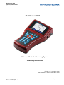
MultiSystem 4010
Universal Portable Measuring System
Operating Instructions
Revision 1.5 / August 16, 2012
TKZ L3160-00-75.00EN / L3160-00-75.10EN
© Hydrotechnik GmbH • All rights reserved
Rev. 1.5 / 120816 english
Page 1 of 45
MultiSystem 4010
Operating Instructions
Contents
1.
Safety ...................................................................................... 3
1.1. General Safety and Warning Hints .......................................... 3
1.2. Hints for the Use of the Measuring Instrument ........................ 3
1.3. Hints for the Use of Sensors and Cables................................. 3
1.4. Hints for the Use of rechargeable Batteries............................. 3
2.
Introduction ............................................................................ 4
2.1. Range of Validity...................................................................... 4
2.2. Copyright.................................................................................. 4
2.3. Limitation of Liability................................................................. 4
2.4. Use as Agreed ......................................................................... 5
2.5. Warranty Regulations .............................................................. 5
2.6. Obligations to the Customer .................................................... 5
2.7. Authorized Personnel............................................................... 5
3.
Description of the Measuring System ................................. 6
3.1. Qualities of the MultiSystem 4010 ........................................... 6
3.2. Inputs and Connectors............................................................. 6
3.3. Display ................................................................................... 10
3.4. Keyboard................................................................................ 11
3.5. Evaluation Software ............................................................... 12
3.6. Technical Data ....................................................................... 12
4.
Start-up ................................................................................. 13
4.1. Check Delivery ....................................................................... 13
4.2. Lieferumfang .......................................................................... 13
4.3. Charge Batteries .................................................................... 13
5.
First Steps............................................................................. 14
5.1. Switch Instrument On and Off................................................ 14
5.2. Select Operation Language ................................................... 15
5.3. Set Date and Time ................................................................. 15
5.4. Connect Sensors ................................................................... 16
5.5. Enter Sensor Parameters ...................................................... 16
5.6. Collect Measuring Data.......................................................... 17
5.7. Connect PC and transfer Measuring Data............................. 18
5.8. Delete Measuring Data .......................................................... 18
5.9. Reset Instrument.................................................................... 19
6.
Operation .............................................................................. 19
6.1. General Information ............................................................... 19
6.2. Measured Value Display ........................................................ 20
6.3. Main Menu ............................................................................. 21
6.4. Configure Channels ............................................................... 22
6.5. Configure Display................................................................... 31
6.6. Program a Recording............................................................. 33
6.7. Start a Recording ................................................................... 35
6.8. Present Measurement Series ................................................ 36
6.9. Delete Measuring Series........................................................ 40
6.10. Instrument Settings ................................................................ 41
7.
Cleaning and Maintenance.................................................. 44
7.1. Cleaning ................................................................................. 44
7.2. Calibration • Maintenance • Repair ........................................ 45
© Hydrotechnik GmbH • All rights reserved
Rev. 1.5 / 120816 english
Page 2 of 45
MultiSystem 4010
Operating Instructions
1.
Safety
1.1.
General Safety and Warning Hints
•
•
•
•
1.2.
Hints for the Use of the Measuring Instrument
•
•
•
•
•
•
1.3.
Never expose the instrument to excessive heat or moisture; obtain the technical data.
Do not store the instrument in humid or dusty locations or at temperatures below freezing point.
Never dip the instrument into water or other liquids. Never let liquids come into the instrument.
Never open the instrument and do not use it, after it fell down or the housing is damaged.
Avoid strong magnetic fields. Keep distance of electric motors or other instruments that generate
electro-magnetic fields. Strong magnetic fields may cause malfunctions and influence measuring
values.
Avoid the formation of condensed water. If condensed water has formated you should let the
instrument acclimate before you switch it on. Otherwise it could be damaged.
Hints for the Use of Sensors and Cables
•
•
•
•
1.4.
Never cut, damage or modify the power pack cables or place things on it.
Never touch the power pack with wet or moist hands. Only connect the power pack to power
supplies for which it is suited (see technical data).
Unplug the mains cable during a thunderstorm, or if you determine smoke or smell, or if the mains
cable is damaged.
Assure sufficient grounding of your installations. Inadequate grounding may lead to measuring
peaks.
Protect the sensors from exceeding the allowed power range, mechnical overload and wrong pin
assignment.
Assure to enter the sensor parameters correctly when using sensors without ISDS (Intelligent
Sensor Detection System).
The measuring cables MK 01 and MKS may not be lengthened. Otherwise the shielding will be
interrupted.
The data of an ISDS sensor are read into the measuring instrument during switch-on procedure. If
you connect new sensors, you will have to switch the instrument off and on.
Hints for the Use of rechargeable Batteries
•
•
•
•
•
•
•
Keep batteries away from heat sources and open fire.
Never dip batteries into water.
Never short-circuit the contacts of batteries.
Never dismount, repair or modify batteries.
Use only batteries that are mounted or delivered by the manufacturer.
Load only the battery while it is mounted in the instrument.
Used batteries are special waste. Cover the contacts with insulation tape.
© Hydrotechnik GmbH • All rights reserved
Rev. 1.5 / 120816 english
Page 3 of 45
MultiSystem 4010
Operating Instructions
2.
Introduction
Important Information
The information contained in this section is important. If you
neglect them, you might loose possible guarantee
demands.
2.1.
Range of Validity
The manual on hand is valid for measuring instruments named "MultiSystem 4010". It adresses to the
operator of this instrument, that means the person, who works with the instrument.
The manual is not a technical manual. Please contact our service staff for questions, that exceed the
contents of this manual.
2.2.
Copyright
The measuring instrument and this manual are protected on copyright. Manufacture without license
will be prosecuted by law. All rights reserved on this manual, even the reproduction and/or duplication
in any thinkable form, e.g. by photocopying, printing, on any data recording media or translated.
Reproduction of this manual is only permitted with a written approval of the manufacturer.
The technical state by the time of delivery of instrument and manual is decisive, if no other information
is given. Technical changes without special announcements are reserved. Earlier manuals are no
longer valid.
The general conditions of sale and delivery of Hydrotechnik GmbH are valid.
2.3.
Limitation of Liability
We guarantee the faultless functioning of our product in accordance with our advertising, the product
information edited by Hydrotechnik GmbH and this manual. Further product features are not
guaranteed. We take no liability for the economy and faultless function if the product is used for a
different purpose than that described in the chapter „Use as agreed“.
Compensation claims are generally impossible, except if intention or culpable negligence by the
manufacturer is proved, or if assured product features are not provided. If the product is used in
environments, for which it is not suited or which do not represent the technical standard, we are not
responsible for the consequences.
We are not responsible for damages at installations and systems in the surroundings of the product,
which are caused by a fault of the product or an error in this manual.
We are not responsible for the violation of patents and/or other rights of third persons outside the
Federal Republic of Germany.
We are not liable for damages, which result from improper operation according to this manual. We are
not liable for missed profit and for consecuting damages due to non regardance of safety advice and
warning hints. We don’t accept liability for damages which result from the use of accessoires which are
not delivered and/or approved by the manufacturer.
Hydrotechnik products are designed for a long life. They represent the standard of technique and
science and were checked on all functions individually before delivery. The electrical and mechanical
© Hydrotechnik GmbH • All rights reserved
Rev. 1.5 / 120816 english
Page 4 of 45
MultiSystem 4010
Operating Instructions
construction corresponds to the current norms and regulations. The manufacturer is doing product and
market research for the further development and permanent improvement of their products.
In case of faults and/or technical trouble please contact the Hydrotechnik service staff. We assure that
suitable measures will be taken immediately. The Hydrotechnik GmbH guarantee regulations are
valid, which we will send to you on demand.
2.4.
Use as Agreed
The measuring instrument "MultiSystem 4010" is a mobile hand-held device for the collection,
recording and evaluation of measured data, coming from sensors connected to the instrument. You
may connect various sensors to the instrument that correspond with the requirements stated in the
section „Technical Data“.
Any other use of this measuring instrument is regarded as „not intented use“. Please contact our
service staff if you have questions exceeding the contents of this manual or if you want to use the
device for a different purpose. We will be very much pleased to help you.
2.5.
Warranty Regulations
In accordance to our warranty regulations we guarantee the condition without defects for this
measuring instrument for a duration of six months. Wearing parts and storage batteries are excepted
from this warranty. The warranty is spoiled if repair work or interventions are executed by unauthorized
persons.
Within the warranty period we repair damage or defects which are caused by a manufacturing fault.
We only accept warranty claims if they are reported to us immediately after their discovery, but latest
six months after delivery. The warranty benefit is by our choice through repair of defective parts or
replacement by intact parts.
Send your instrument with an invoice copy or delivery note copy to our service department. The
address is given at the end of this manual.
2.6.
Obligations to the Customer
The operating authority of this product has to assure, that only persons who
•
•
•
know the regulations on working safety and accident prevention
have been instructed in the operation of this product
have read and understood this manual
can operate this product. Persons who operate this instrument are obliged to
•
•
2.7.
obey all regulations on working safety and accident prevention
read this manual completely, especially the safety instructions in the first chapter.
Authorized Personnel
Persons are authorized if they have a professional education, technical experience, knowledge of the
important norms and regulations and if they are able to estimate their duties and recognize possible
danger at an early time.
© Hydrotechnik GmbH • All rights reserved
Rev. 1.5 / 120816 english
Page 5 of 45
MultiSystem 4010
Operating Instructions
Operator of the instrument
Persons are authorized if they are trained in the operation of the instrument and have read and
understood this manual completely.
Personell for installation and maintenance
Persons are authorized if they are trained in all aspects of the instrument and have read and
understood this manual completely.
3.
Description of the Measuring System
3.1.
Qualities of the MultiSystem 4010
The MultiSystem 4010 is a practical, user-friendly hand-held measuring instrument for all daily
measuring duties. During start-up the device automatically detects connected ISDS sensors and uses
all parameters: measuring range, physical measurand, units, output signal and characteristic curve
(linearisation). A mix up of sensors or faulty entries are reliably avoided.
You may connect up to five sensors at a time and record their measured values. Five virtual channels
may be used for calculations, e.g. as difference, sum, performance or the first derivation (e.g. speed
calculated from distance). As an option you may use these channels to show measured values read
from a CAN bus. The recording of extreme values (the measured highest and lowest values) is
permanently active and can be displayed with one key pressure. You may also connect sensors
without ISDS to the MultiSystem 4010. Enter the sensor parameters in the channel menu manually.
It is possible to transfer all measuring series via an USB cord to a PC, or use the online mode to
display the values on a computer. The software HYDROcom is delivered free and provides extensive
software support with functions to evaluate, present and print measured values.
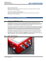
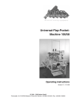
3.2.
Inputs and Connectors
1
6
3
2
5
9
4
8
7
© Hydrotechnik GmbH • All rights reserved
Rev. 1.5 / 120816 english
Page 6 of 45
MultiSystem 4010
Operating Instructions
1/2/3
4
5
6
7
8
9
3.2.1.
Input ch1 / ch2 / ch3 – analog inputs
Input ch4 – combined input analog / frequency
Input ch5 – frequency input
USB interface
Combined jack CAN / HYDROboot
Power supply – power pack
Digital input / output
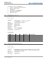
Analog inputs (ch1 / ch2 / ch3)
Signal input
Resolution
Measuring rate
Filter function
Connector
Protection type
Error limits
Linearity error
Temp.coefficient
20mA (selectable 0 … 20 mA or 4 … 20 mA)
10 V (selectable 0 ... 10 V or 2 ... 10 V
12 bit analog / digital converter
1.0 ms = 1 kHz
input filter 5 kHz
6 pole device jack
IP40
< ± 0.2 % of final value
< ± 0.1 % of final value
0.1 % per 10 °C
Pin assignment
Pin
1
2
3
4
5
6
Function
Signal I [mA]
GND
Ub*
Signal U [V]
Shield
ISDS
Ri.
50 Ω
Ci.
100 nF
11 kΩ
22 nF
Limitation
5.6 V DC
Protection type
transile diode
100 mA
current limitation
transile diode
Ub*: supply voltage at mains operation 24 V DC
3.2.2.
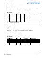
Combined input analog / frequency (ch4)
Signal input
Resolution
Measuring rate
Filter function
switchable analog- / frequency input; selectable 0 … 20 mA / 4 … 20 mA)
f-input (0.25 Hz … 5 kHz w.d., 0.25 Hz … 20 kHz wo.d.), signal type PNP
12 bit analog/digital converter
1 ms (1 kHz)
input filter 5 kHz
© Hydrotechnik GmbH • All rights reserved
Rev. 1.5 / 120816 english
Page 7 of 45
MultiSystem 4010
Operating Instructions
Connector
Protection type
Error limits
Linearity error
Temp.coefficient
6 pole device jack
IP40
≤ ±0.15 % of final value (analog) / ≤ ±0.05 % of measured value (frequency)
≤ ±0.10 % of final value (analog) / none (frequency)
≤ 0.1 % per 10 °C (analog) / none (frequency)
Pin assignment
Pin
1
1
2
3
4
5
6
Ub*:
1:
2:
3.2.3.
Function
Signal I [mA]
Frequency signal
GND
Ub*
Direction signal
Shield
ISDS
Ri.
50 Ω
4.75 kΩ
Ci.
100 nF
1 nF
Limitation
5.6 V DC
36 V DC
Protection type
transile diode
VDR transile diode
4.75 kΩ
1 nF
100 mA
36 V DC
current limitation
VDR transile diode
supply voltage at mains operation 24 V DC
channel set to analog measurement
channel set to frequency measurement
Frequency / counter input (ch5)
Signal input
Connector
Protection type
Error limits
5 ... 30 VDC, 0.25 Hz … 5 kHz w.d., 0.25 Hz … 20 kHz wo.d.,
signal type PNP and NPN
6 pole device jack
IP40
≤ ±0.05 % of measured value
Pin assignment
Pin
1
2
3
4
5
6
Function
Frequency signal
GND
Ub*
Direction signal
Sield
ISDS
Ri.
4.75 kΩ
Ci.
1 nF
Limitation
36 V DC
Protection type
VDR transile diode
4.75 kΩ
1 nF
100 mA
36 V DC
PTC
VDR transile diode
Ub*: supply voltage at mains operation 24 V DC
© Hydrotechnik GmbH • All rights reserved
Rev. 1.5 / 120816 english
Page 8 of 45
MultiSystem 4010
Operating Instructions
3.2.4.
Digital trigger input (ch6)
Pins of the digital input/output; the trigger input is separated galvanically.
Pin assignment
Pin
3
4
Function
Signal*
GND
Limitation
33 V DC
Protection type
VDR transile diode
*: 1 mA constant current
Attention
Damage to the instrument possible!
This input may not be connected to inductive consuments directly
(e.g. coil of a magnetic valve). Otherwise the instrument can be
damaged.
3.2.5.
Digitaler trigger output (ch7)
Jacks of the digital input / output.
Pin assignment
Pin
1
2
3.2.6.
Function
GND
Signal
Limitation
Protection type
Ub*/10 mA
VDR transile diode
Interface CAN / RS232
Use
Connector
Protection type
CAN, MultiXtend, HYDROboot
8 pole M12-1 jack
IP40
© Hydrotechnik GmbH • All rights reserved
Rev. 1.5 / 120816 english
Page 9 of 45
MultiSystem 4010
Operating Instructions
Pin assignment
Pin
1
2
3
4
5
6
7
8
Function
GND
power supply for MultiXtend or CAN sensors*
DTR
CAN_H
TXD
RTS from PC (input)
GND
RXD
*: ~ 21.5 VDC / 200 mA (mains operation) / ~ Ub / 200 mA (battery)
3.2.7.
USB interface
Micro USB interface for PC communikation
3.3.
Function
Signal D+
Signal D–
VCC
Color
green
white
red
GND
black
Remarks
twisted cable
twisted cable
delivers max. 500 mA from host for device power supply
(not used by instrument)
–
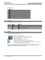
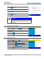
Display
The instrument has a color display where all information and measured values are displayed. Some
icons may be displayed in the bottom line:
Recording bar
indicates a running recording:
trigger recording not started, filling the pretrigger memory
trigger incident not happened, pretrigger is full
recording in progress
SD card: a formatted SD card is inserted
USB: instrument connected to a PC via the USB interface
batteries: charging status of the batteries; recharging required when icon is red
mains operation: batteries are being recharged
During normal operation either the battery or the mains operation icon is displayed. If the battery icon
flashes during mains operation, either no batteries are built in, they are defective or deeply
discharged, or the battery cable is not connected properly.
© Hydrotechnik GmbH • All rights reserved
Rev. 1.5 / 120816 english
Page 10 of 45
MultiSystem 4010
Operating Instructions
3.4.
Keyboard
The MultiSystem 4010 is equipped with a valuable keypad that is insensitive against humidity and dirt.
The 26 keys are occupied as follows:
...
Function keys; the current occupation is shown in the bottom line of the display
above the corresponding key
Keys to switch the instrument on and off
Cursor keys; move highlighting bars or the cursor into the desired direction
Enter key; confirms entries or commands
Menu key; opens the main menu from where all instrument functions are
accessible
Escape key; aborts entries or commands
...
Ten key pad; used to enter numbers and letters
Key to enter punctuation marks and special characters
Clear key to delete a single character during entries
© Hydrotechnik GmbH • All rights reserved
Rev. 1.5 / 120816 english
Page 11 of 45
MultiSystem 4010
Operating Instructions
3.5.
Evaluation Software
Important
Instrument not compatible with elder software versions!
Use HYDROcom 6 with at least version 6.3.0.20 for the communication
with the MultiSystem 4010. Otherwise the measuring data cannot be
transferred correctly. The current version is contained on the data CD of
your instrument or in the dowload section of www.hydrotechnik.com.
The evaluation software HYDROcom is part of the delivery. After transfering the measuring data to a
PC you may use the application to evaluate, process and present them.
3.6.
Technical Data
Casing
Weight
Protection type
CE-label
Power supply
ABS plastic
841 g
IP40
complies with EN 50 081-1 and EN 50082-1 – RoHS
internally: NiMh batteries, 14.4V / 2,150 mAh;
externally: 24 V DC / 630 mA
Dimensions
225 x 123 x 60 mm (L x W x H)
Interfaces
USB 2.0, CAN, RS232
Environmental temperature 0 … +45 °C
Relative humidity
0 … 80% (not condensing)
Storage temperature
-20 … +50 °C
Value display
5 digit
Trigger
channel, key
Scan rate
settable from 1 ms to 999 min
Measuring rate
1 ms (1 kHz)
Memory
SD carde 2 GB, max. 100 measuring series
max. 4 MB / measuring series (1 million values)
Error limits
analog: ± 0.2% of final value; digital: ± 0.02 % of measured value
© Hydrotechnik GmbH • All rights reserved
Rev. 1.5 / 120816 english
Page 12 of 45
MultiSystem 4010
Operating Instructions
4.
Start-up
4.1.
Check Delivery
The measuring instrument is delivered by Hydrotechnik and transported by suited shipping
companies. At the time of delivery you should check:
• Does the number of delivered items corresponds with the Hydrotechnik delivery note?
• Is the packing free of visible damage?
• Are measuring instrument and accessories free of visible damage?
• Are there any indications of rough treatment during transportation (e.g. burn marks, scratches,
color)?
To maintain all demands against the shipping company you should document all possible
transportation damage (e.g. by taking photos and signing a written protocol), before you put the
instrument into operation.
Hydrotechnik is not responsible for transportation damage and will take no liability.
4.2.
Lieferumfang
Carefully remove the transportation packing. Please obtain all rules and regulations for the disposal of
packing materials. After unpacking you should find the following parts:
•
•
•
•
Measuring instrument MultiSystem 4010, 3160-00-75.00
CD with software HYDROcom, 8874-16-00.01
Power pack, 230 VAC / 24 VDC, 625 mAh, 8812-20-02.00
USB data transmission cable, 8824-F8-01.50
Check the range of delivery in accordance to the delivery note and the order documents. Report
differences instantly to Hydrotechnik. Later claims on incomplete delivery cannot be accepted.
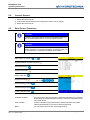
4.3.
Charge Batteries
Attention
Battery performance endangered!
Charge the instrument batteries for 14 to 16 hours before you put the
instrument into operation. Otherwise there is the danger of excessive
discharge, which would influence the battery performance negatively.
The internal NiMH batteries of the instrument are charged when the device is connected to mains
power with a Hydrotechnik power pack. The batteries are slightly pre-charged and should be charged
for 14 to 16 hours before the instrument is put into operation. Empty batteries are indicated with a
flashing battery icon in red color.
© Hydrotechnik GmbH • All rights reserved
Rev. 1.5 / 120816 english
Page 13 of 45
MultiSystem 4010
Operating Instructions
Hints for the treatment of the batteries
The life cycle of NiMH cells can be very long, but it depends on the conditions of use. Avoid a
complete discharge, continuous charging and immediate re-charging after every use. This triggers the
memory effect with a minimization of the battery capacity and possible remanent damage. You can
regenerate the battery by several discharge and charge cycles.
In case of low battery power a hint "Load batteries" will be displayed. In this case you should maintain
a 16 hour charging time. In case of longer periods without use you should discharge and charge the
batteries monthly.
5.
First Steps
This section provides information for the daily use of the instrument. These operations are explained:
•
•
•
•
•
•
•
•
switch instrument on and off
select operation language
connect sensors
enter sensor parameters
collect measuring data
connect to a PC and transfer measuring data
delete measuring data
reset the instrument
After this chapter you will find a complete description of the instrument software with a chronological
presentation and explanation of all menus.
Information
The software HYDROcom is part of the delivery but will not
be described in this manual. Please see the online help
and the software manual.
5.1.
Switch Instrument On and Off
Information
Assure before switching on that the desired ISDS sensors
are connected (see section 5.4 on page 16).
© Hydrotechnik GmbH • All rights reserved
Rev. 1.5 / 120816 english
Page 14 of 45
MultiSystem 4010
Operating Instructions
Switch on:
(> 2 sec.)
Wait for the self-test until the measured values are displayed
Use the instrument
Switch off:
(> 2 sec.)
Information
When using ISDS sensors the sensor parameters will be
set automatically. When using other sensors you will have
to program the parameters before you can execute
measurements.
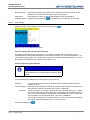
5.2.
Select Operation Language
Open function:
[Device]
Do selection:
Confirm selection:
Accept changes:
5.3.
Set Date and Time
Open function:
[Device]
Highlight item „Date“:
Enter and confirm date:
Highlight item „Time“:
Enter and confirm time:
Accept changes:
© Hydrotechnik GmbH • All rights reserved
Rev. 1.5 / 120816 english
Page 15 of 45
MultiSystem 4010
Operating Instructions
5.4.
Connect Sensors
1. Switch the instrument off.
2. Connect the desired sensors to the inputs (see section 3.2 on page 6).
3. Switch the instrument on.
5.5.
Enter Sensor Parameters
Information
The sensor parameters will be detected automatically when you
have connected ISDS sensors. You may skip this section.
Information
The parameters of sensors without ISDS functionality must be
entered manually. You find this information on the type plate or in
the documentation or calibration certificate of the sensor.
Open menu „Channels“:
Highlight desired measuring channel:
Start programming:
Highlight menu item:
Select menu item:
Highlight a setting:
…
or enter a value,
e.g. 12.5:
Confirm setting or value:
Terminate programming:
Leave „Channel“ menu:
Available variables
Index variable
Name
© Hydrotechnik GmbH • All rights reserved
Rev. 1.5 / 120816 english
the instrument is able to process 37 different measurands, e.g. pressure,
temperature and rotational speed; assure to select the measurand of the
connected sensor
if identic variables are programmed for several channels, they will be
indexed automatically in the order of their programming
you may add a name to each measuring channel
Page 16 of 45
MultiSystem 4010
Operating Instructions
Signal type
Measuring range
select the sensor output signal ("0/20 mA", "4/20 mA", "0/10 V", "2/10 V")
enter beginning and end of the measuring range and confirm both entries
with
press
to execute the automatic zero point equalisation; assure that
the sensor has no load and press
to run the equalisation; a possible
zero point deviation will be calculated in the software
you may enter a calibration table for the connected sensor after setting
„Yes“ at the menu item „Linearisation“; please see the corresponding
section on page 23
Zero point
Linearisation
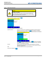
5.6.
Collect Measuring Data
Measured values are collected as measuring series that can be configured in the menu „Memory“.
Select function:
Select channels to be recorded:
Confirm selection:
Open recording functions:
or enter a value, e.g. 12.5:
Highlight setting:
Confirm setting or value:
Terminate programming:
Channels
Storing time
Scan rate
activate the channels that shall be recorded
decide how long measured values shall be recorded and choose the time units
enter the intervals between two measurements and choose the time units
Information
Storing time and scan rate define, how long and often values are
recorded. It is recommended to keep the amount of recorded measuring
data as small as possible to ease the later evaluation and presentation.
Trigger event
a trigger is a condition that must happen before a recording may start or end; here
“p1” is defined, that means the recording will start if the p1-value exceeds 200.
Please see section 6.6 on page 33 for information on the use of triggers.
© Hydrotechnik GmbH • All rights reserved
Rev. 1.5 / 120816 english
Page 17 of 45
MultiSystem 4010
Operating Instructions
5.7.
Connect PC and transfer Measuring Data
Information
The software HYDROcom must be installed on your PC
before you are able to transfer measuring data.
1. Switch on measuring instrument and PC.
2. Plug the delivered USB cable into the connector at the side of the instrument (see section 3.2 on
page 6).
3. Plug the USB cable into an USB interface of your PC.
4. Wait until the instrument has been detected properly.
5. Execute the data transfer like described in the software manual.
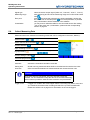
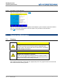
5.8.
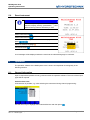
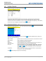
Delete Measuring Data
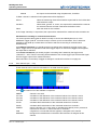
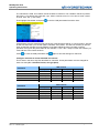
Saved measuring series can be deleted in the delete menu:
Open the function:
[Memory]
Select measurement series:
Start deletion:
Confirm deletion:
In the shown example the measuring series 01, 02 and 04 are selected for deletion, a green check
mark is displayed left of them. Now you may:
selects all measuring series for deletion
previous page
next page
deletes the selected measuring series
© Hydrotechnik GmbH • All rights reserved
Rev. 1.5 / 120816 english
Page 18 of 45
MultiSystem 4010
Operating Instructions
5.9.
Reset Instrument
Important Information
All customer-specific parameters and settings
(channels, display, memory, presentation, …) and
saved measuring data are deleted by a reset.
Switch instrument off:
Switch instrument on:
Wait until the beginning of the initialization is displayed and then
press:
Select the desired language
Confirm the reset:
A red message will be displayed where the reset into the selected language is confirmed.
6.
Operation
The operation software of the MultiSystem 4010 is shown and explained chronologically in the
following sections.
6.1.
General Information
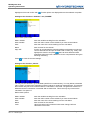
Input is required and possible at many positions within the operation software. Then one of three input
types will be required.
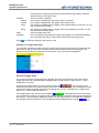
Selection from Lists
A list selection is possible, e.g. when selecting the measurand during channel programming:
Use the arrow keys to highlight the list desired list item and then press
© Hydrotechnik GmbH • All rights reserved
Rev. 1.5 / 120816 english
.
Page 19 of 45
MultiSystem 4010
Operating Instructions
Numerical Input
to enter the decimal point and confirm the input
Use the numeric keys of the instrument. Press
. The value „125.2“ is entered in this way:
with
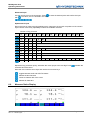
Alphanumeric Input
During the input in options requiring alphanumeric characters, the second occupations of the numeric
keys is active. Press a key repeatedly to select the available character:
Number of key pressures
1x
2x
3x
4x
5x
6x
A
B
C
2
Ä
Æ
D
E
F
3
É
G
H
I
4
J
K
L
5
M
N
O
6
Ö
P
Q
R
S
7
T
U
V
8
Ü
W
X
Y
Z
9
–
.
+
,
/
7x
8x
9x
10x
11x
12x
13x
14x
15x
(
)
?
!
@
°
:
²
%
1
0
Ø
*
bei 1x Drücken erscheint eine Leerstelle
Repeat the key pressures quickly, otherwise the cursor jumps to the next digit. Press
character left of the cursor.
to delete the
Move the cursor with the arrow keys and use the four function keys:
toggles between small and CAPITAL letters
deletes the last character
inserts a character left of the cursor
deletes all characters
6.2.
Measured Value Display
© Hydrotechnik GmbH • All rights reserved
Rev. 1.5 / 120816 english
Page 20 of 45
MultiSystem 4010
Operating Instructions
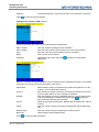
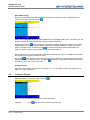
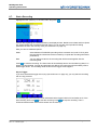
The current measured values are displayed after initialisation. You may select the shown channels in
the display menu. Use one of two display modes:
•
•
measured values with units (left image)
measured values with minimal and maximal values (right image)
The active display mode is displayed in the lower left corner. Press
and
to stop the refresh of the values (“freeze” the display). Press
to toggle the display mode
again to enable the refresh.
in MinMax mode to delete the extreme values. Then the new extreme values will be
Press
measured instantly.
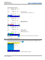
6.3.
Main Menu
All settings and programmings of the instrument are done in the menu structure accessible from the
to open it:
main menu. Press
Use the arrow keys to highlight a menu and press
Channels
Display
Memory
Device
to open it:
contains all commands and functions to program the channels of the instrument
select channels to be displayed and configure the display
configure recordings and manage saved measuring data
general settings to adapt the instrument for your personal needs
When a menu is highlighted, the F-keys are occupied with several functions:
Quick access keys „Channel“ menu
opens the channel programming for the measuring channels C1 … C5
Quick access keys „Display“ menu
toggles the display modes „Text“ / „Graphic“
Quick access keys „Memory“ menu
starts the recording
opens the presentation menu where you can display recorded measuring data
opens the delete menu where you may delete recorded measuring data
Quick access keys „Device“ menu
enables or disables the defined filter settings
© Hydrotechnik GmbH • All rights reserved
Rev. 1.5 / 120816 english
Page 21 of 45
MultiSystem 4010
Operating Instructions
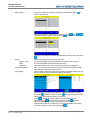
6.4.
Configure Channels
Highlight „Channels“ in the main menu and press
:
You can see a list of all twelve channels of the instrument. The first five are the physical input
channels (see section 3.2 on page 6), C6 and C7 are the trigger input resp. output. The other
channels can be used for calculations or may be occupied with digital input signals (e.g. CAN, option).
Use the arrow keys to highlight a channels and press
6.4.1.
to open it.
Analog Input Channels (C1 … C3)
Highlight one of the channels C1 … C3 in the channel menu and press
Use the arrow keys to highlight a menu item and press
menu items have these functions:
Meas. Variable
Index Variable
Name
Signal type
Measuring range
Zero point
Linearisation
Press
:
to edit the displayed value / setting. The
type and units of the measurand of the sensor connected to this channel
identic variables are indexed automatically
enter the desired name of the channel
select the signal type of the connected sensor (0/4-20 mA or 0/2-10 V)
enter the start and end values of the measuring range
function to execute a zero point equalisation of the sensor; connect the
sensor with a load of „0“ (e.g. no pressure), highlight „Zero point“ and
press
; press
to start the equalisation, then the compensation
value will be displayed
here you may enter (or select) a linearisation table to compensate the
linearity error of the sensor (see below)
after finishing the inputs to save all settings.
© Hydrotechnik GmbH • All rights reserved
Rev. 1.5 / 120816 english
Page 22 of 45
MultiSystem 4010
Operating Instructions
How to use a Linearisation Table
A linearisation table contains must- and is-values for several reference points of the sensor measuring
range. They are determined during the calibration of the sensor and are used to (partly) compensate
the linearisation error of the sensor. The measuring error of a sensor can be reduced significantly by
using a linearisation table.
The instrument can use linearisation tables with ten must-is value pairs. These are either transferred
by ISDS from the sensor to the instrument, or must be entered manually. Up to five manually entered
linearisation tables can be saved and re-used.
Information
Please see the calibration certificate of the sensor for the must- and is-values.
1.
Open the configuration menu of the channel, highlight the item „Linearisation“ and press
set the setting to “Yes”.
2.
Highlight the item „Table“ and press
3.
Highlight one of the saved linearisation tables or an empty space and press
4.
Enter a name for the linearisation table (e.g. serial number of the sensor).
5.
Highlight the line „Ref. Point 1“ and press
6.
Enter the must-value („Ref.“) and confirm with
7.
8.
Enter the corresponding is-value („Act.“) and confirm with
Repeat that to enter all must-is-values.
9.
10.
Press
Press
to
:
:
.
.
.
after entering the last value to leave the input mode.
to save the linearisation table.
© Hydrotechnik GmbH • All rights reserved
Rev. 1.5 / 120816 english
Page 23 of 45
MultiSystem 4010
Operating Instructions
6.4.2.
Combined Input Channel (C4)
Highlight channel C4 in the channel menu and press
:
The combined input channels can be used for sensors with analog or frequency output signal. The
channel is set by selecting the appropriate signal type.
to modify the value/setting. Different menu
Use the arrow keys to highlight a menu item and press
items will be displayed, dependant on the use of the combined input channel.
Use as analog input channel (left image)
The configuration is the same as that of the analog input channels C1 … C3 described in section 6.4.1
on page 22.
Use as frequeny channel (center image)
Meas. variable
Index Variable
Name
Signal type
Calibr. value
Linearisation
type and units of the measurand of the sensor connected to this channel
identic variables are indexed automatically
enter the desired name of the channel
select the signal type of the connected sensor: frequency either with or
without direction detection
enter the factor used to multiple the frequency value to calculate the
measured value (e.g. the number of cogs when measuring the rotational
speed at a cogged wheel)
here you may enter or select a linearisation table to reduce the
linearisation error of the sensor (see explanations in the section „How to
use a linearisation table“ on page 23)
Use as counter channel (right image)
Meas. variable
Index Variable
Name
Signal type
Pulse value
Linearisation
Press
type and units of the measurand of the sensor connected to this channel
identic variables are indexed automatically
enter the desired name of the channel
select counter either with or without direction detection
enter the volume that shall be calculated for each counting impulse (e.g.
the geometric tooth volume for gear flow meters)
here you may enter or select a linearisation table to reduce the
linearisation error of the sensor (see explanations in the section „How to
use a linearisation table“ on page 23)
after finishing the inputs to save all settings.
© Hydrotechnik GmbH • All rights reserved
Rev. 1.5 / 120816 english
Page 24 of 45
MultiSystem 4010
Operating Instructions
6.4.3.
Frequency input channel (C5)
Highlight channel C5 in the channel menu and press
. The channel can be used as frequency or
counter channel, please see section 6.4.2 on page 24 for information on the programming.
6.4.4.
Trigger input channel (C6)
Highlight channel C6 in the channel menu and press
:
You may feed an external signal via the trigger input channel into the instrument to start a recording.
Please see section 3.2.4 on page 9 for information on allowed trigger signals.
This channel may also be used to start recordings on several measuring instruments simultaneously.
Please see the section “Simultaneous recording on connected instruments” on page 26.
Here you may only enter a name. Press
6.4.5.
to save the entered name.
Trigger output channel (C7)
Highlight channel C7 in the channel menu and press
:
The trigger channel may be used to start a simultaneous recording on connected instruments. Please
see the section “Simultaneous recording on connected instruments” on page 26.
Here you may define these parameters:
Name
Operation mode
Inactive
Meas. channel
Trigger event
© Hydrotechnik GmbH • All rights reserved
Rev. 1.5 / 120816 english
enter a name for the channel
select one of four modes
channel not used
a measuring channel is supervised for the entry of a certain incident that
can be defined with the parameters “Source”, “Condition” and “Value”
(see below); if it happens, the ouput will be switched
switches the output when the recording is started by a defined trigger
(see section 6.6 on page 33); this function is used to synchronize
recordings on connected instruments (see below)
Page 25 of 45
MultiSystem 4010
Operating Instructions
Manual
the output can be switched using the parameter „Condition“
If „Meas. channel“ is selected, further parameters will be displayed:
Source
select the measuring channel that shall be supervised for the incident that
shall switch the output
select either „greater“ or „lower“; the output will be switched if the value at
the selected channel exceeds / falls below the defined value
enter the value for the condition
Condition
Value
In the image channel p1 is supervised, the output will be switched if the measured value exceeds 120.
Simultaneous recording on connected instruments
You need a special cable (order No 8824-F2-00.50) to connect two MultiSystem 4010, or the
MultiXtend Trigger (order No 316A-A0-00.50) to connect up to five instruments. Then it becomes
possible to start build up a master-slave connection and start a recording on all instruments
simultaneously.
At the Master Instrument you should program a recording that is started by a trigger event. Then
select “Trigger event” as operation mode of the trigger output. As soon as the trigger event happens,
the output will be switched.
At the Slave Instruments you should program a recording that is started by the trigger event
„Channel E1 – ON”. Then the recording will be started as soon as the trigger input receives the signal
from the trigger output of the master instrument.
More information on the setup of trigger recordings is contained in section 6.6 on page 33.
6.4.6.
Free channels (C8 … C12)
These channels can be used for calculations or as CAN channels (option).
Press
UNDEF.
Ch1-Ch2
Ch3-Ch4
Ch4-Ch5
Ch1/dt
Ch5/dt
POWER
CAN
Multimeter
and select one of the available occupations:
channel is not used
calculation of the difference of the measured values from channel 1 and 2
calculation of the difference of the measured values from channel 3 and 4
calculation of the difference of the measured values from channel 4 and 5
calculates the first derivation of the measured values from channel 1
calculates the first derivation of the measured values from channel 5
uses the formula „Ch1 x Ch5 / 600“ to calculate the hydraulic power; pressure is
measured on channel 1, volume flow rate on channel 5
a signal from a connected CAN bus (option) is assigned to the channel
the signal from a Multimeter connected to the instrument is assigned to this
channel
© Hydrotechnik GmbH • All rights reserved
Rev. 1.5 / 120816 english
Page 26 of 45
MultiSystem 4010
Operating Instructions
Highlight an item and confirm with
. Further options are displayed due to the selected occupation.
Settings at the functions “ChX-ChY” and „POWER”
Define these options here:
Meas. variable
Index variable
Units
Name
Align. diff.
Press
enter the variable resulting from the calculation
enter the index number of the variable if you have several identic
enter the name of the units resulting from the calculation
enter a name for the channel
function to compensate the measuring difference between two sensors;
connect both sensors and put an identic load on them (e.g. 0 bar); then
; the instrument determins both
highlight this function and press
measured values and uses a difference for the compensation during the
following measuring
to save the channel settings.
Settings at the function „Chx/dt“
You may use this function e.g. to calculate speed from a measured way. You may define a threshold
value (“Level”) to prevent the calculation of absurd values for small way measurements. This assures
that a certain way has to be measured before a calculation is executed. The gate time assures for a
defined level that a calculation is executed after a certain time. This is the only way to assure the
calculation of a speed “0”.
Define these options:
Meas. variable
Index variable
Units
Name
Level
© Hydrotechnik GmbH • All rights reserved
Rev. 1.5 / 120816 english
enter the variable resulting from the calculation
enter the index number of the variable if you have several identic
enter the name of the units resulting from the calculation
enter a name for the channel
value for that the basic measured value must change, before a
calculation is executed
Page 27 of 45
MultiSystem 4010
Operating Instructions
Gate time
Press
maximal waiting time in milli-seconds until a new calculation is executed
to save the channel settings.
Settings at the function „CAN“ (Option)
At first the standard parameters for the measured data are displayed:
Meas. variable
Index variable
Units
Name
enter the variable resulting from the calculation
enter the index number of the variable if you have several identic
enter the name of the units resulting from the calculation
enter a name for the channel
Parameter
highlight this menu item and press
parameters:
to display the CAN specific
Here you may enter the CAN parameters of the connected sensor or MultiXtend module. The required
information can be found in the documentation of the device.
Specification
Timeout
Identifier
Format
Offset
Number bytes
Byte order
Press
select between CAN 2.0A (standard for Hydrotechnik products) or CAN
2.0B (e.g. at some third-party sensors)
enter the timeout period in seconds; the instrument will wait for this time
for new signals, before an error message is displayed
enter the identifier of sensor or MultiXtend device; you may either enter it
in decimal (standard) or hexadecimal places; press
to toggle the
entry mode after selecting the menu item
select the CAN data format (TEXT, BINARY BYTE, BINARY BIT, PDO or
FLOAT)
enter the number of bytes of the CAN message after that the data bytes
start
enter the number of bytes containing the measured value
select between Little and Big Endian)
to save the CAN parameters.
© Hydrotechnik GmbH • All rights reserved
Rev. 1.5 / 120816 english
Page 28 of 45
MultiSystem 4010
Operating Instructions
Settings at the function „Multimeter“ (Option)
Here you may assign a name to the channel and select the type of the connected Multimeter.
Currently the types Voltcraft VC 820, VC 920, 940 and 960 are supported.
Press
6.4.7.
to save the channel settings.
Configure channels for particle counter Patrick
Information
The values for Node-ID, baud rate and interface can be set in the
Patrick operation menu. Only use the settings programmed there, or
set them to the standard settings used in the following sections.
The instrument must be equipped with the option „CAN“ to be able to
connect the particle counter Patrick (3160-00-76.00). Additionally you
need the cable 8824-T6-05.00 (length 5.0 m) or 8824-T6-10.00 (length
10.0 m).
Patrick produces measuring data for the four particle size classes 4 / 6 /
14 / 21 µm according to ISO- or SAE-norms. One free channel is required
to display each particle size class, the MultiSystem 4010 is able to display
the maximum of five size classes. Typically only four size classes either according ot ISO or SAE will
be displayed.
Configure a channel for a size class
Open the menu “Channels”, highlight a free channel (e.g. Ch8) and press
shown here:
© Hydrotechnik GmbH • All rights reserved
Rev. 1.5 / 120816 english
. Set the options as
Page 29 of 45
MultiSystem 4010
Operating Instructions
The calculation is CAN, since Patrick sends the data via CAN bus. The variable P stands for particle,
the index is 1 for particle size class ISO 4 µm, what is used as name, too. You have to enter a name
as units, here “SC” (= size class).
Then highlight „Parameter“ and press
to set the CAN parameters like shown here:
All parameters must be defined exactly like shown, otherwise there will be no communication. Specific
for the size class ISO 4 µm are the options „Identifier“ and „Offset“. For ISO size classes you should
enter an identifier resulting from the addition of the Patrick Node-ID (see type plate or Patrick
operation menu) plus 384 (here Node-ID 125: identifier = 125 + 384 = 509). For SAE size classes you
must add 640 to the Patrick Node-ID.
Press
to save the CAN parameters and
again to save the settings for channel 8.
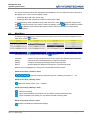
Configure channels for further ISO/SAE size classes
This is done in the same way like described for channel 8. Some parameters must be changed for
each size class (IP* = Identifier Patrick, see type plate):
Parameter
Channel
Index variable
Name
Identifier
Offset
Parameter
Channel
Index variable
Name
Identifier
Offset
© Hydrotechnik GmbH • All rights reserved
Rev. 1.5 / 120816 english
4 µm
C8
1
ISO 4 µm
IP* + 384
4
ISO classes
6 µm
14 µm
C9
C10
2
3
ISO 6 µm
ISO 14 µm
IP* + 384
IP* + 384
5
6
21 µm
C11
4
ISO 21 µm
IP* + 384
7
4 µm
C8
1
SAE 4 µm
IP* + 640
4
SAE classes
6 µm
14 µm
C9
C10
2
3
SAE 6 µm
SAE 14 µm
IP* + 640
IP* + 640
5
6
21 µm
C11
4
SAE 21 µm
IP* + 640
7
Page 30 of 45
MultiSystem 4010
Operating Instructions
More CAN settings
Now you muste enable the power supply and send a start command to Patrick. Highlight the item
„Device“ in the main menu and press
:
Stellen Sie die Baudrate auf den im Patrick-Bedienmenü eingestellten Wert (hier: „125 kBit/s“) ein und
aktivieren Sie die Stromversorgung des CAN Bus (CAN Power „EIN“).
Drücken Sie zunächst
um Spannung auf die CAN Schnittstelle zu legen. Schließen Sie nun den
Partikelzähler an und öffnen Sie anschließend wieder den gezeigten Bildschirm. Markieren Sie die
um die Kommunikation zwischen Messgerät und
Option „CANopen Gerät“ und drücken Sie
Patrick zu starten. Kehren Sie anschließend zum Hauptmenü zurück.
Set the baud rate to the value contained in the Patrick operation menu (here: „125 kBit/s“) and enable
the CAN bus power supply (CAN Power „ON“).
Now press
to put voltage on the CAN interface. Connect Patrick and then open this screen again.
to start the communication between instrument
Highlight the option „CANopen device“ and press
and Patrick. Then return to the main menu.
Display channels
Open the menu „Display“ and select the channels C8 … C11 for display. Please see chapter 6.5 on
page 31 for more information.
6.5.
Configure Display
Highlight „Display“ in the main menu and press
:
Here you may select which channels are displayed and how:
Channels
press
© Hydrotechnik GmbH • All rights reserved
Rev. 1.5 / 120816 english
and select the channels to be displayed:
Page 31 of 45
MultiSystem 4010
Operating Instructions
Display rate
Contrast
Presentation
Scaling
Highlight a channel and press
to display / hide it. All channels with a green
check mark will be displayed. Press
to confirm the channel selection.
define how often the display shall be refreshed with new measured values; this
settings does not influence the scan rate, that means those time intervals after that
new measured values are requested from the sensor
controls the brightness of the display
select whether the measured values shall be displayed as text or line diagram
(„Graphic“); if you select „Text“ you may select the color of the measured values in
the line below; if “Graphic” is selected, further settings will be displayed:
defines which part of the measuring range of each channel will be displayed:
to toggle between the input modes „User“ (manual input of scaling
Press
values) and „Auto“.
USER
and enter the lower limit of the desired display
highlight a channel, press
, enter the upper limit and confirm with
; repeat that for all
range; press
desired channels
AUTO
press
to define the scaling range for the highlighted channel automatically, or
to do this for all channels; the sensor measuring ranges will be used as scaling
ranges
Confirm the scaling with
.
here you may select the colors and symbols used to distinguish the channels in the
line diagram:
Colors/Symbols
© Hydrotechnik GmbH • All rights reserved
Rev. 1.5 / 120816 english
Page 32 of 45
MultiSystem 4010
Operating Instructions
Highlight a channel, press
, select the desired colors and confirm with
;
; repeat this for all desired channels.
select the desired symbol and confirm with
Press
press
Press
6.6.
to enable/disable the colors, or
to confirm the settings.
to enable/disable the symbols;
to terminate the settings in the display menu.
Program a Recording
Highlight „Memory“ in the main menu and press
:
In this menu you define, which channels are recorded and how:
Channels
Storing time
Scan rate
Trigger event
highlight the function and press
to select the channels to be recorded:
to check / uncheck it; all channels with green
Highlight a channel and press
check marks will be recorded; press
to finish the channel selection
defines how long the recording shall last; first enter a value and then select the
time unit second, minute or hour
defines the time intervals between two measured values; first enter a value and
then select the time unit milli-second, second or minute
by defining a trigger you may start the recording at exactly that moment when
interesting data are measured; one of the channels Ch1 … Ch7 can be supervised
for the fulfillment of a condition; with the trigger event “Key” you may start the
© Hydrotechnik GmbH • All rights reserved
Rev. 1.5 / 120816 english
Page 33 of 45
MultiSystem 4010
Operating Instructions
Condition
greater
smaller
rising
falling
Value
Pretrigger
Press
recording with a single key pressure from the measured value display; select the
desired channel or the option “Key”
select one of four conditions:
the condition if fulfilled when the trigger value is exceeded
the condition if fulfilled when the trigger value is fallen below
the condition is fulfilled when the trigger value is fallen below by more than 5 % and
then exceeded (rising edge)
the condition is fulfilled when the trigger value is exceeded by more than 5 % and
then fallen below (falling edge)
enter the trigger value here
the recording may start before the trigger event happens; the defined percentage
of the recording time will be used to save values before the trigger event
to confirm the settings in the memory menu.
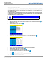
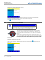
Example for a Trigger Recording
You supervise a pressure system and want to record data as soon as the pressure p1 falls below the
value 120 bar. But you also want to record the last 30 seconds before this event (pretrigger, see
below) and record data for a total time of 100 seconds. This is the correct configuration:
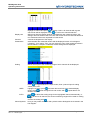
How the Pretrigger works
If a recording has been configured with a pretrigger, the instrument will start to fill a buffer memory
(trigger memory) with measuring data immediately after leaving the menu “Start memory”. This is
indicated by a bar chart.
As long as the trigger buffer is not full, the bar is colored red (
). The recording can be
started, but there are not enough measuring data for the desired pretrigger. The recording time will be
reduced accordingly (example: programmed recording time 100 sec., pretrigger 50 %, trigger event
after 30 sec., total recording time 80 sec.).
If the trigger buffer is full, the bar is colored green (
). If the trigger event does not happen
yet, the measuring values in the trigger buffer will be overwritten, so that the most topical values are in
the memory. If the recording is started, the values from the trigger buffer are recorded and completed
to the programmed recording time. The recording bar will be displayed blue on white (
).
© Hydrotechnik GmbH • All rights reserved
Rev. 1.5 / 120816 english
Page 34 of 45
MultiSystem 4010
Operating Instructions
6.7.
Start a Recording
Highlight the item „Memory“ in the main menu and press
:
Several data regarding the intented recording are displayed here. Beside current date and time (these
are used to identify the recording and as file name) you can see the most important recording
parameters as set in the memory menu (see section 6.6 on page 33).
Here you have to additional options:
Mode
Note
select between STANDARD (recording will be executed once) and CYCLIC (after
the recordinf the instrument will be on stand-by to repeat the recording with identic
parameters)
you may add some text to the recording that will be saved together with the
measuring data
Press
to start the recording. The instrument will immediately start to record measuring data, if no
trigger has been defined. If trigger and pretrigger are defined, the instrument will immediately start to
fill the trigger buffer. The recording starts as soon as the trigger event happens.
Key as Trigger
If you have selected the trigger event „Key“(see section 6.6 on page 33), you may start the recording
with one key pressure:
The recoding bar in the left lower corner indicates that the trigger buffer is full and takes 20 % of the
total recording time. Press
to start the recording. Press
to stop the recording. Then a
shortened measurement series will be written into the memory.
© Hydrotechnik GmbH • All rights reserved
Rev. 1.5 / 120816 english
Page 35 of 45
MultiSystem 4010
Operating Instructions
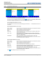
Screens during a recording
normal recording
measurement series completed for 71 %
trigger recording
trigger buffer not filled
trigger recording
trigger buffer full
waiting for trigger event
During cyclic recording the key
recording cycle.
6.8.
is occupied with „C-Stop“. Press this key to terminate the
Present Measurement Series
Recorded measurement series can be presented and analysed in different ways. Highlight the item
„Memory“ in the main menu and then press
:
Use the available functions to present a recorded measurement series:
© Hydrotechnik GmbH • All rights reserved
Rev. 1.5 / 120816 english
Page 36 of 45
MultiSystem 4010
Operating Instructions
Meas. series x
Highlight the desired measurement series and press
. Use
to scroll through the pages of the list. Press
to sort the list:
Output
Graphic y=f(t)
Table
Statistics
Channels/Present.
Type scaling
to
shows the measurement series selected for presentation; press
select a different one:
/
Highlight a sort option (numerical, alphabetical, recording time) and press
.
select one of three ways to present the data:
the measuring data will be presented as line diagram over the time
the measuring data will be presented as a table
statistical information on the measurement series will be displayed
here you may select the channels of the measurement series that shall
be presented and setup the presentation
select between automatic and manual scaling; at manual scaling you may
enter a range for each channel that shall be presented:
put the option „Type scaling“ to „Manual“, highlight the option „Scaling“
and press
; highlight a channel, press
and input the start and end
value of the data range that shall be presented
to define the scaling range for the selected channel
press
to do this for all channels; press
to select
automatically, or
between „MINMAX“ (the scaling range will be read out of the
measurement data) and „GRAPHIC“ (the scaling defined in the display
menu will be used); confirm the scaling with
© Hydrotechnik GmbH • All rights reserved
Rev. 1.5 / 120816 english
Page 37 of 45
MultiSystem 4010
Operating Instructions
Range
here you may do a time based selection of the measuring data; set the
option from „Total“ to „Clipping“:
enter the values for „from“ and „to“; then only the defined time range will
be presented
Press
to present the selected measurement data or
to close the menu.
Information
The definition of a scaling and/or time range does not influence
the measurement series. All values will remain there unchanged.
6.8.1.
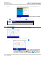
Graphical presentation
After pressing
the presentation will be calculated and then displayed:
Here you may use two functions to modify the presentation:
Zoom+
enlarges an area of the line diagram; press
:
a rectangle is shown in the center of the diagram; this shows the area that will be
enlarged; since
is occupied with the function „POS“ you may use the arrow
keys to shift the rectangle; then press
to switch to „SIZE“; now you may use
to apply the zoom:
the arrow keys to change the size of the rectangle; press
© Hydrotechnik GmbH • All rights reserved
Rev. 1.5 / 120816 english
Page 38 of 45
MultiSystem 4010
Operating Instructions
the desired area has been enlarged, you may now continue to zoom in or out
switched the scaling of the Y-axis between the shown channels
Y-scaling
Press
6.8.2.
to close the presentation.
Table presentation
After pressing
the table will be calculated and then presented:
Here you can see the measured values as a table. This will always contain eleven lines, the first and
the last measured value and nine interim values.
If you want to analyse the measured data, you should press
, highlight a line and press
. Then
the table will be calculated with the highlighted line, the line below and nine new interim values. That
can be repeated until the desired measured values are displayed. Press
to return to the initial
to close the presentation.
table. Press
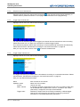
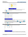
6.8.3.
Statistical data presentation
After pressing
the presentation will be calculated and then displayed:
For all channels you can see the minimal, maximal and arithmetic mean value. If a certain range is
selected in the menu “Presentation – Complexity“, the calculated values will change correspondingly.
© Hydrotechnik GmbH • All rights reserved
Rev. 1.5 / 120816 english
Page 39 of 45
MultiSystem 4010
Operating Instructions
Press
6.8.4.
to close the presentation.
Show information on measuring series
Press
to display information on the measuring series selected for presentation:
Here you can see the available information on the measuring series. The trigger time shows, how
much time expired after starting the recording before the trigger event happened. Press
to close
the information screen.
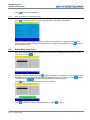
6.9.
Delete Measuring Series
Recorded measuring series can be deleted from the instrument. Highlight the item „Memory“ in the
main menu and press
:
Highlight a measuring series and press
to select / de-select it for deletion. A green check-mark will
be displayed left of the item. Select all measuring series that you want to delete, or press
to select
/ de-select all. Use
to scroll through the pages with measuring series.
Press
after selecting all measuring series to be deleted:
Press
to delete the selected measuring series, or press
© Hydrotechnik GmbH • All rights reserved
Rev. 1.5 / 120816 english
to abort.
Page 40 of 45
MultiSystem 4010
Operating Instructions
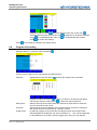
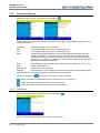
6.10.
Instrument Settings
Highlight the item „Device“ in the main menu and press
:
These are the two screens with basic device settings. Press
contain these options:
to toggle between both pages. They
Language
Date
Time
ISDS
operation language of the instrument
current date, used in the names of measuring series
current time, used in the names of measuring series
enables the automatic detection of sensors with Hydrotechnik ISDS; this option
should be enabled if you use such sensors; if you want to use ISDS sensor for
unusual purposes (e.g. pressure sensors to measure force), you should disable
this option; if you select “Yes preferred”, detected ISDS sensors will be selected for
display and recording automatically
Units
select between metric (SI) and anglo-american (US) unit system (e.g. bar – psi)
Filter
enable / disable filtering
Filter settings
see section 6.10.2 on page 42
Company
enter the name of your company; this will be saved together with measuring data
Baud rate RS232 select the transmission speed of the RS 232 interface
Confirm the settings with
. Use three function keys to open submenus:
dialog to set the CAN parameters (option, see section 6.10.1 on page 41)
further instrument settings (see section 6.10.3 on page 43)
information on the instrument (see section 6.10.4 on page 44)
6.10.1.
CAN settings
Open the submenu „Device“ from the main menu and press
:
Here you may set the parameters of the optional CAN function:
© Hydrotechnik GmbH • All rights reserved
Rev. 1.5 / 120816 english
Page 41 of 45
MultiSystem 4010
Operating Instructions
Baud rate CAN
6.10.2.
CAN Power
select the data transmission speed of the CAN bus; this must be identic for all
participants, otherwise communication will not be possible
select whether a supply power shall be emitted via the CAN interface
CANopen device
highlight this line and press
to send the start command into the CAN bus
Filter settings
Highlight the item „Filter settings“ in the device menu and press
:
Here you may use several software filters:
Filter for analog input channels (AD-channels)
The analog input channels are scanned with 1 ms. With the software filter mean values can be
calculated from several measured values to smooth the input signal. You may select between “1 ms”
(no smoothing) and “2/4/8/16 ms” (mean value caculation from 2/4/8/18 measured values). At “16 ms”
the instrument will deliver a new measured value each 16 ms.
Filter for frequency input channels
Information
The parameters for the combined input channel Ch4 will
only be displayed if it is programmed as frequency input
channel.
You may define two parameters for each frequency input channel:
Gate time
a new measured value will not be accepted until the gate time expired; enter a
multiple og 10 ms
Lowest frequency select the lowest frequency that shall be measured; this influences the behavior of
the instrument, when the measured value „Zero“ is displayed
Example
a lowest frequency of „0.25 Hz“ is defined and the measured object (e.g. a turbine
flow meter) stops running; this would have to be displayed as a measured value of
„0.00“; since the instrument is requested to measure down to 0.25 Hz, it will wait
four seconds for a new measured value, until “0.00” is displayed
In this case you should use a lowest frequency of 10 or 100 Hz, then the stopping
of the turbine will be displayed after 0.1 or 0.01 seconds.
Confirm the settings with
© Hydrotechnik GmbH • All rights reserved
Rev. 1.5 / 120816 english
.
Page 42 of 45
MultiSystem 4010
Operating Instructions
6.10.3.
Setup of the instrument
Attention
Possible loss of data!
All measuring data and possible customer-specific settings (e.g.
linearisation tables) will get lost by formatting the internal storage
medium. These data cannot be restored.
Open the submenu „Device“ and press
:
Hier sind grundlegende Funktionen enthalten:
Speichermedium
zeigt Art und Größe des im Messgerät enthaltenen Speichermediums;
während diese Option markiert ist, ist
mit dem Befehl „FORMAT“
belegt; drücken Sie diese Taste, um das Speichermedium zu formatieren:
Date
to format the storage medium, or
to abort the formatting;
Press
during the formatting, all data contained on the medium (e.g. measured
values) will be deleted irretrievably.
enter an interval after that you want to be reminded for a required
calibration of the instrument; this selection can only be done once and
cannot be changed later
shows the date of the next required calibration
Confirm the settings with
.
Interval
© Hydrotechnik GmbH • All rights reserved
Rev. 1.5 / 120816 english
Page 43 of 45
MultiSystem 4010
Operating Instructions
6.10.4.
Information on the instrument
Open the submenu „Device“ and press
:
Here you can see information on the software and hardware of your instrument. Open this submenu
when you contact the Hydrotechnik customer support. They will ask for this information.
Press
to close the screen.
7.
Cleaning and Maintenance
7.1.
Cleaning
Attention
Damage to the instrument is possible!
Switch the instrument off and cut-off the power supply BEFORE
starting to clean. This prevents the risk of a short-circuit, and thereby
possible damage to the device.
Attention
Damage to the instrument is possible!
Do NOT use any aggressive cleaning materials, solvents, benzin or
similar chemicals when cleaning the device. This prevents the risk of
damage to the casing and/or dulling the display.
If the casing becomes dirty, wipe it with soft, slightly damp cloth. Any ingrained dirt can be removed
with a mild household cleaning product.
© Hydrotechnik GmbH • All rights reserved
Rev. 1.5 / 120816 english
Page 44 of 45
MultiSystem 4010
Operating Instructions
7.2.
Calibration • Maintenance • Repair
Attention
Possible loss of data!
The internal memory and the storage medium can be deleted during
calibration and repair. All measuring data and customer-specific
parameters will be lost irretrievably!
This device works maintenance-free. However it is essential to recalibrate it regularly. If the device is
in continuous use, we recommend a recalibration every 2 years. Hydrotechnik runs an efficient
calibration laboratory accredited by the DAkks, where measuring instrument and sensors (even from
third parties) can be checked and calibrated precisely.
In case of a repair you should contact our customer service department. It is very helpful if you have
the following information on hand. Please add this information in written to your instrument if you send
it to us:
•
•
•
•
Complete address information (company, department, contact person, address, phone and fax
number, eMail address)
Rejected part (instrument, sensor, cable, power pack)
In the case of communication problems with your PC: used PC (CPU, RAM, HDD), operating
system (e.g. Windows 95/98/SE/2000/NT/XP/Vista/7, others), HYDROcom software version
Fault description (leave the settings at the instrument like at the time of the error; describe your
measuring task, sensor connection, device settings: like e.g. recording parameters, trigger, number
of collected measured values, …)
Address of the Hydrotechnik Customer Support
Hydrotechnik GmbH
Holzheimer Straße 94-96 • D-65549 Limburg
Tel.: 06431 – 4004 0 • Fax: 06431 – 45308
E-Mail: [email protected] • Internet: www.hydrotechnik.com
© Hydrotechnik GmbH • All rights reserved
Rev. 1.5 / 120816 english
Page 45 of 45