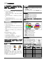
1
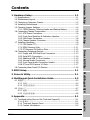
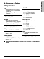
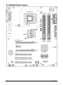
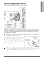
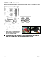
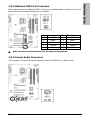
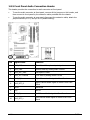
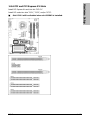
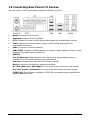
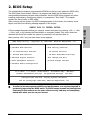
Hardware Setup
BIOS Setup
Driver & Utility
Motherboard
Socket 775
PCI Express
FSB1066
Dual DDR2 667
Gigabit LAN
4x SATA 3Gb/s
7.1 Channel HD Audio
Appendix
Intel Core 2 Duo, Pentium D,
Pentium 4, Celeron D
Multilingual QIG
IL9 Pro
Intel 945P / ICH7
IL9 Pro
User’s Manual
English + Multilingual QIG
1st Edition, October 2006
Copyright and Warranty Notice
The information in this document is subject to change without notice and does not represent a
commitment on part of the vendor, who assumes no liability or responsibility for any errors that may
appear in this manual.
No warranty or representation, either expressed or implied, is made with respect to the quality,
accuracy or fitness for any particular part of this document. In no event shall the manufacturer be
liable for direct, indirect, special, incidental or consequential damages arising from any defect or
error in this manual or product.
Product names appearing in this manual are for identification purpose only and trademarks and
product names or brand names appearing in this document are the property of their respective
owners.
This document contains materials protected under International Copyright Laws. All rights reserved.
No part of this manual may be reproduced, transmitted or transcribed without the expressed written
permission of the manufacturer and authors of this manual.
If you do not properly set the motherboard settings, causing the motherboard to malfunction or fail,
we cannot guarantee any responsibility.
ii
IL9 Pro
Hardware Setup
Contents
1. Hardware Setup ............................................................... 1-1
1.1
1.2
1.3
1.4
1.5
1.7
1.9
Driver & Utility
1.8
BIOS Setup
1.6
Specifications ..............................................................................1-1
Motherboard Layout.....................................................................1-2
Choosing a Computer Chassis .......................................................1-3
Installing Motherboard .................................................................1-3
Checking Jumper Settings ............................................................1-4
1.5.1 CMOS Memory Clearing Header and Backup Battery ..............1-4
Connecting Chassis Components...................................................1-6
1.6.1 ATX Power Connectors ........................................................1-6
1.6.2 Front Panel Switches & Indicators Headers............................1-7
1.6.3 FAN Power Connectors ........................................................1-8
1.6.4 Chassis Speaker Connector ..................................................1-8
Installing Hardware......................................................................1-9
1.7.1 CPU Socket 775 ..................................................................1-9
1.7.2 DDR2 Memory Slots .......................................................... 1-11
1.7.3 PCI Express X16 Add-on Slots ............................................ 1-12
Connecting Peripheral Devices .................................................... 1-13
1.8.1 Floppy and IDE Disk Drive Connectors ................................ 1-13
1.8.2 Serial ATA Connectors ....................................................... 1-14
1.8.3 Additional USB 2.0 Port Headers......................................... 1-15
1.8.4 Internal Audio Connectors.................................................. 1-15
1.8.5 Front Panel Audio Connection Header ................................. 1-16
1.8.6 PCI and PCI Express X1 Slots ............................................. 1-17
Connecting Rear Panel I/O Devices ............................................. 1-18
2. BIOS Setup....................................................................... 2-1
Multilingual QIG
3. Driver & Utility ................................................................. 3-1
4. Multilingual Quick Installation Guide .............................. 4-3
4.1 繁體中文 ....................................................................................4-3
4.1.1 規格 ..................................................................................4-3
4.1.2 快速安裝指南 .....................................................................4-4
4.2 简体中文 ....................................................................................4-7
4.2.1 规格 ..................................................................................4-7
4.2.2 快速安装指南 .....................................................................4-8
5. Appendix .......................................................................... 5-1
IL9 Pro
Appendix
5.1 Troubleshooting (How to Get Technical Support?) ..........................5-1
5.1.1 Q & A .................................................................................5-1
5.1.2 Technical Support Form ......................................................5-4
5.1.3 Contact Information ............................................................5-5
iii
iv
IL9 Pro
Hardware Setup
1. Hardware Setup
1.1 Specifications
• 3x PCI
CPU
• Support Intel Core 2 Duo, Pentium D,
Pentium 4, Celeron D Processor with
1066MHz FSB
• Supports Intel Hyper-Threading
Technology
Internal I/O Connectors
• 1x Floppy port
• 1x ATA 100 IDE connector
• 4x SATA 3Gb/s connectors
• 2x USB 2.0 headers
Chipset
• Intel 945P / ICH7
Memory
• 1x FP-Audio header
• 1x CD-In connector
Rear Panel I/O
• 4x 240-pin DIMM slots support
maximum memory capacity up to 4GB
• 1x PS/2 Keyboard connector
• Supports Dual Channel DDR2 667
Un-buffered Non-ECC memory
• 1x COM port
LAN
• Onboard 10/100/1000M LAN
Audio
• Onboard 7.1 CH HD Audio CODEC
Serial ATA
• 4x SATA 3Gb/s
Expansion Slots
• 1x PCI-E X16
• 1x PCI-E X16 (PCI-E X4 bandwidth)
• 1x PS/2 Mouse connector
• 1x LPT port
• 4x USB 2.0 connectors
• 1x RJ-45 Gigabit LAN connector
• 1x 7.1CH Audio Connector
• 1x S/PDIF Out
RoHS
• 100% Lead-free process and RoHS
compliant
Miscellaneous
• ATX form factor (305mm x 244mm)
• 1x PCI-E X1
※
Specifications and information contained herein are subject to change without
notice.
IL9 Pro
1-1
1.2 Motherboard Layout
1-2
IL9 Pro
•
Choose a chassis big enough to install this motherboard.
•
As some features for this motherboard are implemented by cabling connectors on the
motherboard to indicators and switches or buttons on the chassis, make sure your chassis
supports all the features required.
•
If there is possibility of adopting some more hard drives, make sure your chassis has
sufficient power and space for them.
•
Most chassis have alternatives for I/O shield located at the rear panel. Make sure the I/O
shield of the chassis matches the I/O port configuration of this motherboard. You can find
an I/O shield specifically designed for this motherboard in its package.
1.4 Installing Motherboard
Most computer chassis have a base with many
mounting holes to allow the motherboard to be
securely attached, and at the same time, prevent
the system from short circuits. There are two
ways to attach the motherboard to the chassis
base: (1) with studs, or (2) with spacers.
Basically, the best way to attach the board is
with studs. Only if you are unable to do this
should you attach the board with spacers. Line
up the holes on the board with the mounting holes on the chassis. If the holes line up and there
are screw holes, you can attach the board with studs. If the holes line up and there are only
slots, you can only attach with spacers. Take the tip of the spacers and insert them into the
slots. After doing this to all the slots, you can slide the board into position aligned with slots.
After the board has been positioned, check to make sure everything is OK before putting the
chassis back on.
※
Always power off the computer and unplug the AC power cord before adding or
removing any peripheral or component. Failing to so may cause severe damage
to your motherboard and/or peripherals. Plug in the AC power cord only after
you have carefully checked everything.
Locate all the screw holes on the
motherboard and the chassis base.
2.
Place all the studs or spacers needed on
the chassis base and have them tightened.
3.
Face the motherboard’s I/O ports toward
the chassis’s rear panel.
4.
Line up all the motherboard’s screw holes
with those studs or spacers on the chassis.
5.
Install the motherboard with screws and
have them tightened.
※
To prevent shorting the PCB circuit,
please REMOVE the metal studs or
spacers if they are already fastened
on the chassis base and are without
mounting-holes on the motherboard
to align with.
IL9 Pro
Face the chassis’s rear panel.
To install this motherboard:
1.
1-3
Hardware Setup
1.3 Choosing a Computer Chassis
1.5 Checking Jumper Settings
•
•
For a 2-pin jumper, plug the
jumper cap on both pins will
make it CLOSE (SHORT).
Remove the jumper cap, or
plug it on either pin
(reserved for future use) will
leave it at OPEN position.
SHORT
OPEN
OPEN
Pin 1~2 SHORT
Pin 2~3 SHORT
For 3-pin jumper, pin 1~2 or pin 2~3 can be
shorted by plugging the jumper cap in.
1.5.1 CMOS Memory Clearing Header and Backup Battery
The time to clear the CMOS memory occurs when (a)
the CMOS data becomes corrupted, (b) you forgot the
supervisor or user password preset in the BIOS menu,
(c) you are unable to boot-up the system because the
CPU ratio/clock was incorrectly set in the BIOS menu,
or (d) whenever there is modification on the CPU or
memory modules.
This header uses a jumper cap to clear the CMOS
memory and have it reconfigured to the default values
stored in BIOS.
•
Pins 2 and 3 shorted
(Default): Normal
operation.
•
Pins 1 and 2 shorted:
Clear CMOS memory.
To clear the CMOS memory and load in the default values:
1.
Power off the system.
2.
Set pin 1 and pin 2 shorted by the jumper cap. Wait for a few seconds. Set the jumper
cap back to its default settings --- pin 2 and pin 3 shorted.
3.
Power on the system.
4.
For incorrect CPU ratio/clock settings in the BIOS, press <Del> key to enter the BIOS
setup menu right after powering on system.
5.
Set the CPU operating speed back to its default or an appropriate value.
6.
Save and exit the BIOS setup menu.
1-4
IL9 Pro
An onboard battery saves the CMOS memory to keep the BIOS information stays on even after
disconnected your system with power source. Nevertheless, this backup battery exhausts after
some five years. Once the error message like “CMOS BATTERY HAS FAILED” or “CMOS
checksum error” displays on monitor, this backup battery is no longer functional and has to
be renewed.
To renew the backup battery:
1.
Power off the system and disconnect with AC power source.
2.
Remove the exhausted battery.
3.
Insert a new CR2032 or equivalent battery. Pay attention to its polarity. The “+” side is its
positive polarity.
4.
Connect AC power source and power on the system.
5.
Enter the BIOS setup menu. Reconfigure the setup parameters if necessary.
CAUTION:
※
Danger of explosion may arise if the battery is incorrectly renewed.
※
Renew only with the same or equivalent type recommended by the battery
manufacturer.
※
Dispose of used batteries according to the battery manufacturer’s instructions.
IL9 Pro
1-5
Hardware Setup
CMOS Backup Battery:
1.6 Connecting Chassis Components
1.6.1 ATX Power Connectors
These connectors provide the connection from an ATX power supply. As the plugs from the
power supply fit in only one orientation, find the correct one and push firmly down into these
connectors.
ATX 24-Pin Power Connector:
The power supply with 20-pin or 24-pin cables can both be connected to this 24-pin connector.
Connect from pin-1 for either type. However, a 20-pin power supply may cause the system
unstable or even unbootable for the sake of insufficient electricity. A minimum power of 300W
or higher is recommended.
ATX 12V 4-Pin Power Connector:
This connector supplies power to CPU. The system will not start without connecting power to
this one.
Auxiliary 12V Power Connector:
This connector provides an auxiliary power source for devices added on PCI
Express slots.
1-6
IL9 Pro
This header is used for connecting switches and LED indicators on the chassis front panel.
Watch the power LED pin position and orientation. The mark “+” align to the pin in the figure
below stands for positive polarity for the LED connection. Please pay attention when connecting
these headers. A wrong orientation will only cause the LED not lighting, but a wrong connection
of the switches could cause system malfunction.
IL9 Pro
Pin
Definition
Pin
Definition
1
HD LED +
2
Message LED +
3
HD LED -
4
Message LED -
5
RESET
6
Power Switch
7
RESET
8
Power Switch
9
Reserved
1-7
Hardware Setup
1.6.2 Front Panel Switches & Indicators Headers
1.6.3 FAN Power Connectors
These connectors each provide power to the cooling fans installed in your system.
•
CPUFAN1: CPU Fan Power Connector
•
SYSFAN2~3: System Fan Power Connector
※
These fan connectors are not jumpers. DO NOT place jumper caps on these
connectors.
1.6.4 Chassis Speaker Connector
This header provides the connection to chassis speaker.
1-8
IL9 Pro
Hardware Setup
1.7 Installing Hardware
※
DO NOT scratch the motherboard when installing hardware. An accidentally
scratch of a tiny surface-mount component may seriously damage the
motherboard.
※
In order to protect the contact pins, please pay attention to these notices:
1. A maximum 20 cycles of CPU installation is recommended.
2. Never touch the contact pins with fingers or any object.
3. Always put on the cap when the CPU is not in use.
1.7.1 CPU Socket 775
※
The installation procedures vary with different types of CPU fan-and-heatsink
assembly. The one shown here is served for demo only. For detailed
information on how to install the one you bought, refer to its installation
guidelines.
1. Place the board so as to let the
lever-hook of the socket is on your left side.
Use your left thumb and forefinger to hold
the lever hook, pull it away from the retention
tab. Rotate the lever to fully open position.
2. Use your right-thumb to raise the load
plate. Lift it up to fully open position.
IL9 Pro
3. Use your right thumb and forefinger to
grasp the CPU package. Be sure to grasp on
the edge of the substrate, and face the Pin-1
indicator toward the bottom-left side. Aim at
the socket and place the CPU package
vertical down into the socket.
4. Visually inspect if the CPU is seated well
into the socket. The alignment key must be
located in the notch of package.
1-9
5. Use your left hand to hold the load plate,
and use your right thumb to peel the cap off.
8. Place the heatsink and fan assembly onto
the socket. Align the four fasteners toward
the four mounting holes on the motherboard.
The cap plays an important role in
protecting contact pins. In order to
prevent bent pin, PUT ON the cap after
operation or testing.
9. Press each of the four fasteners down
into the mounting holes. Rotate the fastener
clock-wise to lock the heatsink and fan
assembly into position.
6. Lower the plate onto the CPU package.
Engage the load lever while gently pressing
down the load plate.
10. Attach the four-pin power plug from the
heatsink and fan assembly to the CPU FAN
connector.
7. Secure the lever with the hook under
retention tab.
※
1-10
A higher fan speed will be helpful for better airflow and heat-dissipation.
Nevertheless, stay alert to touch any heatsink since the high temperature
generated by the working system is still possible.
IL9 Pro
Hardware Setup
1.7.2 DDR2 Memory Slots
•
To reach the optimum performance in dual-channel configurations, install identical DDR2
DIMM pairs for each channel.
•
Install DIMMs with the same CAS latency. To reach the optimum compatibility, obtain
memory modules from the same vendor.
※
Usually there is no hardware or BIOS setup required after adding or removing
memory modules, but you will have to clear the CMOS memory first if any
memory module related problem occurs.
To install system memory:
1.
Power off the computer and unplug the
AC power cord before installing or
removing memory modules.
2.
Locate the DIMM slot on the board.
3.
Hold two edges of the DIMM module
carefully, keep away from touching its
connectors.
4.
Align the notch key on the module with
the rib on the slot.
5.
Firmly press the module into the slots until the ejector tabs at both sides of the slot
automatically snap into the mounting notch. Do not force the DIMM module in with extra
force as the DIMM module only fits in one direction.
6.
To remove the DIMM modules, push the two ejector tabs on the slot outward
simultaneously, and then pull out the DIMM module.
※
Static electricity can damage the electronic components of the computer or
optional boards. Before starting these procedures, ensure that you are
discharged of static electricity by touching a grounded metal object briefly.
IL9 Pro
1-11
1.7.3 PCI Express X16 Add-on Slots
These slots support the connections of graphics cards that comply with PCI Express
specifications. This motherboard provides dual PCI-Express X16 slots for one or two graphics
cards installation:
One PCIE graphics card installation (Normal Mode):
Install one PCIE graphics card into [Master]
slot (the PCIEX1 slot on this motherboard).
Two PCIE graphics cards installation (CrossFire Mode):
Install one CrossFire™ Edition graphics card
into [Master] slot (the PCIEX1 slot on this
motherboard), and one CrossFire™ Compatible
graphics card into [Slave] slot (the PCIEX2
slot on this motherboard).
※
The ATI CrossFire™ technology
currently supports the Microsoft
Windows XP with Service Pack 2
only.
※
Slot PCI-E1 will be disabled when
slot PCIEX2 is installed.
1-12
IL9 Pro
Hardware Setup
1.8 Connecting Peripheral Devices
1.8.1 Floppy and IDE Disk Drive Connectors
The FDC1 connector connects up to two floppy drives with a 34-wire, 2-connector floppy cable.
Connect the single end at the longer length of ribbon cable to the FDC1 on the board, the two
connectors on the other end to the floppy disk drives connector. Generally you need only one
floppy disk drive in your system.
※
The red line on the ribbon cable must be aligned with pin-1 on both the FDC1
port and the floppy connector.
Each of the IDE port connects up to two IDE drives
at Ultra ATA/100 mode by one 40-pin, 80-conductor,
and 3-connector Ultra ATA/66 ribbon cables.
Connect the single end (blue connector) at the longer
length of ribbon cable to the IDE port of this board,
the other two ends (gray and black connector) at the
shorter length of the ribbon cable to the connectors
of your hard drives.
※
Make sure to configure the “Master” and “Slave” relation before connecting
two drives by one single ribbon cable. The red line on the ribbon cable must be
aligned with pin-1 on both the IDE port and the hard-drive connector.
IL9 Pro
1-13
1.8.2 Serial ATA Connectors
Each SATA connector serves as one single channel to connect one SATA device by SATA cable.
To connect SATA device:
1.
Attach either end of the signal cable
to the SATA connector on
motherboard. Attach the other end to
SATA device.
2.
Attach the SATA power cable to the
SATA device and connect the other
end from the power supply.
※
The motherboard in this illustration is served for DEMO only, may not be the
same type or model as the one described in this user’s manual.
1-14
IL9 Pro
Each header supports 2x additional USB 2.0 ports by connecting bracket or cable to the rear I/O
panel or the front-mounted USB ports of your chassis.
※
Pin
Pin Assignment
Pin
1
VCC
2
Pin Assignment
VCC
3
Data0 -
4
Data1 -
5
Data0 +
6
Data1 +
7
Ground
8
Ground
10
NC
Make sure the connecting cable bears the same pin assignment.
1.8.4 Internal Audio Connectors
This connector connects to the audio output of internal CD-ROM drive or add-on card.
IL9 Pro
1-15
Hardware Setup
1.8.3 Additional USB 2.0 Port Headers
1.8.5 Front Panel Audio Connection Header
This header provides the connection to audio connector at front panel.
•
To use the audio connector at front panel, remove all the jumpers on this header, and
then connect to front panel by the extension cable provided with the chassis.
•
To use the audio connector at rear panel, disconnect the extension cable, attach the
jumpers back at pin 5-6, and pin 9-10 (default setting).
Pin
Signal Name
Function
1
AUD_MIC
Front Panel Microphone input signal
2
AUD_GND
Ground used by Analog Audio Circuits
3
AUD_MIC_BIAS
Microphone Power
4
AUD_VCC Filtered
+5V used by Analog Audio Circuits
5
AUD_F_R
Right Channel audio signal to Front Panel
6
AUD_RET_R
Right Channel Audio signal to Return from Front
Panel
7
REVD
Reserved
8
Key
No Pin
9
AUD_F_L
Left Channel Audio signal to Front Panel
10
AUD_RET_L
Left Channel Audio signal to Return from Front
Panel
1-16
IL9 Pro
Hardware Setup
1.8.6 PCI and PCI Express X1 Slots
Install PCI Express X1 card into slot “PCI-E1”.
Install PCI cards into slots “PCI1”, “PCI2”, and/or “PCI3”.
※
Slot PCI-E1 will be disabled when slot PCIEX2 is installed.
IL9 Pro
1-17
1.9 Connecting Rear Panel I/O Devices
The rear I/O part of this motherboard provides the following I/O ports:
•
Mouse: Connects to PS/2 mouse.
•
Keyboard: Connects to PS/2 keyboard.
•
LPT1: Connects to printer or other devices that support this communication protocol.
•
COM1: Connects to external modem, mouse or other devices that support this
communication protocol.
•
LAN1: Connects to Local Area Network.
•
USB1/USB2: Connects to USB devices such as scanner, digital speakers, monitor, mouse,
keyboard, hub, digital camera, joystick etc.
•
AUDIO1:
Line-In/Surround: Either connects to the line out from external audio sources, or
connects to the surround left and surround right channel.
Line-Out: Connects to the front left and front right channel.
Mic-In: Connects to the plug from external microphone.
R.L./R.R. (Rear Left / Rear Right): Connects to the rear left and rear right channel.
Cen./Sub. (Center / Subwoofer): Connects to the center and subwoofer channel.
S/PDIF Out: This connector provides an S/PDIF-Out connection through optical fiber to
digital multimedia devices.
1-18
IL9 Pro
2. BIOS Setup
This motherboard provides a programmable EEPROM so that you can update the BIOS utility.
The BIOS (Basic Input/Output System) is a program that deals with the basic level of
communication between processor and peripherals. Use the BIOS Setup program only when
installing motherboard, reconfiguring system, or prompted to “Run Setup”. This chapter
explains the Setup Utility of BIOS utility.
After powering up the system, the BIOS message appears on the screen, the memory count
begins, and then the following message appears on the screen:
PRESS DEL TO ENTER SETUP
After pressing <Del> key, the main menu screen appears.
CMOS Setup Utility – Copyright (C) 1985-2004, American Megatrends, Inc.
► Standard BIOS Features
► BIOS Security Features
► Boot Configuration Features
Load Optimal Settings
► Advanced BIOS Features
Load Best Performance Settings
► Advanced Chipset Features
Save Changes and Exit
► Power Management Features
Discard Changes and Exit
► Hardware Health Configuration
+/-/:Value
Enter:Select
F1:General Help
EXC:Exit
:Move
F8:Best Performance Settings
F9:Optimized Settings
F10:Save
Configure Time and Date. Display System Informaton…
V02.58 (C)Copyright 1985-2004, American Megatrends, Inc.
※
In order to increase system stability and performance, our engineering staff is
constantly improving the BIOS menu. The BIOS setup screens and descriptions
illustrated in this manual are for your reference only, and may not completely
match with what you see on your screen.
IL9 Pro
2-1
BIOS Setup
If this message disappears before you respond, restart the system by pressing <Ctrl> + <Alt>
+ <Del> keys, or by pressing the Reset button on computer chassis. Only when these two
methods fair should you restart the system by powering it off and then back on.
2-2
IL9 Pro
3. Driver & Utility
The “Driver & Utility CD” that came packed with this motherboard contains drivers, utilities and
software applications required for its basic and advanced features.
Place the “Driver & Utility CD” into the CD-ROM drive in your system. The following installation
auto-run screen appears. If not, browse the root directory of the CD-ROM via the File Manager,
and double click the “AUTORUN” file.
Driver & Utility
•
[Drivers]: Click to enter the driver installation menu.
•
[Manual]: Click to enter the user’s manual menu.
•
[Utility]: Click to enter the utilities installation menu.
•
[
•
[
IL9 Pro
Browse CD]: Click to browse the contents of this “Driver & Utility CD”.
Close]: Click to exit this installation menu.
3-1
3-2
IL9 Pro
4. Multilingual Quick Installation Guide
4.1 繁體中文
4.1.1 規格
處理器
• 支援具備 1066MHz 前端匯流排的 Intel
Core 2 Duo, Pentium D, Pentium 4,
Celeron D 處理器
• 支援 Intel Hyper-Threading 技術
晶片組
• Intel 945P / ICH7
記憶體
內部輸入/輸出接頭
• 1 個軟碟埠
• 1 個 ATA 100 IDE 接頭
• 4 個 SATA 3Gb/s 接頭
• 2 個 USB 2.0 接頭
• 1 個 FP-Audio 接頭
• 1 個 CD-In 接頭
後面板輸入/輸出接頭
• 4 條 240 針腳 DIMM 插槽支援最大 4GB
記憶體容量
• 1 個 PS/2 鍵盤接頭
• 支援雙通道 DDR2 667 無緩衝非 ECC 記憶
體
• 1 個 COM 連接埠
網路
• 1 個 PS/2 滑鼠接頭
• 1 個 LPT 連接埠
• 4 個 USB 2.0 接頭
• 內建 10/100/1000M 網路控制器
• 1 個 RJ-45 Gigabit 網路接頭
• 1 個 7.1 聲道音效接頭
音效
• 支援 7.1 聲道 HD 音效
Serial ATA
擴充插槽
• 1 個 PCI-E X16 插槽
RoHS
• 100%無鉛處理與 RoHS 相容
其他
• ATX 主機板規格(305mm x 244mm)
• 1 個 PCI-E X16 插槽 (PCI-E X4 頻寬)
• 1 個 PCI-E X1 插槽
• 3 個 PCI 插槽
※
本手冊的規格與資訊若有變動,恕不另行通知。
IL9 Pro
4-3
Multilingual QIG
• 4 個 SATA 3Gb/s
• 1 個 S/PDIF 音源輸出接頭
4.1.2 快速安裝指南
本「快速安裝指南」僅包含安裝 abit 主機板時
所需的基本硬體資訊。詳細的操作方式,請參
閱完整的手冊版本。
硬體安裝注意事項
• 安裝機板或變換任何設定之前,請先關閉電源並拔
掉電源插頭。
• 從抗靜電袋中取出機板前,請先戴上靜電安全手
環,以確保自己已確實接地。
• 請握住機板的邊緣。請勿接觸機板上的任何元件。
• 請勿接觸模組及 IC 晶片
• 請將機板置於已接地的抗靜電平面上,或置於隨附
的抗靜電袋。
將機板安裝至機殼內
連接機殼元件
ATX 電源供應器:[ATXPWR1]、[ATX12V1]
• 將標準 ATX 電源供應器連接至 2x12 針腳的
[ATXPWR1] 插座。
• 將輔助電源連接至 2x2 針腳的 [ATX12V1] 插座。
風扇插座:
• [CPUFAN1]:CPU 冷卻風扇插座。
• [SYSFAN1]:系統冷卻風扇插座。
• [AUXFAN1]:輔助冷卻風扇插座。
• [NBFAN1]:北橋冷卻風扇插座。
這些風扇插座並不是跳線。請勿將跳線置於這些插座
上。
前面板插座:[FPIO1]
本主機板的電腦機殼應符合以下條件:
• 與本主機板的規格相容。
• 機殼上的指示燈及開關支援主機板上的連接線插
座。
• 能提供足夠的電力及空間,以容納所有您想安裝的
磁碟機。
• 背面的 I/O 必須配合主機板上的 I/O 連接埠及擴充
插槽。
要將主機板安裝至機殼,您應該:
• 將 I/O 連接埠的內部面向機殼的後面。
• [HLED]:連接至硬碟 LED 連接線。
• [RST]:連接至重新啟動開關連接線。
• [SPKR]:連接至系統喇叭連接線。
• 將螺絲孔置於主機板與機殼的底座。
• [SLED]:連接至暫停 LED 連接線。
• 將所需的銅柱或塑膠腳座置於機殼底座並鎖緊。
• [PWR]:連接至電源開關連接線。
• 將主機板上所有的螺絲孔與機殼上的銅柱或塑膠腳
• [PLED]:連接至電源 LED 連接線。
座對齊。
• 將螺絲孔鎖緊。
要避免造成 PCB 電路短路,請「移除」已安裝在機殼
底座上,及本主機板上沒有安裝孔可對齊的的金屬銅
柱及腳柱。
清除 CMOS 跳線
這個跳線是用來清除
CMOS 記憶體以便重
新 設 定 BIOS 的 內
容。如果 BIOS 設定
有誤導致主機板無法
運作,您可能需要清
除 CMOS 記憶體。
若要清除 CMOS 記憶體,拔除主機板上所有的電源
線,將跳線連接到標有「清除 CMOS」的設定數秒鐘,
然後再將跳線插回「一般」設定。插回所有電源並重
新啟動電源時,BIOS 內容將重新設定成預設值。
4-4
前面板音效接頭:[FP-AUDIO1]
本接頭提供前面板 HD (高品質) 音
效連接。若要連接 AC’97 音效編碼,
您必須在連接到前面板模組之前仔
細確認接頭的針腳配置。如果配置
錯誤可能導致主機板故障或損毀。
請勿將前面板模組上標示為「Ground」與「USB VCC」
的纜線連接到此接頭上標示為「AVCC」的第 4 針腳。
針腳
1
2
3
4
5
6
7
9
10
針腳定義
(HD AUDIO)
MIC2 L
AGND
MIC2 R
AVCC
FRO-R
MIC2_JD
F_IO_SEN
FRO-L
LINE2_JD
針腳
1
2
3
4
5
6
7
9
10
針腳定義
(AC’97 AUDIO)
MIC In
GND
MIC Power
NC
Line Out (R)
NC
NC
Line Out (L)
NC
IL9 Pro
附加的 USB 連接埠接頭:[FP-USB1]、[FP-USB2]
連接儲存裝置
除了位於 I/O 面板上的內建 USB 接頭外,您可透過帶
有支架的延長線,連接這些各有兩個附加 USB 連接埠
的接頭。
連接軟碟機:[FDC1]
針腳
針腳定義
針腳
1
VCC
2
VCC
3
負資料通道 0
4
負資料通道 1
5
正資料通道 0
6
正資料通道 1
7
接地
8
接地
10
不連接
連接 IDE 硬碟:[IDE1]、[IDE2]
接腳定義
附 加 的 IEEE1394 連 接 埠 接 頭 : [FP-1394-1] 、
[FP-1394-2]
除了位於 I/O 面板上的內建 IEEE1394 接頭外,您可透
過帶有支架的延長線,連接這些各有一個附加
IEEE1394 連接埠的接頭。
針腳
針腳定義
針腳
針腳定義
1
TPA0 +
2
TPA0 -
3
接地
4
接地
5
TPB0 +
6
TPB0 -
7
+12V
8
+12V
10
接地
連接序列 ATA 硬碟機:[SATA1] ~ [SATA4]
內部音源連接頭:[CD1]、[AUX1]
這些插座提供透過序列 ATA 連接
線,每個通道連接一台序列 ATA 裝
置。
這個連接頭可選擇內部光碟機或附加卡的
音源輸出。
背面板線路連接
安裝 CPU 和散熱片配件
將散熱片安裝到處理器上以後,請將散熱風扇的電源
連接到主機板上的 [CPUFAN1] 插座。
安裝記憶體模組
• Mouse:連接 PS/2 滑鼠。
• Keyboard:連接 PS/2 鍵盤。
• LPT1:連接印表機或其他支援平行通訊協定的裝
置。
• COM1:連接外接數據機、滑鼠或其他支援序列通
訊協定的裝置。
• OPT-IN1:本插座提供透過光纖連接到數位多媒體
裝置的 S/PDIF 輸入。
• OPT-OUT1:本插座提供透過光纖連接到數位多媒
體裝置的 S/PDIF 輸出。
• AUDIO1: 7.1 聲道音效輸入/輸出連接。
• IEEE1394:連接 IEEE1394 通訊協定裝置。
• LAN1:連接區域網路。
靜電可能會損壞電腦或選購機板的電子元件。請在開
始上述操作程序之前,先短暫觸摸接地的金屬物件,
以排除靜電。
IL9 Pro
• USB1/USB2:連接 USB 裝置,例如掃描器、數位
喇叭、顯示器、滑鼠、鍵盤、集線器、數位相機或
搖桿等。
4-5
Multilingual QIG
由於市面上有多種中央處理器 (Central Processing
Unit, CPU) 和專用的散熱片可供選擇,而安裝方式也
各有不同,請確實遵循所購買產品包裝中隨附的安裝
指示。CPU 是一種精密的電子裝置,運作時會散發大
量的熱能。請務必小心處理。
4-6
IL9 Pro
4.2 简体中文
4.2.1 规格
处理器
• 支持具备 1066MHz 前端总线的 Intel Core
2 Duo, Pentium D, Pentium 4, Celeron D
处理器
• 支持 Intel 超线程技术
芯片组
• Intel 945P / ICH7
内存
内部输入/输出接头
• 1 个软盘端口
• 1 个 ATA 100 IDE 接头
• 4 个 SATA 3Gb/s 接头
• 2 个 USB 2.0 接头
• 1 个 FP-Audio 接头
• 1 个 CD-In 接头
后面板输入/输出接头
• 4 条 240 针脚 DIMM 插槽支持最大 4GB
内存容量
• 支持双信道 DDR2 667 无缓冲非 ECC 内存
• 1 个 PS/2 键盘接头
• 1 个 PS/2 鼠标接头
• 1 个 COM 连接埠
• 1 个 LPT 连接埠
网络
• 内建 10/100/1000M 网络控制器
• 4 个 USB 2.0 接头
• 1 个 RJ-45 Gigabit 网络接头
音效
• 1 个 7.1 声道音效接头
• 支持 7.1 声道 HD 音效
串行 ATA
• 4 个 SATA 3Gb/s
扩充插槽
RoHS
• 100%无铅工艺,符合 RoHS 规范
其它
• ATX 主机板规格(305mm x 244mm)
• 1 个 PCI-E X16 插槽(PCI-E X4 频宽)
• 1 个 PCI-E X1 插槽
• 3 个 PCI 插槽
※
本手册的规格与信息若有变动,恕不另行通知。
IL9 Pro
4-7
Multilingual QIG
• 1 个 PCI-E X16 插槽
• 1 个 S/PDIF 音源输出接头
4.2.2 快速安装指南
本“快速安装指南”仅包含基本的硬件信息,
供您在安装 abit 主板时进行参考。如需了解高
级操作,请参阅其详细指南。
硬件设置注意事项
• 在安装主板或更改任何设置前,务必关闭电源并从
交流插座上拔掉电源线。
• 从防静电袋中取出主板前,应戴上静电安全腕带以
使您正确接地。
• 用手拿着主板的边缘。不要触摸主板上的任何元
件。
• 不要触摸模块触点和 IC 芯片。
• 将主板放在接地的防静电表面上或者放在主板附带
的防静电袋中。
连接底盘元件
ATX 电源:[ATXPWR1]、[ATX12V1]
• 将 标 准 的 ATX 电 源 连 接 到 2x12 针 脚 的
[ATXPWR1] 连接器。
• 将自备电源连接到 2x2 针脚的 [ATX12V1] 连接
器。
风扇连接器:
• [CPUFAN1]:CPU 冷却风扇连接器。
• [SYSFAN1]:系统冷却风扇连接器。
• [AUXFAN1]:辅助冷却风扇连接器。
• [NBFAN1]:北桥冷却风扇连接器。
这些风扇连接器不是跳线。不要将跳线帽插到这些连
接器上。
前面板连接器:[FPIO1]
将主板安装到底盘上
此主板的计算机底盘应符合下列条件:
• 支持此主板的外形尺寸。
• 支持主板上的所有线缆连接器,能够连接到底盘上
的指示灯和开关。
• 能够为您要安装的所有驱动装置提供充足的电源和
空间。
• 底盘后面板上的 I/O 模板与主板上的 I/O 端口和扩
展槽匹配。
• [HLED]:连接 HDD LED 电缆。
• [RST]:连接复位开关电缆。
要将主板安装到底盘上,您应该:
• [SPKR]:连接系统扬声器电缆。
• 使 I/O 端口一侧朝向底盘的后部。
• [SLED]:连接挂起 LED 电缆。
• 在主板和底盘上找到螺丝孔。
• [PWR]:连接电源开关电缆。
• 将所有销钉或柱杆放到底盘上,然后拧紧它们。
• [PLED]:连接电源 LED 电缆。
• 将底盘上的销钉或柱杆对准主板上的螺丝孔。
• 利用这些螺丝孔将主板固定在底盘上。
如果底盘上已经安装了金属销钉或柱杆,并且在主板
上没有它们的安装孔,为防止 PCB 短路,请“取下”
这些金属销钉或柱杆。
CMOS 清除跳线
此跳线用于清除
CMOS 存储器以重置
BIOS 内容。当 BIOS
设置不正确并导致主
板无法工作时,应清
除 CMOS 存储器。
请勿将前面板模块上标示为
「Ground」与「USB VCC」的缆线连接到此接头上
标示为「AVCC」的第 4 针脚。
针脚
正常
(默认)
清除 CMOS
要清除 CMOS 存储器,请断开主板上的所有电源线,
将跳线帽插到“清除 CMOS”位置上几秒钟,然后将
跳线帽插回“正常”位置。重新接通所有电源并启动
后,BIOS 内容将恢复成默认配置。
4-8
前面板音频接头:[FP-AUDIO1]
本接头提供前面板 HD (高品质) 音
效连接。若要连接 AC’97 音效编码,
您必须在连接到前面板模块之前仔
细确认接头的针脚配置。如果配置
错误可能导致主机板故障或损毁。
1
2
3
4
5
6
7
9
10
针脚定义
(HD AUDIO)
MIC2 L
AGND
MIC2 R
AVCC
FRO-R
MIC2_JD
F_IO_SEN
FRO-L
LINE2_JD
针脚
1
2
3
4
5
6
7
9
10
针脚定义
(AC’97 AUDIO)
MIC In
GND
MIC Power
NC
Line Out (R)
NC
NC
Line Out (L)
NC
IL9 Pro
附加的 USB 端口接头:[FP-USB1]、[FP-USB2]
连接存储设备
除了位于 I/O 面板上的板载 USB 连接器外,这些接头
可以通过带线卡的延长电缆分别提供两个附加的 USB
端口连接。
连接软盘驱动器:[FDC1]
针脚
针脚定义
针脚
1
VCC
2
VCC
3
负数据通道 0
4
负数据通道 1
5
正数据通道 0
6
正数据通道 1
7
接地
8
接地
10
无连接
连接 IDE 硬盘驱动器:[IDE1]、[IDE2]
针脚定义
附 加 的 IEEE1394 端 口 接 头 : [FP-1394-1] 、
[FP-1394-2]
除了位于 I/O 面板上的板载 IEEE1394 连接器外,这些
接头可以通过带线卡的延长电缆分别提供一个附加的
IEEE1394 端口连接。
针脚
针脚定义
针脚
针脚定义
1
TPA0 +
2
TPA0 -
3
接地
4
接地
5
TPB0 +
6
TPB0 -
7
+12V
8
+12V
10
接地
连接串行 ATA 硬盘驱动器:[SATA1] ~ [SATA4]
内部音频连接器:[CD1]、[AUX1]
这些连接器的作用在于利用串行
ATA 电缆在每个通道上连接一个串
行 ATA 设备。
此连接器用于从内部 CD-ROM 驱动器或扩
展卡的音频输出中选择音频。
后面板连接
安装 CPU 和过热降温装置
将过热降温装置安装到处理器上后,把 CPU 冷却风扇
的电源连接到主板上的 [CPUFAN1] 连接器。
安装内存模块
• Mouse:连接 PS/2 鼠标。
• Keyboard:连接 PS/2 键盘。
• LPT1:连接打印机或其它支持并行通信协议的设
备。
• COM1:连接外部调制解调器、鼠标或支持串行通
信协议的其它设备。
• OPT-IN1:此连接器通过光纤提供 S/PDIF 输入连
接,用于连接数码多媒体设备。
• OPT-OUT1:此连接器通过光纤提供 S/PDIF 输出
连接,用于连接数码多媒体设备。
• AUDIO1:7.1 声道音效输入/输出连接。
• IEEE1394:连接支持 IEEE1394 协议的设备。
• LAN1:连接到局域网。
静电可能会损坏计算机或板卡选件上的电子元件。在
开始上述操作之前,请触摸一下接地的金属物品,以
确保释放身上的静电。
IL9 Pro
• USB1/USB2:连接 USB 设备,如扫描仪、数码扬
声器、监视器、鼠标、键盘、集线器、数码相机、
操纵杆等。
4-9
Multilingual QIG
可供选择的中央处理单元 (CPU) 及其过热降温装置
有很多种,每一种的安装方式都不相同,因此请严格
按照产品包装中的安装说明进行操作。CPU 是一种精
密的电子设备,工作时会产生大量热量。操作时,务
请小心谨慎。
4-10
IL9 Pro
5. Appendix
5.1 Troubleshooting (How to Get Technical Support?)
5.1.1 Q & A
Q: Do I need to clear the CMOS before I use a new motherboard to assemble my
new computer system?
A: Yes, we highly recommend that you clear the CMOS before installing a new motherboard.
Please move the CMOS jumper from its default 2-3 position to 1-2 for a few seconds, and
then back. When you boot up your system for the first time, follow the instructions in the
user's manual to load the optimized defaults.
Q: If my system hangs when I update the BIOS or set the wrong CPU parameters,
what should I do?
A: Whenever you update the BIOS or if the system hangs due to wrong CPU parameters
setting, always clear CMOS jumper before booting up again.
Q: Why does the system fail to boot up again right after a mechanical power-off?
A: Please keep a 30-second interval between each mechanical power On/Off.
Q: Why does the system fail to boot up and nothing displays on the screen after I
did some over-clocking or non-standard settings inside the BIOS?
A: It should not cause hardware or permanent damage to motherboard when BIOS settings
were changed from default to over-clocking or non-standard status.
We suggest the following three troubleshooting methods to discharge CMOS data, recover
the hardware default status, and then making the motherboard work again. There is no
need to bother returning the motherboard to where you bought it from or go through an
RMA process.
Step 1.Switch off the power supply unit and then switch it on again after one minute. If
there is no power-switch on the power supply unit, disconnect its power cord for
one minute and then reconnect.
Press and hold the <Insert> key on the keyboard, and press the power-on button
to boot up system. If it works, release the <Insert> key and hit <Del> key to enter
the BIOS setup page to apply the correct settings.
If the situation remains the same, repeat the procedures in Step 1 for three times,
or try Step 2.
Step 2.Switch off the power supply unit or disconnect the power cord. Open the chassis
cover. Locate the CCMOS jumper near the button battery. Change the jumper
position from default 2-3 to 1-2 for one minute to discharge the CMOS data, and
then put it back to default 2-3 position.
Close the chassis and switch on the power supply unit or plug in the power cord.
Press the power-on button to boot up system. If it works, hit <Del> key to enter
the BIOS setup page to do the correct settings.
If the situation remains the same, try Step 3.
IL9 Pro
5-1
Appendix
Step 3.The same procedure as Step 2, but while discharging the CMOS data, pull out the
ATX power connectors from motherboard and remove the button battery during
CMOS discharge.
Q: How to get a quick response for my request on technical support?
A: Please carry out a simple troubleshooting before sending “Technical Support Form”:
System boot-up fails after the system had been assembled:
Check the motherboard’s supporting specifications first to see if all the key components
attached in your system can meet.
To do so, you may:
•
Remove all the unnecessary add-on devices (except the CPU, VGA card, DRAM, and
Power Supply), and then reboot.
•
If the trouble still exists, try another VGA card of different brand/model to see if the
system will start.
•
If the trouble still exists, try another memory module of different brand/model.
•
If the trouble still exists, try another CPU and Power Supply.
If the system runs successfully, shut it down and start re-installing the interface cards and
devices that were previously installed in the system. Re-install and start the system one at a
time until the system won’t start.
Malfunction in the OS:
If the system hangs after resuming from S3 or some testing program, if the CPU cannot be
recognized properly, if the display resolution mixed, or if a certain program cannot be
executed, etc, you may:
•
Upgrade the motherboard’s latest BIOS version.
•
Upgrade the add-on device’s latest driver version.
•
Check if there is any conflict in the “Control Panel/System Properties”.
Q: How to fill in the “Technical Support Form”?
A: To fill in this “Technical Support Form”, please refer to the following instructions:
5-2
•
Region: Type in your country name.
•
E-mail: Type in your contact E-mail information.
•
First name: Type in your first name.
•
Last name: Type in your last name.
•
Subject: Type in the model name and the problem of your motherboard.
Example 1: AA8XE and SCSI 29160 malfunction
Example 2: AA8XE boot fails, POST code AF
Example 3: AA8XE (system hang when S3 resume)
•
Motherboard: Type in the model name and revision number of your motherboard.
Example: AA8XE REV: 1.00
•
BIOS Version: Type in the BIOS version of your motherboard. (You can find it on the
screen during the POST sequence.)
•
CPU: Type in the brand name and the speed (MHz) of your CPU. (Illustrate the
over-clocking status if you had done so.)
Example: Intel 650 3.4GHz (OC FSB=220MHz)
•
Memory brand: Type in the brand and model name of your memory module.
Example: Memory brand: Kingston (KVR533D2N4/1G)
•
Memory size: Type in the size of your memory module.
Example: 512M* 4PCS
IL9 Pro
•
Memory configuration: Type in the memory configuration in BIOS setting.
Example: Memory Timing: 2.5-3-3-7 @533MHz
•
Graphics information: Note Graphics card’s brand, model and driver version
•
Graphics card: Type in the brand and model name of your graphics card.
Example: ATI RADEON X850 XT PE
•
Graphics driver version: Type in the driver version of your graphics card
Example: Catalyst 5.12V
•
Power supply maker: Type in the brand and model name of your power supply unit.
•
Power supply wattage: Type in the power wattage of your power supply unit.
•
Storage devices: Type in the brand and specifications of your HDD drive and quantity.
Specify if it was inserted on IDE (Master or Slave) or SATA ports, including the RAID
allocation status.
Example 1: WD Caviar WD600 60GB (on IDE2 master), Maxtor DiamondMax 10 SATA
300GB (on SATA 3)
Example 2: Maxtor DiamondMax 10 SATA 300GB *2 (on SATA 3, SATA 4 RAID 1)
•
Optical devices: Type in the brand and specifications of your optical drives and
quantity. Specify if it was inserted on IDE (Master or Slave) or SATA ports.
•
Other devices: Indicate which add-on cards or USB devices that you absolutely sure
are related to the problem. If you cannot identify the problem’s origin, indicate all the
add-on cards or USB devices inserted on your system.
Example: AHA 29160 (on PCI 2), Sandisk Cruzer mini 256MB USB Flash-disk.
•
Operating system: Indicate which OS and language version
Example: Microsoft Windows XP SP2, English version
Example: Microsoft Media Center Edition 2005, Korean version
•
Problem description: Describe the problem of your system configuration. Indicate
the steps to duplicate problem if possible.
See the next page for a blank Technical Support Form, or visit our website to fill in the
form on line (http://www.abit.com.tw/page/en/contact/technical.php).
Q. Is the motherboard dead? Do I need to return it to where I bought from or go
through an RMA process?
A: After you had gone through the troubleshooting procedures, yet the problem still exists, or
you find an evident damage on the motherboard. Please contact our RMA center.
(http://www2.abit.com.tw/page/en/contact/index.php?pFUN_KEY=18000&pTITLE_IMG)
Appendix
IL9 Pro
5-3
5.1.2 Technical Support Form
Region:
E-mail:
First name:
Last Name:
Subject:
Motherboard:
BIOS Version:
CPU:
Memory brand:
Memory size:
Memory configuration:
Graphics card:
Graphics driver version:
Power supply maker:
Power supply wattage:
Storage devices:
Optical devices:
Other devices:
Operating system:
Problem description:
5-4
IL9 Pro
5.1.3 Contact Information
Taiwan Head Office
Universal ABIT Co., Ltd.
No. 323, Yang Guang St., Neihu,
Taipei, 114, Taiwan
Tel: 886-2-8751-3380
Fax: 886-2-8751-3381
Sales: [email protected]
Austria, Czech, Romania, Bulgaria,
Slovakia, Croatia, Bosnia, Serbia,
Macedonia, Slovenia
Universal ABIT Austria Computer
GmbH
Schmalbachstrasse 5, A-2201 Gerasdorf /
Wien, Austria
Marketing: [email protected]
Tel: 43-1-7346709
Fax: 43-1-7346713
North America, South America
Website: http://www.abit-austria.at
Contact: [email protected]
Universal ABIT (USA) Corporation
2901 Bayview Drive,
Fremont, CA 94538, U.S.A.
Tel: 1-510-623-0500
Fax: 1-510-623-1092
Website: http://www.abit-usa.com
Latin America: [email protected]
RMA Center: http://rma.abit-usa.com
Shanghai
Universal ABIT (Shanghai) Co. Ltd.
FL 19 Xuhui Yuan BLOG NO.1089
ZhongShan s 2 RD, ShangHai 200030
The People's Republic of China
Tel: (86-21) 54102211
Fax: (86-21) 54104791
Website: http://www.abit.com.cn
UK, Ireland
Universal ABIT UK Corporation
Poland
Unit 3, 24-26 Boulton Road, Stevenage,
Herts SG1 4QX, UK
Universal ABIT Poland (Rep. office)
Tel: 44-1438-228888
Fax: 44-1438-226333
Tel: +48-71-718-12-39
Fax: +48-71-718-12-38
for technical support:
[email protected]
Contact: Grzegorz Morgiel
for RMA no direct technical support:
[email protected]
Tel: 44-1438-362088
Strzegomska 310/2, 54-432 Wroclaw
Turkey
Universal ABIT Turkey (Rep. office)
Tel: 90 532 211 6860
Germany and Benelux (Belgium,
Netherlands, Luxembourg), France, Italy,
Spain, Portugal, Greece, Denmark,
Norway, Sweden, Finland, Switzerland
Universal ABIT NL B.V.
Appendix
Jan van Riebeeckweg 15, 5928LG,
Venlo, The Netherlands
Tel: 31-77-3204428
Fax: 31-77-3204420
IL9 Pro
5-5
http://www.abit.com.tw
P/N: 4310-0000-50
Rev. 1.00