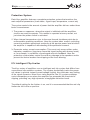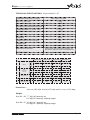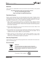
1
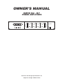
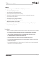
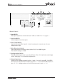
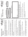
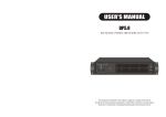
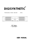
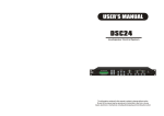
OWNER'S MANUAL
KRYO K4 - K7
POWER AMPLIFIERS
acoustics
OWNER'S MANUAL
KRYO K4 - K7
POWER AMPLIFIERS
Kryo K7
LIMIT
CH A
CH B
ON
LIMIT
PRO
PRO
TEMP
TEMP
SIG
SIG
8
8
0dB
POWER
0dB
STBY
Technical and design specifications are
subject to change without notice
Kryo
Series Power Amplifiers
acoustics
TO PREVENT ELECTRIC SHOCK, DO NOT
REMOVE TOP OR BOTTOM COVERS.
NO USER SERVICEABLE PARTS INSIDE.
REFER SERVICING TO QUALIFIED
SERVICE PERSONNEL. DISCONNECT
POWER CORD BEFORE REMOVING
REAR PANEL COVER TO ACCESS GAIN
SWITCH.
Shock Hazard - Do Not Enter
Choc Hasard - N*entrent
Schocke Hazard - Test Nicht
Betrete
Urto Hazard - Do Non Entrano
WARNING
TO REDUCE THE RISK OF ELECTRIC
SHOCK, DO NOT EXPOSE THIS
EQUIPMENT TO RAIN OR MOISTURE!
Magnetic Field
CAUTION: Do not locate sensitive high-gain equipment such as preamplifiers or tape decks
directly above or below this unit. Because this amplifier has a high power density, it has a
strong magnetic field which can induce hum into unshielded devices that are located nearby.
This field is strongest just above and below the unit. If an equipment rack is used, we
recommend locating the amplifier(s) at the bottom of the rack and the preamplifier or other
sensitive equipment at the top.
The lightning bolt triangle is
used alert the user to the risk
of electric shock
The exclamation point triangle is used
to alert the user to important operating
and/or maintenance instructions.
Printed on
recycled paper.
Page 3
Kryo
Series Power Amplifiers
acoustics
Features
Rugged, touring grade chassis. E.I.A. Standard 19" (48.3cm) rack-mountable.
Ultra compact and lightweight 2u design.
Super high frequency switch mode power supply.
Optional add on Modules extend operational capability.
Switchable (ICL) Intelligent Clip limiters prevent harmful signals from damaging loudspeakers.
Input link switch for linking channels.
Dual and Bridge modes for optimal load matching.
Switchable 30 or 50Hz Hi Pass filters on every channel.
Balanced XLR inputs with Speakon outputs.
Complete protection against shorted outputs, mismatched loads, overheating and DC input/output.
Three year warranty and guarantee.
Precautions
Although your amplifier is protected from external faults, the following safety precautions are recommended:
1. Do not change the position of the bridge mode switch unless the amplifier is switched off.
2. There are important differences between Dual, Link and Bridge modes. Please refer to page 9
for a detailed description of the different modes and there uses.
3. Switch off the amplifier or turn down the inputs before connecting to the in/out XLR's.
4. Do not short the ground lead of an output cable to the input signal ground. This will form a ground loop
and may cause oscillations.
5. Do not operate the amplifier from AC mains in excess of 10% variation above or below the selected line
voltage, and only at the specified line frequency.
Page 4
Kryo
Series Power Amplifiers
acoustics
Kryo K7
LIMIT
CH A
CH B
TEMP
POWER
SIG
SIG
0dB
8
8
4
ON
LIMIT
PRO
PRO
TEMP
3
0dB
3
STBY
4
2 1
Front Panel
1.Power Switch
Used to turn the amplifier on or off.
2.Power LED's
The top blue LED lights when the amplifier is switched on.
The lower amber LED lights when the amplifier is in stand-by mode and is
remotely activated via Ethernet.
3.Level Controls
Used to control CH A and B's output level.
4.Status LED's
SIG
When illuminated the signal LED's indicate an audio signal is present at the
channel's input.
TEMP
Indicates when temperature protection is active.
PRO
The protect LED's light up when the amplifier goes into protect mode.
See page 11.
LIMIT
The Limit LED's indicate when the ICL limiter is active. The limiter circuit
examines the audio output signal to prevent the amplifier from clipping.
See page 11.
Page 5
Kryo
Series Power Amplifiers
acoustics
3
2
LINK
CH-B
CH-B
1
2
IN
LINK
1
CH-A
IN
CH-A
GAIN (dB)
6
5
4
Rear Panel
1.Input XLR's
The input impedance of the balanced XLR's is 20KΩ. Pin 2 is signal +
2.Link Out XLR's
Linked outputs from the inputs.
3.Link / Dual Switch
Used to link input B to input A. In dual mode each channel uses its own
independent input.
4.Gain Selection Switch
The three position switches select either 26, 32 or 38dB of gain.
The default setting is 32dB.
5.Configuration Switch
The dip switches are used to set the Hi Pass filter, ICL clip limiter and bridge
mode. See page 7 for a detailed explanation.
6.Output Speakons
In dual or link modes connect to pins +1 and -1 on out A or out B. Out A/B is
also wired so that channel A outputs on pins +1, -1 and channel B outputs on
pins +2, -2. In bridge mode use out A/B and connect to pins +1, +2.
Page 6
Kryo
Series Power Amplifiers
acoustics
Installation and Operation
Configuration Switches
The amplifier has a set of mini dip switches on the rear panel. These switches
allow the activation of the Hi Pass filter and its frequency, the activation of the ICL
clip limiter and bridge mode. Any of these configurations can be activated in any
way.
The basic configurations are as follows:
Standard Configuration: the amplifier
works without Hi Pass subsonic filter,
Clip Limiter ICL enabled and no Bridge
mode.
Sub-sonic Filter Enabled: the amplifier
works with Hi Pass subsonic filter
(30Hz in this case), Clip Limiter ICL
enabled and no Bridge mode.
Bridge Mode: the amplifier works
without Hi Pass subsonic filter, Clip
Limiter ICL enabled and Bridge mode.
ICL Clip Limiter Disabled: the amplifier works without Hi Pass subsonic filter, Clip Limiter ICL disabled and no
Bridge mode.
Page 7
Kryo
Series Power Amplifiers
acoustics
LED Status
In the event of incorrect connection or a malfunction, the amplifier will activate one
or more of its LED's to warn about the problem.
SIG
TEMP PRO LIMIT
Correct function: SIG lights to indicate
a signal's presence.
SIG
TEMP PRO LIMIT
ICL: The Intelligent Clip Limiter is operating (see page 11).
SIG
TEMP PRO LIMIT
No Signal: No Input Signal is reaching
the amplifier.
SIG
TEMP PRO LIMIT
Overheating: The amplifier has reached the maximum operational temperature. Most common cause is: the normal air flow is blocked, accumulated
dirt, dust or object leaning against the
grill. Check and clean periodically.
SIG
TEMP PRO LIMIT
PRO: Several causes can trigger this
LED, refer to page 11 for more details.
Page 8
Kryo
Series Power Amplifiers
acoustics
System Connections
Dual Mode
In dual mode connect individual sources to inputs A and B and set the link / dual
switch to dual. Channel A's input will output from out A, channel B's input will
output from out B. Out A and out B use pins +1,-1 or you can connect to out A/B
with 4 core cable, where pins +1,-1 are for channel A and pins +2,-2 are for
channel B. This type of arrangement could be used for 2 way active speakers,
where channel A would be bass and channel B would be HF. If 4 core speaker
cable was used then the speaker would be connected from out A/B. Note, this
arrangement would only work if the speakers were wired pins +1,-1 to the
woofer and pins +2, -2 to the HF unit.
Link Mode
If the link / dual switch is set to link, then channels A and B will receive the
same signal. This mode is useful if you only have 1 input source but want to
feed both amplifier channels. Typical arrangements could be powering 2 speakers
from a mono output, in which case you would connect the mono source to input
A and set the link switch to link. The same signal will now appear at both out A
and Out B.
Bridge Mode
In bridge mode channels A and B are combined to form one channel. To enable
bridge mode set the dip switches to bridge and use input A. The link / dual switch
should be set to dual and use out A/B for the output. Connect to pins +1 and +2.
Pin +1 is signal +. Note that the minimum impedance in bridged mode is 4 ohms.
Page 9
Kryo
Series Power Amplifiers
acoustics
Dual Channel mode
Linked Inputs
Bridge Mode
Page 10
Kryo
Series Power Amplifiers
acoustics
Protection System
Each Kryo amplifier features a complete protection system that monitors the
main amplifier parameters (load status, signal input, temperature, current etc)
The system controls the amount of power that the amplifier delivers under three
basic circumstances.
1. The power on sequence, where the output is inhibited until the amplifiers
circuits are ready to operate. This routine is repeated at every restart, not
just when the power switch is activated.
2. When internal temperatures rise to the near thermal shutdown point due to
unfavourable operating conditions. Here the system takes control, restricting
current to maintain operational continuity at the precise power level at which
the amplifier is capable of withstanding at the particular moment.
3. Excessive mains current consumption. This event only occurs either under
laboratory conditions (long term sinusoidal signal testing with dummy loads)
or, for example, in conditions of prolonged acoustic feedback. Here the
protection system takes control to avoid any damage to the speakers and to
prevent the mains breaker from tripping or the fuses blowing.
ICL Intelligent Clip Limiter
The Kryo series of amplifiers use an intelligent anti clip system that differs from
conventional clip reduction systems. The system dynamically tracks the power
rail values to provide instant current/voltage limiting, this eliminates any limiting
of the signal dynamics. More like a valve amplifier, the ICL system maintains
sonic transparency even when the amplifier has exceeded the threshold of
clipping, providing very high dynamics at negligible distortion levels.
The default setting for the limiters is on, and it is recommended that the anti clip
limiters be left in the on position.
Page 11
Kryo
Series Power Amplifiers
acoustics
TECHNICAL SPECIFICATIONS
Kryo models K4 - K7
FREQUENCY RESPONSE ref.100W@8Ω
20Hz - 20kHz +/-0.25 dB
ref. 4Ω, 20Hz - 20KHz
<0.05%
S/N 20Hz-20kHz, ref full output
115 dB
THD
INTERMODULATION DISTORTION, SMPTE
PHASE RESPONSE
CROSSTALK
<0.05%
+/- 15 deg
@ 1 watt 20Hz - 20KHz
>75dB
20Hz - 20KHz
26/32/38 dB
VOLTAGE GAIN
60V/us
SLEW RATE
DAMPING FACTOR
>500
20Hz - 500Hz @ 8Ω
CONNECTORS
Input: balanced XLR Output: Speakon
2 Variable speed fans
COOLING
Full short circuit, open circuit, thermal, ultrasonic, and
RF protection, stable into reactive or mismatched loads
AMPLIFIER PROTECTION
220 - 240V AC 50/60 Hz
Impedance
VOLTAGE RANGE
Mode
Both
Channels
Driven
Bridge Mode
Kryo K4
Kryo K5
Kryo K6
Kryo K7
RMS per ch
RMS per ch
RMS per ch
RMS per ch
0.1%THD+N
0.1%THD+N
0.1%THD+N
0.1%THD+N
1kHz
1kHz
1kHz
1kHz
2
880
1190
1570
1950
4
575
790
1100
1380
8
325
460
630
810
4
1760
2380
3140
3900
1150
1580
Sensitivity @ 8Ω
2.6/1.3/0.6 V
3.0/1.5/0.8 V
Maximum Current Draw
@ 1/8 rated power
4A
4.8 A
Dimensions :
8
2200
3.6/1.8/0.9 V
6.2 A
2760
4.0/2.0/1.0 V
7.5 A
48.3 cm (19") wide, 8.9 cm (3.5") high and 31.0 cm (12.2") deep.
Weight:
Kryo K4 - K5: 7.7 Kg (16.9 pounds) net.
10.2 Kg (22.9 pounds) shipping weight.
Kryo K6 - K7 8.0 Kg (18.7 pounds) net.
10.5 Kg (23.1 pounds) shipping weight.
Page 12
Kryo
Series Power Amplifiers
acoustics
Service
This unit has very sophisticated circuitry and should only be serviced by a fully trained
technician.
To prevent electric shock, do not remove covers
No user serviceable parts inside
Refer servicing to a qualified technician
Worldwide Service
Service may be obtained from your local authorised service centre. To obtain service,
simply present your sales receipt as proof of purchase along with the defective unit to
an authorised service centre. They will handle the necessary paperwork and repair.
Remember to transport your unit in the original factory packaging.
1. When sending a Kryo Series product to an authorised service centre for service,
please write a detailed description of the fault and list any other equipment used in
conjunction with the faulty product. Send the fault description with the faulty product,
do not send it separately.
2. Ensure safe transportation of your unit to the authorised service centre. Ship it in the
original factory packaging if possible.
3. Do not ship the unit in any kind of rack. Ignoring this warning may result in extensive
damage to the unit and the equipment rack. Accessories are not needed. Do not
send the instruction manual, cables or any other hardware.
4. Before returning your faulty product for repair, please remember to get a return
authorisation number from the dealer whom you purchased your product from.
Failure to do so could delay the repair of your product.
Warranty Registration
Please take time to fill out the warranty registration form at the back of this manual and
return it to Void Acoustics.
Environmental
WEEE Mark
If you want to dispose of this product, do not mix with general
household waste. There are separate collection systems for used
electronic products in accordance with legislation under the WEEE
Directive (Directive 2002/96/EC) and is effective only within the
European Union.
This product is Rohs compliant.
Pb
Page 13
Kryo
Series Power Amplifiers
acoustics
LIMITED WARRANTY
THE WARRANTY
For a period of three (3) years from the date of delivery to the original purchaser (as shown
on the original invoice or sales receipt), Void Acoustics (hereinafter "Void") warrants to the
ORIGINAL OWNER of each new Kryo Series product (provided it was purchased at an
Authorised Void Dealer) that it is free of defects in materials and workmanship and that each
product will meet or exceed all factory published specifications for each respective model.
Void agrees to repair or replace (at its discretion) all defective parts at no charge for labour or
materials; subject to following provisions:
WARRANTY VIOLATIONS
Void shall take no responsibility for repair or replacement as specified under this warranty, if
the damaged product has been subject to misuse, accident, neglect or failure to comply with
normal maintenance procedures; or if the serial number has been defaced, altered or
removed. Nor will Void accept responsibility for, or resulting from, improper alterations or
unauthorised parts or repairs. This warranty does not cover any damage to speakers or any
other consequential damage resulting from breach of any written or implied warranty.
VOID WARRANTY PROVISIONS
Void will remedy any defect, regardless of the reason for failure (except as excluded) by
repair, or replacement. Void will remedy the defect and ship the product within a reasonable
time after receipt of the defective product at an Void Authorised Service Centre.
TO OBTAIN WARRANTY SERVICE
In the event that a Void product requires service, the Owner must contact Void or an
Authorised Void Service Centre to receive an R.A.N. (Return Authorisation Number) and
instructions on how to return the product to the Void Authorised Service Centre, or to the
factory. Void (or its Authorised Service Centre) will initiate corrective repairs upon receipt of
the returned product. Please save the original carton and all the packing materials in case
shipping is required. All products being returned to the factory or service centre for repairs
must be shipped prepaid.
If the repairs made by Void or the Void Authorised Service Centre are not satisfactory, the
Owner is instructed to give written notice to Void. If the defect or malfunction remains after a
reasonable amount of attempts by Void to remedy the defect or malfunction, the Owner shall
then have the option to elect either a refund or replacement of said Void product free of
charge. The refund shall be an amount equal to but not greater than the actual purchase
price, not including any taxes, interest, insurance, closing costs and other finance charges
(minus reasonable depreciation on the product). If a refund is necessary, the Owner must
make the defective or malfunctioning product available to Void free and clear of all liens or
other restrictions.
MODIFICATIONS OF EQUIPMENT
Void reserves the right to modify or change equipment (in whole or part) at any time prior to
delivery thereof, in order to include therein electrical or mechanical improvements deemed
appropriate by Void, but without incurring any liability to modify or change any equipment
previously delivered, or to supply new equipment in accordance with any earlier
specifications.
DISCLAIMER OF CONSEQUENTIAL AND INCIDENTAL DAMAGES
YOU, THE OWNER, ARE NOT ENTITLED TO RECOVER FROM VOID ANY INCIDENTAL
DAMAGES RESULTING FROM ANY DEFECT IN THE VOID PRODUCT. THIS INCLUDES
ANY DAMAGE TO ANOTHER PRODUCT OR PRODUCTS RESULTING FROM SUCH A
DEFECT.
WARRANTY ALTERATIONS
No person has the authority to enlarge, amend, or modify this Warranty. This Warranty is not
extended by the length of time which the Owner is deprived of the use of product. Repairs
and replacement parts provided pursuant to the Warranty shall carry only the non-expired
portion of the Warranty.
THIS STATEMENT OF WARRANTY SUPERSEDES ALL OTHERS CONTAINED IN THIS
MANUAL
Page 14
Unit 10B, Dawkins Road Ind Est, Poole, Dorset, BH15 4JD
Tel: +44 (0)870 1651 332 Fax: +44 (0)870 1651 352
Void Acoustics
This warranty in no way affects your statutory rights.
Carriage costs to Void Acoustics will be returned to the
customer if warranty work proves necessary. Packing,
insurance and freight on the return journey will be paid by
Void Acoustics or its authorised dealers.
Do not send goods to Void Acoustics without first obtaining
a return authorisation number.
4. That the product has not suffered damage in transit.
3. That the product has not been modified, disassembled
or tampered with by any person other than Void Acoustics
technical staff.
2. That the product has not been abused or operated in
conjunction with unsuitable or faulty apparatus.
Tel :
Model
acoustics
Void Acoustics, Unit 10B, Dawkins Road Ind Est, Poole,
Dorset, BH15 4JD, UK.
Return the product (preferably in its original box) to :
Contact the dealer from whom you purchased the product
and get a return authorisation number.
What to do if your Void product needs repair
Post code :
Suppliers name and address
Serial number
1. This warranty is only valid in the country of purchase.
Warranty Copy
Date of purchase
acoustics
Owner's
This Void Acoustics product is guaranteed against defects
due to faulty materials or workmanship for a period of 12
months from the date of original purchase, subject to the
following restrictions.
Warranty
Void Acoustics
Void Acoustics
Unit 10B
Dawkins Road Ind Est
Poole
Dorset
BH15 4JD
UK
Post code :
Post code :
Tel :
Your name and address
Tel :
Suppliers name and address
Serial number
Date of purchase
Model
Thank you for purchasing this Void product. Please
complete this warranty registration card and cut off this
part and send it to the address overleaf.
Warranty Registration