1
USER'S MANUAL
Thank you very much for purchasing this product.
➢ To ensure correct and safe usage with a full understanding of this product's performance, please be
sure to read through this manual completely and store it in a safe location.
➢ Unauthorized copying or transferral, in whole or in part, of this manual is prohibited.
➢ The contents of this operation manual and the specifications of this product are subject to change
without notice.
➢ The operation manual and the product have been prepared and tested as much as possible. If you
find any misprint or error, please inform us.
➢ Roland DG Corp. assumes no responsibility for any direct or indirect loss or damage which may
occur through use of this product, regardless of any failure to perform on the part of this product.
➢ Roland DG Corp. assumes no responsibility for any direct or indirect loss or damage which may
occur with respect to any article made using this product.
For the USA
FEDERAL COMMUNICATIONS COMMISSION
RADIO FREQUENCY INTERFERENCE
STATEMENT
This equipment has been tested and found to comply with the
limits for a Class A digital device, pursuant to Part 15 of the FCC
Rules.
These limits are designed to provide reasonable protection
against harmful interference when the equipment is operated in
a commercial environment.
This equipment generates, uses, and can radiate radio frequency
energy and, if not installed and used in accordance with the
instruction manual, may cause harmful interference to radio
communications.
Operation of this equipment in a residential area is likely to
cause harmful interference in which case the user will be
required to correct the interference at his own expense.
For Canada
CLASS A
NOTICE
This Class A digital apparatus meets all requirements of the
Canadian Interference-Causing Equipment Regulations.
CLASSE A
AVIS
Cet appareil numérique de la classe A respecte toutes les exigences du Règlement sur le matériel brouilleur du Canada.
For California
WARNING
This product contains chemicals known to cause cancer,
birth defects and other reproductive harm, including
lead.
Unauthorized changes or modification to this system can void
the users authority to operate this equipment.
The I/O cables between this equipment and the computing
device must be shielded.
For EU Countries
Manufacturer:
ROLAND DG CORPORATION
1-6-4 Shinmiyakoda, Kita-ku, Hamamatsu-shi, Shizuoka-ken, 431-2103 JAPAN
The authorized representative in the EU:
Roland DG Corporation, German Office Halskestr.7 47877 Willich,Germany
For EU Countries
WARNING
This is a Class A product. In a domestic environment this product may cause radio interference in which case the user may
be required to take adequate measures.
Roland DG Corp. has licensed the MMP technology from the TPL Group.
Contents
To Ensure Safe Use ....................................................................................................................... 3
Pour utiliser en toute sécurité .................................................................................................... 6
Important Notes on Handling and Use ........................................................................................... 10
About the Documentation ................................................................................................................ 11
Included Documentation ........................................................................................................................................... 11
Viewing the Manuals in Electronic Format ............................................................................................................ 12
Chapter 1: Getting Started ................................................................................................................ 13
1-1 Machine Features ................................................................................................................................................. 14
1-2 Included Items ...................................................................................................................................................... 15
1-3 Part Names and Functions ................................................................................................................................ 16
Main Unit ...................................................................................................................................... 16
Operation Panel ............................................................................................................................ 17
Chapter 2: Preparing the GX ............................................................................................................ 19
2-1 Installing .................................................................................................................................................................. 20
Deciding On an Installation Site ................................................................................................... 20
Installation Space .......................................................................................................................... 20
Removing the Packing Materials .................................................................................................... 21
2-2 Connecting the Cables ....................................................................................................................................... 22
Connecting the Power Cord .......................................................................................................... 22
Connecting to the Computer ......................................................................................................... 23
2-3 Changing the Language Used for the Display ............................................................................................... 24
Chapter 3: Installing/Uninstalling Software ..................................................................................... 25
3-1 About the Included Software ............................................................................................................................ 26
Included Software ........................................................................................................................ 26
3-2 If You're Using a Windows ................................................................................................................................. 27
System Requirements for USB Connection .................................................................................... 27
System Requirements for the Roland CutStudio ............................................................................ 27
System Requirements for the Driver .............................................................................................. 27
Installing the Software ................................................................................................................... 28
What to Do If Installation Is Impossible (USB connection) ............................................................ 30
Uninstalling the Driver .................................................................................................................. 32
3-3 If You're Using a Macintosh ................................................................................................................................ 33
Chapter 4: Performing Cutting ......................................................................................................... 35
4-1 Practicing Cutting Using the Test-use Material ............................................................................................. 36
Step 1: Load Material .................................................................................................................... 36
Step 2: Install the Blade ................................................................................................................. 40
Step 3: Optimizing the Cutting Quality for the Material ................................................................ 42
Step 4: Set the Origin Point ........................................................................................................... 45
Step 5: Create Cutting Data ........................................................................................................... 46
Step 6: Perform Cutting ................................................................................................................. 50
Step 7: Remove the Material ......................................................................................................... 51
Step 8: Apply the Cut Material ...................................................................................................... 52
4-2 Using a Variety of Materials ............................................................................................................................... 53
Using Roll Material or Lengthy Flat Material ................................................................................. 53
Fine-tuning the Blade Force ........................................................................................................... 56
Adjusting the Cutting-in Amount ................................................................................................... 56
Other Features ............................................................................................................................... 56
1
Contents
Chapter 5: Maintenance ..................................................................................................................... 57
5-1 Cleaning .................................................................................................................................................................. 58
5-2 Replacing the Blade ............................................................................................................................................. 59
Chapter 6: What to Do If ................................................................................................................... 61
6-1 What to Do If ....................................................................................................................................................... 62
The Machine Doesn't Run ............................................................................................................. 62
The Material Comes Loose during Cutting ..................................................................................... 62
Uncut Areas Remain or Cut Edges Cannot Be Cut Cleanly ............................................................ 62
Chapter 7: Appendix ........................................................................................................................... 63
7-1 Usable Materials ................................................................................................................................................... 64
Conditions for Usable Materials .................................................................................................... 64
7-2 Locations of the Power Rating and Serial Number Labels ........................................................................ 65
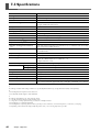
7-3 Specifications ......................................................................................................................................................... 66
CutStudio is a trademark of Roland DG Corp.
Windows® is either a registered trademark or trademark of Microsoft® Corporation in the United States and/or other countries.
Macintosh and Mac OS are registered trademarks or trademarks of Apple Computer, Inc. in the USA and other countries.
Adobe and Adobe Illustrator are either registered trademarks or trademarks of Adobe Systems Incorporated in the United States and/or other countries.
Corel and CorelDRAW are registered trademarks or trademarks of Corel Corporation or Corel Corporation Limited.
Other company names and product names are trademarks or registered trademarks of their respective holders.
Copyright© 2005-2008 Roland DG Corporation
2
http://www.rolanddg.com/
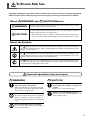
To Ensure Safe Use
Improper handling or operation of this machine may result in injury or damage to property.
Points which must be observed to prevent such injury or damage are described as follows.
About
WARNING and
WARNING
CAUTION Notices
Used for instructions intended to alert the user to the risk of death or severe
injury should the unit be used improperly.
Used for instructions intended to alert the user to the risk of injury or material
damage should the unit be used improperly.
CAUTION
* Material damage refers to damage or other adverse effects caused with respect to the home and all its furnishings, as well to domestic animals or pets.
About the Symbols
The
symbol alerts the user to important instructions or warnings. The specific meaning of
the symbol is determined by the design contained within the triangle. The symbol at left means
"danger of electrocution."
The
symbol alerts the user to items that must never be carried out (are forbidden). The
specific thing that must not be done is indicated by the design contained within the circle. The
symbol at left means the unit must never be disassembled.
The symbol alerts the user to things that must be carried out. The specific thing that must be
done is indicated by the design contained within the circle. The symbol at left means the powercord plug must be unplugged from the outlet.
Incorrect operation may cause injury
WARNING
Be sure to follow the operation procedures described in this manual.
Failure to follow the procedures may cause sudden operation or the like of the machine, which
may result in unexpected injury.
Never allow children near the machine.
The machine includes locations and components
that pose a danger to children, and major accident, including injury, blindness, or choking, may
occur.
CAUTION
Keep your hands away from the blade protector while the cutting carriage is in
motion.
Failure to do so may result in injury.
Install in a level and stable location.
Failure to do so may result in falling of the machine, leading to injury.
Do not disassemble, repair, or modify.
Doing so may lead to fire or abnormal operation resulting in injury.
3
To Ensure Safe Use
Danger of electrical short, shock, electrocution, or fire
WARNING
Do not use with any electrical power supply that does not meet the ratings displayed on the AC adapter.
Use with any other power supply may lead to
fire or electrocution.
Do not use with any power supply other
than the dedicated AC adapter.
Use with any other power supply may lead to
fire or electrocution.
Never operate the machine or insert or
remove its power plug with wet hands.
Doing so may result in electrical shock or electrocution.
Never allow the machine to get wet, or
apply gasoline, thinner, or any other flammable material to it.
Current leakage may cause electrical shock, electrocution, or combustion and fire.
Never allow hairpins, coins, matches, or
any other object to get inside the machine
through the ventilation ports.
Doing so may cause and electrical short, resulting in shock or electrocution, or the inserted
object may catch fire.
Never place gasoline, alcohol, thinner, or
any other flammable material near the
machine, or use an aerosol spray close to
the machine.
Doing so may cause fire.
Never damage the power cord or pull it
with force.
Doing so may tear the cord's insulation, causing
an electrical short and resulting in electrical
shock, electrocution, or fire.
Never place any object on the power cord,
bend the power cord using excessive force,
or allow the power cord to become deformed.
If it becomes deformed, the deformed location
may grow hot and cause fire.
4
Never use the machine with the power
cord bound into a bundle or roll.
If the cord is in a bundle or roll, it may grow hot
and cause fire.
Never use any power cord other than the
power cord included with the machine.
Also, never use a power strip or extension
cord.
The power strip or extension cord may grow
hot and cause fire.
Do not use with a damaged AC adapter,
power cord or plug, or with a loose electrical outlet.
Doing so may lead to fire, electrical shock, or
electrocution.
When unplugging the electrical power
cord from the power outlet, grasp the plug,
not the cord.
Unplugging by pulling the cord may damage it,
leading to fire, electrical shock, or electrocution.
In the event of an abnormal state (such as
smoke or sparks, odor or burning or unusual noise), immediately unplug the
power cord.
Failure to do so may result in fire, electrical
shock, or electrocution. Immediately disconnect
the power cord and contact your Roland DG
Corp. service center.
When not in use for several hours, unplug
the power-cord plug from the electrical
outlet.
Failure to do so may result in danger of electrical shock, electrocution or fire due to deterioration of electrical insulation.
To Ensure Safe Use
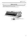
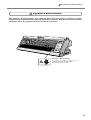
Warning Labels
Warning labels are affixed to make areas of danger immediately clear. The meanings of these
labels are as follows. Be sure to heed their warnings.
Also, never remove the labels or allow them to become obscured.
Caution: Moving Carriage
The cutting carriage moves at high speed and
pose a hazard. Keep your hands away from
the blade protector.
5
Pour utiliser en toute sécurité
La manipulation ou l'utilisation inadéquates de cet appareil peuvent causer des blessures ou
des dommages matériels. Les précautions à prendre pour prévenir les blessures ou les dommages
sont décrites ci-dessous.
Avis sur les avertissements
ATTENTION
Utilisé pour avertir l'utilisateur d'un risque de décès ou de blessure grave en
cas de mauvaise utilisation de l'appareil.
Utilisé pour avertir l'utilisateur d'un risque de blessure ou de dommage matériel
en cas de mauvaise utilisation de l'appareil.
PRUDENCE
* Par dommage matériel, il est entendu dommage ou tout autre effet
indésirable sur la maison, tous les meubles et même les animaux
domestiques.
À propos des symboles
Le symbole
attire l'attention de l'utilisateur sur les instructions importantes ou les
avertissements. Le sens précis du symbole est déterminé par le dessin à l'intérieur du triangle.
Le symbole à gauche signifie "danger d'électrocution".
Le symbole
avertit l'utilisateur de ce qu'il ne doit pas faire, ce qui est interdit. La chose
spécifique à ne pas faire est indiquée par le dessin à l'intérieur du cercle. Le symbole à gauche
signifie que l'appareil ne doit jamais être démonté.
Le symbole prévient l'utilisateur sur ce qu'il doit faire. La chose spécifique à faire est indiquée
par le dessin à l'intérieur du cercle. Le symbole à gauche signifie que le fil électrique doit être
débranché de la prise.
L'utilisation incorrecte peut causer des blessures
ATTENTION
S'assurer de suivre les procédures
d'utilisation décrites dans ce manuel.
Si les procédures indiquées ne sont pas suivies,
le fonctionnement de l'appareil peut être
déclenché soudainement, ce qui risque de causer
des blessures.
Ne jamais laisser d'enfants s'approcher de
l'appareil.
Des éléments et des surfaces de l'appareil
présentent des risques pour les enfants. Il
pourrait se produire un accident grave qui
causerait des blessures, ou créerait un risque
de cécité ou de suffocation.
6
Ne pas démonter, réparer ni modifier.
Démonter, réparer ou modifier l'appareil risque
de provoquer un incendie ou de causer un
fonctionnement anormal entraînant des
blessures.
Pour utiliser en toute sécurité
PRUDENCE
Ne pas approcher les mains de la protection de la lame lorsque le chariot de coupe
se déplace.
Il est possible de se blesser.
Installer sur une surface stable.
Sinon, l'appareil risque de se renverser et de
causer des blessures.
Risque de décharge ou de choc électrique,
d'électrocution ou d'incendie
ATTENTION
Ne pas utiliser avec une source
d'alimentation électrique non conforme
à la norme indiquée sur l'adaptateur AC.
Utiliser l'appareil avec une autre source
d'alimentation risque de provoquer un incendie
ou de causer une électrocution.
Utiliser uniquement avec l'adaptateur AC
fourni.
Utiliser l'appareil avec une autre source
d'alimentation risque de provoquer un incendie
ou de causer une électrocution.
Ne jamais utiliser l’appareil, insérer la
prise dans le réceptacle ou l’en enlever si
on a les mains mouillées.
Il y a risque de décharge électrique ou
d'électrocution.
Ne jamais permettre que l'appareil soit
mouillé; ne jamais y appliquer d'essence,
de diluant ni aucun matériau inflammable.
Une fuite de courant peut causer un choc
électrique, l'électrocution ou la combustion et
un incendie.
Ne jamais laisser des épingles à cheveux,
des pièces de monnaie, des allumettes ni
aucun autre objet pénétrer dans l'appareil
par les orifices de ventilation.
Cela crée un risque de décharge électrique ou
d'électrocution. En outre, les objets peuvent
prendre feu.
Ne jamais placer de l'essence, du diluant
ni aucun matériau inflammable près de
l'appareil; ne jamais utiliser de produits en
aérosol près de l'appareil.
Cela crée un risque d'incendie.
Ne jamais endommager le câble
d'alimentation ni le tirer vigoureusement.
Cela risque de déchirer l'isolant du câble et de
causer un court-circuit, ce qui aurait comme
résultat un choc électrique, l'électrocution ou
un incendie.
Ne jamais placer d'objets sur le cordon
d'alimentation,
plier
le
câble
d'alimentation en utilisant une force excessive ni laisser le câble d'alimentation
se déformer.
Si le câble se déforme, la section affectée peut
surchauffer et causer un incendie.
Ne jamais utiliser l'appareil si le câble
d'alimentation est attaché ou enroulé.
S'il est attaché ou enroulé, il peut surchauffer et
causer un incendie.
Ne jamais utiliser un cordon
d'alimentation autre que celui qui est
fourni avec l'appareil. Ne jamais non plus
utiliser de bande d'alimentation électrique
ni de rallonge.
La bande d'alimentation ou la rallonge peuvent
surchauffer et causer un incendie.
7
Pour utiliser en toute sécurité
ATTENTION
Ne pas utiliser avec un adaptateur, un fil
ou une fiche endommagés; ne pas
brancher dans une prise mal fixée.
Négliger de suivre cette consigne risque de
provoquer un incendie ou de causer une
décharge électrique ou une électrocution.
Pour débrancher l'appareil, saisir la fiche
et non le fil électrique.
Tirer sur le fil peut l'endommager, ce qui risque
de provoquer un incendie ou de causer une
décharge électrique ou une électrocution.
Ne pas utiliser l'appareil s'il est dans un
état anormal (p.ex., émission de fumée,
odeur de brûlé, bruit inhabituel ou autre
anomalie).
Ne pas respecter cette consigne risque de
provoquer un incendie ou une électrocution.
Débrancher immédiatement la fiche de la prise
et communiquer avec le revendeur ou le centre
de service autorisés de la société Roland DG.
Si l'appareil reste inutilisé pendant
plusieurs heures, débrancher la fiche de
la prise électrique.
Négliger de suivre cette consigne peut créer un
risque de décharge électrique ou d'électrocution
ou provoquer un incendie à cause de la
détérioration de l'isolant électrique.
8
Pour utiliser en toute sécurité
Vignettes d'avertissement
Des vignettes d'avertissement sont apposées pour qu'il soit facile de repérer les zones
dangereuses. La signification des vignettes est donnée ci-dessous. Respecter les avertissements.
Ne jamais retirer les vignettes et ne pas les laisser s'encrasser.
Attention : Chariot mobile
Le chariot de coupe se déplace très
rapidement et peut être dangereux.
Ne pas approcher les mains.
9
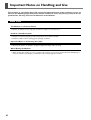
Important Notes on Handling and Use
This machine is a precision device. To ensure the full performance of this machine, be sure to
observe the following important points. Failure to observe these may not only result in loss of
performance, but may also cause malfunction or breakdown.
Main Unit
This Machine Is a Precision Device
➢Handle carefully, and never subject the machine to impact or excessive force.
Install in a Suitable Location
➢Install in a location having the specified temperature and relative humidity.
➢Install in a stable location offering good operating conditions.
Important Notes on Connecting the Cables
➢Connect the power cord and the computer's input and output cables securely.
When Moving the Machine
➢When moving the machine, be sure to support the machine at its bottom, using both hands. Attempting to
move the machine by holding it at a different location may damage the machine.
10
About the Documentation
Included Documentation
The following documentation is included with the machine.
Printed Document
GX-24 User's Manual (This document)
This describes how to install and set up the machine, basic cutting operations, and other such matters.
Online Help (Manuals in Electronic Format)
These describe how to use the programs, drivers, and other software. Each is installed automatically whenever you
install and set up the corresponding program or driver.
➢ Roland CutStudio Online Help (Windows)
This describes in detail the operation and features of Roland CutStudio, the included Windows-based cutting program.
➢ CAMM-1 Driver Online Help (Windows)
This describes in detail the operation and features of the driver.
➢ CutStudio Plug-in for Adobe Illustrator Online Help (Windows/Macintosh)
This describes in detail the operation and features of the software plug-in. The content of the version for the Macintosh
is slightly different.
Operation Manuals (Manuals in Electronic Format)
The following operation manuals are included. To view them, first install them on your computer.
For information on how to install the operation manuals, refer to the following page.
☞ p 29 "Installing the Operation Manuals" (Windows)
☞ p 33 "If You're Using a Macintosh" (Macintosh)
The manuals you view differ depending on whether you're using Windows or a Macintosh.
Operation Manuals for Windows
➢ GX-24 Reference Guide
This describes the features and details of the machine, lists the menu items, and provides detailed information about
matters not covered in this document, such as what to do to resolve any problems that may occur.
➢ CutStudio Plug-in for Adobe Illustrator/CorelDRAW Setup Guide
This describes how to set up the CutStudio plug-in.
➢ Printing and Cutting Guide (Guide to cutting using crop marks -- Windows version)
This describes how to print an image on a printer and cut contour lines on this machine using the crop-mark feature
that lets you align an image and contours.
Operation Manuals for Macintosh
➢ GX-24 Reference Guide
This describes the features and details of the machine, lists the menu items, and provides detailed information about
matters not covered in this document, such as what to do to resolve any problems that may occur.
➢ Macintosh Cutting Guide
This describes such matters as how to carry out cutting using this machine with a Macintosh.
For detailed information about the include programs and other software, refer to the following page.
☞ p 26 "Included Software"
11
About the Documentation
Viewing the Manuals in Electronic Format
If you encounter a problem, then along with this document, also take a look at the manuals in electronic format. Read
on to learn how to view the electronic-format manuals.
Windows
➢ Roland CutStudio Online Help (Windows)
After you start CutStudio, go to the menu bar and click [Help], then [Contents].
Alternatively, click [Start], point to [Programs] (or [All Programs]), then point to [Roland CutStudio].
Click [CutStudio Help].
➢ CAMM-1 Driver Online Help (Windows)
Go to the driver's window and click the [Help] button.
➢ CutStudio Plug-in for Adobe Illustrator Online Help
At the [Roland CutStudio] palette, click the
button, then click [Help].
For more information, refer to the "CutStudio Plug-in for Adobe Illustrator/CorelDRAW Setup Guide."
➢ Operation Manuals
Click [Start], point to [Programs] (or [All Programs]), then point to [Roland GX-24 Operation Manuals].
Click the electronic-format manual you want to view.
Macintosh
➢ CutStudio Plug-in for Adobe Illustrator Online Help
At the [Roland CutStudio] palette, click the
button, then click [Help].
For more information, refer to the "Macintosh Cutting Guide."
➢ Operation Manuals
On the desktop, double-click the icon for the manual.
12
Chapter 1:
Getting Started
13
1-1 Machine Features
This is a USB/Serial compatible high-performance cutting machine that offers features like those described below.
Quiet
➢Quiet cutting achieved through use of servo motors
Easier to Use
➢Two-line backlit display for clear visibility even in dark locations
➢Operation panel and menus organized with a simple, easy-to-understand layout
➢Comes with Roland CutStudio which is a Windows-based cutting program enabling high-quality cutting with
easy operation
Versatile Range of Practical Applications
➢Included software plug-ins that enable CutStudio to cut data created using commercially available programs
➢Crop-mark feature that can align an image and contour lines when printing an image on a printer and cutting
the contours on this machine
14
Chapter 1: Getting Started
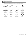
1-2 Included Items
The following items are packed together with the unit. Make sure they are all present and accounted for.
AC adapter: 1
Power cord: 1
Blade: 1
Blade holder: 1
Pin: 1
Roller base: 1
Separating knife: 1
Tweezers: 1
Test-use material: 1
(Colored material)
Apprication tape: 1
(Transparent tape)
CD-ROM: 1
User's Manual
(This document): 1
USB cable: 1
Chapter 1: Getting Started
15
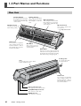
1-3 Part Names and Functions
Main Unit
Left Pinch Roller
Cutting Carriage
This clamps the material when
the loading lever is raised. You
set this at the left-hand edge
of the material.
This is where you install the
blade holder. It moves to the
left and right to cut the material.
Blade Protector
Right Pinch Roller
This clamps the material when
the loading lever is raised. You
set this at the right-hand edge
of the material.
Operation Panel
This protects the tip of the
blade during cutting.
You use this to perform various operations.
☞ p 17 "Operation Panel"
Guide Lines
You use these for alignment
when loading material. You
load the material so that its
left and right edges are parallel to the raised lines.
Grit Rollers
These rollers feed out
material toward the front
of the machine.
Knife Guide
This lets you cut off a piece of material
without first removing the material from
the machine, by inserting the separating
knife and moving it along the guide.
Loading Lever
Tray
You can place items such as blade
holders and blades here.
You operate this when
you load material.
Guide Lines
You use these for alignment
when loading material. You
load the material so that its
left and right edges are parallel to the raised lines.
Power-cord Connector
This supplies power to the machine.
Serial(RS-232C) Connector
This connects a serial cable.
USB Connector
This connects a USB cable.
16
Chapter 1: Getting Started
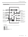
1-3 Part Names and Functions
Operation Panel
Display
This displays various setting
menus and other information.
PAUSE Key
This interrupts the operation
in progress. Pressing it a second time resumes the operation.
TEST Key
Pressing and holding this for
one second or longer cuts a
pre-registered test pattern.
ORIGIN Key
Pressing and holding this for
one second or longer sets the
origin point at the present
location of the blade.
MENU Key
Pressing this repeatedly
switches sequentially among
the presently set cutting conditions, the menu mode, and
the width-display screen.
Cursor Keys
You use these to perform such
operations as moving the cutting carriage or material, and
selecting and setting various
menu items.
FORCE Key
This displays the menu for
adjusting the blade force.
ENTER Key
PEN FORCE Slider
POWER Button
This lets you fine-tune the
blade force. You can even
perform adjustment while
cutting is in progress.
Pressing this switches on the
power, making the button
light up blue. To switch off the
power, you hold it down for
one second or longer.
This is used to choose menu
items and confirm settings.
Panel Notation
In this document, the keys on the control panel are indicated by the following images.
MENU Key
FORCE Key
ENTER Key
TEST Key
ORIGIN Key
Cursor Keys
PAUSE Key
Chapter 1: Getting Started
17
18
Chapter 2:
Preparing the GX
This describes how to set up and prepare the machine, including how to
install it and make the cable connections.
19
2-1 Installing
Deciding On an Installation Site
Install in a stable location offering good operating conditions. An unsuitable location can cause accident, faulty
operation, or breakdown.
WARNING
Install in a level and stable location.
Otherwise the machine may tip over and cause injury.
Unsuitable Installation Sites
➢Locations subject to shaking or vibration
➢Locations where the floor is tilted, not level, or unstable
➢Locations exposed to direct sunlight or near air-conditioning or heating equipment
➢Locations within 1 m (39-3/8 in.) of strong illumination
➢Dusty locations
➢Locations exposed to considerable electrical or magnetic noise, or other forms of electromagnetic energy
➢Locations with poor heat radiation
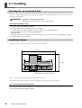
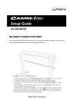
Installation Space
The space shown in the figure is required in order to use this machine.
950 mm
500 mm
Height: 300 mm
(When using a special stand: 1000 mm)
Place in a location that has no wall or other obstruction to the rear.
The material moves during cutting. Never place any object at the front or rear of the machine.
Use a special stand (sold separately)
The special stand (part number PNS-24) is sold separately. For more information, contact your vendor or the
nearest authorized Roland DG Corp dealer.
20
Chapter 2: Preparing the GX
2-1 Installing
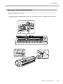
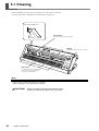
Removing the Packing Materials
Tape and packing materials are attached to the machine to protect it from vibration during transportation. When
installation is complete, remove these.
➢Remove all packing materials. Any that remain may cause faulty operation or breakdown when the power is
switched on.
Chapter 2: Preparing the GX
21
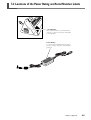
2-2 Connecting the Cables
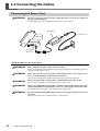
Connecting the Power Cord
WARNING
Do not use with any electrical power supply that does not meet the ratings displayed on the AC adapter.
Use with any other power supply may lead to fire or electrocution.
AC Adapter
Power cord
Power-cord
Connector
Important Notes on the Power Cord
WARNING
Never damage the power cord or pull it with force.
Doing so may tear the cord's insulation, causing an electrical short and resulting in electrical shock, electrocution, or fire.
WARNING
Never place any object on the power cord, bend the power cord using excessive
force, or allow the power cord to become deformed.
If it becomes deformed, the deformed location may grow hot and cause fire.
WARNING
Never use the machine with the power cord bound into a bundle or roll.
If the cord is in a bundle or roll, it may grow hot and cause fire.
WARNING
Never use any AC adapter and power cord other than the AC adapter and power
cord included with the machine. Also, never use a power strip or extension cord.
The power strip or extension cord may grow hot and cause fire.
WARNING
Do not use with a damaged AC adapter, power cord or plug, or with a loose electrical outlet.
Doing so may lead to fire, electrical shock, or electrocution.
22
Chapter 2: Preparing the GX
2-2 Connecting the Cables
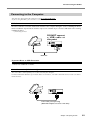
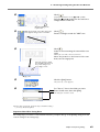
Connecting to the Computer
You make the connection to the computer using the included USB cable.
(If you're using Windows, you can also use a serial cable.)
USB Connection
Be sure to make the connection between the machine to the computer during the course of installing the driver.
Driver installation may fail and the machine may become unusable If you connect a USB cable before starting
installing the driver.
☞ p 28 "Installing the Driver"
DO NOT connect
a USB cable at
this point.
USB cable
Important Notes on USB Connection
➢Never use a USB hub or the like.
Serial Connection(Windows only)
The serial cable is sold separately. Use a cable suited to your computer.
For more information about the specifications of the serial interface, refer to the "GX-24 Reference Guide" (electronicformat manual).
Serial cable (sold separately)
(RS-232C-compliant crossover serial cable)
Chapter 2: Preparing the GX
23
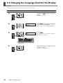
2-3 Changing the Language Used for the Display
Change the language used for the display to match your preference.
Procedure
➊
Hold down
button.
and press the power
The power comes on.
Operation
Panel
➋
LANG._ENGLISH
*_ENGLISH
Press
to choose the language you
want to use for the display.
In this example, we'll choose [ENGLISH].
➌
SELECT SHEET
*ROLL
Press
.
The cutting carriage moves to the right edge.
Be careful not to touch it.
Cutting carriage
➍
Hold down the power button for one
second or longer.
The power is switched off.
24
Chapter 2: Preparing the GX
Chapter 3:
Installing/Uninstalling
Software
This describes how to install, set up and uninstall the included programs
and other software.
25
3-1 About the Included Software
Included Software
The included CD-ROM contains the following software.
Software for Windows
■ Windows Driver
This is a Windows-based driver required for sending data from a computer to the machine. Be sure to install it
■ Roland CutStudio
This is a Windows-based cutting program that enables you to accomplish high-quality cutting through easy operation.
■ CutStudio Plug-in for Adobe Illustrator
This is a software plug-in that lets you send data created using Adobe Illustrator directly to CutStudio.
■ CutStudio Plug-in for CorelDRAW
This is a software plug-in that lets you send data created using Corel CorelDRAW directly to CutStudio.
Software for Macintosh
■ CutStudio Plug-in for Adobe Illustrator
This is a software plug-in that lets you create and cut cutting data using Adobe Illustrator.
26
Chapter 3: Installing/Uninstalling Software
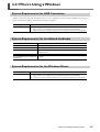
3-2 If You're Using a Windows
System Requirements for USB Connection
Making a USB connection with Windows requires use of a computer that meets all of the following system requirements. Please note that other configurations cannot be supported.
Operating system
Computer
Windows 98 SE (Second Edition)/Me/2000/XP
1) Computers preinstalled with Windows 98 SE/Me/2000/XP at the time of purchase
(This includes such computers later upgraded to Windows Me/2000/XP.)
2) Computers on which USB operation is assured by the manufacturer of computers
System Requirements for the Roland CutStudio
Operating system
Computer
Drive
Monitor
Windows 98 SE (Second Edition)/Me/2000/XP
Memory (RAM)
Free hard-disk space required for
installation
128 MB or more recommended
Computer running Windows
CD-ROM drive
Windows-compatible monitor capable of displaying of 16 bit color (High
Color) or more
10 MB
System Requirements for the Windows Driver
Operating system
Computer
Windows 98 SE (Second Edition)/Me/2000/XP
1) Computers preinstalled with Windows 98 SE/Me/2000/XP at the time of purchase
(This includes such computers later upgraded to Windows Me/2000/XP.)
2) Computers on which USB operation is assured by the manufacturer of computers
Chapter 3: Installing/Uninstalling Software
27
3-2 If You're Using a Windows
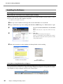
Installing the Software
Installing the Driver
Never make the connection to the computer before installing.
Keep the machine and the computer unconnected until you carry out this installation operation. Failure to follow
the correct procedure may make installation impossible.
☞ p 30 "What to Do If Installation Is Impossible"
➊ Before you start installation and setup, make sure the USB cable is not connected.
➋ Log on to Windows. If you are installing under Windows 2000/XP, log on as "Administrators” right.
➌
Insert the included CD-ROM into the CD-ROM
drive.
After a short wait, the setup menu shown at left appears.
➍
Click this.
The Installation and Setup Guide appears.
If you're using Windows 98 SE, Windows Me, or Windows 2000, the Installation and Setup Guide and the
Setup program appear.
➎ Follow the instructions in the Installation and Setup Guide to finish installing.
Installation and Setup Guide
Setup program
(Windows 98 SE/Me/2000)
If the [Driver Setup] Window Doesn't Appear
If you're using Windows 98 SE,Windows Me, or Windows 2000 and the Setup program doesn't appear, first check
the taskbar at the bottom of the screen. If [Driver Setup] is displayed, the program is running. Go to the taskbar
and click [Driver Setup] to display the window for the Setup program.
Taskbar
28
Chapter 3: Installing/Uninstalling Software
Click this.
3-2 If You're Using a Windows
Installing CutStudio
Install the Windows-based cutting program "CutStudio."
➊
Display the setup menu of the Roland GX-24 Software Package.
➋
Click [Install].
The setup window appears.
➌ Thereafter, follow the instructions in the messages to complete installation and setup.
Next, you install the operation manuals.
Installing the Operation Manuals
➊
Display the setup menu of the Roland GX-24 Software Package.
➋
Click [Install].
The setup window appears.
➌ Thereafter, follow the instructions in the messages to complete installation and setup.
➍ At the setup menu, go to the upper right and click the [X] to close the window.
This completes the installation and setup for the software.
Installing CutStudio Plug-in
For information about how to install and set up the CutStudio Plug-in, refer to the "CutStudio Plug-in for Adobe
Illustrator/CorelDRAW Setup Guide" (electronic-format manual).
Chapter 3: Installing/Uninstalling Software
29
3-2 If You're Using a Windows
What to Do If Installation Is Impossible (USB connection)
If installation quits partway through, or if the wizard does not appear when you make the connection with a USB
cable, take action as follows.
Windows 2000/XP
➊ If the [Found New Hardware Wizard] appears, click [Finish] to close it.
➋ Display [System Properties].
Windows XP
Click the [Start] menu, then right-click [My Computer]. Click [Properties].
Windows 2000
Right-click [My Computer] on the desktop. Click [Properties].
➌
Click the [Hardware] tab, then click [Device Manager].
The [Device Manager] appears.
➍ Delete [GX-24] (or [Unknown device]).
At the [View] menu, click
[Show hidden devices].
Go to the [Action] menu, and
click [Uninstall].
Find [Printers] or [Other
device], then double-click it.
Click [GX-24] (or [Unknown
device]).
After the screen shown at left
appears, click [OK].
30
Chapter 3: Installing/Uninstalling Software
3-2 If You're Using a Windows
➎ Close the [Device Manager] and click [OK].
➏ Detach the USB cable connected to the computer.
➐ Restart Windows, then uninstall the driver.
☞ p 32 "Uninstalling the Driver"
➑ Redo the installation from the beginning.
☞ p 28 "Installing the Driver"
Windows 98 SE/Me
➊ Refer to "Uninstalling the Driver" on the following page and uninstall the driver.
☞ p 32 "Uninstalling the Driver"
➋ Redo the installation from the beginning.
☞ p 28 "Installing the Driver"
Chapter 3: Installing/Uninstalling Software
31
3-2 If You're Using a Windows
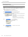
Uninstalling the Driver
When uninstalling the driver, perform following operation.
Procedure
➊ Before you start uninstallation of the driver, unplug the USB cables from your computer.
➋ Log on to Windows. If you are installing under Windows 2000/XP, log on as “Administrators” right.
➌ Insert the included CD-ROM into the CD-ROM drive.
The setup menu appears.
Go to the upper right and click the [X] to close the setup menu.
➍
From the [Start] menu, click [Run].
The screen shown at left appears.
➎
For [Open], type in the information shown below, then click
[OK].
In this illustration, drive D is specified
as the CD-ROM drive.
Windows 2000/XP
(CD-ROM drive letter ):\Drivers\WIN2KXP\SETUP.EXE
Windows 98 SE/Me
(CD-ROM drive letter):\Drivers\WIN9X\SETUP.EXE
The Setup program starts and the [Driver Setup] window appears.
32
➏
Choose [Uninstall].
Choose [Roland GX-24].
Click [Start].
➐
Click [Yes] to restart the computer.
Chapter 3: Installing/Uninstalling Software
3-3 If You're Using a Macintosh
The included CD-ROM contains the "Mac OS Installation and Setup Guide," which explains how to install and set up
the software and operation manuals for the Macintosh. If you're using a Macintosh, follow the steps below to display
the file, then follow the explanation to perform installation and setup.
Procedure
➊ Insert the included CD-ROM into the CD-ROM drive.
➋ Double-click the [Roland GX-24] icon that appears on the desktop.
➌ Double-click the "Install_e.html" icon.
The [Mac OS Installation and Setup Guide] appears.
➍ Thereafter, follow the instructions in the [Mac OS Installation and Setup Guide] to install and set up
the software and operation manuals.
Chapter 3: Installing/Uninstalling Software
33
34
Chapter 4:
Performing Cutting
This describes basic cutting operations under Windows, using the included
test-use material in the examples of cutting operations. It also describes
the main operations when using other materials. For other operations not
covered in this chapter, refer to the "GX-24 Reference Guide" (electronicformat manual).
If you're using a Macintosh, refer to the "Macintosh Cutting Guide" (electronic-format manual).
35
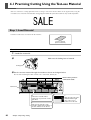
4-1 Practicing Cutting Using the Test-use Material
Now let's learn basic cutting operations while creating a sticker like the one shown in the figure below, using the
included test-use material and CutStudio cutting program. Follow the procedure below to carry out the operations.
Step 1: Load Material
Load the included test-use material on the machine.
Test-use material
(Colored material)
Procedure
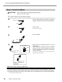
1. Load the material.
➊
Make sure the loading lever is lowered.
Loading lever
➋ Pass the test-use material through the machine as shown in the figure below.
Pass the material through so that its short side is at the front, toward you.
Pinch-roller positionverification marks
Guide lines
Å
Pull out the material until its
leading edge is positioned over the
guide lines.
É
Make sure the left edge of the
material is within the boundaries of
the wide indicator at the far left.
36
Chapter 4: Performing Cutting
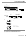
Ç
Align the right edge of the
material with the right
edge of the second
indicator from the left.
4-1 Practicing Cutting Using the Test-use Material
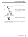
➌ Move the pinch rollers so that they are positioned at the edges of the material and also inside the
areas of the pinch-roller position-verification marks.
Be sure to position the left
pinch roller inside the area
of the wide mark.
Pinch-roller positionPinch roller verification mark
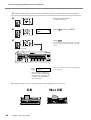
Be careful to position the pinch rollers so that they are not too close to the edges of the material and do not
extend beyond the edges of the material.
OK
Not OK
Pinch-roller positionverification mark
Pinch roller
Do not extend beyond
the mark.
➍
Guide line
Align the left edge of the material so that it lies parallel to
the guide lines.
Guide line
➎
Raise the loading lever.
The material is secured in place.
Important Notes
➢Do not use excessive force when moving the loading lever. Doing so may damage it.
➢If the condition of the material is as described below, then stretch or flatten it before use.
•The material is curled upward.
•The leading edge of the material is bent or creased.
Chapter 4: Performing Cutting
37
4-1 Practicing Cutting Using the Test-use Material
2. Switch on the power to the machine and make it ready to receive data from the computer.
➊
Press the power button.
The power comes on.
➋
Press
SELECT SHEET
* PIECE
➌
Press
to choose "PIECE."
.
The cutting carriage moves to the left edge
and the material moves forward and backward.
Cutting carriage
Width
Length
Then, the cuttable width and length appear
on the display.
W : 175mm
L : 233mm
* These values are examples for
reference only. The actual width
and length vary according to the
positions of the pinch rollers
and other factors.
After operation stops, be sure to check and make sure the material has not come loose.
OK
38
Chapter 4: Performing Cutting
Not OK
4-1 Practicing Cutting Using the Test-use Material
➍
Cutting speed Cutting direction
20 cm/s
50 gf 0.250 mm
A
Cutting force Blade offset
Make sure that material feed was performed correctly, then press
.
Make sure the values for the items are displayed as shown in the figure. For detailed
information about the values displayed, refer
to the "GX-24 Reference Guide" (electronicformat manual).
This completes the procedure for loading the material. Go on to "Step 2: Install the Blade."
☞ p 40 "Step 2: Install the Blade"
If the material comes loose
If the material comes loose from the pinch rollers, take action as described below, then redo the procedure from
the beginning of Step 1.
☞ p 36 "Step 1: Load Material"
➊ Hold down the power button for one second or longer.
The power is switched off. If this does not switch off the power, then disconnect the AC adapter from the machine.
➋ Lower the loading lever and remove the material.
If You're Using Lengthy Flat Material
Material such as the test-use material that is pre-cut to a certain length is called "flat material." When you're using
ordinary flat material, choosing [PIECE] displays the width and length. However, if the length exceeds 1.6 meters,
the length is not displayed when [PIECE] is chosen. If you're using flat material whose length is more than 1.6
meters, choose [ROLL], then make sure the material does not come loose.
For more information, refer to the page indicated below.
☞ p 53 "Using Roll Material or Lengthy Flat Material"
Chapter 4: Performing Cutting
39
4-1 Practicing Cutting Using the Test-use Material
Step 2: Install the Blade
CAUTION
Do not touch the tip of the blade with your fingers.
Doing so may result in injury.
1. Insert a blade into the blade holder.
➊
Turn the blade-holder cap to tighten completely
(tighten until the cap cannot be turned further).
Blade holder
Cap
➋
Insert the pin.
Pin
Leave the pin inserted.
➌
Insert the blade.
Cap
Blade
Tip
➍
0.1 mm
Scale
Loosen
Amount of blade
extension
Adjust the amount of blade extension to match
the material.
In this example, to adjust the amount of blade
extension to the test-use material, turn the cap
counterclockwise until the blade is extended by
about 1 millimeter.
A change in extension of 0.5 mm can be made by rotating the cap one full turn.
About 1 mm
When installation is
complete
When You're Using a Variety of Materials
Depending on the type of material (such as when you're using material that has thin backing paper), it may become
necessary to adjust the amount of blade extension. Also, when stable cutting results aren't obtained, changing the
amount of blade extension may produce better results. For more information, refer to the page indicated below.
☞ p 56 "Adjusting the Cutting-in Amount"
40
Chapter 4: Performing Cutting
4-1 Practicing Cutting Using the Test-use Material
2. Install the blade holder.
➊
Loosen the screw of the cutting carriage.
Cutting carriage
➋
Support the screw from below and insert the
blade holder.
If installed without supporting the screw in this way,
cutting quality may become poor.
Insert until the collar is
flush with the surface.
➌
Screw
Support it from below.
Tighten the screw.
Tug the blade holder upward to make sure it does not
come loose.
This completes the procedure for installing the blade. Go on to "Step 3: Optimizing the Cutting Quality for the Material."
☞ p 42 "Step 3: Optimizing the Cutting Quality for the Material"
Chapter 4: Performing Cutting
41
4-1 Practicing Cutting Using the Test-use Material
Step 3: Optimizing the Cutting Quality for the Material
To obtain high-quality cutting results, then before you perform the actual cutting, carry out a cutting test to check the
cutting quality for the material.
Performing a Cutting Test
➊
Make sure the [PEN FORCE] slider is centered
(at "0" on the scale).
➋
Hold down
for one second or longer.
The test pattern is cut.
➌
Press
to feed the material toward the
front, then use the included tweezers to peel off
the cut shapes and check the cutting quality.
Tweezers
➍
Circle 1
Peel off circle 1.
Circle 1 peels off alone.
Proceed to ➎.
Rectangle 2 also peels off.
Refer to "Changing the Blade Force" on the
following page and increase the blade force.
Rectangle 2
➎ Peel off rectangle 2.
The blade leaves faint traces on the material's backing paper.
The blade force is correct. Go on to "Step 4: Set the Origin Point."
☞ p 45 "Step 4: Set the Origin Point"
The blade trace is indistinct.
Refer to "Changing the Blade Force" on the following page and increase the blade force.
The blade trace is too deep and cuts into the backing paper.
Refer to "Changing the Blade Force" on the following page and reduce the blade force.
42
Chapter 4: Performing Cutting
4-1 Practicing Cutting Using the Test-use Material
If the two shapes peel off together or show other problems with cutting, adjust the blade force and perform a cutting
test a second time. First, change the blade force.
Changing the Blade Force
➊
Make sure the [PEN FORCE] slider is centered
(at "0" on the scale).
➋
2
FORCE 50 gf
Press
Press
.
.
FORCE 50 gf
*60 gf
USE
to make the setting
for the value.
Press
to enable the setting.
1
➌
1
2
➍
FORCE 60 gf
20 cm/s
60 gf 0.250 mm
A
Press
or
to go back to the
screen shown at left.
After you have changed the blade force, to avoid wasting material, move the cutting carriage to the location right next
to where you just performed the cutting test.
To move the cutting carriage, use the cursor keys.
Continued on the next page
Chapter 4: Performing Cutting
43
4-1 Practicing Cutting Using the Test-use Material
Moving the Cutting Carriage
Pressing
moves the cutting carriage, and pressing
moves the material.
When you want to adjust the position a little at a time, press the
key repeatedly, holding it down for only a short time with each
press.
To move continuously for a long distance, hold down the key.
When you press and hold down the key, movement proceeds slowly
for the first 20 millimeters of movement distance.
When the movement distances exceeds 20 millimeters, movement
speeds up.
➊
Move slowly Move rapidly
Hold down
until the material reaches the location
where its movement stops.
The material moves toward the rear.
➋
Use
to move the cutting carriage to the location
where the cutting test can be performed.
Position at a location away from where you peeled off the material
earlier.
Now you're ready to perform a cutting test again. Carry out the cutting test and check the cutting quality for the
material.
☞ p 42 "Performing a Cutting Test"
Repeat the procedure described above until the test results are acceptable.
When you obtain acceptable results, go on to "Step 4: Set the Origin Point."
☞ p 45 "Step 4: Set the Origin Point"
44
Chapter 4: Performing Cutting
4-1 Practicing Cutting Using the Test-use Material
Step 4: Set the Origin Point
Set the origin point for determining the cutting position. If you have performed a cutting test, then move the cutting
carriage to a location where it does not overlap with the test area. Doing this lets you use the material with minimal
waste.
Procedure
➊
Use
to move the cutting carriage to the left edge.
Use
to move the material to the rear, positioning
the traces from the cutting test toward the front of the
blade protector.
Blade protector
The blade moves over this line.
Setting the origin point makes the
area behind this line the cutting
range.
➋
Hold down
longer.
ORIGIN SET
First, Screen 1 flashes, then when the settings
are completed Screen 2 appears.
Screen 1
20 cm/s
50 gf 0.250 mm
for one second or
A
Screen 2
This completes all the preparations for cutting. Go on to "Step 5: Create Cutting Data."
☞ p 46 "Step 5: Create Cutting Data"
Chapter 4: Performing Cutting
45
4-1 Practicing Cutting Using the Test-use Material
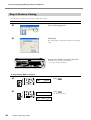
Step 5: Create Cutting Data
Use the Windows-based cutting program "CutStudio" to create cutting data.
Important Note
If you are using Windows 2000/XP, log on to Windows as "Administrators” right.
1. Start CutStudio.
Click [Start], then point to [All Programs] (or
[Program]).
Point to [Roland CutStudio], then click
[CutStudio].
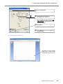
2. Make the settings for the cutting range.
46
Chapter 4: Performing Cutting
➊
Click [File], then click [Cutting Setup].
➋
For [Name], choose "Roland GX-24."
➌
Click [Properties].
The [Cutting setup] screen appears.
The [Roland GX-24 Printing Preferences] screen
appears.
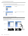
4-1 Practicing Cutting Using the Test-use Material
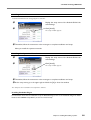
➍
Click the [Size] tab.
➎
(*)Click [Get from Machine].
The cuttable range is displayed.
* If you're using a serial connection, enter manually the values of the width
(W) and length (L) displayed on the
machine's display.
➏
Click [OK].
➐
Click [OK] again to close the [Cutting
setup] window.
The cutting range has now been set.
The white area is the cutting
range. Text or shapes drawn
outside this range are not cut.
Chapter 4: Performing Cutting
47
4-1 Practicing Cutting Using the Test-use Material
3. Insert text and shapes to create the cutting data.
In this example, we'll enter the word "SALE" as the text and draw a frame around it to make it easier to peel off later.
➊
Click [
➋
Click anywhere in the white area, then type in
"SALE."
].
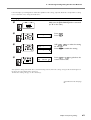
Arrange the text and shapes at the bottom of the window.
When you lay out text and shapes using CutStudio, it is a good idea to arrange them at the bottom of the window.
This can prevent wasteful feed of material.
In the CutStudio window, the leading edge of the loaded material corresponds to the bottom edge of the cutting
range. This means that when you lay out text at the bottom of the CutStudio window, the text is cut close to the
leading edge of the material.
CutStudio screen
Actual cutting
position
48
Chapter 4: Performing Cutting
The material is fed
over a distance
equal to this length,
then cutting starts.
4-1 Practicing Cutting Using the Test-use Material
➌
Click [
].
Displayed around the text are ■ and ▼ symbols.
Drag the ■ and ▼ symbols for the text box to
change the size of the text.
Click, then drag to the
required size.
➍
Click the upper-left corner, then drag to the
lower right to change to the needed size.
➎
Click [
].
Draw a rectangle around the "SALE" text.
Click [
].
Select an area containing the text and the rectangle.
When you select this, the line turns blue.
Move the position to the bottom of the window, near the origin point.
Move the pointer to inside
the text. When the shape of
the pointer changes to a
cross, drag to move.
Origin point
➏
Click the [Save] button.
The [Save As] screen appears.
➐
For "Save in," choose the folder you want.
Enter the file name, then click [Save].
The data you created is saved.
After the data is prepared, go on to "Step 6: Perform Cutting."
☞ p 46 "Step 5: Create Cutting Data"
Important Note When Saving Data
The cutting range you set here is not saved. The next time you import data, go to the [Cutting Setup] menu and
redo the setting for the cutting range.
Chapter 4: Performing Cutting
49
4-1 Practicing Cutting Using the Test-use Material
Step 6: Perform Cutting
After the data is prepared, you're finally ready to start cutting.
Procedure
➊
Click the [Cutting] button.
➋
Click [OK].
The cutting data is sent from the computer and cutting
starts.
Cutting of the "SALE" text and the box ends.
Go on to "Step 7: Remove the Material."
☞ p 51 "Step 7: Remove the Material"
To Stop Cutting While in Progress
➊
➋
CONTINUE
STOP
PAUSE
ENTER
CANCEL...
20 cm/s
50 gf 0.250 mm
50
Chapter 4: Performing Cutting
Press
.
Press
.
The data is canceled.
A
4-1 Practicing Cutting Using the Test-use Material
Step 7: Remove the Material
When cutting has ended, remove the material.
Procedure
➊
➋
UNSETUP
Press
several times to display the
screen shown in the figure.
SELECT SHEET
*ROLL
Press
.
The cutting carriage returns to the standby
position.
➌
Lower the loading lever.
Remove the material.
➍
Hold down the power button for one
second or longer.
The power is switched off.
When You Want to Cut Off Only the Portion That Has Been Cut
Draw the included knife along the knife guide to cut off the material.
Knife guide
CAUTION
Do not touch the tip of the blade with your fingers.
Doing so may result in injury.
Chapter 4: Performing Cutting
51
4-1 Practicing Cutting Using the Test-use Material
Step 8: Apply the Cut Material
To apply the material you have cut, you use the included application tape. Cut it to the required size for use. Before
applying, thoroughly clean the surface where you want to affix the material to remove any dust or grease.
Procedure
➊
➋
Use tweezers to peel off any excess material,
leaving only the text.
Application tape
Cut the application tape to the required size.
Cover the cut material flush with the application tape to prevent any air from getting underneath, then transfer the material.
You can transfer the material easily by using a commercially available squeegee or the flat part of a ruler
or the like to rub the cut material from above the application tape.
➌
Affix the material together with the joined application tape to the target object, then press
down on it from above.
➍
Make sure the material is affixed to the object,
then slowly peel off the application tape.
If air becomes trapped between the material and the
application surface, forming an air bubble, then use a
needle to pop the bubble and press out the air to form
a complete seal.
➎
Applying the cut material ends.
Material After Cutting
Transfer the cut material to the application tape and affix it to the object as soon as possible. Any dust that builds
up on the surface of the material can make it difficult for the application tape to stick.
52
Chapter 4: Performing Cutting
4-2 Using a Variety of Materials
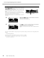
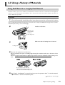
Using Roll Material or Lengthy Flat Material
With this machine, you can use not only such standard-size material as the test-use material, but also lengthy flat
material, as well as roll material (sold separately). To use flat material or roll material whose length is more than 1.6
meters, follow the steps below.
Procedure
1. (For roll material) Install the roller base, then secure the roll material in place.
If you're using flat material that is longer than 1.6 meters, refer to "Step 1: Load Material" on page 36 to secure the
material in place, then go on to the next page.
➊
Install the roller base.
Grasp the end
of the machine
and lift up.
Fit into the groove.
➋
Make sure that the loading lever is lowered.
Loading lever
➌ Place the roll material on the roller base.
Pull out material, then pass its leading edge through the machine and out to the front of the
machine.
Pull out a length of material that is slightly longer than the amount needed for cutting, leaving some
slack.
OK
Not OK
Be sure to pull out the material.
Loading material without pulling it out
makes correct material feed impossible.
➍ Go to "Step 1: Load Material" on page 36 and carry out the operations from "1. Load the material.
-- ➋" and after to secure the material in place.
Continued on the next page
Chapter 4: Performing Cutting
53
4-2 Using a Variety of Materials
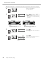
2. Switch on the power to the machine and make it ready to receive data from the computer.
➊
Press the power button.
The power comes on.
➋
Press
"EDGE."
SELECT SHEET
* ROLL
➢ Choosing "PIECE" here causes 1.6 meters of
the material to be fed out and immediately
pulled back.
ROLL:
Cutting starts at the location where the
material is secured in place.
➌
➍
Chapter 4: Performing Cutting
Press
.
The cuttable width is detected and appears
on the display.
Cutting
Cutting speed direction
Cutting
force
54
EDGE:
The material moves to the rear and cutting
starts at the leading edge of the roll.
W : 250mm
L : -----
20 cm/s
50 gf 0.250 mm
and choose "ROLL" or
A
Blade offset
Press
.
Make sure the values for the items are displayed as shown in the figure.
4-2 Using a Variety of Materials
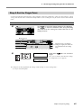
3. Check whether the material comes loose.
➊
CONDITION
Press
Press
.
.
AREA 1.0 m
Press
Press
.
.
AREA 1.0 m
0.5 m
Press
.
Use
and
to set the value
for the required length of the material.
2
1
➋
➌
2
1
2
1
3
It is a good idea to set a value that is about
0.2 meters longer than the required material
length.
Press
to enable the setting.
The set length of the material moves out to
the front, then is immediately pulled back and
taken up again.
.
➍
20 cm/s
50 gf 0.250 mm
A
Press
the figure.
to go back to the screen in
If the material comes loose from the pinch rollers, press the [PAUSE] key to stop operation. Then reload the
material, starting over from the beginning.
Be sure to check the material feed. Starting cutting without checking this first may not only make correct cutting
results impossible if a problem occurs in the material feed, but may also cause an error or malfunction, or damage
the material.
Now you're finished loading the material. After carrying out a cutting test and adjusting the blade force, you can
perform cutting.
Chapter 4: Performing Cutting
55
4-2 Using a Variety of Materials
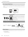
Fine-tuning the Blade Force
After you set the blade force using the [FORCE] menu, you can further fine-tune the blade force using the PEN FORCE
slider. You operate this when you want to make the blade force slightly larger or smaller than the setting made using
the menu.
Before you set the blade force using the [FORCE] menu, be sure to first move the PEN FORCE slider to its center setting
(at "0" on the scale).
(-) Smaller
Larger (+)
Adjustable range ±30 gf
➢ This value is only a suggestion.
The accuracy of the value is
not assured.
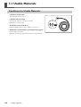
Adjusting the Cutting-in Amount
Min. 0 mm
Max. 2.5 mm
Amount of blade
extension
0.1 mm
When you want to perform accurate and fine adjustment of
the cutting-in amount, such as when cutting media with thin
carrier paper, you can obtain good results by adjusting the
tip of the blade.
Turn the cap portion of the blade holder to adjust the amount
of blade extension.
A change in extension of 0.5 mm can be made by rotating
the cap one full turn.
Rough Estimate for the Amount of Blade Extension
Use the following dimension as a rough estimate for setting the amount of blade extension.
Holder
Thickness of the
Amount of blade
Thickness of the
carrier paper
=
+
extension
media portion
2
Material
portion
Carrier-paper
portion
Blade
Half of the
carrier paper
Amount of blade is
approximately equal to
cutting-in amount
Other Features
For descriptions and more information about other features and menu items, refer to the "GX-24 Reference Guide"
(electronic-format manual).
☞ p 11 "About the Documentation"
☞ p 29 "Installing the Operation Manuals"
56
Chapter 4: Performing Cutting
Chapter 5:
Maintenance
This describes how to clean the machine and replace the blade.
57
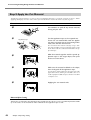
5-1 Cleaning
Before attempting cleaning, lower the loading lever and remove the material.
Clean by wiping with a cloth moistened by water then wrung dry.
Lower the loading lever.
Pinch rollers
Periodically wipe away any grime.
Display
Wipe gently with a clean, soft cloth.
Grit rollers
Use a brush to remove any buildup
of material scraps and the like.
Never use a metal brush.
Notes
➢Never use a solvent such as thinner or benzine.
➢Never attempt to oil or lubricate the machine.
CAUTION
Before attempting cleaning, switch off the power.
Sudden movement of the machine may cause injury.
58
Chapter 5: Maintenance
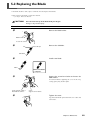
5-2 Replacing the Blade
If the blade becomes dull, replace it with the included replacement blade.
Before replacing the blade, remove the material.
☞ p 51 "Step 7: Remove the Material"
CAUTION
Do not touch the tip of the blade with your fingers.
Doing so may result in injury.
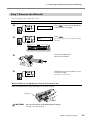
Procedure
➊
Remove the blade holder.
Blade holder
Loosen the screw.
➋
Remove the old blade.
Pin
Press this pin.
Old blade
➌
Install a new blade.
Blade
When installation
is complete
➍
Support the screw from below and insert the
blade holder.
If installed without supporting the screw in this way,
cutting quality may become poor.
Insert until the collar is
flush with the surface.
➎
Screw
Support it from below.
Tighten the screw.
Tug the blade holder upward to make sure it does not
come loose.
Chapter 5: Maintenance
59
60
Chapter 6:
What to Do If
61
6-1 What to Do If
This section describes what to do if you encounter a problem while using the machine. Refer to this first, before
assuming that a malfunction has occurred. Also, remedies
for symptoms not described here are covered in the "GX24 Reference Guide" (electronic-format manual). Refer to
it as well.
The Machine Doesn't Run
Is the power switched on?
Make sure the power button is illuminated. If the power
button is dark, press it to switch on the power.
Is the power cord connected correctly?
If it is not connected correctly, refer to the page indicated
below and connect it properly.
☞ p 22 "Connecting the Power Cord"
Is material loaded?
Check and make sure of the following two points.
• The loading lever is raised.
• The display shows the cutting conditions or the width
and length.
Is the cable used for the connection to the computer connected correctly?
If it is not connected correctly, refer to the page indicated
below and connect it properly.
☞ p 23 "Connecting to the Computer"
Are the settings for the driver correct?
Make sure the communication port is set correctly.
The Material Comes Loose during Cutting
Is the loading lever lowered?
The material is not secured in place. Make sure the pinch
rollers are inside the edges of the material and inside the
areas of the pinch-roller position-verification marks, then
raise the loading lever.
Is the material making contact somewhere while
cutting is in progress?
Make sure the edges of the material do not touch the inner surfaces of the machine during cutting. Such contact
may not only damage the material, but may make normal
material feed impossible or cause the positioning of the
material to slip.
62
Chapter 6: What to Do If
Uncut Areas Remain or Cut Edges Cannot Be Cut Cleanly
Are the blade and blade holder securely mounted?
Make sure the screw is tightened securely.
Is the tip of the blade broken?
If the blade tip is broken, then replace the blade with a
new one.
Is there any buildup of dust or material adhesive on
the tip of the blade?
Check if there are any dirty deposits on the blade. If dirty,
remove and clean the blade.
Is there any buildup of pieces of material or dust
inside the blade holder?
Take off the tip of the blade holder and remove any pieces
of material inside.
Is the blade force appropriate for the material being cut?
Carry out a cutting test and adjust the blade force until
cutting can be performed without problem.
Is the blade protector damaged or deformed?
If the blade protector is damaged, correct cutting of material may be impossible even if the machine's settings and
the installation of the blade and blade holder are all correct. If this happens, contact your authorized Roland DG
Corp. dealer or service center.
(Replacement of the blade protector is a charged service
operation.)
Chapter 7:
Appendix
63
7-1 Usable Materials
Conditions for Usable Materials
Loadable material width
50 to 700 mm (2 to 27-1/2 in.)
Loadable material length
Flat Material: 100 mm (3-15/16 in.) or more
Roll Material: no restriction
A) Cuttable material thickness
Material-portion thickness of 0.1 (0.004 in.) mm or less
B) Maximum media thickness (including backing paper)
0.3 mm (0.012 in.) or less
(Material measuring up to 1.0 mm (0.039 in.) can be loaded.)
64
Chapter 7: Appendix
A
B
7-2 Locations of the Power Rating and Serial Number Labels
Serial Number
This is required when you seek maintenance,
servicing, or support. Never peel off the label
or let it get dirty.
Power Rating
Use an electrical outlet that meets the requirements for voltage, frequency, and amperage
given here.
Chapter 7: Appendix
65
7-3 Specifications
GX-24
Driving method
Cutting method
Loadable material width
Maximum cutting area
Digital controll servo motor
Acceptable tool
Maximum cutting speed
Cutting speed
Blade force
Mechanical resolution
Software resolution
Distance accuracy (*1)
Repetition accuracy (*1) (*2)
Alignment accuracy for printing and cutting when loading printed material
Special blade for CAMM-1 series
(*1) (*3)
Media-moving method
50 to 700 mm (2 to 27-1/2 in.)
Width: 584 mm (22-15/16 in.)
Length: 24998 mm (984-1/8 in.)
500 mm/s (All direction)
10 to 500 mm/s (All direction)
30 to 250 gf
0.0125 mm/step (0.000492 in./step)
0.025 mm/step (0.000984 in./step)
Error of less than ±0.2% of distance traveled, or ±0.1 mm, whichever is greater
±0.1 mm or less
±1 mm or less for movement distance of 210 mm or less in material-feed direction and movement distance of 170 mm or less in width direction (Excluding
effects of printer and/or material)
Interface
USB interface (compliant with Universal Serial Bus Specification Revision 1.1)
Serial (RS-232C)
Replot memory
Instruction system
Power supply
800 KByte
Power consumption
Acoustic noise level During operation
During standby
Dimensions
Weight
Packed dimensions
Packed weight
Environment
Included items
Approx. 30 W (including AC adapter)
CAMM-GL III
Dedicated AC adapter
Input: AC 100 to 240 V ±10 % 50/60 Hz 1.7 A
Output: DC 24 V, 2.8 A
70 dB (A) or less (according to ISO 7779)
40 dB (A) or less (according to ISO 7779)
855 (W) X 315 (D) X 240 (H) mm (33-11/16 (W) x 12-3/8 (D) x 9-7/16 (H) in.)
16 kg (35 lb.)
1050 (W) X 450 (D) X 390 (H) mm (41-3/8 (W) x 17-3/4 (D) x 15-3/8 (H) in.)
22 kg (49 lb.)
Temperature: 5 to 40˚C (41 to 104˚F), humidity: 35 to 80% (no condensation)
AC adapter, power cord, blade, blade holder, separating knife, roller base, tweezers, test-use material, application tape, USB cable, CD-ROM, user's manual
*1
According to material and cutting conditions as specified by Roland DG Corp. (using the PNS-24 stand, sold separately).
*2
➢ Excluding material expansion and contraction.
➢ Provided that media length is under 3000 mm
*3
According to Roland DG Corp. measurement criteria.
➢ Using the included software from Roland DG Corp.
➢ Using a laser or ink-jet printer having a resolution of 720 dpi or better.
➢ Excluding glossy or laminated material.
➢ Excluding effects of printing distortion due to printer precision and effects of material expansion, contraction, or warping.
➢ Depending on the ink (black) employed by the printer used, correct sensing may not be possible.
66
Chapter 7: Appendix
Please read this agreement before opening the sealed disk package
Opening the sealed disk package implies your acceptance of the terms and conditions of this agreement.
Roland License Agreement
Roland DG Corporation ("Roland") grants you a non-assignable and non-exclusive right to use the COMPUTER
PROGRAMS in the disk package ("Software") under this agreement with the following terms and conditions.
1. Coming into Force
This agreement comes into force when you purchase and open the sealed disk package. The effective date of this
agreement is the date when you open the sealed disk package.
2. Ownership
Copyright and property of this Software, logo, name, manual and all literature for this Software belong to Roland
and its licenser. The followings are prohibited:
Unauthorized copying of the Software or any of its support files, program modules, or literature.
Reverse-engineering, disassembly, decompiling, or any other attempt to discover the source code of the Software.
3. License Restrictions
Roland does not grant you the right to sub-license, rent, assign, or transfer the rights granted under this agreement or the Software itself (including the accompanying items) to any third party.
You may not provide use of the Software through a time-sharing service and/or network system to any third party
who is not individually licensed to use this Software.
This Software may be used by one person using a single computer on which the Software is installed.
4. Reproduction
You may make one copy only of the Software for back-up purposes. The ownership of the copied Software
belongs to Roland.
You may install the Software onto the hard disk of a single computer.
5. Cancellation
Roland retains the right to terminate this agreement without notice immediately upon occurrence of any of the
following:
Violation by you of any article of this agreement
Commission by you of any serious breach of faith with respect to this agreement
6. Limitations on Liability
Roland may change the specifications of this Software or its materials without notice.
Roland shall not be liable for any damage that may be caused by the use of the Software or by exercise of the
right licensed by this agreement.
7. Governing Law
This agreement is governed by the laws of Japan, and the parties shall submit to the exclusive jurisdiction of the
courts of Japan.
R4-081203