1
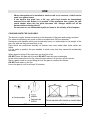
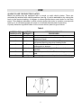
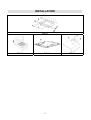
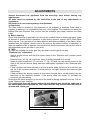
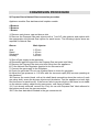
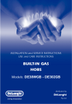
INSTRUCTIONS AND ADVICE FOR THE
USE, INSTALLATION AND MAINTENANCE
OF MIXED AND GAS FUELLED
BUILT-IN HOT PLATES
Dear Customer,
Thank you for having purchased one of our products.
We are certain that this new, modern, functional and practical appliance, built with the very
highest quality materials, will meet your requirements in the best possible way. This
appliance is easy to use. It is, however, important to thoroughly read the instructions in this
handbook in order to obtain the best results.
These instructions are only valid for the countries of destination, the identification
symbols of which are indicated on the cover of the instruction manual and on the
appliance itself.
The manufacturer shall not be held responsible for any damages to persons or
property caused by incorrect installation or use of the appliance.
This cooktop has been designed and constructed in accordance with the following codes
and specifications:
AGA101 (AS 4551) Approval Requirements for Domestic Gas cooking appliances.
AS/NZS 3350-1
General Requirements for Domestic electrical appliances.
AS/NSZ 3350-2-6 Particular Requirements for Domestic electrical cooking appliances.
AS/NSZ 1044
Electromagnetic Compatibility Requirements.
MOD.: DGHS70
The Manufacturer shall not be held responsible for any inaccuracies in this handbook due
to printing or transcription errors; the designs in the figures are purely indicative. The
Manufacturer also reserves the right to make any modifications to the products as may be
considered necessary or useful, also in the interests of the user, without jeopardizing the
main functional and safety features of the products themselves.
COD. 01050AU (b) – 03.04.2002
DESCRIPTION OF THE HOT PLATES
TYPES: PCFZ 60 V4 - PCFZ 60 N4
TYPES: PCFZ 70 V5 - PCFZ 70 N5
DGHS70
1 Ultra rapid burner of
2 Rapid gas burner of
3 Semirapid gas burner of
4 Auxiliary gas burner
5 Electric plate Ø 145 mm
6 Enamelled steel pan support 1F
7 Enamelled steel pan support 2F
8 Central enamelled steel pan support
9 Burner n° 1 control knob
10 Burner n° 4 control knob
11 Burner n° 2 control knob
12 Electric plate n° 5 control knob
13 Burner n° 3 control knob
14 Electric plate ignition warning light
15 Electric ignition button
NG
MJ/h 11.9
MJ/h 10.4
MJ/h 6.3
MJ/h 3.6
Propane Gas
11.9
10.8
6.3
3.6
This appliance must be used only for the task it has explicitly been designed for,
that is for domestic cooking of foodstuffs. Any other form of usage is to be
considered as inappropriate and therefore dangerous. Do not use this appliance as
a space heater.
2
USE
1) BURNERS
A diagram is screen-printed above each knob on the front panel. This diagram indicates to
which burner the knob in question corresponds. After having opened the gas mains or gas
bottle tap, light the burners as described below:
- Manual ignition
Push and turn the knob corresponding to the required burner in an anticlockwise direction
until it reaches the full on position (large flame fig. 1), then place a lighted match near the
burner.
- Electrical ignition
Push and turn the knob corresponding to the required burner in an anticlockwise direction
until it reaches the full on position (large flame fig. 1), then depress and release the ignition
button.
- Automatic electrical ignition
Push and turn the knob corresponding to the required burner in an anticlockwise direction
until it reaches the full on position (large flame fig. 1), then depress the knob.
- Lighting burners equipped with flame failure device
The knobs of burners equipped with flame failure device must be turned in an
anticlockwise direction until they reach the full on position (large flame fig. 1) and come to
a stop. Now depress the knob in question and repeat the previously indicated operations.
Keep the knob depressed for about 10 seconds once the burner has ignited.
Note: You are advise not to try and light a burner if the flame divider (Burner Cap) is
not correctly place.
In the event of the Burner flames being accidentally extinguished, turn off the
burner control and do not attempt to re-ignite the burner for a least 1 minute.
HOW TO USE THE BURNERS
Bear in mind the following indications in order to achieve maximum efficiency with the least
possible gas consumption:
- Use adequate pans for each burner (consult the following table and fig. 2).
- When the pan comes to the boil, set the knob to the reduced rate position (small
flame fig. 1).
- Always place a lid on the pans.
- Use only pan with a flat bottom and in thick metal.
Burners
Ultra rapid
Rapid
Semirapid
Auxiliary
Power ratings
NG
MJ/h 11.9
MJ/h 10.4
MJ/h 6.3
MJ/h 3.6
Propane Gas
11.9
10.8
6.3
3.6
Pan Ø in (cm)
22 ÷ 24
20 ÷ 22
16 ÷ 18
10 ÷ 14
WARNINGS:
- Burners with flame failure device may only beignited when the relative knob
has been set to the Full on position (large flame fig. 1).
- Matches can be used to ignite the burners in a blackout.
- Never leave the appliance unattended when the burners are being used. Make
sure there are no children in the near vicinity. Particularly make sure that the
pan handles are correctly positioned and keep a chek on foods requiring oil
and grease to cook since these products can easily catch fire.
- Never use aerosols near the appliance when it is operating.
3
USE
-
-
Where the appliance is installed in marine craft or in caravans, it shall not be
used as a space heater.
If the built-in hot plate has a lid, any spilt food should be immediately
removed from this before it is opened. If the appliance has a glass lid, this
could shatter when the hot plate becomes hot. Always switch off all the
burners before closing the lid.
Do not store or use flammable liquids or items in the vicinity of the hotplate.
COOKING HINTS FOR GAS HOBS
The burner must be chosen according to the diameter of the pans and energy required.
For optimum efficiency use a wok or pan no smaller than 230 mm diameter.
Saucepans with handles which are excessively heavy, in relationship to the weight of the
pan, are safer as they are less likely to tip.
Pans which are positioned centrally on burners are more stable than those which are
offset.
It is far safer to position the pan handles in such a way that they cannot be accidentally
knocked.
When deep fat frying fill the pan only one third full of oil.
DO NOT cover the pan with a lid and DO NOT leave the pan unattended.
In the unfortunate event of a fire, leave the pan where it is and turn off all controls.
Place a damp cloth or correct fitting lid over the pan to smother the flames.
DO NOT use water on the fire.
Leave the pan to cool for at least 30 minutes.
FIG. 1
FIG. 2
4
USE
Notes:
Use of a gas cooking appliance produces heat and moisture in the room in which it
is installed. The room must therefore be well ventilated by keeping the natural air
vents clear (fig. 3) and by activating the mechanical aeration device (suction hood
or electric fan fig. 4 and fig. 5).
Intensive and lengthy use of the appliance may require additional ventilation. This
can be achieved by opening a window or by increasing the power of the mechanical
exhausting system if installed.
Abnormal Operation:
Any of the following are considered to be abnormal operation and may require
servicing:
- Yellow tipping of the hob burner flame.
- Sooting up of cooking utensils.
- Burners not igniting properly.
- Burners failing to remain alight.
- Burners extinguished by cupboard doors.
- Gas valves which are difficult to turn.
(*) Air inlet – minimum section 100 cm2
FIG. 3
FIG. 4
5
FIG. 5
USE
2) HOW TO USE THE ELECTRIC PLATES
Mixed hot plates may be equipped with a normal or rapid electric plates. There are
controlled by switches with various positions (see fig. 6) and is switched on by turning the
knob to the required setting. A diagram is screen-printed above each knob on the front
panel. This diagram indicates to which electric plates the knob in question corresponds
(see fig. 6). A red warning light will come on to indicate that the plate is operating.
A purely indicative regulation table for the normal electric plates is given below.
TABLE
NORMAL OR
RAPID PLATE
0
1
HEAT
INTENSITY
Off
Weak
2
Low
3
Slow
4
Medium
5
Strong
6
High
POSSIBLE COOKING
PROCESSES
To dissolve butter, chocolate, etc.. To heat small
amounts of liquid.
To heat larger amounts of liquid. To prepare cremes
and suces requiring long slow cooking times.
To thaw frozen foods and prepare stews, heat to
boiling point or simmer.
To heat foods to boiling point. To brown delicate meats
and fish.
For escalopes and steaks. To simmer large amounts of
food.
To bring large amounts of liquid to the boil. For frying.
FIG. 6
6
USE
WARNINGS:
When the plate is switched on for the first time, or if it has remained unused for a
long period, it should be dried for 30 minutes on switch position n° 1. This will
eliminate any moisture that may have been absorbed by the insulating material.
To correctly use the appliance, remember:
- To place a pan on the plate before switching this on.
- To always use pans with flat and very thick bottoms (see fig. 7).
- To never use pans that are smaller than the plate diameters.
- To dry the bottom of the pan before placing it on the plate.
- Never leave the appliance unattended when the plates are being used. Make
sure that there are no children in the near vicinity. Particularly make sure that
the pan handles are correctly positioned and keep a check on foods requiring
oil and grase to cook since these products can easily catch fire.
- The plates will remain hot for a long period of time even use after use, never
touch them with the hands or other objects in order to prevent burns.
- Immediately disconnect the appliance from the electricity main as soon as
cracks are noted on the surfaces of the plates.
- If the built-in hot plate has a lid, any spilt food should be immediately
removed from this before it is opened. If the appliance has a glass lid, this
could shatter when the cooker becomes hot. Always switch off all the plates
before closing the lid.
FIG. 7
7
CLEANING
IMPORTANT:
Always disconnect the appliance from the gas and electricity mains before carrying
out any cleaning operation.
3) HOT PLATE
Periodically wash the hot plate, the enamelled stell pan support, the enamelled burner
caps “C” and the burner heads “T” (see fig. 8) with lukewarm soapy water. Following this,
all parts should be thoroughly rinsed and dried. Never wash them while they are still warm
and never use abrasive powders. Do not allow vinegar, coffee, milk, salted water, lemon or
tomato juice from remaining in contact with the enamelled surfaces for long periods of
time.
WARNINGS:
Comply with the following instructions, before remounting the parts:
- Check that burner head slots (fig. 8) have not become clogged by foreign
bodies.
- Check that enamelled burner cap “C” (fig. 8) have correctly positioned on the
burner head. It must be steady.
- The exact position of the pan support is established by the rounded corners,
which should be set towards the side edge of the hot plate.
- Do not force the taps if they are difficult open or close. Contact the technical
assistance service for repairs.
- Correctly preserve the plate after use by treating it with special products,
easily available on the market. This will keep the surface of the plate clean
and bright. The operation will also prevent the formation of rust.
CARE & MAINTAINENCE
To optimize the appearance & Upkeep of Stainless steel:
1) ALWAYS keep S/Steel out of contact from Acid / Acid-based solvent (Liquid or vapour
form).
2) After installation, wipe clean all S/Steel products with soft damp cloth to rid of any
traces of clirt (e.g. cement dust) or perspiration marks.
In the event whereby presistent sparts appear:
Immediately clean affected areas with S/Steel Cleaning Powder, using clean damp soft
cloth.
Ensure surface is rinsed and thoroughly clean of all marks and cleaning powder.
FIG. 8
8
INSTALLATION
TECHNICAL INFORMATION FOR THE INSTALLER
CAUTION:
This appliance must be installed in accordance with these installation
instructions, local gas fitting regulations, municipal building codes, water
supply regulations, electrical wiring regulations, AS5601 / AG 601 – Gas
Installations and ony other relevant statutory regulations.
This appliance shall only be serviced by authorized personnel.
This appliance is to be installed only by an authorised person.
Incorrect installation, for which the manufacturer accepts no responsibility,
may cause personal injury of damage.
Always disconnect the cooker from mains power supply before carrying out
any maintenance operations or repairs.
In the room where the cooker is installed, there must be enough air to allow
the gas to burn correctly, according to the current local regulations.
The wall and bench surfaces must be capable of sustaining temperatures of 75
degrees Celsius.
All laminates, fixing adhesive and surfacing materials should be certified suitable
for this temperature.
Refer to figure 9 - 10 for required clearances around appliance.
CLEARANCES:
Installation clearances and protection of combustible surfaces shall comply with the
current local regulations e.g. AG 601 (AS 5601) - Gas Installations code.
The installation shall comply with the dimensions in Figures 9 and 10, bearing in mind that:
A minimum clearance of 50 mm has to be kept between the bottom of the cooking
hob and the top of an appliance or a shelf.
A partition between the base of the hob and the cupboard below should be fitted
100 mm below the workbench surface if the cupboard is to be used for storage.
Overhead clearances - In no case shall the clearance between the highest part of
the hob and a range hood be less than 600 mm, or for an overhead exhaust fan,
750 mm. Any other downward facing combustible surface less than 600 mm above
the highest part of the hob shall be protected for the full width and depth of the
cooking surface area in accordance with local regulations in force. However, in no
case shall this clearance to any surface be less than 450 mm.
Side clearances - Where the dimension from the periphery of the nearest burner to
any vertical combustible surface is less than 200 mm, the surface shall be protected
in accordance with local regulations in force to a height of not less than 150 mm
above the hob for the full dimension (width or depth) of the cooking surface area.
Where the dimensions from the periphery of the nearest burner to any vertical
combustible surface is less than 200 mm, the horizontal surface shall be greater
than 10 mm below the surface of the hob, or the horizontal surface requirement
above.
Protection of combustible surfaces - Local regulations in force specify that where
required protection shall ensure that the surface temperature of the combustible
surface does not exceed 65 °C above ambient. The fixing of 5 mm thick ceramic
tiles to the surface or attaching fire resistant material to the surface and covering
with sheet metal with minimum thickness of 0.4 mm should be satisfactory.
9
INSTALLATION
4) INSTALLING THE HOT PLATE
Check that the appliance is in a good condition after having removed the outer packaging
and internal wrappings from around the various loose parts. In case of doubt, do not use
the appliance and contact qualified personnel.
Never leave the packaging materials (cardboard, bags, polystyrene foam, nails, etc.)
within children’s reach since they could become potential sources of danger.
The measurements of the opening made in the top of the modular cabinet and into which
the hot plate will be installed are indicated in either fig. 9. Always comply with the
measurements given for the hole into which the appliance will be recessed (see fig. 9 and
10).
The appliance belongs to class 3 and is therefore subject to all the provisions
established by the provisions governing such appliances.
5) FIXING THE HOT PLATE
The hot plate has a special seal which prevents liquid from infiltrating into the cabinet.
Strictly comply with the following instructions in order to correctly apply this seal:
- Detach the seals from their backing, checking that the transparent protection still
adheres to the seal itself.
- Overturn the hot plate and correctly position seal “E” (fig. 11) under the edge of the
hot plate itself, so that the outer side of the seal perfectly matches the outer
perimetral edge of the hot plate. The ends of the strips must fit together without
overlapping.
- Evenly and securely fix the seal to the hot plate, pressing it in place with the fingers.
- The prospective walls (left or right) that exceed the working table in height must be
at a minimum distance from the cutting as mentionned both in the columns and the
scheme.
- The timber barrier must be fitted below the surface of the working top leaving 50
mm clearance at the rear of the hotplate to provide ventilation (fig. 9).
COMPLY WITH THE DIMENSIONS
4 gas burner cooktops
2-3-5 gas burner cooktops
A
553
833
B
473
473
10
C
67.5
67.5
D
59.5
59.5
E
100 min.
175 min.
INSTALLATION
FIG. 9
FIG. 10
FIG. 11
11
FIG. 12
INSTALLATION
6) GAS CONNECTION
The gas connection is located in the rear and on the underside of the appliance 100 mm
from the right hand side.
1. After connecting the gas supply, check the piping and connections for leaks using a
soap and water solution. The presence of bubbles indicates a leak, tighten or replace
connections as appropriate.
Warning: Do not use any naked flame to check for leaks.
2. The operation of the appliance MUST be tested before leaving.
3. Adjust the test point pressure or supply pressure to the value which is appropriate for
the gas type.
4. Turn on the appliance gas controls and light each burner. Check for a well defined blue
flame without any yellow tipping. If any abnormality is evident then check that the burner
cap is located properly and the injector nipple is aligned correctly.
5. Check the minimum burner setting by quickly rotating the gas control knob from the
maximum to the minimum position, the flame must not go out. If adjustment is required
carry out the “minimum burner setting adjustment" procedure described below.
6. If satisfactory performance cannot be obtained, the installer shall check the installation
and notify the local gas supply authority for a gas supply problem, or if it is an appliance
problem, our Customer Service Centre should be called to obtain the nearest authorized
Delonghi Service Agent.
7. Where the appliance data plate cannot be easily read with the appliance in the installed
position the duplicate data plate must be attached to adjacent surface and the duplicate
Propane Gas conversion label should also be included where a Propane Gas conversion
has been completed.
Natural Gas
Natural Gas installation require the connection of a gas regulator at the appliance.
Assemble the regulator (noting the gas flow direction) and transition pieces (supplied with
the appliance), in accordance with figure 13.
The transition piece on the supply side of the regulator must be provided by the installer.
Propane Gas
In a Propane Gas installation the gas regulation is made at the gas cylinder and regulation
at the appliance is not required. To connect supply to the appliance use transition pieces
as shown in figure 14. These pieces are supplied with the appliance on purchase.
WARNING:
THE BURNER FLAME MUST BE ADJUSTED BY THE INSTALLER.
FAULTY INSTALLATION WILL NOT BE COVERED UNDER WARRANTY.
THIS APPLIANCE IS NOT SUITABLE FOR INSTALLATION WITH A HOSE
ASSEMBLY.
12
INSTALLATION
7) ELECTRICAL CONNECTION
The appliance is supplied with a 1800 mm long flexible supply lead.
The point of attachment for this lead is located at the rear and on the underside of the
appliance 380 mm from the right hand side.
The voltage and power consumption are detailed on the underside of the appliance.
Ensure that the appliance is correctly rated to the supply.
Connect appliance by way oa a switched power point.
THE APPLIANCE MUST BE EARTHED. Ensure that this power point is properly earthed.
Look at the connection wiring diagrams (fig. 15 - 16 - 17).
FIG. 13
FIG. 15
FIG. 14
FIG. 16
13
FIG. 17
ADJUSTMENTS
Always disconnect the appliance from the electricity main before making any
adjustments.
All seals must be replaced by the technician at the end of any adjustments or
regulations.
Our burners do not require primary air adjustment.
a) Data Label
The Data Label is located on the underside of the hotplate. A duplicate Data Label is
supplied to adhere in an accessible area next o the hotplate. This hotplate is suitable for
Natural Gas and Propane Gas; ensure that the available gas supply matches the Data
Label.
b) Before Leaving
Check that there are no gas leaks, but do not use a naked flame to detect gas leaks. Ignite
all burners to ensure correct operation of gas valves, burners, ignition and if fitted, flame
failure valves. Turn gas taps to low flame position and observe stability of the flame. When
satisfied with the hotplate, please instruct the user on the correct method of operation. In
case the appliance falls to operate correctly after all checks have been carried out, refer to
the authorised service provider in your area.
8) TAPS
Our taps are suitable for all the gas, they are male conical type at one way.
“Reduced rate” adjustment
− Switch on the burner and turn the relative knob to the “Reduced rate” position (small
flame fig. 1).
− Remove knob “M” (fig. 18) of the tap, which is simply pressed on to its rod.
− Insert a small screwdriver “D” into hole “C” (fig. 18) and turn the throttle screw to the
right or left until the burner flame has been adequately regulated to the “Reduced rate”
position.
− Check whether the flame spreads to all burner ports when the burner is lit with the gas
tap set to the minimum position. If some ports do not light, increase the minimum gas
rate setting.
− Check whether the burner remains lit even when the gas tap is turned quickly from the
maximum to the minimum position. If the burner does not remain lit, increase the
minimum gas rate setting.
Check that the flame does not go out when the knob is sharply switched from the “Full on”
to the “Reduced rate” position.
It is understood that only burners operating with Natural gas should be subjected to
the above mentioned adjustments. The screw must be fully locked when the burners
operate with Liquid gas.
FIG. 18
14
CONVERSION PROCEDURE
9) Propane Gas to Natural Gas conversion procedure
Appliance models: Gas stainless steel hotplate models:
4 Burners
2 Burners
1 Burner
1. Remove each burner cap and burner skirt.
2. Remove the Propane Gas main injector with a 7 mm/VF tube spanner and replace with
the appropriate size Natural Gas injector for each burner. The following injector sizes are
required for Natural Gas:
Burner
Main injector
Wok
Rapid
Semirapid
Auxiliary
1.55 mm
1.45 mm
1.12 mm
0.85 mm
3. Shut off gas supply to the appliance.
4. Disconnect gas inlet pipe from the Propane Gas test point inlet fitting.
5. Remove the Propane Gas test point inlet fitting from the appliance.
6. Fit the Natural Gas Regulator supplied in the conversion kit.
7. Connect the gas supply to the Regulator.
8. Check for gas leaks. Do not use a naked flame to check for gas leaks.
9. Adjust the gas pressure to 1.00 kPa with the two semi-rapid (SR) burners operating at
the maximum.
10. Remove the control knob, with a thin shaft blade screwdriver down the centre of each
gas valve shaft, screw the by-pass injector anti-clockwise. Test the appliance on both high
and low flame for each burner. If the burner fails to remain alight or the flame is not stable
on the simmer setting, adjust the by-pass screw, until flame is stable.
11. If not already removed, remove the “Only for use with Propane Gas” label adhered to
the bottom panel near the gas connection.
12. Fit the new data label included in the gas conversion kit.
15
CONVERSION PROCEDURE
10) Natural Gas to Propane Gas conversion procedure
Appliance models: Gas stainless steel hotplate models:
4 Burners
2 Burners
1 Burner
1. Remove each burner cap and burner skirt.
2. Remove the Natural Gas main injector with a 7 mm/VF tube spanner and replace with
the appropriate size Propane Gas main injector for each burner. The following injector
sizes are required for Propane Gas:
Burner
Main injector
Wok
Rapid
Semirapid
Auxiliary
0.95 mm
0.91 mm
0.70 mm
0.53 mm
3. Remove the control knob, with a thin shaft blade screwdriver down the centre of each
gas valve shaft, screw the by-pass injector fully clockwise.
4. Shut off gas supply to the appliance.
5. Disconnect gas inlet pipe from the Natural Gas Regulator.
6. Remove the Natural Gas Regulator from the appliance.
7. Fit the Propane Gas test point inlet fitting supplied in the conversion kit.
8. Connect the gas supply to the inlet fitting.
9. Check for gas leaks. Do not use a naked flame to check for gas leaks.
10. Adjust the gas pressure to 2.75 kPa.
11. Test the appliance on both high and low flame for each burner and check the gas
pressure. If the burner fails to remain alight or the flame is not stable on the simmer
setting, adjust the by-pass screw, until flame is stable.
12. If not already removed, remove the “Only for use with Natural Gas” label adhered to
the bottom panel near the gas connection.
13. Fit the new data label included in the gas conversion kit.
16
CONVERSION PROCEDURE
BURNER ARRANGEMENT ON THE HOT PLATE
TABLE
BURNERS
N°
GAS
DESCRIPTION
1
ULTRA RAPID
2
RAPID
3
SEMIRAPID
4
AUXILIARY
PROPANE
NATURAL
PROPANE
NATURAL
PROPANE
NATURAL
PROPANE
NATURAL
NORMAL
PRESSURE
INJECTOR
DIAMETER
(kPa)
2.75
1.00
2.75
1.00
2.75
1.00
2.75
1.00
(1/100 mm)
95
155
91
145
70
112
53
85
FIG. 19
17
NOMINAL
HEAT INPUT
(MJ/h)
MAX.
11.9
11.9
10.8
10.4
6.3
6.3
3.6
3.6
SERVICING
WARNING:
Servicing should be carried out only by an Authorized person/Service agent.
11) COMPONENTS REPLACEMENT
NOTE:
BEFORE ANY MAINTENANCE REQUIRING REPLACEMENT OF A COMPONENT IS
UNDERTAKEN ENSURE THAT THE ELECTRICAL LEAD HAS BEEN ISOLATED AND
REMOVED FROM THE POWER POINT.
To replace the components fit inside the hob is necessary to take off the pan supports and
the burners from the upper part of the working table, then unscrew the burner fixing screws
“V” (fig. 20) and the control knobs, fixed by a simple pressure, in order to take off the
working table.
After having carried out the above listed operations, the burners (fig. 21), taps (fig. 22) and
electrical components can all be replaced (fig. 23).
It is advisable to change seal “D” each time a tap is changed in order to ensure a perfect
tightness.
Greasing the taps (see fig. 24 - 25)
If a tap becomes stiff to operate, it must be immediately greased in compliance with the
following instructions:
- Remove the tap.
- Clean the cone and its housing using a cloth soaked in diluent.
- Lightly spread the cone with the relative grease.
- Fit the cone back in place, operate it several times and then remove it again.
Eliminate any excess grease and check that the gas ducts have not become
clogged.
- Fit all parts back in place, complying with the demounting order in reverse.
To facilitate the servicing technician’s task, here is a chart with the types and sections of
the powering cables and the ratings of the electrical components.
FIG. 20
FIG. 21
FIG. 22
FIG. 23
FIG. 24
FIG. 25
18
SERVICING
CABLE TYPES AND SECTIONS
TYPE OF
HOT PLATE
Gas hot plate
Mixed hot plate
electrical plate
with
1
TYPE OF
CABLE
SINGLE - PHASE
POWER SUPPLY
H05 RR - F
Section 3 X 0.75 mm2
H05 RR - F
Section 3 X 1 mm2
ATTENTION!!!
If the power supply cable is replaced, the installe should leave the ground wire
longer than the phase conductors (fig. 26) and comply with the recommendations
given in paragraph 7.
If the supply cord is damaged it must be replaced by the manufacturer or it’s
Service Agent or a similarly qualified person in order to avoid a hazard.
POWER RATINGS OF THE ELECTRICAL COMPONENTS
TYPE
DIAMETER
POWER RATING (W)
Normal plate with 7 positions with the
protector
145
1000
Rapid plate with 7 positions
145
1500
FIG. 26
19
SERVICE AND MAINTENANCE
If the ignition spark fails to ignite or does not light the gas, check the following items before
calling our Customer Service Centre to obtain the nearest Authorised Delonghi Service
Agent:
Burner is reassembled and located correctly.
Spark electrode and white ceramic are clean and dry.
240 VAC power supply is connected.
Contact the local gas utility or our Customer Service Centre to obtain the nearest
Authorized Delonghi Service Agent.
You can smell gas when all burners are turned on.
The burners do not remain alight at the minimum marked setting.
The burner flame is yellow or emits an unusual odour.
Note that a bi-annual inspection of the appliance by an authorized service agent or your
locate gas utility will ensure many years of trouble free operation of your appliance.
Servicing the appliance:
Service may be obtained by contacting our Customer Service Centre to locate the nearest
Authorised Delonghi Service Agent.
Descriptions and illustrations in this booklet are given as simply indicative. The manufacturer reserves the right,
considering the characteristics of the models described here, at any time and without notice, to make eventual necessary
modifications for their construction or for commercial needs.
20