1
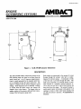
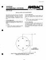
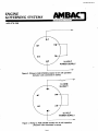
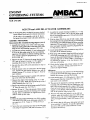
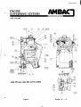
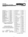
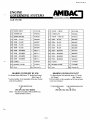
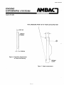
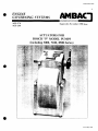
Section EG 60-4
SECTION
ENGINE
G 0 VERNING
S YS TEMS
IE_T
AGB 270
AGB 280
EG 60-5A
E R
N
A T l O
Supersedes
N
A
November
L
1990 Issue
ACTUATORS FOR
BOSCH "P" MODEL PUMPS
(including 3000, 7100, 8500 Series)
lssved May 1995
Section EG 60-4
SECTION
ENGINE
GOVERNING
EG 60-5A
SYSTEMS
INTERNATIONAL
AGB
270/280
INTRODUCTION
The AGB 270/280 actuators are linear electromagnetic throttle positioning devices which mount integral to Robert Bosch (RB) 3000, 7100, and 8500 series "P" model fuel injection pumps. They may also
be utilized on other types of in-line fuel injection
pumps with the use of an interface plate. They position the engine fuel throttle according to the amount of
current flowing from the speed control unit through
the actuator.
An external fuel shutoff lever is available for emergency engine shutdown.
The complete
family of speed control units is suitable for use with
the AGB 270/280 series actuators and will provide
other governor system fail-safe features.
The significant features of an engine governing system
utilizing the integral actuator are the elimination of external fuel system control linkage and engine actuator
brackets. The actuator requires no engine drive for
hydraulic input. It is designed to have no sliding parts
or gears, requires no maintenance and typically outlasts the life of the engine. The system provides the
utmost in performance because the fuel injection pump
rack is directly connected to the actuator, thus minimizing delays and ensuring fast response. It is completely self-contained except for the wires connecting
it to the speed control unit.
SPECIFICATIONS
POWER INPUT
- Operating Voltage .........................................................................................
Normal Operating Current ................................................................................
Maximum Current (Instantaneous)
......................................................................
12, 24 or 32 VDC
5 amps at 12 VDC
2.5 amps at 24 or 32 VDC
8 amps at 12VDC
4 amps at 24 or 32 VDC
ENVIRONMENTAL
Temperature Range ....................................................................
-54 ° to + 93°C (-65 ° to + 200°F)
Relative Humidity ..................................................................................................
up to 100%
- Case ....................................................................................
Fungus proof and corrosion resistant
PHYSICAL
- Dimensions .............................................................
Metric design to match fuel pump (See Figure 1)
- Weight .........................................................................................................
3.75 kgs (8.3 lbs)
- Mounting ..................................
Integrally mounted on the rear of the RB "P" model fuel injection pumps
directly replacing the existing mechanical governor (See ASSEMBLY, Page 5)
MATING
CONNECTOR
For actuator only .......................................................................................
EC 1249-2 (6 pins)
Wiring harness to CU671C (includes both connectors prewired) ...............................................
CB679
Harness to CU673C series speed control units ..................................................................
CB6711A
OPTIONAL ACTUATORS
AGB 270A1 ..............................................
AGB 270B1 ..........................................
AGB 280A1 ....................................................
- AGB 280B1 .................................................
Bosch "P" model 7100/8500 series, with temperature probe
(comprises Kits K6736 and KT 6737)
Bosch "P" model 7100/8500 series, without temperature probe
(comprises Kits K6739 and KT 6737)
Bosch "P" model 3000 series, with temperature probe
(comprises Kits K6736 and KT 6738)
Bosch "P" model 3000 series, without temperature probe
(comprises Kits K6739 and KT 6738)
Page
1
Section EG 60-4
SECTION
ENGINE
GOVERNING
EG 60-5A
SYSTEMS
[INTERNATIONAL
AGB
270/280
130mm
5.125"
143mm
f
5.625"
203mm
gg
EG-195
102mm
4.0625"
Figure
1.
AGB
270/280
actuator
dimensions
DESCRIPTION
The AGB 270/280 actuator controls the position of the
fuel injection pump rack based on an input from the
speed control unit. An AC frequency signal (proportional to speed) generated by the magnetic speed sensor is constantly fed into the speed control unit. The
signal is compared with the present frequency (speed
setting). If the frequencies are not identical, a change
in current from the speed control unit changes the
magnetic force in the actuator. The change causes an
angular rotation of the actuator shaft and linear repositioning of the fuel injection pump racks,
Page
Rack position is proportional to the amount of current
flowing through the actuator coils and is counterbalanced by internal springs. A mechanical override
of the fuel rack is provided through the shaft. This
shaft can be connected to an external electric or pneumatic solenoid or a manually operated shutdown device to move the fuel rack to the no-fuel position and
hence shut down the engine. The actuator housing is
sealed against engine environment with gaskets at all
openings so steam or other water based cleaning will
not affect the system's operation. No maintenance is
necessary.
2
Section EG 60-4
SECTION
ENGINE
GOVERNING
EG 60-5A
SYSTEMS
[ INTERNATIONAL
AGB 270/280
INSTALLATION AND ADJUSTMENTS
The leads from the speed control unit to the actuator
should be at least #18 for 24 volt and 32 volt and #16
wire for 12 volt operation. Large gauge wire is necessary for long wire lengths to compensate for current
losses.
24 VOLT OPERATION
Connect the following actuator terminals together with
jumpers at the mating half of the connector (See Figure
3).
1. B to C
2. A & D to their respective terminals at the control
unit. (See Control unit instructions.)
12 VOLT OPERATION
Connect the following actuator terminals together with
jumpers at the mating half of the connector (See Figure 2).
1. A to C
2. B to D
3. A & D to their respective terminals at the speed
control unit. (See control unit instructions.)
32 VOLT OPERATION
To use with 32 volt supply, wire the connector as for 24
volt operation but add a 1.5 ohm, 25 watt resistor or a 2
ohm, 50 watt adjustable resistor, set to 1.5 ohms. Then
wire the resistor in series with terminal A of the actuator
(see Figure 4).
12 VOLT
POWER SUPPLY
Figure 2. Wiring to AGB 270/280 actuator for 12 volt operation
(Actuator coils connected in parallel)
Page
3
Section EG 60-4
SECTION EG 60-5A
F-_N T E R N A T I O N A
AGB 2,70/280
1
_
Figure
3. Wiring to AGB 270/280 actuator for 24 volt operation
(Actuator coils connected
in series)
1.5 OHM
25 WATT
A
32 VOLT
POWER SUPPLY
Figure 4. Wiring to AGB 270/280 actuator for 32 volt operation
(Actuator coils connected in series)
Page 4
Section EG 60-4
SECTION
--
ENGINE
GOVERNING
SYSTEMS
IN
AGB
EG 60-5A
TERN
A
IONA
L
270/280
AGB 270 and AGB 280 ACTUATOR ASSEMBLIES
Note: (I) If fuel pump has a mechanical governor attached,
consult Robert Bosch agent for removal instructions.
12. Assemble the actuator housing assembly (1), 'o' ring
(104) and sealing gasket (114) to the fuel pump using
(II) In order to be compatible with the R. Bosch
fuel pump this actuator is built with metric hardware.
the two top mounting capscrews (110) and lockwashers
(111 ) loosely fitted.
ASSEMBLY PROCEDURE:
"-_
Measurements fRef. Assembly Drawings Figures 5, 6 & 7)
1. Assemble the bearing cover (201) to the fuel pump
without the sealing gasket (202) or the shims (203)-(206),
using the two top mounting capscrews (211) only.
13. With the shims (204) from step (4) held in place, align
the locating hole in the actuator housing (1) with the pin
in the bearing cover (200) and fasten the lower mounting
capscrews (112) and washers (113) in place. Torque the
lower and upper mounting capscrews progressively to
7-9 Nm (9.5-12.3 lbs. ft.).
2. Assemble the housing assembly (1) and sealing gasket
(114) to the fiiel pump using the two top mounting
capscrews (110) and the two bottom mounting capscrews
(112). Torque capscrews progressively to 7-9 Nm
(9.5-12.3 lbs. ft.).
3. Measure the gap 'D' between the pump bearing cover
(201) and the actuator housing (1). The supplied
mounting shims may be used for this purpose.
14. Locate spring adjuster (106) and shutdown stop (105) in
link (103) to the retracted position.
15. With spring (109) installed, clamp link (102) and rod end
(24) to rack connecting link (103) with capscrew (116).
Access for the socket headed capscrew is through the tA
inch pipe plug hole as shown. Note: A lockwasher is
not required for capscrew (116), the threads in link
(103) are self-locking.
4. Set aside the shims (207)-(210) determined in step (3)
for later use.
16. Check that the linkage slides (freely without any binding. This is important, binding could cause loss of
control and engine damage.
5. With the actuator rotor not connected to the fuel pump
rack, measure the gap between actuator rotor and the
actuator housing 'E' as shown on Figure 5. Note for
later reference,
6. Remove the actuator housing (1), gasket (114) and bearing cover (201) from the fuel pump.
7. Measure the depth of the bearing cavity 'A' in the
bearing cover (201). Note: This is from the tips of the 4
pump contacting feet. Ref. Fig. 7.
8. Measure the protrusion of the fuel pump camshaft bearing
'B' from the pump face. Ref. Fig. 6.
9. Subtract 'B' from 'A'. This is the amount of shims needed
for zero clearance between the bearing cover and the
bearing. Select a combination of supplied shims (203)(206) to make up this value.
Assembly
10. Mount the gasket (202) and bearing cover (201) complete
with shims (203)-(206) to the fuel pump using the two
top capscrews (211). Torque to 7-9 Nm (9.5-12.3
Ibs. ft.).
Adjustments
17. With the fuel pump rack pushed to its full fuel position
towards the front of the fuel pump, measure the gap 'E'
between the actuator rotor and the housing.
18. Check that this gap is .25 (.010 inches) to 1.0mm (.040
inches) greater than that measured in step (5), i.e.,
rack travel is not restricted.
19. The gap can be adjusted by removing capscrew (25),
loosening rod end locknut (26) and rotating the outer
half of the rod end assembly (8) in steps ofhalfa turn.
Check to be sure that the rod end bearings are properly
aligned to avoid binding when the actuator moves and
lock in this position using locknut (26).
20. With the fuel pump rack pushed in to the full fuel
position, adjust the shutdown stop screw (105) so that
shutdown lever (10) can be rotated against its return
spring with approximately 1/_
mm (.010 inches) of free
play.
21. This ensures that the full power fuel pump rack travel
is not restricted. If required, for specific applications,
the screw (105) can be turned clockwise to limit
maximum fuel delivery.
11. Secure the rack connecting link (102) to the fuel pump
rack using two capscrews (108) and lockwashers (107).
Page
5
Section EG 60-4
SECTION
ENGINE
GOVERNING
EG 60-5A
SYSTEMS
[INTERNATIONAL
AGB 270/280
22. A low fuel stop screw (117) is also available to limit
the fuel rack cut-off position if required. After adjustmerit, lock the screw with nut (118). Torque to 2 Nm
(2.7 lbs. ft.).
23. The linkage may be further optimized after the complete
governor system is installed and wired by temporarily
inserting an ammeter is one of the wires between the
speed control unit and the actuator. Measure the
actuator current at no load and at full load. The current
required for any governing condition indicates the
actuator position to satisfy that condition. It is desirable
to have more than 1 amp current difference indicating
actuator movement, no load to full load. A suggested
range of current values are given below which will
ensure adequate current spread to ensure stable governor
operation. The current values correspond to 80 of
actuator travel.
No Load
Full Load
AGB 250 Actuator
12 Volt
24 Volt
2.0 amps
1.0 amps
5.0 amps
2.5 amps
The current can be adjusted by turning adjusting screw
(106). Turning the screw counter-clockwise will reduce
the current flow and vice versa.
24. Assemble cover (2) and gasket (3) to the actuator
using two drilled hex head screws (30) and lockwasher
(5) at cover top locations.
Note: Drilled heads provide for lockwiring a seal to
screws after the actuator is assembled and
adjusted. Complete cover assembly using four
hex head screws (4) and lockwashers (5). Torque
all six screws to 4-5 Nm (5.5-6.75 lb. ft.).
Page 6
Section EG 60-4
SECTION
_-
ENGINE
GO VERNING
SYSTEMS
r_-__
R
N
A
T I O
N
A L
AGB 270/280
Figure 5.
Section "A" - "A"
Page 7
EG 60-5A
I
Section EG 60-4
SECTION EG 60-5A
ENGINE
GOVERNING
SYSTEMS
[_N
TERNATIONAL
AGB 270/280
118
NUT, HEX
1
NT403241
30
SCREW, HEX HD.
2
SC403031
117
116
SCREW, SOC. HD.
SCREW, BUTTON HD.
1
1
SC403242
SC410598
29
NUT, LOCKING
1
NT410607
28
BEARING
2
BG410587
WASHER,
2
1
WA403175
GA410454
PLUG, PIPE
NUT, HEX
1
1
PG400718
NT406736
115
FLAT
114
GASKET
113
LOCKWASHER
2
WA407649
27
26
112
SCREW,
2
SC403165
25
SCREW, BUTTON HD.
1
SC410597
111
LOCKWASHER
2
WA2012-6M
24
BEARING,
1
BG410416
110
SCREW, SOC. HD.
2
SC406508
23
109
SPRING
1
SP403228
22
SOLDER
AR
BM403010
108
107
SCREW, SOC. HD.
LOCKWASHER
2
2
SC406"494
WA2012-5M
21
CLEANER
AR
BM403011
106
SCREW, SPRING ADJUST
1
SC410450
20
LEVER ASSY., SHUT OFF
1
LE410413
105
104
SCREW, HEX SOCKET
'O' RING
1
1
SC410434
GA410588
19
RING, RETAINING
2
RG403067
18
WASHER,
2
WA410417
103
HOLDER ASSY.
1
HP410445
17
SHAFT,
102
LINK, RACK CONNECTING
1
LK410641
16
TUBING,
101
SEAT, SPRING
1
GU410438
15
Pos.
Name
Drawing No.
HEX HD.
Qty.
LOOSE PARTS FOR MOUNTING
ASSEMBLY
TO THE FUEL
HOUSING
KT 6739
HG 412131
1
SH410451
4
TU403133
LOCKWASHER
4
WA406091
14
SCREW
4
SC403096
13
__
12
GASKET
I
GA403094
CONNECTOR
i
EC403089
11
SPRING,
STOP LEVER
1
SP410472
10
LEVER,
INNER. STOP
1
LE410471
1
PN400008
l
BG410415
2
PG410440
.625 LG.
KITS
8
BEARING,
(Ref. Figure 5)
7
PLUG,
6
5
SEAL OIL
LOCKWASHER
2
6
SE410412
WA407648
4
SCREW,
HEX HD.
4
SC403020
3
GASKET,
COVER
1
GA403234
2
1
COVER
HOUSING
ASSY.
1. CV403015
1 See "Tabulation"
assembly kit
on Page 1)
TABULATION
Housing Assy.
HG 410082
LEVER
ROLLPIN
Note: Actuator assembly consists of housing
plus bearing cover kit (see SPECIFICATIONS
Kit Number
KT 6736
PLAIN
9
ASSEMBLY
KT 6736 and KT 6739
HOUSING
PUMP
ROD END
For Actuator
AGB270A1
/ AGB280AI
AGB270B1
/ AGB280B1
Pos.
ROD END
EXPANSION
Name
Qty.
PRE-ASSEMBLED
P:Jgc
Drawing
HOUSING
No.
Section EG 60-4
SECTION EG 60-5A
ENGINE
GOVERNING
SYSTEMS
_'-'_'T'-_'R-N
A T I O N A L
AGB 270/280
"--
213
SCREW-DRIVE
2
SC150-3BL
213
SCREW--DRIVE
2
SC150-3BL
212
NAMEPLATE
1
NP410442
212
NAMEPLATE
1
NP410441
211
SCREW-HEX
2
SC403162
211J SCREW -- HEX HD.
2
SC403162
210
SHIM -- PLATE
1
SR410098
210
SHIM -- PLATE
l
SR410098
209
SHIM -- PLATE
1
SR410097
209
SHIM -- PLATE
1
SR410097
208
SHIM -- PLATE
2
SR410096
208
SHIM -- PLATE
2
SR410096
207
SHIM -- PLATE
2
SR410095
207
SHIM -- PLATE
2
SR410095
206
SHIM -- BE.ARING
3
SR6715-4
206
SHIM -- BEARING
3
SR410429
205
SHIM -- BEARING
1
SR6715-3
205
SHIM -- BEARING
1
SR410428
204
SHIM -- BEARING
3
SR6715-2
204
SHIM -- BEARING
3
SR410427
203
SHIM -- BEARING
2
SR6715-1
203
SHIM -- BEARING
2
SR410426
202i GASKET
1
GA410435
202
GASKET
1
GA410436
_.01 BEARING COVER
1
CV410091
201
BEARING COVER
1
CV410090
Drawing No.
Pos.
Name
Pos.
HD.
Name
Qty.
BEARING COVER KIT KT 6738
For Robert
Bosch 3000
Series "P" Model
*A typical number on the nameplate
would read as follows:
Drawing No.
BEARING COVER KIT KT 6737
Fuel Pumps*
For Robert Bosch 7100 and 8500 Series "P" Model
(Ref: Figure 5)
of this type of pump
Fuel Pumps*
*A 13,pical number on the nameplate
would read as follows:
"P" SIZE DESIGNATION
"P" SIZE DESIGNATION
PES 6P ll0A 720/3 RS3036
(Note:
Qty.
(Ref: Figure 5)
of this type of pump
"7100" SERIES DESIGNATION
PES 6P ll0A 720/3 R $7136
This does not include 7100 and 8500 series
which uses Kit KT 6737).
Page 9
Section EG 60-4
SECTION
ENGINE
GOVERNING
EG 60-5A
SYSTEMS
I.N
T E R N
A
T I O
N A
L
AGB 270/280
NOTE:
MEASURE
FROM
TOP OF FOUR
CONTACTING
FEET
- PUMP FACE
--1
,,AIBEARING
@
--_
Figure
B _DIMENSION
\
6. Protrusion
measurement
of Pump Cam Bearing
\
EARING
COVER
Figure
Pagc
]0
7. Depth
measurement