1
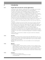
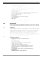
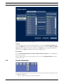
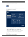
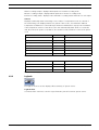
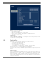
Divar XF
Digital Hybrid Recorder
en
User manual
Divar XF
Table of Contents | en
3
Table of Contents
1
Introduction
5
1.1
Digital video recorder for security applications
5
1.1.1
Versions
5
1.1.2
Manuals
5
1.1.3
Features
5
1.1.4
On-screen help
6
1.2
Unpacking
6
1.2.1
Package contents
6
1.3
Installation environment
7
1.3.1
Mounting
7
1.3.2
Ventilation
7
1.3.3
Temperature
7
1.3.4
Power Supply
7
1.4
Associated equipment
7
2
Quick install
9
2.1
Connections
9
2.1.1
Primary connections
9
2.1.2
Optional connections
9
2.1.3
Powering up
9
2.2
First-time use
9
2.3
Quick install menu
10
2.3.1
International
10
2.3.2
Schedule
10
2.3.3
Recording
10
2.3.4
Network
10
3
Operating instructions
13
3.1
Front panel controls
13
3.1.1
Keys
13
3.1.2
Indicators
15
3.2
Mouse Controls
15
3.3
Viewing pictures
16
3.3.1
Monitor A
16
3.3.2
Monitor B
16
3.3.3
Viewing
16
3.4
Live and playback
18
3.4.1
Live mode
18
3.4.2
Accessing playback functions
18
3.4.3
Playback mode
18
3.5
Overview of the menu system
19
3.5.1
Access using the front panel keys
20
3.5.2
Access using the mouse
20
3.5.3
Access using the Intuikey keyboard
20
3.6
Search
20
3.6.1
Date/time search
21
Bosch Security Systems
User manual
F.01U.135.431 | 2.5 | 2009.08
4
en | Table of Contents
Divar XF
3.6.2
Event search
21
3.7
Export
23
3.8
Configuration
24
3.8.1
Monitor settings
24
3.9
System information
25
3.9.1
Status
26
3.9.2
Logbook
27
3.10
Event handling
28
3.10.1
Alarms
29
3.10.2
Contact inputs
30
3.10.3
Motion events
30
3.10.4
Video loss alarm
30
F.01U.135.431 | 2.5 | 2009.08
User manual
Bosch Security Systems
Divar XF
Introduction | en
1
Introduction
1.1
Digital video recorder for security applications
5
The Divar XF is a video and audio recording system that records multiple camera and audio
signals while simultaneously providing live multiscreen viewing and playback.
The unit has comprehensive search and playback facilities for viewing stored video. Once
configured, all recording takes place in the background without requiring operator
intervention. Maximum recording rates of 30 (NTSC) and 25 (PAL) images per second, per
channel, are guaranteed. The recording rate and quality are selectable per camera. Up to four
internal hard disks can be used to provide various storage capacities for recording.
All models have extensive alarm handling functions and telemetry control. Alarm functions
include motion detection in user-definable areas of the image on any camera input.
The unit can be easily operated and programmed via the front panel control keys, mouse, and
the on-screen display menu system. Two monitor outputs provide full-screen, quad, and
multiscreen viewing. Connect a KBD (Intuikey) keyboard for PTZ control and to improve the
ease-of-use.
Looping auto-terminating video inputs and outputs, audio inputs and outputs, alarm inputs
and outputs, and remote control connectors are on the rear panel. Two VGA connectors
provide outputs for an A and a B monitor. CVBS and Y/C video outputs in either NTSC or PAL
are also provided. Monitor A displays full-screen or multiscreen digital pictures that can be
frozen and zoomed. Monitor B displays live full-screen or multiscreen pictures.
Use the Control Center PC-application via a network for live viewing, playback, and
configuration. Five simultaneous users can control multiple Divar XFs. The Divar XF includes
an authenticity check for both local and remote playback. A dedicated PC player is provided
for playback of secure video files. The PC-based Configuration Tool facilitates the installation
of the unit.
An SDK (software development kit) is available to integrate the Divar XF into third party
management software.
1.1.1
Versions
There are various Divar XF models; 8-channel and 16-channel with DVD burner option, each
with various storage capacities. Both 8-channel and 16-channel versions operate in exactly the
same way except that fewer camera, audio, and alarm inputs are present, and the number of
available multiscreen views differs.
Optionally, up to 8 IP cameras can be connected (in addition to the 8 or 16 analog input
channels).
1.1.2
Manuals
Four manuals are supplied:
–
Installation manual - a detailed description for installers on how to install the product.
–
Quick Installation guide - gives a brief overview on how to set up and install the product.
–
Operation manual - a detailed description for end-users on how to operate the unit.
–
Control Center and Archive Player operation manual - a detailed description for end-users
and administrators on how to set up and operate the Control Center and Archive Player
software.
1.1.3
Features
The Divar XF has the following features:
Bosch Security Systems
–
8 or 16 looped-through, auto-terminating camera inputs
–
8 or 16 audio inputs
User manual
F.01U.135.431 | 2.5 | 2009.08
6
en | Introduction
1.1.4
Divar XF
–
Support for up to eight IP cameras (optional)
–
Simultaneous recording and playback
–
Internal hard disk video storage (front replaceable)
–
On-board RAID4 (optional)
–
10/100Base-T Ethernet port for Ethernet connection and networking
–
Two RS232 serial ports for serial communication
–
External KBD keyboard input
–
Dual monitor outputs
–
Full-screen and various multiscreen display capabilities in live and playback modes
–
Spot monitor output with sequencing, multiscreen, and OSD
–
Two audio outputs (dual mono)
–
Motion detection
–
8 or 16 switching (alarm) inputs and 4 alarm outputs
–
Video loss detection
–
Audible alarm
–
Pan, tilt, and zoom camera control via RS485 and biphase
–
Local archiving via USB
–
Local archiving via built-in DVD burner (optional)
On-screen help
On-screen context-sensitive help is available for some topics. Just press the help button to
see the help text associated with your current activity. Press the escape button to exit help.
1.2
Unpacking
Check the package for visible damage. If any items appear to have been damaged in shipment,
notify the shipping company. Unpack carefully. This is electronic equipment and should be
handled with care to prevent damage to the unit. Do not attempt to use the unit if any
components are damaged. If any items are missing, notify your customer service
representative or Bosch Security Systems sales representative. The shipping carton is the
safest container in which to transport the unit. Save it and all packing materials for future use.
If the unit must be returned, use the original packing materials.
1.2.1
Package contents
Check for the following items:
–
Digital Video Recorder (Divar XF 16 or Divar XF 8 unit)
–
USB mouse
–
Quick installation guide
–
Divar XF operation manual
–
Divar XF Control Center and Archive Player operation manual
–
Installation manual (this manual)
–
A 25-pin D-type switching and alarm connector board
–
A 15-pin D-type connector board (used for Biphase PTZ connections)
–
A 3-pin screw terminal connector (used for RS485 PTZ connection)
–
Power supply cord
–
Shielded network cross-over cable (for service and testing purposes)
–
Rack mounting kit
–
A CD-ROM containing the software and manuals
F.01U.135.431 | 2.5 | 2009.08
User manual
Bosch Security Systems
Divar XF
Introduction | en
1.3
Installation environment
1.3.1
Mounting
7
The Divar XF is supplied as a desktop unit. If desired, the unit can be rack mounted using the
rack mounting kit supplied with the unit.
1.3.2
Ventilation
Ensure that the location planned for the installation of the unit is well ventilated. Take note of
the locations of the cooling vents in the unit's enclosure and ensure that they are not
obstructed.
1.3.3
Temperature
Observe the unit's ambient temperature specifications when choosing an installation space.
Extremes of heat or cold beyond the specified operating temperature limits may cause the
unit to fail. Do not install the unit on top of hot equipment.
1.3.4
Power Supply
Ensure that the site's AC power supply is stable and within the rated voltage of the unit. If the
site's AC power is likely to have spikes or power dips, use power line conditioning or an
uninterrupted power supply (UPS).
1.4
Associated equipment
A typical system could contain the following components (not included with the unit):
–
A primary monitor for multiscreen monitoring (monitor A)
–
A second monitor for spot/alarm monitoring (monitor B)
–
Cameras with 1 Vpp composite video outputs
–
IP cameras (see datasheet for supported models)
–
Amplified microphone(s)
–
Audio amplifier with speaker(s)
–
Video coaxial cable with BNC connectors for connecting the video signals
Audio cable with RCA connectors for connecting audio signals.
–
AC power supply outlet for the unit that allows for secure isolation (the unit has no on/
off switch for security reasons)
Bosch Security Systems
–
A KBD keyboard
–
PC for Control Center and Configuration Tool applications
–
Pan/tilt/zoom control units
User manual
F.01U.135.431 | 2.5 | 2009.08
8
en | Introduction
F.01U.135.431 | 2.5 | 2009.08
Divar XF
User manual
Bosch Security Systems
Divar XF
2
Quick install | en
9
Quick install
To get the unit quickly operational, make the connections described below and then enter the
relevant data in the Quick install menu. The Quick install menu appears the first time the unit
is started. When the relevant information is entered, the unit will be operational.
2.1
Connections
Figure 2.1 Back panel connections
2.1.1
2.1.2
Primary connections
1.
Connect the cameras to the BNC camera inputs (automatically terminated).
2.
Connect monitor A to the BNC, Y/C, or VGA (supporting 1280x1024) output MON A.
3.
Connect (supplied) USB mouse to a USB port.
Optional connections
4.
Connect monitor B to the BNC, Y/C, or VGA (supporting 1024x768) output MON B.
5.
Connect up to 16 audio signals to the RCA audio inputs.
6.
Connect the RCA audio output(s) to the monitor or an audio amplifier.
7.
Connect up to 16 (alarm) inputs (via the supplied 25-pin D-type connector board).
8.
Connect up to 4 alarm outputs (via the supplied 25-pin D-type connector board).
9.
Connect the malfunction output (via the supplied screw terminal adapter).
10. Connect an Intuikey keyboard to the KBD In socket and connect the terminator (supplied
with the keyboard) to the KBD Out socket.
11. Connect a Bosch pan/tilt/zoom control unit to the Biphase port (via the supplied 15-pole
D-type connector board).
12. Connect a third-party pan/tilt/zoom control unit to the RS485 port (via the supplied
screw terminal adapter).
13. Connect to your network via the Ethernet port.
2.1.3
Powering up
Switch on all connected equipment.
14. Connect the power cord to the unit.
2.2
First-time use
The unit starts with a multiscreen display. The Quick install menu opens the first time the unit
is used. Fill in the basic settings in the four tabs to get the unit operational. The unit begins
recording automatically when the Quick install menu is closed.
To open the Quick install menu at any other time:
1.
Press the menu button.
2.
The main menu appears on monitor A.
3.
Click Configuration and then Quick install.
Navigating
Use the supplied USB mouse. Alternatively, use the following front panel keys:
Bosch Security Systems
–
Use the enter button to select a submenu or item.
–
Use the arrow
–
Use the escape button to go back or to switch off the menu.
buttons to move through a menu or list.
User manual
F.01U.135.431 | 2.5 | 2009.08
10
en | Quick install
2.3
Divar XF
Quick install menu
The Quick install menu contains four tabs: International, Schedule, Recording, and Network.
Navigate through these tabs using Back and Next. Click Undo to cancel changes made in the
active tab. Click Close to exit the Quick install menu. Changing Quick install settings
overwrites customized settings.
2.3.1
International
Figure 2.2 Quick install menu - International
Language
Select the language for the menu from the list.
Time zone
Select a time zone from the list.
Time format
Select either a 12 or a 24 hour clock format.
Time
Fill in the current time.
Date format
Select from three date formats which show either the month (MM),
the day (DD), or the year (YYYY) first.
Date
Fill in the current date.
Click Next to move to the next tab.
2.3.2
Schedule
Figure 2.3 Quick install menu - Schedule
A graphical representation of the currently active weekly schedule is shown. Each color
represents one of the available profiles:
–
Yellow - Profile 1
–
Dark blue - Profile 2
–
Green - Profile 3
–
Pink - Profile 4
–
Light blue- Profile 5
–
Brown - Profile 6
Click Overwrite to start making changes.
–
Select at which day the week should start and end.
–
Select at which time the day begins and ends on weekdays.
–
Select at which time the day begins and ends on weekends.
The graphical representation is automatically updated when settings are changed.
Click Next to move to the next tab.
2.3.3
Recording
Figure 2.4 Quick install menu - Recording
Set the Normal recording Resolution, Quality, and Frame rate for each profile in the table. Set
the Alarm and Motion recording Resolution, Quality, and Frame rate. These settings are set for
all profiles. If advanced settings were previously made, click Overwrite to replace them with
Quick install settings.
Click Next to move to the next tab.
2.3.4
Network
Figure 2.5 Quick install menu - Network
Fill in the settings that control the behavior of the unit with respect to a network.
F.01U.135.431 | 2.5 | 2009.08
User manual
Bosch Security Systems
Divar XF
Quick install | en
DVR name
Enter a DVR name to be used in the network.
DHCP
Enable DHCP to have IP address, subnet mask, and default gateway
11
assigned automatically by the network server. The actual values are
displayed.
IP address
Fill in the IP, subnet mask, default gateway, and DNS server
Subnet mask
addresses when DHCP is disabled.
Default gateway
DNS server
Bandwidth limit
Restrict the network bandwidth by entering a value between 0.1 and
100 Mbps for the bandwidth limit.
Bosch Security Systems
MAC address
The MAC address is read only.
Cable connected
Shows cable status.
User manual
F.01U.135.431 | 2.5 | 2009.08
12
en | Quick install
F.01U.135.431 | 2.5 | 2009.08
Divar XF
User manual
Bosch Security Systems
Divar XF
3
Operating instructions | en
13
Operating instructions
These instructions explain the purpose of the front panel keys. The functions available can be
limited by setting passwords. Some functions may also require a software license.
An administrator has access to many more functions in the menu.
3.1
Front panel controls
Divar
Figure 3.1 Front panel controls
3.1.1
Keys
The keys on the front panel control all functions. Symbols on the keys show the functions.
Inactive keys emit an audible beep when pressed.
Arrow keys:
Up
Down
Left
Right
–
move around through menu items or values when in menu mode
–
in PTZ mode, the arrow keys can be used to control the pan, tilt, or zoom functions
of the selected camera
–
moves the visible area of the selected image in digital zoom mode
Enter key
–
selects a submenu or menu item, or confirms selections made in menus
–
the selected cameo is shown full screen when viewing video in multiscreen mode
–
press to return to previous level or to exit menu system without saving
ESC key
Full screen key
–
press to go to full screen mode
Quad key
–
press to go to quad mode
–
in quad mode, press to toggle between the enabled quad screens
Multiscreen key
–
press to go to multiscreen mode
–
in multiscreen mode, press to toggle between enabled 3x3 and 4x4 screens
Digital zoom key
–
zooms in on the active full screen camera display
Sequence key
–
Bosch Security Systems
view cameras in sequence on full-screen or quad displays
User manual
F.01U.135.431 | 2.5 | 2009.08
14
en | Operating instructions
Divar XF
OSD key
–
press to view date/time and camera information, date/time only, or none
Search key
–
press to open the date/time search menu to look for recorded images
PTZ key
–
enables either pan/tilt or pan/zoom modes
Freeze key
–
in live mode, press to freeze the selected image
Menu key
–
opens the menu system
Help key
–
press to view help
Mute key
–
press to mute audio monitoring
–
press to open or close the DVD drawer
Open/Close key
Export key
–
press to open the export menu; an indicator light is located on the key
Monitor key
–
toggles control between monitor A or B
–
press to acknowledge an alarm event; an indicator light is located on the key
Acknowledge key
Camera keys (1-16)
–
press to see a full-screen display of the analog video input
–
press again to see a full-screen display of an IP camera (if connected)
Pause key
–
in the playback mode, press to freeze the playback picture
Reverse key
–
in live mode, press to start reverse playback of recordings for the displayed cameras
–
in playback mode, press to start or speed up reverse playback
–
in pause mode, press to step back one frame
Play key
–
in live mode, press to resume playback from the last selected playback position
–
in pause or fast forward/reverse modes, press to resume playback
Fast forward key
F.01U.135.431 | 2.5 | 2009.08
–
in live mode, press to start playback from one minute earlier
–
in playback mode, press to speed up the forward playback rate
–
in pause mode, press to step forward one frame
User manual
Bosch Security Systems
Divar XF
Operating instructions | en
15
Stop key
–
while in playback mode, press to return to live mode
Note:
IP camera numbering starts at 9 on an 8-channel model and at 17 on a 16-channel model. So
on a 16-channel unit with IP cameras, camera key 1 selects analog camera 1 and IP camera 17.
3.1.2
Indicators
The indicators on the front panel display light or flash to alert you of various operating
conditions.
Power - lights when the unit is powered
DVD- lights when a DVD is in the unit
USB - lights when a USB memory device is connected to the unit
Network - lights when a remote user is connected to the unit
Record - lights when the unit is recording video
Playback - lights when the unit is in playback mode
Monitor A - indicates monitor A is being controlled
Monitor B - indicates monitor B is being controlled
Temperature - flashes when internal temperature is outside operational range
Alarm - flashes when an alarm is detected
Motion - flashes when motion is detected in a video signal
Video loss - flashes when video loss is detected for a video input
System failure - flashes when a system failure is detected
3.2
Mouse Controls
All functions controlled by the front panel can, alternatively, be accessed using the supplied
USB mouse. All main DVR functions are accessible via the on-screen button panel. To display
the panel (monitor A only), move the mouse pointer to the bottom left of the screen. Press
ESC to remove it from the screen.
Figure 3.2 On-screen button panel
The buttons and indicators of the on-screen button panel work the same as the keys and
indicators on the front panel.
Bosch Security Systems
User manual
F.01U.135.431 | 2.5 | 2009.08
16
en | Operating instructions
3.3
Divar XF
Viewing pictures
The unit has two monitor outputs, A and B. The way in which these monitors display pictures
depends on how the system is configured. When an alarm or motion input is detected, the
camera picture with the Alarm/Motion indicator can be displayed on monitor A, B, or both.
When multiple alarms or motion occur, camera pictures are combined in a multiscreen
window on monitor A, B, or both.
3.3.1
Monitor A
Monitor A is the main monitor. It shows full-screen, quad, or multiscreen live or playback
pictures of both analog and IP cameras. Status messages, alarms, motion, and video loss
warnings are also displayed on this monitor. When the menu system is activated it is
displayed on this monitor.
3.3.2
Monitor B
Monitor B displays full-screen, quad, or multiscreen live pictures of analog cameras.
Selecting a monitor to control
To control the display on monitor A:
1.
Check that the
2.
If
light on the front panel is lit.
is not lit, press the monitor
key.
To control the display on monitor B:
3.3.3
1.
Check that the
2.
If
light on the front panel is lit.
is not lit, press the monitor
key
Viewing
The drawing shows all possible views for monitor A and B. Some multiscreen views may have
been disabled during set up. The Divar model and the number of connected cameras also
influence the available multiscreen views.
Single
4x4
1
2
3
4
5
6
7
8
9
10
11
12
13
14
15
16
1
Quad
1
3
3x3
2
4
1
2
3
4
5
6
7
8
9
Figure 3.3 Divar XF supports single, quad, 3x3, and 4x4 screen viewing
The multiscreen modes can have different multiscreens that can be shown in sequence to
display all camera pictures.
F.01U.135.431 | 2.5 | 2009.08
User manual
Bosch Security Systems
Divar XF
Operating instructions | en
17
Multiscreen
To view different multiscreen displays on monitor A or B:
1.
2.
Press the multiscreen
key.
–
A multiscreen display of camera pictures appears on the active monitor.
–
The camera keys of the selected cameras light (green).
Press the multiscreen
–
key again to go to the next programmed multiscreen view.
If you continue to press the multiscreen
key, the unit cycles through all enabled
multiscreen views.
Full-screen
To view a full-screen shot of a camera:
1.
2.
Press a camera key.
–
A full-screen shot of the analog camera you selected appears.
–
The camera key of the selected analog camera lights (green).
–
Press the camera key again to display the linked IP camera.
–
The camera key of the selected IP camera lights (orange).
While in multiscreen mode, press enter
to view the active cameo in full-screen.
Note:
IP camera numbering starts at 9 on an 8-channel model and at 17 on a 16-channel model. So
on a 16-channel unit with IP cameras, camera key 1 selects analog camera 1 and IP camera 17.
Sequence
To view a sequence of live camera pictures of several cameras:
1.
Press the sequence
–
2.
Press the sequence
–
key.
A sequence of camera pictures appears, each for a pre-programmed dwell time.
key to stop sequencing.
Zooming, pressing the multiscreen key, or selecting a single camera also stops
sequencing.
Cameo assignment
Assigning cameras to cameos in a multiscreen view:
1.
2.
Use the arrow keys to select a cameo.
Press and hold a camera key to display and assign that camera’s picture in the active
cameo.
3.
Alternatively, right click a cameo with the mouse and choose a video input from the
context menu.
The cameo assignment that you make is used in playback mode as well as in live mode.
Freeze image
Freezing a camera shot on monitor A:
1.
2.
Press the freeze
key to freeze the picture in the active cameo.
Press the freeze
key again to return to live viewing.
Alternatively, right click and select Freeze or Unfreeze from the context menu using the
mouse.
If you are viewing a camera picture in full-screen mode, then this picture is frozen. The zoom
function can be used on a frozen picture. If you change viewing mode, any frozen pictures are
released.
Bosch Security Systems
User manual
F.01U.135.431 | 2.5 | 2009.08
18
en | Operating instructions
Divar XF
Zoom
To zoom in on a video image:
1.
Press the zoom
–
2.
3.
key.
The picture is enlarged by a factor of 2.
Use the arrow keys to select the area of the picture to be displayed.
Press the zoom
–
key again to zoom in further.
The picture is enlarged by a factor of 4.
4.
Use the arrow keys to select the area of the picture to be displayed.
5.
Press the zoom
key again to return to a full picture and leave the zoom mode.
Alternatively, right click and select Zoom or Exit zoom to enable or disable zoom mode
with the mouse. While in zoom mode, click on an area of the screen to zoom in on. Use
the scroll wheel to zoom in and out.
3.4
Live and playback
3.4.1
Live mode
The live mode is the normal operating mode of the unit where you watch live pictures from the
cameras. From live mode you can switch to playback mode or to the system menu.
3.4.2
Accessing playback functions
Access to playback functions may require a password. Discuss this with your administrator.
1.
To search, use the top menu and click the search icon.
2.
Choose Event search or Date/time search from the pull-down menu.
Alternatively, press the search
key to switch to date/time search directly.
To enter the playback mode, use one of the following keys:
–
Press the rewind
key to start reverse playback of recordings for the displayed
cameras.
–
Press the fast forward
–
Press the play
Press the stop
key to start playback from one minute earlier.
key to resume playback from the last selected playback position.
key to switch back to live viewing. An alarm also switches the unit back to
live viewing.
3.4.3
Playback mode
In playback mode, the video control keys operate as follows:
–
Press the rewind
key to start reverse playback of recordings. Pressing it again and
again increases the display rate to a maximum before returning it back to normal speed
again. Press the rewind
–
Press the pause
–
Press the fast forward
key in the pause mode to step back one frame at a time.
key to freeze the picture.
key to start playback of recordings. Pressing it again and
again increases the display rate to a maximum before returning it back to normal speed
again. Press the forward
–
Press the play
Press the stop
key in the pause mode to step forward one frame at a time.
key to resume playback.
key to switch back to live viewing. An alarm also switches the unit back to
live viewing.
F.01U.135.431 | 2.5 | 2009.08
User manual
Bosch Security Systems
Divar XF
3.5
Operating instructions | en
19
Overview of the menu system
The menu gives access to several functions to help you use the unit. Access to some menu
items is password protected. There are three ways of accessing the menu system:
–
via the front panel keys,
–
a USB mouse, or
–
a Intuikey keyboard.
Slight differences in navigation and selection are only due to the differences between the keys
on the unit, the keyboard and the mouse. The menu structure is the same in all cases.
The top menu consists of four main menus with drop-down submenus, a help item and an exit
item.
Figure 3.4 Top menu
Search
The Search menu contains two submenus:
–
Date/time - plays back video from a specific date and time.
–
Events search - searches for events in a specific time frame.
These submenus can only be accessed if you have playback rights.
Export
The Export menu is used to archive a video clip to a USB memory device or DVD.
This submenu can only be accessed if you have export rights.
Configuration
The Configuration menu contains three submenus:
–
Quick installation - opens a wizard to configure basic DVR settings.
–
Advanced configuration - opens the configuration menu to configure all DVR settings.
–
Monitor settings - opens a menu to configure the monitor output settings.
These submenus can only be accessed if you have configuration rights.
System information
The System information menu contains two submenus:
Bosch Security Systems
–
Status - opens a menu to view status information.
–
Log Book - opens a menu to view the system log.
User manual
F.01U.135.431 | 2.5 | 2009.08
20
en | Operating instructions
Divar XF
Help
The Help function displays a help text.
Exit
Click to log off.
3.5.1
Access using the front panel keys
To open the menu, press the menu
–
key.
The top menu appears on monitor A.
To move through a menu or list, use the arrow
keys on the front
panel.
To select a submenu or item, use the enter
To go back, use the escape
key
To open the help text, press the help
key.
To exit the menu, press the escape
3.5.2
key.
key.
Access using the mouse
To open the menu, move the pointer to the top of the screen.
–
The top menu appears on monitor A.
To select a menu item, move the pointer over it and left click.
3.5.3
Access using the Intuikey keyboard
Press the Menu key to access the top menu. Use the keyboard joystick to navigate through the
menu items.
To select a menu item use the enter
3.6
key on the keyboard.
Search
Figure 3.5 Top menu - Search
1.
To search, enter the top menu and click Search.
2.
Choose Date/time search or Event search from the pull-down menu.
Alternatively, press the search
F.01U.135.431 | 2.5 | 2009.08
key to switch to Date/time search directly.
User manual
Bosch Security Systems
Divar XF
3.6.1
Operating instructions | en
21
Date/time search
Enter the start date and time and click OK to start playback.
Playback of the displayed cameos starts.
Figure 3.6 Search by date and time
3.6.2
Event search
Figure 3.7 Search Events menu - Search options
Bosch Security Systems
User manual
F.01U.135.431 | 2.5 | 2009.08
22
en | Operating instructions
Divar XF
Search criteria
–
Under Channels, check the camera inputs to search for (highlight the un-numbered box
to select all). The selected inputs are highlighted.
–
Set Search for to search for alarm events, motion events, or both. Set to All events so
that the search is not restricted by an event type.
–
To set the Search direction, select Forward to search from start time to end time or
Backward to search from end time to start time.
–
Under Start time and End time, fill in date and time values to determine the time span of
the search.
–
Select Search to start the search.
Figure 3.8 Search Events menu - Search results
Search results
–
The recording fitting the filter and closest to the selected date and time is shown first.
–
Use the up/down arrow keys to move through the list. The selected recording is shown in
the preview window.
–
Press the enter
–
Press the escape
F.01U.135.431 | 2.5 | 2009.08
key for a full-screen playback of the selected recording.
key to return to the search menu.
User manual
Bosch Security Systems
Divar XF
3.7
Operating instructions | en
23
Export
Figure 3.9 Top menu - Export video
The export menu is accessed from the top menu. It allows you to write segments of recorded
video and audio to a USB storage device or recordable DVD. The main export screen shows
information about the connected media and a list of the video segments to be archived.
Figure 3.10
–
Export video menu
Choose a memory device from the Destination selection box. Media status displays the
status of the selected memory device; Free space displays the available space for
archiving.
Select Erase to empty the selected memory device.
–
A list of the video segments to be archived is displayed.
–
To add a video segment to the list, click Add.
–
Fill in a Start time and End time for the video segments you wish to archive.
Select the camera numbers you wish to archive (highlight the un-numbered box to select
all).
Click OK to place the segment in the list.
1.
Bosch Security Systems
To add another video segment to the list, click Add.
1.
To change a video segment in the list, select it and click Change.
1.
To remove a video segment from the list, select it and click Remove.
User manual
F.01U.135.431 | 2.5 | 2009.08
24
en | Operating instructions
Divar XF
The archive list is saved until archiving is carried out. Video segments that have been partially
overwritten or deleted from Divar’s internal hard drive(s) are removed from the list.
–
Place a check mark next to Authenticity check to authenticate the video segments
–
Place a check mark next to Finalize media to ensure that DVD media can be read on
–
Select Start export to write the video segments to the destination device.
–
Select Stop export to cancel the archiving process.
–
Select Details for an error report if the authenticity check or archiving is unsuccessful.
before archiving.
other players.
If the total size of the video segments is greater than the memory device’s free space, then
only the first segments that fit are archived. Those segments that are not archived remain in
the list so that they can be archived to a new device.
3.8
Configuration
Figure 3.11
Top menu - Configuration
The Configuration menu is accessed from the top menu. The Configuration menu contains
three submenus:
–
Quick Installation - opens a wizard to configure basic settings. For more information refer
to Section 2 Quick install, page 9.
–
Advanced configuration - opens the advanced configuration menu to configure all
settings. For more information refer to .
–
3.8.1
Monitor Settings - opens a menu to configure monitor settings.
Monitor settings
The Monitor settings submenu contains display settings for monitor A and B.
Display options
Select a transparent background to see the camera display behind the menus.
Select the color for the cameo borders (black, white or gray).
Multiscreens
Select those multiscreen views that you wish to see.
F.01U.135.431 | 2.5 | 2009.08
User manual
Bosch Security Systems
Divar XF
Operating instructions | en
Figure 3.12
25
Configure monitors menu - Sequence
Sequence
Select the length of time a camera remains visible on screen in the Sequence dwell time field.
Use the the Add button to move camera inputs to the sequence list. Use the Move up or Move
down buttons to put them in the desired order. Use Remove to clear a single item from the
sequence list. Use Erase to clear all items from the sequence list.
Event display
Check the Contact input, Video loss alarm or Motion detection events boxes to display these
events on the screen.
Set the length of time these events remain on the screen in the Display duration field (nonalarm events only).
3.9
System information
Figure 3.13
Top menu - System information
The System information menu is accessed from the top menu. The System information menu
contains two submenus:
–
Bosch Security Systems
Status - opens a menu to view status information.
User manual
F.01U.135.431 | 2.5 | 2009.08
26
en | Operating instructions
–
3.9.1
Divar XF
Logbook - opens a menu to view the system log.
Status
The Status submenu contains five tabs displaying status information.
Version Info
The version information tab displays the installed firmware version, serial number, and other
version-related information for service purposes.
Storage status
The storage status tab displays information on disk size and content.
Figure 3.14
Status menu - Storage status
–
Earliest recording - displays date and time of the earliest (oldest) recording on disk.
–
Latest recording - displays date and time of the latest (newest) recording on disk.
–
Total Disk Size - displays the total installed disk space.
–
RAID status - displays enabled if the disks are used as a RAID array.
–
Time till overwrite appr. - estimated time video is retained until overwriting.
–
Authenticity check... - click to check authenticity of recorded audio and video.
–
Installed hard disks - gives a status overview of the installed harddisks.
Video signals
The video signals tab displays the system video mode (PAL/NTSC) and video input status.
Recording status
Currently recording profile - displays current profile
F.01U.135.431 | 2.5 | 2009.08
User manual
Bosch Security Systems
Divar XF
Operating instructions | en
27
Alarm recording at input - displays which inputs are in alarm recording mode
Motion recording at input - displays which inputs are in motion recording mode
Current recording status - displays video and audio recording status and mode for each input
Sensors
Displays actual temperature and voltage sensor values. If temperature levels are outside of
the normal range, the displayed values are yellow. If this occurs, check that the ambient
temperature is within the recommended specifications and that there is proper air ventilation.
If the temperature reaches a critical level, the unit automatically shuts down. To restart the
unit, disconnect the power cord, wait for at least 30 seconds, and then reconnect the power
cord.
Sensor name
Lower limit
Upper limit
Processor
5 °C / 41 °F
100 °C / 212 °F
Air inlet
5 °C / 41 °F
45 °C / 113 °F
Air outlet
5 °C / 41 °F
55 °C / 131 °F
Hard disk #1
5 °C / 41 °F
55 °C / 131 °F
Hard disk #2
5 °C / 41 °F
55 °C / 131 °F
Hard disk #3
5 °C / 41 °F
55 °C / 131 °F
Hard disk #4
5 °C / 41 °F
55 °C / 131 °F
Voltage level
Lower limit
Upper limit
12 Volt
10.8 V
13.2 V
5 Volt
4.7 V
5.3 V
3.3 Volt
3.1 V
3.5 V
Table 3.1 Temperature sensors
Table 3.2 Power supply levels
3.9.2
Logbook
The logbook menu is used to display a filtered history of system events.
Logbook filter
Set various filter criteria to search in a specified time period for various system events.
Bosch Security Systems
User manual
F.01U.135.431 | 2.5 | 2009.08
28
en | Operating instructions
Figure 3.15
Divar XF
Logbook menu - Logbook filter
–
Enter start and end times.
–
Make a selection of which system events to show.
–
Logbook contents - shows the earliest and latest available log contents.
–
Show - click to show the results.
Logbook results
Shows the Date, Time, and Event type of various system events. A video preview screen of the
selected event is shown, if applicable.
3.10
Event handling
Various types of events change the way the unit works. These events are:
–
a contact input signal applied to the unit;
–
motion detection in a camera signal;
–
a loss of video from one of the cameras;
–
an internal alert from the unit itself (i.e. disk failure, temperature alarm).
The way the unit reacts to events depends on how it is programmed.
An event can change the way the unit works and, if it is an alarm, can require a response from
the user.
Background events
Events can change background tasks that a user may not notice. Unit responses that are not
visible to the user are, for example, a change in recording speed, the activation of the output
relay, or event logging. The unit can also be configured to record upon the activation of an
event or it might change the way the camera images are displayed on the monitors without
requiring user intervention.
F.01U.135.431 | 2.5 | 2009.08
User manual
Bosch Security Systems
Divar XF
3.10.1
Operating instructions | en
29
Alarms
An alarm can cause the unit to react as follows:
–
A beeper sounds.
–
A status message is displayed.
–
An alarm icon is displayed.
–
The border around a cameo changes color to red.
–
An alarm
–
The indicator on the
indicator, a motion
indicator or a video loss
indicator flashes.
key flashes.
–
An output relay is activated.
–
The view modes on the monitors change.
–
A controllable camera might be moved to a pre-defined position.
–
Recording behavior changes.
–
The unit changes the way it operates via pre-defined profiles.
Acknowledging an alarm
Press the acknowledge key
to acknowledge the alarm.
–
The beeper is silent.
–
The alarm and
–
The alarm status message disappears.
–
The last-used view mode is restored.
indicators are no longer lit.
The alarm icon remains visible as long as the input causing the alarm is active.
If an alarm is not acknowledged, the beeper switches off after the dwell time but the alarm
still needs to be acknowledged.
If auto-acknowledge is enabled, the beeper and the alarm
and
indicators,
switch off after the dwell time.
Bosch Security Systems
User manual
F.01U.135.431 | 2.5 | 2009.08
30
en | Operating instructions
3.10.2
Divar XF
Contact inputs
If a contact input causes an alarm
–
–
Monitors A and B can display an array of pre-selected cameras.
Monitor A: The border around the displayed cameos is red. The alarm icon is displayed in
the corresponding cameo. An alarm status message is displayed.
3.10.3
–
The alarm beeper sounds. The alarm
–
Controllable cameras might be moved to pre-defined positions.
and the
indicators flash.
Motion events
If a motion detection signal causes an event
–
–
Monitors A and B can switch to display the motion events.
The motion icon is displayed in the corresponding cameo. An alarm status message is
displayed.
–
3.10.4
The motion
indicator on the front panel flashes.
Video loss alarm
If the loss of a video signal causes an alarm:
Monitor A or B can be configured to show the video loss signal.
–
One or both monitors can switch to a multiscreen view. The lost camera signal is
displayed as a black cameo with the video loss message. On monitor A, the border
around the camera with the video loss is red. An alarm status message is displayed.
–
The alarm beeper sounds.
–
The video loss
and
indicators flash.
Acknowledging a video loss alarm
Press the acknowledge key
–
to acknowlede a video loss alarm.
The beeper is silent.
–
The video loss
–
The alarm status message disappears.
and
indicators are no longer lit.
–
The last-used view mode is restored.
If the camera with video loss is visible, the black cameo and the video loss message continue
to be displayed as long as there is no video present.
If an alarm is not acknowledged, the beeper switches off after the dwell time but the alarm
still needs to be acknowledged.
If auto-acknowledge is enabled the beeper, and the video loss
and
indicators,
switch off after the dwell time.
F.01U.135.431 | 2.5 | 2009.08
User manual
Bosch Security Systems
Bosch Security Systems
Robert-Koch-Straße 100
D-85521 Ottobrunn
Germany
Telefon
089 6290-0
Fax
089 6290-1020
www.boschsecurity.com
© Bosch Security Systems, 2009