1
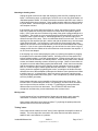
Invader MKII
User's Manual
Aiken Amplification, Inc.
1225 Montague Avenue
Greenwood, SC
Tel: 864-993-8383
http://www.aikenamps.com
Contents
Getting Started.....................................................................................................3
Front Panel Controls and Switches...................................................................5
Rear Panel Controls and Switches....................................................................8
Tube layout and replacement...........................................................................10
Biasing................................................................................................................12
Speakers.............................................................................................................13
Troubleshooting................................................................................................14
Specifications....................................................................................................17
Getting Started
Congratulations on purchasing your new
Aiken Invader MKII amplifier!
The Invader MKII is an all-tube amplifier,
available in 18 or 30 watt versions. This
amplifier is truly touch-sensitive, going from
clean to crunch to singing leads by just
adjusting the volume control on the guitar.
to provide a wide range of tones from any
guitar, using single-coil or humbucking
pickups.
The amplifier was designed specifically to
capture those old plexi/ali/bassman tones at
less than ear-shattering volumes, with the
addition of a 2-knob reverb and built-in
power attenuator.
The design features two internally-jumpered
channels, which are independently voiced,
Features include:
All-tube signal path. Preamp tubes are JJ/Tesla ECC83s and/or Ei 12AX7, reverb driver
is a JJ/Tesla ECC81/12AT7. Output tubes are JJ/Tesla EL84 (18W) or Svetlana EL34
(30W). Rectifier uses massive 3 amp 1000V ultra-fast recovery diodes (FREDs) for the
utmost reliability and a tight, fat low end.
Front panel controls/connections: Input jack, Volume 1 (bright), Volume 2 (dark), Bass,
Mid, Treble, Presence, Dwell, Reverb, Attenuator, and Variable. Input channels are
internally jumpered to allow a mix of the two volume controls to provide a wide range of
tones, allowing the amplifier to work well with any guitar, either single-coil or humbucker.
Exclusive Plexi/Ali front panel switch to reconfigure the preamp section to early "plexi"
style for a full rich tone (great for warm clean tones) or the later aluminum, or "ali" style
preamp, which is voiced brighter and tighter in the low end (best for distortion styles).
Rear panel controls/connections: AC mains input, interntional voltage selector allowing
operation at 100V/120V/200V/220V/230V/240V 50/60Hz, impedance selector switch for
4, 8, or 16 ohm operation, two 1/4" speaker jacks, and reverb footswitch jack. Also
includes locking mil-style RV6L bias pot and three tip jacks for easy bias setting without
having to remove the chassis from the cabinet.
Solid, finger-jointed birch-ply cabinet. The 1x12 combo is 25 1/2" wide, 21" tall, and 10
1/4" deep. The 2x12 combo is 29" wide, 21" tall, and 10 1/4" deep. The head is 25 1/2"
wide, 10 1/4" tall, and 9" deep.
Solid 16-gauge steel chassis, zinc-plated, yellow chromate conversion coated for
durability, corrosion-resistance and appearance. Front and rear faceplates are gold
anodized aluminum for durability and a classic appearance.
All hand-wired, “military style” turret-board construction (no PC boards), using chassismounted tube sockets for ease of maintenance and reliability. Built to last.
Premium, tight-tolerance parts are used for reliability, including 2W 1% carbon film and
metal film resistors, 5W metal oxide power resistors, 630V axial-leaded polypropylene
film/foil capacitors, and low-noise, sealed, 2W mil-style RV4 pots.
InvaderMKIIManual.doc
12/08/11
Copyright 2003-2011, Aiken Amplification, Inc.
Page 3 of 17
Massive, custom-wound, high-interleave transformers, rated for over twice the maximum
amplifier output power, allowing the amplifier to be run full power into an attenuator
continuously, without failures.
Output power (at onset of clipping): 18W (2-EL84 model) or 30W (2-EL34 model) into 4,
8, or 16 ohms resistive load.
Built-in power attenuator with 0dB, -3dB, -6dB, -9dB, -12dB positions, as well as a VAR
position that enables a second continuously-variable control that goes from –15dB down
to “bedroom” levels for low volume recording, or apartment/bedroom volume practicing.
Perfect for studio or club use. This is actually a true attenuator, working between the
output transformer and speakers, functionally similar to some of the current attenuators
on the market, but a completely unique design that doesn’t lose highs or lows as you
attenuate the signal.
Reverb: 2-knob spring reverb with dwell and level controls. Footswitch jack for on/off
control - accepts any standard grounding-type footswitch (not included).
Available in combo format with two 12" speakers, a single 12" speaker, or in a head
configuration. Celestion Greenback speakers are standard, others available upon
request for an additional charge. Extension speaker cabinets are also available.
InvaderMKIIManual.doc
12/08/11
Copyright 2003-2011, Aiken Amplification, Inc.
Page 4 of 17
Front Panel Controls and Switches
Input jack:
Plug your guitar in here and you are ready to rock!
Plexi/Ali switch:
This switch configures the preamp section to match either the warmer early
"plexi/Bassman" style preamp circuits or the later and brighter "aluminum panel" circuits.
For full-volume output stage distortion/crunch tones, the plexi/ali switch is usually best put
in the "ali" position, as this cuts some of the low end and adds a bit more gain and
midrange boost on the second stage. Too much low end can sound "boomy" or "mushy"
when playing wide open. The plexi setting is warmer, with more low end, and excels for
clean tones or for fattening up bright single-coil pickup guitars, such as Telecasters.
Because the plexi/ali switch completely reconfigures the preamp circuitry, it can produce
an audible "pop" or "thump" when switching. It is recommended that the volume controls
be turned down before changing modes.
Volume 1:
Volume 1 is the "bright" channel volume control.
Volume 2:
Volume 2 is the "dark" channel volume control.
Treble:
The treble control adjusts the high frequency equalization.
Middle:
The middle control adjusts the midrange frequency equalization.
Bass:
The bass control adjusts the low frequency equalization.
InvaderMKIIManual.doc
12/08/11
Copyright 2003-2011, Aiken Amplification, Inc.
Page 5 of 17
Dwell:
The dwell control adjusts the drive to the reverb tank. Higher dwell levels result in an
apparently "longer" decay time of the reverb. The dwell control also allows adjustment of
the proper drive level when playing clean or distorted. Distorted settings typically require
a much lower dwell level than clean settings, as there is more drive to the reverb tank
when the volume control is increased. A good "rule of thumb" is to back off on the dwell
as the volume is turned up, unless you want a very deep "surf" reverb.
Reverb:
The reverb control adjusts the amount of reverb added to the main signal. The reverb
circuit is a parallel mix circuit, so the dry path is not affected by the signal, and the reverb
is completely out of the circuit when the control is turned fully off.
Presence:
The presence control adjusts the high frequency equalization in the output stage. It is a
"shelving" control that operates by cutting the amount of high frequencies in the global
negative feedback loop, which results in a boost in the output high frequency range and a
subjectively "brighter" and more "open" tone in the highs due to the lower negative
feedback at those frequencies. Note that a small amount of noise during rotation of the
presence control is normal, and is due to a small DC voltage present on the control. This
was deliberately done, in keeping with the "old-style" presence control circuitry.
Attenuator:
The attenuator controls the overall output level, and allows turning the amplifier up to get
full-volume overdrive tones at lower volumes, without sacrificing tone quality. This
approach avoids the "buzzy" sound characteristic of master volume amplifiers. The
attenuator features 0dB, -3dB, -6dB, -9dB, and -12dB positions, as well as a VAR
position which enables a second, continuously-variable control that goes from –15dB
down to “bedroom” levels for low volume recording or bedroom/apartment practicing. It
is okay to switch the attenuator to different settings with the amplifier on, but it is
recommended to not be playing while changing positions, because a rotary switch, such
as that used in the attenuator, will have a small fractional amount of time where there is
no connection at all during the switching process. While we have never seen an output
transformer or tube damaged by this, it is remotely possible that the transient may cause
a problem, so it is not recommended. Before changing positions, just stop playing for a
second, change to the different attenuation level, and continue playing.
Variable:
This control is only enabled when the attenuator is set to the “VAR” position. It allows
adjustment from –15dB down to very low “bedroom” levels to allow quiet practicing or
recording.
Pilot lamp:
The pilot lamp lights when power is applied to the amplifier and the power switch is on.
The pilot lamp features a screw-on “jewel” that can be removed from the front panel to
replace the bulb without having to remove the chassis. The bulb is a standard #47
“bayonet” style bulb, available at most electronics supply stores.
InvaderMKIIManual.doc
12/08/11
Copyright 2003-2011, Aiken Amplification, Inc.
Page 6 of 17
Power switch:
The Power switch turns the amplifier on in the up position and off in the down position.
Glory switch:
What good is power without the glory? The Glory switch allows muting of the amplifier
output when not in use. When the switch is in the up position, the amplifier is on, and
when it is in the down position, the amplifier is on standby. The tube filaments remain on
and warmed up, so the amplifier is ready to play as soon as it is taken off standby. The
correct powerup sequence is to turn the amplifier on with the power switch and then, after
it has had time to warm up, the Glory switch is turned on. When turning the amplifier off,
the Glory switch should first be turned off, then the power is turned off after a few
seconds.
InvaderMKIIManual.doc
12/08/11
Copyright 2003-2011, Aiken Amplification, Inc.
Page 7 of 17
Rear Panel Controls and Switches
AC Mains:
Plug the supplied IEC mains cord into this outlet to provide power to the amplifier.
Mains Fuse:
18W amplifiers:
operation.
2A slo-blo for 100V/120V operation, 1A slo-blo for 200V-240V
30W amplifiers: 3A slo-blo for 100V/120V operation, 1½ A slo-blo for 200V-240V
operation.
AC Mains voltage selector:
Set this switch to the appropriate position to match the mains voltage in the country in
which you are using the amplifier. WARNING: Do not adjust this control with the AC
mains cord plugged in and the power on!!! Damage to the amplifier will result if the
switch is set to the wrong position. If you have any doubts as to which is the correct
voltage for the country you are in, call the factory or inquire with someone locally who will
know the correct mains voltage.
HT Fuse:
500mA fast-acting fuse
Impedance Selector:
The impedance selector allows selection of 4, 8, or 16 ohm output impedance to match
the speaker in use. Be sure to set this switch to the appropriate setting for the speaker or
speakers connected to the amplifier. All amplifiers are shipped from the factory with a
single 16-ohm speaker or a pair of speakers wired in series to provide a 16-ohm load.
This allows connection of an external 16 ohm cabinet to be used simultaneously with the
internal speaker by setting the impedance selector to 8 ohms, or four 16-ohm cabinets
can be used by setting the impedance selector to 4 ohms.
Speaker Jacks:
Two speaker jacks are provided to allow use of the amplifier with either the internal
speaker (combo units only) or up to two external speaker cabinets. More than two
external cabinets may be safely used with the amplifier, but this will require the use of "Y"
cables for the extra two cabinet connections. Be sure to use only quality speaker cable do NOT, under any circumstance, use guitar cable to connect the amplifier to a speaker
cabinet. Doing so may cause damage to the amplifier.
InvaderMKIIManual.doc
12/08/11
Copyright 2003-2011, Aiken Amplification, Inc.
Page 8 of 17
Footswitch:
This jack allows connection of any standard footswitch to remotely turn on the reverb on
and off.
Bias Test Jacks:
Three standard tip jacks are available to allow easy bias current measurements without
removing the chassis. Refer to the section on biasing for instructions on the use of these
jacks.
Bias:
A locking mil-style RV6 trimpot is provided to allow adjustment of bias current. The outer
locknut must be loosened before adjusting the screwdriver-slot control. Refer to the
section on biasing for further instructions.
InvaderMKIIManual.doc
12/08/11
Copyright 2003-2011, Aiken Amplification, Inc.
Page 9 of 17
Tube layout and replacement
The Invader uses four ECC83/12AX7 tubes, one ECC81/12AT7 tube, and two 6BQ5/EL84 output
tubes (or two EL34 tubes in the 30W version).
The preamp tubes are housed in removable "bayonet" metal shields. The shields can be
removed by pushing down on them and rotating the shield to the left, then pulling it upwards off
the tube. The tube can then be pulled out of the socket. The output tubes have spring wire
retainers that can be slipped off to one side, allowing easy removal of the EL84 tubes.
The preamp tube function is as follows, starting at the side closest to the input jack: preamp 1
(ECC83/12AX7), preamp 2/cathode follower (ECC83/12AX7), reverb driver (ECC81/12AT7),
reverb recovery (ECC83/12AX7), and phase inverter(ECC83/12AX7). The chassis top view
layout is shown in the diagram above.
You may freely sub any 12xxx type tube in the two preamp and phase inverter positions. It won't
hurt anything, and you may find some different tones you like. The 12AU7 is a good lower-gain
tube, as is the 5751. Other choices are 12AY7, 12AT7, or 12AZ7.
In addition, different
manufacturer's tubes will sound different. Some people prefer the tone of various Ei, Sovtek, or
other tubes, and some insist on NOS tubes for a true vintage tone. Feel free to experiment!
Note: vacuum tubes, especially output tubes, can get very hot in normal operation, and may
cause burns if removed before they have a chance to cool down. Be sure to wait several minutes
before replacing tubes to allow them to cool down. Do not, under any circumstances, remove or
replace the tubes with the power on, as this could cause a deadly electrical shock should the
glass break, exposing the high-voltage plate terminals. Also, be sure to pay attention to the
orientation of the tubes when putting them back in the socket. The tube pinout is keyed so it can
only be placed in the socket in one direction, and if the tube is forced in incorrectly, it can damage
the tube or the ceramic socket. The octal tubes in the 30W model have a phenolic key that fits a
corresponding keyhole in the socket. If this key is broken off, it will allow incorrect placement of
the tube in the socket, which could result in damage to the amplifier. Be sure to carefully
examine the tube before replacing it.
InvaderMKIIManual.doc
12/08/11
Copyright 2003-2011, Aiken Amplification, Inc.
Page 10 of 17
Output power reduction by using 6V6 tubes (30W models only):
It is possible to reduce the power of the 30W Invader to around 18W to 20W by changing the two
EL34 output tubes to 6V6 tubes. The amplifier will need to be rebiased before using, to insure
the tubes are running at a safe idle current . In order to familiarize yourself with the biasing
procedure, you should read the next section on biasing before making this change.
The proper procedure for changing from EL34 to 6V6 is as follows:
(1) Turn off the amplifier.
(2) Unscrew the locking nut on the rear panel bias potentiometer and turn the screwdriver bias
adjustment fully counter-clockwise (anti-clockwise for our friends across the pond).
(3) Remove the EL34 output tubes (Careful! They may be extremely hot if the amp has been
on!)
(4) Install the 6V6 output tubes
(5) Set the impedance selector to half the normal setting. For example, if you have a 16 ohm
cabinet connected, set the impedance selector to 8 ohms. If you have an 8 ohm cabinet, set
the impedance selector to 4 ohms. If you have a 4 ohm cabinet, set the impedance selector
to 4 ohms as well. If you are running two 16 ohm cabinets, set the impedance to 4 ohms. If
you are running two 8 ohm cabinets, set the impedance to 4 ohms as well. You cannot safely
run two 4 ohm cabinets.
Note: you can try setting the impedance selector to the normal
setting, i.e. matching the cabinet impedance. You may like the tone better that way, or not.
Either way, it won’t hurt anything.
(6) Turn on the power switch and wait a few minutes for the tubes to warm up.
(7) Bias the amplifier as indicated in the next section on biasing, but instead of setting the bias
adjustment to a max range of 60mV on the test jacks, set it no higher than 30mV, typically
around 25mV to 28mV for best tone.
(8) Tighten back down the bias adjust locking nut, and you’re ready to go.
To convert back to EL34 tubes:
(1) Turn off the amplifier.
(2) Unscrew the locking nut on the rear panel bias potentiometer and turn the screwdriver bias
adjustment fully counter-clockwise (anti-clockwise for our friends across the pond).
(3) Remove the 6V6 output tubes (Careful! They may be extremely hot if the amp has been on!)
(4) Install the EL34 output tubes
(5) Set the impedance selector to match the impedance of the cabinet you are using. For
example, if you have a 16 ohm cabinet connected, set the impedance selector to 16 ohms. If
you have an 8 ohm cabinet, set the impedance selector to 8 ohms. If you have a 4 ohm
cabinet, set the impedance selector to 4 ohms. If you are running two 16 ohm cabinets, set
the impedance to 8 ohms. If you are running two 8 ohm cabinets, set the impedance to 4
ohms. You cannot safely run two 4 ohm cabinets.
(6) Turn on the power switch and wait a few minutes for the tubes to warm up.
(7) Bias the amplifier as indicated in the next section on biasing, to a maximum of 60mV, typically
around 45mV to 50mV for best tone.
(8) Tighten back down the bias adjust locking nut, and you’re ready to go.
Other tube types:
You can also use any of the following tube types in the 30W Invader: 6L6, 5881, KT66, 6550.
Bias them the same as you would for EL34 tubes, as described in the next section on biasing.
InvaderMKIIManual.doc
12/08/11
Copyright 2003-2011, Aiken Amplification, Inc.
Page 11 of 17
Biasing
Biasing is very easy, and doesn't require removing the chassis from the cabinet. You simply use
a voltmeter (any inexpensive digital multimeter will do), set it for the smallest DC voltage range
(typically 200mV). Then:
(1) Unplug any guitar cords going into the input jack. Turn the two volume controls all the way
down (other control positions don’t matter). Unscrew the lock nut on the bias pot on the rear
panel, and turn the bias control all the way down (counterclockwise). Turn the Power switch on,
wait a minute or so until the tubes have warmed up, then turn on the Glory switch. Wait a few
more minutes for the tubes to reach their stable operating point.
(2) Put the negative probe lead into the black tip jack (leaving the positive probe in one of the red
tip jacks - it doesn't matter which one), and adjust the bias pot for approximately 30mVDC (that's
30 millivolts, not 30V!).
Note: For the 2-EL34 30W amps, use the same procedure as above, but adjust the bias pot for
60mV, which corresponds to 60mA per side.
(3) Put the red meter probe leads into the other red tip jack and check for 30mVDC (or 60mVDC
for 30W amps). If the reading is higher than 30mVDC (or 60mVDC for 30W), adjust the bias pot
down until the meter reads 30mVDC (or 60mVDC for 30W). If it is lower than 30mVDC (or
60mVDC for 30W), leave it set where it was. Note: if the two readings differ by more than 5mV
to 10mV, this indicates that the two tubes are too far out of match, and they probably should be
replaced with another set that are better balanced. However, it will not harm the amplifier to use
unbalanced tubes, as long as the bias pot is set for 30mV (or 60mV for the 30W) on the highest
current side. Check the voltage from the black tip jack to the left red tip jack and then to the right
red tip jack, and adjust the bias for 30mV (or 60mV for 30W amps) on the highest reading side.
An imbalance can sometimes even sound good! Too high an imbalance, however, can cause
high levels of hum in the output and loss of low end response.
(4) Once the bias is set, tighten down the lock nuts on the bias trimpot and you're ready to play.
Note: the 30mV setting (60mV for the 30W amp) should be considered a maximum setting. It is
perfectly acceptable to bias at a lower setting. This will result in longer tube life, lower
background noise, and a cleaner tone, although if you go too low the increased crossover
distortion may become objectionable. You may prefer the tone with the tubes biased colder, so
feel free to experiment, it won’t hurt anything as long as you don’t bias the tubes too much hotter
than the recommended setting.
Note: It is normal for tubes to drift a bit, particularly when new, until they have had several hours
of playing time on them. The bias will also vary a bit with variations in AC line voltage (a Variac is
used to set the AC line voltage to 120V at the factory before biasing the tubes). Small variations
like this shouldn't cause any problems, so don't worry about constantly checking the bias and
driving yourself crazy trying to keep it at exactly 30mV. If a tube is biased too hot, the plate will
glow a dull red color. The plate is the large grey metal "box" structure seen inside the tube.
Don't confuse normal filament glow with plate glow. Plate glow can usually be seen as a "hot
spot" near the center of the plate, sometimes accompanied by a "hot" smell and some "ticking"
noises as the metal expands. Continued operation with glowing plates will soon result in failure of
the tubes, possibly damaging screen grid resistors or other amplifier components. The HT fuse
should prevent any major damage to output or power transformers, or other expensive
components.
InvaderMKIIManual.doc
12/08/11
Copyright 2003-2011, Aiken Amplification, Inc.
Page 12 of 17
Speakers
Changing speakers is like getting a whole new amp. Every model sounds completely different,
some sounding quite good and some amazingly bad. The amplifier is particularly suited for use
with Celestion loudspeakers, which give the characteristic "British" sound this amplifier is
designed to create.
Celestion Greenbacks have less volume and a dip in the mids, which makes them nice and
smooth. They are rated at 25W, so they make a nice match for the Invader 18, but are a bit
under-rated for the Invader 30 in a 1x12 configuration. Celestion Alnico Blues are by far the
loudest, with a nice chimey top end (but not extremely cutting highs) and full bottom end, but their
rather pronounced midrange and very low power rating (18W) may make them undesirable for
some users. If you do use this speaker, you may want to set the attenuator to the -3dB position
when playing fully distorted. Jensen P12B "bell" alnico's are far brighter than the Celestion Alnico
Blue, but don't have as good a low-end response. They are, however, rated at 50W and sound
very nice when paired with the Alnico Blue in a 2x12 configuration. Celestion Vintage 30's have a
very pronounced midrange, which may be a bit too harsh in an open-back configuration, which
naturally enhances the midrange frequencies, and can sound a bit "boxy" with the wrong speaker.
They do sound good for some blues styles, and can easily handle the power of the Invader 18 or
30 in a 1x12 configuration. Celestion G12H30's are like a cross between the Greenback and the
Vintage 30, with more low end than the Vintage 30 and not quite as pronounced a midrange, so
they tend to sound subjectively "better" in an open-back cabinet. The G12H30 is preferred in a
1x12 configuration by many customers, as is the Greenback. Your mileage may vary.
Closed-back cabinets have better and tighter bass, without the pronounced midrange hump of the
open-backs, but they don't disperse on stage as well, and tend to be "beamy", sounding very loud
out front, but if you stand above and to the front or back, you can't hear yourself as well. Still,
there is nothing quite like the tone of a cranked up 4x12 cabinet loaded with Greenbacks! For a
more portable closed back, a 2x12 loaded with either of those Celestions will do the trick nicely.
Putting a 2x12 on each side of the stage fills up the tone very well, and provides an almost
stereo-like sound field because of the cancellations that occur when standing in different places
on stage. The Greenbacks are the recommended speaker for 2x12 and 4x12 cabinets for the
“classic vintage” tone.
When changing speakers, always insure that the output impedance selector is set to match the
impedance of the speakers connected to the output jacks. The Invader has two paralleled output
jacks, and can easily drive two 4x12 cabinets to extremely loud volume levels, despite the 18W
rating.
InvaderMKIIManual.doc
12/08/11
Copyright 2003-2011, Aiken Amplification, Inc.
Page 13 of 17
Troubleshooting
Pilot lamp not lit:
Is the amplifier plugged into a functional outlet of the appropriate voltage?
Is the mains fuse blown? If so, replace with the appropriately rated fuse. If the fuse
again blows, the amplifier may have a shorted output tube or rectifier tube. Replace the
tubes and fuse, and power the amplifier up again. If the fuse still blows, the amplifier will
need to be serviced.
Pilot lamp lit, but no sound:
Is the HT fuse blown? If so, replace with the appropriately rated fuse. If the fuse again
blows, the amplifier may have a shorted preamp tube, output tube or rectifier tube.
Replace the tubes and fuse, and power the amplifier up again. If the fuse still blows, the
amplifier will need to be serviced.
Is the speaker functional and plugged in correctly? Insure the amplifier's output
impedance selector is correctly set to match the speaker in use.
Is the guitar cord functional? Bypass any pedals and plug straight in with a known good
cable to test.
No reverb:
Are the reverb cables plugged into the tank (inside the bag at the bottom of combo
cabinets) and into the RCA jacks on the amplifier chassis?
If the amp or tank has been removed from the cabinet, the cables may have accidentally
been switched. Try reversing the leads that plug into the chassis jacks (the reverb tank
"IN" cable should go to the jack nearest the small reverb driver transformer, and the
reverb tank "OUT" should go to the other jack).
With the amplifier on, turn the reverb control mid way up and shake the tank - if the tank
makes a "crashing" noise through the speaker, the recovery side of the reverb circuit is
functional, and the problem is in the send side. If there is no noise, the problem is on the
recovery side. If it is on the recovery side, remove the tank from it's tolex isolation bag
and repeat the test to insure the reverb springs aren't inadvertently touching the bag.
If the problem is on the recovery side, try replacing the ECC83/12AX7 reverb recovery
tube. If the problem is on the send side, try replacing the ECC81/12AT7 reverb driver
tube. See the tube replacement section for locations of these two tubes.
Try replacing the cable on the bad side. If this doesn't fix the problem, try replacing the
reverb tank. If the problem still exists, the amplifier will need to be serviced.
InvaderMKIIManual.doc
12/08/11
Copyright 2003-2011, Aiken Amplification, Inc.
Page 14 of 17
Humming or buzzing noise:
Unplug the guitar cord from the input and unplug any cable used for jumpering the two
inputs. If the buzzing stops, try replacing the cord. Be sure to use only guitar cables, not
unshielded speaker cables! If in doubt, unscrew the connector and look to see if there is
a shield around the center connector. Some smaller speaker cables are easily mistaken
for guitar cables. Fluorescent lights and light dimmers can be a source of hum/buzz, as
can computer monitors.
If the buzzing only occurs when using effects or a tuner, the problem is likely a ground
loop hum (in particular, the Korg rack mount tuner seems to be susceptible to ground
loops). If this is the case, the hum/buzz will go away if the guitar is plugged straight in to
the amplifier. The solution is to use a ground loop hum eliminator (there are a few on the
market) or make a guitar cord with a "telescoping shield" to go from the output of the
effects to the input of the amp. This is a cord with the shield cut on one end. The cut end
should go into the amplifier input jack, and the end with the shield must go into the output
of the effects unit/tuner. In a emergency, a ground lift plug (three-prong to two-prong
adapter) can be used on the tuner/effects box, but this is not recommended due to safety
concerns. If you do use a ground lift adapter, you should check to see if there is any AC
voltage present from the chassis of the rack effect/tuner to the chassis of the amplifier. If
so, do not use the adapter!
If the buzzing only occurs when playing the guitar, try replacing the speaker or plugging
the amplifier into an extension speaker cabinet. A buzzing noise from the speaker can
indicate a blown speaker, or one with a warped frame. Buzzing noises that occur only on
certain notes can be indicative of a cabinet problem. Check all rear panel screws, handle
screws, and chassis mounting screws to insure they are tight. Check to insure there are
no speaker or reverb cables rattling against the baffle board. Check the two screws that
hold the nameplate to the front of the amplifier, as the nameplate can cause a rattle or
buzz if it is loose enough to vibrate against the front panel board. If the nameplate
buzzing cannot be stopped by tightening the screws, a small piece of double-stick tape
affixed to the rear of the nameplate will dampen the vibration. Some speakers are known
to exhibit "cone cry", or "ghost noting", which is a second, out-of-tune note that occurs
only when playing certain notes on the guitar. If this is suspected, try another speaker to
see if the problem goes away.
Some preamp tubes are more susceptible to filament-induced hum than others. The
ECC83/12AX7 is a dual triode (two tubes in one package), and some tubes will exhibit
hum in only one of the two sections, or in both. Try replacing the preamp tubes with
different ones to see if the hum decreases. The JJ/Tesla ECC83S is the least
microphonic and least noisy current-manufacture tube we have found.
Hissing noise:
A small amount of hiss is a characteristic of higher-gain tube amps, and is generally
unavoidable. Excessive levels of hiss are usually caused by bad preamp tubes.
Some preamp tubes have more hiss than others. Try replacing the preamp tubes with
different ones to see if the hiss decreases.
"Ticking" noise:
Some tubes tend to exhibit a low-level "ticking" noise right after the amplifier is taken off
standby. The noise stops after a second or two, when the tube has had a chance to
stabilize, and is not indicative of a problem.
InvaderMKIIManual.doc
12/08/11
Copyright 2003-2011, Aiken Amplification, Inc.
Page 15 of 17
Ringing noise or feedback that occurs with no guitar plugged in:
If the amplifier exhibits a "ringing" noise, especially when tapping on the chassis, or if it
makes a howling or whistling feedback noise when the volume is turned up but no guitar
is plugged in, there is probably a microphonic tube in the amplifier, likely in the first
position (the small tube closest to the input jacks), or in the reverb recovery position.
Remove the shield and lightly tap on the tube with the volume turned up. A small amount
of noise is normal, but a loud, ringing noise indicates a microphonic tube, which should
be replaced. In a emergency, you can swap the other ECC83/12AX7 preamp tubes
around until you find the least microphonic one to put in the first position. Typically, the
phase inverter tube is the least susceptible to microphonics, so the most microphonic
tube should be used in this position. The least microphonic tube should be used in the
first position, and the next least microphonic tube should be used in the reverb recovery
position. When purchasing tubes, be sure to purchase tubes that have been tested for
microphonics. Many vendors do not test for microphonics, and you could end up wasting
your money on tubes that are unsuitable for use. Combo amps are more susceptible to
microphonics than heads, because the sound field coming from the back of the speaker
can excite the tube into oscillation. In rare cases, the EL84 or EL34 output tubes can be
microphonic, particularly if they are at the end of their lifespan.
InvaderMKIIManual.doc
12/08/11
Copyright 2003-2011, Aiken Amplification, Inc.
Page 16 of 17
Specifications
Output Power:
18W for the 2-EL84 model or 30W for the 2EL34 model, at onset of clipping into resistive
load at rated impedance.
Input Impedance:
1Megohm
Input sensitivity:
10mV for output clipping, all volume/tone
controls fully up, ali mode.
Tube complement:
Four ECC83/12AX7, one 12AT7, two EL84
(18W model), or two EL34 (30W model).
Fuses:
18W/100V-120V: Mains: 2A slo-blo, HT:
500mA fast-acting
18W/200V-240V: Mains: 1A slo-blo, HT:
500mA fast-acting
30W/100V-120V: Mains: 2A slo-blo, HT:
500mA fast-acting
30W/200V-240V: Mains: 1A slo-blo, HT:
500mA fast-acting
Speakers:
Varies, depending on model and customer
preference.
Footswitch:
Accepts any normally-open on/off footswitch
to control reverb function (not included)
Dimensions:
Head: 25.5" W x 10.25" H x 9" D
Weight:
1x12 combo:
25.5" W x 21"H x 10.25" D
2x12 combo:
29" W x 21" H x 10.25" D
18W chassis only: 23 lbs
30W chassis only: 29 lbs
Head cabinet (no chassis): 14lbs
1x12 combo cabinet with Greenback speaker
(no chassis): 33bs
2x12 combo cabinet with Greenback
speakers (no chassis): 46lbs
Examples:
18W head total weight = 37lbs
30W head total weight = 43lbs
18W 1x12 combo total weight = 56lbs
18W 2x12 combo total weight = 69lbs
30W 2x12 combo total weight = 75lbs
InvaderMKIIManual.doc
12/08/11
Copyright 2003-2011, Aiken Amplification, Inc.
Page 17 of 17