1
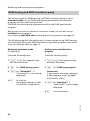
Operating instructions
for system users
Heating system with
weather-compensated digital boiler and heating circuit control
VITOTRONIC 200
VITOTRONIC 300
Vitotronic 200, type KW2
Vitotronic 300, type KW3
5592Ă363ĂGBăăă7/2002
Please keep safe
Introductory information
For your safety
Please follow these safety instructions closely to prevent accidents and
material losses.
If you smell gas
H Do not smoke! Do not use naked
flames or cause sparks (e.g. by
switching lights or electrical
appliances on and off).
H Open windows and doors.
H Close the gas shut-off valve.
H Notify your heating engineer/
installation contractor from outside
the building.
H Observe the safety regulations of
your gas supplier (see gas meter)
and of your heating engineer (see
commissioning/training report).
In an emergency
H Immediately isolate the mains
electrical supply, e.g. by removing
a separate mains fuse or by means
of a mains electrical isolator
(unless you smell gas).
H Close the shut-off valves of the
main fuel lines.
H In case of fire, use an appropriate
fire extinguisher.
Work on the equipment
Installation, initial start-up, inspection,
maintenance and repairs must only
be carried out by a competent person
(heating engineer/installation
contractor).
Before working on the equipment/
heating system, isolate the mains
electrical supply (e.g. by removing a
separate mains fuse or by means of a
mains electrical isolator) and safeguard
against unauthorised reconnection.
When using gas as fuel, also close
the shut-off valve and safeguard
against unauthorised re-opening.
Installation of additional components
The installation of additional components which have not been tested
together with the boiler can adversely
affect the boiler function.
Our warranty does not cover and we
accept no liability for damage caused
by the installation of such components.
Boiler room conditions
H Do not permit air pollution by
halogenated hydrocarbons (e.āg. as
contained in aerosols, paints,
solvents and cleaning agents).
H Do not use rooms with high levels
of dust.
H Do not use rooms with permanently
high levels of humidity.
H The room should be frost protected
H Max. ambient temperature 35ĂºC.
H Ensure good ventilation and do not
close or obstruct any vents (where
provided).
The user of any combustion equipment must notify the local chimney sweep
within four weeks of completion (in Germany).
2
5592Ă363ĂGB
Notice of completion
Contents
Index
Introductory information
For your safetyĂ . . . . . . . . . . . . . . . . . . . . . . . . . . . . . . . . . . . . . . . . . . . . . . . . . . . . . . . . . . . . . . . . . . . . . . . . . . . . . . . . . . . . . . . . . . . . . . . . . . . . . . . . . . . . . . . . . . . . . . . . . .
Notice of completionĂ . . . . . . . . . . . . . . . . . . . . . . . . . . . . . . . . . . . . . . . . . . . . . . . . . . . . . . . . . . . . . . . . . . . . . . . . . . . . . . . . . . . . . . . . . . . . . . . . . . . . . . . . . . . . .
2
2
Quick start
Where to find the controlsĂ . . . . . . . . . . . . . . . . . . . . . . . . . . . . . . . . . . . . . . . . . . . . . . . . . . . . . . . . . . . . . . . . . . . . . . . . . . . . . . . . . . . . . . . . . . . . . . . . . . 4
Your heating system is pre-set at the factoryĂ . . . . . . . . . . . . . . . . . . . . . . . . . . . . . . . . . . . . . . . . . . . . . . . . . . . . . . . . . . . . . 5
Summary of controls and indicatorsĂ . . . . . . . . . . . . . . . . . . . . . . . . . . . . . . . . . . . . . . . . . . . . . . . . . . . . . . . . . . . . . . . . . . . . . . . . . . . . . . 6
Heating circuit selection ć before adjustments and scanningĂ . . . . . . . . . . . . . . . . . . . . . . . . . . . . . 9
Selecting the heating program (summer, winter)Ă . . . . . . . . . . . . . . . . . . . . . . . . . . . . . . . . . . . . . . . . . . . . . . . . . . . . 10
Changing the room temperature (day and night temperature)Ă . . . . . . . . . . . . . . . . . . . . . . . . . . 11
Scanning temperatures and operating conditionsĂ . . . . . . . . . . . . . . . . . . . . . . . . . . . . . . . . . . . . . . . . . . . . . . . . . . . 12
Utilising the Comfort function
Setting up the party modeĂ . . . . . . . . . . . . . . . . . . . . . . . . . . . . . . . . . . . . . . . . . . . . . . . . . . . . . . . . . . . . . . . . . . . . . . . . . . . . . . . . . . . . . . . . . . . . . . . . . . 13
Activating economy modeĂ . . . . . . . . . . . . . . . . . . . . . . . . . . . . . . . . . . . . . . . . . . . . . . . . . . . . . . . . . . . . . . . . . . . . . . . . . . . . . . . . . . . . . . . . . . . . . . . . . . 14
Start-up/shutdown
Starting the heating systemĂ . . . . . . . . . . . . . . . . . . . . . . . . . . . . . . . . . . . . . . . . . . . . . . . . . . . . . . . . . . . . . . . . . . . . . . . . . . . . . . . . . . . . . . . . . . . . . . . 15
Shutting down the heating systemĂ . . . . . . . . . . . . . . . . . . . . . . . . . . . . . . . . . . . . . . . . . . . . . . . . . . . . . . . . . . . . . . . . . . . . . . . . . . . . . . . . . 16
Modifying and scanning time programs
General notesĂ . . . . . . . . . . . . . . . . . . . . . . . . . . . . . . . . . . . . . . . . . . . . . . . . . . . . . . . . . . . . . . . . . . . . . . . . . . . . . . . . . . . . . . . . . . . . . . . . . . . . . . . . . . . . . . . . . . . . . . . . . . . . . 17
Central heatingĂ . . . . . . . . . . . . . . . . . . . . . . . . . . . . . . . . . . . . . . . . . . . . . . . . . . . . . . . . . . . . . . . . . . . . . . . . . . . . . . . . . . . . . . . . . . . . . . . . . . . . . . . . . . . . . . . . . . . . . . . . . 18
DHW heating and DHW circulation pump . . . . . . . . . . . . . . . . . . . . . . . . . . . . . . . . . . . . . . . . . . . . . . . . . . . . . . . . . . . . . . . . . . . . . 20
Settings
Changing the DHW temperatureĂ . . . . . . . . . . . . . . . . . . . . . . . . . . . . . . . . . . . . . . . . . . . . . . . . . . . . . . . . . . . . . . . . . . . . . . . . . . . . . . . . . . . . . .
Adjusting the economy mode for holiday periods . . . . . . . . . . . . . . . . . . . . . . . . . . . . . . . . . . . . . . . . . . . . . . . . . . . .
Changing date and timeĂ . . . . . . . . . . . . . . . . . . . . . . . . . . . . . . . . . . . . . . . . . . . . . . . . . . . . . . . . . . . . . . . . . . . . . . . . . . . . . . . . . . . . . . . . . . . . . . . . . . . . . . .
Selecting the required languageĂ . . . . . . . . . . . . . . . . . . . . . . . . . . . . . . . . . . . . . . . . . . . . . . . . . . . . . . . . . . . . . . . . . . . . . . . . . . . . . . . . . . . . . .
Modifying the boiler heating characteristicsĂ . . . . . . . . . . . . . . . . . . . . . . . . . . . . . . . . . . . . . . . . . . . . . . . . . . . . . . . . . . . . . .
23
24
26
27
28
What to do if ...
Special displaysĂ . . . . . . . . . . . . . . . . . . . . . . . . . . . . . . . . . . . . . . . . . . . . . . . . . . . . . . . . . . . . . . . . . . . . . . . . . . . . . . . . . . . . . . . . . . . . . . . . . . . . . . . . . . . . . . . . . . . . . . . 31
Diagnosis and troubleshootingĂ . . . . . . . . . . . . . . . . . . . . . . . . . . . . . . . . . . . . . . . . . . . . . . . . . . . . . . . . . . . . . . . . . . . . . . . . . . . . . . . . . . . . . . . . . 32
5592Ă363ĂGB
RepairsĂ . . . . . . . . . . . . . . . . . . . . . . . . . . . . . . . . . . . . . . . . . . . . . . . . . . . . . . . . . . . . . . . . . . . . . . . . . . . . . . . . . . . . . . . . . . . . . . . . . . . . . . . . . . . . . . . . . . . . . . . . . . . . . . . . . . . . . . . . . 37
Energy saving tipsĂ . . . . . . . . . . . . . . . . . . . . . . . . . . . . . . . . . . . . . . . . . . . . . . . . . . . . . . . . . . . . . . . . . . . . . . . . . . . . . . . . . . . . . . . . . . . . . . . . . . . . . . . . . . . . . . . . . . 39
Key word indexĂ . . . . . . . . . . . . . . . . . . . . . . . . . . . . . . . . . . . . . . . . . . . . . . . . . . . . . . . . . . . . . . . . . . . . . . . . . . . . . . . . . . . . . . . . . . . . . . . . . . . . . . . . . . . . . . . . . . . . . . . . 40
3
Quick start
Where to find the controls
You can change all settings for your heating system centrally at the control
unit and its integral programming unit.
You may also make such changes on the remote control unit, if your system
is equipped accordingly.
Remote control operating instructions
Please observe particularly the chapter "Special displays" in these
instructions.
The control unit is located in a
"drawer".
To open, pull the programming unit
forward, flip it up and lock it in a
position where you can clearly read
the details in the display window.
A
B C
5592Ă363ĂGB
A Programming unit
B Programming unit flap
C Hinged cover
4
Quick start
Your heating system is pre-set at the factory
The control unit is preset at the factory for standard operation. Your heating
system is now ready to operate.
You may change the factory settings in accordance with personal
requirements.
Day of the week and time (CET)
These were set up in the factory. The
system automatically changes over
between summer and winter.
Heating program
This is set to "Heating and DHW",
i.e. central heating and DHW are
operated (if a DHW cylinder is
installed) in accordance with the
programmed times.
Time programs
Between the hours of 6.00 and
22.00Ăhrs, the central heating
operates with standard room
temperatures, and between 5.30 and
22.00 hrs DHW is produced (if a DHW
cylinder is installed).
5592Ă363ĂGB
Between 22.00 and 6.00Ăhrs, central
heating operates with a reduced
room temperature (set to frost
protection, 3 ºC).
5
Quick start
Summary of controls and indicators
Controls with open flap
Mains switch (page 15)
Fuses
Unblocking excess temperature
Control thermostat
Boiler temperature
Mo
.
5592Ă363ĂGB
Flap (page 4)
Test switch (only for service purposes)
Emissions test switch (page 33)
ON/OFF lamp (green) (page 15, 16)
Fault indicator (red) (page 32)
6
Quick start
Summary of controls and indicators (cont.)
Economy mode (page14)
Heating programs (pageĂ10)
Standard room temperature (page 11)
Party mode (page 13)
Basic setting (page 8)
Help (page 12, 27)
Confirmation/acknowledgement
Symbols (page 8)
Display window
Boiler temperature
Mo
Programming unit flap
(page 4)
Adjusting values
Holiday program (page 24)
DHW temperature (page 23)
Date/time (page 5, 26)
Heating curve level (page 28)
7
5592Ă363ĂGB
Heating curve slope
(page 28)
Reduced room temperature
(page 11)
Time program (pageĂ17)
Heating circuit selection
(page 9), for Vitotronic 200
only ! and ?
7
Quick start
Summary of controls and indicators (cont.)
Display window contrast settings
Open the programming unit flap and
press d, simultaneously set the
contrast using a or b.
Basic setting e
All modified values are returned to
their factory settings.
Flashing values
Details which flash in the display
indicate that modifications may be
made.
5592Ă363ĂGB
Display window symbols
(these symbols are not always
displayed, but appear subject to the
system version and operating
conditions)
e If frost is likely
s for central heating with
standard room temperature
m for central heating with
reduced room temperature
w DHW heating,
cylinder loading pump running
p Heating circuit pump running
V Mixer "Open"
v Mixer "Closed"
A Burner ON
Q Radio clock reception
8
Quick start
Heating circuit selection ć before adjustments and scanning
For heating systems with only one heating circuit, the heating circuit selection
key ! and one heating program key are illuminated and you may begin all
settings steps.
For heating systems with two or three heating circuits, select the respective
heating circuit before making any adjustments or before scanning the heating
circuit concerned.
Heating circuit selection key !: heating circuit 1 without mixer
Heating circuit selection key ?: heating circuit 2 with mixer
Heating circuit selection key §: heating circuit 3 with mixer (only
Vitotronic 300)
Your heating contractor will label each heating circuit individually.
Boiler temperature
Mo
! or ? or §; the following keys
will then illuminate:
H Heating circuit selection key
H current heating program
(see page 10).
H Party or economy mode, if set up
(see page 13 and 14).
If you have not selected the required
heating circuit before changing
settings, the display window will
show "First press key 1 or 2" or
"First press key 1, 2 or 3".
You can now begin setting up the
selected heating circuit.
5592Ă363ĂGB
Please note:
The key illumination will extinguish
after a short time if you make no
further changes.
9
Quick start
Selecting the heating program (summer, winter)
1. !, ? or §; the respective key
will then illuminate.
2. Select the heating program with
keys G, L or K.
Heating and DHW
Example: winter and transitional periods
H Central heating with alternate standard and reduced room
temperature (frost protection) acc. to programmed times
H DHW heating (if a DHW cylinder is installed) and DHW
circulation pump (if installed) ON acc. to set times
H Frost protection for boiler and DHW cylinder
Please note:
If this key is illuminated,
H symbol "s" appears, if central heating with standard room
temperature is active,
H symbol "m" appears, if central heating operates with a
reduced room temperature higher than 3ĂºC,
(see pageĂ11).
Only DHW
Example: Summer
H No central heating
H DHW heating (if a DHW cylinder is installed) and DHW
circulation pump (if installed) ON acc. to set times
H Frost protection for boiler and DHW cylinder
Standby mode
H No central heating
H No DHW heating
H Frost protection for boiler and DHW cylinder
5592Ă363ĂGB
Please note:
The circulation pumps are briefly started every 24Ăhours to
prevent them from seizing up.
10
Quick start
Room temperature
With the "Heating and DHW" program, the central heating operates
alternately with "Standard room temperature" and "Reduced room
temperature" acc. to set times (see page 17).
Change the standard room
temperature (day temperature)
Change the reduced room
temperature (night temperature)
Example:
For those times when you are at
home and wish to have a
comfortable ambience.
Example
For night and other times when you
are not in the living area.
Basic factory setting:
20ĂºC from 6.00 until 22.00Ăhrs.
"Standard room temperature" is
adjustable from 3Ăto 37ĂºC.
Basic factory setting:
Frost protection 3ĂºC
from 22.00 until 6.00Ăhrs.
"Reduced room temperature" is
adjustable from 4Ăto 37ĂºC.
1. !, ? or §; the respective key
will then illuminate.
Press the following keys:
2. Set the required temperature with
the rotary selectorĂĘts".
1. !, ? or §; the respective key
will then illuminate.
Standard room temp.
s
20
2. E
ºC
for "Reduced room temp.";
the current temperature will
flash.
Reduced room temp.
m
14
ºC
"Frost protection" appears
in the display, if
temperature 3 has been
selected.
5592Ă363ĂGB
3. a/b for the required
temperature.
4. d
as confirmation; the
temperature no longer
flashes and is now saved.
11
Quick start
Scanning temperatures and operating conditions
Subject to connected components and settings made, you can scan current
temperatures and operating conditions.
Press the following keys:
1. !, ? or §; the respective key
will then illuminate.
2. c
for "Outside temperature".
Outside temperature
i
9
ºC
3. a/āb for further scans.
4. c
to end scanning.
Heating program, scan party or
economy mode
Press heating circuit selection key;
the key of the active heating
program will illuminate (see
page 9).
5592Ă363ĂGB
H Holiday program with departure
and return date, if programmed.
H Outside temperature
H Boiler water temperature
H Flue gas temperature,
if a sensor is installed.
H Domestic hot water temperature
H Flow temperature,
for heating circuit with mixer.
H Return temperature,
for heating circuit with mixer,
subject to a sensor being installed.
H Room temperature,
if a Vitotrol remote control is
installed.
H Hours run of the burner
H Number of burner start-ups
H Fuel consumption subject to the
appropriate settings having been
made by the heating contractor.
H Time
H Date
H Burner On/Off
H Cylinder loading pump On/Off
H DHW circulation pump On/Off
H Heating circuit pump On/Off
H Mixer open/closed
for heating circuit with mixer
0 ¢ Close(d)
1 to 99 (%)
100 ¢ Open
H Language
12
Utilising the Comfort function
Setting up the party mode
If you wish to heat and provide DHW (subject to a DHW cylinder being
installed) in the short term and independent of the set heating and time
program.
Press the following keys:
1. !, ? or §; the respective key
will then illuminate.
2. M
for "Party mode"; the party
temperature flashes.
Heating DHW once outside the
programmed periods
H not in heating program "9", and
not during holiday program "j"
H The DHW temperature must be
below the set value (see page 23).
Press the following keys:
Party mode
20
ºC
1. !, ? or §; the respective key
will then illuminate.
3. If you want to change the party
temperature:
a/b for the required
temperature.
2. M
for "Party mode".
3. d
to confirm; DHW will be
heated up.
4. d
4. After approx. 10 seconds, press
button M again.
as confirmation; the
temperature no longer
flashes and is now saved.
End party mode
5592Ă363ĂGB
H The party mode ends with the next
automatic change to central
heating at "Standard room
temperature".
H If you want to prematurely
terminate party mode, press the
heating circuit selection key again
and M; the key illumination
extinguishes.
13
Utilising the Comfort function
Activating economy mode
If you want to heat briefly in economy mode whilst the heating mode is set to
operate at standard room temperature.
In economy mode, the set room temperature will be reduced automatically.
Economy mode is only possible in heating programĂ"rw" (see page 10).
Activating economy mode
Press the following keys:
1. !, ? or §; the respective key
will then illuminate.
2. N for "Economy mode".
Economy mode
Terminating economy mode
5592Ă363ĂGB
H The economy mode ends
automatically when the central
heating is next changed to
"Reduced room temperature".
H If you want to prematurely
terminate economy mode, press
the heating circuit selection key
again and N; the key illumination
extinguishes.
14
Start-up/shutdown
Starting the heating system
The initial start-up and matching of the control unit to local conditions and
the structural characteristics of the building must be carried out by your
heating contractor.
A
1. Check the pressure of your
heating system on the pressure
gauge A:
If the needle is below the red
marker, the system pressure is too
low ć in which case, top up with
water or contact your heating
engineer.
2. Open the shut-off valves in the oil
supply pipes (at the oil tank and
filter) or open the gas shut-off
valve.
3. Switch on the mains supply, e.g.
at a separate fuse or a mains
isolator.
5592Ă363ĂGB
4. Switch on the main ON/OFF
switchĂ"8"; standby mode is then
indicated by the green lamp (ON
lamp); shortly after the display will
indicate the boiler temperature
(see page 6).
Your heating system and, if
installed, your remote control unit
are now ready to operate.
15
Start-up/shutdown
Shutting down the heating system
If you intend shutting down your heating system for a certain time, e.āāg.
during a summer holiday, change to Standby mode (see "Selecting heating
program" on pageĂ10).
Shut down your heating system completely, if it will not be needed for longer
periods of time (several months).
Before you shut down your heating system for longer periods it would be
advisable to contact your local heating contractor.
Where necessary, your contractor can take certain measures, e.āāg. protecting
the system against frost or preserving the heating surfaces.
1. Switch off the main ON/OFF
switch "8" .
The green light (ON lamp)
extinguishes.
2. Close the shut-off valves in the oil
supply pipes (at the oil tank and
filter) or the gas shut-off valve,
whichever applies.
3. Isolate the system from the mains
electricity supply, e.g. by
removing a separate fuse or by
means of a mains electrical
isolator.
As the system is now voltage free,
the heating system has no frost
protection.
5592Ă363ĂGB
Please note:
All settings remain intact.
16
Modifying and scanning time programs
General notes
You can set time programs for central heating, for DHW heating (subject to a
DHW cylinder being installed) and the DHW circulation pump (if installed).
The DHW circulation pump ensures that hot water is available at the draw-off
points at short notice.
The time program comprises four time phases, i.e.
H for central heating, up to four changes between "Standard room
temperature" and "Reduced room temperature" can be programmed.
H DHW heating and DHW circulation pump can be activated/deactivated up to
four times per day.
At the factory, phase 1 is set for all weekdays, i.e. in this phase all rooms are
heated at standard room temperature, DHW is produced and the DHW
circulation pump is activated.
The following keys are allocated to the time programs:
Key
Time program for
Basic factory setting
A
Central heating
Standard room temperature:
from 6.00 to 22.00 hrs
B
DHW heating
On:
5.30 to 22.00 hrs
C
DHW circulation pump
On:
5.30 to 22.00 hrs
You can select identical time programs for all weekdays or individual ones for
each weekday.
5592Ă363ĂGB
Take the response time of your heating system into consideration when
setting the time programs. Select correspondingly earlier start-up and
shutdown times.
17
Modifying and scanning time programs
Central heating
Press the following keys:
2. A
for "Central heating time
program".
Please note:
If you want to terminate the time
program early, press A again
and confirm with d.
3. a/b to
"1ć7" will be displayed, if
you want to set up the
same time phases for all
weekdays
C H time program
Please note:
If different time phases are set
for individual weekdays, and you
want to set up identical time
phases for all weekdays, press
d if the display shows "1Ĉ7".
All time phases are returned to
their original condition
(see page 17).
ă4. d
Press a if you want to skip a
time phase.
ă5. d
1-7
or
"Mo", "Tu" etc. will be
displayed, if you want to
set different time phases
for the displayed weekday.
C H time program
Mo
for confirmation; "Central
heating time phaseĂ1" will
then be displayed.
for confirmation; "Central
heating time phaseĂ1 ON"
will then be displayed.
ă6. a/b for the start time of the
heating phase.
ă7. d
for confirmation; "Central
heating time phaseĂ1
OFF" will then be
displayed.
ă8. a/b for the end time of the
heating phase.
ă9. d
for confirmation; "Central
heating time phaseĂ2 ON"
will then be displayed.
10. Proceed for the setting up of the
start and end of heating phases
2ĂtoĂ4 as under pointsĂ6 to 9.
18
5592Ă363ĂGB
1. !, ? or §; the respective key
will then illuminate.
Modifying and scanning time programs
Central heating (cont.)
Scanning time phases
Deleting time phases
Proceed as per page 18, but without
activating a or b.
Example:
You want to heat the whole day with
reduced room temperature.
Time phase summary
Press the following keys:
Press the following keys:
1. !, ? or §; the respective key
will then illuminate.
1. !, ? or §; the respective key
will then illuminate.
2. A/c Press and hold down
simultaneously; the set
time phases will then be
displayed on a linear time
graphic.
2. A
for "Central heating time
program"
3. d
until the required "Central
heating time phase OFF" is
displayed.
4. b
until "ćĂćĂ:ĂćĂć" is displayed
for the end time.
0 3 6 9 12 15 18 21 24
1-7
C H phase 1 OFF
1-7
Ă
to confirm, until the boiler
temperature is displayed.
5592Ă363ĂGB
5. d
Ă
19
Modifying and scanning time programs
DHW heating and DHW circulation pump
The time program for DHW heating and DHW circulation pump is set to
Automatic mode, i.āāe. the DHW heating operates parallel with the time
program, but starts 30 minutes earlier.
The DHW circulation pump operates parallel to the DHW heating time
program.
Should you not wish to operate in automatic mode, you can also set up
individual time programs.
If you want to heat DHW once outside the set time program, see page 13.
The following explains the setting up of a time program using DHW heating
as an example. Set up the DHW circulation pump time program in the same
way; also note the table on page 17.
Setting up automatic mode
(if necessary)
Setting up an individual time
program
Press the following keys:
Press the following keys:
1. !, ? or §; the respective key
will then illuminate.
1. !, ? or §; the respective key
will then illuminate.
2. B
2. B
for "DHW time program".
3. a/āb for "Automatic?", if
"Automatic?" is not already
displayed.
4. d
to confirm;
the display changes to that
of the boiler temperature.
for "DHW time program".
Please note:
If you want to terminate setting up
a time program, press B again
and confirm with d.
3. a/āb for "Individual?", if
"Individual?" is not already
displayed.
for confirmation.
5592Ă363ĂGB
4. d
20
Modifying and scanning time programs
DHW heating and DHW circulation pump (cont.)
15. a/āb to
"1Ĉ7" will be displayed, if
you want to set up the
same time phases for all
weekdays
DHW time program
1-7
or
"Mo", "Tu" etc. will be
displayed, if you want to
set different time phases
for the displayed weekday.
DHW time program
Mo
17. d
for confirmation; "DHW
phaseĂ1 ON" will then be
displayed.
18. a/āb for the start of the DHW
phase.
19. d
for confirmation; "DHW
phaseĂ1 OFF" will be
displayed.
10. a/āb for the end of the DHW
phase.
11. d
for confirmation; "DHW
phaseĂ2 ON" will then be
displayed.
12. Proceed for the setting up of the
start and end of DHW phasesĂ2 to
4 as described under points 8 to
11.
Please note:
If different time phases are set
for individual weekdays, and you
want to set up identical time
phases for all weekdays, press
d if the display shows "1Ĉ7".
All time phases are returned to
their original condition
(see page 17).
16. d
for confirmation; "DHW
time phaseĂ1" will then be
displayed.
5592Ă363ĂGB
Press a if you want to skip a
time phase.
21
Modifying and scanning time programs
DHW heating and DHW circulation pump (cont.)
Scanning time phases
Deleting time phases
Proceed as per page 20, but without
activating a or b.
Press the following keys:
Time phase summary
Press the following keys:
1. !, ? or §; the respective key
will then illuminate.
2. B/c Press and hold down
simultaneously; the set
time phases will then be
displayed on a linear time
graphic.
1. !, ? or §; the respective key
will then illuminate.
2. B
for "DHW time program".
3. d
until the required "DHW
phase OFF" is displayed.
4. b
until "ćĂćĂ:ĂćĂć" is displayed
for the end time.
DHW phase 2 OFF
1-7
Ă
Ă
0 3 6 9 12 15 18 21 24
5. d
to confirm, until the boiler
temperature is displayed.
5592Ă363ĂGB
1-7
22
Settings
Changing the DHW temperature
Press the following keys:
1. F
the current temperature will
flash.
Set DHW temp.
w
50
ºC
2. a/āb āfor the required
temperature.
as confirmation; the
temperature no longer
flashes and is now saved.
5592Ă363ĂGB
3. d
23
Settings
Adjusting the economy mode for holiday periods
If you are planning to go on holiday and you want to set your heating system
to minimum energy consumption, select the holiday or the standby mode
(see "Selecting the heating program" on page 10).
Holiday program
Example:
To protect indoor plants during a winter break and if you
want your accommodation to be heated ready for your
return from holiday.
H If the operating mode is set to "rw", the central heating
will operate with "Reduced room temperature" during the
holiday period (see pageĂ11), but there will be no DHW
heating.
The holiday program starts at 0.00 hrs following your day
of departure and ends at 0.00 hrs. of the return day, i.e.
the set time program for central heating and DHW
heating is active on the day of departure and on the
return day.
H If the operating mode is set to "w", the heating system
will only be protected against frost during the holiday
program.
DHW will be heated on the day of departure or on the
return day in accordance with the set time program.
5592Ă363ĂGB
Please note:
The control unit is set so that the holiday program applies
to all heating circuits.
If you want to make changes, contact your local heating
contractor.
24
Settings
Adjusting the economy mode for holiday periods (cont.)
Press the following keys:
1. H
for "Holiday program".
Please note:
Press H again, if you want to
delete the holiday program when
setting up.
2. d
for "Departure day"
(current date).
3. a/āb for the required departure
date.
Date of departure
Fr
4. d
31;05;02
to confirm;
"Return date" (a date
following the departure
date) will be displayed.
5. a/āb for the required return date.
7. Setting the temperature during the
holiday program:
H Press E.
H Set the required value using a
or b.
H Confirm with d; the
temperature no longer flashes
and is now saved.
Please note:
This temperature also applies to
the reduced room temperature
outside the holiday program.
After the departure date has passed,
the display will indicate "Holiday
program" and the current date.
The display will show the boiler
temperature when the return date is
reached.
Please note:
Press H again, if you want to cancel
the holiday program early. Confirm
"Cancel? Yes" with d.
Date of return
Tu
for confirmation.
5592Ă363ĂGB
6. d
11;06;02
25
Settings
Changing date and time
Date and time are factory set and may be changed manually.
Press the following keys:
1. D
for "Time".
2. a/āb for the required time.
Time
09:05
3. d
u
to confirm;
"Date" will be displayed.
4. a/āb for the required date.
Date
We
for confirmation.
5592Ă363ĂGB
5. d
26;06;02
26
Settings
Selecting the required language
Press the following keys:
1. !, ? or §; the respective key
will then illuminate.
2. c for "Outside temperature".
Outside temperature
i
13
ºC
3. b for the required language.
German
i
5592Ă363ĂGB
4. d for confirmation.
27
Settings
Modifying the boiler heating characteristics
You can modify the heating characteristics by changing the slope and level of
the heating curve, if the room temperature does not meet your requirements
over a longer period of the heating season.
I Heating curve slope (see page 30)
J Heating curve level (see page 30)
Please observe the modified heating characteristics over a longer period of
time, before making further adjustments.
Adjust the room temperature for shorter periods using the rotary
selectorĂ"ts" or key E (see "Changing the room temperature" on
pageĂ11).
Changing the slope and level
Use table "Modifying heating characteristics if ..." to assist you in making the
necessary adjustments, see pageĂ29.
Press the following keys:
1. !, ? or §; the respective key
will then illuminate.
2. I
for "Slope"
Slope
1;4
J
or
for "Level".
Level
3. a/āb for the required value.
4. d
28
for confirmation.
5592Ă363ĂGB
0
Settings
Modifying the boiler heating characteristics (cont.)
Modifying heating
characteristics if ...
Check
Example
... the living areas are too
cold during the heating
season
Adjust the heating
curve slope to the
next higher value
Slope
... the living areas are too
hot during the heating
season
Adjust the heating
curve slope to the
next lower value
Slope
... the living areas are too
cold during the
transitional periods
(spring/autumn) and
during the heating season
Adjust the heating
curve level to a
higher value
(e.āāg. +āā3ĂK)
... the living areas are too
hot during the transitional
periods (spring/autumn)
and during the heating
season
Adjust the heating
curve level to a
lower value
(e.āāg. -āā3ĂK)
... the living areas are too
cold during the
transitional periods
(spring/autumn), but
warm enough during the
heating season
Adjust the heating
curve slope to the
next lower value,
and the level to a
higher value
(e.āāg. +āā3ĂK)
... the living areas are too
hot during the transitional
periods (spring/autumn),
but warm enough during
the heating season
Adjust the heating
curve slope to the
next higher value,
and the level to a
lower value
(e.āāg. -āā3ĂK)
Level
Level
Slope
Level
Slope
5592Ă363ĂGB
Level
29
Settings
Modifying the boiler heating characteristics (cont.)
For technically-minded system users
Heating curves illustrate the relationship between the outside temperature
and the boiler water or the flow temperature. To put it simply: the lower the
outside temperature, the higher the boiler water or flow temperature.
The illustrated heating curves apply subject to the following settings:
H "Heating curve level" = 0
Different level settings shift the curve parallel in a vertical direction.
H "Standard room temperature" = approx. 20ĂºC.
In the "as delivered condition", the slope is set toĂ=Ă1.4; the level is set toĂ=Ă0.
Slope
. . . . .
.
Boiler water temperature or
Flow temperature in °C
.
.
.
.
.
.
.
.
.
.
.
Outside temperature in °C
30
Example
H well-insulated home in a sheltered
position (with radiator heating
system): SlopeĂ=Ă1.2
H home in an exposed position or
with an older heating system (with
radiators): SlopeĂ=Ă1.6
5592Ă363ĂGB
Generally, the heating curve for
H underfloor heating system lies in
the range ofĂA
H low-temperature heating systems,
in the range ofĂB
H and, for heating system with boiler
water temperatures above 75ĂºC, in
the range ofĂC
What to do if ...
Special displays
External hooking up
Maintenance
Mo
59
ºC
Please arrange for your local heating
contractor to service your heating
system.
Remote control
Settings cannot be carried out on the
control unit, only on the remote
control.
Example
Standard room temperature at the
rotary selector "ts" can only be
adjusted on the remote control.
The heating program set at the
control unit was changed over by an
external device (e.āg. control
module V).
Ext. program
The heating program set at the
control unit was changed over by the
communication interface Vitocom 100.
No function
The display flashes if you have
pressed a key which has no function.
5592Ă363ĂGB
Example
B if no DHW cylinder is connected.
31
What to do if ...
Troubleshooting
If your heating system has developed a fault, it will be displayed and
indicated through the flashing red fault lamp (see page 6).
You can read off the fault code on the display by scanning and notify your
heating contractor accordingly.
Fault
Tu
Ă Ă
w
ºC
A
Press the following keys:
1. c
for fault diagnosis.
2. d
for "Acknowledge".
Acknowledge? Yes
Example
Boiler sensor
U
1 38
U Fault display
Fault number
Sensor description
Plug description
Interruption
Short circuit
4. d
for confirmation.
Please note:
If the fault has not been rectified, the
fault message will be displayed
again at 7.00Ăhrs the following day.
The red fault display flashes until the
fault has been rectified.
5592Ă363ĂGB
or
3. a/āb for "Yes" or "No".
With "Acknowledge? Yes"
you confirm that you have
noted the fault.
32
What to do if ...
Troubleshooting (cont.)
Calling up acknowledged fault message
1. d
Press for approx. two
seconds.
2. a/āb Press for the display of
further faults, if several
faults persist.
What to do if ...
... the heating system
will not operate
... the burner operates,
but there is no hot
water (only for
systems with DHW
cylinder)
5592Ă363ĂGB
... the burner is not
started or starts
irregularly
Cause
Remedy
The main switchĂ"8"
on the control unit is
switched off
The mains isolator, if
installed (outside the
boiler room), is
switched off
Switch on
The fuse in the power
distribution (domestic
mains fuse) or in the
control unit has blown
Notify your local
heating contractor
Control unit incorrectly
programmed or set up
Check time programs
for DHW heating
(pageĂ17 and 20) and
the DHW temperature
(pageĂ23) and correct, if
necessary
DHW cylinder sensor
faulty
Notify your local
heating contractor
Control unit fault
After checking with
your local heating
contractor, the boiler
can be temporarily
operated with a raised
boiler water
temperature by
changing the emissions
test switchĂ"S" to "h"
(see page 6);
leave the flap open
Switch on the mains
electrical isolator
33
What to do if ...
Troubleshooting (cont.)
What to do if ...
Cause
Remedy
... the burner is not
started or starts
irregularly
(cont.)
Control unit incorrectly
programmed or set up
Check and, if necessary,
correct the heating
program settings and
the programming of the
programming unit
The motorised flue gas
damper is faulty (only
for gas-fired boilers with
atmospheric burners)
or
the Vitoair draught
stabiliser is faulty (only
for boilers with pressure
jet burners)
Notify your local
heating contractor.
Change motorised flue
gas damper or Vitoair
to manual mode:
Press the rotary
selector A on the
motor and turn to the
limit stop beyond
positionĂ"4".
A
In case of oil/LPG:
Check and, if necessary,
re-order fuel.
In case of natural gas:
Open the gas shut-off
valve and check with
your gas supplier, if
necessary.
5592Ă363ĂGB
No fuel
34
What to do if ...
Troubleshooting (cont.)
What to do if ...
Cause
Remedy
... the burner does not
start; the red fault
lamp A on the
control unit flashes
and the fault lamp B
on the burner is
illuminated (red)
Burner makes a false
start
Restart by pressing the
reset button B on the
pressure jet burner (on
the front of the burner
hood); on atmospheric
burners on the boiler
front panel. If the
burner does not restart
after pressing the reset
button, check the points
under the heading
"Commissioning the
heating system", and
try another reset.
If the burner still fails to
start, contact your local
heating contractor.
A
B
Clock set incorrectly
Correct the clock setting
(page 26)
Control unit incorrectly
programmed or set up
Check and, if necessary,
correct temperatures
(page 11), time
programs (page 17) or
the heating program
settings (page 10)
5592Ă363ĂGB
... it remains cold during
the day,
y, but warm at
night
35
What to do if ...
Troubleshooting (cont.)
Cause
Remedy
... the room temperature Heating curve
is too low, when the
incorrectly set
outside temperature
is
p
low
Control unit incorrectly
programmed or set up
Check and, if necessary,
correct the heating
curve setting (page 28)
... rooms remain cold,
even though
g the
burner is operating
Clock set incorrectly
Correct the clock setting
(page 26)
Heating program "w"
or "9" are set up (the
corresponding key is
illuminated)
Set up heating programĂ
"rw" (pageĂ10)
Only when operating
with a DHW cylinder:
DHW priority
(w in the display)
... the display flashes
"Fault"
Wait until the DHW
cylinder has been
heated up
(w extinguishes in the
display)
In conjunction with
Vitotronic 300:
The mixer motor mains
supply is switched off
Switch on mains switch
I ¢ ON
Heating system fault
Note the fault and notify
your local heating
contractor (pageĂ32)
... "No function" appears The pressed key has no
in the control unit
function, e.āg. B, if no
display
DHW cylinder is
connected
36
Check and, if necessary,
correct temperatures
(page 11), time
programs (page 17) or
the heating program
settings (page 10)
5592Ă363ĂGB
What to do if ...
What to do if ... /Repairs
Troubleshooting (cont.)
What to do if ...
Cause
Remedy
... mixer motor installed: Mixer motor faulty
the boiler is operating,
but the heating circuit
stays cold
Unlock the motor
leverĂ1 and manually
operate the mixer
leverĂ2. Notify your
local heating contractor.
1
2
Care, inspection and maintenance
Boiler
All boilers have to be cleaned at
certain intervals because flue gas
temperature and energy losses
increase with a rising level of
contamination.
Regular servicing of the heating
system will ensure trouble-free,
energy-efficient and environmentally
friendly heating. We strongly
recommend you take out an
inspection and maintenance contract
with your local heating contractor.
You can monitor the flue gas
temperature with the flue gas
temperature sensor (available as
accessory). Monitoring the flue gas
temperature can bring incorrect
burner settings and the level of
boiler contamination to your
attention.
5592Ă363ĂGB
Inspection and maintenance
Inspection and maintenance of your
heating system is prescribed by the
Energy Savings Order and DIN 4755,
DINĂ4756, DINĂ1988Ć8 or local
regulations.
37
Repairs
Care, inspection and maintenance (cont.)
DHW cylinder
DIN 1988-8 prescribes maintenance
and cleaning to be carried out at
least two years after commissioning
and thereafter in regular intervals.
Only a recognised heating contractor
should clean the inside of a DHW
cylinder and the DHW connections.
For Vitocell 100:
We recommend that the correct
function of the sacrificial anode is
checked annually by a heating
contractor. The anode function can
be checked without interrupting the
system operation. The heating
contractor will check the earth
current with an anode tester.
Replace the content of any water
treatment equipment (e.g. a lock or
injection equipment) in good time, if
such equipment is installed in the
cold water supply of the DHW
cylinder. The same rule applies, if a
dirt trap or filter is installed in the
cold water supply.
Regularly back-flush and maintain
such equipment.
38
Safety valve (DHW cylinder)
Check the safety valve function every
six months by venting or have it
checked by your heating contractor.
The valve seat may become
contaminated (see the valve
manufacturer's instructions).
Drinking water filter (if installed)
For reasons of hygiene:
H on non-back-flushing filters, replace
the filter element every six months
(visual check every two months);
H on back-flush filters, back-flush
every two months.
Cleaning
All devices may be cleaned with a
commercially available domestic
cleaning agent (non-scouring).
Note about disposal
This equipment contains a fitted
battery, which contains no harmful
substances.
According to regulations regarding
batteries, spent batteries should be
disposed of at authorised reclamation
sites (in Germany).
Only authorised specialists should
remove batteries.
5592Ă363ĂGB
The efficiency of the system will be
impaired if the flue gas temperature
is excessively high due to
contamination of the boiler or
incorrect burner adjustment. In this
case, it may be necessary to clean
the boiler or readjust the burner.
An integral hours run counter
records the hours the burner has
been in operation.
The longer the hours run, the lower
the standby losses (for standard
values see VDI 2067).
Energy saving tips
Energy saving tips
Apart from using a modern heating system, you can also save additional
energy by your own actions.
The following steps will help you:
A
C
B
E
D
5592Ă363ĂGB
F
H Correct ventilation
Briefly open windowsĂA fully, and
at the same time close thermostatic
radiator valvesĂB.
H Do not overheat
Endeavour to reach a room temperature of 20ĂºC; every degree of
room temperature reduction saves
up to 6āā% of your heating bills.
H Close roller shutters (where
installed) at dusk.
H Set thermostatic radiator valvesĂB
correctly.
H Do not cover radiators C or
thermostatic radiator valvesĂB.
H Make full use of the setting options
offered by control unitĂD, e.āāg.
"Standard room temperature"
alternating with "Reduced room
temperature".
H Set the DHW temperature of DHW
cylinderĂE at control unitĂD
H Controlled DHW consumption:
A shower generally uses less
energy than a full bath.
39
Index
Key word index
B
Basic factory settings, 5, 7, 8
Boiler start-up, 15
Boiler shutdown, 16
C
Changing the clock, 7, 26
Changing the date, 7, 26
Changing the DHW temperature, 23
Changing the heating curve level, 28
Changing the heating times, 18
Cleaning tips, 38
Clock, changing, 7, 26
Commissioning, 15
Contrast settings, 8
Controls, 6, 7, 8
Controls, where to find them, 4
Control unit shutdown, 16
D
Danger, 2
Date, changing, 7, 26
Day temperature, 11
Deleting time phases, 19, 22
DHW circulation pump, 6, 17, 20
DHW cylinder, 38
DHW heating once, 13, 20
DHW production (automatic
mode),ă7, 17, 20
DHW temperature, changing, 23
DHW temperature, scanning, 12
Diagnosis, 32
Display elements, 7, 8
Display screen, 7, 8
Display window symbols, 8
Disposal, 38
Domestic hot water, 5, 7, 10
40
Drinking water filter, 38
E
Economy, 14, 24, 39
Economy mode "û", 14
Emissions test switch, 6, 33
Energy saving, 14, 24, 39
Error (faults), 32
F
Fault correction, 33
Fault display, 6, 32
Fault message acknowledgement, 32
Fault messages, calling up, 33
Fault messages (what to do if ...), 32
Faults, 32
Flue gas smell, 2
Frost protection, 5, 10, 11
G
Gas shut-off valve, 2, 15, 16
Gas smell, 2
H
Heating and DHW, 5, 10
Heating characteristics, 28
Heating circuit selection, 9
Heating curve, 7, 28
Heating curve level, changing, 28
Heating curve slope, changing, 28
Heating DHW once, 13, 20
Heating program changeover, 31
Heating program selection, 10
Heating system pre-settings, 5
Heating system start-up/shutdown,
15, 16
Heating system shutdown, 16
Heating times, changing, 18
Holiday program selection, 24
Holidays, 24
5592Ă363ĂGB
A
Actual temperatures, scanning, 12
Applicability, 42
Automatic mode, 20
Index
Key word index (cont.)
I
Illuminated keys, 9
Index summary, 3
Individual time programs, 17, 20
Initial start-up, 15
Inspection, 37
Installation location, 2
K
Key illumination, 9
L
Lamps (diodes), 6, 15, 16, 32
Language selection, 27
M
Maintenance, 37
Maintenance display, 31
Maintenance contract, 37
Mains switch, 6, 15, 16
N
Night temperature, 11
Notice of completion, 2
O
ON/OFF lamp, 6, 15, 16
Operating conditions, scanning, 12
5592Ă363ĂGB
P
Party mode "g", 13
Party temperature setting, 13
Pressure gauge, 15
Programming unit, 4
Program setting, 17
R
Reduced room temperature
(night temperature), 5, 7, 11
Remote control, 4, 31
Renewed start-up, 15
Repairs, 37
Room temperature, changing, 11
S
Safety instructions, 2
Safety valve, 38
Scanning actual temperatures, 12
Scanning DHW temperature, 12
Scanning operating conditions, 12
Scanning temperatures and
operating conditions, 12
Sensor error message, 32
Setting party temperature, 13
Setting programs, 17
Setting temperatures, 7, 11
Shutdown, 16
Smell of flue gas, 2
Special displays, 31
Standard mode, 5
Standard room temperature
(day temperature), 5, 7, 11
Standby mode, 10, 24
Summer operation, 10
Switching the boiler off, 16
Switching the boiler on, 15
Switching times, 17
Symbols, display window, 8
T
Temperatures, scanning, 12
Temperatures, setting, 7, 11
Time phases, deleting, 19, 22
Time programs
H central heating, 5, 7, 17, 18
H DHW circulation pump, 7, 17, 20
H DHW heating 5, 7, 17, 20
W
What to do if ..., 31
Winter operation, 10
Work on the equipment, 2
41
For heating systems with
VitotronicĂ200, typeĂKW2
Part no.Ă7450Ă750
7450Ă751,
7450Ă752,
7450Ă753
or
Printed on environmentally friendly,
chlorine-free bleached paper.
Applicability
VitotronicĂ300, typeĂKW3
Part no.Ă7450Ă760
7450Ă761,
7450Ă762,
7450Ă763
Boiler and domestic hot water cylinder.
Contact your local heating contractor for questions regarding maintenance
and repairs of your heating system.
You may, for example, find local heating contractors under
www.viessmann.de on the Internet.
Viessmann Werke GmbH & Co
DĆ35107 Allendorf
Tel:
+49 6452 70Ć0
Fax:
+49 6452 70Ć27 80
www.viessmann.de
Ă
Ă
Ă
Viessmann Limited
Hortonwood 30, Telford
Shropshire, TF1 7YP, GB
Tel:
+44 1952 675000
Fax:
+44 1952 675040
email: [email protected]
42
5592Ă363 GBăăăSubject to technical modifications.
Your contact