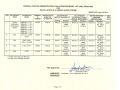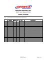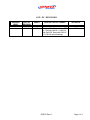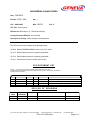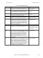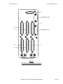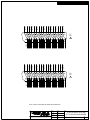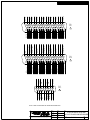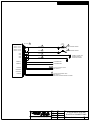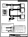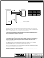
1
P139-HD DIGITAL AUDIO SYSTEM BELL 204 / 212/ 412 INSTALLATION MDL GA212 Rev A 19717 62 ND Ave. South, Suite E-101, Kent, WA 98032 STC SR02270SE Tel: 800 546 2210 or +1 253 395 9105 Fax 800 546 2220 LEGAL NOTICE The information contained in this document is provided solely under the condition that the Recipient of this document agrees to the terms and conditions of the Non-Disclosure and Proprietary Rights Agreement listed below. By accessing this document past this page, you are agreeing to be bound by this Non-Disclosure and Proprietary Rights Agreement. Non-Disclosure and Proprietary Rights Agreement Recipient recognizes and acknowledges that Eagle Copters USA and its affiliates (“Eagle”) possess certain Proprietary information and materials, which constitute a valuable, special, and unique asset of Eagle. As used herein, the term “Proprietary information and materials” includes, without limitation, all information and materials belonging to, used by, or in the possession of Eagle relating to its products, processes, technology, inventions, patents, developments, and trade secrets of every kind and character, but shall not include: (1) Information that was already in the public domain, (2) Information that subsequently becomes public domain through no act or omission by the Recipient. Recipient hereby acknowledges that all of the Proprietary information and materials are and shall continue to be the exclusive property of Eagle, whether or not disclosed to or entrusted to the custody of Recipient. Recipient further hereby acknowledges that all Proprietary information and materials have been disclosed or made available to him solely for the purpose of assisting him in incorporating, using, or maintaining equipment provided by Eagle. Recipient hereby agrees not to disclose, or allow to be disclosed, any Proprietary information or material of Eagle, in whole or in part, to any person or entity, for any reason or purpose whatsoever. Recipient further agrees that Recipient shall not use any Proprietary information or materials of Eagle for Recipient’s own purposes or for the benefit of any other person or entity except Eagle, whether such use consists of duplication, removal, oral use or disclosure, the transfer of any Proprietary information or materials in any manner, or any other unauthorized use, unless given prior written consent by Eagle. Recipient further agrees that Recipient will not allow the reverse engineering of any Eagle products. Recipient further agrees that Recipient shall use information provide, for installation or application, to one aircraft only for each product purchased, unless the purchase agreement specifically authorizes the use on more than one aircraft. Continuing past this page constitutes acceptance of the above agreement. (End of Agreement) Page 1 of 1 MASTER DRAWING LIST GA212 Rev A Dated 6/13/2013 AUDIO SYSTEM NOTE: LR X X IN LR COLUMN INDICATES CHANGE FROM LAST REVISION LEVEL. DRAWING NO. GA212-3 GA212-4 GA1-2TP G12019 G12100 G12260 G12347 G13000 G13004 G13006-2 G13006-4 G13008 G13009 G13009-1 G13009-2 G13009-3 G13045 G13046 G13115 G13116 TOTAL SHT REV DATE 15 16 7 1 3 1 1 1 13 1 1 1 1 1 1 1 1 3 1 1 NC A C C D --D F B A --A A --A A A 3/25/13 6/13/13 5/13/12 05/09/06 11/21/07 9/23/03 3/14/03 11/30/12 12/03/12 1/13/12 1/13/12 3/02/12 1/13/12 4/11/12 4/11/12 1/13/12 10/14/09 11/03/09 10/15/12 10/15/12 DESCRIPTION P139-HD Bell 204 – 412 Installation Manual P139-HD EC145 Installation Manual EMI Test Procedure Cable, GNET, Standard Connector And Wire Part List SWIF12T Auxiliary Control Module P139-HD Router P139-HD Audio System Wiring Diagrams Clip Doubler P139-HD Bell 204 – 412 Installation Tray Assy Tray Brace Shim Audio Mixing Amplifier Audio Mixing Amplifier Installation Control Panel Control Panel GA212 Rev A Page 1 of 2 LOG OF REVISIONS REVISION LEVEL -A DATE OF REVISION 3/25/13 6/13/13 PAGES All Pages All DESCRIPTION OF CHANGE APPROVAL Initial Release Removed EC135 Model from STC by: Revising GA212-1, GA212-2 and GA212-4, Removed ICA2122, G130130 series drawings. CLB CLB GA212 Rev A Page 2 of 2 ENGINEERING CHANGE ORDER Date: 3/26/2014 ECO No: ECO- 1518 Rev: -- STC: SR02270SE MDL: GA212 Rev: A STC Title: Audio System Effective for: Production; or Listed Aircraft Only: Primary Document Effected: See list below Description of Change: Minor changes to drawings listed Detailed Explanation: This ECO corrects minor changes to the drawings listed. G13004: Rewrote EMERG/NORMAL notes on sht 13 for clarity. G13115: Revised labeling notes to engineering standards. G13116: Revised labeling notes to engineering standards. G13121: Corrected part number on back shell on sht 2. ECO DOCUMENT LIST NOTE: X in CH (change) column indicates change from last revision level. Documents with multiple pages, that have a different revision level on some pages, are listed by individual pages on this list. CH X X X X DOC No. G13004 G13115 G13116 G13121 PAGES 13 1 1 3 REV G B B A DATE 3/26/14 3/26/14 3/26/14 3/26/14 DESCRIPTION P139-HD Audio System Wiring Diagrams Audio Control Panel Audio Control Panel Audio Mixer Installation Instructions ECO LOG OF REVISIONS REVISION LEVEL DATE OF REVISION PAGES - 3/26/2014 ALL 19717 62 ND DESCRIPTION OF CHANGE Initial Release Ave. South, Suite E-101, Kent, WA 98032 Tel: 800 546 2210 or +1 253 395 9105 ECO-1518 GA212.doc APPROVAL CLB Fax 800 546 2220 Page 1 of 1 ENGINEERING CHANGE ORDER Date: 5/08/2014 ECO No: ECO- 1520 Rev: -- STC: SR02270SE MDL: GA212 Rev: A STC Title: Audio System Effective for: Production; or Listed Aircraft Only: Primary Document Effected: See list below Description of Change: Adds audio system configurations STC Detailed Explanation: This ECO defines three audio system configurations as follows: P139-HD (D) Uses Router G13000 in a “Dual-board” configuration. This is the standard audio system that was previously specified in the STC and is shown in the diagrams. The G13000 is the primary router used throughout the instructions. P139-HD (S) has been added as an optional system configuration. It uses Router G13000 in a “Single-board” configuration that uses the same case as the dual-board router, but with only one audio board installed. These two routers share the same installation and wiring drawings. P139-HD (T) has been added as an optional system configuration. It uses Router G13160 and is a “Three board” router. This installation replaces wiring drawing G13004 with drawing G13162. Installation of this router is performed the same as the others two routers with slight changes in the mounting hardware as noted in the instructions. The G13160 router supports more radios, control panels and headsets than what the G13000 provides. This change is considered a minor change since the primary functionality of the system has not changed; there is negligible change to weight, balance and power consumption; and there are no changes required for the RFMS. To support this change: GA212-3 & GA212-4 have been revised to: add Section 1.3 defining the configurations; Revised the wording throughout the manual to define the installation differences between the different configurations. Updated the control panels section to show just the current panels offered. Figures throughout the manual have been updated for continuity. G13004 has been updated to change the headset numbering scheme and to add external power for additional control panels. G13160 Router drawing has been added for the three board router. G13161 Tray has been added to be used in place of Tray G13009 for the G13160 Router. G13161-1, -2, -3, & -4 detail drawings have been added. 19717 62 ND Ave. South, Suite E-101, Kent, WA 98032 Tel: 800 546 2210 or +1 253 395 9105 ECO-1520 GA212.doc Fax 800 546 2220 Page 1 of 2 G13162 wiring diagrams have been added to be used in place of G13004 for the G13160 Router. ECO DOCUMENT LIST NOTE: X in CH (change) column indicates change from last revision level. Documents with multiple pages, that have a different revision level on some pages, are listed by individual pages on this list. CH X X X X X X X X X X DOC No. GA212-3 GA212-4 G13004 G13160 G13161 G13161-1 G13161-2 G13161-3 G13161-4 G13162 PAGES 18 17 13 1 1 1 1 1 1 13 REV A B H -------- DATE 4/23/14 4/23/14 4/24/14 12/9/13 12/12/13 12/12/13 12/12/13 12/12/13 12/12/13 3/27/14 DESCRIPTION P139-HD Installation Instructions, Bell 204/412 P139-HD Installation Instructions, EC145 P139-HD Audio System Wiring Diagrams P139-HD 3-Board Router Wide Tray Assy Wide Tray Wide Brace Wide Shim Wide Clip P139-HD Audio System Wiring Diagrams ECO LOG OF REVISIONS REVISION LEVEL DATE OF REVISION PAGES - 5/08/2014 ALL 19717 62 ND DESCRIPTION OF CHANGE Initial Release Ave. South, Suite E-101, Kent, WA 98032 Tel: 800 546 2210 or +1 253 395 9105 ECO-1520 GA212.doc APPROVAL CLB Fax 800 546 2220 Page 2 of 2 ENGINEERING CHANGE ORDER Date: 8/13/2014 ECO No: ECO- 1532 Rev: -- STC: SR02270SE MDL: GA212 Rev: A STC Title: Audio System Effective for: Production; or Listed Aircraft Only: Primary Document Effected: See list below Description of Change: Updates Routers Detailed Explanation: This ECO updates Audio Routers G13000 and G13160 to change the operating voltage from 10 – 30 VDC to 14 – 32 VDC. ECO DOCUMENT LIST NOTE: X in CH (change) column indicates change from last revision level. Documents with multiple pages, that have a different revision level on some pages, are listed by individual pages on this list. CH X X DOC No. G13000 G13160 PAGES 1 1 REV E A DATE 8/13/14 8/13/14 DESCRIPTION P139-HD Router P139-HD 3 Board Router ECO LOG OF REVISIONS REVISION LEVEL DATE OF REVISION PAGES - 8/13/2014 ALL 19717 62 ND DESCRIPTION OF CHANGE Initial Release Ave. South, Suite E-101, Kent, WA 98032 Tel: 800 546 2210 or +1 253 395 9105 ECO-1532 GA212.doc APPROVAL CLB Fax 800 546 2220 Page 1 of 1 Geneva Aviation, Inc. www.GenevaAviation.com GA212-3 Revision A, 4/23/2014 P139-HD Digital Audio System Bell 204 / 412 Installation Manual GA212-3 Rev A P139-HD Digital Audio System 1 of 18 Geneva Aviation, Inc. 1.0 www.GenevaAviation.com INTRODUCTION 1.1. This document provides general information and instructions for the installation of the Geneva P139-HD Digital Audio System, under STC SR02270SE. 1.2. Installation is to be accomplished in accordance with Geneva Aviation instructions. Throughout the installation of this product it is necessary to utilize proper aviation practices. Be sure that the installation of this product is in compliance with the aircraft manufacturer’s limitations and also that it is done in accordance FAA publication, AC 43.13-1B, Acceptable Methods, Techniques and Practices, Aircraft Inspection and Repair. These rules from the AC apply : A. B. C. D. E. F. G. H. All wire to be 22 AWG unless otherwise specified. Unshielded wire per MIL-W-22759/16; Shielded wire per MILM27500-xxTGxT14 ; xx- indicates wire gauge, x- indicates number of conductors. Route and support wiring harness IAW AC 43.13-1b, Chapter 11 Section 8, Paragraph 11-96. Clamp wiring harness IAW AC 43.13-1b, Chapter 11, Section 11, Paragraph 11-146. Clamp and route wiring harness around movable controls IAW AC 43.13-1b, Chapter 11, Section 9, Paragraph 11-125. Wiring and harness to be separated IAW AC 43.13-1b, Chapter 11, Section 8, Paragraph a 11-105 & 11-106. Install service loops at harness terminations IAW AC 43.13-1b, Chapter 11, Section 9, Paragraph 11-139. Install grounding connections and bonding IAW AC 43.13-1b, Chapter 11, Section 15, Paragraph 11-186 & 11-189. Before installing any of the components, first read through all of the documentation to become familiar with the installation requirements. This installation requires a completed FAA Form 337 and appropriate log book entries. Prior to installing each component, record weight and mounting location in the aircraft’s weight and balance record. This product is provided with an FAA STC for certain aircraft models. If your installation is not covered by one of the models listed on the STC, then you may need to obtain a field approval from your local FAA Flight Standards District Office (FSDO). GA212-3 Rev A P139-HD Digital Audio System 2 of 18 Geneva Aviation, Inc. www.GenevaAviation.com The P139-HD Digital Audio Router contains no user serviceable internal components. Do not disassemble router or the factory warranty will be voided. For service, return the unit to Geneva Aviation. 1.3. There are three types of P139-HD Audio Systems that the installer may choose to install at their discretion. 1.3.1. P139-HD (D) Uses Router G13000 in a “Dual-board” configuration and is shown in the diagrams and is the router used throughout the instructions. 1.3.2. P139-HD (S) Uses Router G13000 in a “Single-board” configuration that uses the same case as the dual-board router, but with only one audio board installed. These two routers share the same installation and wiring drawings. 1.3.3. P139-HD (T) uses Router G13160 and is a “Three board” router. This installation replaces wiring drawing G13004 with drawing G13162. Installation of this router is performed the in the same manner as the other two routers with slight changes in the mounting hardware as noted in the instructions. 1.4. Prior to installation of this system, it is the responsibility of the installer to confirm by analysis or measurement, that the additional power requirement will not exceed the capacity of the avionics bus or the aircraft’s electrical system. Power consumption for this audio system is 5 amps at 28 volts. The system is designed to use redundant power sources, both coming from the master avionics bus. For each supply line, use a separate 5 amp fuse or circuit breaker on a 28 volt aircraft and separate ground lines to two separate ground points. Refer to G13004 for wire harness details. The system will support supply voltages of 14 – 32 VDC. 1.5. DC Power connections for the Audio System are listed in Table 1 by model. Serial number breaks relative to those models are also referenced where applicable differences in electrical configuration warrant different interconnects for DC Power. It is the installer’s responsibility to evaluate the applicability of the data in Table 1 prior to installation of the Audio System. It is also the responsibility of the installer to ensure that the installation does not interfere with any existing approved electrical modifications relative to installation of the Audio System or any associated electrical bus. GA212-3 Rev A P139-HD Digital Audio System 3 of 18 Geneva Aviation, Inc. www.GenevaAviation.com Table 1 Model Specific Notes Model Bell 204B Condition and Interconnect Method Does not exceed current limits of existing factory configuration. Verify Compliance using Section 1.3 Reference Attachment BHT-204B-M&O ELA Chart 9-8 and Graph 9-6. S/N: 2001-2060 Remove Existing ICS Amplifier and Speaker Amplifier 5 Amp Circuit Breakers. Install single 5 Amp CB for Geneva Audio System to the existing 28V DC Bus. BHT-204B-M&O Page 11-38 and 11-46. S/N: 2061-Sub Remove Existing AirComm Audio System 5 Amp Circuit Breakers. Install single 5 Amp CB for Geneva Audio System to the existing 28V DC Bus. BHT-204B-M&O Page 11-38 and 11-46. Bell 205 Does not exceed current limits of existing factory configuration. Verify Compliance using Section 1.3 BHT-205A1-MM-2 Section 96 Page 9-13 and Figure 9-2. S/N: All Use Existing Pilot Audio Panel 5 Amp Circuit Breaker on 28V DC Bus #2. Connect Power #1 of Geneva Audio System to this Breaker. Use Existing Co-Pilot Audio Panel 5 Amp Circuit Breaker on 28V DC Bus #1. Connect Power #2 of Geneva Audio System to this Breaker. Note: This configuration provides redundant power from 2 separate buses. BHT-205A1-MM-2 Section 98. Figure 98-7 Sht 1. Bell 212 Does not exceed current limits of existing factory configuration. Verify Compliance using Section 1.3 BHT-212-MM-10 Chapter 96. Para. 96-1, 96-1A, 96-2A, 962B. BHT-212-MM-10 Chapter 98. Figure 98-7. S/N: 3050430553 Remove Existing Pilot Intercom 1 Amp Circuit Breaker and Cabin Intercom 1 Amp Circuit Breaker on 28V DC Bus #1. Install a single 5 Amp Circuit Breaker. Connect Power #1 of Geneva Audio System to this Breaker. Remove Existing Co-Pilot Intercom 1 Amp Circuit Breaker and Speaker Amplifier 3 Amp Circuit Breaker on 28V DC Bus #2. Install single 5 Amp Circuit Breaker. Connect Power #2 of Geneva Audio System to this Breaker. Remove Existing Pilot Intercom 1 Amp Circuit Breaker and Cabin Intercom 1 Amp Circuit Breaker on 28V DC Bus #1. Install a single 5 Amp Circuit Breaker. Connect Power #1 of Geneva Audio System to this Breaker. Remove Existing Co-Pilot Intercom 1 Amp Circuit Breaker on 28V DC Bus #2. Install single 5 Amp Circuit Breaker. Connect Power #2 of Geneva Audio System to this Breaker. Note: This configuration provides redundant power from 2 separate buses. BHT-212-MM-10 Chapter 98. Figure 98-8 Sht 4. S/N: 30554Sub. BHT-212-MM-10 Chapter 98. Figure 98-9 Shts 8 & 9. GA212-3 Rev A P139-HD Digital Audio System 4 of 18 Geneva Aviation, Inc. www.GenevaAviation.com Table 1 Model Specific Notes cont. Model Bell 214 Condition and Interconnect Method Does not exceed current limits of existing factory configuration. Verify Compliance using Section 1.3 Reference Attachment BHT-214ST-FM Page 1-16. BHT-214ST-MM-10 Chapter 96. Figure 96-1. S/N: All Use Existing Pilot ICS 5 Amp Circuit Breaker on 28V DC Emergency Bus #2. Connect Power #1 of Geneva Audio System to this Breaker. Use Existing Co-Pilot ICS 5 Amp Circuit Breaker on 28V DC Essential Bus #1. Connect Power #2 of Geneva Audio System to this Breaker. Note: This configuration provides redundant power from 2 separate buses. BHT-214ST-MM-10 Chapter 98. Figure 98-29 Shts 5 & 7. Bell 412 Does not exceed current limits of existing factory configuration. Verify Compliance using Section 1.3 BHT-412-MM-12 Chapter 98. Section 98-08. Figure 98-8. S/N: All Use Existing Pilot ICS 5 Amp Circuit Breaker on 28V DC Emergency Bus #2. Connect Power #1 of Geneva Audio System to this Breaker. Use Existing Co-Pilot ICS 5 Amp Circuit Breaker on 28V DC Essential Bus #1. Connect Power #2 of Geneva Audio System to this Breaker. Note: This configuration provides redundant power from 2 separate buses. BHT-412-MM-11 Chapter 97. Figure 97-7. Sheet 1. Figure 97-8. Sheet 2. 1.6. The internal power supply of the router is sufficient to power six audio control panels. If the installation calls for more than six panels, the additional panels must be powered from a separate circuit breaker to the Router. Refer to G13004 sheet 12 for more information. The FAA requirement regarding the securing of wire bundles using nonmetallic clamps is addressed by the use of nylon cable ties. The part numbers and description of these ties is as follows: Following the guidelines in AC43.13-1B, cable ties are attached at a maximum of 4” spacing and ties are attached to nylon cable tie anchors, as necessary. Cat. No. TY23M TY24M TY25M Max. Body Length Wire UPC Width In. Bundle In. Dia. In. 82436 .091 3.62 .625 82447 .140 5.50 1.125 82457 .184 7.31 1.750 Military Standard Part No. Tensile Strength Lb. MS3367-4 MS3367-5 MS3367-1 18 40 50 1.7. The aircraft into which this product will be installed may be a new aircraft or an aircraft that has been in service. The configuration of the wiring and GA212-3 Rev A P139-HD Digital Audio System 5 of 18 Geneva Aviation, Inc. www.GenevaAviation.com cabling will vary from aircraft to aircraft. The installation of the Geneva Aviation Audio System should use existing wire and cable runs when possible as it will not interfere with the existing aircraft wiring. 1.8. These instructions call out cables by reference to the drawing that defines the cable construction details. The installer may, at the installer’s discretion, substitute connectors, wire type, and connection details, so long as the final installations operate correctly and meets FAA standards. 1.9. The Router features a COM1 Isolate mode that automatically connects the pilot’s headset and mic switches directly to COM1 in the event of power loss or failure of the Audio Router. The pilot may also activate the COM1 Direct mode using the EMERG/NORMAL switch on the G13115 and G13116 control panels. This feature may also be set up for the Copilot to activate a COM2 Isolate mode using the EMERG/NORMAL switch on the copilot control panel. 1.10. For Non-Pilot positions, Control Panels G13115NS or G13116NS may be used. The panels do not have an internal COM1, COM2 isolate switch. For these panels, do not connect to the COM1 or COM2 circuits shown in wiring diagrams G13004. GA212-3 Rev A P139-HD Digital Audio System 6 of 18 Geneva Aviation, Inc. 2.0 www.GenevaAviation.com System Overview Figure 1 Digital Audio System Overview 2.1. The schematic shown in Figure 1 is a typical system. The installer may, at the installer’s discretion, add or remove radios, control panels, headset groups, or ICS and Transmit PTT switches as needed. 2.2. Control Panels G13115 and G13116 may be used interchangeably, depending on the control functions desired and number of radios installed. 2.3. It is the installer’s responsibility to document the system configuration as installed for maintenance purposes. GA212-3 Rev A P139-HD Digital Audio System 7 of 18 Geneva Aviation, Inc. 3.0 www.GenevaAviation.com Component Installation & Hookup J5 J6 NETWORK PORT J1 J2 J7 MEMORY PORT J4 J3 Figure 2 G13000 Router Connector Layout GA212-3 Rev A P139-HD Digital Audio System 8 of 18 Geneva Aviation, Inc. www.GenevaAviation.com 3.1. G13000 Router Connections (see Figure 2) 3.1.1. J1 is used to connect COM1 and radios XCVR3 – XCVR11. 3.1.2. J2 is used to connect COM2 and radios XCVR12 – XCVR20. 3.1.3. J3 is used to connect the Pilot’s control panel, Pilot’s headset group, headset groups 3 – 7 and passenger control panels. 3.1.4. J4 is used to connect the Copilot’s control panel, Copilot’s headset group, headset groups 8 – 12 and additional passenger control panels. 3.1.5. J5 is used to connect power, ground, Pilot’s COM1 Isolate, and Copilot’s COM2 Isolate. 3.1.6. J6 is a network port used for system configuration adjustment. 3.1.7. J7 is a memory card slot used for storing system configuration data onto removable media. 3.1.8. The Router contains no user serviceable internal components. Do not disassemble router or the factory warranty will be voided. Return the unit to Geneva Aviation for service. GA212-3 Rev A P139-HD Digital Audio System 9 of 18 Geneva Aviation, Inc. www.GenevaAviation.com J7 J8 NETWORK PORT J5 J1 J3 J9 MEMORY PORT J2 J6 J4 Figure 3 G13160 Router Connector Layout GA212-3 Rev A P139-HD Digital Audio System 10 of 18 Geneva Aviation, Inc. www.GenevaAviation.com 3.2. G13160 Router Connections (see Figure 3) 3.2.1. J1 is used to connect radios COM1 and radios XCVR3 – XCVR11. 3.2.2. J2 is used to connect the Pilot’s control panel, Pilot’s headset group, headset groups 3 – 7 and passenger control panels. 3.2.3. J3 is used to connect radios COM2 and radios XCVR12 – XCVR20. 3.2.4. J4 is used to connect the Copilot’s control panel, Copilot’s headset group, headset groups 8 – 12 and additional passenger control panels. 3.2.5. J5 is used to connect radios XCVR21 – XCVR30. 3.2.6. J6 is used to connect headset groups 13 – 18 and additional passenger control panels. 3.2.7. J7 is used to connect power, ground, Pilot’s COM1 Isolate, and Copilot’s COM2 Isolate. 3.2.8. J8 is a network port used for system configuration adjustment. 3.2.9. J9 is a memory card slot used for storing system configuration data onto removable media. 3.2.10. The Router contains no user serviceable internal components. Do not disassemble router or the factory warranty will be voided. Return the unit to Geneva Aviation for service. GA212-3 Rev A P139-HD Digital Audio System 11 of 18 Geneva Aviation, Inc. www.GenevaAviation.com 3.3. Component Installation & Hookup Router Installation in Avionics Shelf 3.3.1. Refer to drawing G13008 for installing the Router into the FWD Avionics Shelf. 3.3.2. Note: for the G13160 Router replace in G13008 the following items: G13009 with G13161; G13009-3 with G13161-3; G13006-2 with G13161-4 and use (3) MS24693S51 screws to install; use (2) NAS622CE2 Support Hooks. 3.3.3. Location shown is for reference only. The exact placement is dependant on other pre-existing equipment installed. It is the installer’s responsibility to make sure this installation does not interfere with other installed equipment. 3.3.4. Optionally, the installer may, at the installer’s discretion, install the router box into an alternate avionics bay or load rated structure. Its precise location is not critical to its function, however, it should not be located in an area that is exposed to the environment as the case is not environmentally sealed. Do not install near AC Inverters, or near other sources of heavy EMI. 3.3.5. For Router G13000, refer to drawing G13004 for the detailed wiring schematic used in this installation. For Router G13160, refer to drawing G13162 for the detailed wiring schematic used in this installation. 3.3.6. Be sure to carefully document the Radios and Control panels as installed and their related connections for future maintenance and troubleshooting purposes. GA212-3 Rev A P139-HD Digital Audio System 12 of 18 Geneva Aviation, Inc. www.GenevaAviation.com 3.4. Control Panels 3.4.1. The Control Panels mount onto standard DZUS rails and should be mounted in locations designed for standard avionics mounting. The control panels connect to the router via the 4-wire GNET bus. 3.4.2. There can be more than one of these control panels in any combination connected to the system. Each audio board has two GNET ports giving 2, 4, 6 GNET ports for the P139 (S)/(D)/(T) routers respectively. If the configuration calls for more control panels than there are available GNET ports on the router, connect J1 of each control panel to a GNET port in parallel for pins 1 – 4. Pins 5 – 9 will be unique ID for each control panel connector. See G13004 sheet 9 for details. 3.4.3. The pilot control panel also controls the COM1 Isolate function. Optionally the copilot control panel controls the COM2 isolate function. See Section 1.8 for more information. 3.5. Control Panels G13115 & G13115NS 3.5.1. The G13115 & G13115NS Control panels provide separate transmit, receive and volume controls for up to 16 radios or other devices, as well as crew intercom functions and optionally installer-defined special functions. The G13115NS version does not have an EMERG/NORMAL switch and must not be used as a pilot or copilot primary panel. GA212-3 Rev A P139-HD Digital Audio System 13 of 18 Geneva Aviation, Inc. www.GenevaAviation.com 3.6. Control Panels G13116 & G13116NS 3.6.1. The G13116 & G13116NS Control panels provide separate transmit, receive and volume controls for up to 8 radios or other devices, as well as crew intercom functions and optionally installer-defined special functions. The G13116NS version does not have an EMERG/NORMAL switch and must not be used as a pilot or copilot primary panel. 3.7. Headset Ports 3.7.1. The Pilot and Copilot Headset Group consists of the headset jack, ICS switch and transmit switches on the cyclic and/or foot switches. 3.7.2. For each passenger, a unique Passenger Headset Group is needed. The Passenger Headset Group consists of the passenger’s headset jack, an ICS switch and a transmit switch. GA212-3 Rev A P139-HD Digital Audio System 14 of 18 Geneva Aviation, Inc. www.GenevaAviation.com 3.8. COM1, COM2 and other radio ports 3.8.1. The G13000 digital audio router supports up to 20 radios and the G13160 router supports up to 30 radios. Each radio should be installed in accordance with the manufacturer’s instructions. 3.8.2. For the G13000 the following connections are available: 3.8.2.1. The COM1 radio connects to J1 on the Router along with radios XCVR3 - XCVR11 (refer to G13004 sheet 4). 3.8.2.2. The COM2 radio connects to J2 on the router along with radios XCVR12 - XCVR20 (refer to G13004 sheet 5). 3.8.3. For the G13160 the following connections are available: 3.8.3.1. The COM1 radio connects to J1 on the Router along with radios XCVR3 - XCVR11 (refer to G13162 sheet 5). 3.8.3.2. The COM2 radio connects to J3 on the router along with radio ports XCVR12 - XCVR20 (refer to G13162 sheet 6). 3.8.3.3. Radios XCVR21 - XCVR30 connect to J5 on the router (refer to G13162 sheet 7). 3.8.4. While the term radio is used throughout this document, any type of audio device can be connected, such as tape recorders, scanners, telephones, hand-held radios, etc. There is normally no need for any type of universal radio adapter between an audio device and the router. GA212-3 Rev A P139-HD Digital Audio System 15 of 18 Geneva Aviation, Inc. 4.0 www.GenevaAviation.com Functional Check 4.1. Perform a check of all power and ground leads to confirm they are connected properly before applying power to the system. Incorrect wiring may cause damage to the units. 4.2. Connect headset adapter cables, headsets and switches. Apply power to audio system, radios and related accessories. Activate ICS and confirm proper operation. Place ‘PILOT EMERG/NORMAL’ switch in ‘EMERG’ position. Key transmit switch and confirm proper operation of COM1. 4.3. Place the ‘PILOT EMERG/NORMAL’ switch in ‘NORMAL’ position and check all transceivers, receivers and audio devices. 4.4. If the system is equipped with a ‘COPILOT EMERG/NORMAL’ switch, repeat the steps in sections 4.2 and 4.3 for Copilot position and COM2 respectively. 4.5. Check all pilot, copilot and passenger audio control panels for proper audio levels and operation. Should adjustments be required, follow the instructions in document GA063-3. GA212-3 Rev A P139-HD Digital Audio System 16 of 18 Geneva Aviation, Inc. 5.0 www.GenevaAviation.com Load Analysis 5.1. At the completion of the installation of the audio system, the installer shall perform a load analysis test of the electrical branch circuit that powers the audio system, and also the entire aircraft electrical load, to confirm that the addition of the audio system will not cause an overload to the electrical branch circuit or the aircraft generator. 5.2. The current shall be measured using a properly calibrated ammeter. A clamp-on amp meter, such as Amprobe Instrument model number ACDC600A, or equivalent will make this job easier. 5.3. Perform the branch circuit load analysis test by powering up all equipment that is intended to be operated at the same time on the branch circuit that the audio system is connected to. Additionally, key the three highest power communication transmitters at the same time, if possible, while the current measurements are being taken. 5.4. Measure the current of the branch circuit powering the audio system, by clamping the meter around the branch circuit wire near its origin. Confirm that the current draw during the above described test conditions is less than the current limiter (fuse or circuit breaker) rating for that branch circuit. 5.5. If the current draw is greater than the current limiter rating, it becomes the installer's responsibility to re-distribute some of the other equipment powered by this branch circuit to another suitable branch circuit, in order to reduce the load on the audio system's branch circuit to less than the current limiter rating. 5.6. Once the branch circuit loads are within limits, test the current load for the entire aircraft while all power for the aircraft is being supplied by the aircraft generator, battery, or external power source. Perform this load analysis test by powering up all equipment on the aircraft that is intended to be operated at the same time as the audio system. Additionally, key the three highest power communication transmitters at the same time, if possible, while the current measurements are being taken. Clamp the ammeter around the power source. Confirm that the current draw during the above described test is less than the generator rating. 5.7. Upon satisfactory completion of these load analysis tests, make an aircraft logbook entry that these tests have been performed satisfactorily in accordance with this STC. GA212-3 Rev A P139-HD Digital Audio System 17 of 18 Geneva Aviation, Inc. 6.0 www.GenevaAviation.com Interference Test Procedure 6.1. Perform electrical interference test using GA1-2TP test procedure. 7.0 Final Inspection 7.1. Perform final inspection of installation confirming: 7.1.1. There are no chaffing issues. 7.1.2. There are no mechanical interference issues. 7.1.3. Security of fasteners. 7.1.4. Removal of all tools. 7.1.5. Chips, shavings and other debris are removed. 7.1.6. Proper reassembly of aircraft. 7.1.7. Aircraft is airworthy prior to returning to service. 8.0 FAA Requirements 8.1. Amend the weight and balance records and make the necessary log book entry. Complete an FAA form 337 showing the installation of this equipment in accordance with the STC instructions and submit one copy to the FAA and one copy to the aircraft owner. File all data and a copy of the STC with the aircraft records. LOG OF REVISIONS REVISION LEVEL NC A DATE OF REVISION 3/25/13 4/23/14 PAGES DESCRIPTION OF CHANGE All Pages Initial Release ALL Added G13160 3-Board Router GA212-3 Rev A P139-HD Digital Audio System APPROVAL CLB CLB 18 of 18 GA1-2TP REV: C 5/13/2012 EMI Test Procedure 19717 62ND Ave. South, Suite E-101, Kent, WA 98032 Tel: 800 546 2210 or +1 253 395 9105 GA1-2TP Rev C Fax 800 546 2220 Page 1 of 7 LOG OF REVISIONS REVISION LEVEL A B C DATE OF REVISION PAGES DESCRIPTION OF CHANGE 8/08/1997 9/08/1997 10/16/1998 ALL 2 3, 4 5/13/2012 ALL Initial Release Added “LIST OF REVISIONS” Page Added coverage for FADEC aircraft under Scope. Revised procedure under Transponder test. Revised Scope to remove FADEC references; Revised FAR references to CFR; Updated checklist for “other” equipment; Updated format of document to current standards; GA1-2TP Rev C APPROVAL GLH GLH GLH CLB Page 2 of 7 Scope This document is a test plan to be used to establish that newly installed electrical equipment does not interfere with essential aircraft equipment in any way that would impair safety of flight of the aircraft. Satisfactory completion of this test plan confirms that the newly installed equipment satisfies the EMI requirements of the Federal Aviation Administration. This test plan is applicable to FAR part 29 Rotorcraft. Applicable Documents CFR 29.1309(c), 29.1351(b)(1), 29.1351(b)(2) and AC25-10 Paragraph 5, sections: (m)(4) & (n). Witnessing of EMI Test This test shall be witnessed by someone who is authorized by the FAA to return the aircraft to service. This would include an FAA licensed Avionics Technician, A&P Mechanic, Inspector of Airworthiness, or the Repair Station’s Director of Maintenance. In addition, an FAA representative, such as a DAR or DER may witness the test. Equipment Under Test The newly installed Equipment Under Test (EUT) by this test plan shall be in proper working order throughout the test. If the EUT fails during this test, then this test shall be repeated with the EUT in proper working order. Test Procedure Testing shall normally be conducted with the aircraft running on the ground, or with battery or external ground power where appropriate. In the event that an aircraft system or component can only be evaluated for the effects of interference with the aircraft in flight, then the evaluation of that system or component shall be conducted with the aircraft in flight. Testing conducted with the aircraft in flight shall be performed with safety of flight in mind and with only necessary personnel on board. Testing shall be conducted on the aircraft with all aircraft systems and equipment operating normally, and cycled as necessary to conduct the test. The EUT shall be operated normally. The EUT shall be cycled on and off. The EUT shall also be cycled through all of its operating modes. Each aircraft system or component being evaluated for the effects of EMI will be observed as the EUT is cycled. A transient motion or flicker is acceptable provided no permanent deviation is established. There can be no stand-off conditions displayed on an instrument. In the case of audio equipment being evaluated for the effects of EMI, a change in the audio (such as background noise) that does not interfere with the intended purpose of the audio is acceptable. For each aircraft system or component being evaluated for the effects of EMI, mark the item as PASS or FAIL based upon the outcome of this test procedure. If an aircraft system or component being evaluated for the effects of EMI Fails this test procedure, then corrective action must be taken to reduce the interference to an acceptable level which allows the aircraft system or component being evaluated for the effects of EMI to PASS this test. When retesting after corrective action, the only tests to be repeated are the tests that Failed previously. Items that previously Passed do not need to be re-tested, unless the method of corrective action results in changes to the EUT, which might cause the EUT to Fail previously Passed items. Mark the N/A __ field on the re-test test plan for the items that previously Passed and are not being retested. GA1-2TP Rev C Page 3 of 7 Items To Evaluate The following is a list of aircraft systems or components that must be evaluated for the effects of EMI if they are installed and are to be used at the same time as the EUT. If the item listed below is not installed or otherwise not applicable, then mark the N/A __ field. Engine Temperature Indicator Engine RPM Indicator Engine Torque Indicator Engine Fuel Control Engine Oil Pressure Indicator Engine Oil Temperature Indicator Rotor RPM Indicator Fuel Quantity Indicator Fuel Pressure Indicator Generator Voltage Indicator Battery Voltage Indicator Directional Gyro / Heading Indicator Attitude Indicator Turn and Bank Indicator Annunciator Indicators Flight Time Hour Meter Warning Horn Outside Air Temperature Indicator N/A __ N/A __ N/A __ N/A __ N/A __ N/A __ N/A __ N/A __ N/A __ N/A __ N/A __ N/A __ N/A __ N/A __ N/A __ N/A __ N/A __ N/A __ Pass __ Pass __ Pass __ Pass __ Pass __ Pass __ Pass __ Pass __ Pass __ Pass __ Pass __ Pass __ Pass __ Pass __ Pass __ Pass __ Pass __ Pass __ Fail __ Fail __ Fail __ Fail __ Fail __ Fail __ Fail __ Fail __ Fail __ Fail __ Fail __ Fail __ Fail __ Fail __ Fail __ Fail __ Fail __ Fail __ Transponder N/A __ Pass __ Fail __ Set controls to mode C code 1200, or other code assigned by ATC. Cycle EUT and confirm proper data transmitted, either by use of transponder ground test equipment, or by confirmation from ATC of proper reception of correct data. Check for proper operation of reply light. VOR N/A __ Pass __ Fail __ Set Voice/Ident to Voice. Check frequencies for audible interference sounds. Set local VOR frequency for full needle displacement. Adjust course select knob for gradual reduction of needle displacement to half, fourth, and zero. Note stability at each displacement and that zero can be achieved without a standoff. DME N/A __ Pass __ Fail __ Perform self test with EUT cycled. Note that no skips in miles display occurs. Observe that mile indications do not drift and there is no audible interference in Ident tone. Magnetic Compass N/A __ Pass __ Fail __ Swing compass and adjust with EUT operating normally. If EUT causes erratic operation of magnetic compass, then mark compass as Fail. GA1-2TP Rev C Page 4 of 7 VHF Communications System N/A __ Pass __ Fail __ Tune each comm receiver to a low, middle, and high frequency within its frequency range. Listen for audio interference. Transmit on low, middle, and high frequencies. Listen on an external receiver for audio interference. GPS Navigation Receiver N/A __ Pass __ Fail __ Check for proper operation. Observe signal to noise ratio readings to determine if reception is interfered with. Crew Interphone System N/A __ Pass __ Fail __ Check for normal operation of the interphone system. Listen for excessive background noise. ADF N/A __ Pass __ Check for needle offset. Listen for audio interference. Fail __ Glide Slope/LOC N/A __ Pass __ Fail __ Check for needle offset. Perform test using TAC/30b or equivalent ground test equipment, or during flight while established on an ILS glide slope. Radio Altimeter N/A __ Pass __ Fail __ Perform test with appropriate ground test equipment, or check reading in flight. The space below is provided to include additional systems or devices not listed previously. These would include any Transceivers, Nav Aids, Radar, or Auto Pilot systems. Use the Manufacturers test procedures for each component listed with the EUT operating normally. Other Equipment: _________________ N/A __ Pass __ Fail __ Describe test: _____________________________________________________ ________________________________________________________________ Other Equipment: _________________ N/A __ Pass __ Fail __ Describe test: _____________________________________________________ ________________________________________________________________ Other Equipment: _________________ N/A __ Pass __ Fail __ Describe test: _____________________________________________________ ________________________________________________________________ GA1-2TP Rev C Page 5 of 7 Other Equipment: _________________ N/A __ Pass __ Fail __ Describe test: _____________________________________________________ ________________________________________________________________ Other Equipment: _________________ N/A __ Pass __ Fail __ Describe test: _____________________________________________________ ________________________________________________________________ Other Equipment: _________________ N/A __ Pass __ Fail __ Describe test: _____________________________________________________ ________________________________________________________________ Other Equipment: _________________ N/A __ Pass __ Fail __ Describe test: _____________________________________________________ ________________________________________________________________ Other Equipment: _________________ N/A __ Pass __ Fail __ Describe test: _____________________________________________________ ________________________________________________________________ Other Equipment: _________________ N/A __ Pass __ Fail __ Describe test: _____________________________________________________ ________________________________________________________________ Other Equipment: _________________ N/A __ Pass __ Fail __ Describe test: _____________________________________________________ ________________________________________________________________ Other Equipment: _________________ N/A __ Pass __ Fail __ Describe test: _____________________________________________________ ________________________________________________________________ GA1-2TP Rev C Page 6 of 7 Aircraft Tested: Model _______________, Registration ___________, Serial Number ______ Location of Test _______________________, Date _____________ Equipment Under Test: List: MODEL, PART NUMBER, SERIAL NUMBER _________________________________________________________________ _________________________________________________________________ _________________________________________________________________ _________________________________________________________________ __________________________________________________________________ __________________________________________________________________ __________________________________________________________________ __________________________________________________________________ Test performed by ________________________________________________ Name Credentials Test witnessed by ________________________________________________ Name Credentials I hereby certify that I have witnessed the above documented test and that the results documented above reflect my observations. _______________________ Signature _______________________ Date GA1-2TP Rev C Page 7 of 7 3 4 D 1 2 REVISIONS REV J5 G13000 P139-HD ROUTER WEIGHT = 5 LBS MAX POWER = 5 AMPS MAX VOLTAGE = 14 - 32 VDC J6 NETWORK PORT J2 J1 DESCRIPTION APPROVED/DATE A REVISED LABEL ON J7 5/12/09 CLB B ADDED SINGLE BOARD CONFIGURATION NOTE 6/10/11 CLB C REVISED FRONT SCREWS FOR G13009 TRAY 1/13/12 CLB D ADDED OPTIONAL FRONT AND BOTTOM CLIPS FOR TRAY INSTALLATION 11/30/12 CLB E VOLTAGE RANGE WAS 10 - 30 VDC 08/13/14 CLB D 10.00 J7 MEMORY CARD SLOT J4 C J3 C OPTIONAL: SUPPORT HOOK (NAS622CE2) INSTALLED WITH (2) #6-32 X .5 FLAT HEAD SCREWS (MS24693S28) AND NUTPLATES (MS21071L06) OR LOCKNUTS (MS21042L06) 8.50 B B 2.63 OPTIONAL SINGLE AUDIO BOARD CONFIGURATION: J1 AND J3 ARE REPLACED WITH COVER PLATE G13000-9 A OPTIONAL: CLIP G13006-2 INSTALLED WITH (2) #8-32 X .62 FLAT HEAD SCREWS (MS24693S51) AND NUTPLATES (MS21059L08) BREAK SHARP EDGES UNLESS OTHERWISE SPECIFIED DIMENSIONS ARE IN INCHES DRAWN CLB DATE CHECKED DATE Design DATE 10/30/08 TOLERANCES ARE: FRACTIONS DECIMAL ANGLES .X .050 2 1/8" .XX .030 .XXX .010 Title Approval CLB DATE 3 2 P139-HD ROUTER 10/30/08 THIS DOCUMENT INCLUDES INFORMATION PROPRIETARY TO GENEVA AVIATION AND SHALL NOT BE USED OR DUPLICATED BY ANYONE WITHOUT THE WRITTEN PERMISSION OF GENEVA AVIATION, INC. 4 A Drawing Number Pro No: G13000 GA182/212 1 SIZE REV D Scale: 1:1 E Sheet 1 of 1 AUDIO BOARD OPTIONS: REV A B C D E F The P139-HD can be set up in one of two configurations: -- Dual Audio Board system with 4 audio connectors J1, J2, J3, J4 -- Single Audio Board with 2 audio connectors J2 and J4 Pages 1, 11 and 12 are common to all installations. Wiring diagrams for the Dual Audio Board system are found on pages 2 through 7 Wiring diagrams for the Single Audio Board system are found on pages 8 through 10 REVISION DESCRIPTION Changed Connector Part Numbers Added Single Audio Board Option Added Wiring for G13115/G13116 Control Panel Added Alert Tone Information for EC135, EC145 Fixed Drawing Errors. Added G13115NS and G13116NS Updated for Installation in Bell Medium Helicopters DATE 5/28/09 6/10/11 3/02/12 4/16/12 10/29/12 12/3/12 APPROVAL GA GA GA SJC SJC SJC G Rewrote EMERG/NORMAL notes for clarity. Removed support for older control panels. 3/26/14 SJC H Changed headset numbering scheme Added external power for additional control panels. 4/24/14 SJC Wiring Diagram for using pysical switches on G13115/G13116 Control heads is on page 13. G13115NS or G13116NS may be substituted in any location besides Pilot or Co-Pilots locaction or may be used in any location if they are not the primary audio panel. NOTES: 1. Unless otherwise noted: All wires are 22 AWG; all shielded wire is MIL-DTL-27500; all unshielded wire is MIL-W-22759/16. 2. All Bonding and Grounding will be I/A/W AC 43.13-1B, Chapter 11, Section 15. 3 Ground the shield return to the metal connector backshell if used, or otherwise to the metal connector housing. 4 SPARE KEY line function and connections are installer defined and depend on the specific system configuration. 5 D50M connector assembly consists of: Tyco/AMP housing 205170-1 or 1757819-5; Tyco/AMP pin contacts 205089-1; Cinch backshell DD-24661-34; 2ea. Cinch Screwlocks D20420-0. Alternate Backshell: Conec 165X10179X. 6 D50F connector assembly consists of: Tyco/AMP housing 205169-1 or 1757820-5; Tyco/AMP socket contacts 205090-1; Cinch backshell DD-24661-34; 2ea. Cinch Screwlocks D20420-0. Alternate Backshell: Conec 165X10179X. 7 D9F connector assembly consists of: Tyco/AMP housing 205161-1 or 1757820-1; Tyco/AMP socket contacts 205090-1; Cinch backshell DE-24657-30; 2ea. Cinch Screwlocks D20419-46. Alternate Backshell: Conec 165X10139X. 8 When COM1DIR (P5, Pin 10) is not grounded, the Pilot headset is in EMERGENCY mode and the following lines are diverted: - HEADSET 1 connects directly to RX1, RX11 (Unswitched Alert Tones) and the emergency intercom. - MIC 1 connects directly to TX1 and the emergency Intercom. - XMIT KEY 1 and PLT COM1 KEY connect to TX KEY 1. - ICS KEY 1 keys the emergency intercom, if at least one Power Input Circuit Breaker to the G13000 Audio Router has power. - TX11 (CVR) transmits HEADSET1, MIC1 and Emergency Intercom if at least one Power Input Circuit Breaker to the G13000 Audio Router has power. When COM2DIR (P5, Pin 11) is not grounded, the Copilot headset is in EMERGENCY mode and the following lines are diverted: - HEADSET 2 connects directly to RX2, RX20 (Unswitched Alert Tones) and the emergency intercom. - MIC 2 connects directly to TX2, and the emergency Intercom. - XMIT KEY 2 and CPLT COM2 KEY connect to TX KEY 2. - ICS KEY 2 keys the emergency intercom, if at least one Power Input Circuit Breaker to the G13000 Audio Router has power. - TX20 (CVR) transmits HEADSET2, MIC2 and Emergency Intercom if at least one Power Input Circuit Breaker to the G13000 Audio Router has power. 9 TERMINAL BLOCK assembly consists of: Deutsch block CTJ122E05E; Deutsch socket contacts CTS-S22/22 or M39029/22-191. A GNET channel that is connected to only one control panel or other device may be wired directly without using a terminal block. 10 D15FS connector preferred assembly consists of: Tyco/AMP housing 205163-1 or 1757820-2; Tyco/AMP socket contacts 205090-1; Cinch backshell DA-24658-31; 2ea. Cinch Screwlocks D20419-46. Alternate Backshell: Conec P/N: 165X10149X. Splices on 20 AWG wire shall also be 20 AWG, length 3 inches maximum. Alternate assembly consists of: Kobiconn Solder-Cup Connector 156-1315(T-E) and Cinch backshell DA-24658-31; 2ea. Cinch Screwlocks D20419-46. Alternate Backshell: Conec P/N: 165X10179X. Conductors shown with splices may be implemented by soldering the supply wire to both pins after soldering and insulating the adjacent connections. 11 The Audio System works with a range of supply voltages, as specified in the installation instructions. Breaker ratings and wire sizes shown are for 28V systems. For 12V systems, the breaker ratings must be increased to 10A and the size of the shielded supply and ground wires must be increased to 18 AWG. The splice wires at P5 remain at 20 AWG. 12 D9M connector assembly consists of: Tyco/AMP housing 205162-1 or 1757819-1; Tyco/AMP socket contacts 205089-1; Cinch backshell DE-24657-30; 2ea. Cinch Screwlocks D20419-46. Alternate Backshell: Conec 165X10139X. 13 The COM1DIR pin MUST be wired to an appropriate switch to control Emergency Mode for the pilot headset. Emergency Mode is mandatory when the G13000 Audio Router is used as the primary audio system. See notes on sheet 13. 14 For EC135 connect alert tone ports to TB9 of factory wiring. See Eurocopter Maint.Manual WDM for detail. For EC145 connect alert tone ports to TB55028 of factory wiring. See Eurocopter Maint. Manual WDM for detail. For Bell 204, 205, 214 and 412 connect alert tone ports to 8Z1P3. See Bell Maint. Manual BHT-xx-MM for detail. DEFINITIONS: N/C: MAKE NO CONNECTION. The pin is not connected to anything internally and therefore shall have no connection externally RESERVED: MAKE NO CONNECTION. Internal circuitry may be added in the future, or may be present and relevant for testing but not relevant to operation for flight. DRAWN DATE RBH CHECKED TITLE 10/30/08 DATE JSW APPROVAL 10/30/08 DATE www.genevaaviation.com CLB THIS DOCUMENT INCLUDES INFORMATION PROPRIETARY TO GENEVA PRO NO. AVIATION AND SHALL NOT BE USED OR DUPLICATED BY ANYONE WITHOUT THE WRITTEN PERMISSION OF GENEVA AVIATION, INC. GA182 P139-HD AUDIO SYSTEM WIRING DIAGRAMS - NOTES 10/30/08 SHT. DWG NO. 1 of 13 REV. G13004 H RX 17 HI RX 14 HI RX 17 LO RX 14 LO TX 17 HI TX 14 HI TX 17 LO TX 14 LO TX 17 KEY TX 14 KEY RX 18 HI RX 15 HI RX 18 LO RX 15 LO TX 18 HI TX 15 HI TX 18 LO TX 15 LO TX 18 KEY TX 15 KEY RX 19 HI RX 16 HI RX 19 LO RX 16 LO TX 19 HI TX 16 HI TX 19 LO TX 16 LO TX 19 KEY TX 16 KEY RX 20 HI TX 20 KEY RX 20 LO RX 2 HI RX 2 LO TX 2 HI TX 2 LO TX 2 KEY RX 12 HI RX 12 LO TX 12 HI TX 12 LO TX 12 KEY RX 13 HI RX 13 LO TX 13 HI TX 13 LO TX 13 KEY TX 20 HI TX 20 LO RX 8 HI RX 5 HI RX 8 LO RX 5 LO TX 8 HI TX 5 HI TX 8 LO TX 5 LO TX 8 KEY TX 5 KEY RX 9 HI RX 6 HI RX 9 LO RX 6 LO TX 9 HI TX 6 HI TX 9 LO TX 6 LO TX 9 KEY TX 6 KEY RX 10 HI RX 7 HI RX 10 LO RX 7 LO TX 10 HI TX 7 HI TX 10 LO TX 7 LO TX 10 KEY TX 7 KEY RX 11 HI TX 11 KEY RX 11 LO RX 1 HI RX 1 LO TX 1 HI TX 1 LO TX 1 KEY RX 3 HI RX 3 LO TX 3 HI TX 3 LO TX 3 KEY RX 4 HI RX 4 LO TX 4 HI TX 4 LO TX 4 KEY TX 11 HI TX 11 LO REVISION REV DESCRIPTION See sheet 1 for revision history 1 2 3 4 5 6 7 8 9 10 11 12 13 14 15 16 17 18 34 18 34 19 35 19 35 20 36 20 36 21 37 21 37 22 38 22 38 23 39 23 39 24 40 24 40 25 41 41 26 42 25 26 42 27 43 27 43 28 44 28 44 29 30 45 46 29 30 45 46 THIS DOCUMENT INCLUDES INFORMATION PROPRIETARY TO GENEVA PRO NO. AVIATION AND SHALL NOT BE USED OR DUPLICATED BY ANYONE WITHOUT THE WRITTEN PERMISSION OF GENEVA AVIATION, INC. 31 47 47 DRAWN CHECKED APPROVAL GA182 32 48 31 32 48 RBH JSW CLB 33 49 1 2 3 4 5 6 7 8 9 10 11 12 13 14 15 16 17 33 49 DATE DATE DATE 10/30/08 www.genevaaviation.com SHT. 2 of 13 DWG NO. G13004 DATE APPROVAL D50F P1 6 50 D50F P2 6 50 NOTE: VIEW IS FROM REAR OF AIRFRAME CONNECTOR 10/30/08 TITLE P139-HD AUDIO SYSTEM P1 P2 PLUGS DUAL-BOARD 10/30/08 REV. H DIMMER 2 +28V IN 2 GNET 5 DATA HI GNET 4 +28V GNET 4 DATA HI MIC 12 HI HEADSET 12 HI MIC 11 HI HEADSET 11 HI MIC 10 HI HEADSET 10 HI MIC 9 HI HEADSET 9 HI MIC 8 HI HEADSET 8 HI MIC 2 HI HEADSET 2 HI 29 28 27 45 28 45 26 44 27 44 25 43 26 43 24 42 41 25 24 42 41 10 11 12 13 14 +28V IN 2 9 RESERVED GND 46 RESERVED GND 47 29 N/C 48 30 GND 49 31 46 COM2DIR 32 47 GND 50 48 30 COM1DIR 33 49 31 DIMMER 1 GNET 5 +28V N/C GNET 2 GND N/C GNET 2 DATA LO N/C GNET 1 GND SPARE KEY 3 GNET 1 DATA LO XMIT KEY 7 MIC 7 LO ICS KEY 7 HEADSET 7 LO XMIT KEY 6 MIC 6 LO ICS KEY 6 HEADSET 6 LO XMIT KEY 5 MIC 5 LO ICS KEY 5 HEADSET 5 LO XMIT KEY 4 MIC 4 LO ICS KEY 4 HEADSET 4 LO XMIT KEY 3 MIC 3 LO ICS KEY 3 HEADSET 3 LO XMIT KEY 1 MIC 1 LO ICS KEY 1 HEADSET 1 LO PLT COM1 KEY 50 32 +28V IN 1 N/C 33 +28V IN 1 N/C GNET 5 GND N/C GNET 5 DATA LO N/C GNET 4 GND SPARE KEY 4 GNET 4 DATA LO XMIT KEY 12 MIC 12 LO ICS KEY 12 HEADSET 12 LO XMIT KEY 11 MIC 11 LO ICS KEY 11 HEADSET 11 LO XMIT KEY 10 MIC 10 LO ICS KEY 10 HEADSET 10 LO XMIT KEY 9 MIC 9 LO ICS KEY 9 HEADSET 9 LO XMIT KEY 8 MIC 8 LO ICS KEY 8 HEADSET 8 LO XMIT KEY 2 MIC 2 LO ICS KEY 2 HEADSET 2 LO CPLT COM2 KEY N/C GNET 2 +28V GNET 2 DATA HI GNET 1 +28V GNET 1 DATA HI MIC 7 HI HEADSET 7 HI MIC 6 HI HEADSET 6 HI MIC 5 HI HEADSET 5 HI MIC 4 HI HEADSET 4 HI MIC 3 HI HEADSET 3 HI MIC 1 HI HEADSET 1 HI REVISION REV DESCRIPTION See sheet 1 for revision history 17 16 15 14 13 12 11 10 9 8 7 6 5 4 3 2 1 23 22 40 23 40 21 39 38 22 21 39 38 1 2 3 4 5 6 7 8 THIS DOCUMENT INCLUDES INFORMATION PROPRIETARY TO GENEVA PRO NO. AVIATION AND SHALL NOT BE USED OR DUPLICATED BY ANYONE WITHOUT THE WRITTEN PERMISSION OF GENEVA AVIATION, INC. 20 37 37 DRAWN CHECKED APPROVAL GA182 19 20 RBH JSW CLB 18 36 35 17 16 15 14 13 12 11 10 9 8 7 6 5 4 3 2 1 19 36 18 35 DATE DATE DATE 10/30/08 www.genevaaviation.com SHT. 3 of 13 DWG NO. G13004 DATE APPROVAL D50M P3 5 34 D50M P4 5 34 D15FS P5 15 10 NOTE: VIEW IS FROM REAR OF AIRFRAME CONNECTOR 10/30/08 TITLE P139-HD AUDIO SYSTEM P3 P4 P5 PLUGS DUAL-BOARD 10/30/08 REV. H REVISION REV DESCRIPTION See sheet 1 for revision history J1 P1 DATE APPROVAL D50F 6 W RX 1 HI RX 1 LO TX 1 HI TX 1 LO TX 1 KEY 1 2 3 4 5 W/B W W/B RX HI RX LO TX HI TX LO TX KEY COM1 RX HI RX LO TX HI TX LO TX KEY XCVR3 RX HI RX LO TX HI TX LO TX KEY XCVR4 RX HI RX LO TX HI TX LO TX KEY XCVR5 RX HI RX LO TX HI TX LO TX KEY XCVR6 RX HI RX LO TX HI TX LO TX KEY XCVR7 RX HI RX LO TX HI TX LO TX KEY XCVR8 RX HI RX LO TX HI TX LO TX KEY XCVR9 RX HI RX LO TX HI TX LO TX KEY XCVR10 RX HI RX LO TX HI TX LO TX KEY Pilot's Unswitched Alert Audio Pilot's CVR Out TX KEY11 8 W RX 3 HI 6 RX 3 LO 7 TX 3 HI 8 TX 3 LO 9 TX 3 KEY 10 W/B W W/B W RX 4 HI RX 4 LO TX 4 HI TX 4 LO TX 4 KEY 11 12 13 14 15 RX 5 HI RX 5 LO TX 5 HI TX 5 LO TX 5 KEY 18 19 20 21 22 RX 6 HI RX 6 LO TX 6 HI TX 6 LO TX 6 KEY 23 24 25 26 27 RX 7 HI RX 7 LO TX 7 HI TX 7 LO TX 7 KEY 28 29 30 31 32 RX 8 HI RX 8 LO TX 8 HI TX 8 LO TX 8 KEY 34 35 36 37 38 RX 9 HI RX 9 LO TX 9 HI TX 9 LO TX 9 KEY 39 40 41 42 43 RX 10 HI RX 10 LO TX 10 HI TX 10 LO TX 10 KEY 44 45 46 47 48 RX 11 HI RX 11 LO TX 11 HI TX 11 LO TX 11 KEY 49 50 16 17 33 W/B W W/B W W/B W W/B W W/B W W/B W W/B W W/B W W/B W W/B W W/B W W/B W W/B W W/B W W/B W W/B 8 14 3 DRAWN DATE RBH CHECKED TITLE 10/30/08 DATE JSW APPROVAL 10/30/08 DATE www.genevaaviation.com CLB THIS DOCUMENT INCLUDES INFORMATION PROPRIETARY TO GENEVA PRO NO. AVIATION AND SHALL NOT BE USED OR DUPLICATED BY ANYONE WITHOUT THE WRITTEN PERMISSION OF GENEVA AVIATION, INC. GA182 P139-HD AUDIO SYSTEM ROUTER J1 DUAL-BOARD 10/30/08 SHT. DWG NO. 4 of 13 REV. G13004 H REVISION REV DESCRIPTION See sheet 1 for revision history J2 P2 DATE APPROVAL D50F 6 W RX 2 HI RX 2 LO TX 2 HI TX 2 LO TX 2 KEY 1 2 3 4 5 W/B W W/B RX HI RX LO TX HI TX LO TX KEY COM2 RX HI RX LO TX HI TX LO TX KEY XCVR12 RX HI RX LO TX HI TX LO TX KEY XCVR13 RX HI RX LO TX HI TX LO TX KEY XCVR14 RX HI RX LO TX HI TX LO TX KEY XCVR15 RX HI RX LO TX HI TX LO TX KEY XCVR16 RX HI RX LO TX HI TX LO TX KEY XCVR17 RX HI RX LO TX HI TX LO TX KEY XCVR18 RX HI RX LO TX HI TX LO TX KEY XCVR19 RX HI RX LO TX HI TX LO TX KEY Co-Pilot's Unswitched Alert Audio Co-Pilot's CVR Out TX KEY20 8 W RX 12 HI 6 RX 12 LO 7 TX 12 HI 8 TX 12 LO 9 TX 12 KEY 10 W/B W W/B W RX 13 HI RX 13 LO TX 13 HI TX 13 LO TX 13 KEY 11 12 13 14 15 RX 14 HI RX 14 LO TX 14 HI TX 14 LO TX 14 KEY 18 19 20 21 22 RX 15 HI RX 15 LO TX 15 HI TX 15 LO TX 15 KEY 23 24 25 26 27 RX 16 HI RX 16 LO TX 16 HI TX 16 LO TX 16 KEY 28 29 30 31 32 RX 17 HI RX 17 LO TX 17 HI TX 17 LO TX 17 KEY 34 35 36 37 38 RX 18 HI RX 18 LO TX 18 HI TX 18 LO TX 18 KEY 39 40 41 42 43 RX 19 HI RX 19 LO TX 19 HI TX 19 LO TX 19 KEY 44 45 46 47 48 RX 20 HI RX 20 LO TX 20 HI TX 20 LO TX 20 KEY 49 50 16 17 33 W/B W W/B W W/B W W/B W W/B W W/B W W/B W W/B W W/B W W/B W W/B W W/B W W/B W W/B W W/B W W/B 8 14 3 DRAWN DATE RBH CHECKED TITLE 10/30/08 DATE JSW APPROVAL 10/30/08 DATE www.genevaaviation.com CLB THIS DOCUMENT INCLUDES INFORMATION PROPRIETARY TO GENEVA PRO NO. AVIATION AND SHALL NOT BE USED OR DUPLICATED BY ANYONE WITHOUT THE WRITTEN PERMISSION OF GENEVA AVIATION, INC. GA182 P139-HD AUDIO SYSTEM ROUTER J2 DUAL-BOARD 10/30/08 SHT. DWG NO. 5 of 13 REV. G13004 H REVISION REV DESCRIPTION See sheet 1 for revision history J3 DATE APPROVAL P3 D50M 5 PLT COM1 KEY 34 8 SPARE KEY 3 47 4 W HEADSET 1 HI HEADSET 1 LO MIC 1 HI MIC 1 LO ICS KEY 1 XMIT KEY 1 1 18 2 19 35 36 HEADSET 3 HI HEADSET 3 LO MIC 3 HI MIC 3 LO ICS KEY 3 XMIT KEY 3 3 20 4 21 37 38 HEADSET 4 HI HEADSET 4 LO MIC 4 HI MIC 4 LO ICS KEY 4 XMIT KEY 4 5 22 6 23 39 40 HEADSET 5 HI HEADSET 5 LO MIC 5 HI MIC 5 LO ICS KEY 5 XMIT KEY 5 7 24 8 25 41 42 HEADSET 6 HI HEADSET 6 LO MIC 6 HI MIC 6 LO ICS KEY 6 XMIT KEY 6 9 26 10 27 43 44 HEADSET 7 HI HEADSET 7 LO MIC 7 HI MIC 7 LO ICS KEY 7 XMIT KEY 7 11 28 12 29 45 46 GNET 1 DATA LO GNET 1 DATA HI GNET 1 GND GNET 1 +28V 30 13 31 14 GNET 2 DATA LO GNET 2 DATA HI GNET 2 GND GNET 2 +28V 32 15 33 16 HEADSET HI HEADSET LO MIC HI MIC LO PILOT ICS KEY XMIT KEY W/B W W/B 8 W HEADSET HI HEADSET LO MIC HI H/S 3 MIC LO ICS KEY XMIT KEY W/B W W/B W HEADSET HI HEADSET LO MIC HI H/S 4 MIC LO ICS KEY XMIT KEY W/B W W/B W HEADSET HI HEADSET LO MIC HI H/S 5 MIC LO ICS KEY XMIT KEY W/B W W/B W HEADSET HI HEADSET LO MIC HI H/S 6 MIC LO ICS KEY XMIT KEY W/B W W/B W HEADSET HI HEADSET LO MIC HI H/S 7 MIC LO ICS KEY XMIT KEY W/B W W/B W/O SEE GNET BRANCH INTERCONNECT DRAWING ON SHEET 12 W/G W/B W W/O SEE GNET BRANCH INTERCONNECT DRAWING ON SHEET 12 W/G W/B W 3 DRAWN DATE RBH CHECKED TITLE 10/30/08 DATE JSW APPROVAL 10/30/08 DATE www.genevaaviation.com CLB THIS DOCUMENT INCLUDES INFORMATION PROPRIETARY TO GENEVA PRO NO. AVIATION AND SHALL NOT BE USED OR DUPLICATED BY ANYONE WITHOUT THE WRITTEN PERMISSION OF GENEVA AVIATION, INC. GA182 P139-HD AUDIO SYSTEM ROUTER J3 DUAL-BOARD 10/30/08 SHT. DWG NO. 6 of 13 REV. G13004 H REVISION REV DESCRIPTION See sheet 1 for revision history J4 DATE APPROVAL P4 D50M 5 CPLT COM2 KEY 34 8 SPARE KEY 4 47 4 W HEADSET 2 HI HEADSET 2 LO MIC 2 HI MIC 2 LO ICS KEY 2 XMIT KEY 2 1 18 2 19 35 36 HEADSET 8 HI HEADSET 8 LO MIC 8 HI MIC 8 LO ICS KEY 8 XMIT KEY 8 3 20 4 21 37 38 HEADSET 9 HI HEADSET 9 LO MIC 9 HI MIC 9 LO ICS KEY 9 XMIT KEY 9 5 22 6 23 39 40 HEADSET 10 HI HEADSET 10 LO MIC 10 HI MIC 10 LO ICS KEY 10 XMIT KEY 10 7 24 8 25 41 42 HEADSET 11 HI HEADSET 11 LO MIC 11 HI MIC 11 LO ICS KEY 11 XMIT KEY 11 9 26 10 27 43 44 HEADSET 12 HI HEADSET 12 LO MIC 12 HI MIC 12 LO ICS KEY 12 XMIT KEY 12 11 28 12 29 45 46 GNET 3 DATA LO GNET 3 DATA HI GNET 3 GND GNET 3 +28V 30 13 31 14 GNET 4 DATA LO GNET 4 DATA HI GNET 4 GND GNET 4 +28V 32 15 33 16 HEADSET HI HEADSET LO MIC HI MIC LO COPILOT ICS KEY XMIT KEY W/B W W/B 8 W HEADSET HI HEADSET LO MIC HI H/S 8 MIC LO ICS KEY XMIT KEY W/B W W/B W HEADSET HI HEADSET LO MIC HI H/S 9 MIC LO ICS KEY XMIT KEY W/B W W/B W HEADSET HI HEADSET LO MIC HI H/S 10 MIC LO ICS KEY XMIT KEY W/B W W/B W HEADSET HI HEADSET LO MIC HI H/S 11 MIC LO ICS KEY XMIT KEY W/B W W/B W HEADSET HI HEADSET LO MIC HI H/S 12 MIC LO ICS KEY XMIT KEY W/B W W/B W/O SEE GNET BRANCH INTERCONNECT DRAWING ON SHEET 12 W/G W/B W W/O SEE GNET BRANCH INTERCONNECT DRAWING ON SHEET 12 W/G W/B W 3 DRAWN DATE RBH CHECKED TITLE 10/30/08 DATE JSW APPROVAL 10/30/08 DATE www.genevaaviation.com CLB THIS DOCUMENT INCLUDES INFORMATION PROPRIETARY TO GENEVA PRO NO. AVIATION AND SHALL NOT BE USED OR DUPLICATED BY ANYONE WITHOUT THE WRITTEN PERMISSION OF GENEVA AVIATION, INC. GA182 P139-HD AUDIO SYSTEM ROUTER J4 DUAL-BOARD 10/30/08 SHT. DWG NO. 7 of 13 REV. G13004 H DIMMER 2 +28V IN 2 GNET 2 DATA HI GNET 1 +28V GNET 1 DATA HI MIC 5 HI HEADSET 5 HI MIC 4 HI HEADSET 4 HI MIC 3 HI HEADSET 3 HI MIC 2 HI HEADSET 2 HI MIC 2 HI HEADSET 2 HI MIC 1 HI HEADSET 1 HI 22 23 24 39 28 45 25 40 27 44 26 41 26 43 27 42 43 25 24 42 41 10 11 12 13 14 +28V IN 2 9 RESERVED GND 46 RESERVED GND 47 29 N/C 48 30 GND 49 31 38 N/C 32 37 GND 50 36 21 COM1DIR 33 35 20 DIMMER 1 GNET 2 +28V RX 7 HI RX 4 HI RX 7 LO RX 4 LO TX 7 HI TX 4 HI TX 7 LO TX 4 LO TX 7 KEY TX 4 KEY RX 8 HI RX 5 HI RX 8 LO RX 5 LO TX 8 HI TX 5 HI TX 8 LO TX 5 LO TX 8 KEY TX 5 KEY RX 9 HI RX 6 HI RX 9 LO RX 6 LO TX 9 HI TX 6 HI TX 9 LO TX 6 LO TX 9 KEY TX 6 KEY RX 10 HI TX 10 KEY RX 10 LO 34 19 +28V IN 1 N/C 18 +28V IN 1 N/C GNET 2 GND N/C GNET 2 DATA LO N/C GNET 1 GND SPARE KEY 2 GNET 1 DATA LO XMIT KEY 5 MIC 5 LO ICS KEY 5 HEADSET 5 LO XMIT KEY 4 MIC 4 LO ICS KEY 4 HEADSET 4 LO XMIT KEY 3 MIC 3 LO ICS KEY 3 HEADSET 3 LO XMIT KEY 2 MIC 2 LO ICS KEY 2 HEADSET 2 LO XMIT KEY 2 MIC 2 LO ICS KEY 2 HEADSET 2 LO XMIT KEY 1 MIC 1 LO ICS KEY 1 HEADSET 1 LO PLT COM1 KEY RX 1 HI RX 1 LO TX 1 HI TX 1 LO TX 1 KEY RX 2 HI RX 2 LO TX 2 HI TX 2 LO TX 2 KEY RX 3 HI RX 3 LO TX 3 HI TX 3 LO TX 3 KEY TX 10 HI TX 10 LO REVISION REV DESCRIPTION See sheet 1 for revision history 1 2 3 4 5 6 7 8 9 10 11 12 13 14 15 16 17 28 29 44 23 40 30 45 46 22 21 39 38 1 2 3 4 5 6 7 8 THIS DOCUMENT INCLUDES INFORMATION PROPRIETARY TO GENEVA PRO NO. AVIATION AND SHALL NOT BE USED OR DUPLICATED BY ANYONE WITHOUT THE WRITTEN PERMISSION OF GENEVA AVIATION, INC. 31 47 37 DRAWN CHECKED APPROVAL GA182 32 20 RBH JSW CLB 33 48 49 17 16 15 14 13 12 11 10 9 8 7 6 5 4 3 2 1 19 36 18 35 DATE DATE DATE 10/30/08 www.genevaaviation.com SHT. 8 of 13 DWG NO. G13004 DATE APPROVAL D50F P2 6 50 D50M P4 5 34 D15FS P5 15 10 NOTE: VIEW IS FROM REAR OF AIRFRAME CONNECTOR 10/30/08 TITLE P139-HD AUDIO SYSTEM P2 P4 P5 PLUGS SINGLE-BOARD 10/30/08 REV. H REVISION REV DESCRIPTION See sheet 1 for revision history J2 P2 DATE APPROVAL D50F 6 W RX 1 HI RX 1 LO TX 1 HI TX 1 LO TX 1 KEY 1 2 3 4 5 W/B W W/B RX HI RX LO TX HI TX LO TX KEY COM1 RX HI RX LO TX HI TX LO TX KEY COM2 RX HI RX LO TX HI TX LO TX KEY XCVR3 RX HI RX LO TX HI TX LO TX KEY XCVR4 RX HI RX LO TX HI TX LO TX KEY XCVR5 RX HI RX LO TX HI TX LO TX KEY XCVR6 RX HI RX LO TX HI TX LO TX KEY XCVR7 RX HI RX LO TX HI TX LO TX KEY XCVR8 RX HI RX LO TX HI TX LO TX KEY XCVR9 RX HI RX LO TX HI TX LO TX KEY Pilot's Unswitched Alert Audio Pilot's CVR Out TX KEY10 8 W RX 2 HI 6 RX 2 LO 7 TX 2 HI 8 TX 2 LO 9 TX 2 KEY 10 W/B W W/B W RX 3 HI RX 3 LO TX 3 HI TX 3 LO TX 3 KEY 11 12 13 14 15 RX 4 HI RX 4 LO TX 4 HI TX 4 LO TX 4 KEY 18 19 20 21 22 RX 5 HI RX 5 LO TX 5 HI TX 5 LO TX 5 KEY 23 24 25 26 27 RX 6 HI RX 6 LO TX 6 HI TX 6 LO TX 6 KEY 28 29 30 31 32 RX 7 HI RX 7 LO TX 7 HI TX 7 LO TX 7 KEY 34 35 36 37 38 RX 8 HI RX 8 LO TX 8 HI TX 8 LO TX 8 KEY 39 40 41 42 43 RX 9 HI RX 9 LO TX 9 HI TX 9 LO TX 9 KEY 44 45 46 47 48 RX 10 HI RX 10 LO TX 10 HI TX 10 LO TX 10 KEY 49 50 16 17 33 W/B W W/B W W/B W W/B W W/B W W/B W W/B W W/B W W/B W W/B W W/B W W/B W W/B W W/B W W/B W W/B 8 14 3 DRAWN DATE RBH CHECKED TITLE 10/30/08 DATE JSW APPROVAL 10/30/08 DATE www.genevaaviation.com CLB THIS DOCUMENT INCLUDES INFORMATION PROPRIETARY TO GENEVA PRO NO. AVIATION AND SHALL NOT BE USED OR DUPLICATED BY ANYONE WITHOUT THE WRITTEN PERMISSION OF GENEVA AVIATION, INC. GA182 P139-HD AUDIO SYSTEM ROUTER J2 SINGLE-BOARD 10/30/08 SHT. DWG NO. 9 of 13 REV. G13004 H REVISION REV DESCRIPTION See sheet 1 for revision history J4 DATE APPROVAL P4 D50M 5 PLT COM1 KEY 34 8 SPARE KEY 2 47 4 W HEADSET 1 HI HEADSET 1 LO MIC 1 HI MIC 1 LO ICS KEY 1 XMIT KEY 1 1 18 2 19 35 36 HEADSET 2 HI HEADSET 2 LO MIC 2 HI MIC 2 LO ICS KEY 2 XMIT KEY 2 3 20 4 21 37 38 HEADSET 3 HI HEADSET 3 LO MIC 3 HI MIC 3 LO ICS KEY 3 XMIT KEY 3 5 22 6 23 39 40 HEADSET 4 HI HEADSET 4 LO MIC 4 HI MIC 4 LO ICS KEY 4 XMIT KEY 4 7 24 8 25 41 42 HEADSET 5 HI HEADSET 5 LO MIC 5 HI MIC 5 LO ICS KEY 5 XMIT KEY 5 9 26 10 27 43 44 HEADSET 6 HI HEADSET 6 LO MIC 6 HI MIC 6 LO ICS KEY 6 XMIT KEY 6 11 28 12 29 45 46 GNET 1 DATA LO GNET 1 DATA HI GNET 1 GND GNET 1 +28V 30 13 31 14 GNET 2 DATA LO GNET 2 DATA HI GNET 2 GND GNET 2 +28V 32 15 33 16 HEADSET HI HEADSET LO MIC HI PILOT MIC LO ICS KEY XMIT KEY W/B W W/B 8 W HEADSET HI HEADSET LO MIC HI H/S 1 MIC LO ICS KEY XMIT KEY W/B W W/B W HEADSET HI HEADSET LO MIC HI H/S 2 MIC LO ICS KEY XMIT KEY W/B W W/B W HEADSET HI HEADSET LO MIC HI H/S 3 MIC LO ICS KEY XMIT KEY W/B W W/B W HEADSET HI HEADSET LO MIC HI H/S 4 MIC LO ICS KEY XMIT KEY W/B W W/B W HEADSET HI HEADSET LO MIC HI H/S 5 MIC LO ICS KEY XMIT KEY W/B W W/B W/O SEE GNET BRANCH INTERCONNECT DRAWING ON SHEET 12 W/G W/B W W/O SEE GNET BRANCH INTERCONNECT DRAWING ON SHEET 12 W/G W/B W 3 DRAWN DATE RBH CHECKED TITLE 10/30/08 DATE JSW APPROVAL 10/30/08 DATE www.genevaaviation.com CLB THIS DOCUMENT INCLUDES INFORMATION PROPRIETARY TO GENEVA PRO NO. AVIATION AND SHALL NOT BE USED OR DUPLICATED BY ANYONE WITHOUT THE WRITTEN PERMISSION OF GENEVA AVIATION, INC. GA182 P139-HD AUDIO SYSTEM ROUTER J4 SINGLE-BOARD 10/30/08 SHT. DWG NO. 10 of 13 REV. G13004 H REVISION REV DESCRIPTION See sheet 1 for revision history J5 P5 D15FS 10 DATE APPROVAL AUDIO ROUTER 1 11 11 20 AWG SUPPLY +V IN 1 SUPPLY +V IN 1 5A 1 9 +28V AVIONICS POWER 1 AUDIO ROUTER 2 11 SUPPLY +V IN 2 8 SUPPLY +V IN 2 15 11 20 AWG 5A GND GND 3 4 20 AWG GND GND 5 6 20 AWG DIMMER 1 2 TO DIMMER BUS 1 DIMMER 2 7 TO DIMMER BUS 2 +28V AVIONICS POWER 2 11 CONNECT THESE TWO GROUND WIRES TO SEPARATE SCREWS 11 8 13 TO PILOT CONTROL HEAD SEE SHEET 13 COM1DIR 10 RESERVED 13 RESERVED 14 8 TO COPILOT CONTROL HEAD SEE SHEET 13 NOT USED ON SINGLE-BOARD SYSTEMS. COM2DIR 11 DRAWN DATE RBH CHECKED TITLE 10/30/08 DATE JSW APPROVAL 10/30/08 DATE www.genevaaviation.com CLB THIS DOCUMENT INCLUDES INFORMATION PROPRIETARY TO GENEVA PRO NO. AVIATION AND SHALL NOT BE USED OR DUPLICATED BY ANYONE WITHOUT THE WRITTEN PERMISSION OF GENEVA AVIATION, INC. GA182 P139-HD AUDIO SYSTEM ROUTER J5 CONNECTIONS 10/30/08 SHT. DWG NO. 11of 13 REV. G13004 H REVISION REV DESCRIPTION See sheet 1 for revision history D9F DATE APPROVAL 7 3 W/O GNET DATA LO GNET DATA HI GNET GND GNET +28V W/G W/B W W/O B F K P W A E J N T W/G W/B W TO GNET CONNECTIONS ON SHEETS 6 AND 7 (TYPICAL FOR EACH GNET CHANNEL) ADDRESS JUMPERS (SEE BELOW) 9 1 2 3 4 5 6 7 8 9 DATA LO DATA HI GND +28V ADDR 0 ADDR 1 ADDR 2 ADDR 3 ADDR LO 1 2 3 4 5 6 7 8 9 DATA LO DATA HI GND +28V ADDR 0 ADDR 1 ADDR 2 ADDR 3 ADDR LO CONTROL PANEL 3 W/O W/G W/B W A B C E F G H J K L M N P R S T W Y Z W/O C G L R Y D H M S Z W/G W/B W D ADDRESS JUMPERS (SEE BELOW) TERMINAL BLOCK 9 INTERNAL CONNECTIONS D9F 7 D9F 7 CONTROL PANEL 3 W/O B F K P W A E J N T C G L R Y D H M S Z W/G W/B W 9 W/O W/G W/B W W/O W/G W/B W TO ADDITIONAL CONTROL PANEL IF REQUIRED ADDRESS JUMPERS (SEE BELOW) 1 2 3 4 5 6 7 8 9 DATA LOW DATA HI GND +28V CONTROL ADDR 0 PANEL ADDR 1 ADDR 2 ADDR 3 ADDR LO ADDITIONAL CONTROL PANELS OR OTHER GNET INTERFACE DEVICES AS REQUIRED, UP TO 15 TOTAL PER GNET CHANNEL TO ADDITIONAL CONTROL PANEL OR ADDITIONAL TERMINAL BLOCKS IF REQUIRED GNET EXTERNAL POWER: IF THE AUDIO SYSTEM HAS MORE THAN 6 CONTROL PANELS AN EXTERNAL POWER SOURCE FOR THE ADDITIONAL PANELS MUST BE PROVIDED. UP TO 12 ADDITIONAL CONTROL PANELS MAY BE POWERED FROM EACH EXTERNAL 5A BREAKER. GNET ADDRESS JUMPERS: W/B GNET DATA LO GNET DATA HI W TO GNET CONNECTIONS ON SHEETS 6 AND 7 (TYPICAL FOR EACH GNET CHANNEL) B F W USING 24 AWG WIRE 1.5" LONG FOR EACH JUMPER, CONNECT THE FOLLOWING PINS TOGETHER FOR GNET ADDRESSING FOR EACH CONNECTOR, AS SPECIFIED IN THE SYSTEM CONFIGURATION REQUIREMENTS. MAKE NO CONNECTIONS TO UNLISTED PINS. AUDIO PANEL +28V AVIONICS POWER FOR EVERY CONTROL PANEL OR OTHER PERIPHERAL DEVICE CONNECTED TO A PARTICULAR GNET CHANNEL, A UNIQUE DEVICE ADDRESS FROM "1" TO "9" OR "A" TO "F" MUST BE WIRED INTO THE CONNECTOR. THE ADDRESS FOR EACH DEVICE ON EACH GNET CHANNEL IS DEFINED IN THE SYSTEM CONFIGURATION SOFTWARE FOR THE SPECIFIC INSTALLATION. 5A P K AIRFRAME GROUND "1" = 6-7-8-9 "2" = 5-7-8-9 "3" = 7-8-9 "4" = 5-6-8-9 "5" = 6-8-9 "6" = 5-8-9 "7" = 8-9 "8" = 5-6-7-9 DRAWN "9" = 6-7-9 "A" = 5-7-9 "B" = 7-9 "C" = 5-6-9 DATE RBH CHECKED TITLE 10/30/08 P139-HD AUDIO SYSTEM GNET INTERCONNECTS DATE JSW APPROVAL 10/30/08 DATE www.genevaaviation.com CLB THIS DOCUMENT INCLUDES INFORMATION PROPRIETARY TO GENEVA PRO NO. AVIATION AND SHALL NOT BE USED OR DUPLICATED BY ANYONE WITHOUT THE WRITTEN PERMISSION OF GENEVA AVIATION, INC. GA182 "D" = 6-9 "E" = 5-9 "F" = NONE 10/30/08 SHT. DWG NO. 12 of 13 REV. G13004 H REVISION REV DESCRIPTION See sheet 1 for revision history 12 P3 J5 P5 D15FS Copilot Pin Assignment 6 3 NAME G13115/6 G13000 COM2DIR J3 pin 6 J5 pin 11 COM ISO 7 GND 8 ICS PTT 9 P3 D50M J3 D9M 10 COM1DIR 10 J3 APPROVAL G13115 or G13116 Pilot Control Head G13000 Digital Audio System GND DATE GND J3 Pin 7 J5 pin 5 ICS KEY2 J3 pin 8 J4 pin 35 XMIT KEY 2 J3 Pin 9 J4 pin 36 TX PTT 5 ICS KEY 1 35 TO CYCLIC PTT SWITCHES AND/OR FOOT SWITCHES XMIT KEY 1 36 The G13115 and G13116 control heads thave two electromechanical toggle switches on the front panel; an EMERG/NORMAL locking toggle switch, and a 3-position momentary switch for ICS/OFF/TX PTT. When each switch is "on" the appropriate pin on the J3 connector is connected to GND, pin 7. The above wiring illustrates the use of the EMER/NORMAL switch on the Pilot's G13116/G13116 control head to control the Emergency Mode operation for the pilot headset. The operation of the Digital Audio System in Emergency Mode is detailed in NOTE 8 on G13004 sheet 1. The pilot control head MUST be wired to COM1DIR as shown if this is the primary audio system installed. ONLY if the audio system is installed as a secondary may the connection be omitted and the COM1DIR pin on the G13000 be connected to ground. In most installations, the copilot control head will be wired to COM2DIR, connecting to the appropriate pins as shown in the above table. Exceptions are if the audio system is not the primary audio system or if the HEADSET 2 port is not at a location used by flight crew. In these situations the COM2DIR pin on the G13000 should be connected to ground. On a single-board system there is no copilot Emergency Mode, and the COM2DIR pin is not connected. The EMERG/NORMAL switch is only connected for the pilot and copilot control head. The ICS PTT and TX PTT pins on the copilot control head should be connected in parallel with the appropriate PTT switches on the copilot cyclic and/or foot switches. In all other crew positions the ICS PTT and TX PTT pins on the associated control head may be connected in parallel with the appropriate PTT switches for that headset. DRAWN DATE RBH CHECKED TITLE 10/30/08 DATE JSW APPROVAL 10/30/08 DATE www.genevaaviation.com CLB THIS DOCUMENT INCLUDES INFORMATION PROPRIETARY TO GENEVA PRO NO. AVIATION AND SHALL NOT BE USED OR DUPLICATED BY ANYONE WITHOUT THE WRITTEN PERMISSION OF GENEVA AVIATION, INC. GA182 P139-HD AUDIO SYSTEM G13115 CONTROL HEAD WIRING 10/30/08 SHT. DWG NO. 13 of 13 REV. G13004 H 3 4 1 2 REVISIONS DESCRIPTION REV 1 APPROVED/DATE LOCATE TRAY G13009 TO AVOID EXISTING STRUCTURES AND DEVICES INSTALLED. ORIENTATION OF THE TRAY IS AT THE INSTALLERS DESCRETION. G13006-2 CLIP 2 D USING TRAY AS A GUIDE, LAYOUT AND INSTALL (4) #10-32 INSERTS, NAS1832-3-3, BELL 80-004-2-12 OR 80-005-2-12. INSTALL INSERTS IN ACCORDANCE WITH BELL REPAIR MANUAL. 3 MOUNT TRAY TO DECK USING (2) SHIMS G13009-3 AND (4) MS24693S276 #10 x 1.0 FLAT HEAD SCREWS. 4 INSTALL CLIP G13006-2 TO BASE OF ROUTER USING (2) #8-32 X .62 FLAT HEAD SCREWS (MS24693S51) 5 INSTALL SUPPORT HOOK NAS622CE2 TO FRONT OF ROUTER USING (2) #6-32 x .5 FLAT HEAD SCREWS MS24693S28. 6 D 4 BOTTOM OF ROUTER CLIP INSTALLATION SECURE ROUTER TO TRAY C C G13000 P139-HD ROUTER INSTALLATION INSTRUCTIONS B G13009-3 SHIM G13009 TRAY 1 2 3 6 B THIS INSTALLATION PROVIDES MOUNTING PROVISIONS FOR THE G13000 P139-HD ROUTER IN THE FWD AVIONICS BAY FOR BELL 204, 205, 212, 214 & 412 SERIES HELICOPTERS. LOCATION SHOWN IS FOR REFERENCE ONLY, EXACT PLACEMENT IS DEPENDENT ON OTHER PRE-EXISTING INSTALLED EQUIPMENT. IT IS THE INSTALLERS RESPONSIBILITY TO MAKE SURE THIS INSTALLATION DOES NOT INTERFERE WITH OTHER INSTALLED EQUIPMENT. G13009-3 SHIM SUPPORT HOOK NAS622CE2 5 MAINTAIN 2 E/D EDGE MARGIN FOR ALL MOUNTING HOLES. WEIGHT OF INSTALLED COMPONENTS INCLUDING ROUTER BOX = 5.0 LBS ARM IS DEPENDENT ON MOUNTING LOCATION AVIONICS SHELF DRAWN CLB BREAK SHARP EDGES A UNLESS OTHERWISE SPECIFIED DIMENSIONS ARE IN INCHES DATE CHECKED DATE Design DATE Approval DATE 3/02/12 TOLERANCES ARE: FRACTIONS DECIMAL ANGLES .050 .X 2 1/8" .030 .XX .XXX .010 Title CLB 3/02/12 THIS DOCUMENT INCLUDES INFORMATION PROPRIETARY TO GENEVA AVIATION AND SHALL NOT BE USED OR DUPLICATED BY ANYONE WITHOUT THE WRITTEN PERMISSION OF GENEVA AVIATION, INC. 4 3 2 A P139-HD BELL 204 - 412 INSTALLATION Drawing Number Pro No: REV G13008 GA182 1 SIZE -- D Scale: 1:1 Sheet 1 of 1 3 4 1 2 REVISIONS DESCRIPTION REV D A ADDED P/N G13115NS B REVISED NOTES APPROVED/DATE 10/15/12 CLB 3/26/14 CLB D 4.950 2.995 3.355 C C B B 2.960 J3 J1 J2 5.740 1 NOTES: BUTTON LABELS SHOWN ARE FOR REFERENCE ONLY AND ARE INSTALLER DEFINED POWER: 28 VDC @ 250mA MAX A BREAK SHARP EDGES WEIGHT: 1.50 LBS MAX P/N G13115 : AS SHOWN 1 UNLESS OTHERWISE SPECIFIED DIMENSIONS ARE IN INCHES OPTIONAL: TEXT MAY BE ENGRAVED, STAMPED OR PRINTED ON PART AS DESIRED P/N G13115NS : REPLACE SWITCH WITH HEYCO HOLE PLUG #2603 DRAWN CLB DATE CHECKED DATE Design DATE 6/01/12 TOLERANCES ARE: FRACTIONS DECIMAL ANGLES .X .050 2 1/8" .XX .030 .XXX .010 Title Approval CLB DATE 3 2 CONTROL PANEL 6/01/12 THIS DOCUMENT INCLUDES INFORMATION PROPRIETARY TO GENEVA AVIATION AND SHALL NOT BE USED OR DUPLICATED BY ANYONE WITHOUT THE WRITTEN PERMISSION OF GENEVA AVIATION, INC. 4 A Drawing Number Pro No: G13115 GA182 1 SIZE REV D B Scale: NONE Sheet 1 of 1 3 4 1 2 REVISIONS DESCRIPTION REV APPROVED/DATE A ADDED P/N G13116NS 10/15/12 CLB B REVISED NOTES 3/26/14 CLB 4.950 D D 2.995 3.355 C C B B 2.230 J3 J1 J2 5.740 1 NOTES: BUTTON LABELS SHOWN ARE FOR REFERENCE ONLY AND ARE INSTALLER DEFINED A BREAK SHARP EDGES POWER: 28VDC @ 250mA MAX P/N G13116 : AS SHOWN 1 UNLESS OTHERWISE SPECIFIED DIMENSIONS ARE IN INCHES WEIGHT: 1.25 LBS MAX P/N G13116NS : REPLACE SWITCH WITH HEYCO HOLE PLUG #2603 DRAWN CLB DATE CHECKED DATE Design DATE 6/01/12 TOLERANCES ARE: OPTIONAL: TEXT MAY BE ENGRAVED, STAMPED OR PRINTED ON PART AS DESIRED FRACTIONS DECIMAL ANGLES .X .050 2 1/8" .XX .030 .XXX .010 Title Approval CLB DATE 3 2 CONTROL PANEL 6/01/12 THIS DOCUMENT INCLUDES INFORMATION PROPRIETARY TO GENEVA AVIATION AND SHALL NOT BE USED OR DUPLICATED BY ANYONE WITHOUT THE WRITTEN PERMISSION OF GENEVA AVIATION, INC. 4 A Drawing Number Pro No: G13116 GA182 1 SIZE REV D B Scale: NONE Sheet 1 of 1 3 4 D 1 2 DESCRIPTION REV J7 G13160 P139-HD 3 BOARD ROUTER WEIGHT = 5.3 LBS MAX POWER = 5 AMPS MAX VOLTAGE = 14 - 32 VDC REVISIONS A APPROVED/DATE VOLTAGE RANGE WAS 10 - 30 VDC 08/13/14 CLB J8 NETWORK PORT J1 D J5 10.00 J3 J9 MEMORY CARD SLOT J2 J4 J6 C C OPTIONAL (2) PLACES: SUPPORT HOOK (NAS622CE2) INSTALLED WITH (2) #6-32 X .5 FLAT HEAD SCREWS (MS24693S28) 8.50 B B 3.56 A BREAK SHARP EDGES OPTIONAL: CLIP G13161-4 INSTALLED WITH (3) #8-32 X .62 FLAT HEAD SCREWS (MS24693S51) 4 UNLESS OTHERWISE SPECIFIED DIMENSIONS ARE IN INCHES DRAWN CLB DATE CHECKED DATE Design DATE 12/9/13 TOLERANCES ARE: OPTIONAL: TEXT MAY BE ENGRAVED, STAMPED OR PRINTED ON PART AS DESIRED 3 2 FRACTIONS DECIMAL ANGLES .X .050 2 1/8" .XX .030 .XXX .010 A Title Approval CLB DATE P139-HD 3 BOARD ROUTER 12/9/13 THIS DOCUMENT INCLUDES INFORMATION PROPRIETARY TO GENEVA AVIATION AND SHALL NOT BE USED OR DUPLICATED BY ANYONE WITHOUT THE WRITTEN PERMISSION OF GENEVA AVIATION, INC. Drawing Number Pro No: G13160 GA182 1 SIZE REV D Scale: 1:1 A Sheet 1 of 1 REVISION DESCRIPTION REV DATE APPROVAL NOTES: 1. Unless otherwise noted: All wires are 22 AWG; all shielded wire is MIL-DTL-27500; all unshielded wire is MIL-W-22759/16. 2. All Bonding and Grounding will be I/A/W AC 43.13-1B, Chapter 11, Section 15. 3 Ground the shield return to the metal connector backshell if used, or otherwise to the metal connector housing. 4 SPARE KEY line function and connections are installer defined and depend on the specific system configuration. 5 D50M connector assembly consists of: Tyco/AMP housing 205170-1 or 1757819-5; Tyco/AMP pin contacts 205089-1; Cinch backshell DD-24661-34; 2ea. Cinch Screwlocks D20420-0. Alternate Backshell: Conec 165X10179X. 6 D50F connector assembly consists of: Tyco/AMP housing 205169-1 or 1757820-5; Tyco/AMP socket contacts 205090-1; Cinch backshell DD-24661-34; 2ea. Cinch Screwlocks D20420-0. Alternate Backshell: Conec 165X10179X. 7 D9F connector assembly consists of: Tyco/AMP housing 205161-1 or 1757820-1; Tyco/AMP socket contacts 205090-1; Cinch backshell DE-24657-30; 2ea. Cinch Screwlocks D20419-46. Alternate Backshell: Conec 165X10139X. 8 When COM1DIR (P5, Pin 10) is not grounded, the Pilot headset is in EMERGENCY mode and the following lines are diverted: - HEADSET 1 connects directly to RX1, RX11 (Unswitched Alert Tones) and the emergency intercom. - MIC 1 connects directly to TX1 and the emergency Intercom. - XMIT KEY 1 and PLT COM1 KEY connect to TX KEY 1. - ICS KEY 1 keys the emergency intercom, if at least one Power Input Circuit Breaker to the G13000 Audio Router has power. - TX11 (CVR) transmits HEADSET1, MIC1 and Emergency Intercom if at least one Power Input Circuit Breaker to the G13000 Audio Router has power. When COM2DIR (P5, Pin 11) is not grounded, both the Copilot headset and Headset 13 are in EMERGENCY mode and the following lines are diverted: - HEADSET 2 connects directly to RX 2, RX 20 (Unswitched Alert Tones) and the emergency intercom. - MIC 2 connects directly to TX 2, and the emergency Intercom. - XMIT KEY 2 and CPLT COM2 KEY connect to TX KEY 2. - ICS KEY 2 keys the emergency intercom, if at least one Power Input Circuit Breaker to the G13000 Audio Router has power. - TX20 (CVR) transmits HEADSET 2, MIC 2 and Emergency Intercom if at least one Power Input Circuit Breaker to the G13000 Audio Router has power. - HEADSET 13 connects directly to RX 21, RX 30 and the emergency intercom. - MIC 13 connects directly to TX 21, and the emergency Intercom. - XMIT KEY 13 and HS13 TX21 KEY connect to TX KEY 21. - ICS KEY 13 keys the emergency intercom, if at least one Power Input Circuit Breaker to the G13000 Audio Router has power. - TX 30 transmits HEADSET 13, MIC 13 and Emergency Intercom if at least one Power Input Circuit Breaker to the G13000 Audio Router has power. 9 TERMINAL BLOCK assembly consists of: Deutsch block CTJ122E05E; Deutsch socket contacts CTS-S22/22 or M39029/22-191. A GNET channel that is connected to only one control panel or other device may be wired directly without using a terminal block. 10 D15FS connector preferred assembly consists of: Tyco/AMP housing 205163-1 or 1757820-2; Tyco/AMP socket contacts 205090-1; Cinch backshell DA-24658-31; 2ea. Cinch Screwlocks D20419-46. Alternate Backshell: Conec P/N: 165X10149X. Splices on 20 AWG wire shall also be 20 AWG, length 3 inches maximum. Alternate assembly consists of: Kobiconn Solder-Cup Connector 156-1315(T-E) and Cinch backshell DA-24658-31; 2ea. Cinch Screwlocks D20419-46. Alternate Backshell: Conec P/N: 165X10179X. Conductors shown with splices may be implemented by soldering the supply wire to both pins after soldering and insulating the adjacent connections. 11 The Audio System works with a range of supply voltages, as specified in the installation instructions. Breaker ratings and wire sizes shown are for 28V systems. For 12V systems, the breaker ratings must be increased to 10A and the size of the shielded supply and ground wires must be increased to 18 AWG. The splice wires at P5 remain at 20 AWG. 12 D9M connector assembly consists of: Tyco/AMP housing 205162-1 or 1757819-1; Tyco/AMP socket contacts 205089-1; Cinch backshell DE-24657-30; 2ea. Cinch Screwlocks D20419-46. Alternate Backshell: Conec 165X10139X. 13 The COM1DIR pin MUST be wired to an appropriate switch to control Emergency Mode for the pilot headset. Emergency Mode is mandatory when the G13000 Audio Router is used as the primary audio system. See notes on sheet 13. 14 For EC135 connect alert tone ports to TB9 of factory wiring. See Eurocopter Maint.Manual WDM for detail. For EC145 connect alert tone ports to TB55028 of factory wiring. See Eurocopter Maint. Manual WDM for detail. For Bell 204, 205, 214 and 412 connect alert tone ports to 8Z1P3. See Bell Maint. Manual BHT-xx-MM for detail. DEFINITIONS: N/C: MAKE NO CONNECTION. The pin is not connected to anything internally and therefore shall have no connection externally RESERVED: MAKE NO CONNECTION. Internal circuitry may be added in the future, or may be present and relevant for testing but not relevant to operation for flight. DRAWN DATE GA CHECKED TITLE 3/27/14 DATE SJC APPROVAL 3/27/14 DATE www.genevaaviation.com CLB THIS DOCUMENT INCLUDES INFORMATION PROPRIETARY TO GENEVA PRO NO. AVIATION AND SHALL NOT BE USED OR DUPLICATED BY ANYONE WITHOUT THE WRITTEN PERMISSION OF GENEVA AVIATION, INC. GA182 P139-HD AUDIO SYSTEM WIRING DIAGRAMS - NOTES 3/27/14 SHT. DWG NO. 1 of 13 REV. G13162 -- N/C GNET 2 GND N/C GNET 2 DATA LO N/C GNET 1 GND SPARE KEY 1 GNET 1 DATA LO XMIT KEY 7 MIC 7 LO ICS KEY 7 HEADSET 7 LO XMIT KEY 6 MIC 6 LO ICS KEY 6 HEADSET 6 LO XMIT KEY 5 MIC 5 LO ICS KEY 5 HEADSET 5 LO XMIT KEY 4 MIC 4 LO ICS KEY 4 HEADSET 4 LO XMIT KEY 3 MIC 3 LO ICS KEY 3 HEADSET 3 LO XMIT KEY 1 MIC 1 LO ICS KEY 1 HEADSET 1 LO PLT COM1 KEY N/C GNET 2 +28V GNET 2 DATA HI GNET 1 +28V GNET 1 DATA HI MIC 7 HI HEADSET 7 HI MIC 6 HI HEADSET 6 HI MIC 5 HI HEADSET 5 HI MIC 4 HI HEADSET 4 HI MIC 3 HI HEADSET 3 HI MIC 1 HI HEADSET 1 HI RX 8 HI RX 5 HI RX 8 LO RX 5 LO TX 8 HI TX 5 HI TX 8 LO TX 5 LO TX 8 KEY TX 5 KEY RX 9 HI RX 6 HI RX 9 LO RX 6 LO TX 9 HI TX 6 HI TX 9 LO TX 6 LO TX 9 KEY TX 6 KEY RX 10 HI RX 7 HI RX 10 LO RX 7 LO TX 10 HI TX 7 HI TX 10 LO TX 7 LO TX 10 KEY TX 7 KEY RX 11 HI TX 11 KEY RX 11 LO RX 1 HI RX 1 LO TX 1 HI TX 1 LO TX 1 KEY RX 3 HI RX 3 LO TX 3 HI TX 3 LO TX 3 KEY RX 4 HI RX 4 LO TX 4 HI TX 4 LO TX 4 KEY TX 11 HI TX 11 LO REVISION REV DESCRIPTION See sheet 1 for revision history 1 2 3 4 5 6 7 8 9 10 11 12 13 14 15 16 17 18 34 33 50 19 35 32 49 20 36 31 48 21 37 30 47 22 38 29 46 23 39 28 45 24 40 27 44 25 41 26 43 26 42 25 42 27 43 24 41 28 44 23 40 29 THIS DOCUMENT INCLUDES INFORMATION PROPRIETARY TO GENEVA PRO NO. AVIATION AND SHALL NOT BE USED OR DUPLICATED BY ANYONE WITHOUT THE WRITTEN PERMISSION OF GENEVA AVIATION, INC. 30 45 46 22 39 38 31 21 DRAWN CHECKED APPROVAL GA182 CLB 32 47 48 20 37 GA SJC 19 36 33 49 17 16 15 14 13 12 11 10 9 8 7 6 5 4 3 2 1 18 35 DATE DATE DATE 3/27/14 www.genevaaviation.com SHT. 2 of 13 DWG NO. G13162 DATE APPROVAL D50F P1 6 50 D50M P2 5 34 NOTE: VIEW IS FROM REAR OF AIRFRAME CONNECTOR 3/27/14 TITLE P139-HD AUDIO SYSTEM P1 P2 PLUGS 3/27/14 REV. -- N/C GNET 4 GND N/C GNET 4 DATA LO N/C GNET 3 GND SPARE KEY 4 GNET 3 DATA LO XMIT KEY 12 MIC 12 LO ICS KEY 12 HEADSET 12 LO XMIT KEY 11 MIC 11 LO ICS KEY 11 HEADSET 11 LO XMIT KEY 10 MIC 10 LO ICS KEY 10 HEADSET 10 LO XMIT KEY 9 MIC 9 LO ICS KEY 9 HEADSET 9 LO XMIT KEY 8 MIC 8 LO ICS KEY 8 HEADSET 8 LO XMIT KEY 2 MIC 2 LO ICS KEY 2 HEADSET 2 LO CPLT COM2 KEY N/C GNET 4 +28V GNET 4 DATA HI GNET 3 +28V GNET 3 DATA HI MIC 12 HI HEADSET 12 HI MIC 11 HI HEADSET 11 HI MIC 10 HI HEADSET 10 HI MIC 9 HI HEADSET 9 HI MIC 8 HI HEADSET 8 HI MIC 2 HI HEADSET 2 HI RX 17 HI RX 14 HI RX 17 LO RX 14 LO TX 17 HI TX 14 HI TX 17 LO TX 14 LO TX 17 KEY TX 14 KEY RX 18 HI RX 15 HI RX 18 LO RX 15 LO TX 18 HI TX 15 HI TX 18 LO TX 15 LO TX 18 KEY TX 15 KEY RX 19 HI RX 16 HI RX 19 LO RX 16 LO TX 19 HI TX 16 HI TX 19 LO TX 16 LO TX 19 KEY TX 16 KEY RX 20 HI TX 20 KEY RX 20 LO RX 2 HI RX 2 LO TX 2 HI TX 2 LO TX 2 KEY RX 12 HI RX 12 LO TX 12 HI TX 12 LO TX 12 KEY RX 13 HI RX 13 LO TX 13 HI TX 13 LO TX 13 KEY TX 20 HI TX 20 LO REVISION REV DESCRIPTION See sheet 1 for revision history 1 2 3 4 5 6 7 8 9 10 11 12 13 14 15 16 17 18 34 33 50 19 35 32 49 20 36 31 48 21 37 30 47 22 38 29 46 23 39 28 45 24 40 27 44 25 41 26 43 26 42 25 42 27 43 24 41 28 44 23 40 29 THIS DOCUMENT INCLUDES INFORMATION PROPRIETARY TO GENEVA PRO NO. AVIATION AND SHALL NOT BE USED OR DUPLICATED BY ANYONE WITHOUT THE WRITTEN PERMISSION OF GENEVA AVIATION, INC. 30 45 46 22 39 38 31 21 DRAWN CHECKED APPROVAL GA182 CLB 32 47 48 20 37 GA SJC 19 36 33 49 17 16 15 14 13 12 11 10 9 8 7 6 5 4 3 2 1 18 35 DATE DATE DATE 3/27/14 www.genevaaviation.com SHT. 3 of 13 DWG NO. G13162 DATE APPROVAL D50F P3 6 50 D50M P4 5 34 NOTE: VIEW IS FROM REAR OF AIRFRAME CONNECTOR 3/27/14 TITLE P139-HD AUDIO SYSTEM P3 P4 PLUGS 3/27/14 REV. -- GND DIMMER 2 +28V IN 2 GNET 6 DATA HI GNET 5 +28V GNET 5 DATA HI MIC 18 HI HEADSET 18 HI MIC 17 HI HEADSET 17 HI MIC 16 HI HEADSET 16 HI MIC 15 HI HEADSET 15 HI MIC 14 HI HEADSET 14 HI MIC 13 HI HEADSET 13 HI 22 23 39 29 45 24 40 28 44 25 41 27 43 26 42 26 42 27 43 25 24 41 10 11 12 13 14 +28V IN 2 9 RESERVED GND 46 RESERVED 47 GND 48 30 38 N/C 49 31 GND 32 37 COM2DIR 50 36 21 COM1DIR 33 35 20 DIMMER 1 GNET 6 +28V RX 27 HI RX 24 HI RX 27 LO RX 24 LO TX 27 HI TX 24 HI TX 27 LO TX 24 LO TX 27 KEY TX 24 KEY RX 28 HI RX 25 HI RX 28 LO RX 25 LO TX 28 HI TX 25 HI TX 28 LO TX 25 LO TX 28 KEY TX 25 KEY RX 29 HI RX 26 HI RX 29 LO RX 26 LO TX 29 HI TX 26 HI TX 29 LO TX 26 LO TX 29 KEY TX 26 KEY RX 30 HI TX 30 KEY RX 30 LO 34 19 +28V IN 1 N/C 18 +28V IN 1 N/C GNET 6 GND N/C GNET 6 DATA LO N/C GNET 5 GND SPARE KEY 3 GNET 5 DATA LO XMIT KEY 18 MIC 18 LO ICS KEY 18 HEADSET 18 LO XMIT KEY 17 MIC 17 LO ICS KEY 17 HEADSET 17 LO XMIT KEY 16 MIC 16 LO ICS KEY 16 HEADSET 16 LO XMIT KEY 15 MIC 15 LO ICS KEY 15 HEADSET 15 LO XMIT KEY 14 MIC 14 LO ICS KEY 14 HEADSET 14 LO XMIT KEY 2 MIC 13 LO ICS KEY 2 HEADSET 13 LO H/S 13 R/T 21 KEY RX 21 HI RX 21 LO TX 21 HI TX 21 LO TX 21 KEY RX 22 HI RX 22 LO TX 22 HI TX 22 LO TX 22 KEY RX 23 HI RX 23 LO TX 23 HI TX 23 LO TX 23 KEY TX 30 HI TX 30 LO REVISION REV DESCRIPTION See sheet 1 for revision history 1 2 3 4 5 6 7 8 9 10 11 12 13 14 15 16 17 28 44 40 29 23 1 2 3 4 5 6 7 8 THIS DOCUMENT INCLUDES INFORMATION PROPRIETARY TO GENEVA PRO NO. AVIATION AND SHALL NOT BE USED OR DUPLICATED BY ANYONE WITHOUT THE WRITTEN PERMISSION OF GENEVA AVIATION, INC. 30 45 46 22 39 38 31 21 DRAWN CHECKED APPROVAL GA182 32 47 48 20 19 37 36 GA SCJ CLB 33 49 17 16 15 14 13 12 11 10 9 8 7 6 5 4 3 2 1 18 35 DATE DATE DATE 3/27/14 www.genevaaviation.com SHT. 4 of 13 DWG NO. G13162 DATE APPROVAL D50F P5 6 50 D50M P6 5 34 D15FS P7 15 10 NOTE: VIEW IS FROM REAR OF AIRFRAME CONNECTOR 3/27/14 TITLE P139-HD AUDIO SYSTEM P5 P6 P7 PLUGS 3/27/14 REV. -- REVISION REV DESCRIPTION See sheet 1 for revision history J1 P1 DATE APPROVAL D50F 6 W RX 1 HI RX 1 LO TX 1 HI TX 1 LO TX 1 KEY 1 2 3 4 5 W/B W W/B RX HI RX LO TX HI TX LO TX KEY COM1 RX HI RX LO TX HI TX LO TX KEY XCVR3 RX HI RX LO TX HI TX LO TX KEY XCVR4 RX HI RX LO TX HI TX LO TX KEY XCVR5 RX HI RX LO TX HI TX LO TX KEY XCVR6 RX HI RX LO TX HI TX LO TX KEY XCVR7 RX HI RX LO TX HI TX LO TX KEY XCVR8 RX HI RX LO TX HI TX LO TX KEY XCVR9 RX HI RX LO TX HI TX LO TX KEY XCVR10 RX HI RX LO TX HI TX LO TX KEY Pilot's Unswitched Alert Audio Pilot's CVR Out TX KEY11 8 W RX 3 HI 6 RX 3 LO 7 TX 3 HI 8 TX 3 LO 9 TX 3 KEY 10 W/B W W/B W RX 4 HI RX 4 LO TX 4 HI TX 4 LO TX 4 KEY 11 12 13 14 15 RX 5 HI RX 5 LO TX 5 HI TX 5 LO TX 5 KEY 18 19 20 21 22 RX 6 HI RX 6 LO TX 6 HI TX 6 LO TX 6 KEY 23 24 25 26 27 RX 7 HI RX 7 LO TX 7 HI TX 7 LO TX 7 KEY 28 29 30 31 32 RX 8 HI RX 8 LO TX 8 HI TX 8 LO TX 8 KEY 34 35 36 37 38 RX 9 HI RX 9 LO TX 9 HI TX 9 LO TX 9 KEY 39 40 41 42 43 RX 10 HI RX 10 LO TX 10 HI TX 10 LO TX 10 KEY 44 45 46 47 48 RX 11 HI RX 11 LO TX 11 HI TX 11 LO TX 11 KEY 49 50 16 17 33 W/B W W/B W W/B W W/B W W/B W W/B W W/B W W/B W W/B W W/B W W/B W W/B W W/B W W/B W W/B W W/B 8 14 3 DRAWN DATE GA CHECKED TITLE 3/27/14 P139-HD AUDIO SYSTEM ROUTER J1 DATE SJC APPROVAL 3/27/14 DATE www.genevaaviation.com CLB THIS DOCUMENT INCLUDES INFORMATION PROPRIETARY TO GENEVA PRO NO. AVIATION AND SHALL NOT BE USED OR DUPLICATED BY ANYONE WITHOUT THE WRITTEN PERMISSION OF GENEVA AVIATION, INC. GA182 3/27/14 SHT. DWG NO. 5 of 13 REV. G13162 -- REVISION REV DESCRIPTION See sheet 1 for revision history J3 P3 DATE APPROVAL D50F 6 W RX 2 HI RX 2 LO TX 2 HI TX 2 LO TX 2 KEY 1 2 3 4 5 W/B W W/B RX HI RX LO TX HI TX LO TX KEY COM2 RX HI RX LO TX HI TX LO TX KEY XCVR12 RX HI RX LO TX HI TX LO TX KEY XCVR13 RX HI RX LO TX HI TX LO TX KEY XCVR14 RX HI RX LO TX HI TX LO TX KEY XCVR15 RX HI RX LO TX HI TX LO TX KEY XCVR16 RX HI RX LO TX HI TX LO TX KEY XCVR17 RX HI RX LO TX HI TX LO TX KEY XCVR18 RX HI RX LO TX HI TX LO TX KEY XCVR19 RX HI RX LO TX HI TX LO TX KEY Co-Pilot's Unswitched Alert Audio Co-Pilot's CVR Out TX KEY20 8 W RX 12 HI 6 RX 12 LO 7 TX 12 HI 8 TX 12 LO 9 TX 12 KEY 10 W/B W W/B W RX 13 HI RX 13 LO TX 13 HI TX 13 LO TX 13 KEY 11 12 13 14 15 RX 14 HI RX 14 LO TX 14 HI TX 14 LO TX 14 KEY 18 19 20 21 22 RX 15 HI RX 15 LO TX 15 HI TX 15 LO TX 15 KEY 23 24 25 26 27 RX 16 HI RX 16 LO TX 16 HI TX 16 LO TX 16 KEY 28 29 30 31 32 RX 17 HI RX 17 LO TX 17 HI TX 17 LO TX 17 KEY 34 35 36 37 38 RX 18 HI RX 18 LO TX 18 HI TX 18 LO TX 18 KEY 39 40 41 42 43 RX 19 HI RX 19 LO TX 19 HI TX 19 LO TX 19 KEY 44 45 46 47 48 RX 20 HI RX 20 LO TX 20 HI TX 20 LO TX 20 KEY 49 50 16 17 33 W/B W W/B W W/B W W/B W W/B W W/B W W/B W W/B W W/B W W/B W W/B W W/B W W/B W W/B W W/B W W/B 8 14 3 DRAWN DATE GA CHECKED TITLE 3/27/14 P139-HD AUDIO SYSTEM ROUTER J3 DATE SJC APPROVAL 3/27/14 DATE www.genevaaviation.com CLB THIS DOCUMENT INCLUDES INFORMATION PROPRIETARY TO GENEVA PRO NO. AVIATION AND SHALL NOT BE USED OR DUPLICATED BY ANYONE WITHOUT THE WRITTEN PERMISSION OF GENEVA AVIATION, INC. GA182 3/27/14 SHT. DWG NO. 6 of 13 REV. G13162 -- REVISION REV DESCRIPTION See sheet 1 for revision history J5 P5 DATE APPROVAL D50F 6 W RX 21 HI RX 21 LO TX 21 HI TX 21 LO TX 21 KEY 1 2 3 4 5 W/B W W/B RX HI RX LO TX HI TX LO TX KEY XCVR21 RX HI RX LO TX HI TX LO TX KEY XCVR22 RX HI RX LO TX HI TX LO TX KEY XCVR23 RX HI RX LO TX HI TX LO TX KEY XCVR24 RX HI RX LO TX HI TX LO TX KEY XCVR25 RX HI RX LO TX HI TX LO TX KEY XCVR26 RX HI RX LO TX HI TX LO TX KEY XCVR27 RX HI RX LO TX HI TX LO TX KEY XCVR28 RX HI RX LO TX HI TX LO TX KEY XCVR29 RX HI RX LO TX HI TX LO TX KEY Headset 13 Unswitched Alert Audio Headset 13 CVR Out TX KEY30 8 W RX 22 HI 6 RX 22 LO 7 TX 22 HI 8 TX 22 LO 9 TX 22 KEY 10 W/B W W/B W RX 23 HI RX 23 LO TX 23 HI TX 23 LO TX 23 KEY 11 12 13 14 15 RX 24 HI RX 24 LO TX 24 HI TX 24 LO TX 24 KEY 18 19 20 21 22 RX 25 HI RX 25 LO TX 25 HI TX 25 LO TX 25 KEY 23 24 25 26 27 RX 26 HI RX 26 LO TX 26 HI TX 26 LO TX 26 KEY 28 29 30 31 32 RX 27 HI RX 27 LO TX 27 HI TX 27 LO TX 27 KEY 34 35 36 37 38 RX 28 HI RX 28 LO TX 28 HI TX 28 LO TX 28 KEY 39 40 41 42 43 RX 29 HI RX 29 LO TX 29 HI TX 29 LO TX 29 KEY 44 45 46 47 48 RX 30 HI RX 30 LO TX 30 HI TX 30 LO TX 30 KEY 49 50 16 17 33 W/B W W/B W W/B W W/B W W/B W W/B W W/B W W/B W W/B W W/B W W/B W W/B W W/B W W/B W W/B W W/B 8 14 3 DRAWN DATE GA CHECKED TITLE 3/27/14 P139-HD AUDIO SYSTEM ROUTER J5 DATE SJC APPROVAL 3/27/14 DATE www.genevaaviation.com CLB THIS DOCUMENT INCLUDES INFORMATION PROPRIETARY TO GENEVA PRO NO. AVIATION AND SHALL NOT BE USED OR DUPLICATED BY ANYONE WITHOUT THE WRITTEN PERMISSION OF GENEVA AVIATION, INC. GA182 3/27/14 SHT. DWG NO. 7 of 13 REV. G13162 -- REVISION REV DESCRIPTION See sheet 1 for revision history J2 DATE APPROVAL P2 D50M 5 PLT COM1 KEY 34 8 SPARE KEY 1 47 4 W HEADSET 1 HI HEADSET 1 LO MIC 1 HI MIC 1 LO ICS KEY 1 XMIT KEY 1 1 18 2 19 35 36 HEADSET 3 HI HEADSET 3 LO MIC 3 HI MIC 3 LO ICS KEY 3 XMIT KEY 3 3 20 4 21 37 38 HEADSET 4 HI HEADSET 4 LO MIC 4 HI MIC 4 LO ICS KEY 4 XMIT KEY 4 5 22 6 23 39 40 HEADSET 5 HI HEADSET 5 LO MIC 5 HI MIC 5 LO ICS KEY 5 XMIT KEY 5 7 24 8 25 41 42 HEADSET 6 HI HEADSET 6 LO MIC 6 HI MIC 6 LO ICS KEY 6 XMIT KEY 6 9 26 10 27 43 44 HEADSET 7 HI HEADSET 7 LO MIC 7 HI MIC 7 LO ICS KEY 7 XMIT KEY 7 11 28 12 29 45 46 GNET 1 DATA LO GNET 1 DATA HI GNET 1 GND GNET 1 +28V 30 13 31 14 GNET 2 DATA LO GNET 2 DATA HI GNET 2 GND GNET 2 +28V 32 15 33 16 HEADSET HI HEADSET LO MIC HI MIC LO PILOT ICS KEY XMIT KEY W/B W W/B 8 W HEADSET HI HEADSET LO MIC HI H/S 3 MIC LO ICS KEY XMIT KEY W/B W W/B W HEADSET HI HEADSET LO MIC HI H/S 4 MIC LO ICS KEY XMIT KEY W/B W W/B W HEADSET HI HEADSET LO MIC HI H/S 5 MIC LO ICS KEY XMIT KEY W/B W W/B W HEADSET HI HEADSET LO MIC HI H/S 6 MIC LO ICS KEY XMIT KEY W/B W W/B W HEADSET HI HEADSET LO MIC HI H/S 7 MIC LO ICS KEY XMIT KEY W/B W W/B W/O SEE GNET BRANCH INTERCONNECT DRAWING ON SHEET 12 W/G W/B W W/O SEE GNET BRANCH INTERCONNECT DRAWING ON SHEET 12 W/G W/B W 3 DRAWN DATE GA CHECKED TITLE 3/27/14 P139-HD AUDIO SYSTEM ROUTER J2 DATE SJC APPROVAL 3/27/14 DATE www.genevaaviation.com CLB THIS DOCUMENT INCLUDES INFORMATION PROPRIETARY TO GENEVA PRO NO. AVIATION AND SHALL NOT BE USED OR DUPLICATED BY ANYONE WITHOUT THE WRITTEN PERMISSION OF GENEVA AVIATION, INC. GA182 3/27/14 SHT. DWG NO. 8 of 13 REV. G13162 -- REVISION REV DESCRIPTION See sheet 1 for revision history J4 DATE APPROVAL P4 D50M 5 CPLT COM2 KEY 34 8 SPARE KEY 2 47 4 W HEADSET 2 HI HEADSET 2 LO MIC 2 HI MIC 2 LO ICS KEY 2 XMIT KEY 2 1 18 2 19 35 36 HEADSET 8 HI HEADSET 8 LO MIC 8 HI MIC 8 LO ICS KEY 8 XMIT KEY 8 3 20 4 21 37 38 HEADSET 9 HI HEADSET 9 LO MIC 9 HI MIC 9 LO ICS KEY 9 XMIT KEY 9 5 22 6 23 39 40 HEADSET 10 HI HEADSET 10 LO MIC 10 HI MIC 10 LO ICS KEY 10 XMIT KEY 10 7 24 8 25 41 42 HEADSET 11 HI HEADSET 11 LO MIC 11 HI MIC 11 LO ICS KEY 11 XMIT KEY 11 9 26 10 27 43 44 HEADSET 12 HI HEADSET 12 LO MIC 12 HI MIC 12 LO ICS KEY 12 XMIT KEY 12 11 28 12 29 45 46 GNET 3 DATA LO GNET 3 DATA HI GNET 3 GND GNET 3 +28V 30 13 31 14 GNET 4 DATA LO GNET 4 DATA HI GNET 4 GND GNET 4 +28V 32 15 33 16 HEADSET HI HEADSET LO MIC HI MIC LO COPILOT ICS KEY XMIT KEY W/B W W/B 8 W HEADSET HI HEADSET LO MIC HI H/S 8 MIC LO ICS KEY XMIT KEY W/B W W/B W HEADSET HI HEADSET LO MIC HI H/S 9 MIC LO ICS KEY XMIT KEY W/B W W/B W HEADSET HI HEADSET LO MIC HI H/S 10 MIC LO ICS KEY XMIT KEY W/B W W/B W HEADSET HI HEADSET LO MIC HI H/S 11 MIC LO ICS KEY XMIT KEY W/B W W/B W HEADSET HI HEADSET LO MIC HI H/S 12 MIC LO ICS KEY XMIT KEY W/B W W/B W/O SEE GNET BRANCH INTERCONNECT DRAWING ON SHEET 12 W/G W/B W W/O SEE GNET BRANCH INTERCONNECT DRAWING ON SHEET 12 W/G W/B W 3 DRAWN DATE GA CHECKED TITLE 3/27/14 P139-HD AUDIO SYSTEM ROUTER J4 DATE SJC APPROVAL 3/27/14 DATE www.genevaaviation.com CLB THIS DOCUMENT INCLUDES INFORMATION PROPRIETARY TO GENEVA PRO NO. AVIATION AND SHALL NOT BE USED OR DUPLICATED BY ANYONE WITHOUT THE WRITTEN PERMISSION OF GENEVA AVIATION, INC. GA182 3/27/14 SHT. DWG NO. 9 of 13 REV. G13162 -- REVISION REV DESCRIPTION See sheet 1 for revision history J6 DATE APPROVAL P6 D50M 5 HS13 TX21 KEY 34 8 SPARE KEY 3 47 4 W HEADSET 13 HI HEADSET 13 LO MIC 13 HI MIC 13 LO ICS KEY 13 XMIT KEY 13 1 18 2 19 35 36 HEADSET 14 HI HEADSET 14 LO MIC 14 HI MIC 14 LO ICS KEY 14 XMIT KEY 14 3 20 4 21 37 38 HEADSET 15 HI HEADSET 15 LO MIC 15 HI MIC 15 LO ICS KEY 15 XMIT KEY 15 5 22 6 23 39 40 HEADSET 16 HI HEADSET 16 LO MIC 16 HI MIC 16 LO ICS KEY 16 XMIT KEY 16 7 24 8 25 41 42 HEADSET 17 HI HEADSET 17 LO MIC 17 HI MIC 17 LO ICS KEY 17 XMIT KEY 17 9 26 10 27 43 44 HEADSET 18 HI HEADSET 18 LO MIC 18 HI MIC 18 LO ICS KEY 18 XMIT KEY 18 11 28 12 29 45 46 GNET 5 DATA LO GNET 5 DATA HI GNET 5 GND GNET 5 +28V 30 13 31 14 GNET 6 DATA LO GNET 6 DATA HI GNET 6 GND GNET 6 +28V 32 15 33 16 HEADSET HI HEADSET LO MIC HI MIC LO H/S 13 ICS KEY XMIT KEY W/B W W/B 8 W HEADSET HI HEADSET LO MIC HI H/S 14 MIC LO ICS KEY XMIT KEY W/B W W/B W HEADSET HI HEADSET LO MIC HI H/S 15 MIC LO ICS KEY XMIT KEY W/B W W/B W HEADSET HI HEADSET LO MIC HI H/S 16 MIC LO ICS KEY XMIT KEY W/B W W/B W HEADSET HI HEADSET LO MIC HI H/S 17 MIC LO ICS KEY XMIT KEY W/B W W/B W HEADSET HI HEADSET LO MIC HI H/S 18 MIC LO ICS KEY XMIT KEY W/B W W/B W/O SEE GNET BRANCH INTERCONNECT DRAWING ON SHEET 12 W/G W/B W W/O SEE GNET BRANCH INTERCONNECT DRAWING ON SHEET 12 W/G W/B W 3 DRAWN DATE GA CHECKED TITLE 3/27/14 P139-HD AUDIO SYSTEM ROUTER J6 DATE SJC APPROVAL 3/27/14 DATE www.genevaaviation.com CLB THIS DOCUMENT INCLUDES INFORMATION PROPRIETARY TO GENEVA PRO NO. AVIATION AND SHALL NOT BE USED OR DUPLICATED BY ANYONE WITHOUT THE WRITTEN PERMISSION OF GENEVA AVIATION, INC. GA182 3/27/14 SHT. DWG NO. 10 of 13 REV. G13162 -- REVISION REV DESCRIPTION See sheet 1 for revision history J7 P7 D15FS 10 DATE APPROVAL AUDIO ROUTER 1 11 11 20 AWG SUPPLY +V IN 1 SUPPLY +V IN 1 5A 1 9 +28V AVIONICS POWER 1 AUDIO ROUTER 2 11 SUPPLY +V IN 2 8 SUPPLY +V IN 2 15 11 20 AWG 5A GND GND 3 4 20 AWG GND GND 5 6 20 AWG DIMMER 1 2 TO DIMMER BUS 1 DIMMER 2 7 TO DIMMER BUS 2 +28V AVIONICS POWER 2 11 CONNECT THESE TWO GROUND WIRES TO SEPARATE SCREWS 11 8 13 TO PILOT CONTROL HEAD SEE SHEET 13 COM1DIR 10 RESERVED 13 RESERVED 14 8 TO COPILOT CONTROL HEAD SEE SHEET 13 COM2DIR 11 DRAWN DATE GA CHECKED TITLE 3/27/14 DATE SJC APPROVAL 3/27/14 DATE www.genevaaviation.com CLB THIS DOCUMENT INCLUDES INFORMATION PROPRIETARY TO GENEVA PRO NO. AVIATION AND SHALL NOT BE USED OR DUPLICATED BY ANYONE WITHOUT THE WRITTEN PERMISSION OF GENEVA AVIATION, INC. GA182 P139-HD AUDIO SYSTEM ROUTER J7 CONNECTIONS 3/27/14 SHT. DWG NO. 11of 13 REV. G13162 -- REVISION REV DESCRIPTION See sheet 1 for revision history D9F DATE APPROVAL 7 3 W/O GNET DATA LO GNET DATA HI GNET GND GNET +28V W/G W/B W W/O B F K P W A E J N T W/G W/B W TO GNET CONNECTIONS ON SHEETS 8, 9 AND 10 (TYPICAL FOR EACH GNET CHANNEL) ADDRESS JUMPERS (SEE BELOW) 9 1 2 3 4 5 6 7 8 9 DATA LO DATA HI GND +28V ADDR 0 ADDR 1 ADDR 2 ADDR 3 ADDR LO 1 2 3 4 5 6 7 8 9 DATA LO DATA HI GND +28V ADDR 0 ADDR 1 ADDR 2 ADDR 3 ADDR LO CONTROL PANEL 3 W/O W/G W/B W A B C E F G H J K L M N P R S T W Y Z W/O C G L R Y D H M S Z W/G W/B W D ADDRESS JUMPERS (SEE BELOW) TERMINAL BLOCK 9 INTERNAL CONNECTIONS D9F 7 D9F 7 CONTROL PANEL 3 W/O B F K P W A E J N T C G L R Y D H M S Z W/G W/B W 9 W/O W/G W/B W W/O W/G W/B W TO ADDITIONAL CONTROL PANEL IF REQUIRED ADDRESS JUMPERS (SEE BELOW) 1 2 3 4 5 6 7 8 9 DATA LOW DATA HI GND +28V CONTROL ADDR 0 PANEL ADDR 1 ADDR 2 ADDR 3 ADDR LO ADDITIONAL CONTROL PANELS OR OTHER GNET INTERFACE DEVICES AS REQUIRED, UP TO 15 TOTAL PER GNET CHANNEL TO ADDITIONAL CONTROL PANEL OR ADDITIONAL TERMINAL BLOCKS IF REQUIRED GNET EXTERNAL POWER: IF THE AUDIO SYSTEM HAS MORE THAN 6 CONTROL PANELS AN EXTERNAL POWER SOURCE FOR THE ADDITIONAL PANELS MUST BE PROVIDED. UP TO 12 ADDITIONAL CONTROL PANELS MAY BE POWERED FROM EACH EXTERNAL 5A BREAKER. GNET ADDRESS JUMPERS: W/B GNET DATA LO GNET DATA HI W TO GNET CONNECTIONS ON SHEETS 8, 9 AND 10 (TYPICAL FOR EACH GNET CHANNEL) B F W USING 24 AWG WIRE 1.5" LONG FOR EACH JUMPER, CONNECT THE FOLLOWING PINS TOGETHER FOR GNET ADDRESSING FOR EACH CONNECTOR, AS SPECIFIED IN THE SYSTEM CONFIGURATION REQUIREMENTS. MAKE NO CONNECTIONS TO UNLISTED PINS. AUDIO PANEL +28V AVIONICS POWER FOR EVERY CONTROL PANEL OR OTHER PERIPHERAL DEVICE CONNECTED TO A PARTICULAR GNET CHANNEL, A UNIQUE DEVICE ADDRESS FROM "1" TO "9" OR "A" TO "F" MUST BE WIRED INTO THE CONNECTOR. THE ADDRESS FOR EACH DEVICE ON EACH GNET CHANNEL IS DEFINED IN THE SYSTEM CONFIGURATION SOFTWARE FOR THE SPECIFIC INSTALLATION. 5A P K AIRFRAME GROUND "1" = 6-7-8-9 "2" = 5-7-8-9 "3" = 7-8-9 "4" = 5-6-8-9 "5" = 6-8-9 "6" = 5-8-9 "7" = 8-9 "8" = 5-6-7-9 DRAWN "9" = 6-7-9 "A" = 5-7-9 "B" = 7-9 "C" = 5-6-9 DATE GA CHECKED TITLE 3/27/14 P139-HD AUDIO SYSTEM GNET INTERCONNECTS DATE SJC APPROVAL 3/27/14 DATE www.genevaaviation.com CLB THIS DOCUMENT INCLUDES INFORMATION PROPRIETARY TO GENEVA PRO NO. AVIATION AND SHALL NOT BE USED OR DUPLICATED BY ANYONE WITHOUT THE WRITTEN PERMISSION OF GENEVA AVIATION, INC. GA182 "D" = 6-9 "E" = 5-9 "F" = NONE 3/27/14 SHT. DWG NO. 12 of 13 REV. G13162 -- REVISION REV DESCRIPTION See sheet 1 for revision history 12 P3 J7 P7 D15FS Copilot Pin Assignment 6 3 NAME G13115/6 G13160 COM2DIR J3 pin 6 J7 pin 11 COM ISO 7 GND 8 ICS PTT 9 P2 D50M J3 D9M 10 COM1DIR 10 J2 APPROVAL G13115 or G13116 Pilot Control Head G13160 Digital Audio System GND DATE GND J3 Pin 7 J7 pin 5 ICS KEY2 J3 pin 8 J4 pin 35 XMIT KEY 2 J3 Pin 9 J4 pin 36 TX PTT 5 ICS KEY 1 35 TO OTHER PTT SWITCHES REFER TO PAGE 6 OR PAGE 10 XMIT KEY 1 36 The G13115 and G13116 control heads thave two electromechanical toggle switches on the front panel; an EMERG/NORMAL locking toggle switch, and a 3-position momentary switch for ICS/OFF/TX PTT. When each switch is "on" the appropriate pin on the J3 connector is connected to GND, pin 7. The above wiring illustrates the use of the EMER/NORMAL switch on the Pilot's G13116/G13116 control head to control the Emergency Mode operation for the pilot headset. The operation of the Digital Audio System in Emergency Mode is detailed in NOTE 8 on G13162 sheet 1. The pilot control head MUST be wired to COM1DIR as shown if this is the primary audio system installed. ONLY if the audio system is installed as a secondary may the connection be omitted and the COM1DIR pin on the G13160 be connected to ground. In most installations, the copilot control head will be wired to COM2DIR, connecting to the appropriate pins as shown in the above table. Exceptions are if the audio system is not the primary audio system or if the HEADSET 2 port is not at a location used by flight crew. In these situations the COM2DIR pin on the G13160 should be connected to ground. NOTE: When the Copilot goes into Emergency Mode, Headset Port 13 and Radio Ports 21 and 30 will also go into emergency mode as detailed in NOTE 8 on G13162 sheet 1. The EMERG/NORMAL switch is only connected for the pilot and copilot control head. The ICS PTT and TX PTT pins on the copilot control head should be connected in parallel with the appropriate PTT switches on the copilot cyclic and/or foot switches. In all other crew positions the ICS PTT and TX PTT pins on the associated control head may be connected in parallel with the appropriate PTT switches for that headset. DRAWN DATE GA CHECKED TITLE 3/27/14 DATE SJC APPROVAL 3/27/14 DATE www.genevaaviation.com CLB THIS DOCUMENT INCLUDES INFORMATION PROPRIETARY TO GENEVA PRO NO. AVIATION AND SHALL NOT BE USED OR DUPLICATED BY ANYONE WITHOUT THE WRITTEN PERMISSION OF GENEVA AVIATION, INC. GA182 P139-HD AUDIO SYSTEM G13115 CONTROL HEAD WIRING 3/27/14 SHT. DWG NO. 13 of 13 REV. G13162 --