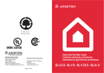
1
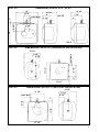
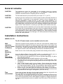
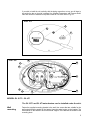
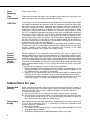
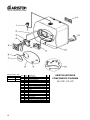
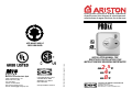
mini-tank electric water heaters
chauffe-eau électriques à miniréservoir
calentadores de agua eléctricos de minitanque
MTS MAKES USE OF
RECYCLED PAPER
Meets ASHRAE
90.1 standard
Merloni TermoSanitari SpA
Viale Aristide Merloni, 45
60044 Fabriano (AN)
Tel. 0732.6011
Telefax. 0732.602331
http://www.mtsgroup.com
E-mail: [email protected]
Controlled Energy Corp.
340 Mad River Park
Waitsfield, VT 05673
800-798-8161
www.protankless.com/tech
029.1.60.435.2.00 0604 Litograf s.r.l. Jesi
INSTALLATION MANUAL FOR
DIRECTIVES D’INSTALLATION POUR
INSTRUCCIONES DE SEGURIDAD IMPORTANTES
2.5Ti
GL4Ti
GL8Ti
GL
CONTROLLED ENERGY CORPORATION
340 Mad River Park
Waitsfield, Vermont 05673
800-798-8161 • www.Protankless.com
IMPORTANT SAFETY INSTRUCTIONS
WARNING
When using electrical appliances, safety precautions to reduce the risk of fire, electric
shock or injury to persons should be followed, including:
1.
2.
3.
4.
5.
6.
7.
8.
9.
READ ALL INSTRUCTIONS BEFORE USING THIS WATER HEATER.
This water heater must be grounded. Connect only to properly grounded outlet.
See “GROUNDING INSTRUCTIONS” found on “INSTALLATION INSTRUCTIONS”.
Install or locate this water heater only in accordance with the provided installation
instructions.
Use this water heater only for its intended use as described in this manual.
Do not use an extension cord set with this water heater. If no outlet is available
adjacent to the water heater, contact a qualified electrician to have one properly
installed.
As with any appliance, close supervision is necessary when used by children.
Do not operate this water heater if it is not working properly or if it has been
damaged or dropped.
This water heater should be serviced only by qualified service personnel. Contact
a service person for examination, repair or adjustment.
Failure to service the anode rod at least once a year could cause the tank to fail
and leak.
Any water heater should be installed in such a manner that if it should leak, the
resulting flow of water will not cause damage to the area in which it is installed.
National Plumbing codes require a drain pan for any water heater installation.
Failure to install one is the sole responsibility of owner and/or installer. Reference
UPC 2000 (Uniform Plumbing Code) Section 510 - Protection from Damage or
IPC 200 (International Plumbing Code) Section 504- Safety Devices.
KEEP THESE INSTRUCTIONS AT HAND
SAVE THESE INSTRUCTIONS
Technical data
MODEL
Capacity
gallons
Voltage
Vac
Power at 120 Vac
Watts
GL 4 Ti
GL 8 Ti
2.75
3.85
7.0
110/120 for each model
1500
1500
1500
Maximum Water pressure psi
150
150
150
Weight
Lbs
15.5
17.3
29.5
Amperage
Amps
Phases
WARNING
GL 2.5 Ti
12.50 for each model
1
1
1
The installer should review the contents of this manual with the owner upon
completion of installation, and the manual should be left with the owner and placed in
a location close to the installation.
1
FIG. 1/1
Temperature & pressure
relief valve, 3/4 NPT male
Hot water outlet
1/2 NPT male
Cold water inlet
1/2 NPT male
Temperature &
pressure relief
valve discharge
line to drain
3/4 NPT female
tapping for
relief valve
COMPONENT
PARTS OF
GL 2.5Ti - 4Ti
FIG. 1/2
Temperature & pressure
relief valve, 3/4 NPT male
COMPONENT PARTS OF GL 8Ti
(Horizontal installation)
Hot water outlet
3/4 NPT male
3/4 NPT male plug
3/4 NPT female
tapping for
relief valve
Temperature &
pressure relief
valve discharge
line to drain
Cold water inlet
3/4 NPT male
3/4 NPT female
tapping
FIG. 1/3
Hot water outlet
3/4 NPT male
3/4 NPT female
tapping for
relief valve
3/4 NPT male plug
3/4 NPT female
tapping
2
Temperature & pressure
relief valve, 3/4 NPT male
Cold water inlet
3/4 NPT male
COMPONENT
PARTS OF
GL 8Ti
(Vertical
installation)
Temperature &
pressure relief
valve discharge
line to drain
DIMENSIONS FOR GL 2.5Ti - GL 4Ti
FIG. 2/1
14”
10 1/4”
6”
3 3/4”
5 1/2”
1”
1/2 NPT MALE
12 1/4”
7 1/2”
GL 2.5
3 1/2”
3”
14”
2 1/2”
GL 4
FIG. 2/2
DIMENSIONS FOR GL 8Ti (HORIZONTAL INSTALLATION)
3”
17 1/2”
11 1/2”
3/4 NPT MALE
14 1/2”
8 1/2”
4 1/2”
17 1/2”
FIG. 2/3
DIMENSIONS FOR GL 8 Ti (VERTICAL INSTALLATION)
14 1/2”
8 1/2”
11 1/2”
3/4 NPT MALE
2 1/2”
17 1/2”
6 1/2”
1”
4 1/2”
17 1/2”
3
General remarks
CAUTION
The manufacturer cannot be responsible for the damages caused by improper
installation or by failure to follow instructions in this pamphlet. Comply with the
installation instructions before completing electric connection.
CAUTION
The thermostat has been pre-set at the factory at or below 51.7 °C (125° F).
CAUTION
Hydrogen gas can be produced in a hot water system served by this heater that has not
been used for a long period of time (generally 2 weeks or more). Hydrogen gas is
extremely flammable. To reduce the risk of injury under these conditions, it is
recommended that the hot water faucet be opened for several minutes before using any
electrical appliance connected to the hot water system. If hydrogen gas is present, there
will probably be an unusual sound such as air escaping through the pipe as the water
begins to flow. There should be no smoking or open flame near the faucet at this time.
CAUTION
Any water heater should be installed in such a manner that if it should leak, the resulting
flow of water will not cause damage to the area in which it is installed. National Plumbing
codes require a drain pan for any water heater installation. Failure to install one is the
sole responsibility of owner and/or installer. Reference UPC 2000 (Uniform Plumbing
Code) Section 510- Protection from Damage or IPC 2000 (International Plumbing Code)
Section 504- Safety Devices.
Installation instructions
MODEL GL 8Ti
The GL 8Ti water heater can be installed under the sink.
Wall
mounting
(only for vertical
installation)
Fasten the supplied mounting bracket to the wall. Use screws that are suitable for the
wall material and the weight of the heater. Hang the water heater on the bracket. Tug
down wards on the heater to ensure that both “fingers” of the bracket are seated in the
mounting slots. Confirm water piping orientation before wall mounting. Wall bracket will
not support the GL8Ti when the plumbing connections are installed horizontally.
Floor
Mounting
Heater can sit on floor. Confirm water piping orientation before locating on floor location.
Wiring
and
Grounding
instructions
As per the National Electric Code the GL8Ti needs to be wired with 12 GA. wire to a
minimum 20 amp/ maximum 20 amp branch circuit. To wire the GL8Ti model:
1. Pry off the round cover plate (V Fig. 3/1) from its right hand edge (W Fig. 3/1) with a
small flat-head screwdriver.
2. Remove the Phillips screw revealed beneath the round cover plate.
3. The cover (C Fig. 3/1) can now be removed by pulling out its left-hand edge. When
reassembling, work in the opposite way being careful to insert the tongue of the cover
into the slot.
4. Insert 12 AWG through conduit at rear of heater. Secure internal wire connector
(A Fig. 3/2) and connect wiring to right side of thermostat control and ground. Positive
(+) to lower terminal marked “L” (E Fig. 3/2) and Neutral to upper terminal marked “N”
(H Fig. 3/2). Unit must be grounded at groundscrew (T Fig. 3/2) on element base.
5. When the GL8Ti is not within sight of the electrical circuit breakers, a circuit breaker
lockout or additional local means of disconnection for all non grounded conductors must
be provided that is within sight of the appliance. [REF NEC 422.31]
Pipe
connections
Connect the cold water inlet pipe to the inlet nipple (marked with a blue ring) and the hot
water outlet pipe to the outlet nipple (marked with a red ring).
The model GL8Ti can be piped horizontally from the side or vertically from the top. If you
wish to install the unit horizontally, with the piping connections on the right side, you will have
to be certain the tap between the two water tappings is plugged, the supplied Temperature
and Pressure Relief Valve will need to be installed on top. See location of T&P relief valve in
Fig. 2/2.
4
If you wish to install the unit vertically, with the piping connections on top, you will have to
be certain the tap on the side is plugged, the supplied Temperature and Pressure Relief
Valve will need to be installed on top. See location of T&P relief valve in Fig. 2/3.
FIG. 3/1
C
V
W
F
G
FIG. 3/2
H
Z
F
E
X
Y
T
A
MODEL GL 2.5Ti - GL 4Ti
The GL 2.5Ti and GL 4Ti water heaters can be installed under the sink.
Wall
mounting
Fasten the supplied mounting bracket to the wall. Use screws that are suitable for the
wall material and the weight of the heater. Hang the water heater on the bracket. Tug
down wards on the heater to ensure that both “fingers” of the bracket are seated in the
mounting slots.
5
Floor
Mounting
Heater can sit on floor.
Pipe
connections
Connect the cold water inlet pipe to the inlet nipple (marked with a blue ring) and the hot
water outlet pipe to the outlet nipple (marked with a red ring).
CAUTION
To reduce the risk of excessive pressures and temperatures in this water heater, install
the supplied temperature and pressure protective equipment required by local codes
but not less than a combination temperature and pressure relief valve certified by a
nationally recognized testing laboratory that maintains periodic inspection of
production of listed equipment or materials, as meeting the requirements for Relief
Valves and Automatic Gas Shut-off Devices for Hot Water Supply Systems, ANSI
Z21.22. The supplied temperature and pressure relief valve is marked with a maximum
set pressure (150 psi) that does not exceed the marked maximum working pressure
of the water heater. Install the valve in the opening provided and marked for this
purpose in the water heater, and orient it or provide tubing so that any discharge from
the valve will exit within 6 inches above, or at any distance below, the structural floor,
and cannot contact any live electrical part. The discharge opening must not be blocked
or reduced in size under any circumstances.
National Plumbing codes require a drain pan for any water heater installation. Failure
to install one is the sole responsibility of owner and/or installer. Reference UPC 2000
(Uniform Plumbing Code) Section 510- Protection from Damage or IPC 2000
(International Plumbing Code) Section 504- Safety Devices.
Closed
system
thermal
expansion
(for all
models)
Periodic discharge of the temperature and pressure relief valve or failure of the
element gasket may be due to thermal expansion in a closed water supply system.
The water utility supply meter may contain a check valve, backflow preventer or water
pressure reducing valve which will create a closed water system. During the heating
cycle of the water heater, the water expands causing pressure inside the water heater
to increase. The temperature and pressure relief valve may discharge hot water under
these conditions which results in a loss of energy and a build-up of lime on the relief
valve seat.
To prevent this from happening, there are two recommendations:
1. Install a diaphragm-type expansion tank that is suitable for potable water on the
cold water supply line. The expansion tank must have a minimum capacity of 1.5
U.S. gallons for every 50 gallons of stored water.
2. Install a 125 PSI pressure relief valve in the cold water supply line. Make sure the
discharge of this valve is directed to an open drain and protected from freezing.
Contact the local water supplier or plumbing inspector for information on how to
control this situation. Do not plug the temperature and pressure relief valve.
Instructions for use
Starting and
testing
Before connecting the power, fill the tank and system with water and check for leaks. To
be certain that all air is out of the water system, open the hot water faucets on your fixtures
until constant water flows from them, otherwise damage to the element may occur.
To start the heating cycle:
A) first make sure tank is full. Otherwise the heating element may be damaged.
B) the red light will come on and remain on until that temperature has been reached,
at which point the light will go off, but will automatically come back on when the
water temperature drops below the setting chosen.
Temperature
Setting
After installation check the water temperature. If adjustment is necessary, remove front
cover to adjust thermostat (D Fig. 4 -clockwise to increase the temperature and
counter clockwise to decrease it).
To reach the thermostat:
1. Pry off the round cover plate (V Fig. 3/1) from its right hand edge (W Fig. 3/1) with
a small flat-head screwdriver.
2. Remove the Phillips screw revealed beneath the round cover plate.
6
3.
The cover (C Fig. 3/1) can now be removed by pulling out its left-hand edge.
When reassembling, work in the opposite way being careful to insert the tongue
of the cover into the slot.
FIG. 4
B
D
Maintenance instructions
Note: Do not attempt to repair this water heater yourself. Call a service person
for assistance. Always turn off the power supply to the heater prior to
servicing or draining the heater.
Periodic maintenance
Note: For most of these operations, the water will have to be drained from the heater.
For all of these operations the power supply needs to be shut off and the front
cover removed.
1. Pry off the round cover plate (V Fig. 3/1) from its right hand edge (W
Fig. 3/1) with a small flat-head screwdriver.
2. Remove the Phillips screw revealed beneath the round cover plate.
3. The cover (C Fig. 3/1) can now be removed by pulling out its left-hand
edge. When reassembling, work in the opposite way being careful to
insert the tongue of the cover into the slot.
Draining
the Heater
1) If the heater has been installed with flexible hoses, shut off the power supply and
turn the heater upside down over a sink to drain the water out of it, OR
2) If the heater has been installed with rigid piping, siphon the water out through any
(lower) service valve on the (inlet side). Keep a hot water faucet open while
siphoning the water out, OR
3) If the heater has been installed with flexible hoses, it can also be emptied by
siphoning through the inlet side hose. Keep a hot water faucet open while
siphoning.
7
Removing
the heating
element
1. Turn off power supply and drain the heater (see previous section).
2. Remove the front cover plate, disconnect terminals X, Y and T (fig. 3/2).
3. Unscrew the 4 heating element retaining nuts F (fig. 3/2).
4. Remove the element. G (fig. 5/1).
FIG. 5/1
N
G
FIG. 5/2
Descaling
the heating
element
Scale deposits can affect the heating capability of the element.
Heavy scale can even cause the element to burn out. The element can be descaled
either chemically or manually:
A) Soak the element in white vinegar or other descaling solution. Once descaled,
rinse well with fresh water, to which you should add some baking soda, OR
B) Once the element has dried up, use a soft brush (non metallic to prevent damaging
the stainless steel sheath) on element. Brush the dried mineral off. Reinstall the
element with gasket and make the wire connections.
C) Replace anode rod (N Fig. 5/2) if it is noticeably deteriorated or considerably
shorter then seen in figure 5/2.
WARNING: make sure the tank has been refilled with water before restoring power.
REPLACEMENT OF PARTS
Changing
the anode
rod
The anode rod (N fig. 5/2) helps protect the tank against corrosion. Depending on the
water condition, the magnesium anode rod may need to be changed every year or so.
Galvanic and electrolytic corrosion can destroy a tank if the anode rod is “spent”.
Rusty water is usually an indication of a “spent” anode rod. If rusty water is present,
examine anode rod immediately. Rapid degradation of the anode rod (less than 1
year) may indicate the presence of galvanic corrosion due to “stray” direct current. In
this case, it may be necessary to add a “grounding strap” from the Ariston tank to the
copper plumbing.
1. Turn off the power supply and drain the heater (see Draining the Heater).
2. Remove heating element (see previous section).
3. Remove and replace the anode rod N Fig. 5/2.
4. Refill tank with water before restoring power.
8
Changing
the heating
element
1. Turn off power supply and drain the heater (see Draining the Heater).
2. Remove the heating element (see section on Removing the Heating Element).
3. Install new element with gasket, making sure the gasket and element are positioned
correctly. Tighten the retaining nuts and make the wire connections.
4. Refill tank with water before restoring power.
Changing
the
thermostat
1. Turn off power supply.
2. Disconnect the 2 push/pull type wires on thermostat.
3. Loosen the two brass screws at right side of thermostat and pull wires out.
4. Unscrew and remove the two phillips screws holding the thermostat down.
5. Install new thermostat and re-attach wiring and screws.
Resetting
High Limit
Switch
Occasionally, the high temperature limit shut off device may trigger and shut the
system down. This occurs when water temperature exceeds 190° F and shuts off
power to the heating element. The shut off device may also trigger from a power
outage or electrical storm.
To reach the thermostat:
1. Pry off the round cover plate (V Fig. 3/1) from its right hand edge (W Fig. 3/1) with
a small flat-head screwdriver.
2. Remove the Phillips screw revealed beneath the round cover plate.
3. The cover (C Fig. 3/1) can now be removed by pulling out its left-hand edge. When
reassembling, work in the opposite way being careful to insert the tongue of the
cover into the slot.
4. Firmly press reset button (B Fig. 4). Reconnect power.
5. IMPORTANT: Check the operation of the thermostat, turn temperature dial from
high to low, if the red light does not go off on low setting, turn off power supply and
call a service person to replace the thermostat.
6. If the system works, place dial setting to desired setting. Note: a lower setting is
more economical and reduces the risk of scalding. Replace cover plate.
CAUTION: Call a technician if the high limit needs to be reset frequently.
Troubleshooting
Water does
not get hot
1. Make sure the power supply is on and working.
2. If light does not come on, check that the reset button is pushed in; follow steps from
previous section.
3. If the indicator light works properly but temperature does not get hot a tap, test for
a plumbing crossover; shut off cold supply to heater and open hot water tap. There
should be no water flowing. Any continued flow indicates a crossover which will
effect the temperature and will need to be corrected.
4. Replace heating element (see previous section on changing the heating element).
Light not on
1. If the light does not come on, but water gets hot, check for faulty bulb.
2. Check reset button; follow steps from previous section.
Brown water
1. Brown or rusty water indicates a “spent” anode rod. Replace anode rod.
Odor in water
1. Smelly water could be due to an unusual reaction between local water and the
heater’s anode rod. Check anode rod (see section on changing the anode rod).
Water is too
hot
1. Remove cover plate and turn the temperature selector dial (D Fig. 4) counter
clockwise to lower temperature. If temperature never lowers then replace
thermostat. (see section on changing the thermostat).
Water not
hot enough
1. Adjust the temperature selector dial (D Fig. 4) clockwise to increase temperature.
Leaking
1. Check water fittings and T & P fitting on top of tank.
2. Remove front cover and inspect heating element gasket.
9
DESCRIPTION REF.
GL 2.5Ti
GL 4Ti
GL 8Ti
10
A
B
C
PART
1
2
2
3
4
5
5
6
7
8
9
10
11
11
12
13
14
15
CODE
100XL
570241
574305
994147
994140
994103
994104
DESCRIPTION
VALVE (T&P 3/4”)
ANODE (MAGNESIUM)
ANODE (MAGNESIUM)
GASKET WITH 4 BOLTS
LOCK NUT M6
HEATING ELEMENT (1500/120)
HEATING ELEMENT (1500/120)
PLASTIC COVER RETAINING SCREW
NAME BADGE (PLASTIC)
COVER
SWITCH COVER
THERMOSTAT WIRING
994062 THERMOSTAT
994102 THERMOSTAT
CABLE CLAMP
SUPPLY CABLE
570341 HEATER WALL HANGING BRACKET
gl6plug 3/4” BRASS PLUG (GL6 ONLY)
REF.
ABC
C
AB
ABC
ABC
AB
C
AB
C
AB
ABC
C
ARISTON INTERIOR
COMPONENTS DIAGRAM
GL 2.5Ti, 4Ti, 8Ti
ARISTON GLTi • LIMITED 8 YEARS WARRANTY
COVERAGE
ARISTON, THROUGH ITS U.S. DISTRIBUTOR
CONTROLLED ENERGY CORP., (hereinafter
CEC) guarantees this water heater to the
Owner (hereinafter “Owner”) of the water heater
at the original installation location against
defects in material and workmanship for the
periods specified below.
WARRANTY PERIOD
1. The inner Tank - If the inner tank leaks within
eight (8) years from the date of original
installation of the water heater, because of a
defect in material or workmanship, CEC will
furnish to such Owner a new heater of the then
prevailing comparable model.
2. Any Component Part Other than The
Original Inner Tank - If any component part
(other than the inner tank) proven to be
defective in material or workmanship within one
(1) year from the date of original installation of
the water heater, CEC will furnish the Owner
with a replacement of the defective part(s).
3. Verification of Date of Original Installation
- When Owner cannot verify or document the
original date of installation, the warranty period
begins on the date of manufacture marked on
the tag affixed to the water heater.
EXCLUSIONS
1. THIS LIMITED WARRANTY SHALL BE THE
EXCLUSIVE WARRANTY MADE BY THE
MANUFACTURER AND IS MADE IN LIEU OF
ALL OTHER WARRANTIES, EXPRESSED OR
IMPLIED (WHETHER WRITTEN OR ORAL),
INCLUDING,
BUT NOT LIMITED TO,
WARRANTIES OF MERCHANTABILITY AND
FITNESS FOR A PARTICULAR PURPOSE.
2. The Manufacturer shall not be liable for any
incidental, consequential, special or contingent
damages or expenses arising, directly or
indirectly, from any defect in the water heater or
the use of the water heater.
supplied with potable water.
5. The OWNER and not the Manufacturer or his
representative shall be liable for and shall pay
for all field charges for labor or other expenses
incurred in the removal and/or repair of the
product or any expense incurred by the owner
in order to repair the product.
SOME STATES DO NOT ALLOW THE
EXCLUSION OR LIMITATION OF INCIDENTAL
OR CONSEQUENTIAL DAMAGES, SO THE
ABOVE LIMITATION OR EXCLUSION MAY
NOT APPLY TO YOU. THIS WARRANTY
GIVES YOU SPECIFIC LEGAL RIGHTS AND
YOU MAY ALSO HAVE OTHER RIGHTS
WHICH MAY VARY FROM STATE TO STATE.
IMPORTANT: OWNER SHALL KEEP THIS
MAKE A CLAIM
NOTE: A water heater should be installed in
such a manner that if it should leak, the
resulting flow of water will not cause damage
to the area in which it is installed.
HOW THE OWNER CAN SECURE SERVICE
OR MAKE A CLAIM
1. Owner should contact the dealer who sold
the water heater covered by this warranty or
2. Owner should submit the warranty claim
directly to CEC at the address listed below, and
they will arrange for the handling of the claim
3. Whenever any inquiry or service request is
made, be sure to include the water heater
model number the date of manufacture , date of
installation, Dealer’s name and the watts and
voltage.
4. When returning the water heater or
component part(s), they must be individually
tagged and identified with the Returned Goods
Authorization # issued by CEC and shipped
prepaid to CEC at the address below.
3. The Manufacturer shall not be liable for any
water damage arising, directly or indirectly, from
any defect in the water heater component
part(s) or from its use.
4. Manufacturer shall not be liable under this
warranty if:
a) The water heater or any of its component
parts has been subject to misuse, alteration,
neglect or accident, or
b) The water heater has not been installed in
accordance with the applicable local
plumbing and/or building code(s) and/or
regulation(s), or
c) The water heater has not been installed in
accordance with the printed manufacturer’s
instructions, or
d) The water heater is not continuously
Controlled Energy Corp.
340 Mad River Park
Waitsfield, VT 05673
800-798-8161
www.protankless.com/tech
mini-tank electric water heaters
chauffe-eau électriques à miniréservoir
calentadores de agua eléctricos de minitanque
MTS MAKES USE OF
RECYCLED PAPER
Meets ASHRAE
90.1 standard
Merloni TermoSanitari SpA
Viale Aristide Merloni, 45
60044 Fabriano (AN)
Tel. 0732.6011
Telefax. 0732.602331
http://www.mtsgroup.com
E-mail: [email protected]
Controlled Energy Corp.
340 Mad River Park
Waitsfield, VT 05673
800-798-8161
www.protankless.com/tech
029.1.60.435.2.00 0604 Litograf s.r.l. Jesi
INSTALLATION MANUAL FOR
DIRECTIVES D’INSTALLATION POUR
INSTRUCCIONES DE SEGURIDAD IMPORTANTES
2.5Ti
GL4Ti
GL8Ti
GL
CONTROLLED ENERGY CORPORATION
340 Mad River Park
Waitsfield, Vermont 05673
800-798-8161 • www.Protankless.com