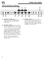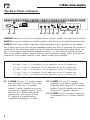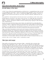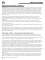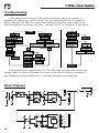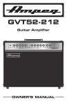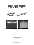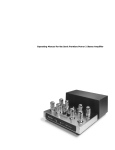
1
V-4B
Bass Guitar Amplifier
+
0
ULTRA LO
1
220 HZ
2
8OO HZ
3
3OOO HZ
+
0
ULTRA HI
SS
EQUALIZATION
TDSK
CUT
0 dB
-15 dB
GAIN
BASS
MODEL
V-4B
BOOST
MIDRANGE
TREBLE
MASTER
Owner’s Manual
STANDBY
POWER
V-4B Bass Guitar Amplifier
TABLE OF CONTENTS
Important Safety Instructions..................................................2
Introduction / Features...........................................................4
The Front Panel.....................................................................5
The Rear Panel......................................................................7
Important Information About Tubes..........................................9
Troubleshooting / Block Diagram..........................................14
Technical Specifications / Service Information........................15
been spilled or objects have fallen into the IMPORTANT SAFETY INSTRUCTIONS
apparatus, the apparatus has been exposed to
rain or moisture, does not operate normally, or
has been dropped.
1. Read these instructions. 2. Keep these instructions.
3. Heed all warnings.
4. Follow all instructions.
5. Do not use this apparatus near water.
6. Clean only with a dry cloth.
7. Do not block any ventilation openings. Install in
accordance with the manufacturer’s instructions.
8. Do not install near any heat sources such as
radiators, heat registers, stoves, or other apparatus (including amplifiers) that produce heat.
9. Do not defeat the safety purpose of the polarized or grounding-type plug. A polarized plug
has two blades with one wider than the other. A
grounding-type plug has two blades and a third
grounding prong. The wide blade or the third
prong are provided for your safety. If the provided
plug does not fit into your outlet, consult an electrician for replacement of the obsolete outlet.
10. Protect the power cord from being walked
on or pinched particularly at plugs, convenience
receptacles, and the point where they exit from
the apparatus.
11. Only use attachments/accessories specified
by the manufacturer.
12. Use only with a cart, stand,
tripod, bracket, or table specified
by the manufacturer, or sold with
the apparatus. When a cart is used,
use caution when moving the cart/
apparatus combination to avoid
injury from tip-over.
PORTABLE CART
WARNING
13. Unplug this apparatus during lightning storms
or when unused for long periods of time.
14. Refer all servicing to qualified service personnel. Servicing is required when the apparatus has been damaged in any way, such as
power-supply cord or plug is damaged, liquid has
2
15. Do not overload wall outlets and extension
cords as this can result in a risk of fire or electric
shock.
16. This apparatus shall not be exposed to dripping or splashing, and no object filled with
liquids, such as vases or beer glasses, shall be
placed on the apparatus.
17. This apparatus has been designed with Class-I
construction and must be connected to a mains
socket outlet with a protective earthing connection
(the third grounding prong).
18. The MAINS plug or an appliance coupler is
used as the disconnect device, so the disconnect
device shall remain readily operable.
19. For the terminals marked with symbol of “ ”
may be of sufficient magnitude to constitute a risk
of electric shock. The external wiring connected to the terminals requires installation by
an instructed person or the used of ready-made
leads or cords.
CAUTION
AVIS
RISK OF ELECTRIC SHOCK. DO NOT OPEN
RISQUE DE CHOC ELECTRIQUE. NE PAS OUVRIR
CAUTION: TO REDUCE THE RISK OF ELECTRIC SHOCK DO NOT REMOVE COVER (OR BACK)
NO USER-SERVICEABLE PARTS INSIDE. REFER SERVICING TO QUALIFIED PERSONNEL
ATTENTION: POUR EVITER LES RISQUES DE CHOC ELECTRIQUE, NE PAS ENLEVER LE COUVERCLE.
AUCUN ENTRETIEN DE PIECES INTERIEURES PAR L'USAGER.
CONFIER L'ENTRETIEN AU PERSONNEL QUALIFIE.
AVIS: POUR EVITER LES RISQUES D'INCENDIE OU D'ELECTROCUTION, N'EXPOSEZ PAS CET ARTICLE
A LA PLUIE OU A L'HUMIDITE
The lightning flash with arrowhead symbol within an equilateral triangle is
intended to alert the user to the presence of uninsulated "dangerous
voltage" within the product's enclosure, that may be of sufficient magnitude
to constitute a risk of electric shock to persons.
Le symbole éclair avec point de flèche à l'intérieur d'un triangle équilatéral
est utilisé pour alerter l'utilisateur de la présence à l'intérieur du coffret de
"voltage dangereux" non isolé d'ampleur suffisante pour constituer un risque
d'éléctrocution.
The exclamation point within an equilateral triangle is intended to alert the
user of the presence of important operating and maintenance (servicing)
instructions in the literature accompanying the appliance.
Le point d'exclamation à l'intérieur d'un triangle équilatéral est employé
pour alerter les utilisateurs de la présence d'instructions importantes pour le
fonctionnement et l'entretien (service) dans le livret d'instruction
accompagnant l'appareil.
Laite on liitettävä suojakoskettimilla varustettuun pistorasiaan.
Apparatet må tilkoples jordet stikkontakt.
Apparaten skall anslutas till jordat uttag.
V-4B Bass Guitar Amplifier
NOTE: This equipment has been tested and found to comply
with the limits for a Class B digital device, pursuant to part 15 of
the FCC Rules. These limits are designed to provide reasonable
protection against harmful interference in a residential installation.
This equipment generates, uses, and can radiate radio frequency
energy and, if not installed and used in accordance with the instructions, may cause harmful interference to radio communications. However, there is no guarantee that interference
will not occur in a particular installation. If this equipment does
cause harmful interference to radio or television reception, which
can be determined by turning the equipment off and on, the user
is encouraged to try to correct the interference by one or more of
the following measures:
ATTENTION — Le présent appareil numérique n’émet pas de
bruits radioélectriques dépassant las limites applicables aux appareils numériques de class A/de class B (selon le cas) prescrites dans le réglement sur le brouillage radioélectrique édicté
par les ministere des communications du Canada.
•
Reorient or relocate the receiving antenna.
•
Increase the separation between the equipment and the
receiver.
•
Connect the equipment into an outlet on a circuit different
from that to which the receiver is connected.
•
Consult the dealer or an experienced radio/TV technician for
help.
According to OSHA, any exposure in excess of these permissible limits could result in some hearing loss. To ensure
against potentially dangerous exposure to high sound pressure
levels, it is recommended that all persons exposed to equipment
capable of producing high sound pressure levels use hearing protectors while the equipment is in operation. Ear plugs or protectors in the ear canals or over the ears must be worn when
operating the equipment in order to prevent permanent hearing
loss if exposure is in excess of the limits set forth here:
CAUTION: Changes or modifications to this device not expressly
approved by LOUD Technologies Inc. could void the user's authority
to operate the equipment under FCC rules.
This apparatus does not exceed the Class A/Class B (whichever
is applicable) limits for radio noise emissions from digital apparatus as set out in the radio interference regulations of the
Canadian Department of Communications.
NOTE — This amplifier is intended for professional use only.
Exposure to extremely high noise levels may cause permanent
hearing loss. Individuals vary considerably in susceptibility to noise-induced hearing loss, but nearly everyone will lose some
hearing if exposed to sufficiently intense noise for a period of
time. The U.S. Government’s Occupational Safety and Health
Administration (OSHA) has specified the permissible noise level
exposures shown in the following chart.
Duration, per
day in hours
8
6
4
3
2
1.5
1
Sound
Level dBA, Slow
Response
90
92
95
97
100
102
105
0.5
0.25 or less
110
115
Typical Example
Duo in small club
Subway Train
Very loud classical music
The boss screaming at his minions about
manual deadlines
Loudest parts at a rock concert
CONSIGNES DE SECURITE IMPORTANTES
- LIRE, SUIVRE TOUTES LES INSTRUCTIONS ET LES PRECAUTIONS D’UTILISATION
- NE PAS UTILISER PROCHE D’UNE SOURCE DE CHALEUR ET NE PAS BLOQUER OU OBSTRUER LE SYSTEME DE VENTILATION SUR CET APPAREIL. POUR UNE
UTILISATION CONFORME, CET APPAREIL NECESSITE ENVIRON 7CM D’ESPACE BIEN VENTILE AUTOUR DE SON SYSTEME DE REFROIDISSEMENT, AINSI QU’UN COURANT
D’AIR FRAIS CONSTANT
- NE PAS UTILISER CET APPAREIL PROCHE D’UNE SOURCE LIQUIDE
- NETTOYER SEULEMENT A L’AIDE D’UN CHIFFON DOUX ET SEC ET NE PAS UTILISER DE PRODUITS MENAGERS
- CONNECTER UNIQUEMENT LE CABLE D’ALIMENTATION FOURNI SUR UNE PRISE AVEC MISE A LA TERRE, ET COMPATIBLE AVEC LA TENSION, L’INTENSITE ET LA
FREQUENCE REQUISES INDIQUEES SUR LA FACE ARRIERE DE L’APPAREIL
- S’ASSURER DE NE PAS MARCHER, PLIER OU TIRER SUR LE CABLE D’ALIMENTATION
- DEBRANCHER L’APPAREIL LORS D’UNE TEMPETE OU LORS D’UNE TRES LONGUE PERIODE DE NON UTILISATION
- UTILISER UNIQUEMENT DES ACCESSOIRES SPECIFIES PAR LE FABRICANT POUR UNE UTILISATION EN TOUTE SECURITE ET POUR EVITER DES BLESSURES
- ATTENTION: AFIN DE PREVENIR TOUT RISQUE DE CHOCS ELECTRIQUES OU DE DEBUT D’INCENDIE, NE PAS EXPOSER CET APPAREIL A LA PLUIE ET A L’HUMIDITE
- TOUT ENTRETIEN DOIT ETRE FAIT PAR UN TECHNICIEN QUALIFIE
- NOS AMPLIFICATEURS PEUVENT PRODUIRE DE TRES HAUTES PRESSIONS ACOUSTIQUES QUI PEUVENT CAUSER DES DOMMAGES AUDITIFS PERMANENTS OU
DEFINITIFS. L’UTILISER AVEC UNE GRANDE PRECAUTION EST CONSEILLE ET DES PROTECTIONS AUDITIVES SONT RECOMMANDEES POUR UNE UTILISATION A FORT
VOLUME.
- ATTENTION: CET APPAREIL REQUIERT UNE PRISE MURALE AVEC MISE A LA TERRE, AUX NORMES ACTUELLES ET COMPATIBLE AVEC LES SPECIFICATIONS
ELECTRIQUES SE TROUVANT EN FACE ARRIERE DE L’APPAREIL. LA PRISE ELECTRIQUE DOIT RESTER ACCESSIBLE POUR DEBRANCHER L’APPAREIL EN CAS DE DEFAUT
PENDANT L’UTILISATION
- CET APPAREIL DOIT ETRE DEBRANCHE SI IL N’EST PAS UTILISE
Elimination correcte du produit : Ce symbole indique que ce produit ne doit pas être éliminé avec les ordures ménagères, comme le prévoiT la directive WEEE (2002/96/
EC) et votre loi nationale.
Ce produit doit être remis à un site de recyclage des déchets électriques et des équipements électroniques (EEE).
Un mauvais recyclage de ce type de déchet peut avoir de possibles impacts négatifs sur l’environnement et la santé humaine dus aux émanations de substances.
Dans un même temps, votre coopération à un recyclage correct de ce produit contribuera à la bonne utilisation des ressources naturelles.
Pour connaître l’endroit où il est possible de recycler ces équipements, merci de contacter votre mairie, les services de recyclages ou le service des déchets ménagers.
Correct disposal of this product: This symbol indicates that this product should not be disposed of with your household waste,
according to the WEEE directive (2002/96/EC) and your national law. This product should be handed over to an authorized collection site for recycling waste electrical and electronic equipment (EEE). Improper handling of this type of waste could have a
possible negative impact on the environment and human health due to potentially hazardous substances that are generally associated with EEE. At the same time, your cooperation in the correct disposal of this product will contribute to the effective usage
of natural resources. For more information about where you can drop off your waste equipment for recycling, please contact your
local city office, waste authority, or your household waste disposal service.
3
V-4B Bass Guitar Amplifier
Introduction
Congratulations on your purchase of the Ampeg V-4B 100W all-tube bass head.
Based on the original from 1971, the Ampeg V-4B 100W all-tube head embodies the
legendary tone of the classic V-4B in a tough-as-nails package, ready to take the stage
with the flexible output control and pure vintage Ampeg grind you crave at volume levels
ideal for modern venues and applications.
With a built-in suspension system, metal chassis, and 15 mm birch cabinet enclosure,
the V-4B will go anywhere your tone needs to.
Best of luck in all of your musical endeavors!
Sincerely,
The dedicated team at Ampeg
Features
• RMS power output: 100W
• Chassis Suspension System
• Preamp tube: 2 x 12AX7
• Driver tube: 1 x 12AX7, 1 x 12AU7
• Power amp tube: 4 x 6L6GC
• Tone controls: Bass, mid, treble (3-position midrange rocker, ultra hi / ultra lo)
• Balanced direct out
• –15 dB input
• Dimensions (H x W x D) 10.8" x 23.8" x 11"
• Handling weight: 41 lb [18.6 kg]
Like us
Follow us
Watch our dang videos
4
V-4B Bass Guitar Amplifier
The Front Panel
4
+
0
ULTRA LO
5
1
220 HZ
6
2
800 HZ
3
3OOO HZ
11
+
0
ULTRA HI
EQUALIZATION
MODEL
V-4B
CUT
BOOST
0 dB
-15 dB
GAIN
BASS
MIDRANGE
TREBLE
MASTER
STANDBY
POWER
1
2
3
7
8
9
10
12
13
1. 0 dB INPUT: The signal output from a
passive instrument may be connected to
this 1/4" input by means of a shielded
instrument cable.
2. -15 dB INPUT: The signal output from
an active instrument may be connected
to this 1/4" input by means of a shielded
instrument cable.
3.GAIN: This control adjusts the basic
level of signal in the preamp.
4. ULTRA LO: This switch, when engaged
[right side down], enhances the amount
of low frequency output by 2 dB at
40 Hz and -11 dB cut at 500 Hz.
5. 1•2•3 SWITCH: This switch selects
the frequency that will be affected by
the midrange control [8]. The available
frequencies are:
Left = 220 Hz
Center = 800 Hz
Right = 3 kHz
6. ULTRA HI: This switch, when engaged
[right side down], enhances the amount
of high frequency output by 7 dB at
8 kHz.
7.BASS: Use this to adjust the low frequency level of the amplifier. This provides up to 13 dB of boost, or 12 dB of cut at 40 Hz. The low frequency output is flat at the center
position.
8.MIDRANGE: Use this to adjust the midrange frequency level of the amplifier. This provides up to 11 dB of
boost, or 21 dB of cut at the selected
frequency [5]. The midrange frequency output is flat at the center position.
Rotate the control counter-clockwise
for a “contoured” sound (more distant,
less midrange output) or clockwise for a
sound which really cuts through.
9.TREBLE: Use this to adjust the high frequency level of the amplifier. This
provides up to 14 dB of boost, or 17 dB of cut at 4 kHz. The high frequency output is flat at the center
position.
10.MASTER: Use this to control the overall output level. It affects the speaker outputs and the preamp
output [16]. Use it wisely, and turn
it down when making connections
or trying something new.
5
V-4B Bass Guitar Amplifier
The Front Panel continued...
4
+
0
ULTRA LO
5
1
220 HZ
6
2
800 HZ
3
3OOO HZ
11
+
0
ULTRA HI
EQUALIZATION
MODEL
V-4B
CUT
0 dB
-15 dB
GAIN
BASS
MIDRANGE
TREBLE
MASTER
STANDBY
POWER
1
2
3
7
8
9
10
12
13
11. STANDBY/POWER LED: This is a
multi-function LED. In Standby mode,
it glows red and in the On mode it
glows green.
12. STANDBY SWITCH: Use this switch to
turn the standby power on or off. Press
the top of the switch to turn the standby
on. The standby mode allows the tubes
to warm or remain warm without high
voltage being applied to them. This
extends tube life. This switch should be
OFF when first turning the amplifier on.
Allow the unit to warm up for at least
60 seconds before switching to the ON
position. During short periods of non-use, the amp should be put into
standby mode.
6
BOOST
13. POWER SWITCH: Use this switch to
turn the overall system power on or off.
Press the top of the switch to turn on
the power. The power switch should be
engaged prior to the standby switch (as
mentioned to the left, #12).
V-4B Bass Guitar Amplifier
The Rear Panel
TUBE
COMPLEMENT:
MODEL
V-4B
POWER CONSUMPTION 100W
POWERAMP 6L6
PREAMP
6L6
6L6
12AX7
CAUTION
RISK OF ELECTRICAL SHOCK
DO NOT OPEN
FUSE:
FOR 100V-120V
FOR 220V-240V
:T4A H 250V
:T2A H 250V
AVIS: RISQUE DE CHOC ELECTRIQUE
NE PAS OUVRIR.
12AU7
6L6
12AX7
BALANCED
OUT
PREAMP
OUT
POWER AMP
IN
WARNING: TO REDUCE THE RISK OF FIRE OR ELECTRIC SHOCK, DO NOT EXPOSE
SLAVE
OUT
12AX7
SPEAKERS-100W @ SELECTED IMPEDANCE - CLASS 2 WIRING
LIFT
2 OHMS
2 OHMS
4 OHMS
4 OHMS
8 OHMS
GND
THIS EQUIPMENT TO RAIN OR MOISTURE. DO NOT REMOVE COVER. NO USER
SERVICEABLE PARTS INSIDE. REFER SERVICING TO QUALIFIED PERSONNEL.
AVIS: N'OUVREZ PAS LA COUVERTURE. N'EXPOSEZ PAS CET ÉQUIPEMENT À
LA PLUIE OU À L'HUMIDITÉ.
AC LINE IN
CAUTION: TO REDUCE THE
RISK OF FIRE, REPLACE FUSE WITH
THE SAME TYPE AND RATING.
14
ATTENTION: UTILISER UN
FUSIBLE DE RECHANGE DE MEME
TYPE.
15
16 17 18 19 20
14. AC LINE IN: This is where you connect
the supplied AC power cord. Plug the
male end of the cord into a grounded
AC outlet.
DO NOT DEFEAT THE GROUND PRONG
OF THE AC PLUG!
15.FUSE: This protects the unit from damage due to overload conditions or
power line surges. If the fuse blows,
replace it only with the same size and
type.
16. PREAMP OUT: This jack is a direct
post master preamp output for use with
an external power amp. Connect the
external amp’s input to this jack using a
shielded instrument cable.
17. POWER AMP IN: This jack connects
directly to the internal power amp for
use with an external preamp. When
using an external source, connect the
OUTPUT of the source to this jack using
a shielded instrument cable to feed the
signal into the power amp section. The
internal signal is disconnected when a
plug is inserted into this jack.
USE WITH ONE 2 OHM CABINET
OR TWO 4 OHM CABINETS
USE WITH ONE 4 OHM CABINET
OR TWO 8 OHM CABINETS
21
22
23
18. SLAVE OUT: This jack receives the
same signal that is being sent to the
power amp. It is useful for powering
another amp (slave) from this unit’s preamp.
19. BALANCED OUT: This XLR jack is the
output at the power amp in. Thus, it
will include any processing done in the
Preamp Out/Power Amp In loop. This
signal may be used to feed an external
power amplifier, mixing console or house
PA system.
The lift / gnd switch [20] is available
to reduce any noise that may occur
at the balanced output.
20. LIFT / GND: When this switch is
engaged, it connects the ground
connection at the balanced output
jack [19]. This may help reduce
residual hum and buzz sometimes
picked up in line out signal cables.
7
V-4B Bass Guitar Amplifier
The Rear Panel continued...
TUBE
COMPLEMENT:
MODEL
V-4B
POWER CONSUMPTION 100W
POWERAMP 6L6
PREAMP
6L6
6L6
12AX7
CAUTION
RISK OF ELECTRICAL SHOCK
DO NOT OPEN
FUSE:
FOR 100V-120V
FOR 220V-240V
:T4A H 250V
:T2A H 250V
AVIS: RISQUE DE CHOC ELECTRIQUE
NE PAS OUVRIR.
12AU7
6L6
12AX7
BALANCED
OUT
PREAMP
OUT
WARNING: TO REDUCE THE RISK OF FIRE OR ELECTRIC SHOCK, DO NOT EXPOSE
POWER AMP
IN
SLAVE
OUT
12AX7
SPEAKERS-100W @ SELECTED IMPEDANCE - CLASS 2 WIRING
LIFT
2 OHMS
2 OHMS
4 OHMS
4 OHMS
8 OHMS
GND
THIS EQUIPMENT TO RAIN OR MOISTURE. DO NOT REMOVE COVER. NO USER
SERVICEABLE PARTS INSIDE. REFER SERVICING TO QUALIFIED PERSONNEL.
AVIS: N'OUVREZ PAS LA COUVERTURE. N'EXPOSEZ PAS CET ÉQUIPEMENT À
LA PLUIE OU À L'HUMIDITÉ.
AC LINE IN
CAUTION: TO REDUCE THE
RISK OF FIRE, REPLACE FUSE WITH
THE SAME TYPE AND RATING.
14
ATTENTION: UTILISER UN
FUSIBLE DE RECHANGE DE MEME
TYPE.
15
16 17 18 19 20
USE WITH ONE 2 OHM CABINET
OR TWO 4 OHM CABINETS
USE WITH ONE 4 OHM CABINET
OR TWO 8 OHM CABINETS
21
22
23
WARNING! Never turn on or use the amplifier without a load or speaker connected to the amplifier.
ALWAYS use a good quality (non-shielded) speaker cable. Never use (shielded) instrument cable.
ALWAYS match the amplifier’s speaker output impedance to the impedance of the speaker
that is being used. Use only one type impedance output at a time. If more than one speaker is
connected at the same time, make sure they all have the same impedance rating. Never use
two or more cabinets with different impedance ratings. This will create an unbalanced load.
When using multiple speaker cabinets (with the same impedance rating), match the total load
impedance of the speaker cabinets to the speaker output of the amplifier.
SPEAKER CABINET IMPEDANCE divided by NUMBER OF CABINETS = TOTAL IMPEDANCE
8 Ω cabs / 2 cabs = 4 Ω impedance. For this application use the 4 Ω output jacks.
8 Ω cab / 1 cab = 8 Ω impedance. For this application use the 8 Ω speaker jack.
4 Ω cabs / 2 cabs = 2 Ω impedance. For this application use the 2 Ω output jacks.
4 Ω cab / 1 cab = 4 Ω impedance. For this application use the 4 Ω speaker jack.
2 Ω cabs / 1 cab = 2 Ω impedance. For this application use the 2 Ω output jack.
21. 2 OHMS: The two 2 Ω speaker output
jacks are wired in parallel. Use a single
jack when using one 2 Ω speaker cabinet. Use both speaker jacks when
using two 4 Ω speaker cabinets. If you
have four 8 Ω cabinets with parallel
speaker jacks, you can link all four 8 Ω cabinets in a parallel wiring configuration, totaling a 2 Ω load.
8
22. 4 OHMS: The two 4 Ω speaker output jacks are wired in parallel. Use a
single jack when using one 4 Ω speaker
cabinet. Use both speaker jacks when
using two 8 Ω speaker cabinets.
23. 8 OHMS: The 8 Ω speaker output jack
is designated for 8 Ω speaker cabinets
only.
V-4B Bass Guitar Amplifier
Important information about tubes
A brief history of the tube:
In 1883, Thomas Edison discovered that electrons would flow from a suspended filament when enclosed
in an evacuated lamp. Years later, in 1905, John Ambrose Fleming expanded on Edison’s discovery and
created the “Fleming Valve”. Then, in 1907, Dr. Lee de Forest added a third component – the grid – to
“Fleming’s Valve” and the vacuum tube was a fact of life. The door to electronic amplification was now
open.
During World War II, data gleaned from their intensive research on the detectors used in radar systems
led Bell Telephone Laboratories to the invention of the transistor. This reliable little device gained quick
support as the new component for amplification. The death of the vacuum tube seemed imminent as
designers, scientists, and engineers reveled in the idea of replacing large, fragile glass tubes with these
small, solid-state devices.
However, there were (and still are) many serious listeners who realized that the sound produced by a
“transistor” amplifier is significantly different from that produced by a tube amplifier with identical design
specifications. They considered the sound produced by these new solid-state devices to be hard, brittle,
and lifeless. It was determined that solid-state devices produced a less musical set of harmonics than
tubes. When pushed past their limits, they tend to mute the tone and emphasize the distortion.
Tubes, on the other hand, produce a more musical set of harmonics, the intensity of which may be
controlled by the player. This characteristic adds warmth and definition to the sound which has become
the hallmark of tube amplifiers. When tubes are driven into clipping, the harmonic overtones can be both
sweet and pleasing or intense and penetrating, depending on the musician’s taste and playing technique.
Over the years, application engineers have designed a number of outstanding solid-state amplifiers that
sound very, very good. Some use special circuitry which enables them to simulate distortion characteristics of a tube amplifier. However, the tube amplifier, still held in the highest esteem by many
musicians, offers a classic “vintage” sound in a contemporary market.
Tube types and usage:
Tube amplifiers are based primarily on two types of tubes – preamplifier tubes and power tubes.
The tubes used in preamplifiers (12AX7, 12AU7, 12AT7, etc.) are smaller than the power tubes.
These tubes amplify the signal from the instrument and shape the sound. They are inherently microphonic
(mechanically pick up and transmit external noises). Since these tubes are used in the critical first stages
of a tube amplifier’s circuitry, it is very important that any replacements are high-quality, low noise/low
microphonic tubes for this application. Although tubes of this quality may be difficult to find and typically
cost more than “off-the-shelf” tubes, the improvement in performance is worth the investment.
Preamplifier tubes are also used to drive the power tubes. When used in this application, a 12AX7 will
produce a more distorted tone than a 12AT7 which produces a clearer, sweeter sound. A 12AU7 is even
cleaner and brighter than a 12AT7, giving more definition to the sound. It is possible to change the sound
of the amplifier by changing the type of preamp and/or driver tubes. When making any modification to
your equipment, it is highly recommended that you consult with a qualified service center.
9
V-4B Bass Guitar Amplifier
Tube types and usage continued...
Power tubes are the largest tubes used in an amplifier, generate the most heat and wear out the fastest.
These tubes convert the low-level, conditioned signal from the preamplifier into a level that is sufficient
to drive the speakers. There are several types of power tubes available, each of which offers a different
performance/sound characteristic. For example, the EL34 power tube produces a great classic rock
sound. When an EL34 is driven into distortion, it produces a unique sound (“crunch”). When compared
to the 6L6, the EL34 distorts more quickly, exhibits a “looser” low-end response and produces more
harmonics at mid and high frequencies (“creamier” sound). These differences become more noticeable
at higher volumes.
The 6L6 tubes produce a big low-end thump and have very good dynamic range. They offer a more
traditional “American Rock” sound. The 6V6 tubes produce a creamy sound with nice distortion.
On the other hand, the KT88 produces a big low-end but sounds more like an EL34 in the mid and high
frequencies.
The 6550 power tubes are more rugged and stay cleaner sounding, even at full power. When they
do distort, the sound produced is more solid and has a tighter low end; more of a “heavy metal” type
distortion with lots of power.
Some power tubes are available in matched sets. These tubes have been extensively tested for optimum
performance and longevity.
When replacing power tubes, please replace them with a tested, matched pair and have the amp rebiased
by a qualified service center. It is possible to change the sound of the amplifier by changing the type of
power tubes. When making any modification to your equipment, it is highly recommended that you consult
with a qualified service center.
The nature of tubes – why (and when) to replace them:
Tubes are made up of a number of fragile mechanical components that are vacuum-sealed in a glass envelope or bubble. The tube’s longevity is based on a number of factors which include how hard and
often the amplifier is played, vibration from the speakers, road travel, repeated setup and tear down, etc.
Any time you notice a change in the amplifier’s performance, check the tubes first.
If it’s been awhile since the tubes were replaced and the sound from the amplifier lacks punch, fades in
and out, loses highs or lows or produces unusual sounds, the power tubes probably need to be replaced.
If the amplifier squeals, makes noise, loses gain, starts to hum, lacks “sensitivity”, or feels as if it is working against you, the preamplifier tubes may need to be replaced.
The power tubes are subjected to considerably more stress than the preamplifier tubes. Consequently,
they almost always fail/degrade first. If deteriorating power tubes aren’t replaced, they will ultimately fail.
Depending on the failure mode, they may even cause severe damage to the audio output transformer
and/or other components in the amplifier. Replacing the tubes before they fail completely has the potential
to save time, money and other unwanted troubles. Since power tubes work together in an amplifier, it is
crucial that they (if there is more than one) be replaced by a matched set. If you are on the road a lot,
we recommend that you carry a spare matched set of replacement power tubes and their associated
driver tubes.
After turning off the power and disconnecting the amplifier from the power source, carefully check the
tubes (in bright light) for cracks, white spots inside the glass or any apparent damage. Then, with the
power on, view the tubes in a darkened room. Look for the preamplifier tubes that do not glow at all
or power tubes that glow excessively red.
10
V-4B Bass Guitar Amplifier
The nature of tubes continued...
Whenever replacing power tube(s):
• Always have the amplifier’s bias voltage checked by a qualified service center. Improper bias voltage
will cause degradation in performance and possibly damage tubes and/or the amplifier. (See the section
below titled “The importance of proper biasing” for more information on this subject).
• We highly recommend replacing the driver tube(s), as well. The driver tube determines the shape and
amplitude of the signal applied to the power tube(s) and has to work almost as hard as the power tube(s).
You may check the preamplifier tubes for microphonics by turning the amplifier on, turning up the gain
and tapping lightly on each tube with the end of a pencil or a chopstick. You will be able to hear the
tapping through the speakers, which is normal. It is not normal for a tube to ring like a bell after it is
tapped. If it does ring, then it is microphonic and should be replaced. Remember to use only high quality,
low microphonic tubes in the preamplifier section.
Even though power tubes are rarely microphonic, they should be checked, anyway. The power tubes may
be checked for microphonics just like the preamp tubes.
In the case of very high gain amps, you may be able to reduce the amount of noise generated by simply
swapping the preamp tubes around.
The importance of proper biasing:
For the best performance and longest tube life, proper biasing is imperative. Bias is the negative voltage which is applied to the power tube’s control grid to set the level of idle current. We cannot over
emphasize the difference in warmth of tone and dynamic response that come with proper biasing. If
the bias is set too high (overbiased), the sound from the amp will be distorted at all levels. If the bias is
set too low (underbiased), the power tubes will run hot (the plates inside the tubes may glow red due to
excessive heat) and the sound from the amplifier will lack power and punch. The excessive heat greatly
reduces tube life – from a few days to as little as a few hours in extreme cases. Setting the bias on the
amp is like setting the idle on a car. If it’s too high or hot, it’s running away with you and if it’s too low or
cold it will choke when you step on it.
The bias is adjusted at the factory in accordance with the type of power tube(s) installed in your amplifier. It is important to point out that tubes of the same type and specification typically exhibit different performance characteristics. Consequently, whenever power tubes are replaced, the bias voltage must be checked and re-adjusted to accommodate the operating parameters of the replacement tubes. The bias adjustment should be performed only by qualified service personnel with the proper, calibrated test equipment.
11
V-4B Bass Guitar Amplifier
Survival Tips for Tube Amplifiers
To prolong tube life, observe these tips and recommendations:
• Match the impedance of the speaker cabinet(s) to the amplifier. Improper impedance matching will contribute to early tube degradation and may cause premature tube failure.
• Make sure the speaker(s) are properly connected prior to turning on the amplifier.
• After playing the amplifier, allow sufficient time for it to properly cool down prior to moving it. A properly cooled amplifier prolongs tube life due to the internal components being less susceptible to the damage caused by vibration.
• Allow the amplifier to warm up to room temperature before turning it on. The heat generated by the tube elements can crack a cold glass housing.
• Replace the output tube(s) before the performance degrades or the tubes fail completely. Replace the tube(s) on a regular basis; at least once per year or as often as every 4 to 6 months if you play long and hard every day.
• Always have the bias checked after replacing the output tubes (unless the amplifier is equipped with “self-biasing circuitry”). This should be done ONLY at a qualified service center. Improper biasing could result in the tubes running too hot, which greatly reduces the life of the tubes – or too cold, which results in distorted sound regardless of level settings. Do not play the amplifier if it exhibits these symptoms – get the bias checked/adjusted immediately to prevent tube failure and/or other damage.
• If the locating notch on the base of the power tube breaks off, replace the tube. This significantly reduces the risk of damaging the amplifier by incorrectly inserting the tube.
• Protect the amplifier from dust and moisture. If liquid gets into the amplifier proper, or if the amplifier is dropped or otherwise mechanically abused, have it checked out at an authorized service center before using it.
• Proper maintenance and cleaning – in combination with routine checkups by an authorized service center – will ensure the best performance and longest life from the amplifier.
CAUTION: Tube replacements should be performed only by qualified service personnel who are
familiar with the dangers of hazardous voltages that are typically present in tube circuitry.
12
V-4B Bass Guitar Amplifier
Changing the Tubes
Tubes wear out in direct proportion to how often and how hard you use the amplifier. Power tubes should be checked at least once a year – more frequently if you use the amplifier nearly every day. When power tubes wear out, the amplifier will begin to grow weak, lack punch, fade up and down, or lose highs and lows. Power tubes work together in a push/pull configuration and should be replaced at the same time with matched or balanced tubes. Your dealer can recommend the best replacement
tubes for your amplifier.
Preamp tubes aren’t worked as hard as power tubes and typically last longer. When a preamp tube wears out, the amplifier may squeal, get noisy, lose gain and sensitivity, or just quit working. A service
center can determine which tube(s) may need replacing.
To get to the power tubes in the V-4B, the rear screen must be removed and the tube retainer(s) must be
moved out of the way. Qualified service persons may follow these steps to change the tubes:
• Turn the amp off, unplug it and let it cool for at least 5 minutes.
• Remove the screws which hold the perforated metal screen to the rear of the cabinet. • Set the perforated metal screen aside. • Spread the tube retainer wings apart, grasp the tube at its top and gently work it out of its
socket by rocking it slightly back and forth as you lift up on it.
• When inserting new output tubes, align the tab in the tube’s plastic base with the slot in the
socket and press the tube gently but firmly into place by pushing down on its top.
• Replace the perforated metal screen and screws.
• Power up the amplifier and let it sit for at least 20 minutes.
• An authorized service center can bias the amp.
13
V-4B Bass Guitar Amplifier
Troubleshooting
In the unlikely event that your V-4B should malfunction, take a few minutes to troubleshoot it before you call for service. You can save yourself time and money by doing it yourself, and often the cure for the problem is something quite simple. If you think the problem may be worn out tubes, see page 10–11 for symptoms of tube failure.
If the problem isn’t covered above, or if the steps lead you here, then contact your
Ampeg dealer for service information. Also, you should refer the amp for servicing if it gets dropped, has liquid spilled into it, or sustains damage to its power cord.
Block Diagram
AMPEG BENJAMIN BLOCK DIAGRAM DMP 9.24.2012
BALANCED
LINE OUT
POWER AMP
INPUT
-15dB INPUT
BASS TREBLE
GAIN
MASTER
SLAVE
OUTPUT
ULTRA
LO
GROUND
LIFT
MID
1/2 12AX7
1/2 12AX7
ULTRA
HIGH
1/2 12AX7
MID
SELECT
1/2 12AX7
PREAMP
OUTPUT
0dB INPUT
POWER
1/2 12AU7
8 OHM
4 OHM
6L6GC
6L6GC
STANDBY
4 OHM
SWITCH
1/2 12AX7
1/2 12AX7
1/2 12AU7
6L6GC
2 OHM
6L6GC
B+
14
2 OHM
SPEAKER
OUTPUTS
V-4B Bass Guitar Amplifier
V-4B TECHNICAL SPECIFICATIONS
Preamp Tube
Driver Tube
Power Amp Tube
2 x 12AX7
1 x 12AX7, 1 x 12AU7
4 x 6L6GC
Output Power Rating
100W @ 8% THD+N @1 kHz for 2, 4 or 8 Ω loads
Signal to Noise Ratio
80 dB @ 1 kHz (20 Hz–20 kHz, unweighted)
Maximum Gain
64 dB @ 1 kHz, tones centered
-3 dB @ 14 Hz and 15 kHz
Tone Controls
Bass: +13/–12 dB @ 40 Hz
Midrange:+11/–21 dB @ 220 Hz, 800 Hz, 3 kHz
Treble: +14/–17 dB @ 4 kHz
Ultra Lo: +2 dB @ 40 Hz, -11 dB @ 500 Hz
Ultra Hi: +7 dB @ 8 kHz
Power Requirements
120VAC, ~60Hz, 200W (US)
220-240VAC, ~50-60Hz, 200W (EU)
100VAC, ~50-60Hz, 200W (JP)
Size (H x W x D)
10.8 in/275 mm (with feet) x 23.8 in/604 mm x 11.0 in/280 mm
Weight
41 lb/18.6 kg (approximately)
The V-4B is covered with a durable fabric-backed vinyl material. Clean with a dry lint-free cloth.
Never spray cleaning agents on the V-4B. Avoid abrasive cleansers which would damage the finish.
Ampeg continually develops new products and improves upon existing ones. For this reason, the specifications
and information in this manual are subject to change without notice.
“Ampeg” is a registered trademark of LOUD Technologies Inc. All other brand names mentioned are trademarks
or registered trademarks of their respective holders and are hereby acknowledged.
Service Information
If you are having a problem with your V-4B amplifier, you can go to our website
(www.ampeg.com) and click on Support for service information, or call Technical
Support at 1-800-898-3211 Monday-Friday during normal business hours, Pacific Time,
to receive assistance. If you are outside of the U.S., contact your local distributor for
technical support and service.
www.ampeg.com
©2013 LOUD Technologies Inc.
16220 Wood-Red Road NE • Woodinville, WA 98072
Part No. SW0981 Rev. B 09/13
15
B4 -V
reifilpmA ratiuG ssaB
TUBE
COMPLEMENT:
MODEL
V-4B
POWERAMP 6L6
PREAMP
6L6
12AX7
6L6
CAUTION
POWER CONSUMPTION 100W
FUSE:
FOR 100V-120V
FOR 220V-240V
:T4A H 250V
:T2A H 250V
12AU7
6L6
12AX7
BALANCED
OUT
RISK OF ELECTRICAL SHOCK
DO NOT OPEN
AVIS: RISQUE DE CHOC ELECTRIQUE
NE PAS OUVRIR.
WARNING: TO REDUCE THE RISK OF FIRE OR ELECTRIC SHOCK, DO NOT EXPOSE
THIS EQUIPMENT TO RAIN OR MOISTURE. DO NOT REMOVE COVER. NO USER
SERVICEABLE PARTS INSIDE. REFER SERVICING TO QUALIFIED PERSONNEL.
PREAMP
OUT
POWER AMP
IN
SLAVE
OUT
12AX7
SPEAKERS-100W @ SELECTED IMPEDANCE - CLASS 2 WIRING
LIFT
2 OHMS
2 OHMS
4 OHMS
4 OHMS
GND
AVIS: N'OUVREZ PAS LA COUVERTURE. N'EXPOSEZ PAS CET ÉQUIPEMENT À
LA PLUIE OU À L'HUMIDITÉ.
AC LINE IN
CAUTION: TO REDUCE THE
RISK OF FIRE, REPLACE FUSE WITH
THE SAME TYPE AND RATING.
ATTENTION: UTILISER UN
FUSIBLE DE RECHANGE DE MEME
TYPE.
USE WITH ONE 2 OHM CABINET
OR TWO 4 OHM CABINETS
launaM s’renwO
USE WITH ONE 4 OHM CABINET
OR TWO 8 OHM CABINETS
8 OHMS