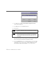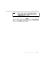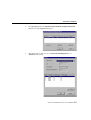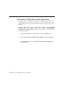
1
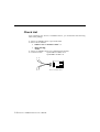
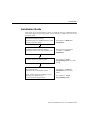
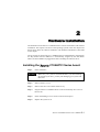
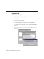
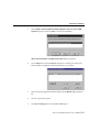
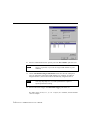
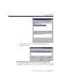
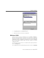
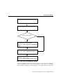
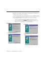
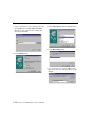
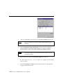
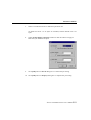
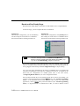
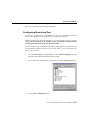
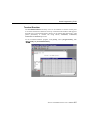
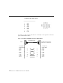
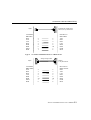
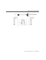
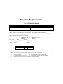
Smartio C104H/PCI Series User’s Manual Smartio 4 Ports Serial Board for PCI Bus Jun. 1999 (2nd Edition) The content of this manual is also available in CD-ROM and at Moxa Web Site. Moxa Technologies Co., Ltd. Tel: +866-2-8665-6373 Fax: +886-2-8665-6372 www.moxa.com [email protected] Smartio C104H/PCI Series User’s Manual The product described in this manual is furnished under a license agreement and may be used only in accordance with the terms of the agreements. Copyright Notice Copyright 1999 Moxa Technologies Co., Ltd. All rights reserved. Reproduction in any form without permission is prohibited. Trademarks MOXA is a registered trademark of Moxa Technologies Co., Ltd. All other trademarks or registered marks in this manual belong to their respective manufacturers. Disclaimer Information in this document is subject to change without notice and does not represent a commitment on the part of Moxa. Moxa provides this document as is, without warranty of any kind, either expressed or implied, including, but not limited to, the particular purpose. Moxa may make improvements and/or changes in this manual or in the product(s) and/or the program(s) described in this manual at any time. Information provided in this manual is intended to be accurate and reliable. However, Moxa Technologies assumes no responsibility for its use, or for any infringements of rights of the fourth parties which may result from its use. This product could include technical or typographical errors. Changes are periodically made to the information herein; these changes may be incorporated in new editions of the publication. MOXA Internet Services Customer’s satisfaction is always our number one concern. To ensure that customers get the full benefit of our services, Moxa Internet Services have been built for technical support, product inquiry, new driver update, user’s manual update, etc. The followings are the services we provide. E-mail for technical support address: [email protected] FTP site for free driver update address: ftp.moxa.com or ftp.moxa.com.tw user ID: ftp password: your_email_address World Wide Web (WWW) Site for product info address: www.moxa.com or www.moxa.com.tw About This Manual This manual is composed of six Chapters and one Appendix. This manual is written for installer, system administrator and software programmer. If you are a first-time installer and system administrator, we recommend you to go through the whole manual except Chapter 4 “Serial Programming Tools”. If you are a software programmer, you may refer to Chapter 4 “Serial Programming Tools”. If you need cable wiring information, please see Chapter 5 “Connection Cable and Cable Wiring”. If you encounter any problem during installation, please refer to Chapter 6 “Troubleshooting”. + In this manual, C104H/PCI Series refers to C104H/PCI and C104HS/PCI. Chapter 1 Introduction This chapter gives the overview and features for C104H/PCI Series. Check list and overall installation guide are also included. Chapter 2 Hardware Installation This chapter gives details of how to do hardware installation for C104H/PCI Series and connection cable. Chapter 3 Software Installation This Chapter describes the software installation, board and ports configuration, driver update and removal for various operating systems: Windows NT, and Windows 95/98. Chapter 4 Serial Programming Tools This Chapter roughly describes the programming tools for various O.S. platforms, including PComm Lite under Windows NT and Windows 95/98. Chapter 5 Connection Cable and Cable Wiring This Chapter describes the RS-232 cable wiring for the connection cable. Chapter 6 Troubleshooting This Chapter describes error might happen and possible solutions for C104H/PCI Series. Appendix Technical Reference This chapter describes specification, PCI, UART and DB37 pinouts. Table of Contents Introduction ................................................................................ 1-1 Overview----------------------------------------------------------------------------------------------------------1-1 Features ----------------------------------------------------------------------------------------------------------1-3 Check List --------------------------------------------------------------------------------------------------------1-4 Installation Guide -----------------------------------------------------------------------------------------------1-5 Hardware Installation ................................................................ 2-1 Installing the Smartio C104H/PCI Series board ---------------------------------------------------------2-1 Connecting the Fan-out Cable ------------------------------------------------------------------------------2-2 Software Installation.................................................................. 3-1 Windows NT -----------------------------------------------------------------------------------------------------3-1 Installing Driver----------------------------------------------------------------------------------------------3-2 Configuring Board and Port ------------------------------------------------------------------------------3-8 Updating Driver-------------------------------------------------------------------------------------------- 3-12 Removing Driver ------------------------------------------------------------------------------------------ 3-12 Windows 95/98------------------------------------------------------------------------------------------------ 3-13 Installing Driver-------------------------------------------------------------------------------------------- 3-14 Configuring Board and Port ---------------------------------------------------------------------------- 3-23 Updating Driver-------------------------------------------------------------------------------------------- 3-25 Removing driver------------------------------------------------------------------------------------------- 3-27 Serial Programming Tools .......................................................... 4-1 PComm Installation -----------------------------------------------------------------------------------------------4-1 PComm Programming Library ---------------------------------------------------------------------------------4-2 Utility---------------------------------------------------------------------------------------------------------------4-2 Connection Cable and Cable Wiring........................................... 5-1 RS-232 Cable Wiring ------------------------------------------------------------------------------------------5-1 Troubleshooting ......................................................................... 6-1 General Troubleshooting -------------------------------------------------------------------------------------6-1 Windows NT -----------------------------------------------------------------------------------------------------6-2 Windows 95/98--------------------------------------------------------------------------------------------------6-3 Technical Reference ................................................................. A-1 Specification ---------------------------------------------------------------------------------------------------- A-1 PCI ---------------------------------------------------------------------------------------------------------------- A-1 UART 16C550C------------------------------------------------------------------------------------------------ A-2 DB37 Connector Pinouts ------------------------------------------------------------------------------------ A-3 1 1 Introduction Overview Smartio - The Smart Multiport Async Solution The term Smartio represents smart multiport serial I/O solution. The Smartio C104H/PCI Series boards, including C104H/PCI and C104HS/PCI, are designed for 32-bit PCI bus with Plug and Play feature. They offer 4 RS-232 serial ports for connecting terminals, modems, printers, scanners, cash registers, bar code readers, keypads, numeric displays, electrical weighing machines, data acquisition equipment and many other serial devices to the PC and its compatible systems. With a well-designed and fine-tuned device driver, the Smartio board makes full use of the 32 byte Tx/Rx FIFO and on-chip H/W flow control, which makes it possible transferring data without loss at high speed as 921.6 Kbps. They offer a reliable and high performance solution for serial multiport communications. Board Applications The board applies for many applications. Here are a few: l Internet/Intranet Connection l Remote Access Application l Multi-user Application l Industrial Automation l Office Automation l Telecommunication Smartio C104H/PCI Series User’s Manual 1-1 l PC-based (vending) Machine or Kiosk System l Point-of-Sale (POS) System PCI Solution The board complies with PCI Spec. 2.1 needing neither switch nor jumper. The hardware configuration for the IRQ and Memory addresses is automatically assigned by the PCI BIOS. Hence, the board MUST be plugged first before installing the software driver. For more PCI information, please refer to Appendix “Technical Reference”. Surge Protection To prevent the board from damage caused by lightning or high potential voltage, TVSS (Transient Voltage Surge Suppressor) technologies are used in some connection options to protect the multiport controller. This is remarkably required for harsh environment such as factory, severe weather such as lightning, or other high interference situations. Operating System Support With user-friendly installation, configuration and performance, it supports Windows NT, Windows 95/98 and DOS. MOXA Serial Comm Tool For application development, MOXA provides an easy-to-use serial communication library (P PComm) under Windows NT and Windows 95/98. With this library, it is easy to develop your own applications using sample applications developed with Visual Basic, Visual C++, Borland Delphi, etc. Utilities, such as diagnostic, monitor, terminal emulation, etc., are also included for debugging and monitoring the communication status, terminal emulation, and even file transferring. 1-2 Smartio C104H/PCI Series User’s Manual Introduction Features The Smartio C104H/PCI Series consists of members as follows: C104H/PCI: 4 RS-232 ports, high speed 16C550C or compatible UART C104HS/PCI: 4 RS-232 ports, surge protection, 16C550C or compatible UART v v v v v v v Support PCI, Plug and play, no switch, no jumper Reliability¡ÐHigh speed 16C550C Communication Controllers with on-chip hardware flow control guarantees no data loss Compact size design, half size Surge protection (C104HS/PCI) Easy installation¡Ð32-bit PCI bus with Plug and Play capability Powerful Serial Comm tool¡ÐPComm Popular OS support¡ÐWindows NT, Windows 95/98 and DOS C104H/PCI Series Windows NT 3 Windows 95/98 3 DOS R 3: Driver supported by Moxa and shipped with product R: Driver supported by Moxa and shipped by request Note: Download the latest versions of drivers from the MOXA FTP service Smartio C104H/PCI Series User’s Manual 1-3 Check List Upon unpacking the Smartio C104H/PCI Series, you should find the following items in the package: v v Smartio C104H/PCI Series 4 port serial board Device driver diskettes: l Windows NT and Windows 95/98 ¡Ñ1 l v v PComm Lite ¡Ñ ¡Ñ1 Smartio C104H/PCI Series User’s Manual (This manual) Connection cable Opt4C:DB37 to DB25¡Ñ4 or Opt4D:DB37 to DB9¡Ñ4 P1 P2 P3 P4 1-4 Smartio C104H/PCI Series User’s Manual Smartio C104H/PCI Series Introduction Installation Guide This section gives a brief summary of how to install the Smartio C104H/PCI Series under each supported operating system. The installation is simple and involves the following stages: Check the PCI BIOS settings Install the Smartio C104H/PCI Series board and the connection cable See Chapter 2 “Hardware Installation” Install the software from the diskette Configure the driver for the board and ports See respective O.S. Section in Chapter 3 “Software Installation” Connect the devices with the cable See Chapter 4 “Serial Programming Tools” for cable wiring Restart the system Check the driver initialization status See Chapter 3 “Software Installation” for board init. status. If the system restart successfully, you may develop your applications or execute the desired applications See Chapter 4 “Serial Programming Tools” Smartio C104H/PCI Series User’s Manual 1-5 1-6 Smartio C104H/PCI Series User’s Manual 2 2 Hardware Installation The installation of the Smartio C104H/PCI Series consists of hardware and software installation. The respective sections of the operating systems in the next chapter will discuss more about the software installation. The hardware installation is described in this chapter. The no-switch-no-jumper Smartio C104H/PCI Series board hardware configuration for IRQ number and I/O addresses is automatically assigned by the PCI BIOS. Hence, the board MUST be plugged first before installing the software driver. Installing the Smartio C104H/PCI Series board Step 1: Power off the PC. Warning! Make sure your system is switched off before you start installing any board. If you don’t, you may risk damaging your system and the board. Step 2: Remove the PC’s cover. Step 3: Remove the slot cover bracket if there is any. Step 4: Plug the Smartio C104H/PCI Series control board firmly into a free 32bit PCI slot. Step 5: Fasten the holding screw to fix the control board in place. Step 6: Replace the system cover. Smartio C104H/PCI Series User’s Manual 2-1 Connecting the Fan-out Cable Step 7: Connect the connection cable. P1 P2 Smartio C104H/PCI Series P3 P4 Step 8: Note! Step 9: Power on the PC and the BIOS will automatically set the IRQ and I/O address. Each board must occupy one unique IRQ and four 8-byte I/O addresses, which are assigned automatically by the PCI BIOS. However, you can select a free IRQ number manually via the PC’s BIOS setup for the PCI slot, but normally this method is not available for the I/O address. The possible IRQ numbers are 2, 3, 4, 5, 7, 10, 11, 12, and 15. The possible I/O addresses are from 0x0000 to 0xFFFF. Proceed with the software installation detailed in the next chapter, “Software Installation”. 2-2 Smartio C104H/PCI Series User’s Manual 3 3 Software Installation In this chapter, the software driver installation, configuration and driver update/removal procedures are described for various operating systems, including Windows NT, and Windows 95/98. Before proceeding with the software installation, complete the hardware installation first. If it is required to develop your own applications, please refer to the next chapter, “Serial Programming Tools” for serial programming issues. Windows NT Windows NT supports up to 256 serial ports, from COM1 to COM256. To fully utilize the advanced features of Windows NT, multi-process, multi-thread, and pure 32-bit Windows NT device drivers are developed for the Smartio C104H/PCI Series and other MOXA multiport boards. The drivers conform to Win32 COMM API standard. To install the driver for the very first time, please go directly to Section “Installing Driver”. To re-configure the board and port for installed boards, please refer to Section “Configuring Board and Port”. To update the driver for installed boards, please refer to Section “Updating Driver”. To remove the driver, please go to Section “Removing Driver”. Smartio C104H/PCI Series User’s Manual 3-1 Installing Driver First Time Installing Driver Following is the procedures for installing the Smartio C104H/PCI Series driver for the first time under Windows NT 3.51/4.0. Make sure the board (s) has (have) already been plugged in the system PCI slot (s). 1. Please log in NT as Administrator. 2. Open [Control Panel], click [Network] icon and select [Adapters] tab. 3. Click [Add] button, then [Have Disk...] button in [Select Network Adapter] dialog box. 4. Specify the exact path of the driver diskette, A:\WINDOWS.NT. Then click [OK] button. 3-2 Smartio C104H/PCI Series User’s Manual Software Installation 5. Select MOXA Smartio/Industio Family multiport board in Select OEM Option dialog box, and click [OK] to start driver installation. Moxa Smartio/Industio Configuration Panel dialog box appears. 6. Click [Add] button to open Property dialog box to change port setting and advanced FIFO configuration done automatically by the system. 7. Select the newly plugged C104H/PCI board from the Board Type pull-down list. 8. Click on a specific port Item. 9. Click [Port Setting] button to open Port X dialog box. Smartio C104H/PCI Series User’s Manual 3-3 10. Select a COM number for the specific port from Port Number pull-down list. Note! Step 11 is optional, if you want to assign COM numbers to ports manually. 11. Check Auto Enumerating COM Number check-box then the subsequent ports are mapped to continuous COM numbers. For example, if COM 3 is assigned to Port 1, then COM 4 will be automatically assigned to Port 2. Note! You may skip Step 12 to 15, if the system doesn’t require a special performance tuning. 12. Select an Rx FIFO Trigger from Rx FIFO Trigger pull-down list. Rx FIFO trigger levels, at 1, 4, 8 or 14 bytes, are available, and the default value is 14 bytes. 3-4 Smartio C104H/PCI Series User’s Manual Software Installation 13. Check Set the change to all ports check-box then if desire to apply Rx FIFO Trigger just defined to all ports. 14. Select a Tx FIFO Size from Tx FIFO Size pull-down list. Tx FIFO sizes from 1 to 16 bytes are available, and the default value is 16 bytes. 15. Check Set the change to all ports check-box then the if desire to apply Tx FIFO Size just defined to all ports. 16. Click [OK] button in Port X dialog box to confirm the port setting. 17. Click [OK] button in Property dialog box to complete the port setting and return to MOXA Smartio/Industio Configuration Panel dialog box. Now the configured C104H/PCI Series board item will be shown in MOXA Smartio/Industio Configuration Panel dialog box. Smartio C104H/PCI Series User’s Manual 3-5 18. Click [OK] button in MOXA Smartio/Industio Configuration Panel to return to Network dialog box. 19. Click [OK] button in to exit Network dialog box. 20. Restart the PC. Note! The driver configuration will NOT take effect until you restart the PC. Note! Double check if all the Smartio C104H/PCI Series components – the control board and the external 1X4 cable – are connected and fastened tightly to make sure that the system and the driver start successfully. Once the system restarts, you may check the event log issued by the MOXA driver to see if the ports of the board are initialized successfully. 21. Enter the [Administrative] group, click [Event Viewer] icon and select [Log] and [System] to check a message similar to “MOXA C104PCI series, with first serial port COM3, has been enabled” for each configured board. 3-6 Smartio C104H/PCI Series User’s Manual Software Installation Note! If an error message similar to “Cannot find any configured MOXA Smartio/Industio series board!” pops up, refer to the Troubleshooting chapter for solutions. Once the board and the driver are installed and the driver restarts successfully, you can start to develop applications with the PComm library (See “Serial Programming Tools”) or the Microsoft Win32 API. You can also execute any ready-made applications, such as PComm utility Terminal emulator (See “Serial Programming Tools”) or HyperTerminal to transmit/receive data, as well as Remote Access Service to provide dial-up networking capabilities. Smartio C104H/PCI Series User’s Manual 3-7 Configuring Board and Port Re-configure Port Setting If the driver is installed and only desire to re-configure the ports, please refer to the following procedures. Except procedures listed below, it is also allowed to do so by clicking [Start] è [Program Files] è [MOXA Utility] è [MOXA Smartio/Industio Configuration Panel] è [Property] and then also refer to step 6-21 in the previous section “First Time Installing Driver”. 1. Open [Control Panel], click [Network] icon and select [Adapters] tab. 2. Click on MOXA Smartio/Industio Family Adapter in Network Adapters list 3. Click [Properties] button to open MOXA Smartio/Industio Configuration Panel dialog box to change port setting and advanced FIFO configuration. 3-8 Smartio C104H/PCI Series User’s Manual Software Installation 4. Click [Property] button in MOXA Smartio/Industio Configuration Panel dialog box to open Property dialog box. 5. Then please refer to Step 6 to 21 in “First Time Installing Driver” of “Windows NT” section. Smartio C104H/PCI Series User’s Manual 3-9 Add Another C104H/PCI Series Board Configuration If another MOXA C104H/PCI Series board is plugged and needed to be reconfigured, please see this section for details. Up to four C104H/PCI Series board can be installed in ONE system under Windows NT as long as the system sources is sufficient. Except procedures listed below, it is also allowed to do so by clicking [Start] è [Program Files] è [MOXA Utility] è [MOXA Smartio/Industio Configuration Panel] è [Add] and then also refer to step 7-21 in the previous section Installing Driver. 1. Open [Control Panel], click [Network] icon and select [Adapters] tab. 2. Click on MOXA Smartio/Industio Family Adapter in Network Adapters list. 3. Click [Properties] button to open Moxa Smartio/Industio Configuration Panel dialog box. 3-10 Smartio C104H/PCI Series User’s Manual Software Installation 4. Then please refer to Step 6 to 21 in “First Time Installing Driver” of “Windows NT” section. Remove Existing C104H/PCI Series Board Configuration By unplugging C104H/PCI board, the system will automatically remove the configuration. Therefore, there is no need to do remove action from Moxa Smartio C104H/PCI Series User’s Manual 3-11 Smartio/Industio Configuration Panel dialog box. Updating Driver To update the driver for the Smartio C104H/PCI Series board, simply follow the following procedures. 1. Open [Control Panel], click [Network] icon, and select [Adapters] tab. 2. Click on MOXA Smartio/Industio Family Adapter in the Network Adapter list. 3. Click [Remove] button in Network dialog box. 4. Click [Close] button in Network dialog box. 5. Restart the system. 6. Please refer to Step 1 to 21 in “First Time Installing Driver” of “Windows NT” section to install the new driver. Removing Driver To remove the driver for the Smartio C104H/PCI Series board, 1. Open [Control Panel], click [Network] icon, and select [Adapters] tab. 2. Click on MOXA Smartio/Industio Family Adapter in the Network Adapter list. 3. Click [Remove] button in Network dialog box. 3-12 Smartio C104H/PCI Series User’s Manual Software Installation 4. Click [Close] button to exit Network dialog box. 5. Restart the system to activate the new configuration. Windows 95/98 Windows 95/98 driver supports up to 128 serial ports, from COM1 to COM128. To fully utilize the advanced features of Windows 95/98, multi-process, multi-thread and pure 32-bit Windows 95/98 virtual device port drivers (VxD) compliant with communication drivers (VCOMM) are developed for the Smartio C104H/PCI Series and other MOXA multiport boards. The drivers conform to the Win32 COMM API standard. To install the driver for the first time, or to add more boards, please go directly to Section “Installing Driver”. To re-configure the ports for installed boards, please refer to Section “Configuring Smartio C104H/PCI Series User’s Manual 3-13 Board and Port”. To update the driver, please go to Section “Updating Driver”. To remove the driver, please go to Section “Removing Driver”. Installing Driver You can easily plug the Smartio C104H/PCI Series board and work right away with very little installation efforts under Windows 95/98 supporting Plug and Play capability. Windows 95/98 will automatically detect the presence of the newly plugged board and prompt you to install the software driver for the first time. In this case, you need the driver diskette. At most 4 Smartio C104H/PCI Series boards can be installed in ONE system as long as the I/O addresses and IRQ number resources are sufficient and available in the system. The following flow chart illustrates the driver installation stages of the Smartio C104H/PCI Series boards. Each stage will be discussed later. 3-14 Smartio C104H/PCI Series User’s Manual Software Installation Install the Smartio PCI board in the system Start Windows 95/98 to detect the board Driver installed before? Yes No Install the driver with the diskette See Section “First Time Driver Installation Stage” Configure the port See Section “Port Configuration Stage” The ports of the Smartio C104H/PCI Series Board are ready to work. See Section “Board and Port Ready Stage” First Time Driver Installation Stage This stage presents the steps for installing the driver for the first time of the first Smartio C104H/PCI Series board. The installation of the Smartio C104H/PCI Series board for Windows 95 and Windows 98 are slightly different and will be Smartio C104H/PCI Series User’s Manual 3-15 described in two columns. Follow the steps in the left column for Windows 95 or the right column for Windows 98 respectively. If one MOXA C104H/PCI Series board had been previously installed and another MOXA C104H/PCI Series board was plugged, the system will prompt you to do Port Configuration Stage discussed in the next section and skips this stage. 1. Upon detecting the first new Smartio C104/PCI Series board, Windows 95/98 will automatically display a New hardware found message box, and then pop up the following dialog boxes. Click Next button. Windows 95 Windows 98 2. Click [Other Locations] button. 2. Select [Display a list...] and click [Next] button. 3-16 Smartio C104H/PCI Series User’s Manual Software Installation Smartio C104H/PCI Series User’s Manual 3-17 3. Type A:\Windows.95 in the Location field, and click [OK] button in Select Other Location dialog box. The system will start reading the files from the diskette. 3. Select Other Devices and click [Next] button. 4. Click [Have Disk] button. 4. Click [Finish] button. 5. Type A:\Windows.95 and click [OK] button. The system will start reading the files from the diskette. 3-18 Smartio CC104H/PCISeries User’s Manual Software Installation 6. Click [Next] button. 7. Click [Next] button. Port Configuration Stage After the driver is installed, MOXA C104 PCI Series Installation dialog box will be displayed automatically and the port mapping is automatically done by the system. If one MOXA C104H/PCI Series board had installed previously and another MOXA C104H/PCI Series board was plugged, the system will prompt you to do port configuration directly discussed in this section. 1. Click on a specific port. 2. Click [Port Setting] button to open Port X dialog box. Smartio C104H/PCI Series User’s Manual 3-19 3. Select a COM number for the specific port from Port Number pull-down list. Note! 4. Check Auto Enumerating COM Number check-box then the subsequent ports are mapped to continuous COM numbers. For example, if COM 3 is assigned to Port 1, then COM 4 will be automatically assigned to Port 2. Note! 5. Step 4 is optional, if you want to assign COM numbers to Ports manually. You may skip Step 5 to 8, if the system doesn’t require a special performance tuning. Select an Rx FIFO Trigger from Rx FIFO Trigger pull-down list. Rx FIFO trigger levels, at 1, 4, 8 or 14 bytes, are available, and the default value is 14 bytes. 6. Check Set the change to all ports check-box then if desire to apply Rx FIFO Trigger just defined to all ports. 3-20 Smartio C104H/PCI Series User’s Manual Software Installation 7. Select a Tx FIFO Size from Tx FIFO Size pull-down list. Tx FIFO sizes from 1 to 16 bytes are available, and the default value is 16 bytes. 8. Check Set the change to all ports check-box then the if desire to apply Tx FIFO Size just defined to all ports. 9. Click [OK] button in Port X dialog box to confirm the port setting. 10. Click [OK] button in Property dialog box to complete the port setting. Smartio C104H/PCI Series User’s Manual 3-21 Board and Port Ready Stage Board and Port Ready Stage for Windows 95 and Windows 98 is a slight different. In this last stage, you will complete the driver installation. Windows 95 After the port configuration, you can immediately use the COM ports of the Smartio C104H/PCI Series board without restarting Windows 95. Note! Windows 98 After the port configuration, click [Finish] button. The COM ports of the Smartio C104H/PCI Series board can be used without restarting Windows 98. If an error message similar to “C104PCI Series(BusNo=x, DevNo=x, Port1=COMx) interrupt number is invalid!” pops up, refer to “Troubleshooting” chapter for solutions. If you want to add more boards while the driver has been installed, simply plug the Smartio C104H/PCI Series board and Windows 95/98 will automatically detect the newly plugged board and skip to Port Configuration stage to do port setting. Up to now, the driver installation of the Smartio C104H/PCI Series is complete and successful, including the board and port configuration. However, if changes of the board and port configuration are needed, please refer to the next section, “Configuring Board and Port”, for more configuration details. Once the board and the driver are installed and the driver restarts successfully, you can start to develop applications with the PComm library (See “Serial Programming Tools”) or the Microsoft Win32 API. You can also execute any ready-made applications, such as PComm utility Terminal emulator (See “Serial Programming Tools”) or HyperTerminal to transmit/receive data, as well as Remote Access 3-22 Smartio C104H/PCI Series User’s Manual Software Installation Service to provide dial-up networking capabilities. Configuring Board and Port If desire to re-configure the COM number for the ports of installed boards and drivers under Windows 95/98, please follow procedures listed below. Instead of following procedures listed below, it is also allowed to do so by clicking [Start] è [Program Files] è [MOXA Utility] è [MOXA Smartio/Industio Configuration Panel] è [Property] è [Port Setting]. For this is a PCI board, once the board is added or unplugged, the configuration will be automatically added or removed by the system. Thus, it saves your effort to do add or remove action. 1. Open [Control Panel], click [System] icon, select [Device Manager] tab, and then select Moxa Smartio/Industio multiport board. 2. Click on desired C104H/PCI Series board entry, and click [Properties] button. 3. Select [Ports Configuration] tab. Smartio C104H/PCI Series User’s Manual 3-23 4. Click on the specific port and click [Port Setting] button to re-assign the desired COM number for the Smartio C104H/PCI Series port mapping. Note! 5. Check Auto Enumerating COM Name check-box to assign continuous COM numbers for subsequent ports. For example, if COM 3 is assigned to Port 1, then COM 4 will be automatically assigned to Port 2. Note! 6. Step 5 is optional, if you want to assign COM numbers to Port manually. Step 6 and 7 are optional, if the system doesn’t require a special performance tuning. Re-assign the Rx FIFO Trigger by selecting a number from the pull-down list. Check Set the change to all ports check-box if desire to apply this setting to all ports. Rx FIFO trigger levels, at 1, 4, 8 or 14 bytes, are available, and the default value is 14 bytes. 7. Re-assign the Tx FIFO Size by selecting a number from the pull-down list. 3-24 Smartio C104H/PCI Series User’s Manual Software Installation Check Set the change to all ports check-box if desire to apply this setting to all ports. Tx FIFO sizes from 1 to 16 bytes are available, and the default value is 16 bytes. 8. Click [OK] button in Port X dialog box. 9. Click [OK] button in C104 PCI Series Properties dialog box. 10. Click [OK] button in Device Manager tab. 11. Restart the system to activate the latest configuration. Updating Driver This section will discuss how to update the Windows 95/98 driver to enhance the function of the board. 1. Open [Control Panel], click [System] icon, and select [Device Manager] tab. Smartio C104H/PCI Series User’s Manual 3-25 2. Click on MOXA C104 PCI Series and click [Properties] button 3. Select [Driver] tab. 4. Click [Update Driver...] button. 5. Click [Have Disk...] button and type the path of the new driver. 3-26 Smartio C104H/PCI Series User’s Manual Software Installation 6. Insert the source diskette in the floppy drive if there is any. 7. Click [OK] button in Install from Disk dialog box. 8. The system will automatically prompt you to restart the system, click [Yes] button to restart the system. Or [No] button if you want to reboot the system later. Removing driver This section explains how to remove the Smartio C104H/PCI Series board driver. 1. Open [Control Panel] icon, double click [Add/Remove Programs] icon, and then select [Install/Uninstall] tab. 2. Click on MOXA Smartio/Industio Driver option and then click [Add/Remove] button to start the driver removal. Smartio C104H/PCI Series User’s Manual 3-27 3. Click [Yes] button in the following shown message box to confirm the driver removal. 4. Click [OK] button in Add/Remove Programs Properties dialog box. 3-28 Smartio C104H/PCI Series User’s Manual 4 4 Serial Programming Tools Moxa supports some easy but powerful serial programming libraries and communication troubleshooting utilities under Windows NT and Windows 95/98. It will save your developing time with the MOXA Serial Programming Tools. The following sections will detail the installation, the library and the utilities for various platforms. PComm, the professional serial comm tool for PC, is a software package for Windows NT and Windows 95/98 consisting of: l a powerful serial communication library for easy programming in the most popular languages. The serial communication library is useful for developing an application for data communication, remote access, data acquisition or industrial control in Windows NT or Windows 95/98 environment. Also it is an easier solution compared to the more complex Windows Win32 COMM API, l useful utilities such as diagnostic, monitor and terminal emulator, l illustrative sample programs, l comprehensive on-line documents. PComm Installation To install PComm, run \Setup.exe from the diskette enclosed in the package. Please note that the PComm diagnostic and monitor utilities are for MOXA boards only; therefore, these two utilities won’t work on other serial boards but only on MOXA boards. After PComm is successfully installed, simply click [Start] and select [Program Files] and the PComm Lite group to select a list of utilities and documents. Smartio C104H/PCI Series User’s Manual 4-1 PComm Programming Library The serial communication library helps you to develop programs for serial communications for any COM port complying with Microsoft Win32 API. It facilitates the implementation of multi-process and multi-thread serial communication programs and hence remarkably reduces developing time. This serial communication library provides a complete library function and sample programs for Visual C++, Visual Basic and Delphi. To view the detailed function PCo m m description and sample programs, please click [Start]è[Program Files] è[P Lite]è[P PComm Lib Help], [P PComm Porting Notes] or [P PComm Programming Guide] or refer to the sample programs in the PComm directory. Utility The followings are brief descriptions of each utility. For more information about each utility, please see the on-line help in the diskette. 4-2 Smartio C104H/PCI Series User’s Manual Serial Programming Tools Diagnostic (for MOXA boards only) A convenient diagnostic program ONLY for MOXA boards and ports provides internal and external testing including IRQ, TxD/RxD, UART, CTS/RTS, DTR/DSR, DTR/DCD testing, etc. It will verify if both the software and hardware function correctly. To run Diagnostic program, click [Start]; select [Program Files] then [P PComm Lite] and [Diagnostic]. Smartio C104H/PCI Series User’s Manual 4-3 Monitor (for MOXA boards under Windows NT Only) A useful port status monitoring program allows you to watch over the selected MOXA COM ports. It monitors data transmitting/receiving throughput and communication line status that are updated and displayed on the screen at time intervals. By clicking on the specific displayed port, you can visualize the current communication parameters and status of that port. PComm Lite] To run Monitor program, click [Start]; select [Program Files] then [P and [Monitor]. 4-4 Smartio C104H/PCI Series User’s Manual Serial Programming Tools Terminal Emulator The Terminal Emulator obviously serves as an emulator to connect various ports to see if the transmission functions correctly. It features multi-windows and supports terminal types of VT100 and ANSI. It allows you to transfer data interactively, send pattern periodically or transfer file using ASCII, XMODEM, YMODEM, ZMODEM and KERMIT protocols. To run Terminal Emulator program, click [Start], select [Program Files], then [P PComm Lite] and [Terminal Emulator]. Smartio C104H/PCI Series User’s Manual 4-5 4-6 Smartio C104H/PCI Series User’s Manual 5 5 Connection Cable and Cable Wiring This chapter will illustrate the possible connections and cable wiring for C104H/PCI Series board. In serial data communications, the term DTE is Data Terminal Equipment, such as PC COM1/2, serial printers and terminals. The term DCE is Data Communication Equipment, like modems. RS-232 Cable Wiring The followings are pin assignments for two connection cables for C104H/PCI Series board: C104H/PCI DB25 Male (Opt4C) 2 3 4 5 6 7 8 20 TxD RxD RTS CTS DSR GND DCD DTR Smartio C104H/PCI Series User’s Manual 5-1 C104H/PCI DB9 Male (Opt4D) 1 2 3 4 5 6 7 8 DCD RxD TxD DTR GND DSR RTS CTS According to cable options and devices connected, several possible connection types are illustrated as below. Type 1: To connect C104H/PCI Series to a DTE device. Null Modem Cable PC COM2 port, Serial Printer, Terminal, or any DTE Device Opt4C C104H/PCI DB25 Male TxD RxD RTS CTS DSR DTR GND DCD 2 3 4 5 6 20 7 8 5-2 Smartio C104H/PCI Series User’s Manual 2 3 4 5 6 20 7 8 DTE Device DB25 Male TxD RxD RTS CTS DSR DTR GND DCD Connection Cable and Cable Wiring PC COM2 port, Serial Printer, Terminal, or any DTE Device Opt4D C104H/PCI DB9 Male RxD TxD CTS RTS DTR DSR GND DCD 2 3 8 7 4 6 5 1 2 3 4 5 6 20 7 8 DTE Device DB25 Male TxD RxD RTS CTS DSR DTR GND DCD Type 2: To connect C104H/PCI Series to a DCE device. Straight-through Cable Modem, or any DCE Device Opt4C C104H/PCI DB25 Male TxD RxD RTS CTS DSR DTR GND DCD 2 3 4 5 6 20 7 8 2 3 4 5 6 20 7 8 DCE Device DB25 Female RxD TxD CTS RTS DTR DSR GND DCD Smartio C104H/PCI Series User’s Manual 5-3 Modem or any DCE Device Opt4D C104H/PCI DB9 Male RxD TxD CTS RTS DTR DSR GND DCD 2 3 8 7 4 6 5 1 2 3 4 5 6 20 7 8 DCE Device DB25 Female RxD TxD CTS RTS DTR DSR GND DCD Type 3: To connect C104H/PCI Series to a DTE with 3-pin wiring. If the Hardware flow control feature is set to ON, you must loop back (or short) the RTS with CTS and DSR with DTR, DCD on MOXA site, indicated in dashlines of the following diagrams. If the Hardware flow control feature is set to OFF, you could just leave RTS, CTS, DSR, DTR, DCD open, ignoring the connection indicated in dash-lines. PC COM2 port, Serial Printer, Terminal, or any DTE Device Opt4C C104H/PCI DB25 Male TxD RxD GND RTS CTS DSR DTR DCD 2 3 7 4 5 6 20 8 5-4 Smartio C104H/PCI Series User’s Manual 2 3 7 4 5 6 20 8 DTE Device DB25 Male TxD RxD GND RTS CTS DTR DSR DCD Connection Cable and Cable Wiring PC COM2 port, Serial Printer, Terminal, or any DTE Device Opt4D C104H/PCI DB9 Male RxD TxD GND RTS CTS DTR DSR DCD 2 3 5 7 8 4 6 1 2 3 7 4 5 6 20 8 DTE Device DB25 Male TxD RxD GND RTS CTS DTR DSR DCD Smartio C104H/PCI Series User’s Manual 5-5 5-6 Smartio C104H/PCI Series User’s Manual 6 6 Troubleshooting Common Smartio C104H/PCI Series errors and possible corresponding solutions are listed below. If the problem still cannot be solved by following solutions given, contact dealers or Moxa for help or use the Problem Report Form at the end of this manual to report problems to your dealer at once for faster technical support. General Troubleshooting 1. The MOXA PCI board cannot be detected by the MOXA driver while installing the driver. Hardware causes and solutions: A. The board is not installed or missing (absent). Please install it. 2. B. The board is not properly plugged in the system. If that is the case, replug the board in a 32-bit PCI slot this time. Sometimes the slot for plugging the board is malfunctioned. In this case, try other slots until you find a good one. C. The motherboard does not have an available IRQ for the C104H/PCI Series board. Please enter BIOS and make sure there are available IRQ in PCI/PnP settings. The MOXA board and driver are activated but cannot transfer (transmitting/receiving) data. Hardware Causes and Solutions: A. Check if cable wiring is connected correctly. Please refer to the “Connection Cable and Cable Wiring” chapter for correct cable connection. B. The cable or the board are probably defective. Please try other ports, cables or boards to verify it. Or use PComm Diagnostic utility testing Smartio C104H/PCI Series User’s Manual 6-1 MOXA boards and port conditions. If Diagnostic reports error, replace the malfunctioned faulty components. Software Causes and Solutions: A. Smartio C104H/PCI Series board will check the line status (CTS) before transmitting data if the RTS/CTS flow control feature is set to Enable in the configuration or application program. Please refer to the Connection Cable and Cable Wiring chapter for proper wiring and check the line status of the suspected port using the diagnostic LED indicators on the mini tester. B. The board controlling application might not be correctly written according to the corresponding API of the operating system. To verify the problem, please run another existing and known good application or the utilities provided by Moxa. Such as Pcomm Terminal emulator or HyperTerminal under Windows NT and Windows 95/98. Windows NT This section is specific for troubleshooting under Windows NT. For general problems and solutions, please see the previous section, General Troubleshooting. 1. After the system reboots, the error message Another driver in the system, which did not report its resources, has already claimed the interrupt used by xxx. appears in the Event Log. This indicates the MOXA board is found, but the IRQ is conflicting with another adapter. Please check the PCI BIOS IRQ settings first and then select an IRQ that is available. 2. After the system reboots, the error message “Cannot find any configured MOXA Smartio/Industio series board!” appears in the Event Log. Please make sure the PCI board is seated firmly in the expansion slot. 3. The COM number of the Smartio C104/PCI Series (Bus No=x Dev No=x, Port1=COMx), with device number xx, conflicts with others. The COM numbers for different boards are conflicting. Change the COM number mappings for MOXA boards. 6-2 Smartio C104H/PCI Series User’s Manual Troubleshooting 4. Windows NT system panic (blue screen). The possible reason is an IRQ or I/O address conflict with other ISA Bus adapters, like LAN and SCSI boards, or the system BIOS. Please refer to the corresponding problem in the previous section “General Troubleshooting” for solutions. Windows 95/98 This section is specific for troubleshooting under Windows 95/98. For general problems and solutions, please see the previous section, “General Troubleshooting”. 1. The system fails to find the Smartio C104H/PCI Series board! - The board(s) is(are) not plugged properly. - The slot with boards plugging in is defective, please try another slot until you find a good one. - The board might be defective. 2. After the system reboots, the error message “C104/PCI Series (BusNo=x, DevNo=x, Port1=COMx) interrupt number is invalid!” appears. This indicates that the MOXA board is found, but the IRQ is conflicting with other adapter. Make sure MOXA board’s IRQ is not conflicting with other adapter’s. Check the PCI BIOS IRQ settings and select an available IRQ for MOXA boards. Smartio C104H/PCI Series User’s Manual 6-3 6-4 Smartio C104H/PCI Series User’s Manual A 7 Technical Reference Specification v v v v v v v v v v v Bus interface: Number of ports: I/O address: IRQ: Data bits: Stop bits: Parity: UART: Speed (bps): Connectors: Data signals: v v Surge protection: Operating temp: v Power requirement: v Dimensions: 32-bit PCI 4 Assigned by PCI BIOS Assigned by PCI BIOS 5, 6, 7, 8 1, 1.5, 2 None, even, odd, space, mark 4¡Ñ16C550C or compatible 50 ~ 921.6K 4¡ÑDB25 male (Opt4C) or 4¡ÑDB9 male (Opt4D) RS-232¡ÐTxD, RxD, RTS, CTS, DTR, DSR, DCD, GND Max. 2000V (C104HS/PCI) 0 ~ 55 ¢J C104H/PCI: 86mA max. (+5V), 210mA max. (+12V), 266mA max.(12V) C104HS/PCI: 110mA max. (+5V), 230mA max. (+12V), 320mA max. (12V) 120 mm¡Ñ100 mm PCI The 32-bit Smartio C104H/PCI Series board complies with the PCI specifications 2.1. Hardware configuration for IRQ and I/O addresses is automatically assigned by the PCI BIOS. Hence, you must first plug the board before installing the software driver. Unlike ISA slots, different PCI slots in the same PC may have different bus numbers and device numbers with respect to the PCI specifications. The same PCI Smartio C104H/PCI Series User’s Manual A-1 board will have different system configurations if switching to a different PCI slot, which may be called slot-sensitive or slot-dependent. This may also apply to PCI slots in PC with different motherboard, which may use different device number sets. For example, some use 17, 18, 19, and 20 for identifying the respective PCI slots but some use 11, 12, 13 and 14. Due to the slot-dependency, it is necessary to re-configure the software driver once the board is plugged in different PCI slots. Up to 4 Smartio C104H/PCI Series boards are allowed in one system. When installing more than one board, please remember the order of boards for distinguishing the installed boards. UART 16C550C The UART chip 16C550C is an intelligent asynchronous controller supporting one full duplex channel that simultaneously transfers data at 921.6 Kbps speed. To increase the overall data throughput, special features such as on-chip FIFO and onchip hardware flow control are used to reduce the number of interrupts to the onboard CPU and to prevent any loss of valuable data. A-2 Smartio C104H/PCI Serieses User’s Manual Technical Reference DB37 Connector Pinouts The following lists the pin assignments of the Smartio C104H/PCI Series DB37 connector on the bracket. With this information, you may fabricate any type of fanout cables, such as DB37 to 4 x RJ45. Pin no. Signal 1 2 3 4 5 6 7 8 9 10 11 12 13 14 15 16 17 18 19 DCD3 GND CTS3 RxD3 RI4 DTR4 DSR4 RTS4 TxD4 DCD2 GND CTS2 RxD2 RI1 DTR1 DSR1 RTS1 TxD1 Pin no. 20 21 22 23 24 25 26 27 28 29 30 31 32 33 34 35 36 37 Signal RI3 DTR3 DSR3 RTS3 TxD3 DCD4 GND CTS4 RxD4 RI2 DTR2 DSR2 RTS2 TxD2 DCD1 GND CTS1 RxD1 Note: Make shield grounded to connector. Smartio C104H/PCI Series User’s Manual A-3 A-4 Smartio C104H/PCI Serieses User’s Manual Problem Report Form Smartio C104H/PCI Series Customer name: Company: Tel: Email: Fax: Date: 1. Moxa Product: C104H/PCI Series: o C104H/PCI o C104HS/PCI Serial Number:__________ 2. Moxa Driver Version: ________________ 3. Moxa Hardware Settings: PCI slot number ________________________ 4. Operating System: oWindows 95 oWindows 98 oWindows NT 3.51 oWindows NT 4.0 oDOS oOthers 5. PC Host: Make _________ Model _________ 6. CPU: Speed _____MHz Make ______ Model ______ 7. BIOS: Make __________________ Version _______ 8. PCI IRQ Configuration in BIOS: Slot no. IRQ no 1 2 3 4 9. Problem Description: Please describes the problem as clearly as possible, including the error message you see. We may have to follow your description to reproduce the problem. o Board not found. o Board found, but can’t transfer data. o Can transfer data, but lose data. o Can transfer data, but with garbled data. o Others. Detailed error message description is recommended: Return Procedure For product repair, exchange or refund, you must: v Provide evidence of original purchase. v Fill out the Problem Report Form (PRF) as detailed as possible for shorter product repair time. v Obtain a Return Merchandise Authorization (RMA) number from the sales representative or dealer. v Carefully pack the product in an anti-static package, and send it, pre-paid, to the dealer. The RMA number should be visible on the outside of the package, and include a description of the problem along with the return address and telephone number of a technical contact.