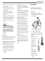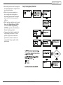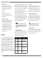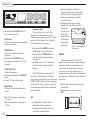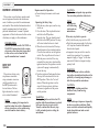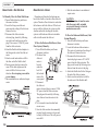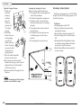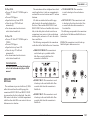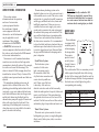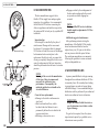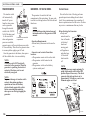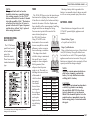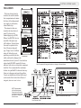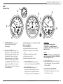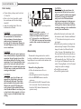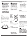
1
MONACO Limited Warranty - 2008 MONACO® MOTORHOME LIMITED WARRANTY WHAT THE PERIOD OF COVERAGE IS: This Limited Warranty provided by Monaco® (“Warrantor”) covers those components, assemblies and systems of your new motorhome not excluded under the section “What is Not Covered” and when sold by an authorized dealer, for twelve (12) months from the original retail purchase date or the first 24,000 miles of use, whichever occurs first. However, this Limited Warranty provided by Warrantor covers the steel or aluminum frame structure, only, of the sidewalls (excluding slide outs), roof, and rear and front walls for sixty (60) months from the original retail purchase date or the first 50,000 miles of use, whichever occurs first. If you use your motorhome for any rental, commercial or business purposes whatsoever, the Limited Warranty provided by Warrantor covers your new motorhome when sold by an authorized dealer for ninety (90) days from the original retail purchase date or the first 24,000 miles of use, whichever occurs first. In addition, the Limited Warranty provided by Warrantor covers the steel or aluminum frame structure, only, of the sidewalls (excluding slide outs), roof, and rear and front walls for twelve (12) months from the original retail purchase date or the first 24,000 miles of use, whichever occurs first. A conclusive presumption that your motorhome has been used for commercial and/or business purposes arises if you have filed a federal or state tax form claiming any business tax benefit related to your ownership of the motorhome. The above Limited Warranty coverage applies to all owners, including subsequent owners, of the motorhome. However, a subsequent owner must submit a warranty transfer form by filing the form through an authorized Monaco dealer. A subsequent owner’s warranty coverage period is the remaining balance of the warranty coverage period the prior owner was entitled to under this Limited Warranty. Warranty transfer forms can be obtained by contacting the Customer Relations Department. There is no charge for the transfer. LIMITATION AND DISCLAIMER OF IMPLIED WARRANTIES: IMPLIED WARRANTIES, IF ANY, ARISING BY WAY OF STATE LAW, INCLUDING ANY IMPLIED WARRANTY OF MERCHANTABILITY AND ANY IMPLIED WARRANTY OF FITNESS FOR A PARTICULAR PURPOSE, ARE LIMITED IN DURATION TO THE TERM OF THIS LIMITED WARRANTY AND ARE LIMITED IN SCOPE OF COVERAGE TO THOSE PORTIONS OF THE MOTORHOME COVERED BY THIS LIMITED WARRANTY. WARRANTOR DISCLAIMS ALL IMPLIED AND EXPRESS WARRANTIES, INCLUDING THE IMPLIED WARRANTY OF MERCHANTABILITY AND THE IMPLIED WARRANTY OF FITNESS FOR A PARTICULAR PURPOSE, ON COMPONENTS AND APPLIANCES EXCLUDED FROM COVERAGE AS SET FORTH BELOW. There is no warranty of any nature made by Warrantor beyond that contained in this Limited Warranty. No person has authority to enlarge, amend or modify this Limited Warranty. The dealer is not the Warrantor’s agent but is an independent entity. Warrantor is not responsible for any undertaking, representation or warranty made by any dealer or other person beyond those expressly set forth in this Limited Warranty. Some states do not allow limitations on how long an implied warranty lasts, so the above limitation may not apply to you. WHAT THE WARRANTY COVERS: Warrantor’s Limited Warranty covers defects in the manufacture of your motorhome and defects in materials used to manufacture your motorhome. “Defect” means the failure of the motorhome and/or the materials used to assemble the motorhome to conform to Warrantor’s design and manufacturing specification and tolerances. Also see the section “What the Warranty Does Not Cover” set out below. WHAT WE WILL DO TO CORRECT PROBLEMS: Warrantor’s sole and exclusive obligation is to repair and/or replace, at its option, any covered defect if: (1) you notify Warrantor or one of its authorized servicing dealers of the defect within the warranty coverage period and within five (5) days of discovering the defect; and (2) you deliver your Motorhome to Warrantor or Warrantor’s authorized servicing dealer at your cost and expense. It is reasonable to expect some service items to occur during the warranty period. The performance of warranty repairs shall not extend the original warranty coverage period. Further, any performance of repairs after the warranty coverage period has expired or any performance of repairs to component parts and appliances that are excluded from coverage shall be considered “good will” repairs, which shall not alter the express terms of this limited warranty. If the repair or replacement remedy fails to successfully cure a defect after Warrantor received a reasonable opportunity to cure the defect(s), your sole and exclusive remedy shall be limited to Warrantor paying you the cost of having an independent third party perform repair(s) to the defect(s). Warrantor may use new and/or remanufactured parts and/or components of substantially equal quality to complete any repair. Defects and/or damage to interior and exterior surfaces, trim, upholstery and other appearance items may occur at the factory during manufacture, during delivery of the motorhome to the selling dealer or on the selling dealer’s lot. Normally, any such defect or damage is detected and corrected at the factory or by the selling dealer during the inspection process performed by the Warrantor and the selling dealer. If, however, you discover any such defect or damage when you take delivery of the motorhome, you must notify your dealer or Warrantor within five days of the date of purchase to have repairs performed to the defect at no cost to you as provided by this Limited Warranty. If either three or more unsuccessful repair attempts have been made to correct any covered defect that you believe substantially impairs the value, use or safety of your motorhome, or repairs to any covered defect(s) which you believe substantially impairs the value, use or safety of your motorhome have taken 30 or more days to complete, you must, to the extent permitted by law, notify Warrantor directly in writing of the failure to successfully repair the defect(s) so that Warrantor can become directly involved in exercising a final repair attempt for the purpose of performing a successful repair to the identified defect(s). MONACO Limited Warranty - 2008 HOW TO GET SERVICE: The “Acknowledgement of Receipt of Warranty/Production Information” form must be returned to Warrantor promptly upon purchase to assure proper part replacement and repair of your motorhome. Failure to return the “Acknowledgement of Receipt of Warranty/Production Information” form will not affect your rights under the Limited Warranty so long as you can furnish proof of purchase. For warranty service simply contact one of Warrantor’s authorized service centers for an appointment, then deliver your motorhome (at your expense) to the service center. If you need assistance in locating an authorized warranty service facility, contact Warrantor’s Warranty Department (1-877-466-6226). The mailing address is: 91320 Coburg Industrial Way Coburg, Oregon 97408 In the event the motorhome is inoperative due to malfunction of a warranted part, Warrantor will pay the cost of having the motorhome towed to the nearest authorized repair facility provided you notify Warrantor prior to incurring the towing charges to receive directions to the nearest repair facility. Because Warrantor does not control the scheduling of service work by its authorized servicing dealers, you may encounter some delay in scheduling and/or in the completion of the repairs. WHAT THE WARRANTY DOES NOT COVER: This Limited Warranty does not cover: any motorhome sold or registered outside of the United States or Canada; items which are added or changed after the motorhome leaves Warrantor’s possession; items that are working as designed but which you are unhappy with because of the design; normal wear and usage, such as fading or discoloration of fabrics, or the effects of moisture inside the motorhome; defacing, scratching, dents and chips on any surface or fabric of the motorhome, not caused by Warrantor; owner maintenance, including by way of example wheel alignments and resealing exterior sealant areas; the automotive chassis and power train, including, by way of example the engine, drivetrain, steering and handling, braking, wheel balance, muffler, tires, tubes, batteries and gauges; appliances and components covered by their own manufacturer’s warranty including, by way of example the microwave, refrigerator, ice maker, stove, oven, generator, roof air conditioners, hydraulic jacks, VCR, television(s), water heater, furnace, stereo, radio, compact disc player, washer, dryer, inverter and cellular phone; or flaking, peeling and chips or other defects or damage in or to the exterior or finish caused by rocks or other road hazards, the environment including airborne pollutants, salt, tree sap and hail. Component part and appliance manufacturers issue limited warranties covering those portions of the motorhome not covered by the Limited Warranty issued by Warrantor. To learn more on what specific component parts and appliances are excluded from the Limited Warranty issued by Warrantor please contact your selling dealership or Warrantor directly or review the warranty packet inside the Motorhome. EVENTS DISCHARGING WARRANTOR FROM OBLIGATION UNDER WARRANTY: Misuse or neglect, accidents, unauthorized alteration, failure to provide reasonable and necessary maintenance (see Owner’s Manual), damage caused by off road use, collision, fire, theft, vandalism, explosions, overloading in excess of rated capacities, and odometer tampering shall discharge Warrantor from any express or implied warranty obligation to repair any resulting defect. DISCLAIMER OF CONSEQUENTIAL AND INCIDENTAL DAMAGES: THE ORIGINAL PURCHASER OF THE MOTORHOME AND ANY PERSON TO WHOM THE MOTORHOME IS TRANSFERRED, AND ANY PERSON WHO IS AN INTENDED OR UNINTENDED USER OR BENEFICIARY OF THE MOTORHOME, SHALL NOT BE ENTITLED TO RECOVER FROM WARRANTOR ANY CONSEQUENTIAL OR INCIDENTAL DAMAGES RESULTING FROM ANY DEFECT IN THE MOTORHOME, INCLUDING BY WAY OF EXAMPLE FUEL AND TRANSPORTATION EXPENSES TO DELIVER THE PRODUCT TO THE SERVICING DEALER, HOTEL ROOMS, LOST WAGES AND MOISTURE DAMAGE SUCH AS MOLD AND MILDEW. THE EXCLUSION OF CONSEQUENTIAL AND INCIDENTAL DAMAGES SHALL BE DEEMED INDEPENDENT OF, AND SHALL SURVIVE, ANY FAILURE OF THE ESSENTIAL PURPOSE OF ANY LIMITED REMEDY. Some states do not allow the exclusion or limitation of consequential or incidental damages, so the above exclusions may not apply to you. LEGAL REMEDIES: THIS LIMITED WARRANTY DOES NOT “EXTEND TO FUTURE PERFORMANCE”. ANY ACTION TO ENFORCE THIS LIMITED WARRANTY OR ANY IMPLIED WARRANTIES SHALL NOT BE COMMENCED MORE THAN 90 DAYS AFTER THE EXPIRATION OF THE ONE YEAR WARRANTY COVERAGE PERIOD DESIGNATED ABOVE. IF YOU USE YOUR MOTOR HOME FOR COMMERCIAL OR BUSINESS PURPOSES, ANY ACTION TO ENFORCE THIS LIMITED WARRANTY OR ANY IMPLIED WARRANTIES SHALL NOT BE COMMENCED MORE THAN ONE YEAR AFTER THE EXPIRATION OF THE NINETY (90) DAY WARRANTY COVERAGE PERIOD DESIGNATED ABOVE. THE PERFORMANCE OF REPAIRS SHALL NOT SUSPEND THIS LIMITATIONS PERIOD FROM EXPIRING. Some states do not allow the reduction in the statute of limitations, so the above reduction in the statute of limitations may not apply to you. THIS WARRANTY GIVES YOU SPECIFIC LEGAL RIGHTS. YOU MAY ALSO HAVE OTHER RIGHTS, WHICH VARY FROM STATE TO STATE. LARGER PRINT VERSION AVAILABLE WITHIN THE OWNER’S MANUAL AND UPON REQUEST ADDRESSED TO YOUR SELLING DEALER OR WARRANTOR’S WARRANTY DEPARTMENT. 111506 ii Roadmaster Limited Warranty - 2008 ROADMASTER® CHASSIS LIMITED WARRANTY WHAT THE PERIOD OF COVERAGE IS: This Limited Warranty provided by Roadmaster® (“Warrantor”) covers your Roadmaster Chassis for thirty-six (36) months from the original retail purchase date or the first 50,000 miles of use, whichever occurs first. If you use the Roadmaster Chassis that your motorhome is mounted upon for any rental, commercial or business purposes whatsoever, this Limited Warranty covers your new Roadmaster Chassis for Ninety (90) days from the original retail purchase date or the first 24,000 miles of use, whichever occurs first. A conclusive presumption that the Roadmaster Chassis has been used for commercial and/or business purposes arises if you have filed a federal or state tax form claiming any business tax benefit related to your ownership of the motorhome. This Limited Warranty applies to all owners, including subsequent owners, of the Roadmaster Chassis. However, a subsequent owner must submit a warranty transfer form. A subsequent owner’s warranty coverage period is the remaining balance of the warranty coverage period the prior owner was entitled to under this Limited Warranty. Warranty transfer forms can be obtained by contacting the Customer Relations Department. There is no charge for the transfer. LIMITATION AND DISCLAIMER OF IMPLIED WARRANTIES: IMPLIED WARRANTIES, IF ANY, ARISING BY WAY OF STATE LAW, INCLUDING ANY IMPLIED WARRANTY OF MERCHANTABILITY AND ANY IMPLIED WARRANTY OF FITNESS FOR A PARTICULAR PURPOSE, ARE LIMITED IN DURATION TO THE TERM OF THIS LIMITED WARRANTY AND ARE LIMITED IN SCOPE OF COVERAGE TO THOSE PORTIONS OF THE MOTORHOME COVERED BY THIS LIMITED WARRANTY. WARRANTOR DISCLAIMS ALL IMPLIED AND EXPRESS WARRANTIES, INCLUDING THE IMPLIED WARRANTY OF MERCHANTABILITY AND THE IMPLIED WARRANTY OF FITNESS FOR A PARTICULAR PURPOSE, ON COMPONENTS AND APPLIANCES EXCLUDED FROM COVERAGE AS SET FORTH BELOW. There is no warranty of any nature made by Warrantor beyond that contained in this Limited Warranty. No person has authority to enlarge, amend or modify this Limited Warranty. The dealer is not the Warrantor’s agent but is an independent entity. Warrantor is not responsible for any undertaking, representation or warranty made by any dealer or other person beyond those expressly set forth in this Limited Warranty. Some states do not allow limitations on how long an implied warranty lasts, so the above limitation may not apply to you. WHAT THE WARRANTY COVERS: Warrantor’s Limited Warranty covers defects in the manufacture of the Roadmaster Chassis and defects in materials used to manufacture the Roadmaster Chassis. “Defect” means the failure of the Roadmaster Chassis and/or the materials used to assemble the Roadmaster Chassis to conform to Warrantor’s design and manufacturing specification and tolerances. Also see the section “What the Warranty Does Not Cover” set out below. WHAT WE WILL DO TO CORRECT PROBLEMS: Warrantor’s sole and exclusive obligation is to repair and/or replace, at its option, any covered defect if: (1) you notify Warrantor or one of its authorized servicing dealers of the defect within the warranty coverage period and within five (5) days of discovering the defect; and (2) you deliver your Roadmaster Chassis to Warrantor or Warrantor’s authorized servicing dealer at your cost and expense. It is reasonable to expect some service items to occur during the warranty period. The performance of warranty repairs shall not extend the original warranty coverage period. Further, any performance of repairs after the warranty coverage period has expired or any performance of repairs to component parts and appliances that are excluded from coverage shall be considered “good will” repairs, which shall not alter the express terms of this limited warranty. If the repair or replacement remedy fails to successfully cure a defect after Warrantor received a reasonable opportunity to cure the defect(s), your sole and exclusive remedy shall be limited to Warrantor paying you the cost of having an independent third party perform repair(s) to the defect(s). Warrantor may use new and/or remanufactured parts and/or components of substantially equal quality to complete any repairs. Defects and/or damage to interior and exterior surfaces, trim, upholstery and other appearance items may occur at the factory during manufacture, during delivery of the motorhome to the selling dealer or on the selling dealer’s lot. Normally, any such defect or damage is detected and corrected at the factory or by the selling dealer during the inspection process performed by the Warrantor and the selling dealer. If, however, you discover any such defect or damage when you take delivery of the motorhome, you must notify your dealer or Warrantor within five days of the date of purchase to have repairs performed to the defect at no cost to you as provided by this Limited Warranty. If either three or more unsuccessful repair attempts have been made to correct any covered defect that you believe substantially impairs the value, use or safety of your motorhome, or repairs to any covered defect(s) which you believe substantially impairs the value, use or safety of your motorhome have taken 30 or more days to complete, you must, to the extent permitted by law, notify Warrantor directly in writing of the failure to successfully repair the defect(s) so that Warrantor can become directly involved in exercising a final repair attempt for the purpose of performing a successful repair to the identified defect(s). iii RoadMaster Limited Warranty - 2008 HOW TO GET SERVICE: For warranty service simply contact one of Warrantor’s authorized service centers for an appointment, then deliver your Roadmaster Chassis (at your expense) to the service center. If you need assistance in locating an authorized warranty service facility, contact Warrantor’s Warranty Department (1-877-466-6226). The mailing address is: 91320 Coburg Industrial Way Coburg, Oregon 97408 In the event the Roadmaster Chassis is inoperative due to malfunction of a warranted part, Warrantor will pay the cost of having the motorhome towed to the nearest authorized repair facility provided you notify Warrantor prior to incurring the towing charges to receive directions to the nearest repair facility. Because Warrantor does not control the scheduling of service work by its authorized servicing dealers, you may encounter some delay in scheduling and/or in the completion of the repairs. WHAT THE WARRANTY DOES NOT COVER: This Limited Warranty does not cover: modifications and alterations to the Roadmaster Chassis by others; the motorhome that is mounted upon the Roadmaster Chassis, including by way of example the motorhome manufacturer’s design, manufacture, assembly and/or installation of the side walls, roof, windows, flooring, electrical system, plumbing system, LP-Gas system, appliances and slide outs; items that are working as designed but which you are unhappy with because of the design; normal wear and usage; routine maintenance including by way of example wheel alignments; component parts covered by their own manufacturer’s warranty, including by way of example the engine, radiator, transmission, tires, tubes, batteries, exhaust system and the emission control systems; and, flaking, peeling rusting and chips or other defects or damage in or to the frame and frame cross members caused by rocks or other road hazards and the environment including airborne pollutants and salt. Component part manufacturers issue limited warranties covering those portions of the Roadmaster Chassis not covered by the Limited Warranty issued by Warrantor. To learn more on what specific component parts are excluded from the Limited Warranty issued by Warrantor please contact your selling dealership or Warrantor directly or review the warranty packet inside the Motorhome. EVENTS DISCHARGING WARRANTOR FROM OBLIGATION UNDER WARRANTY: Misuse or neglect, accidents, unauthorized alteration, failure to provide reasonable and necessary maintenance (see Owner’s Manual), damage caused by off road use, collision, fire, theft, vandalism, explosions, overloading in excess of rated capacities, and odometer tampering shall discharge Warrantor from any express or implied warranty obligation to repair any resulting defect. iv DISCLAIMER OF CONSEQUENTIAL AND INCIDENTAL DAMAGES: THE ORIGINAL PURCHASER OF THE ROADMASTER CHASSIS AND ANY PERSON TO WHOM THE ROADMASTER CHASSIS IS TRANSFERRED, AND ANY PERSON WHO IS AN INTENDED OR UNINTENDED USER OR BENEFICIARY OF THE ROADMASTER CHASSIS, SHALL NOT BE ENTITLED TO RECOVER FROM WARRANTOR ANY CONSEQUENTIAL OR INCIDENTAL DAMAGES RESULTING FROM ANY DEFECT IN THE ROADMASTER CHASSIS, INCLUDING BY WAY OF EXAMPLE FUEL AND TRANSPORTATION EXPENSES TO DELIVER THE PRODUCT TO THE SERVICING DEALER, HOTEL ROOMS, LOST WAGES AND WATER DAMAGE. THE EXCLUSION OF CONSEQUENTIAL AND INCIDENTAL DAMAGES SHALL BE DEEMED INDEPENDENT OF, AND SHALL SURVIVE, ANY FAILURE OF THE ESSENTIAL PURPOSE OF ANY LIMITED REMEDY. Some states do not allow the exclusion or limitation of consequential or incidental damages, so the above exclusions may not apply to you. LEGAL REMEDIES: THIS LIMITED WARRANTY DOES NOT “EXTEND TO FUTURE PERFORMANCE.” ANY ACTION TO ENFORCE THIS LIMITED WARRANTY OR ANY IMPLIED WARRANTIES SHALL NOT BE COMMENCED MORE THAN NINETY (90) DAYS AFTER THE EXPIRATION OF THE THIRTY-SIX (36) MONTH WARRANTY COVERAGE PERIOD DESIGNATED ABOVE. IF YOU USE YOUR MOTORHOME FOR COMMERCIAL OR BUSINESS PURPOSES, ANY ACTION TO ENFORCE THIS LIMITED WARRANTY OR ANY IMPLIED WARRANTIES SHALL NOT BE COMMENCED MORE THAN ONE YEAR AFTER THE EXPIRATION OF THE NINETY (90) DAY WARRANTY COVERAGE PERIOD DESIGNATED ABOVE. THE PERFORMANCE OF REPAIRS SHALL NOT SUSPEND THIS LIMITATIONS PERIOD FROM EXPIRING. Some states do not allow the reduction in the statute of limitations, so the above reduction in the statute of limitations may not apply to you. THIS WARRANTY GIVES YOU SPECIFIC LEGAL RIGHTS. YOU MAY ALSO HAVE OTHER RIGHTS, WHICH VARY FROM STATE TO STATE. LARGER PRINT VERSION AVAILABLE WITHIN THE OWNERS MANUAL AND UPON REQUEST ADDRESSED TO YOUR SELLING DEALER OR WARRANTOR’S WARRANTY DEPARTMENT. 012507 2008 LaPalma XL Section 1 - General Information............................. 3 Section 2 - Driving & Safety................................... 13 Section 3 - Exterior & Interior Care.................... 49 Section 4 - Appliances............................................. 75 Section 5 - Equipment.............................................. 99 Section 6 - Water Systems.................................... 125 Section 7 - LP-Gas Systems.................................... 141 Section 8 - Electrical Systems – House ............ 151 Section 9 - Electrical Systems – Chassis........... 169 Section 10 - Chassis Information ....................... 185 Index ......................................................................223 The information contained in this document is intended to reflect standard and optional equipment included in a typically equipped model at the time of delivery to the initial retail owner. Your actual unit may vary from this document as a result of optional equipment that is not generally offered on this model. In the case that you are not the initial retail owner of the unit, this document will not reflect modifications that may have been performed by previous owners. Product information and specifications are shown herein as of the time of printing. The motorhome manufacturer reserves the right to change product specifications, designs and standard equipment without notice and without incurring obligation. ©Copyright Monaco Coach Corporation. All rights reserved. All other trademarks or registered trademarks are property of their respective holders. Brand name products of other companies mentioned in this manual are not endorsed by the manufacturer of the motorhome. 07124 ATG 2008 LaPalma XL General Information — Section 1 Warranty Information File.............................................................. 4 Reporting Safety Defects................................................................. 4 Safety Terms........................................................................................ 4 Glossary of Terms............................................................................. 5 Owner’s Manual Survey: LaPalma XL Diesel 2008........................ 9 Limited Warranty Transfer Application/ Change of Owner Information....................................................... 11 General Information — 1 Warranty Information File In addition to this Owner’s Manual you will find a Warranty Information File in your unit. This file contains valuable documents about your motorhome systems and equipment. Many of the component manufacturer warranty registration cards can be found in the box. They will need to be filled out and mailed. Be sure you read and understand all the information in this file to help you safely operate, maintain and troubleshoot those items. Additional Information: Changes, additions and supplemental information in the form of Manual Addendums and “Tech Tips” can be obtained by visiting our Web Site at www.monaco-online.com. Select one of the products from the product lineup. Go to the Service menu. A submenu will appear. It may also be helpful to browse the “Tech Tips” menu for the other product lines. The tips may not completely apply to your particular model, but information contained therein can be useful. Reporting Safety Defects If you believe that your motorhome has a defect which could cause a crash or could cause injury or death, you should immediately inform the National Highway Traffic Safety Administration (NHTSA) in addition to notifying Monaco Coach. If NHTSA receives similar complaints, it may open an investigation, and if it finds that a safety defect exists in a group of motorhomes, it may order a recall or remedy campaign. However, NHTSA cannot become involved in individual problems between you, your dealer or Monaco Coach. To contact NHTSA you may call the Auto Safety Hot line toll-free at 1-888-327-4236 (TTY: 1-800-4249153) (or 1-202-366-0123 in the Washington D.C. area), visit their websites at www.nhtsa. gov or www.safercar.gov, or write to: NHTSA U.S. Department of Transportation 400 Seventh Street S.W. Washington, DC 20590 Safety Terms Many of the safety terms are personal safety instructions. Definitions for the terms are listed below. It is important to thoroughly read and understand the safety instructions displayed throughout the manual. Failure to comply with specific instructions may result in personal injury or death. Many instructions are required by National Safety Associations. WARNING: Warnings contain information regarding personal safety and/or pertaining to potential extensive or permanent damage to the motorhome or its components by means of hazards or improper use. CAUTION: Cautions pertain to potential damage to the motorhome and/or its components. 2008 L aPalma X L POISON: A warning or caution pertaining to safety and/or use of a poisonous substance or harmful chemical. NOTE: Information and reminders concerning proper operation of the motorhome and/or its components. INSPECTION: Inspection of the motorhome and/or its components is required. Additional instruction may follow. LUBE: Lubrication, or addition of a lubricant product, to the motorhome and/or a specified component or part is required. Additional instruction may follow. ASSEMBLE or REPAIR: Assembly, disassembly or installation of a component or part, and/or repair to the motorhome may be required. Assistance of Technical Support or Technician may be necessary. INFORMATION: References to additional information regarding operation of the motorhome and/or its components found in additional sources, other than the Owner’s Manual. Also refers to the WARRANTY INFORMATION FILE, found within the Warranty Information Box in the motorhome. General Information — 1 TIP: Tips contain information, helpful hints and/or suggestion for ease of operation of the motorhome or its components. Glossary of Terms AC Electricity - Alternating current also known as household power. Air Compressor - Pumps air to and builds pressure in an air system. Air Dryer - Cools, filters and dries the air delivered by compressor. Air Governor - Controls the operation of the air compressor by constantly monitoring air pressure in the supply tank of the air system. The air governor initiates the unload cycle when the cut-out pressure is reached. The air governor also controls the air dryer by sending a signal (at the beginning of the compressor unload cycle) to the control port of the air dryer, initiating the purge cycle. When this air signal is removed by the governor (at the beginning of the compressor load cycle) the purge valve closes and the drying cycle begins. Alternating Current (AC) - A current that varies periodically in magnitude and direction. A battery does not deliver alternating current. Also referred to as shore power, utility power, inverter power, generator power, etc. Ampere (Amp) - The unit of measure of electron flow rate of current through a circuit. Ampere-hour (Amp-hr. AH) - A unit of measure for a battery electrical storage capacity, obtained by multiplying the current in amperes by the time in hours of discharge. Example: A battery which delivers 5 amperes for 20 hours, delivers 5 amperes times 20 hours, or 100 Amp-Hr. of capacity. ANSI - American National Standards Institute. ASTM - American Society for Testing and Materials. Black Water - Term associated with the sewage holding tank. The toilet drains directly into this tank. CCA - Cold Cranking Amperage is the amount of current a battery can deliver for 30 seconds at 0° F without dropping below a specified voltage, usually 10.5 Volts DC. City Water - A term associated with the water supply that you hook-up to at campgrounds. It is called city water because water is pulled from a central source (like in a city) and not the fresh water tank. Compressor Load Cycle - The time during which the compressor is building pressure in an air system. Compressor Unload Cycle - The time during which the air compressor is idling and is not building air pressure in an air system. Curbside - This refers to the side of the motorhome which faces the curb when it is parked. Often called the door side or passenger side. Current - The rate of flow of electricity or the movement rate of electrons along a conductor. It is comparable to the flow of a stream of water. The unit of measure for current is ampere. Chassis Battery - Powers chassis 12 Volt accessories and starts engine. Cut-In Pressure - The pressure level in the air system supply tank which triggers the compressor load cycle. Circuit - An electric circuit is the path of an electric current. A closed circuit has a complete path. An open circuit has a broken or disconnected path. Cut-Out Pressure - The pressure level in the air system supply tank which triggers the compressor unload cycle. Cycle - In a battery, one discharge plus one recharge equals one cycle. 2008 LaPalma X L General Information — 1 Desiccant - A granular substance that has a high affinity for water and is used to retain moisture from the air stream flowing through the air dryer cartridge. Escape (Egress) Window - The formal name for the emergency window located in the rear of the motorhome. Egress windows can be easily identified by red handles. Direct Current (DC) - Power that is stored in a battery bank or supplied by photovoltaics, alternator, chargers and DC generators. Direct current is also known as battery power. Current only flows one way. Full Hook-Up Site - A campground that has city water, shore power and sewer hook-ups or connections available. Drain Trap - This is a curve that is in all drains. Water is trapped in the curve and this creates a barrier so tank odors cannot escape through the drain. Dry Camping - Camping in the motorhome when there is no city water hook-up or shore power. In other words, using only the water and power that is in the motorhome and not from another source. Drying Cycle - The time during which the air dryer cools, filters and removes moisture from the air delivered by the air compressor. The drying cycle begins and ends the same as the compressor load cycle. Dump Station - A site where the waste (grey) and sewage (black) tanks can be drained. In most states it is illegal to drain waste tanks anywhere other than at a dump station. Dump Valve - Another name for the T-handle valve used to drain the sewage (black) and waste (grey) tanks. Grey Water - Term associated with the waste water holding tank. Water from the sink drains, the shower and the washer-dryer (if equipped) go into this tank. House Battery - Powers 12 Volt DC lights and accessories inside motorhome. LED (Light Emitting Diode) - Indicator light. Low Point Drain - The lowest point in the plumbing. These drains must be closed when filling the water tank. OEM - Term for Original Equipment Manufacturer. OHM - A unit for measuring electrical resistances. Ohm’s Law - Expresses the relationship between Volt (E), amperes (I) in an electrical circuit with resistance (R). It can be expressed as follows: E = IR. If any two of the three values are known, the third value can be calculated by using the above formula. 2008 L aPalma X L Potentiometer - A device for measuring an unknown potential difference or electromotive force. Pounds Per Square Inch Gauge (psig) Pressure measured with respect to that of the atmosphere. This is a pressure gauge reading in which the gauge is adjusted to read zero at the surrounding atmospheric pressure. It is commonly called gauge pressure. Purge - The initial blast of air (decompression) from the air dryer purge valve at the beginning of the air compressor. Purge Cycle - The time during which the air dryer is undergoing purge and regeneration. This cycle starts at the beginning of the compressor unload cycle and normally ends well before the beginning of the compressor load cycle. Regeneration - The mild backflow of air through the air dryer and out the purge valve that begins immediately after the purge and lasts normally 10 to 15 seconds. This backflow of air, from the air system and through the air dryer, removes moisture from the desiccant cartridge and prepares the air dryer for the next compressor load cycle. Roadside - This refers to the side of the motorhome which faces the road when it is parked. Often called the off-door side or the driver side. General Information — 1 SCA - Term for Supplemental Coolant Additive. Chemical added to coolant for diesel engines to help prevent cylinder liner pitting and internal corrosion. Shore Line - This is the electrical cord which runs from the motorhome to the campground 120/240 Volt AC electrical supply. Stinger - An arm attachment on a tow truck that is used to lift the motorhome slightly for towing. VIM - Vehicle Interface Module. Volt - The unit of measure for electric potential. Watt - The unit for measuring electrical power, i.e. the rate of doing work, in moving electrons by or against an electric potential. Wet Cell Battery - A type of battery that uses liquid as an electrolyte. This type of battery requires periodic maintenance to clean the connections and check the electrolyte level. 2008 LaPalma X L Owner’s Manual Survey: LaPalma XL 2008 Your suggestions are very important to us and we are continually striving to improve the quality of our manuals. After becoming familiar with your new recreational vehicle and the accompanying manual, please take the time to answer the following questions. When you are finished please return the survey via mail to our Technical Publications Department, or you may fax the survey to: (541) 681-8031 Attention: Technical Publications Department. Feel free to attach an additional page if you desire. 1. Is this your first recreational vehicle? YES / NO (circle one) 2. If no, what was your previous recreational vehicle brand/model?______ ______________________________________________________________ ______________________________________________________________ 3. Was the overall appearance and lay-out of this manual what you expected to see in your new recreational vehicle? ____________________________________________________________ ____________________________________________________________ ___________________________________________________________________ ___________________________________________________________________ __________________________________________________________________ 5. Were the operating instructions clearly written, and were you able to follow the steps without any difficulty? ____________________________________________________________ ____________________________________________________________ ___________________________________________________________________ ___________________________________________________________________ __________________________________________________________________ 6. Is there any additional information you would like to see incorporated within the owner’s manual? ____________________________________________________________ ____________________________________________________________ ___________________________________________________________________ ___________________________________________________________________ __________________________________________________________________ NAME: ________________________________________________ PHONE: (_____________)________________________________ ADDRESS:__________________________________________________ ___________________________________________________________ ___________________________________________________________ 4. Was the information within this manual helpful in acquainting you with your new recreational vehicle? If not please address any area(s) we need SERIAL # ____________________________________________________ to expand or improve on. ____________________________________________________________ ____________________________________________________________ Tear off page and Mail To: ___________________________________________________________________ TECHNICAL PUBLICATIONS PLT. 17 ___________________________________________________________________ MONACO COACH CORPORATION __________________________________________________________________ 91320 COBURG INDUSTRIAL WAY COBURG, OR 97408 Limited Warranty Transfer Application/Change of Owner Information Mail to: Submitted By: Limited Warranty Transfer Monaco Coach Corporation Warranty Transfer 91320 Coburg Industrial Way Coburg, OR 97408 Name: Address: City: State: Zip: Please read terms and representations below before signing. Phone: ( ) A. Current Owner Information: First Name Initial Last Name – Vehicle Identification Number Unit # (15 digits) (6 digits) Address Change Model/Year B. New Owner Information, Transfer Coverage To: First Name Initial Last Name ( ) Phone Number Street Address Date of Transfer (If Applicable) City State Odometer Reading at Transfer (If Applicable) Zip C. Signatures: (New) Owner’s Signature Date Selling Dealer’s Signature (If Applicable) Date Terms & Representations By your signature(s) on face side of this form, and in order to induce Monaco Coach Corporation to transfer its Limited Warranty, you represent the following: 1. That you have received and read a copy of the Limited Warranty. 2. You understand that the unit is to be used only for family camping and cross country travel on improved roads. 3. All information provided by you on face side of this form is true and correct. 4. You understand that you are purchasing a pre-owned recreational vehicle and Monaco Coach Corporation does not make any representation as to its present condition. Tear off page and Mail To: WARRANTY TRANSFER, MONACO COACH CORPORATION, 91320 COBURG INDUSTRIAL WAY COBURG, OR 97408 2008 LaPalma XL Driving & Safety — Section 2 Driving & Safety............................................... 14 Wheel Mounting............................................... 35 Inspections...................................................... 14 Weighing the Motorhome............................... 36 Familiarize Yourself........................................... 14 Weight Terms................................................... 36 Mirror Adjust.................................................... 14 Weight Label.................................................... 38 Safety Seat Belts.............................................. 15 Four Corner Weighing (Example)...................... 39 Driving Tips....................................................... 16 Cargo Carrying Capacity Flowchart.................. 41 Trip Preparation.............................................. 19 Weighing Procedure Worksheet........................ 42 Hitch .................................................................. 20 Weight Record Sheet........................................ 43 Using the Rear Receiver................................... 20 Smoke Detector................................................ 44 Operation......................................................... 44 Tow Plug Connection........................................ 22 Testing............................................................. 44 Rear Vision system.......................................... 22 Features........................................................... 23 Maintenance.................................................... 44 Troubleshooting............................................... 44 Backing Up A Motorhome............................... 23 Set-Up Procedures........................................... 24 Carbon Monoxide Detector........................... 44 Operation......................................................... 45 Dry Camping...................................................... 25 Alarm............................................................... 46 Breaking Camp.................................................. 26 Testing............................................................. 46 Emergency Roadside Procedures ............... 28 In Case of Flat Tire........................................... 28 Cleaning & Maintenance................................... 46 Dead Chassis Battery....................................... 28 Fire Extinguisher............................................. 47 Towing Procedures......................................... 30 Escape (Egress) Window................................ 48 Tires.................................................................... 30 Importance of Air Pressure............................... 31 Tire Pressure Inflation Guideline........................ 31 Tire Chart - Goodyear....................................... 32 Inspecting & Pressure...................................... 33 Air Pressure Checklist...................................... 34 Tire Support When Leveling............................. 34 Tire Vibration................................................... 34 Tire Rotation.................................................... 35 Tread............................................................... 35 Storage of Tires - Long Term............................ 35 driving & Safety — 2 Driving & Safety Section Two contains information on driving tips, emergency situations, towing, safety devices, weighing the motorhome and tires. NOTE: The motorhome has an electronic data recording device that may record information about direction, road speed, engine speed, brake application, steering attitude or other vehicle operating data. Data recording devices can be present in engines, transmissions, ABS (Antilock Brake Systems) or other systems affiliated with operation of the vehicle. Information from data recording devices can be examined in case of an accident. Contact the component manufacturer to learn more about these devices. Examine the condition of the motorhome and the surrounding area. Look high and low when walking around the motorhome. Familiarize Yourself Because the location of the driver’s seat in the motorhome is higher and farther to the left than most vehicles, a different perspective of the roadway is created. Rely on the outside mirrors to line up with the center of the road and to check conditions behind the motorhome. The dashboard may include more gauges and controls than are normally found in passenger automobiles. Become familiar with these gauges and their indications before starting out. Mirror Adjust Inspections Differences between a passenger automobile and a motorhome are significant. Always be aware of these differences when traveling. The key to safely operating a motorhome is inspection. Undetected problems could cause problems on the road and may result in lost time and increased repair costs. Several states require a special license endorsement and motorhome inspection prior to registration. Know and observe the laws of the states in which you will be traveling. Laws may vary from state to state. A systematic inspection conducted prior to moving the motorhome can help ensure nothing is overlooked and will assist in familiarizing the owner with the motorhome. Prior to moving the motorhome perform a general inspection. 14 NOTE: Use the mirror adjust switch located on the driver’s console to fine tune upper mirror. Adjust the mirrors prior to starting out. Have an assistant help to simplify the mirror adjustment process. Mirror Adjusting: Mirror Adjust Switch on Tools needed: Allen Driver’s wrench, flat blade Console screwdriver and socket wrench. Adjust the driver seat to the travel position. Remove plug at the bottom of the arm. Use the socket wrench to loosen the bolt located at the base of the arm. (See point A on the drawing.) Adjust the mirror for a clear side view of the coach. Tighten the bolt once the proper adjustment is made. Reinstall the plug. To adjust the “head” of the mirror, loosen the set screws located below the mirror shown as point B. Adjust the head of the mirror to the left or right. Manually adjust the bottom section of the mirror. Tighten set screws once the proper adjustment is made. Repeat procedure for passenger side mirror. 080378 031210e 2008 L aPalma X L driving & safety — 2 Safety Seat Belts All occupants must be furnished with and use seat belts while the motorhome is moving. The driver’s seat, and all other seats designed to carry passengers while the motorhome is in motion, are equipped with safety seat belts. DO NOT occupy beds or seats that are not equipped with a safety belt while the motorhome is in motion. The driver’s seat must be locked in the forward facing position while motorhome is in motion. DO NOT use a seat belt on more than one person. To fasten the seat belt, pull the belt out of the retractors and insert the tab into the buckle; a click will sound when the tab locks into the buckle. Seat belt lengths automatically adjust to your size and sitting position. DO NOT route belts over armrest or under arm. WARNING: Safety belts are supplied at affixed seating positions. DO NOT occupy seats not equipped with safety belts while the motorhome is in motion. Seat belts must only be used on permanently mounted seats. DO NOT use a single seat belt on more than one person. Pilot and Copilot seats must be locked in a forward facing position with seat belts fastened while the motorhome is in motion. DO NOT rotate the seat while in transit. WARNING: Only forward facing booth dinette seats equipped with seat belts are designed for occupancy while the motorhome is in motion. General Child Seat Use Information * Always refer to the child seat and vehicle manufacturers’ instructions for proper use and installation instructions. Age/Weight Birth to at least 1 year and at least 20 lbs. Seat Type/Seat Position Infants Infant-Only Seat/rear-facing (or ) Convertible Seat/used rear facing Less than 1 year/20 to 35 lbs. Convertible Seat/used rear facing (select one recommended for heavier infants) Children may remain in their rear-facing seats as long as they haven’t exceeded the height or weight requirements. Seats should be secured to the vehicle by the safety belts or by the LATCH system. Usage Tips ▪ Never use in a front seat where an air bag is present. ▪ Tightly install child seat in rear seat, facing the rear. ▪ Child seat should recline at approximately a 45° angle. ▪ Harness straps/slots at or below shoulder level (lower set of slots for most convertible child safety seats). ▪ Harness straps snug on child; harness clip at armpit level. Preschoolers/Toddlers 1 to 4 years/at least 20 lbs. to Convertible Seat/forwardapprox. 40 lbs. facing or forward facing only (or) Children may remain in their Combination Seat with forward-facing seats as long as Harness they haven’t exceeded the height or weight requirements. ▪ Tightly install child seat, facing forward. ▪ Harness straps/slots at or above child’s shoulders (usually top set of slots for convertible child safety seats). ▪ Harness straps snug on child; harness clip at armpit level. Seats should be secured to the vehicle by the safety belts or by the LATCH system. Young Children 4 to at least 8 years/unless they are 4’ 9” (57”) tall. Belt-Positioning Booster No back or High Back BeltPositioning Booster. NEVER use with lap-only belts — belt-positioning boosters are always used with lap and shoulder belts. ▪ Booster used with adult lap and shoulder belt in rear seat. ▪ Shoulder belt should rest snugly across chest, rests on shoulder; and should NEVER be placed under the arm or behind the back. ▪ Lap-belt should rest low, across the lap/upper thigh area — not across the stomach. Stay informed about child safety seat recalls; be sure to fill out the registration card that comes with new child seats. The motorhome manufacturer is not the author of this chart. The information in this chart is reprinted from the National Highway Traffic Safety Administration’s web site. Visit NHTSA’s website at www.nhtsa.gov for the most recent and up to date information. 2008 L aPalma X L 15 driving & Safety — 2 The child safety seat can be positioned in two places in the motorhome: the front passenger (co-pilot) seat and forward facing permanently mounted booth dinette seat. WARNING: DO NOT transport children unrestrained. Infants must be placed in approved safety seats - small children must be restrained in child safety seats. DO NOT use a single seat belt on more than one child. Failure to comply with these rules can lead to injury or death. NOTE: Individual states and Canadian provinces may have laws that can exceed the requirements as described in this section. It is your responsibility to know and comply with the laws in the state or province in which you travel. WARNING: Because many styles of safety and booster seats are available, refer to the safety seat manufacturer’s manual for proper installation and how to properly install and secure the safety or booster seat. NOTE: Use of a safety or booster seat in the front seat may be prohibited in some states and Canadian provinces. Seat Belt Care: Keep the belt clean and dry. Clean with mild soap and lukewarm water. DO NOT clean seat belts with bleach, dye or abrasive cleansers that may weaken the belt material. Periodically inspect belts for cuts, frays or loose parts, and replace damaged parts. DO NOT disassemble or modify the system. Replace the seat belt assembly after a severe impact, even when damage is not obvious. 16 Driving Tips The motorhome is a complex vehicle that requires increased driving awareness because of its size and various components. Due to the motorhome length downhill.eps the turning radius will be much wider than that of a standard automobile. Always pay close attention to the perimeter of the motorhome including front, sides, rear, roof and undercarriage. Ensure the surrounding area is clear of obstacles. Utilize the driving mirrors to observe traffic conditions as well as the motorhome exterior including tires, bay doors, blind spots, etc. Use a push-pull method of steering, with both hands parallel on the steering wheel. The motorhome is also heavier than an automobile and has a higher center of gravity. These factors affect the reaction time of the motorhome. Swerving and sharp turning, especially performed at high speeds, could result in loss of control of the motorhome. Keep the size of the motorhome in mind and drive with extra caution to avoid situations which might require quick momentum changes. Increase reaction time by paying attention to traffic and road conditions 12 to 15 seconds ahead of the motorhome’s position. 2008 L aPalma X L The motorhome will travel safely and comfortably at highway speed limits. However, it takes more time to reach highway speed. When passing another vehicle, allow extra time and space to complete the pass due to the added length of the motorhome. When descending a long hill, manually shift to a lower gear and begin the descent at a slow speed. DO NOT allow the motorhome to gain momentum before trying to slow down. Use the exhaust brake in conjunction with the service brakes to help maintain a slow, safe descent. The transmission and engine will help control downhill speed and can extend the service life of the brake lining. Distance required to stop the motorhome is greater than an automobile. Practice stopping away from traffic to get the feel of distance required to stop the motorhome. Adjusting to road, weather and terrain conditions is necessary to keep the motorhome under control. Pay attention to road signs that advise of local road hazards and driving conditions. DO NOT operate the motorhome when road, weather and terrain conditions seem unsafe. Keep the windshield clear of humidity in the form of water or ice. Start the motorhome and turn on the dash defrost and the overhead blowers to help remove moisture from inside the windshield. It may also be necessary to use a clean cloth to wipe away moisture. Keep windshield wipers in good working order at all times. DO NOT operate the motorhome if the windshield is not clear. driving & safety — 2 Check tonnage limits of bridges before crossing to ensure they can support the weight of the motorhome. Signs should be posted at bridge entrances. Check the posted height of all overpasses or situations where overhead clearance is limited. Keep in mind that road surfaces may be repaved or packed with snow; therefore, the actual posted clearance height would not apply in such conditions. Driving Cautions: Avoid getting too close to the shoulder of the road, which may be too soft to support the weight of the motorhome. Side spacing is best maintained by keeping the motorhome centered in the driving lane. Driving lanes in work zones can be uneven, congested and narrower than usual. Be cautious of road debris that can damage the undercarriage of the motorhome or become lodged in the dual tires and cause damage to the tires, wheel rims or tow vehicle. On back roads and single divided roads, tree branches and shrubbery can protrude into the roadway. Watch for low hanging branches, especially during inclement weather. Rain and snow will cause branches to hang lower than usual. Posted speed signs are usually passenger automobile rated. Be extra aware of driving conditions and use the appropriate speed for a motorhome when necessary, especially on corners and mountain roads. Downgrade speed should be at least 5 mph less than upgrade speed, or downgrade speed should be attainable within three seconds of a brake application. Use a four second rule when following other vehicles at speeds under 40 mph. Use a five second rule when following at speeds over 40 mph. Right Turns: Negotiating a right hand turn in a motorhome can be difficult. Many drivers fear they cannot make the turn without entering into the other lane or jumping the curb. Here are a few tips to make a right hand turn easier: 050250d As the turn approaches, look into the mirror to ensure the lane to the left is clear, then move wide over to the left. When making the right turn, the left rear wheel should touch the center line of the road and the driver’s hips should be parallel to the roadside curb of the corner being turned to aid in avoiding a premature turn. Make the turn slowly. Check mirrors frequently. Stay aware of necessary clearance and space management of the motorhome while negotiating the turn. Left Turns: DO NOT proceed with the turn until the driver’s seat is aligned with the middle of the intersection. If there are two lanes available, take the right hand lane. A vehicle or object located on the left hand side is easier seen. Ascending a Grade: When approaching an uphill grade, assess the grade and length before beginning the climb. Prepare early for long climbs. Unlike gasoline engines, diesels do not necessarily produce more power by pressing further on the accelerator. A gasoline engine will operate at full throttle (at least for a short period of time), but a diesel usually just wastes fuel at full throttle. The power output from a diesel engine is dependent upon the following: 2008 L aPalma X L RPM - Every engine has a range of RPM that produces power most efficiently. 17 driving & Safety — 2 Fuel/Air mixture - At a given RPM, the engine, even with the help of a turbo-charger, can only introduce a given volume of air into the combustion chamber. This volume of air can efficiently combine with only so much fuel; so adding more fuel to the engine only wastes it. Determine ranges where the motorhome works best by driving long grades when temperatures remain stable for the duration of the climb. IMPORTANT SAFETY TIP: Turn on the four way flashers if road speed degrades to the point where the motorhome is moving significantly under the posted speed. Use pullouts if traffic is building. Once in a pullout, if there is sufficient clearance for safety, idle the engine for a while to allow the exhaust and the turbo to cool. While these are cooling, the transmission will also cool. Monitor the gauges while waiting. Descending a Grade: Prepare to descend a grade at the crest of the hill. Observe any signs indicating grade angle and duration. The sign may suggest maximum downhill speed according to Gross Combined Weight (the combined weight of the motorhome and a trailer/tow car). At the crest of the hill, manually shift the transmission into a lower gear. DO NOT allow the motorhome to gain momentum before slowing down. 18 Use the exhaust brake to help maintain a slow, safe downhill speed. Located on the driver’s console is an exhaust brake switch. Turn exhaust brake switch on to activate the exhaust brake when the throttle is released. With exhaust brake applied, road speed may increase until the transmission automatically shifts to the next higher gear. Apply the brakes using moderately heavy pressure on the brake pedal to reduce speed and manually downshift to maintain a safe, slow speed. DO NOT pump the brakes. This can result in a loss of air pressure. Riding the brakes can cause the brakes to overheat. Either method can result in brake failure or loss of brake effectiveness. Night Driving: Be well rested and alert while driving. If necessary, find a safe stopping place to rest until ready to continue. Avoid using interior lights while driving that create a glare on the windshield and decrease visibility. Dim dash lights to a comfortable level to reduce glare. Extreme Heat and Hot Weather Conditions: Frequently observe all gauges. Variations from normal conditions should be promptly evaluated. Check tire pressure before traveling in hot conditions. Tire air pressure increases with heat. DO NOT let air out of a hot tire. When the tires cool down, they will return to the correct/previous tire pressure. 2008 L aPalma X L Pay extra attention to hoses and belts that are more susceptible to fatigue in extreme heat. Winter and Cold Climate Conditions: The motorhome should be prepared for Cold Weather Use. Keep speeds slow and steady. Make moves gradually and increase visual distance for a gain in reaction time. If road or weather conditions are treacherous, find a safe stopping place and wait for conditions to improve. Avoid downshifting or using the exhaust brake on wet or slippery surfaces, which can cause the drive wheels to skid. Wiper blades should be in good condition. Fill the washer reservoir with antifreeze formula window washer fluid. Use mirror heat to keep mirrors clear. 080498n Remove any ice build-up Located from the entry step to avoid on Driver’s Console accidental slipping. Wet Conditions: Worn or improperly inflated tires can increase the risk of hydroplaning. Heavy rain or deep standing water can cause brakes to apply unevenly or grab. Refueling: Truck stops are good refueling points for motorhomes. Check overhead clearance heights before pulling through the fuel island. driving & safety — 2 Be aware of concrete/steel posts installed around fuel islands. Avoid running over the fuel hose as it can get hung up on the motorhome and cause body damage. Use of gloves is recommended for refueling. Store gloves in the outside compartment. To prevent grease and fuel deposits from being tracked into the motorhome when refueling, change shoes before entering. Store the extra pair of shoes near the entry door. WARNING: LP-Gas and gasoline are highly flammable and can ignite, resulting in explosion, fire or death. Ensure all flames are extinguished, all LP-Gas appliances are turned off and the primary LP-Gas valve is off prior to refueling. Fuel Economy: Driving style, wind resistance, terrain, vehicle weight, and engine-driven accessories are some of the factors that affect fuel economy. Guidelines to Help Increase Fuel Efficiency: When starting out, apply the throttle lightly and accelerate gradually. Avoid excess throttle and accelerating quickly. Check the tire pressure. A low tire is not only a safety hazard, but also increases rolling resistance and increases fuel consumption. Keep the engine at a low to mid operating range of 1100 to 1500 RPM, which requires less fuel than operating at higher RPM. Avoid using full throttle when ascending a long hill. This wastes fuel and increases engine operating temperature from incomplete combustion. Manually shift to a lower gear and use less throttle. Fuel will burn more efficiently. Avoid extended idling to warm-up the engine. Start the engine and wait for normal oil pressure to register. Engage the high idle feature until the engine coolant temperature gauge rises. The engine is now ready for travel. Whenever coolant temperature is below operating temperature (idling engine) incomplete combustion occurs, causing carbon build-up and raw fuel to wash lubricating oil from the cylinder walls and dilute the crankcase oil. Excessive idling (more than 10 or 15 minutes) can clog fuel injectors, damage the emission system, and eventually causing piston rings and valves to stick. Follow the maintenance schedule for the engine. 2008 L aPalma X L Trip Preparation The following suggestions are general guidelines to follow when preparing for a trip: Items to Carry: An emergency road kit containing a flashlight, road flares, warning signs and a fire extinguisher. 020064b Tool Box & Emergency Road Supplies Local, State and National Maps, as well as a ‘Motor Carrier’ road atlas (for refueling station and truck repair facility locations). Hand tools, a 12 Volt DC test light, a 120 GB Volt AC polarity tester, battery hydrometer, an assortment of 020062 blade fuses, mini Polarity Tester fuses and alternator belt. Potable and non090333f potable water hoses, Test Light a water pressure regulator and various termination connectors for sewage. GARDNER BENDER, INC OPEN GROUND OPEN NUETRAL OPEN HOT HOT/GRD REVERSE HOT/NEU REVERSE CORRECT 19 driving & Safety — 2 Inspection: Ensure all exterior items are stowed or secured (i.e. TV antenna, ceiling vents and windows). Check belts, hoses, battery and engine fluid levels. Inspect the engine, transmission and generator per the OEM manuals. Evenly distribute and secure cargo. Store heavy items near the rear axle and lighter items toward the front to prevent uneven stress and handling problems. Check all tires outside the motorhome for accurate pressure and physical condition. Look around, above and under the motorhome for obstruction or leaks. Test all exterior lighting: headlamps, taillights, brake and clearance lights. Inside the motorhome store and secure heavier objects in the lower cabinets to maintain a low center of gravity for sway reduction. Secure loose items to prevent weight shifts. Store lighter items in the overhead cabinets. Close and secure all cabinet doors and drawers, shower and pocket doors. Turn off interior lighting. Adjust exterior mirrors and check dash gauges for proper operation. WARNING: To avoid injury, never place hands or fingers near the edges of the bay door when opening or closing. Always use the latch handle. Apply pressure with the other hand just above the latch handle. Weight pushing down on the rear hitch (tongue weight) must not exceed 10% of maximum tow capacity. It is recommended to weigh the motorhome when fully loaded to ensure proper weight distribution of the GCVW (Gross Combined Vehicle Weight). 020134h TIPS: Multi-purpose items, versatile clothing and periodic removal of unused cargo will streamline cargo storage. Hitch Using the Rear Receiver When using the rear hitch receiver, remember that the motorhome is intended for towing light loads and is primarily designed as a recreational vehicle. Safety and durability of the hitch receiver requires proper use. Avoid excessive towing loads or other misuse of the receiver. Towing will affect fuel economy. INFORMATION: For chassis maintenance details refer to the chassis section. CAUTION: Open the bay doors slowly. Cargo may shift during travel. 20 020065h 2008 L aPalma X L 100200e When weighing the motorhome, add all passenger weight to the GCVW total. The motorhome fully loaded, including fresh water, LP-Gas and any vehicle or trailer towed, must not exceed the GCWR (Gross Combined Weight Rating). WARNING: Most states and Canadian provinces require trailers and/or towed vehicles to have adequate auxiliary brakes. Failure to comply with these State and Canadian province requirements may result in fines and/or pose a safety hazard, which may result in an accident. WARNING: DO NOT tow a trailer or vehicle that exceeds the rated capacity of the hitch receiver. Overloading the hitch receiver can cause unusual handling characteristics and overstress the hitch receiver and chassis. It could also void the warranty. If there are any questions, call customer support. driving & safety — 2 Ball Mount: Ball mounts come in various configurations and weight limitations. Distance from the There are three things to center of the hitch consider when selecting ball hole to the center of the pin hole. a ball mount: weight rating, pin to ball center length and rise/drop. The weight rating of the ball mount, tongue weight Distance from the shank to the top of and tow weight must the hitch ball platform. meet or exceed the total load weight. Pin to ball center should not exceed 8". Ball mounts of longer 020314 length will significantly Distance from the top of the shank to reduce the weight rating the top of the hitch of the hitch receiver. ball platform. Observe weight reduction percentages that may be listed on ball mounts longer than 8". Selecting how much rise or drop a ball mount will need is relative to hitch receiver height and height of the towed load with respect to the type of towing equipment between the motorhome and towed load. Weight Distributing Hitches: A weight distributing hitch uses spring bars of spring steel to compensate for lack of adequate rear suspension of the tow vehicle. This type of hitch is generally used for towing heavier loads as tongue weight and gross tow weight increases. The spring bars attach to the hitch head assembly and the trailer frame. Hitch Ball: The hitch ball is what the trailer attaches to. A hitch ball is available in three common diameters, 1-7/8", 2" and 2-5/16". The larger the diameter of the hitch ball, the higher the weight rating. The diameter of the hitch ball shank also factors into weight rating. Match shank diameter with the hole in the ball mount or weight distributing head. Shank clearance should not exceed 1/16". There should be at least two additional threads extending past the nut when the hitch ball is secure. Safety Chains: Safety chains are required by law when towing any load. The chains and any fasteners used to attach the chains to the hitch receiver must be rated for the load being towed. Attach chains so they crisscross under the towing equipment. Allow just enough slack in the chains to make sharp corners. Too much slack will allow the chains to drag on the road surface. If towed load should become uncoupled from the hitch ball, the towing equipment will be cradled by the safety chains. If the towed load does uncouple, do not attempt to make a sudden stop and exacerbate the situation. Apply the brakes with gentle, steady pressure. Pull over to the side of road at a safe location. Tow Capacity and Class Ratings: Several components may comprise a tow hitch system. The weight rating of individual components that are part of the towing system must be greater than the gross weight of the load being towed. Components are classifid into weight groups to help define weight capacity of towing equipment. Maximum tow capacity is limited to the component with the lowest weight rating in the tow hitch system. Example: a ball mount may have a weight rating of 5,000 pounds but the hitch ball is rated 3500 pounds. Maximum tow capacity is reduced to 3500 pounds. Many times a component will have a Class weight rating. These groups are shown in chart: Class I Weight Carrying Hitch Weight Distributing Hitch Class II Class III Class IV Class V TW - Up to 200 lbs. WC TW - Up to 350 lbs. TW - Up to 500 lbs. TW - Up to 750 lbs. TW - Up to 1,200 lbs. GTW - Up to 2,000 lbs. WC GTW - Up to 3,500 lbs. GTW - Up to 5,000 lbs. GTW - Up to 7,500 lbs. GTW - Up to 12,000 lbs. --- --- --- TW - Up to 1,200 lbs. TW - Up to 1,400 lbs. --- --- --- GTW - Up to 12,000 lbs. GTW - Up to 14,000 lbs. GTW = Gross Trailer Weight. Weight of trailer fully loaded. TW = Tongue Weight. Weight pushing down on Tow Ball. WC = Weight Carrying. Weight carrying capacity of the Ball Mount. WD = Weight Distributing. Weight carrying capacity of a weight distributing hitch. 2008 L aPalma X L 21 driving & Safety — 2 WARNING: Be sure the weight ratings of the ball mount, tow ball and safety chains are equal to or greater than the load. The use of an extension to the receiver or extended ball mount will significantly reduce hitch receiver weight ratings. Modifications to the hitch receiver, or use of the hitch receiver other than intended, can void the warranty of the hitch receiver, chassis or both. Taillight Configuration: Taillights come in a 2-wire or 3-wire configuration. A 2-wire configuration has all red lens. A 3-wire configuration usually has red and amber lens. Amber is used for turn signals only and red for taillight and brake light. These systems are electrically different. Whenever hooking a 2-wire system to a 3-wire system, or vice versa, a converter box must be installed for correct taillight function. A taillight converter is available from auto and RV supply stores. DO NOT attempt to wire a tow plug connector if unfamiliar with these systems. A trained technician will install the proper converter so the taillights and turn signals work correctly on the motorhome and towed vehicle or trailer when the tow plug connection is made. Tow Plug Connection Rear Vision system The motorhome is pre-wired from the factory with an electrical connection for towing. The connection is located on the rear cap, near the hitch receiver. Convoluted tubing protects the tow harness wires. Current draw should not exceed ten amps for each designated light circuit. Within the electrical connection is a positive terminal for use when towing a trailer equipped with a battery. The positive terminal maintains the charge of the trailer battery. When preparing a tow plug connection, strip the wires 3/8". Twist the wire strands and place under the clip and secure the screw. Make sure there are no loose strands of wire that could short against the case or other terminals. DO NOT accidentally mirror image the trailer connection. The motorhome can be equipped with either a rear camera or an optional three camera vision system. The rear vision system consists of a camera and microphone located at the rear of the motorhome. The microphone aids in communication while the camera provides the driver with a rear view when backing up. The rear camera is adjustable up and down and is controlled by the driver. On the optional three camera system, side cameras are located at the front of the motorhome directly above the front wheels and are not adjustable. This system provides the driver with a rear view as well as roadside and curbside views of the motorhome and a microphone for audio communication. 080462f CAUTION: Positive terminal connection of the tow plug remains live at all times. When towing a trailer equipped with a battery, unplug the electrical tow connection when parked. Failure to unplug the tow connection may result in discharged chassis batteries. 22 2008 L aPalma X L The system can be used while driving in forward, reverse or when parked. 031204c driving & safety — 2 Features POWER BUTTON - Press this button to turn the unit ON or OFF. Turning the unit ON will allow continuous operation of the rear vision system when ignition key is on. CA. SEL. - Press this button to manually select desired camera (optional three camera system). DAY/NIGHT BUTTON - Press this button to change setting for daylight (out) or nighttime (in) driving conditions. TILT UP - Adjust the rear camera up. TILT DOWN - Adjust the rear camera down. Optional side cameras are not adjustable. CONTRAST KNOB - Turn this knob to adjust monitor contrast. BRIGHT KNOB - Turn this knob to adjust monitor brightness. VOLUME KNOB - Turn knob to adjust rear microphone volume. NOTE: With the engine running, placing the gear selector in reverse will automatically display the view from rear camera. NOTE: The optional side cameras will display when a corresponding turn signal is activated. This action occurs in both the ignition ON and RUN position. When the hazard button is activated the rear camera will come on. INFORMATION: For more detailed instructions, visit the manufacturer’s website at www.asaelectronics.com or consult the OEM manual. Backing Up A Motorhome Whether you are a long time owner of recreational vehicles, or just starting out, backing up can be a challenge. Following some simple guidelines may help to reduce that challenge. When backing up, the driver (pilot) should be comfortable using the mirrors, the back-up camera and the co-pilot’s directions (ground guide) for assistance. Practice backing up with the co-pilot’s guidance in a large, unobstructed parking lot. Backing up is a team effort. The backing process should begin while the motorhome is in forward motion. Maneuver the motorhome to align with the chosen site. Aligning the motorhome with the site after the backing process begins may require more than one attempt. When the motorhome is properly aligned with the site, the parking area will be visible in both mirrors. Use road markings as reference points when possible. 2008 L aPalma X L When pull-through sites are not available, pick a solid, level site on the left side for a better field of vision using the roadside mirror. If the site is on the right, use the curbside mirror for backing up, but stay aware of blind spots. Get out and walk the area prior to backing in. Look for potential hazards or obstacles that may damage the motorhome. If the site is satisfactory, prepare to back in carefully. Have the co-pilot provide guidance using the five hand signals. Use of walkie-talkies will also aid in guidance. The co-pilot will perform just as important a job as the driver. When guiding the driver, the co-pilot should be located safely at the left rear corner of the motorhome, facing forward, while remaining visible in the roadside mirror at all times. The co-pilot should make a conscious effort to maintain sight of the driver through the roadside mirror as the motorhome maneuvers. If the driver loses sight of the co-pilot, stop the backing up process until the co-pilot returns to view. To avoid mishaps, the co-pilot should be focused only on what the driver is doing, with brief observation moments. If necessary, stop the backing up process to have co-pilot inspect other areas or angles of concern. The driver should receive directions only from the co-pilot. When the co-pilot is guiding the driver, five clearly defined signals should be used, with only one signal given at a time. Flailing arms with indecisive signals confuse the driver. Signals should be given with purpose and confidence. Directional signals are directing travel of the rear of the motorhome. 23 driving & Safety — 2 If the desired direction is left, the co-pilot points left. For example: The co-pilot will use his/her right arm and forefinger pointing distinctly left with arm and finger held on a horizontal plane, indicating desired direction of travel of the rear of the motorhome. The directional signal given should remain steady until the desired movement is complete. Five Directional Signals: 1. Co-pilot uses left hand and arm held horizontal, with forefinger pointing right, to direct rear of motorhome to the right. 2. Co-pilot uses right hand and arm held horizontal, with forefinger pointing left, to direct rear of motorhome to the left. 3. Co-pilot uses both arms and hands parallel with thumbs pointing up and to rear in a waving vertical motion. This signals driver to maintain a straight back direction. 4. Co-pilot holds arms horizontally, hands open with palms facing one another. Start with a wide separation, gradually closing distance of hands in a rate appropriate to vehicle speed to indicate amount of distance to the stop point. 5. Closed fists and crossed arms indicate STOP. Backing Up Trailers: Towed vehicles using a tow bar or tow dolly have more than one pivot point and are not suitable for backing. Attempting to back up the motorhome while connected to a tow bar or tow dolly can jack-knife the tow device causing the wheels of the towed vehicle to move in a forward “sideways” motion that will cause irreparable and expensive damage. If necessary, disconnect the tow vehicle to avoid a backing up situation. Trailers have one pivot point and may be backed up. The same rules for backing a motorhome can be applied to backing a trailer. When preparing to back the trailer into a space, maneuver the motorhome sweeping wide. Turn back to the opposite direction to maneuver the trailer into the space. Keep the bottom of the steering wheel in the desired direction of travel for the trailer. For example: If the desired direction of the trailer is left, rotate the bottom of the steering wheel left. 020083b 24 2008 L aPalma X L If the trailer moves in an undesired direction, pull forward just far enough to align the trailer with the space. The co-pilot should stand safely at the left rear corner of the trailer within view of the driver in the roadside mirror, using the five hand signals for guidance. CAUTION: Tow bars or car dollies are generally made to travel in a forward direction only. Most towing equipment of this type is not designed for backing. Never attempt short back up distances with a tow bar or tow dolly. Damage to the motorhome, vehicle or towing device will result. Set-Up Procedures If the site for the motorhome provides full hook-ups, use this quick reference as a guide only. This information is an overview on hooking up the utilities and preparing appliances for use. Specific information on slide room, awning and leveling system operations is discussed in detail in other sections. 020125 Typical Power Pedestal driving & safety — 2 1. Level the motorhome: Follow the procedures and guidelines for “Leveling the Motorhome” in Section 10. When using the hydraulic jacks confirm that the parking surface will accommodate the weight placed on the jacks. CAUTION: DO NOT remove cover from the shore power supply to troubleshoot electricity to the motorhome. Serious personal injury or death may occur. If there is no power to the motorhome, inform the park manager. It is the park manager’s responsibility to fix any problems with the shore hook-up at the site. 2. Hook up utilities and prepare appliances for use: Open the LP-Gas tank primary valve. Prepare the shore cord for connection. Uncoil and inspect the cord. Perform necessary cord maintenance. Install proper electrical adapters if anything other than 50 Amp service is provided. Operate electrical appliances in sequence when hooked to limited shore power service. Turn shore power circuit breaker OFF prior to plugging in the shore cord. Begin appliance operation on LP-Gas, if hooked to less than 50 Amp service, for the first 60 minutes. Switch the refrigerator operation to gas, start the water heater and furnace (if needed). CAUTION: If shore power service is limited to 15 or 20 Amps, use of light duty extension cords and electrical adapters will create a voltage loss through the cord and at each electrical connection. Line voltage loss and the resistance at each electrical connection can be a hazardous combination. Damage to sensitive electronic equipment may result. NOTE: To avoid shore power overload when hooked to 30 Amp service, determine appliances current load prior to turning on appliances or using interior outlets. If cable service is provided, hook-up a 75 Ohm RG59 or RG6 cable to the cable connection in the roadside rear compartment. A phone connection port is provided in the roadside rear compartment. Phone utility outlets are placed throughout the motorhome, 040480y including a phone line to be attached to a satellite receiver for Pay-Per-View movies and events. Hook the potable water hose to the city water connection in the service center. 2008 L aPalma X L Hook-up the sewer hose. Sewer drain pipe diameters are generally either three or four inches. Proper sewer hose adapters will ensure against leaks or spillage. With the sewer hose properly connected open the grey water valve (liquid waste drain). The black water valve (solid waste drain) remains closed until the tank is full or until time of departure. Dry Camping Below are suggestions to follow when staying at a location that does not have electrical, water or sewage hook ups. Plan ahead and conserve resources. Before arriving at the site, ensure batteries are fully charged and properly maintained (see Section 8 in Batteries - House under “Battery Maintenance”), the fresh water tank and water heater are full and waste holding tanks are empty. To conserve water and fuel: Operate the refrigerator on LP-Gas. Plan what is needed from the refrigerator prior to opening. Conserve LP-Gas by cooking over a campfire. Turn the water heater on about twenty minutes prior to use. Once heated, water will remain hot for several hours. Turn the water heater off when not in use. Set the thermostat temperature slightly lower than desired to prevent frequent cycling of the heating system. 25 driving & Safety — 2 Know the tank capacities and routinely check fuel levels, especially during cold weather. Use ventilation fans to reduce use of the roof air conditioner. Frequently monitor water consumption. Limit shower usage; turn water off when soaping down and back on to rinse. When water conservation is critical, take a sponge bath or use campground shower facilities if available. DO NOT fill the sink with water to wash only a few dishes. Use disposable dishes when possible. Evacuate waste holding tanks prior to filling fresh water tank. To conserve battery power: DO NOT allow batteries to fully discharge before operating the generator. If possible, run the generator twice a day, morning and afternoon, to charge the batteries. When not using the (optional) inverter for 120 Volts AC, turn it off. Turn off interior 12 Volt DC power whenever possible. Refrigerator, battery charging and inverter operation are not affected. Turn off small battery operated items i.e., porch, bay exterior step, generator and engine compartment lights, etc. Turn off the antenna boost when not watching TV. One light left on can quickly reduce battery reserves. 26 Typical Current Draw Battery Cut-out 1.5 Amps 13" TV 1.7 Amps Rope Light (10 ft.) 1.3 Amps Porch Light 2.0 Amps Fluorescent Bulb (1) 2.1 Amps Halogen Ceiling Light (1) .09 Amps Keep a working flashlight handy for night trips through the campsite and inside motorhome. When interior lighting is desired, use one light in a central location such as the vanity. Unscrew all but one or two bulbs. Turn on the water pump only when using water. If weather does not permit or no outdoor table is available, eat at the dinette table by candlelight. Operate the generator when using microwave/convection oven. Outside Checklist: Disconnect the cable TV and lower the TV antenna. Disconnect and stow the telephone line. Retract awnings and secure them for travel. Close the primary LP-Gas tank valve. Connect the sewer hose. Breaking Camp Preparing the motorhome for travel will require several small tasks. Properly securing and storing items will help to prevent them from getting lost or damaged. Below is a checklist guide to reference when preparing to break camp. 2008 L aPalma X L 130024 driving & safety — 2 Drain and flush holding tanks. Start by closing the grey water valve. Run enough cold water down sink and shower drains 040400 Screw the ends of the to fill the grey tank at hose together before least 50%. Use caution storage to prevent and to prevent to avoid overfilling or leakage dust and insects from flooding the grey tank. entering the hose. Open the black tank valve and allow adequate time for black tank to drain. If applicable, connect a non-potable water hose to the “Tank Flush” connection and flush the black tank system. Close black tank valve and open grey water valve. Water from the grey tank will help to flush the drain hose. Once evacuated, close grey water valve. Disconnect the sewer hose and flush that hose with clean water from a non-potable hose. Store the hose. Replace the sewer cap. Fill fresh water tank, then disconnect fresh water hose from the source. Store hose with end cap in place. If applicable, remove the hose protection water pressure regulator from the city water faucet and store. Turn shore power breaker off and disconnect shore line. Wind up and store shore cord. Secure door. Check all tire pressures. Inspect tires and wheels. Secure all compartment doors. Check for fluid leaks under and around the motorhome. Engine Checklist: Inspect the engine, transmission and the engine compartment for fluid leaks. Inspect the area under the motorhome for fluid leaks or puddles. Check all fluid levels: brake fluid, engine oil, antifreeze, transmission fluid, hydraulic fluid and washer fluid. Inspect belts and hoses for wear. Inspect wiring for loose, frayed or corroded connections. Start engine and listen for unusual noise. Inspect gauges and controls for proper operation. Interior Checklist: If applicable, retract leveling jacks. Clear the slide room path, clean the floor and move the driver seat forward. After confirming bay doors are closed, retract the slide room. NOTE: To extend/retract the slide-out room, the ignition must be OFF, park brake set, jacks retracted and the motorhome supported by leaf spring suspension. Confirm the house batteries are fully charged. Secure and fasten all interior doors. Lock the shower door. Close roof vents and windows. Secure all loose, heavy or sharp objects in case of a sudden stop. Close all cabinet doors and drawers. Turn off interior lights. Turn off the water pump. Check the fuel level gauge and all other dash gauges for operation and correct level indications. Departure Checklist: Check items in storage bays to ensure shifting or damage of items will not occur. Look around, above and under the motorhome for obstructions. Check for debris stuck between the rear dual tires. Outside compartment doors should be closed and locked. Check operation of all exterior lights, headlamp, taillamp, brake and clearance lights. Secure all awning and travel locks. Ensure jack pad is clear of debris when retracting hydraulic jacks. Loose rocks, gravel and debris can be thrown from the jack pad and can possibly damage the tow car. Secure and lock the entry door for travel. Pull forward out of the campsite. Ensure the site is clean and no items are forgotten. 2008 L aPalma X L 020185b 27 driving & Safety — 2 Emergency Roadside Procedures In Case of Flat Tire Dead Chassis Battery If an emergency situation occurs use the appropriate braking technique and pull off the roadway a safe distance from traffic (if possible). Set the parking brake and turn on the hazard warning flashers, especially when parked alongside traffic lanes. In the event of an emergency stop due to a mechanical breakdown or other motorhome related problems, contact the manufacturer’s customer support or an emergency service provider. Road flares or reflective warning signs should be displayed if the motorhome is on the side of the road for any length of time. Guidelines for placing warning triangles depend upon the road characteristics and visibility. For example: The standard placement is 10 feet, 100 feet and 200 feet from the rear of the motorhome when on a divided highway or one-way road. On a twoway road, with traffic traveling both directions, the same placement is required at the front of the motorhome. Roads with curves and hills may require the placement of the last/furthest triangle to be 500 feet behind the motorhome in order to safely warn approaching traffic. In the event of a flat tire, it is recommended to call for roadside assistance. The size and weight of the motorhome and its tires require proper equipment to change the tire. 070175 A professional service technician will have the equipment and training needed to repair or replace the tire. In the case of sudden tire failure, avoid heavy braking. Hold the steering wheel firmly and gradually decrease speed. Slowly move to a safe off-road place, which should be a firm level spot. Turn the ignition off and turn the hazard flasher system ON. Save the old tire for possible warranty coverage. A weak or discharged battery will not supply the amount of CCA (Cold Cranking Amps) necessary to initiate the required voltage to start the engine. If the engine fails to crank, or cranks slowly due to a weak chassis battery, there are electrical back-up systems in place that may increase chassis battery voltage. Battery Boost Switch: The Battery Boost switch engages a heavyduty solenoid to electrically connect the house batteries to the engine battery in the event the engine will not crank or cranks slowly. The solenoid is designed for short-term high current intermittent use. Engaging the boost solenoid for an extended period will damage the solenoid. WARNING: DO NOT crawl under the motorhome for any reason if a wheel has been removed. Any number of circumstances could cause the motorhome to suddenly fall, resulting in severe injury or death. 080349 EMERGENCY SERVICE PROVIDER Equipment Provider Emergency Number Motorhome: Monaco Coach Monaco Customer Support 1-877-466-6226 Roadmaster Work Horse 1-877-466-6226 1-800-444-3311 Cummins Customer Assistance Center 1-800-343-7357 Allison Transmission Owner’s Advantage Program 1-800-524-2303 1-877-882-0614 Goodyear 1-877-484-7376 Chassis: Roadmaster Engine: Cummins Transmission Towing Tires: Goodyear Jump Starting Using the Battery Boost Switch: With the ignition key off, press and hold the Battery Boost switch for ten seconds. After ten seconds, continue to hold the switch down and turn on the ignition. 080349 28 2008 L aPalma X L driving & safety — 2 If the engine fails to crank or does not crank fast enough, discontinue the attempt. Continued attempts will only diminish any remaining surface charge in the chassis battery and end future alternative attempts. Next, start the generator. This may require using the Battery Boost switch for the generator to start from the engine battery. Once the generator is operating, the electrical combination of the generator and the inverter will charge the batteries. Allow the generator to run approximately ½ hour before attempting to start the engine. After ½ hour of generator operation, leave the generator on and hold down the Battery Boost switch for one minute. Release the switch for one minute, then press the switch again for one minute. Alternate this cycle three to five times. Next, hold the switch down and turn the ignition on. The battery voltage gauge on the dash should indicate at least 12 Volts. If voltage is sufficient with the Boost switch held down, try to start the engine. If the engine fails to crank, or fails to crank quickly, the chassis battery may be depleted and the motorhome will require jump-starting or an external charger hooked to the chassis battery. Jump Starting Using an External Source: When using jumper cables to start the engine, the cables must connect in a parallel configuration. That is, positive (+) to positive and negative battery (-) to negative chassis (-). Always connect the positive (+) before connecting the negative (-). To prevent arcing when disconnecting the cables; disconnect the negative (-) before disconnecting the positive (+). WARNING: Always ventilate the battery compartment prior to any work or service to the batteries. Gas emitted by the batteries can explode when exposed to smoking material, flames, sparks or other sources of ignition, resulting in injury or vehicle damage. Batteries contain sulfuric acid that can burn skin, eyes and clothing. DO NOT connect the end of the second cable to the negative (-) terminal of the battery to be jumped. Connect only to the chassis, away from the battery. CAUTION: A large amount of electrical current is required to jump-start an engine. The sizes of the battery, alternator and jumper cables supplying the “jump” are current limiting factors. Wait a sufficient amount of time for a surface charge to build before attempting to start the engine. Voltage fluctuations that occur during a jump-start procedure can damage sensitive electronic equipment and charging systems. If a jump-start is necessary, it is recommended to call Roadside Assistance. They will have the equipment necessary to jump-start the motorhome. CAUTION: DO NOT use the towed vehicle for jump-starting. The charging system of the towed vehicle does not supply the amperage necessary to jump-start the motorhome. Voltage sensitive equipment on the towed vehicle can be damaged and render the towed vehicle disabled. 1. When using an external electrical source to connect to the chassis battery, turn the main battery disconnect switches OFF prior to hooking up the jumper cables. 2. Hook up the cables then wait several minutes to allow a surface charge to build in the chassis battery before attempting to start the engine. 3. Turn ON the battery disconnect switches and attempt to start the engine. DO NOT crank the engine more than a few seconds. 080350 2008 L aPalma X L 29 driving & Safety — 2 4. After the engine starts, disconnect the cables. Disconnect the negative (-) cables before disconnecting the positive (+) cables to prevent arcing. 5. If the engine does not crank, or cranks slowly, DO NOT CONTINUE. Extensive damage, fire or injury can occur. Obtain help from a qualified technician. The drive shaft must be removed to prevent damage to the transmission. Secure end caps to prevent losing or contaminating the needle bearings. The mud flap may need to be removed to prevent damage due to limited ground clearance. 020183 Secure any loose or protruding parts if the motorhome is damaged. Inspect the points of attachment on a disabled motorhome. If attachment points are damaged, select other attachment points at a substantial frame structural member. Never allow anyone to go under a motorhome while it is being lifted by towing equipment unless the disabled motorhome is adequately supported by safety stands. DO NOT tow the motorhome from the rear. Towing from the rear will severely overload the front tires and suspension, possibly resulting in tire and/or front suspension failure. Rear frame extensions are not designed to support weight loads imposed by lifting the motorhome from the rear. Towing Procedures If calling a towing company for service, it is recommended to use a lowboy/landall type of trailer. If a tow truck is used, it needs to have a support arm that goes under the motorhome and secures to the front axle. Inform the tow company of the axle weights and total weight of the motorhome. Other important information is the length of the motorhome, number of passengers and milepost location. Two tow trucks may be necessary to tow the motorhome and to tow a trailer or tow vehicle if it is not operational. 020228b 020182 30 If the rear wheels are disabled, place the motorhome on a flat bed trailer, or use a heavy duty dolly under the rear wheels and tow the motorhome from the front. 2008 L aPalma X L WARNING: In case the motorhome requires towing, ensure all precautions are followed. The drive shaft must be disconnected and the mud flap may need to be removed. The manufacturer WILL NOT cover damage to the motorhome caused by a towing company. Tires Maintaining proper tire inflation pressure is one of the most critical aspects of travel. Improper pressure will lead to abnormal wear and/or sudden tire failure. All tire positions must be weighed separately with the motorhome fully loaded to determine proper tire inflation pressure. If one tire position on the axle is heavier than the other side, inflate both sides according to the heaviest side. This will provide correct air pressure across the axle while cornering. To obtain the maximum wear and best service from tires, it is helpful to understand their components and functions. driving & safety — 2 Tire Components: Tread: Provides traction and cornering grip. Belts: Stabilize and strengthen the tread. Sidewall: Protects the side of the tire from road and curb damage. Body Ply: Gives the tire strength and flexibility. Bead: Assures an air-tight fit with the wheel. Inner Liner: Keeps air inside the tire. 090438 An under-inflated tire will build up excessive heat that may go beyond the design limits of the rubber and radial cords and could result in sudden failure. An under-inflated tire will also cause poor motorhome handling, rapid and/or irregular tire wear and an increase in rolling resistance that results in decreased fuel economy. An over-inflated tire will reduce the tire’s footprint/contact patch with the road, thus reducing traction, braking capacity and handling of the motorhome. Over-inflation of a tire for the load will result in a harsh ride, uneven tire wear and is susceptible to impact damage. Maintaining correct tire inflation pressure for each loaded wheel position on the motorhome is of the utmost importance and must be a part of regular motorhome maintenance. WARNING: Driving on a tire that is under-inflated can exceed the design limits of the tire and may damage the sidewall. A damaged sidewall can burst upon inflation resulting in serious damage, injury or death. Aged tires are also susceptible to sidewall damage. Importance of Air Pressure Tire Pressure Inflation Guideline The most important factor in maximizing the life of the tires is maintaining proper inflation. Driving on a tire without the correct inflation pressure for the load of the motorhome is dangerous and may cause premature wear, tire damage and/or loss of control of the motorhome. Federal law requires that the specifications for the tire’s maximum load rating be molded into the sidewall of the tire. The amount of air pressure to use is dependent on the weight of the motorhome when fully loaded. The tire chart indicates the weights that can be properly supported by varying air pressures. Decreasing air pressure decreases load carrying capacity. 2008 L aPalma X L Always comply with the tire manufacturer’s recommended pressure inflation guideline. The actual weight of the motorhome can vary significantly depending on how it is loaded. For optimum tire wear, ride and handling always comply with the manufacturer guideline. A tire inflation chart listing proper inflation pressure for different loads can be found in this section. The tires of the motorhome are inflated to pressure(s) appropriate for the actual weight on each axle in the unloaded, shipped condition. When the motorhome is loaded, check and adjust the inflation pressure on each tire as needed. Always inflate tires to the pressure indicated in the tire chart for the load carried by the tire. DO NOT OVERINFLATE OR UNDERINFLATE THE TIRES. The Gross Axle Weight Rating (GAWR) of the axles listed on the federal certification label attached to the motorhome is the maximum allowable loaded weight on an axle. When the actual loaded weight of the motorhome and the weight on each axle is unknown, follow the recommended tire inflation pressure(s) listed on the federal certification label. When loading a motorhome never exceed the motorhome’s Gross Vehicle Weight Rating (GVWR) or the GAWR for each axle. Contact the tire manufacturer for further information concerning proper tire pressure inflation and other tire issues. 31 driving & Safety — 2 Tire Chart - Goodyear NOTE: The motorhome is equipped with Goodyear 255/70R 22.5 G670 Unisteel, Load Range H tires at the time of printing. The motorhome manufacturer will not be responsible for substitution of an incorrect tire size or load range. Verify actual tire brand and load range before obtaining replacement tires. Tire Size Max Speed Rating (MPH) 8R19.5 75 225/70R19.5 75 245/70R19.5 75 265/70R19.5 75 9R22.5 75 10R22.5 65 Single (S) Dual (D) 65 70 75 80 85 90 95 100 105 110 S 2410 2540 2680 2835 2955 3075 3195 3305 3415 3525(F) D 2350 2460 2610 2755 2865 2975 3085 3195 3305 3415(F) G OODYEAR I NFLAT I ON P RESSURE P S I S 2895 3040 3195 3315 3450 3640(F) 3715 3845 3970(G) D 2720 2860 3000 3115 3245 3415(F) 3490 3615 3750(G) S 3640 3740 3890 4080(F) 4190 4335 4540(G) D 3415 3515 115 120 3655 3970(F) 4115 4265 4410(G) S 3970 4180 4355 4540 4685 4850 5070 5170 5355(G) D 3750 3930 4095 4300 4405 4560 4805 4860 5070(G) S 3370 3560 3730 3890 4080 4235 4390 4540(F) D 3270 3410 3550 3690 3860 4005 4150 4300(F) S 4080 4280 4480 4675 4850 5025 5205(F) 5360 5515 5675(G) D 3860 4045 4230 4410 4585 4760 4940(F) 5075 5210 5355(G) S 4530 4770 4990 5220 5510 5730 5950 6320 6465 D 4380 4580 4760 4950 5205 5415 5625 6175(G) 5840(G) 5895 5950 11R22.5 75 12R22.5 75 245/75R22.5 75 255/70R22.5 75 265/75R22.5 75 S D 275/70R22.5 75 S D 275/80R22.5 75 S D 295/75R22.5 75 S D 295/80R22.5 75 S D 315/80R22.5 75 S D 11R24.5 75 S D 285/75R24.5 75 125 6610(H) 6005(H) S 4940 5200 5450 5690 6005 6205 6405 6610 6870 7130 D 4780 4990 5190 5390 5675 5785 5895 6005 6265 6525 S 3470 3645 3860 3980 4140 4300 4455 4610 D 3260 3425 3640 3740 3890 4080 4190 4335 4675(G) 4410(G) S 4190 4370 4550 4675 4895 5065 5205 5400 D 3970 4110 4275 4410 4455 4610 4675 4915 5510(H) 5070(H) 4255 4205 4440 4370 4620 4525 4800 4685 4975 4805(G) 5150 5205(G) 5170 4770 5400 4980 5630 5180 5850 5390 6070 5590 6290 5800 6510 6000 6730 6200 6940(H) 6395(H) 5500 5080 5745 5305 5985 5530 6225 5750 6460 5965 6700 6185 6930 6400 7160(H) 6610(H) 3875 3870 4070 4040 4725 4690 7390(H) 6780(H) 4940 4885 5155 5070 5370 5260 5510 5440 5780 5675(G) 5980 5800 6175(G) 6005(H) 6370 6610(H) 5480 4855 5750 5100 6020 5335 6285 5570 6550 5805 6810 6035 7070 6265 7320 6490 7580 6720 6415 5840 6670 6070 6940 6395 7190 6540 7440 6770 7610 6940 7920 7210 8270(J) 7610(J) 5310 5070 5550 5260 5840 5510 6095 5675 6350 5840 6610(G) 6005(G) 6790 6205 6970 6405 7160(H) 6610(H) 5835 5675(G) 6040 6175(G) S 4770 4990 5210 5420 5675 D 4740 4930 5205 5310 5495 7830(H) 6490(H) The motorhome manufacturer is not the author of this chart and makes no representation or warranty concerning the accuracy of the information disclosed by the chart. Monaco is not responsible for the accuracy of the information disclosed or for any errors within the Tire Inflation Chart. WARNING: DO NOT exceed tire manufacturer’s maximum speed rating. 32 2008 L aPalma X L driving & safety — 2 Understanding the Inflation Table: The tire size is on the left margin of the table. Determine the Single or Dual inflation reading, denoted with a D or S on the Table. Single is for the front axle. Dual is for the drive axle. On the following chart, find the corresponding psi at the top columns to see the corresponding maximum weight capacity for that psi. Rated load capacities are listed for individual tires in a Dual or Single position. NOTE: Every load range has a maximum rating as well as a minimum rating. DO NOT exceed those ratings. WARNING: DO NOT exceed tire manufacturer’s maximum speed rating. Inspecting & Pressure Weigh all tire positions seperately and use the tire charts to determine correct tire inflation pressures. All pressures are rated at a cold psi. Cold psi is defined as early in the morning before the day’s ambient temperature, sun’s radiant heat or the heat generated while driving have caused the tire pressure to temporarily increase. Check tire inflation pressure every morning before driving. Use a quality truck tire gauge with an angle airhead to ensure access to the dual wheel positions of the drive axle. Ensure the valve cap is replaced on the stem after the inflation pressure is checked. Use valve stem caps with a positive seal to prevent air escaping from the valve stem. If there are extension hoses on the valve stem, make sure they are good quality reinforced stainless steel braid. Attach hoses securely to the outer wheel. The valve stem cap guarantees the valve core will remain free of dirt and foreign material. Material lodged between the valve core and internal stem can cause slow leaks resulting in tire failure. Optimum tire performance is achieved at proper inflation pressure for the load carried. DO NOT mix tires of different tread patterns, size or construction on the same axle. The difference in traction could cause rear end gear bind and mechanical damage to the drive train. CAUTION: Never let air out of a hot tire. Over-inflation can cause: Hard ride. Tire bruising or carcass damage. Rapid tread wear in the center of the tire. Under-inflation can cause: Tire squeal on turns. Separations. Rapid and uneven wear on the edges of the tread. Circumferential breaks. Tire container may bruise or rupture. Higher risk of road hazard. Tire cord breakage. Loss of casing durability. Excessive tire temperature. High fuel consumption. Reduced handling quality. WARNING: A slow leak may go unnoticed on one of the dual tires. This can cause the good tire to fail by exceeding the load limit. Tires with damaged sidewalls can burst upon inflation. A flat or nearly flat tire can also generate enough heat from friction to ignite. Unequal tire pressures on same axle can cause: Uneven braking. Swerve upon acceleration. Steering lead. Torque steer. Reduced handling quality. 090440b 020161c 2008 L aPalma X L 33 driving & Safety — 2 WARNING: For safety purposes clear the area of people and pets during tire inflation. Inflate tires using a remote inflation device. Air Pressure Checklist 1. When inspecting the tires, confirm the tires are cool before increasing or reducing air pressure. Driving a short distance can heat up tires. NOTE: If the motorhome must be driven a distance to get air, check and record the tire pressure first and add the recorded calculation when reaching the pump. It is normal for tires to heat up and the air pressure inside to go up as driven. Never reduce air pressure when tires are hot. 2. Remove the cap from the valve on one tire. 3. Firmly press a tire gauge onto the valve and record reading. 4. Add air to achieve recommended air pressure. 5. If the tire is over filled, release air by pushing on the metal stem in the center of the valve. Recheck the pressure with the tire gauge. 6. Replace the valve cap. 7. Repeat with each tire. 8. Visually inspect all the tires for nails or other objects that could be embedded or puncture the tire and cause an air leak. 34 9. Check the sidewalls for gouges, cuts, bulges, or other irregularities. NOTE: Air pressure in a tire goes up (in warm weather) or down (in cold weather) one to two pounds for every 10° F of temperature change. Tire Support When Leveling Extreme caution must be taken to ensure the tires are fully supported when placing blocks under the tires. The load on the tire should be evenly distributed on the support block. In the case of dual tires, distribute the load evenly on blocks for both tires. If not properly supported, the steel cables in the sidewall of the tires may be damaged and could lead to premature fatigue of the sidewall. Tire Vibration Sudden tire failure is often preceded by tire vibration. Symptoms that can cause tire failure are a bulge in the sidewall or swelling in the tire carcass. Striking an object or large hole in the road surface can damage a tire. Inspect the tires periodically thereafter as rotational forces can continue to stress damaged areas and later manifest in tire failure. If an unusual vibration begins, or a bulge is noticed in the sidewall, have the tires evaluated by a qualified professional as soon as possible. CAUTION: Supporting the tires prevents damage to the sidewall of the tires but does not prevent tire roll. 020063 mod 2008 L aPalma X L driving & safety — 2 Tire Rotation Tire rotation can increase the useful life of the tires by achieving uniform wear on all of the tires. Have the tire manufacturer determine the rotation pattern. The first tire rotation is the most important in determining which rotation pattern to use. Any unusual or unique wear patterns, or indications of uneven wear that may have developed, should be evaluated for possible tire rotation. Misalignment, imbalance or other mechanical problems may exist and will need to be corrected prior to rotation. Tread To prevent skidding and hydroplaning, replace tires when the tread is worn down to 4/32" on the front, and 2/32" on the rear. Questions regarding tread wear should be directed to the tire manufacturer. Built in tread wear indicators, or wear indicators which look like narrow strips of smooth rubber across the tread, will appear on the tire when the tread is worn down to 2/32". The tires should be replaced when the wear indicators are noticed. Visually check the tires for signs of uneven wear. Signs of irregular tread wear are usually exhibited by low or unusually smooth areas on the tire surface. Consult the tire manufacturer as soon as possible. WARNING: In many instances the life of the tires on the motorhome is not determined by mileage but by age. Tires are subject to weathering. Weathering cracks run in circumference with the tire. Though the sidewall of the tire may look structurally sound, weathering can occur inside the well of the tread. Have the tire manufacturer inspect the tires for age weathering. Storage of Tires - Long Term A cool, dry garage with a sealed cement floor is the preferred method of storage. Tires stored outside may prematurely age. Prior to Storage: Thoroughly clean the tires. Unload the motorhome to reduce weight on the tires. Ensure the surface is reasonably level, firm, clean and has good drainage. Inflate the tires to the maximum inflation pressure as indicated on the Federal Identification Tag. During Storage: Cover the tires to block direct sunlight. Periodically ensure tires are at proper pressure. Move the motorhome every three months to prevent cracking in bulge areas, as well as flat spotting from prolonged sidewall strain and tread deflection. 2008 L aPalma X L Removal from Storage: Before removing the motorhome from longterm storage thoroughly inspect each tire’s tread area and air pressure. If the tires have lost air during storage, inflate them to the correct pressure. Wheel Mounting For used nuts add two drops of oil between flange and hex. 090268c Hub Piloted Mounting: Flange nuts generate higher clamping force. Always use grade eight studs with hub mount wheels. Before installing the wheels, lubricate the hub pilot pads with a drop of oil to prevent galling. DO NOT lubricate any other Flange Nut: wheel or hub surface. Front & Side For a hub with intermittent View. pilot pads, position a pad at the twelve o’clock position to center the wheel and reduce runout. NOTE: Loosen and tighten lug nuts in sequence (see illustration). Sequence tighten to 50 ft. lbs. first, then sequence tighten to 475 ft lbs. Over-tightening can cause distortion. WARNING: Never use wheels or lug nuts different than the original equipment as this could damage the wheel or the mounting system. Damage to the wheel or mounting system could cause a wheel to come off while the motorhome is in motion. 35 driving & Safety — 2 Front Wheels: Slide the front wheel over the studs. Use caution to avoid damaging stud threads. Snug the nuts in sequence. When all nuts have been seated, tighten the nuts to 475 ft. lbs. in sequence (as in illustration). Weighing the Motorhome 090268 copy2 Dual Rear Wheels: Slide the inner dual wheel over the studs. Use caution to avoid damaging threads. Align the handholds for valve access and slide the outer dual wheel over the studs, again using caution to avoid damaging the stud threads. When all nuts are seated, tighten the nuts to 475 ft. lbs. in sequence (as in illustration). The hub mount wheels use two-piece flange cap nuts for both front and rear applications. No inner cap nuts are required. Torque the Nuts Properly: Tighten the wheel nuts to the recommended lug nut torque. DO NOT over tighten. Maintain the nut torque at the recommended level through planned periodic checks or at 10,000 mile intervals, whichever comes first. If air wrenches are used, they must be periodically calibrated for the proper torque output. Use a torque wrench to check air wrench output and adjust line pressure for the correct torque. 36 Proper weight distribution, load management and operating within established limitations will aid in safe and enjoyable travel. The information in this section outlines guidelines and provides worksheets for weighing procedures. Proper weight distribution and load management is an individual responsibility. In order to correctly manage load and weight distribution, more than one weight measurement will be required. Each wheel position must be weighed to accurately determine the weight placed on each wheel position for proper weight computations. The entire process of weigh management begins with the Gross Vehicle Weight Rating as listed on the Federal Certification Label. This weight cannot be exceeded. CAUTION: Most States limit the amount of weight carried by any single axle position. It is the responsibility of the operator to know the legal weight limit of the State in which they travel. Weight Terms Numerous Federal, State and local governments mandate weight limits. Understanding the terminology and performing proper weighing procedure will help eliminate confusion. It is important to weigh the motorhome to calculate Cargo Carrying Capacity (CCC) and ensure no axle is overloaded. 2008 L aPalma X L The Gross Axle Weight Rating (GAWR) of the axles is listed on the federal certification label attached to the motorhome. This is the maximum allowable loaded weight on a particular axle. This label is generally located to the rear of the driver’s seat, on the wall. When the actual loaded weight of the motorhome, and the weight on each axle is unknown, follow the recommended tire inflation pressure(s) listed on the federal certification label. When loading a motorhome never exceed the Gross Vehicle Weight Rating (GVWR) or the GAWR for each axle. NOTE: Contact the tire manufacturer for further information concerning proper tire pressure inflation and other tire issues. The Gross Vehicle Weight Rating (GVWR) and Gross Axle Weight Rating (GAWR) listed on the Federal Certification Label attached to the motorhome details the chassis manufacturer’s and/or the RV manufacturer’s total vehicle maximum weight rating and per axle weight rating. The GVWR is the maximum total weight for which the motorhome is rated - including passengers, fluids and cargo. The GAWR is the maximum weight for which a single axle is designed. The tires, wheels, axle, motorhome frame and/or other components of the motorhome may limit these per axle and total maximum weight ratings. driving & safety — 2 The Federal Certification Label is a guide in knowing the maximum loaded axle weight rating GAWR, and subsequently the correct tire inflation pressure for that weight. Every motorhome, even of the same make and model, will vary in actual loaded axle weights because of different options and personal loads. While the actual loaded axle weight should be below the GAWR, the motorhome must be weighed in a loaded condition to determine actual weight. Separately weigh the front and rear axle. It is possible for a motorhome to be within the GVWR yet overloaded on one axle. It is even possible for one wheel position to be overloaded, even though the GAWR has not been exceeded. For this reason it will be necessary to weigh each wheel position of the motorhome to give a clear indication of exactly how the weight of the motorhome is distributed. Instructions and diagrams are presented on the following pages. When the total weight and the weight on each axle is known, the tire load data chart in this manual will show the correct cold inflation pressure per tire for each axle. There are two important factors to consider when loading the motorhome: total weight and balance. When loading heavy objects keep them as low as possible, preferably on the floor or below in storage compartments. Load weight must be distributed as evenly as possible. The following is an explanation of commonly used weight abbreviations: Gross Vehicle Weight Rating (GVWR): Maximum permissible weight of this motorhome. GVWR is equal to or greater than the sum of UVW plus CCC. Unloaded Vehicle Weight (UVW): Weight of this motorhome as built at factory with full fuel, engine oil and coolants. UVW does not include cargo, fresh water, LP-Gas, occupants or dealer installed accessories. Cargo Carrying Capacity (CCC): Equal to GVWR minus each of the following: UVW, full fresh potable water weight (including water heater), full LP-Gas weight, and SCWR. Tongue weight of towed vehicle and dealer installed equipment will reduce CCC. Gross Combination Weight Rating (GCWR): The maximum allowable loaded weight of this motorhome and any towed trailer or towed vehicle. Gross Axle Weight Rating (GAWR): Load-carrying capacity specified by manufacturer of a single axle system, as measured at tire ground interfaces. Sleeping Capacity Weight Rating (SCWR): The manufacturer’s designated number of sleeping positions multiplied by 154 pounds. 2008 L aPalma X L Tire Pressure: A motorhome may weigh slightly heavier on one side. Tire inflation pressure of the heavier side tires determine the inflation pressure for all tire(s) on that axle due to the weight transfer that occurs when cornering. Improperly inflated tires, or an incorrectly loaded suspension, can result in poor fuel economy, poor handling and over-stressed chassis components. How the motorhome is loaded will influence tire inflation pressure and the load carried by each axle. This is why each wheel position must be weighed. Motorhome axle configuration and floor plan styles will require different weighing procedures. NOTE: When weighing a motorhome, each tire on any axle must be inflated to the same pressure. The wheel position carrying the most weight will determine the tire inflation pressure for each tire of that particular axle. Scales: Certified public scales are located in moving and storage lots, farm supplies with grain elevators, gravel pits, recycling companies and large commercial truck stops. To locate a nearby public scale access, check the local area telephone book yellow pages under ScalesPublic or Weighers. A nominal fee may be charged, but this is money wisely spent. 37 driving & Safety — 2 Weight scale types and weighing methods determine the procedure used to calculate proper tire inflation pressure and axle loading. Several types of scales are in use today. A platform scale will allow the entire motorhome to fit on the scale to read the GVW in one scale recording. A segmented platform scale is designed to weigh one axle at a time. A single axle scale weighs one axle at a time. Some scales read only one wheel position at a time due to physical size. Several scale readings may be required to determine the GAW or GVW total. Each wheel position requires weighing, referred to as a four-point weigh to accurately determine the correct tire inflation pressure. Weight Label NOTE: The most accurate method to determine proper tire pressure is to weigh each wheel position independently. Weighing the entire axle will not accurately determine the total weight carried by that wheel position. When calculating the drive axle dual position, divide the total weight by two to determine the weight carried by each tire. When weighing, the scales and the motorhome must be level to obtain an accurate scale reading. Even when an axle is not physically on the scale, a definite lean in the motorhome will produce inaccurate scale readings. 100179d 38 2008 L aPalma X L driving & safety — 2 Four Corner Weighing (Example) NOTE: Following scale readings and Gross Axle Weight Ratings are fictitious. Actual scale readings and Gross Axle Weight Ratings will vary with model and options. The motorhome must be weighed fully loaded to obtain accurate scale readings and to determine the proper tire pressure. All slide rooms must be in retracted position. Take the rear axle Gross Axle Weight Rating (GAWR) and divide it by two. Example: Rear axle GAWR taken from the motorhome Vehicle Certification Label is 14,500 lbs. Divide the figure by 2, using chart below, record 7,250 lbs. on Scale B and D, line 1. Weigh the driver side rear corner (Scale B) and record weight on chart Scale B, line 2. Example: 4,400 lbs. Weigh the passenger side rear corner (Scale D) and record weight on chart Scale D, line 2. Example: 4,100 lbs. Add chart Scale B and D, lines 1, for Gross Axle Weight Rating (GAWR) and record on chart under Totals. Example: 14,500 lbs. Add chart Scale B and D, lines 2, for actual Gross Axle Weight (GAW) and record on chart under Totals. Example: 8,500 lbs. Actual Gross Axle Weight (GAW). Example: 8,500 lbs., is not to exceed Gross Axle Weight Rating (GAWR). Example: 14,500 lbs. 020152b Refer to the Example Tire Chart (Tire size 255/70R 22.5). Use the highest actual weight, Scale B or D, line 2. Example 4,400 lbs. Determine the proper tire pressure for each tire using the Load Inflation chart. Example: 95 psi or stamp on the sidewall of the tire. Repeat above procedures to determine front axle Scale A and C, tire pressures. 020255b conv WARNING: Improperly inflated or overloaded tires can cause a blowout. An overloaded axle can cause a component failure of the suspension system. Tire blowout or broken suspension components can lead to loss of vehicle control resulting in property damage, personal injury or death. 2008 L aPalma X L 39 driving & Safety — 2 CAUTION: If actual weight carried by any tire is below the tire chart weight specification minimum tire pressure, the minimum inflation pressure must be maintained. Tire pressure below the minimum inflation pressure can overheat and damage the tire casing leading to premature tire failure or blowout. Cargo Carrying Capacity: When weighing the motorhome it is important to understand that each motorhome, even of the same model year, floorplan and length will weigh different due to options and accessories. The Gross Vehicle Weight Rating (GVWR), Gross Combination Weight Rating (GCWR) and/or Gross Axle Weight Rating (GAWR) must not be exceeded. GVWR limits the weight of the entire load combination, regardless of the water, LP-Gas, passengers and cargo weight. It is important to understand that the weighing process is performed in two phases. First, by determining the Cargo Carrying Capacity (CCC); and second, to ensure the GVWR is not exceeded when adjusting tire pressures. The weighing process should start by recording the GVWR from the Federal Weight Label, then weighing the motorhome unloaded, without passengers and with a full fuel tank. Engine and transmission fluid levels must be full. This is known as the Unloaded Vehicle Weight (UVW). Once this weight has been recorded it can be subtracted from the GVWR. Next, begin to calculate the Cargo Carrying Capacity (CCC). Fresh water weight and LP-Gas weight can now be subtracted from the remaining total line A. Water weight is the number of gallons multiplied by 8.3. LP-Gas weight is the number of gallons multiplied by 4.2. A 10-gallon water heater with a 40-gallon fresh tank would total 50 gallons times 8.3, or 415 lbs. A 30-gallon LP-Gas tank will have 24 gallons of LP-Gas due to the 80% valve. This would mean 24 gallons multiplied by 4.2, or 100.8 lbs. A 8,200 - 581 = B 7,619 B 7,619 - 100.8 = C 7,518.2 Next, calculate the Sleep Capacity Weight Rating (SCWR) the manufacturer’s designated number of sleeping positions for the motorhome multiplied by 154 lbs. The 154 lbs. (70kg) is the average weight established by the U.S. Federal Government and Transport Canada, and is used to arrive at Cargo Carrying Capacity (CCC). However, actual sleep capacity weight may be greater. The SCWR is not intended to limit the sleeping capacity to a specified weight. GVWR 22,500 - UVW 14,300 = A 8,200 40 2008 L aPalma X L Example: If the manufacturer has designated the motorhome sleeping position at 4 (616 lbs.) and there are four people who weigh 200, 200, 178 and 138 lbs., totaling 716 lbs., that doesn’t mean the sleeping capacity is reduced to three individuals, but rather the CCC is reduced by 100 lbs. due to the actual passenger weight. C 7,518.2 - SCWR 770 = CCC 6,748.2 Cargo Carrying Capacity (CCC) is how much cargo the motorhome can carry. However, tongue weight of a towed vehicle will further reduce this amount. Now the motorhome can be fully loaded and weighed to ensure GVWR is not exceeded. Once the motorhome is fully loaded it is ready for weighing to obtain an accurate scale reading and determine the proper tire pressure. All slide rooms must be in the retracted position when weighing the motorhome. The motorhome must remain as level as possible on the scale, even when an axle or side is not physically on the scale. driving & safety — 2 Each wheel position must be weighed to accurately determine the weight carried at each wheel position. Refer to the previous examples on how to weigh each wheel position. Each wheel position must be weighed and recorded to determine proper tire inflation. Wheel position weights are not to exceed Gross Axle Weight Rating (GAWR) and Gross Vehicle Weight Rating (GVWR) as printed on the Motorhome Vehicle Certification Label. Compare wheel position weights with weight ratings on the label. If wheel position weights exceed maximum specifications, items will need to be removed until rating weight is within specification. Cargo Carrying Capacity Flowchart 020254c 2008 L aPalma X L 41 driving & Safety — 2 Weighing Procedure Worksheet Example Worksheet 020255b conv 42 2008 L aPalma X L driving & safety — 2 Weight Record Sheet Actual Worksheet 020255b 2008 L aPalma X L 43 driving & Safety — 2 Smoke Detector Statistics show that most fire casualties are not caused by direct flame, but by less visible smoke (products of combustion). The smoke 020123 detector Located on living room ceiling. automatically returns from alarm to normal state when the reason for activation, the presence of smoke, is completely removed. Fires are commonly caused by smoking in bed, leaving children unattended or using flammable cleaning fluids. Please be safety conscious and avoid unnecessary risk. WARNING: There is no way to insure against injury or loss of life in a fire; however, the smoke detector is intended to help reduce the risk of tragedy. Additional smoke detectors may help to reduce the risk. Proper use and care of the smoke detector could save lives. NOTE: The unit will not operate without a battery. A battery flag will pop up preventing the unit from being installed to the mounting bracket without a battery. Carbon zinc batteries average a service life of one year. Alkaline batteries average a service life of one to two years. Testing Troubleshooting Simply press the test button on the smoke alarm cover for approximately three seconds. The alarm will sound if all electronic circuitry, horn and battery are working properly. The smoke alarm should be tested at least once a week when the motorhome is in use, prior to each trip and when the motorhome has been in storage. When testing the smoke alarm it 020147b is advised to stand at arm’s length. If the alarm does not sound when the test button is pushed, or with a smoke test, try the following: Inspect alarm for obvious damage. Check for the recommended battery type. Check the battery for proper connection or replace the battery if needed. Gently vacuum as recommended. CAUTION: Never use an open flame to test the smoke alarm as this may ignite the alarm or surrounding area and set fire to the motorhome. Operation When a 9 Volt DC battery is correctly connected the LED flashes every minute and a loud alarm will sound when a production of combustion is sensed. 44 Vacuum the slots in the cover and sides with a soft brush attachment every month. Test the smoke alarm after the unit has been vacuumed. The smoke alarm will beep once a minute when a low battery exists. Replace battery immediately. Maintenance Maintenance for Proper Operation: Test the smoke alarm once a week. Keep a supply of 9 Volt DC batteries on hand. 2008 L aPalma X L If these procedures do not correct the problem, DO NOT attempt repairs. If the smoke alarm is within the warranty period and the terms indicate the nature of the problem, return the unit to your dealer. Smoke detectors beyond the warranty period cannot be economically repaired. 020155e Carbon Monoxide Detector American National Standards Institute (ANSI) A119.2 - Fire & Life Safety 3-4.6 Carbon Monoxide Detectors states “All RV’s equipped with an internal combustion engine or designed with features to accommodate future installation of an internal combustion engine and truck campers shall be equipped with a listed CO detector installed in accordance with its listing.” driving & safety — 2 The motorhome is equipped with a Carbon Monoxide detector. Everyone is at risk with Carbon Monoxide poisoning. Carbon Monoxide (CO) is a colorless, odorless and tasteless gas that binds with hemoglobin reducing the body’s ability to absorb and carry oxygen to vital organs. Even low levels of CO have been known to cause brain and other vital organ damage in unborn infants, with no effect on the mother. When removed from exposure, the symptoms dissipate as Carbon Monoxide is expelled through the lungs. Level of contamination in the body reduces at half-life increments at approximately four-hour intervals. Treatment with Oxygen will quicken recovery time. In cases of mild exposure, the symptoms may include: a slight headache, nausea, vomiting and fatigue. Some consider this a “Flu-like Symptom.” Symptoms for medium exposure may include a severe throbbing headache, drowsiness, confusion and fast heart rate. Extreme exposure can result in unconsciousness, convulsions, cardio-respiratory failure and death. Young children and household pets may be the first affected. Other highly sensitive people include the elderly and those with lung or heart disease or anemia. The CO detector is designed to detect the toxic CO Gas resulting from incomplete combustion of any fuel. This can be gasoline, propane, natural gas, oil, charcoal or wood. Anything that burns fuel such as engines, generators, furnaces, gas stoves or water heaters, produce CO Gas. Consequently, it is uncommon for household smoke from cigarettes or normal cooking to cause the alarm to sound. CAUTION: Activation of this device indicates the presence of carbon monoxide (CO), which can be fatal. A concentration of above 100 PPM will cause a warning condition. Individuals with medical problems may consider using detection devices with lower carbon monoxide alarming capabilities. Prolonged exposure to the horn at a close distance may be harmful to hearing. WARNING: Constant beeping and a flashing red light means CO gas has been detected. Shut off appliances, motorhome engine, and water heater. Evacuate the motorhome and call the fire department. Have any problems corrected before restarting any appliances or the coach. The CO detector is wired to the house batteries. This allows reliable protection by alerting the build up of potentially dangerous levels of carbon monoxide. Once powered, the detector will run through a brief warm-up and shelf check prior to monitoring for CO gas. Operation The detector is equipped with a self-cleaning CO sensor and requires a ten minute initial warm-up period to clean the sensor element and achieve stabilization. During the warm-up period, the green power light will flash ON and OFF. The green power light should be lit when the power is on. If the light is not lit, turn off the power and check all wire connections. If the power is on and the connections are correct, but the indicator still does not light, the detector should be returned for service. DO NOT attempt to fix the detector. The indicator light displays a specific color to monitor along with a matching sound pattern. Indicator Lights and Sound Patterns: ON or normal condition is indicated by green. The CO detector has power and is sensing air for the presence of CO Gas. The alarm will not sound. WARNING: If the motorhome is unplugged from shore power, the house battery disconnect switch must be ON for the CO detector to operate. 020150b 2008 L aPalma X L 45 driving & Safety — 2 Flashing red indicates low CO alarm condition along with four beeps then OFF for five seconds. The alarm will sound and can be reset by the TEST/ RESET button. The CO detector has detected the presence of 60 ppm. Steady red indicates a CO ALARM condition. The detector has sensed the presence of levels over 100 ppm of Carbon monoxide. The alarm will sound continuously until the RESET switch is reset. Alternating red and green indicates a malfunctioning alarm. Alarm When the alarm sounds have the detector and the motorhome checked by an authorized service technician as soon as possible. Never disconnect a CO detector to silence an annoying alarm. Evacuate the motorhome immediately when the red light is lit and the alarm sounds. Do a head count to check that all persons are accounted for. Call the nearest fire department and ask them to determine the source of the Carbon Monoxide. DO NOT re-enter the motorhome until it has been aired out and the problem corrected. Potential Sources of CO when operating the motorhome: Engine Exhaust Portable Grills Portable Space Heaters Camp Fires Gas Stoves and Ovens Generator Exhaust Portable Generators Nearby Motorhomes Defective Engine Exhaust System Testing Test Procedures: Test the Carbon Monoxide detector operation after the motorhome has been in storage, before each trip and at least once a week during use. Test the alarm by holding the TEST/RESET button in until the alarm sounds. The alarm will sound four beeps and the indicator lamp goes steady red. Six seconds later the alarm will again beep four times and the indicator light goes steady green. 020155e 46 2008 L aPalma X L Peak Level Memory: The CO detector has the capability to remember the level of Carbon Monoxide that activated the alarm. Press the TEST/RESET button for less than one second and observe the visual and audible signals. One beep and one green flash indicate memory is clear. Two beeps and two red flashes indicate less than 100 ppm. Three beeps and three red flashes indicate less than 200 ppm. Four beeps and four red flashes indicate greater than 200 ppm. NOTE: Memory is erased when power is disconnected for 15 seconds. Cleaning & Maintenance Use a vacuum cleaner to remove dust or any other buildup on the detector. DO NOT wash. Wipe the detector with a damp cloth and dry with a towel. DO NOT open the detector for cleaning. DO NOT paint the detector. It is recommend that the Carbon Monoxide detector be replaced every 5 years. The CO detector has no user service parts. If there is a problem with the detector refer to an authorized service center. DO NOT REMOVE POWER. INSPECT: Check the CO detector weekly and at the beginning and end of each trip. driving & safety — 2 Fire Extinguisher The fire extinguisher in the motorhome is located near the main entrance door. Please read the operating instructions that are printed on the fire extinguisher. If there is any doubt on how to operate the fire extinguisher practice using it. Replace or recharge the extinguisher immediately after use. Inspect the fire extinguisher at least once a month. Do so more frequently if the extinguisher is exposed to weather or possible tampering. DO NOT test the extinguisher by partially discharging. Internal pressure will escape and the fire extinguisher will need to be replaced. Use the PASS word! Pull the pin to unlock the extinguisher. Hold extinguisher upright. Classes of Fire: A- Fires that are fueled by materials that leave a residue when they burn: paper, wood, cloth, rubber, and certain plastics. B - Fires that involve flammable liquids and gases: gasoline, paint thinner, kitchen grease, propane and acetylene. C - Fires that involve energized electrical wiring or equipment. If electricity to the equipment is turned off, a class C fire becomes one of the other two class fires. Aim at the base (bottom) of the fire and stand 6 feet away. Squeeze the lever to discharge the agent. Sweep the spray side to side until totally fire is extinguished. WARNING: Road vibration will cause extinguisher powder to compact and may cause extinguisher malfunction. Invert and shake extinguisher monthly. 020261 There are three classes of fire to be concerned with in a motorhome. Any fire can fall into more than one class for example a fire that involves both burning paper and kitchen grease is a Class AB fire. 100209 020283b 2008 L aPalma X L 47 driving & Safety — 2 Escape (Egress) Window The Egress window, designated for use as an emergency exit, is identified inside of the motorhome by a red locking handle and Exit label. To open, lift the red handle and push outward. Pull closed and lower handles to lock the Egress window. Hinges along the outside window top identify the Egress window on the motorhome exterior. The glass slider in the Egress window operates the same as all other windows in the motorhome. Occasionally open and close the Egress window to prevent the rubber seal from sticking. 020029 48 2008 L aPalma X L 2008 LaPalma XL exterior & interior care — Section 3 Exterior Care.................................................... 50 Windows............................................................. 65 Corrosion......................................................... 50 Condensation................................................... 65 Washing.......................................................... 50 Window Treatments........................................ 65 Drying.............................................................. 50 Mini-Blinds...................................................... 65 Waxing............................................................ 50 Day/Night Shades............................................ 66 Paint Codes..................................................... 51 Mold & Mildew.................................................. 66 Front Protective Mask (OPT)............................. 51 Pest Control..................................................... 67 Tire Care.......................................................... 52 Storage.............................................................. 70 Care & Maintenance of Wheel Covers............... 52 Short Term....................................................... 70 Wheels - Coated Aluminum.............................. 52 Long Term....................................................... 70 Bright Metal..................................................... 53 Winter Storage Checklist.................................. 72 Exterior Maintenance..................................... 53 Removal from Storage...................................... 73 Fiberglass........................................................ 53 Roof Care & Seal Inspections........................... 54 Sealant Types................................................... 54 INterior Care.................................................... 56 Cockpit............................................................ 56 Fabrics................................................................ 56 General Care & Cleaning................................... 56 Vinyl................................................................ 56 “O” Vinyl & Optima Leather.............................. 58 Leather............................................................ 58 Ultra-Leather.................................................... 59 Floors................................................................. 59 Carpet Cleaning................................................ 59 Laminate Floor................................................. 60 Shower............................................................... 61 Ceiling................................................................ 61 Wall Coverings................................................ 61 Wood Care.......................................................... 62 Countertops..................................................... 63 Solid Surface................................................... 63 Laminate.......................................................... 64 Stainless Steel Surfaces.............................. 64 exterior & interior care — 3 NOTE: “Section 3 - Exterior Care & Maintenance” is a general cleaning section. Some of the articles within this section may or may not apply to all motorhomes. Exterior Care Corrosion The most common cause of corrosion to the motorhome exterior is accumulation of road salts, grime and dirt. These elements, combined with moisture, may possibly cause early component failure. The undercarriage, around wheel openings and the radiator charge air cooler package require periodic cleaning to prevent component failure caused from corrosive materials collected on roadways. If the motorhome is driven in areas where road salts are used it should be washed at least once a week. Otherwise, it is recommended to hose off the undercarriage area at least once a month to help minimize the corrosion process. High pressure washers or steam cleaners are the most effective way of cleaning off the underside and inside wheel openings. Avoid directly spraying the painted surface with a high-pressure washer. CAUTION: Exercise caution when cleaning the radiator charge air cooler package. Damage to the fins can result when using a high pressure washer or steam cleaner. Nozzle discharge pressure can exceed 1800 psi. Avoid using high pressure steam cleaners on the exterior paint surfaces. Remove all spattered washing debris from the exterior paint surfaces as soon as possible. 50 Washing Drying Periodic cleaning will help to preserve the paint finish. The motorhome is painted with a “base coat, clear coat system.” Clear coat is a polyurethane-based material which brings out the shine and luster to the base coat paint. Care should be used when washing the motorhome. Use only mild detergents or (preferred) specifically designed automotive detergents. Avoid abrasive cleansers or laundry detergents that will scratch the clear coat and leave a soap film. Use a soft cloth to wash the paint finish. Avoid brushes as they can scratch the surface and damage the paint. Before washing the motorhome, remove most of the accumulated dirt and “road wash” behind wheel openings, below the windshield and on the rear of the motorhome. If build up is excessive, run water over a soft cotton cloth while gently wiping the surface in one direction. This will help float away the “build-up” from the clear coat. Avoid back and forth or circular motions as this may act like sandpaper, scratching the clear coat and leaving a haze or “swirl marks.” After removing the heavy build-up, use the mixed detergent solution to wash the motorhome. Start washing at the top of the motorhome working towards the bottom. If possible, wash the motorhome in a shaded area when the exterior is not hot to the touch. If necessary, turn the motorhome around to keep the area being washed in the shade. Try not to allow the detergent to dry onto the clear coat surface. Use plenty of water when rinsing the surface to remove all detergent residue. Chamois cloths come in natural and synthetic materials. Either type is acceptable as long as the surface is clean. Soak the chamois in clean water, then wring it dry. Remove the water from the surface, starting at the top and working towards the bottom, using a downward “S” pattern. Wring out the chamois as needed. Using a chamois cloth to remove the rinse water is not necessary, but the effort can be worthwhile. 2008 la palma xl Waxing It is recommended to wax the motorhome twice a year: spring and fall. Many types of protective barriers are available today that may be applied to the clear coat: glazes, waxes, polishes, rubbing compounds or combinations of these products. NOTE: Use a grease and wax remover before applying another coat of wax. Chemicals can become trapped between layers of wax, possibly damaging the paint finish. INFORMATION: When selecting a product, follow the product manufacturer’s recommended application instructions. Types of Products: Glazes - Glazes are generally used to fill very fine scratches in the clear coat. They are applied either by hand or by using a polisher with a special pad. exterior & INterior CAre — 3 Waxes - Waxes come in many types of chemical make-up. Most contain cleaning agents, lubricants and wax. Cleaning agents remove oxidation and leave a high gloss and wax leaves a clear film that protects the finish. Polishes - Polishes combine wax based substances with abrasives to clean and polish at the same time. These products can be too abrasive for clear coats and are not recommended for use. Rubbing Compounds - These types of products are generally applied by using a buffer. The use of rubbing compounds should be left to professionals as undesired results can quickly occur. These types of products are generally used to correct or flatten a surface by removing high spots or small amounts of material. When selecting a product, the container should be marked, “safe for clear coats” or “clear coat safe.” Carefully follow the application instructions when using a product. Upon first use of a product, try it on a small test spot in an inconspicuous area in case an undesired reaction occurs. Observe the test area from different angles to check for hazing or swirl marks. If an abnormal reaction to the finish occurs, discontinue product use and consult the product manufacturer. If the product is a paste, do not allow dried paste to be baked on by the sun. Remove paste shortly after drying. Clean, dry, 100% cotton cloths are best suited for the removal of dried paste. Turn the cloth often. Use a separate clean cloth to buff. The surface should feel slick when rubbing the cloth lightly over it. Avoid repeated wax applications which can cause to build up. Some very fine scratches or swirl marks may be removed by an application of a glaze. These types of glazes fill the scratches or swirl marks. The motorhome has a large surface area. Washing and waxing may not be completed in one afternoon. Select sections to wax until the motorhome is complete. If the task seems overwhelming, have an automotive detailer perform the task. Paint Codes The motorhome color scheme is comprised of specific paint colors, each assigned a code used to achieve a desired color of paint. “Touch-up” paint may be used to repair a small scratch or imperfection in the paint surface. To paint a larger area, it is necessary to obtain the paint code to get the correct color match. To Obtain the Paint Code: 1. Contact National Parts at 1-877-4666226. 2. Specify the year, model, serial number and exterior color scheme name (if known). 3. This formula can be mixed at a local BASF paint store. 2008 la palma xl NOTE: All special paint schemes require contacting Monaco Coach Corporation directly for paint codes. Front Protective Mask (Optional) The front mask helps to protect against paint damage from insects and minor road debris during travel. The mask is attached by snap buttons on the top and button, and fasteners on the sides. The fasteners rotate to a lock and unlock position. The motorhome should never be stored with the mask attached, remove mask for storage. To clean, use a mild soap solution. To store, fold the mask without folding the clear plastic. NOTE: The protective mask SHOULD ONLY be attached when traveling. Once the destination has been reached the mask MUST BE removed and stored. WARNING: Moisture will become trapped between the mask and the paint finish resulting in paint damage if the mask is left on for extended periods. This damage will not be covered by the Warranty. WARNING: If the mask becomes wet it MUST BE removed or paint damage could result. 51 exterior & interior care — 3 Tire Care Proper care and methods in cleaning must be used to obtain the maximum service years out of the tires. Use a soft brush and a mild detergent to clean the tires. If a dressing product is used to “protect” the tires from aging, use extra care and caution. Tire dressings that contain petroleum products or alcohol may cause deterioration or cracking. In many cases it is not the dressing that causes a problem but the chemical reaction that subsequently occurs. When these same dressing products are used on a passenger car tire that is replaced every three to four years, it is rare to see a major problem. However, in most cases motorhome tires may last longer due to limited annual mileage and exposure. Care & Maintenance of Wheel Covers Clean the wheel covers frequently with high pressure water from a hose using a mild detergent. DO NOT use harsh alkalis, alcohol or acidic cleansers. A secondary hand washing with a soft cloth may be required to remove stubborn road grime. To remove the wheel covers from the wheel for a thorough cleaning use the special tool that was included with the motorhome. Each wheel cover is secured by lug covers identified by indent or notch markings. When the wheel covers are removed tires and rims can be cleaned and inspected. Remove dirt, corrosion or any foreign material from the tire side of the rim using a wire brush. DO NOT use a wire brush or other abrasive substances to remove dirt and corrosion from the wheel covers. To maintain the original appearance of the wheel covers the following procedures are recommended: 1. After installing new wheels (prior to operating the motorhome) use a sponge, cloth or soft fiber brush to wash the exposed wheel surfaces with a mild detergent/warm water solution. 2. Rinse thoroughly with clean water. 3. Wipe dry to avoid water spots. 4. Use a high quality, non-abrasive polish to remove stubborn road tars, insects or hard to remove deposits. 5. To protect the surface appearance on wheel covers, wax the cleaned surface with a high quality car wax. 6. Clean the wheel covers frequently to maintain their appearance. 020309d 52 2008 la palma xl Wheels - Coated Aluminum Inside: If the tires are removed, inspect and clean the entire rim. Air used to fill the tire may contain moisture and can cause the areas of the wheel under the tire to severely corrode. Use a soft brush to remove any foreign materials from the tire side of the rim. Lubricate the rim and tire bead with a non-water-based lubricant before mounting the tire and ensure the inside of tire is dry before installing. WARNING: DO NOT use a flammable solution to coat the inside of the rim. This can lead to an explosion during tire inflation or in subsequent operation of the motorhome. Outside: The coated surface of the wheels should be treated the same as the paint finish on the motorhome. Road soils, grime and brake dust trap moisture which can cause corrosion over a period of time. exterior & INterior CAre — 3 1. Frequently clean using high-pressure water. 2. Wash with a 100% cotton cloth and a mild soap solution (dish soap or carwash soap is recommended). 3. Rinse all remaining soap residue with high-pressure water and wipe the surface dry using a 100% cotton cloth to avoid water spots. 4. A secondary hand washing may be required to remove some stubborn road films. 5. Carnauba wax can be applied to help protect the finish. NOTE: Allow heated wheels that are extremely hot to cool before spraying with cold water. CAUTION: DO NOT use the following items on coated aluminum wheels: Polishes (unless marked “safe for clear coat” or Alcoa Aluminum Care). Synthetic cleaning pads, wire or abrasive brushes, steel wool or scouring pads (these can mar or scratch the finish). Strong detergents, alkaline or acidic cleaners, acids or lye-based chemical products or solvents. CAUTION: Rinse aluminum wheels using highpressure water to remove debris from the surface before washing. DO NOT scrub. Rubbing debris against the surface of the wheel can result in scratches. DO NOT allow soap solution to dry on the finish of the wheel as spotting will occur. INFORMATION: Instructions for cleaning, handling and minor scratch repair to the coating can be found in Accuride service bulletin 2.0037 Rev 1. Contact Accuride at 1-800-823-8332 for further information. Bright Metal All chrome and stainless steel should be washed and cleaned each time the motorhome is washed. Use only automotive approved nonabrasive cleaners and polishes on exterior bright work. DO NOT use rubbing compounds. DO NOT use abrasive cleaners or compounds to clean the mirrors. Exterior Maintenance The motorhome is exposed to extreme temperatures, humidity, ultraviolet rays, rain and other environmental conditions. While in operation the motorhome is subject to twisting and flexing caused by rough roads, potholes and winding mountain roads. Maintenance is necessary not only to keep the exterior looking nice, but also to keep it in proper working order. Fiberglass Inspect the fiberglass exterior. Periodic inspection may reveal that flexing of the fiberglass exterior has created imperfections in the surface commonly known as “spider” or “hairline” cracks. A crack that has opened up to reveal the cloth weave threatens the integrity of the fiberglass. If the exterior exhibits signs of damage, prevent moisture penetration, particularly in freezing climates. Cover the area using plastic sheeting and/or tape, and have the damaged fiberglass repaired as soon as possible. NOTE: When applying chemicals to remove road tar, use only automotive products that are recommended for painted surfaces and fiberglass. Observe the warning recommendations and directions printed on the container. 2008 la palma xl 53 exterior & interior care — 3 Roof Care & Seal Inspections Inspecting: Surface must be clean and dry. Inspect seal for voids, cracks, bubbling, peeling or pulling away. Sealant without imperfections is acceptable for continued service. Sealant that is old, cracking, flaking or bubbling will allow moisture intrusion and must be replaced. Wherever there is something affixed to the motorhome, such as a vent attached on the roof, a seal is applied to prevent water intrusion. Each type of sealant has a specific use. While the beltline uses a silicone or urethane base sealant to prevent water intrusion, roof openings use WARNING: an acrylic based sealant. Moisture intrusion Inspecting sealant will require use of can occur at any time for a number of reasons. a ladder or scaffold assembly. Roof Therefore regular sealant inspection and access is also required. Follow proper maintenance will greatly reduce the likelihood of safety measures accordingly. Exercise moisture intrusion and costly repairs. extreme care whenever using a ladder/ scaffold assembly. Avoid getting on the The motorhome is sealed at the factory. roof if it is icy or moisture laden as the However, extreme weather conditions can surface can be very slick. Use judgment shorten the life of the sealant while harsh road if inspection is considered dangerous. conditions can compromise sealant integrity. Have the motorhome inspected or sealed Maintaining sealant integrity is part of regular (if necessary) by a qualified service motorhome maintenance. Inspect all joints, technician. seams and openings at least once every 6 Sealant Replacement: months. While sealant integrity may appear Carefully remove sealant that is cracking, fine, a small void under the right conditions can quickly cause major damage. Make a full interior flaking, bubbling, peeling or pulling away from the surface. The area under the removed sealant inspection for signs of moisture intrusion every will need to be clean and dry before applying two weeks if the motorhome is in storage. new sealant. Applying new sealant over a dirty CAUTION: or moisture laden surface will not allow proper Inspect exterior seals, seams and joints adhesion. Sealant application may require simple for sealant integrity at least twice a hand tools and paper towels or rags for cleanup. year. Make a full interior inspection for Some sealants may be labeled hazardous or water leaks every two weeks while the require chemicals for cleanup. Follow all of the motorhome is in storage. manufacturer’s warnings and precautions when dealing with these substances. WARNING: Some sealants may be labeled hazardous or require use of petroleum distillates for cleanup. Use proper precautions as suggested by the sealant or chemical manufacturer. Use of protective eye wear, gloves, respirator or open ventilation may be required. Use judgment when working with chemicals. If health limits exposure to chemicals or inhibits skills or abilities, employ a qualified service technician to perform the tasks. Sealant Types General Maintenance – Roof Rubber Sealant: Dolphin #7589 UVR Elastiseal This product is used for large roof openings such as around vents, skylights, any roof mounted antennas and ladder roof mounts. Clean the old sealant that is lifting before applying the new. Make sure the roof is dry and free of dirt. This product is found in a tub container. Care should be used when near an edge, as the product will spread out. Masking tape may be used to mask around area to avoid mishaps. WARNING: Use extreme care this product is flammable and harmful or fatal if swallowed. Use only in well-ventilated areas vapors can be harmful. Consult manufacturer for application and safety instructions. For small areas of maintenance various rubber sealants are available in a tube. These products are available at RV supply locations. 54 2008 la palma xl exterior & INterior CAre — 3 General Maintenance – Roof Air Conditioner The roof air conditioners use a closed cell foam base gasket. No sealants are required. The roof air conditioners should be checked for tightness by the four mounting bolts located in each interior corner of the air conditioner roof opening. Torque specification is 40 to 50 in/lbs. The base gasket should be compressed to about ½". General Maintenance – Exterior Attachments Clear Silicone: Colorometric High Performance Silicone Primarily used on the sidewalls around windows, doors, handles, beltline molding, latches and bases of surface mounted items such as clearance lights. Old peeling sealant should be removed with nylon sticks or equivalent. Avoid using metal utensils which can scratch the painted surface. General Maintenance – Windshield Black Silicone Sealant: Dow Corning #999-A Black Used for sealing small areas or imperfections around windshields. The product is available in a tube. Clean up using solvents such as mineral spirits. Consult manufacturer for application and safety instructions. Use nylon sticks or equivalent. Avoid lacquer thinners or ketone based solvents as these chemicals can damage painted surfaces. Confirm that surface is clean and dry before a new application. Cut the tube at an angle with the smallest usable opening. Avoid a heavy bead as a little goes a long way. Use finger at a 45° angle on beaded surface to smooth out product. DO NOT moisten finger, use a disposable latex glove. Keep rags or paper towels handy for clean up. Use care when applying silicone and plan ahead before starting a bead. Look for obstacles that may impede application. CAUTION: Avoid eye and skin contact and breathing of vapors. Consult manufacturer for application and safety instructions. 070209ca Typical Roof Layout: Inspect each item for sealant integrity. Roof A/C’s use a special foam gasket. General Maintenance – Openings Spray Foam This product is used as a sealant where a hole has been made for items such as water lines or wires that are coming through a floor or bulkhead opening. Consult manufacturer for application and safety instructions. Windshield Installation - Black Urethane Used for sealing the windshields, not to fill holes or other imperfections. Black urethane comes in a tube and it applies much the same way as silicone. Clean up using solvents such as paint thinner. Gloves are required as product is considered a hazardous material. 070209d Typical Side View: Side window seals require silicone. Windshield requires black urethane 2008 la palma xl 55 exterior & interior care — 3 WARNING: Avoid eye and skin contact and breathing of vapors. Consult manufacturer for application and safety instructions. Sealing Under a Painted Surface - Acrylic Sealants: Geocel # 2300 Used where items are sealed under a painted surface such as the metal corners of slide out rooms and roof mounted awning brackets. The material is specially formulated to allow paint adhesion. Consult manufacturer for application and safety instructions. INterior Care Cockpit The cockpit area dashboard is a moldedfiberglass, vinyl-wrapped pod. The instrument panel is comprised of various gauges and switches. The dashboard and instrument panel each have different cleaning requirements. Clean the vinyl wrapped dash pod following the instructions under Vinyl Care in this section. In the event a blemish or small cut occurs in the vinyl, contact a professional upholstery repair service. Clean the plastic or Plexiglas® instrument panels using a cloth dampened in a mild soap and water solution. Dry using a separate cotton cloth. Plastic polish products that will help to brighten the appearance of plastic or Plexiglas instrument panels are Novus Plastic Care®, a three-part system; Meguires® and Johnson Paste Wax®, which will require extensive buffing and rubbing. 56 Glass lens gauges can be cleaned using glass cleaner. Spray cleaner on the cloth, not directly onto the lens, to prevent over spray or runoff. CAUTION: DO NOT allow glass cleaners to come in contact with the plastic surfaces. Glass cleaning products can damage plastic by dulling the finish or causing it to become brittle. TIP: To determine if the lens is glass or plastic, tap the lens with a fingernail. A plastic lens will have a dull hollow sound whereas glass will have a clear ping sound. Fabrics General Care & Cleaning Special care needs to be taken when the motorhome is exposed to a very humid climate for an extended period of time. Protect the fabric from any unnecessary exposure to moisture. Cover all upholstery and make sure window coverings are down to protect fabrics from sun damage. Frequently used items require more attention than those items not regularly used. If a spill occurs, blot the moisture as quickly as possible. DO NOT use soap and hot water as this may set a stain. Clean the spot as soon as possible. 2008 la palma xl Cleaning Upholstery Fabrics: Water-based cleaners are not recommended. If a spill does occur, blot the soiled area, DO NOT rub it. Some solvents may have an adverse reaction on a specific backing of the upholstery fabric and are not recommended. To prevent overall soiling, frequently vacuum or lightly brush to remove dust and grime. Clean spots using a mild water-free solvent or dry cleaning product. Clean only in a well ventilated area and avoid any product containing carbon tetrachloride or other toxic materials. Use a professional furniture cleaning service for overall cleaning. Vinyl Several areas of the motorhome, such as the dash, ceiling and items of furniture, may be covered in vinyl. The care and cleaning of these areas are as follows: Normal Cleaning: Most common stains can be cleaned using warm soapy water and a clear water rinse. Moderate scrubbing with a medium bristle brush will help to loosen soil from the depression of embossed surfaces. For stubborn stains use the following commercially available mild detergents in accordance with the manufacturer’s instructions: Mr. Clean or Fantastik®. exterior & INterior CAre — 3 Full strength rubbing alcohol or mineral spirits may be tried cautiously as a last resort on very stubborn stains if the above suggestions do not work. Indiscriminate use of any solvent, or solvent containing cleaner, can severely damage or discolor the vinyl. Stains may become permanent if they are not immediately removed. NOTE: Detergents should never be used on a regular or repeated basis for normal cleaning. CAUTION: Powdered cleaners containing abrasives, steel wool and industrial strength cleaners are not recommended for vinyl. Bird Excreta & Vomit Stains: Sponge the area with soapy water containing a diluted bleach until the stain is removed. Rinse thoroughly with clean water. Urine Stains: Sponge with soapy water containing a small amount of household ammonia. Rinse thoroughly with clean water. Surface Mildew: Wash with diluted bleach and use a soft brush for stubborn growth. Rinse repeatedly with clear, cold water. Ballpoint Ink: Wipe the stain immediately with rubbing alcohol in a well ventilated area. WARNING: If flammable solvents such as alcohol, turpentine or varsol are used for cleaning, use only small quantities while in a well-ventilated area. Exercise proper caution by notifying any persons in the area. Keep away from any ignition source. Always wear protective gloves. Crayon, Mustard or Ketchup: Sponge with mild soap and water. For stubborn stains that have set, use a cloth soaked in diluted mild detergent with gentle rubbing. Any remaining stain should be washed with diluted bleach. Rinse repeatedly with cold water. Oil-Base Paint: Use turpentine in a well ventilated area to remove any fresh paint. Dried paint must be moistened using a semi-solid, gel-type stripper. The softened paint can be gently scraped away. Rinse with soap and water. Chewing Gum: Scrape off as much gum as possible using a dull knife. Rub the gum with an ice cube to harden and for easier removal. In a well ventilated area, use a cloth saturated with mineral spirits and gently rub the remaining gum. Rinse thoroughly with clean water. CAUTION: Lacquer solvent will cause immediate irreparable damage to the vinyl. DO NOT use wax on vinyl upholstery as it will cause premature embrittlement and cracking. Dilute chlorine bleach before using. Never use full strength bleach. Paint strippers will remove the print pattern and damage the vinyl if it comes in direct contact. Latex Paint: Fresh paint can be wiped off with a damp cloth. Hot soapy water will normally remove dried latex. Tar or Asphalt: Remove immediately. Prolonged contact will result in a permanent stain. Use a cloth lightly dampened with mineral spirits and rub the stain gently, working from the outer edge of the stain toward the center to prevent spreading. Rinse with soap and water. 2008 la palma xl Lipstick, Grease, Oil, Make-Up or Shoe Polish: Apply a small amount of mineral spirits with a cloth. Rub gently. Be careful not to spread the stain by smearing beyond the original source. Remove shoe polish immediately as it contains a dye which will cause permanent staining. Rinse thoroughly with clean water. Candy, Ice Cream, Coffee, Tea, Fruit Stains, Liquor, Wine, Tanning Lotion or Soft Drinks: Loose material should be gently scraped with a dull knife. Use lukewarm water and sponge repeatedly. Any soiled area that remains after drying should be gently rubbed with a cloth or dampened with a mild detergent solution. Rinse thoroughly with clean water. 57 exterior & interior care — 3 Blood or Plant Residue: Rub out spots using a clean cloth, soaked in cool water. For stubborn spots, use household ammonia and rinse repeatedly with a clean, wet cloth. DO NOT use hot water or soap suds as this will set the stain. “O” Vinyl & Optima Leather Leather Cleaning Suggestions: The following steps are to be performed in sequence. Each subsequent step is to be used if the previous step was not successful. Clean area with warm water after each process. TIP: Vinyl requires periodic cleaning to maintain its appearance and to prevent the buildup of dirt and contaminants that may permanently stain or reduce the life of the vinyl if left untreated. Frequency of cleaning and procedures used depend upon the amount of use and the environmental conditions in which the vinyl is subjected. Tears or holes in the vinyl can be temporarily covered with clear tape to prevent further damage. Repairs should be made by a professional upholstery shop. Commercial repair products may contain lacquers and cause the vinyl to become brittle and more difficult to repair. For General Cleaning: Wipe the soiled area with warm water, a mild detergent soap and a soft cotton cloth. Spots & Spills: Absorb excess liquid immediately with a clean cloth or sponge. Use water only if necessary. DO NOT use a cleaning product. If water is used, clean the entire area where the spot occurred. An example would be the entire seat cushion or the entire arm. Allow to air dry. DO NOT dry the wet areas with hair dryers, etc. For Oil-based Stains: Spray soiled area with household cleaner, such as 409® or Fantastik®, and wipe with warm water using a soft cotton cloth. For Marker-type Stains: Dab stained area with solution of 50% Isopropyl Alcohol and 50% warm water using a soft cotton cloth. WARNING: Avoid open flames or hot lighting when using an alcohol solution. CAUTION: DO NOT use any abrasive cleaner with this material. NOTE: A five parts water to one part bleach solution is recommended for disinfecting. 58 2008 la palma xl Stubborn Spots and Stains: Use lukewarm water and a mild soap to work up a thin layer of suds on a piece of cheesecloth. Scrub the surface. Rinse with a piece of clean, damp cheesecloth. Allow to air dry. DO NOT use saddle soap, cleaning solvents, furniture polish, oils, varnish, abrasive cleaners, soaps or ammonia water. NOTE: These are recommended or suggested methods of cleaning. The manufacturer is not responsible for damage incurred while cleaning. Always test the cleaning method in an inconspicuous area first before applying to the entire area. exterior & INterior CAre — 3 Ultra-Leather Care Instructions: Spot clean with mild soap and water. Air dry or dry using a hair dryer on the warm setting. For stubborn stains, use mild solvent. For tougher stains, try Fantastik® brand spray cleaner. Disinfect with a 5:1 NONCHLORINATED (only) bleach solution. Dry clean using commercial dry cleaning solvents only. Use a mild detergent for: - Red Wine, Liquor, Coffee, Tea, Cola, Milk - Ketchup, Mustard, Mayonnaise, Steak Sauce, Soy Sauce - Butter, Salad Oil, Chocolate, Lipstick, Make-up, Face Cream - Suntan Oil, Machine Oil, Urine, Blood Removing ballpoint pen stains: Wipe the stain off with ethanol (ethyl alcohol). Follow all manufacturer safety instructions when using chemicals. If the stain remains, use the following procedure: 1. Dilute household bleach (sodium hypochloride) with the same amount of water. (One part to one part solution.) 2. Apply the bleach/water solution to a piece of tissue (do not apply too much). Place the tissue on the stained surface and cover it with polyethylene film to prevent the solution from drying. 3. Periodically remove the tissues to check on the condition of the stain. When the stain is almost gone, remove the tissues completely. DO NOT leave on for more than one hour. 4. Wash the stain with sufficient amount of clean water. CAUTION: If bleach residue remains on the fabric, the polyurethane resin and back cloth will yellow and deteriorate. Neutralize bleach by the following method: Place a piece of tissue, as in Step 2, and apply hydrogen peroxide solution (15%). Leave the solution on for approximately 30 minutes, then remove the tissue. Completely remove the residue of hydrogen peroxide on the Ultra-leather with water. For more information, please call: Ultrafabrics, LLC Customer Service: 1-877-309-6648 2008 la palma xl Floors Carpet Cleaning Spot Removal Procedures: Act quickly when anything is dropped or spilled. Remove spots before they dry. Blot liquids with a clean, white absorbent cloth or paper towel. For semi-solids, scoop up with a rounded spoon. For solids, break up and vacuum out as much as possible. Pretest the spot removal agent in an inconspicuous area to make certain it will not damage the carpet dyes. Apply a small amount of the cleaning solution recommended for the particular spot. DO NOT scrub. Work from the edges of the spot to the center. Blot thoroughly. Repeat until spot is removed. Follow steps on the Carpet Spot Removal Guide. After each application, absorb as much as possible before proceeding to the next step. Absorb remaining moisture with layers of white paper towels, weighted down with a non-staining glass or ceramic object. When completely dry, vacuum or brush the pile to restore texture. If the spot is not completely removed, contact a professional carpet cleaner. 59 exterior & interior care — 3 Laminate Floor Cleaning Solutions: A. Dry Cleaning Fluid: A nonflammable spot removal liquid, available in grocery and hardware stores. B. Nail Polish Remover: Any acetate, which often has a banana fragrance. DO NOT use if it contains acetone. C. Detergent Solution: Mix two cups of cold water and 1/8 teaspoon mild liquid detergent (no lanolin, non-bleach). D. Warm Water: Lukewarm tap water. E. Vinegar Solution: One cup white vinegar to one cup water. F. Ammonia Solution: One tablespoon household ammonia to one cup water. G. Stain Removal Kit: Available from retail carpet stores or professional cleaners. H. Call Professional: Additional suggestions, special cleaning chemicals or the ability to patch the area may be available. I. Permanent Change: Due to the nature of the stain, there may be color loss. The carpet has been permanently dyed or the carpet yarns have been permanently damaged. Cleaning and Maintenance: For everyday cleaning, vacuum the floor to remove dirt and debris. It is recommended to occasionally mop the floor using a cotton string mop and a minimal amount of water. Use a mixture of soap-free household cleaner (either vinegar or ammonia work well) and water for a more thorough cleaning. Wipe away stains with a damp cloth. Stains caused by inks or paints may require a cloth moistened with acetone (nail polish remover). Apply felt protectors on the bottom of furniture and floor mats to preserve the beauty and appearance of the floors. NOTE: For the removal of other stains, contact Armstrong Customer Response Center at (800) 233-3823. CAUTION: Abrasive cleaners and scouring pads can scratch and damage the flooring. Never wax, sand or apply lacquer to laminate flooring. NOTE: While the recommended cleaning agents have proven to be effective, some stains may become permanent. 60 2008 la palma xl exterior & INterior CAre — 3 Shower Wall Coverings Showers are susceptible to soap build-up. To control mildew growth, spray the shower with household chlorine bleach. Allow it to stand for five minutes, then rinse with clear water. Clean the glass shower doors with window cleaner on a weekly basis to maintain shine. If water spots cannot be removed from glass, rub lightly with the flat edge of a razor blade to remove deposits. To prevent excessive moisture and a continual growth of mildew, use the shower only with adequate ventilation. The sealant in a regularly used shower should be replaced once a year. To replace sealant, remove the old sealant using a sharp non-metallic instrument. Apply a new sealant, which can be found at most recreational vehicle supply stores. Immediately remove solvent based or pigmented substances from wall coverings. DO NOT use abrasive cleaners containing chlorine bleach or solvents. Fidelity and Jolie brands are recommended. Always begin with a mild detergent or soap and warm water. To remove normal dirt, clean with a soft sponge. Rinse and wipe dry. Before applying a cleaner, test the cleaning agent on a small, inconspicuous portion of the wall covering to ensure the cleaner does not affect the color or gloss of the wall covering. Ceiling The ceiling of the motorhome can be a variety of materials or fabrics: Care for the Tower Wall Covering: Remove ordinary stains with mild soap and warm water. Sponge on. Rinse well and dry with a soft cloth. To remove ball point pen, blood, lipstick, etc., use a sponge or soft bristle brush and Formula 409®, Fantastik® or a similar product. Rinse well and dry. Finish cleaning by applying full strength isopropyl alcohol with a sponge or soft brush. Rinse well and dry. Hardwood, Vinyl and Decorated Paneling: Certain cleaning agents will affect the surface on both printed and unprinted vinyl. Use only a mild, non-abrasive detergent and warm water with a soft cloth or sponge to clean. DO NOT use bleach, alcohol, oil-based spray cleaners or cleaning agents that contain solvents, citrus oil or harsh chemicals. Care for the Satinesque Wall Covering: Remove stain quickly to minimize the reaction on the wall covering, especially if the stain is solvent-based or pigmented. Examples: nail polish, oil, shampoo, lacquer, enamel, paint, ink and lipstick. Begin cleaning the stain with a mild soapbased detergent; and if necessary, move to a stronger cleaner such as household bleach, liquid household cleaners or rubbing alcohol. Before applying a stronger cleaner, test the cleaning agent on a small inconspicuous portion of the wallcovering to ensure the cleaner does not affect the color or gloss of the wall covering. Removal Procedures for Specific Stain Types: Normal Dirt: Remove normal dirt using a mild soap or detergent and warm water. Allow it to soak for a few minutes then rub briskly with a cloth or sponge. Nail Polish, Shellac or Lacquer: Remove liquid using a dry cloth. Use care not to spread the stain. Quickly clean the remaining stain with rubbing alcohol. Rinse with clean water. Ink: Remove immediately by wiping with a cloth dampened in rubbing alcohol. Rinse with clean water. 2008 la palma xl 61 exterior & interior care — 3 Chewing Gum: Rub with an ice cube to cool and harden. Gently pull off the bulk of the gum. Remove remaining gum with rubbing alcohol. Pencil: Erase as much of pencil mark as possible. Wipe remaining marks with rubbing alcohol. Blood, Feces or Urine: Remove these staining substances as quickly as possible. Wash the stained area with a strong soap. If the stain does not disappear, rinse the soapy area thoroughly with clean water. Mix a solution of 50% water and 50% household bleach. Clean the stained area with the bleach solution. Rinse with clean water. Wood Care For general cleaning, regularly wipe wood surfaces using a soft cloth lightly dampened with clear warm water. Thoroughly dry to prevent streaking. For stubborn stains, use a clean cloth dampened with a solution of mild non-alkaline soap (dishwashing liquid) and water and rinse. Dry thoroughly, buffing in the direction of the wood grain. Never use abrasive cleaners, scouring pads or powdered cleansers. Polishing products used on the solid wood surface depends on individual preference. Always follow product instructions. 62 Excessive dampness, dryness, heat, or cold can damage solid wood finishes. Sunlight can change the color or age the wood. Never allow moisture or spills to stand, always blot dry immediately. Solvents, alcohol, nail polish and polish removers, as well as harsh cleaners, should not be used on finished wood surfaces. Minor damage to solid wood surfaces can be repaired quickly and effectively with a bit of hard work, some careful attention to details, and most importantly, the right materials. However, any wood repair or finishing job is best left for a professionally trained individual. Steel Wool: Abrasive material composed of long steel fibers of varying degrees of fineness that are matted together. Coarser grades are used to remove paint and other finishes; the finer grades for polishing or smoothing a finished surface. NOTE: It is important to inform the service technician of any products used for the care and cleaning in the event of wood repairs. TIP: A little sawdust and wood glue can be used to make putty for end grains. Sanding and Sandpaper: The following table is a general guide, but this may vary with wood type. The key to sanding is using the right sandpaper for the repair that is needed. Always sand with the grain. GRIT GRADE USE 80-120 Medium 150-180 Fine 220-240 Very Fine Sanding between coats of sealing. 280-320 Extra Fine Removing dust spots or mark between finish coats. 360-600 Super Fine Removing luster or surface blemishes. Smoothing the surface, removing small marks. Final sanding prior to finishing. 2008 la palma xl Nail Holes and Small Cracks: Fill nail holes and small cracks with wood putty or dough for unstained woods prior to any sanding. Stained finishes require filling holes and cracks after the stain has been applied. Putty should match the stain closely in color. Scratches and Nicks: “Quick and simple” rarely describes repairs to stained wood finishes; however, a few tricks used by professional woodworkers can be tried to repair nicks and scratches. exterior & INterior CAre — 3 Fixing scratches in stained woodwork: Light scratches will often disappear when carefully rubbed with furniture polish or paste wax. When scratches appear lighter than the surrounding dark-stained woodwork, it usually means either that the scratch goes through the stain into the wood or that the varnish is flaking off. Deeper scratches can be hidden by carefully rubbing with a piece of oily nut meat such as Brazil nut, black walnut or pecan. Be careful to rub the nut meat directly into the scratch to avoid darkening of the surrounding wood. Color the scratch with brown coloring crayon or liquid shoe dye (especially good on walnut). Always test a procedure on an inconspicuous area on the wood to ensure no damages to the finish occurs. Staining the scratch with iodine: Mahogany - Use new iodine. Brown or Cherry Mahogany - Use iodine that has turned dark brown. Maple - Dilute one part iodine with one part denatured alcohol. Commercial scratch removers, or stick wax to match the wood finish, can also be used. After the scratch has been hidden, polish or wax the entire area. Deep scratches should be repaired and finished by a professional. Dents: Small dents may be repaired by using steam. To raise a small dent, place a damp cloth over the area and hold a medium-hot iron on it. The steam causes the wood fibers to swell back into place. It may be necessary to repeat this process until the dented area is level with the surface. Allow the area to dry. Restoring the clear finish: The finished surface on the wood is a clear lacquer coating. The lacquer finish can be repaired should the finish become dulled or scratched. Scratches extending into the wood will require wood repair by filling the damaged area. If there is light damage, the wood can be steamed to bring the wood surface level. Lacquer finish sheen can be restored by carefully using 0000 steel wool or equivalent. Sand damaged lacquer with fine sandpaper. Once the scratched surface is smooth, apply a clear lacquer coating using an aerosol. Lacquer can be applied by cloth or brush, but best results are obtained from an aerosol. If necessary, use 0000 steel wool or equivalent to bring out the luster and smooth overspray. CAUTION: Use top coats and finishes in accordance with the manufacture’s safety instructions. Use only in well ventilated areas with proper respiratory filters and masks. Re-staining the wood: If bare wood is visible at the bottom of the scratch, the wood will need to be re-stained. To remove damaged varnish, lightly roughen a small area around the scratch with sandpaper, steel wool or synthetic steel wool. Find a stain that is a shade lighter than the wood finish. Stain the bare wood with a very small amount of stain on a rag, brush or cotton swab. If the color is too light, apply additional coats. Rub away excess stain with a dry rag. If the wood becomes too dark, use a rag moistened in mineral spirits to lighten the wood. Select a lighter color stain and continue. 2008 la palma xl Several companies have simplified this repair process by designing oil-based wood stain into marker-like containers to rub on to the scratch. Torn and scratched wood fibers will absorb stain and darken quickly. Start with a stain color that is lighter than the original finish. A second coat can always be applied if the color of the first coat is too light. Once the color is blended, patch the clear finish as described above and apply a wipe-on finish. Countertops Solid Surface Routine Care: The motorhome solid surface countertops and sinks have a matte/satin finish. Soapy water or ammonia-based cleaners will remove most dirt and stains from all tops and bowls. Individual techniques may be used to remove different stains. Follow the recommendations below. Cleaning the Countertops: Most dirt and stains: Use soapy water or ammonia-based cleaner. Water marks: Wipe with damp cloth and towel dry. Difficult stains: Use soft scrub and a grey Scotchbrite Pad. Disinfecting: Occasionally wipe surface with diluted household bleach (one part water and one part bleach). Cleaning the Solid Surfaces Sink: Occasionally clean by using Soft Scrub Liquid Cleanser and a grey Scotchbrite pad. Scrub the sink, rinse and towel dry. 63 exterior & interior care — 3 Removing Cuts and Scratches: Solid Surface countertops are completely renewable. Use the following instructions to remove minor cuts and scratches. Sand area starting with 180 grit sandpaper, working your way up to 2000 grit or until blemish is gone and renewed finish is achieved. Never sand in one small area. Feather out lightly at each increase in sandpaper grit to blend restoration. Preventing Heat Damage: Hot pans and heat-generating appliances, such as frying pans or crockpots, can damage the surface. To prevent heat damage, always use a hot pad or a trivet with rubber feet to protect the surface. Other Important Tips: Avoid exposing the solid surface to chemicals such as paint removers or oven cleaners. If these chemicals come in contact with the Solid Surface, quickly wash with water. Avoid contact with nail polish or nail polish remover. If contact is made, quickly wash with water. NOTE: DO NOT cut directly on the solid surface. When pouring boiling water into the Solid Surface sink, run the cold water faucet to dilute the excess heat. 64 Laminate Clean laminate countertops with a damp cloth or sponge. Use a spray cleaner to remove stubborn stains. Avoid using harsh abrasives, scouring powders, peroxides or bleaches as these products may dull or damage the surface. Avoid contact with dyes, bleaches and indelible inks used on food packages. DO NOT use laminated countertops as a cutting board. Laminated countertops are resistant to minor heat; however, hot pans, irons and lit cigarettes damage the surface. Use hot pads under pans taken directly from the stovetop. NOTE: DO NOT cut directly on the laminate surface. Stainless Steel Surfaces Stainless steel can be easily damaged by improper cleaners. For example: many liquid cleansers designed to be gentle on smooth surfaces will damage stainless steel. Only use the methods outlined below, and always follow the directions that come with the cleaner (usually located on the bottle). 2008 la palma xl General Cleaning: Use warm, soapy water and dry with a soft, clean cloth. For Heavy Soiling: Only use a stainless steel cleaner designed specifically for appliances. Follow all directions from the manufacturer of the cleaner. DO NOT USE: Abrasive powders or cleaners Citrus-based cleaners Ammonia Steel wool pads Abrasive cloths Oven cleansers Acidic or vinegar based cleaners NOTE: Citric acid permanently discolors stainless steel. Immediately remove the following items from stainless steel surfaces: mustard, tomato juice, marinara sauce and citrus-based sauces or products. exterior & INterior CAre — 3 Windows Water Spots: Glass will develop water spots when not properly cleaned. Water spots are magnified on a reflective finish. Use a squeegee immediately after washing to reduce water spotting. To remove stubborn water stains from reflective glass we recommend Cerium Oxide Polishing Compound, made by C.R. Lawrence, available at most glass shops. Condensation Condensation occurs from water vapor present in the air. More vapor added by breathing, bathing, cooking, etc. collects wherever there is available air space. When the temperature reaches the dew point, water vapor in the air condenses and changes to liquid form. Controlling Moisture Condensation: Reduce or eliminate interior moisture condensation during cold weather by using the following steps: Partially open the roof vents and windows so that outside air can circulate into the interior. Increase the ventilation when large numbers of people are in the motorhome. Even in raining or snowing conditions the air outside will be far drier than interior air. Install a dehumidifier. Continuous use of a dehumidifier is effective in removing excess moisture from interior air. Using a dehumidifier is not a cure-all, however, it will reduce the amount of outside air needed for ventilation. Run the range vent fan when cooking and the bath vent fan (or open the bath vent) when bathing, to reduce water vapor. Avoid excessive boiling or use of steam producing hot water. DO NOT heat the motorhome interior with the range or oven. Heating with the range or oven increases the risk of toxic fumes and depletes oxygen. Open flames also add moisture to the interior air and increase condensation. In very cold weather, leave cabinet and closet doors partially open. Air flow will warm and ventilate the interior storage compartments and exterior walls to reduce or eliminate condensation and prevent the possibility of ice formations. Vacuuming: For deeper cleaning, vacuum gently with the soft brush attachment of a vacuum cleaner. Compressed Air or Hair Dryer (non-heat setting): Blow dust off each slat. Dust will be air-borne using this method so ventilate the motorhome. Spot-Cleaning: Spot-clean shades and blinds using a soft cloth or a moistened sponge with lukewarm water. Add mild detergent, if needed. Blot gently to avoid creasing. In a dusty environment, the blinds may need to be cleaned regularly using a sponge or dampened soft cloth. Use warm (not hot) water and a mild detergent that does not contain abrasives. Rinse the blinds using a clean cloth and water to prevent water spots. Place a towel directly under the blinds to absorb water that may drip. Ultrasonic cleaning: Professional ultrasonic cleaning may be preferred. Window Treatments Mini-Blinds Dusting: Regular dusting will maintain the appearance of the mini-blinds. Keep aluminum blinds looking their best by periodically wiping with a soft cloth or a dusting mitt. By tilting the slats down, not quite closed, most of the top surface of each slat can be cleaned. Blinds may be cleaned while hanging in place using this method. 2008 la palma xl 65 exterior & interior care — 3 Day/Night Shades Leave Day-Night shades in the up position when not in use to help the shades hold their shape. Tension Adjustment: Tension should be adjusted if the shades are loose or there is excessive vibration. A button is located on the bottom of the shade at each end. Two lines on each side of the shade are threaded through the button and tied off. Pull the tied-off lines through the button to increase tension. Leave some slack so the shades are not too tight. Tie the lines off at the new position. Adjust each side equally. Operate the shades to ensure tension is set correctly and equally on both sides. Trim excess line from both sides if desired. Dusting: Vacuum with a brush attachment or use a dusting tool on a regular basis. Cleaning: A dry foam cleaner may be used for soil and dirt removal. Follow all directions on the container, or a cleaning solution of ¼ ounce clear liquid soap to 8 ounces water. NOTE: DO NOT use colored liquid soap as a stain may appear when fabric dries. Mold & Mildew What is Mold? Mold is a type of fungus that occurs naturally in the environment and can leave a musty odor, discolor fabrics, stain surfaces and cause considerable damage to the motorhome. What Does Mold Need to Grow? Mold requires a food source such as grease or soil. Synthetic fabrics, such as acetate, polyester, acrylic and nylon, are mildew resistant, but soil on the surface of these fabrics are susceptible to mold. 030779c 66 2008 la palma xl Temperate climate and moisture also help to cultivate mold growth. Moisture in the motorhome can result from unintended spills, leaks, overflows and condensation. Moisture allowed to remain on a growth medium can develop mold within 24 to 48 hours. Minimizing moisture inside of the motorhome can reduce or eliminate favorable mold growth conditions. Good housekeeping and regular maintenance are essential in the effort to prevent or eliminate mold growth. Consequences of Mold: All mold is not necessarily harmful, but certain strains of mold have been shown to cause, in susceptible persons, allergic reactions, including skin irritation, watery eyes, runny noise, coughing, sneezing, congestion, sore throat and headache. Individuals with suppressed immune systems may risk infections. Some experts contend that mold causes serious symptoms and disease which may even be life threatening. However, experts disagree about the level of mold exposure that may cause health problems, and about the exact nature and extent of the health problems that may be caused by mold. Moreover, the Center for Disease Control states that a casual link between the presence of toxic mold and serious health conditions has not been proven. exterior & INterior CAre — 3 Standards or threshold limit values for concentration of mold or mold spores have not been set. Currently, there are no EPA regulations or standards for airborne mold contaminants. There is simply no practical way to eliminate all mold and mold spores in the indoor environment. For example, studies have shown that ozone cleaners are not effective at killing airborne mold or surface mold contamination. Controlling Mold Growth: The motorhome owner should eliminate mold growth in the motorhome. Take the following steps to eliminate mold growth in the motorhome: 1. Carefully examine items for signs of mold before loading them in the motorhome. Potted plants (roots and soil), furnishings, clothing and linens, as well as many other household items, may contain mold. 2. Regular vacuuming and cleaning will help reduce mold levels. Mild bleach solutions and most tile cleaners are effective in eliminating or preventing mold growth. 3. Indoor humidity can be reduced by 30 to 60% when venting clothes dryers to the outdoors. Ventilate the kitchen and bathroom by opening windows, using exhaust fans or a combination of both. Operating the air conditioning will remove excess moisture in the air, and help facilitate evaporation of water from wet surfaces. 4. Promptly clean up spills, condensation and other sources of moisture. Thoroughly dry any wet surfaces or material. DO NOT let water pool or stand in the motorhome. Promptly replace materials that cannot be thoroughly dried. 5. Inspect for leaks on a regular basis. Look for discolorations or wet spots. Repair leaks promptly. Inspect condensation pans (refrigerators and air conditioners) for mold growth. Take notice of musty odors and any visible signs of mold. 6. Should mold develop, thoroughly clean the affected area with a mild solution of bleach. First, test to see if the affected material or surface is color safe. If mold growth is severe, call on the services of a qualified professional cleaner. 7. If mold cannot be removed, throw the item away. Whether or not a motorhome owner experiences mold growth depends largely on how the motorhome is managed and maintained. As a manufacturer, our responsibility is limited to things that we can control. As explained in the written warranty, we will repair or replace defects in the construction (defects defined as a failure to comply with reasonable standards of motorhome construction) for the Limited Warranty coverage period provided. 2008 la palma xl THE MANUFACTURER WILL NOT BE RESPONSIBLE FOR DAMAGE CAUSED BY MOLD THAT MAY BE THE CONSEQUENCE OF OR ASSOCIATED WITH DEFECTS IN THE CONSTRUCTION. Pest Control Regardless of the area one lives in or travels to, it is safe in stating there will be pests waiting. These pests are not only annoying; they can pose a health risk and create serious damage to the motorhome. Common pests include insects such as ants, cockroaches, termites, flies, pantry pests and wasps as well as wildlife such as rodents, raccoons, bats, birds and snakes. It is important to remember that pests are searching for food, water and a place to live. Eliminating any one of those elements will help control the pest infestation. Take immediate steps to remove pests as soon as their presence is detected. 67 exterior & interior care — 3 Steps to help control pests: Reduce clutter inside the motorhome and storage bays. All storage items, particularly food (including pet food), should be kept in tightly sealed containers. Seal all cracks and holes, and insure that window, door and vent screens are securely in place. Routinely clean the motorhome, including storage bays. Wipe down the water bay. Promptly remove all crumbs from areas where food is regularly prepared and eaten. Garbage should be placed in a sealed container and removed to an outside receptacle daily. Only put out pet food that will be immediately eaten. Keep foods such as flour, cereal, spaghetti and pet food in re-sealable containers with tight lids. Sweep and vacuum often (especially in eating areas) to help eliminate a food source for pests. Seal cracks, crevices, and gaps around doors and windows. Many pests need moisture to successfully live and reproduce. Limit their access to water or moisture sources by sealing any cracks and leaks in pipes and faucets. Reduce moisture in the motorhome by controlling condensation, immediately wiping up spills and promptly repairing leaks. Be extra alert around areas that attract rodents and insects, including the sewer hose, fresh water hose, bay doors and items that may be leaning against the outside of the motorhome, such as fishing poles and golf clubs. 68 When the motorhome is stored outdoors, clear the surrounding area of all rodent friendly hiding places: shrubs, trees and clutter. Completely seal the underside of the motorhome. Wire mesh will work well to prevent points of entry, but beware of blocking necessary air vents. Prior to operating the motorhome after storage, remove all insect and animal nests that may have developed around vents, engine compartments, the exhaust pipe and in the wheel wells. Rodents: Rodents may chew through wires or build nests in components of the motorhome. Signs of rodent infestation include droppings, shredded material or chewed furniture fabrics and vinyl. Rodents like to build nests with wire insulation, and are commonly attracted to the outside coating of 120 Volt AC wiring more than 12 Volt DC wiring. NOTE: Although the back cap of the motorhomes is well sealed, rodents are capable of chewing through the foam insulation and that area should be routinely inspected. 2008 la palma xl If there are signs of rodent infestation around the motorhome, place traps or poisons in suspected areas. Keep the traps and poisons safely away from pets and children. Cheese is not the best bait for a rodent trap. Use peanut butter or chocolate in small amounts. Place the bait on the trigger of the trap to induce the rodent to climb onto the trigger to reach the bait. Rodents do not limit invasion to unused vehicles. Insects: Eliminate insects when signs of infestation appear. If you are unable to identify the type of insect, purchase sticky traps from the hardware store and place the tape where the insects have been seen. Once a sample is caught, seek assistance in identifying the insect to determine what will be required to remove the infestation. Regularly inspect the exterior of the motorhome for signs of a budding wasp nest, and promptly destroy small nests before they become too large. Spiders can be in any structure. Immediately remove spider webs. Some types of spiders like to nest on top of the diesel tank and around the diesel hoses. Dispense of spiders using a vacuum. Use care to capture the spider and egg sacs. Throw the vacuum bag away in a sealed bag. exterior & INterior CAre — 3 Fruit flies invade the motorhome by attaching to fresh fruits and vegetables. Determine what food items are generating the flies and discard that item in an outdoor trash receptacle. Fruit flies can be eliminated with a homemade trap. Pour a few ounces of vinegar into a cup and cover the cup with plastic wrap. Secure the wrap with tape or a rubber band and poke a ¼" hole in the plastic. Place the trap in the area where fruit flies are present. Ants live in colonies. Only a fraction of the ant colony will leave to seek food. Spraying pesticides will only kill the ants that are away from the colony. The colony must be destroyed to eliminate all ants. Keep ants away from the sewer hose by spraying the hose ends with a soap and water solution. Fleas can be removed by properly treating pets with a veterinarian approved treatment and by thoroughly cleaning the motorhome. Vacuum vinyl areas and tile floors to remove dust, flea larva and flea eggs. Follow by thoroughly washing those areas with soap and water. Carpets must be vacuumed and treated with a residual flea control product labeled safe for indoor carpet and furniture use. Perform the cleaning treatment daily for three days to ensure that all fleas have encountered the treatment. Flying outdoor insects are attracted to bright light. Yellow porch light covers on the motorhome work to discourage insect invasion. During nighttime hours insects will be attracted to docking lights, or other bright exterior lighting. If the presence of moths is detected inside of the motorhome, usually by holes appearing in material, clean the affected clothing and all other items stored in the same area. Follow by completely cleaning the closet, dresser or storage area. If cracks are detected, seal the cracks and treat the area with a properly labeled indoor pest control product. Birds: Even birds can be considered pests, particularly when the motorhome is parked in the flight path of a flock. Bird droppings are hard to remove and will leave stains. Prevent permanent staining to the motorhome roof by regularly cleaning the surface to remove all bird droppings. Damage from Pests: Lizards have been known to crawl into the inverter and short out the circuit board. Lizards can be captured using glue traps. To remove the lizard from the trap, dissolve the glue with vegetable oil and release it outside and well away from the motorhome. A scorpion will glow blue-green in UV light. If the presence of scorpions in the motorhome is suspected, investigate with an UV black light during the nighttime hours. 2008 la palma xl Best sources of information about common household pests: The Internet is a great place to find information about common pests. The National Pest Management Association website can be useful resource about common pests. Another good source for information are colleges and universities with entomology (study of insects) departments. Electronic pest control devices can be costly and most likely will not work on all types of rodents and insects. When calling on the services of a professional to combat pest infestation, call a reputable business that is licensed in handling pesticides. Check references. Explain that you are seeking assistance for a motorhome, as treatments may differ from standard household jobs. If a pest problem is suspected in the motorhome, consider professional pest control help. 69 exterior & interior care — 3 The following guidelines can be used for selecting a pest control service: Seek referrals from those who have used pest control services. Inquire about the type of pest problem encountered and if they were satisfied with the service. Membership in the national, state or local pest control associations is a good indicator that the company has access to modern technical information and is committed to further education. Reach a complete understanding with the company before work starts; find out what the pest is, how the problem will be treated, how long the period of treatment will be, and what results can be expected. Be sure to understand what is guaranteed and what is not. Storage Short Term Short term storage is defined as storing the motorhome for a period of thirty days or less. Properly preparing the motorhome during periods of short term storage will make bringing the motorhome out of storage a much easier process. Winterize the plumbing system if the motorhome is stored in winter months, or if stored when temperatures are below 32º F. 70 Checklist - Short Term Storage: Retract the slide rooms. DO NOT store the motorhome with slide rooms extended. Shut off all appliances. Close the primary LP-Gas valve. Remove all articles from refrigerator/ freezer and clean thoroughly. Prop doors open to prevent mildew. Drain holding tanks. Winterize the fresh water system using FDA RV antifreeze or air pressure to evacuate the plumbing system. Retract and secure all awnings. Turn OFF the interior house power. Store batteries fully charged. Batteries stored in a discharged state will readily freeze. If possible, position the motorhome so the batteries are accessible for charging or changing without having to move the motorhome. If available, leave the motorhome hooked to shore power. Leave both the house and chassis battery disconnect switches ON. If AC power is not available, turn both the house and chassis battery disconnect switches OFF. Careful placement of a small heat source in the interior will help control moisture. Desiccate filter systems will help remove interior moisture. Leave cabinet doors and drawers open to facilitate air movement behind those areas. If possible, store the motorhome inside a storage building. 2008 la palma xl If stored outside, inspect all seams and seals twice a month for possible leakage. Store the motorhome with a full fuel tank to minimize moisture condensing at top of fuel tank. Close vents and windows to prevent wind driven rain entrance. Store tires at maximum inflation pressure. Perform a full interior inspection for water leaks twice a month. Be sure to check behind all cabinet doors and drawers. Long Term Long term storage of the motorhome can be defined as leaving a motorhome unattended for a period of thirty days or more. A motorhome requires protection from the elements just as a house or a car would. When left out in the environment without proper storage or maintenance, a motorhome is vulnerable to the moisture and oxidation processes inherent in the environment. NOTE: The natural process of condensation will occur with temperature changes of 30º F or more in one day. Humidity readings of 60% or greater will allow the accumulated moisture to remain for extended periods of time. exterior & INterior CAre — 3 If AC power is not available in storage area: Turn off all appliances. Turn off interior house power using the battery cut-out switch. If possible, situate the motorhome so the batteries remain accessible. This allows a battery to be charged or replaced without moving the motorhome. Charge the batteries to a full state of charge. Turn both the house and chassis battery disconnect switches off. When stored outside, check battery voltage while the motorhome is in storage. Preventive measures should be used if the voltage readings are low. Removing the motorhome from storage or moving the motorhome in case of an emergency will be a much easier process. NOTE: Batteries in a low state of charge will readily freeze. Freezing will damage the battery. If AC power is available: The chassis battery disconnect switch should remain ON. A 30 Amp shore power service will be more than adequate. CAUTION: A 20 Amp service using light duty extension cords and the required adapters create serious voltage losses. Line voltage loss and the resistance at each electrical connection is a hazardous combination and should be avoided. Damage to sensitive electronic equipment may result! Type of surface to park and store the motorhome on: Avoid parking the motorhome on a grass or gravel surface to prevent moisture accumulation. Concrete pads seal the surface and allow better ventilation under the motorhome. Storage buildings with concrete floors, or heated storage facilities, greatly reduce the amount of moisture accumulation and protects the motorhome from moisture damage. Outdoor Storage Area: The interior should be heated to help prevent mold and mildew growth. Moisture removing desiccate filter systems are available from hardware and RV supply stores. Place the filter system inside the motorhome to reduce interior moisture condensation or humidity. Proper winterization of the fresh water system will prevent potential damage in extreme cold. 2008 la palma xl Ultraviolet radiation affects soft goods and rubber products such as privacy curtains, window shades and tires. These items should be protected. Store Day/ Night Shades in the Up position. Cardboard templates can be made for the windows to protect the interior from exposure to direct sunlight. Tire covers are available to protect the sidewall of the tires from cracking. Make sure tires in storage contain the correct air pressure to prevent damaged caused by underinflation. Regularly wash the exterior to help control moss accumulation. Waxing the motorhome twice a year will augment these substances. Inspect the motorhome: Perform a full interior inspection for water leaks every two weeks while the motorhome is in storage. Check inside all cabinets for signs of dampness or leaks. Inspect the ceiling areas around roof vents or other roof openings. Leave cabinet doors and drawers open to facilitate air movement behind those areas. Inspect and clean the roof and sidewall seams at least twice a year. Inspect for exterior sealant gaps of all roof seams, vents, skylights, roof air conditioners and windows. 71 exterior & interior care — 3 Fuel: Storing the motorhome with a full fuel tank will minimize moisture condensing at the top of the tank. Diesel fuel is an organic material which will develop a microbe growth (black slime). Fuel stabilizers may be added to control microbe growth and degrading of the fuel. Consult the engine manufacturer’s owner’s manual or a distributor for further detailed information on fuel stabilizers and additives. Brakes: Brakes suffer from non-use during periods of storage. The bare metal machined surfaces of brake drums or rotors have only a light coating of dust from the brake lining friction material. The brake dust is the only thing protecting the bare metal surfaces from rusting. Only regular brake applications dry the moisture preventing rust on brake drum or rotor surfaces. During periods of non-use, oxygen and moisture oxidize the machined surfaces. Only occasional use keeps these surfaces from oxidizing. Rusty brake drum or rotor surfaces permeate the brake lining upon the first few applications, reducing the friction action of the linings. 72 Engine: Internal combustion engines need to be “exercised” on a regular basis to ensure an adequate supply of lubricating oil coats the cylinder walls and piston rings. Valve and valve seat surfaces also suffer from non-use. Some valves will remain open depending at which part of the combustion cycle the engine has stopped. The heat and cold of the day allows moisture to accumulate through the exhaust system. Start all engines at least twice a month. Electric Motors: Electric motors in the motorhome should be occasionally operated to help lubricate and keep surfaces freely rotating. These items include the roof air conditioners, dash fans, dash blower motor, furnance and powered roof vents. Winter Storage Checklist Plumbing Lines - Drain and protect. (See Winterizing - Section 6) Fresh Water Tank - Drain. Body - Clean and wax. Oil locks and hinges. Repair roof seams as needed. Countertop and Cabinets - Wash with mild soap and water. Curtains - Remove and clean according to care specifications. Windows - Cover windows by pulling blinds, closing shades or using a separate cover such as a sheet. Holding Tank - Drain and rinse. Close valves. 2008 la palma xl NOTE: Add a small amount of antifreeze to waste holding tanks to keep valves and gaskets lubricated. Drain Traps - Pour RV antifreeze down all drains. Refrigerator - Clean and leave both doors propped open. Cover exterior panels and roof vents. If equipped with an icemaker, drain icemaker and icemaker tray. See the refrigerator OEM manual for more detail. Batteries - Add distilled water and recharge if needed. If necessary, disconnect the cables, remove the batteries and store them in a cool dry place. Check and recharge as needed. Air Conditioner - Remove the air filters. Clean or replace. Roof - Keep clear of snow accumulation or damage may occur. Interior/Exterior - Storing under cover or indoors helps extend interior and exterior life. Fuel Tank - Diesel fuel tank should be full of fuel. exterior & INterior CAre — 3 Removal from Storage Extensive freeze damage or other serious deterioration can occur if the motorhome is not properly winterized. If the motorhome is properly and carefully prepared for storage, removal from storage will not be difficult. The following checklist pertains to items or areas that should be inspected when it is time to take the motorhome out of storage and put back into operation. If you have any questions regarding storage or winterization, consult a qualified service technician. Thoroughly inspect the outside of motorhome. Look for animal nests in the wheel wells or in other out of the way places. Remove all appliance flue vent covers, ceiling vent covers and air conditioning covers. Be sure the refrigerator openings are free of debris, insect nests, webs, etc. Open all doors and compartments. Check for animal or insect intrusion, water damage or other types of damage which may have occurred. Check the state of charge of the batteries. If necessary, fill LLA cells with distilled water only. Charge as necessary. Inspect the cable ends and terminals. They should be secure and free of corrosion. Check all the chassis fluid levels: brake fluid, engine oil, engine coolant, hydraulic fluid reservoir, transmission oil and rear axle oil. Start the engine, allowing it to reach operating temperature. Ensure the engine instruments indicate proper readings. While the engine is running, check the operation of headlights, taillights, turn signals, back-up lights, license plate light and emergency flasher. Operate the dash air conditioner. If the air conditioner does not work or the compressor makes unusual noises, have the system checked by a qualified air conditioner technician. Shut the engine down. Adjust or add fluids as necessary. Inspect around the engine and under the motorhome for fluid leaks. Drain, sanitize and flush the fresh water system as outlined in the Water SystemsSection 6. Inspect the sewer drain hose and connections for leaks. Replace if necessary. Operate all faucets and fixtures in the fresh water system. Run a sufficient amount of fresh water through all the water lines and faucets to thoroughly purge any potable antifreeze from the fresh water system. NOTE: Discard at least the first two trays of ice from the icemaker to ensure the ice does not contain traces of antifreeze or other contaminates. Open cabinet doors and drawers. Inspect for water leaks at joints or fittings. Repair as necessary. Operate all 12 Volt DC lights and accessories. If something does not work there may be a bad 12 Volt DC circuit breaker or blown fuse. 2008 la palma xl Install new batteries in battery operated safety detectors or devices. Test the Carbon Monoxide, LP-Gas and smoke detectors for proper operation. Check that the monitor panel is properly functioning. Inspect the 120 Volt AC electrical system which includes the power cord, inverter, converter, all outlets and exposed wiring. NOTE: Prepare the generator for operation following the instructions in the Generator OEM manual. Start and run the generator. Confirm that the batteries are charging. Operate the 120 Volt AC appliances and air conditioners. If an electrical item or appliance is not properly functioning, contact the dealer or an authorized service center to have it evaluated. Have a qualified technician inspect the LP-Gas system and perform an LP-Gas leak test. The leak test should also include an LP-Gas regulator adjustment (if needed). The test can also verify if the regulator is faulty and should be replaced. Have the LP-Gas tank inspected. Operate each LP-Gas appliance. Observe all burner/pilot flames for proper color and size. Inspect and clean the interior. Check the sealant around all roof and body seams and windows. Reseal if necessary. 73 exterior & interior care — 3 Lubricate all the exterior locks, hinges and latches with a graphite lubricant. Check the windshield wiper blade condition. Check the wiper/washer operation. Wash and wax the exterior. Check the body for scratches or other damage; touch up or repair as necessary. Flush the underside thoroughly. Run through the operational checks for steering, brakes, engine and transmission. Operate the motorhome slowly during these checks to allow sufficient circulation of fluids and resetting of the components. If desired, have the dealer or repair center double-check preparation to make necessary adjustments and/or correct defects. 74 2008 la palma xl 2008 LaPalma XL appliances — Section 4 Appliances - Introduction............................. 76 Furnace.............................................................. 89 Operation......................................................... 89 Refrigerator..................................................... 76 Operation Specifics.......................................... 76 Using the Furnace............................................ 89 Control Panel - Four Door................................. 77 If the Furnace Fails to Light............................... 90 Control Panel - Four Door (OPT)....................... 77 Water Heater.................................................... 90 Tips................................................................. 78 Washer/Dryer Prepared ............................... 93 Icemaker.......................................................... 78 Washer/Dryer . ................................................ 94 Doors.............................................................. 79 Operation......................................................... 94 Refrigerator Alarm............................................ 79 Washer/Dryer Maintenance.............................. 95 Interior Light.................................................... 80 Winterizing the Washer/Dryer........................... 95 Storage Procedures.......................................... 80 central vacuum (OPT)..................................... 96 Operation......................................................... 96 Exterior Refrigerator Access Panel.................... 80 Service............................................................ 80 Maintenance.................................................... 96 Microwave/Convection Oven......................... 80 Care & Cleaning............................................... 81 Cooktop.............................................................. 83 Cooktop Covers............................................... 83 Burner Grate.................................................... 84 Care & Cleaning............................................... 84 Cooktop with oven (OPT)................................ 84 Cooktop Covers............................................... 85 Lighting the Burners......................................... 85 Burner Grate.................................................... 85 Wall Thermostat............................................. 86 Air Conditioning - Roof................................... 87 Operation......................................................... 87 Heat Pump Operation (OPT)............................. 88 Air Conditioner Maintenance............................. 88 Return Air Filters.............................................. 88 appliances — 4 Appliances - Introduction Refrigerator This section covers operation and care of various appliances found in the motorhome: refrigerator, cooktop, microwave, roof air conditioner and optional appliances. These appliances operate on AC or DC current, LP-Gas or a combination of the three. Follow the specific guidelines in the refrigerator manual to ensure longevity and proper operation of the refrigerator. With proper care and maintenance, the refrigerator should provide years of trouble-free service. INFORMATION: Detailed information with CAUTION or WARNING instructions for the various appliances, other than what is found in this section, can be found in the manufacturer manuals. WARNING: Before entering any type of refueling station, turn off all LP-Gas operated appliances. Most LP-Gas appliances used in motorhomes are vented to the outside. When parked close to a gasoline pump, it is possible for fuel vapors to enter this type of appliance and ignite, resulting in an explosion or fire. INFORMATION: Refer to the refrigerator OEM manual for detailed operating and maintenance instructions. NOTE: To reduce the possibility of food spoilage, keep the interior box temperature at or below 40º F. The refrigerator will consume more energy to maintain low temperature, especially in hot, humid climates. Lower temperature may also lead to more frost build-up. WARNING: DO NOT use the refrigerator if there is an ammonia smell inside or outside of the refrigerator, or if a yellowish substance appears inside or at the outside access compartment. This can be an indication of a refrigerant leak. Contact an authorized repair facility. Operation Specifics The refrigerator operates from LP-Gas or 120 Volts AC electric. DC Voltage for control pad operation must be no higher than 15.4 Volts DC or lower than 10.5 Volts DC. AC voltage must be no higher than 132 Volts AC or lower than 108 Volts AC. WARNING: Carbon Monoxide gas may cause nausea, fainting or death. Operating an LP-Gas appliance with inadequate ventilation or partial blockage of the flue can result in Carbon Monoxide poisoning. DO NOT store flammable liquids such as lighter fluid, gasoline or propane in the outside refrigerator compartment. NOTE: Features and options vary with floorplans. 76 020295 CAUTION: Operating the refrigerator off-level separates chemicals, causing them to crystallize and block the circulation action of the cooling unit. Damage is cumulative and irreversible. Important: Operate refrigerator only when level. Level the refrigerator using a torpedo or bulls eye level. Place the levels on the bottom shelf of the refrigerator. The bubble should be at least half-way inside the circles. 2008 L apalma xl For the refrigerator to operate: The house batteries must be charged and on. The primary LP-Gas valve must be open. Figure A: The refrigerator 120 Volt AC cord(s) must be plugged in (located outside behind refrigerator access door). Figure B: If controls do not light up, check house battery charge status or see if the 12 Volt DC wires are plugged into the refrigerator’s circuit board (located outside behind refrigerator access door). Figure C: The water valve, located under the refrigerator or the refrigerator access door or in the outside refrigerator access compartment, must be open if the refrigerator is equipped with an icemaker. appliances — 4 Figure C 030864c 040575 030967 Figure A TEMP SET Button: Adjusts the temperature. To adjust, push and hold the SET TEMP button. Number “9” is the coldest setting. MODE Button: Controls the operation mode of the refrigerator. Press the MODE button to select between Automatic AU, AC or LP operation. Figure B 030967 Control Panel - Four Door ON/OFF Button: Turns the refrigerator on or off. Push the ON/OFF button to start the refrigerator in Auto mode. Push and hold the ON/OFF button for two seconds to shut it off. Manual Mode (MAN): When one of the two manual modes is selected: 1. AC = The refrigerator is operating on AC electric. 2. LP = The refrigerator is operating on LP-Gas. Automatic Mode (AU): This feature selects AC over LP-Gas operation. The controls select the energy source in this sequence. 2008 L apalma xl When 120 Volts AC is available “AU AC” flashes in the display. This indicates the refrigerator is operating on AC electric. After ten seconds, the “AU AC” goes off and only a power indicator remains. If 120 Volts AC is not available, “AU LP” flashes in the display. This means the refrigerator is operating on LP-Gas. After the refrigerator is operating, press the TEMP SET button and set the desired temperature. If the LP-Gas does not ignite within 30 seconds, the control changes to a different energy source or the gas safety valve closes and “NO” “FL” displays. Turn the refrigerator off then back on. If the gas does not ignite after several attempts, consult an authorized service technician. Control Panel - Four Door (Optional) ON/OFF Button: Turns the refrigerator on or off. Push the ON/OFF button to start the refrigerator in Auto mode. 77 appliances — 4 Allow the refrigerator 24 hours of operation before actual use to help get a head start with the refrigeration process. A box of open baking soda will help absorb food odors. Ice build up can be slowed in high humidity if the end of the drain tube is submersed in drip pan. It may be necessary to add water to the drip pan to keep the tube 030987 submersed. Drip Pan: Located behind the 030864 Push and hold the ON/OFF button for two seconds to shut it off. LED Display This screen is used for mode, temperature and fault code display. MODE Button Controls the operation mode of the refrigerator. Push and hold the MODE button to select between Automatic AU, AC or LP operation. TEMP SET Button Adjusts the temperature. To adjust push and hold the TEMP SET button. Number “9” is the coldest setting. Manual Mode: When one of the two manual modes is selected: 1. AC = The refrigerator is operating on AC electric. 2. LP = The refrigerator is operating on LP-Gas. 78 Automatic Mode: This feature selects AC over LP-Gas operation. If AC discontinues, the alarm sounds and the refrigerator switches to LP-Gas operation. If the refrigerator fails to light, the alarm sounds and a code displays. Press and hold the MODE button until AUTO displays, release the button. Press and hold the TEMP SET button until the desired temperature displays, release button. In AUTO mode, AC or LP will remain lit for 10 seconds or when a mode has changed. outside access. If the LP-Gas does not ignite within 30 seconds, the control changes to a different energy source or the gas safety valve closes and “NO” then “FL” displays. Turn the refrigerator off then back on. If the gas does not ignite after several attempts consult a dealer or authorized service technician. Icemaker The icemaker requires 120 Volts AC to operate. Only after the freezer reaches freezing temperature will the icemaker function. City water or the water pump must be on and the water valve for the water supply line to the icemaker must be on. The valve is located under the refrigerator or behind the exterior refrigerator access door. Pull the metal arm (bail) down to turn the icemaker on. Push the arm up to turn the icemaker off. Tips Cool items first, if possible, before putting them into the refrigerator. Keep the doors shut. Know what you want before opening the doors. 2008 L apalma xl 031007 appliances — 4 030974b NOTE: Water may spill out of the ice tray if the icemaker is in operation while the motorhome is in transit. DO NOT use the first one or two trays of ice following storage. Operating the icemaker without water pressure supplied to the refrigerator will risk damage to the icemaker assembly. Water Line Heater: A thermal disc supplies voltage to heater tape when ambient temperature is less then 38° F (+/- 4°) and shuts off at temperature greater than 48° F (+/- 5°). The water line heater is only for the line from the solenoid to the icemaker. The line from the icemaker shut-off valve to the water valve is protected with foam insulation. Doors Refrigerator Alarm The refrigerator doors use a positive latch that secures the door with a “click” to prevent the door from opening during travel. The doors use a heating element located in the flapper on the left door (four door model) or in the door (two door model). The heating element activates when operating the refrigerator in any mode to help prevent moisture accumulation in high humidity conditions. Mold and mildew may contaminate a completely sealed refrigerator in storage. The motorhome refrigerator has a storage position to lock the doors partially open and promote airflow that will help prevent mold build up. To use the refrigerator storage position: 1. Completely Refrigerator Lock shown empty the in unlocked position. Slide refrigerator. Lock button in Direction of Arrow to Lock. 2. Disconnect power to the refrigerator. 3. Thoroughly clean the interior box using a soft cloth Refrigerator Lock shown to remove in locked position. Side all stains and Lock button in Direction of spills. Arrow to Unock. 4. Partially open the doors and slide tab into the cut-out of the striker plate. The refrigerator audible alarm will sound for the following reasons: 1. DC or AC voltage is higher or lower than allowed. 2. The refrigerator fails to light on LP-Gas or fails to light after a period of operation. 3. Refrigerator is set to Auto, 120 Volts AC is discontinued. 4. Door is open longer than two minutes. 5. The circuit board detects a failure. The control panel will display a code. NOTE: If the alarm sounds, note the code in the LED display and turn the refrigerator off to silence the alarm. INFORMATION: Refer to the OEM manual for the list of codes and their meanings. 030865e 2008 L apalma xl 79 appliances — 4 Interior Light The interior light is located at the top of the fresh food compartment. When the door is open the light will illuminate. Bulb Replacement: 1. Remove the light cover by pulling it toward the front of the refrigerator. 2. Remove the light bulb from the holder. 3. Install a GE#214-2 replacement bulb and replace the cover. Service Wash the interior using mild spray cleaners or a solution of liquid dish detergent and warm water. DO NOT use scouring pads or abrasive cleaners that can damage the interior finish. Rinse with a solution of baking soda and water. Dry with a clean cloth. Lock the doors open. The LP-Gas function of the refrigerator and LP-Gas pressure will require annual service. Over time, the BTU rating of the flame can change, affecting the refrigerator’s performance. Ambient temperature, high humidity and altitude above 5,500 ft. can affect performance and function. If possible, switch mode operation to AC while at a higher altitude. CAUTION: DO NOT use a hot air blower to defrost. Permanent damage could result to plastic parts. DO NOT use a knife, ice pick or any other sharp instrument to remove ice from the freezer as they can puncture the system. Microwave/Convection Oven The microwave/convection oven operates from 120 Volt AC supplied by shore power or the generator. 031116 NOTE: Bulb number is accurate at time of printing. Confirm part number before ordering or obtaining a replacement. Exterior Refrigerator Access Panel NOTE: Ensure the exterior refrigerator access panel is properly replaced after removal. Storage Procedures Storage Feature: Turn the refrigerator off and remove all items. Leave the drip tray under the cooling fins. DO NOT use a heating gun, hair dryer or sharp objects to remove frost as these can damage the interior or cooling unit. 031223 Ensure latches are in the locked position. 031222 Ensure tabs are inserted. 80 2008 L apalma xl 031224 Operation Tips: Ensure cookware being used is microwave safe. Gold paint or glaze may contain a trace amount of gold which is electrically conductive and not compatible for microwave. Use hand painted china commonly contains traces of metal. The glass tray and roller guide must always be in place during cooking. Ensure the door is firmly closed before use. If the control pad is not lit, plug another electrical appliance into the same outlet to verify 120 Volt AC power is present. If the test item works, contact an appliance repair facility to have the microwave/ convection oven checked. appliances — 4 Steam accumulating inside or around the outside of the oven door may occur when the microwave/convection oven is operated under high humidity conditions and in no way indicates a malfunction of the unit. Wipe away steam using a soft cloth. Microwave/Convection Oven Facts: One of the most useful documents for the microwave/convection oven is the operations manual, located in the owner’s information file box. Read it carefully and keep it for reference. A properly functioning microwave/ convection oven presents no hazard with ordinary use. Safety features should be kept in good condition. Never attempt to bypass safety interlocks or allow debris or residue to accumulate on the door or oven face. If the oven is damaged, discontinue use. Oven adjustments or repairs should be made by qualified service personnel. Check the microwave/convection oven owner’s manual for maintenance tips and other information. Remember to register the microwave/convection oven with the manufacturer. CAUTION: If a fire flares up when using the cooktop, turn OFF the microwave/ convection oven ventilation fan as it may spread the flames. The ventilation fan cannot be manually turned off if automatically started from a heated cooktop. Turn off the microwave AC breaker to prevent the flames from spreading into the microwave. NOTE: When dry camping, minimize using the inverter to operate the microwave/ convection oven due to the high rate of battery consumption. NOTE: The microwave/convection oven is for food preparation only. DO NOT use the microwave/convection oven to dry clothes, newspapers, shoes or other items. NOTE: For more detailed information and operating instructions, refer to the microwave/convection oven OEM manual. Charcoal Filter: Depending on use, the charcoal filter should be replaced every 6 to 12 months. Use the following procedure to remove the louvers to replace the charcoal filter and oven light: 1. Remove power to the microwave/ convection oven. 2. Remove the screws (A) securing the louver. 3. Insert a flat edge screwdriver over each tab pressing downward and move the louver away from the microwave. 4. Remove and replace the charcoal filter. Ensure the filter is positioned on the supporting tabs. 5. Replace louver and mounting screws. Care & Cleaning The exterior of the microwave/convection oven is plastic and metal. The interior is metal. DO NOT clean with scouring pads, harsh or abrasive cleaners, chemical cleaners or petroleum based thinners that can damage the finish. Use mild soap and water with a damp cloth or paper towel to remove stains or spills. When cleaning the touch pad, open the door to prevent accidental operation. Use mild soap and water with a soft cloth. Avoid using excess amounts of water on the touch pad. The turntable plate and oven racks are dishwasher safe. 2008 L apalma xl 031106c 81 appliances — 4 Oven Light: 1. Remove the louver as previously indicated. 2. Slide the metal light cover forward and lift upwards. 3. Remove the light bulb and replace only with an equivalent watt bulb. DO NOT EXCEED 30 WATTS. 4. Replace light cover, louver and mounting screws. Hood Light: 1. Remove power to the microwave/convection oven. 2. Remove the screw (B) securing the light cover. CAUTION: Light cover may be hot. DO NOT touch glass with lamp ON. Never use the light for prolonged periods, such as a night light. Grease Filters: Operating the microwave/convection oven without the grease filters in place can damage the unit. Grease filters should be cleaned at least once a month. To remove the filters, use the pulltab to slide the filter to the end of the opening and tip down. Soak the filters in the sink or in a dishpan filled with hot water and detergent. DO NOT use ammonia or other alkalibased products that may darken the filter material. Agitate the filter. Use a scrub brush to remove caked on grease. Rinse the filter thoroughly and shake dry. Place the filter back into the opening, tip upward and slide filter to the end of the opening. Lock in place. Be careful not to kink or warp the filter upon installation. Cleaning Tips: Turn the oven off before cleaning. Cover food while cooking to keep spattering to a minimum. Clean up all spills or spatters before they dry. Wipe up food spatters or spilled liquids with a damp cloth. Mild detergent may be used for stubborn spills. DO NOT use harsh detergent or abrasive cleaner. It is occasionally necessary to remove the glass tray for cleaning. Wash the tray in warm, sudsy water or in a dishwasher. 031106c 3. Remove the light bulb and replace only with an equivalent watt bulb. DO NOT EXCEED 30 WATTS. 4. Close the cover and re-secure with screw. 82 2008 L apalma xl The roller guide and oven cavity floor should be regularly cleaned to avoid excessive noise. Wipe the bottom surface of the oven with mild detergent water or window cleaner and then dry. The roller guide may be washed in mild sudsy water. Food odors may linger inside oven. To help eliminate odors, combine the juice and the peel from one lemon, several whole cloves and 8 oz. of water into a two cup bowl. Place in oven on high power; bring to a boil for several minutes. Let cool in the oven for several minutes. Clean the outside oven surface with soap and water. Wipe away any residue using a damp cloth. Dry with a soft cloth. To prevent damage to the operating parts inside the oven, do not allow water to seep into the ventilation openings. If the control panel becomes wet, clean with a soft, dry cloth. DO NOT use harsh detergents or abrasive when cleaning the control panel. appliances — 4 Cooktop Cooktop Covers Control Knobs: Turn appropriate burner knob counterclockwise to LITE. DO NOT attempt to light more than one burner at a time. Turn the SPARK knob clockwise one click. If the burner fails to light, continue turning the SPARK knob clockwise until the burner lights. Move the burner knob clockwise to OFF, to turn the burner off. sPA RK K SPAR High Output 031227b The cooktop uses LP-Gas only as a fuel source. The burners use a piezo type igniter. The cooktop should be used for cooking purposes only and not as a heating source. When the burner valve is opened the fuel source flows through the valve into the mixture tube. The fuel passes by a hole or venturi in the mixture tube, which draws air in with the fuel for a proper fuel/air ratio. The flame should have a blue appearance with a lighter blue defined flame at the burner head. A yellow flame or yellow tips indicate a rich fuel mixture, which can leave a black color or carbon on the bottom of a pot or pan. The cooktop operates under the following conditions: The primary LP-Gas valve on the LP tank is open. The battery cut-off switch is on. House batteries are charged. 030996d Before using the cooktop the covers must be removed. Never place the covers on the cooktop while the burners are in use. DO NOT use the covers as a griddle. The covers must be in place while the motorhome is in transit. 031225b Using the Cooktop: 1. Place the cookware on the burner grate over the desired surface burner. 2. Open the burner valve by applying a downward pressure to the knob and rotating clockwise. 3. When the burner lights, rotate knob to the desired flame setting. In the event of a power outage or igniter failure, the cooktop can be manually lit. 2008 L apalma xl WARNING: DO NOT leave burners unattended during cooking. DO NOT leave burner valve(s) open while burner(s) are not lit. LP-Gas is heavier than air and will settle on the floor and “hide” in corners. If you smell gas, extinguish all open flames. Open all windows and doors. DO NOT touch any electrical switches. They may cause a spark that can ignite. Evacuate the motorhome and shut off the primary LP-Gas valve. Liquid propane is highly volatile, highly explosive and extremely dangerous. Explosion, fire, property damage, injury or death can result. Contact a qualified service center to have the problem correctly diagnosed and repaired before resuming operation. 83 appliances — 4 Operation Tips: A yellow flame is an indication of incorrect fuel/air ratio. Lowered BTU output and carbon build up can occur. When cooking at an altitude above 5,000 feet, the flame may change appearance and the flame BTU output will be lowered. Allow extra time cooking time. DO NOT allow the tips of the flame to extend beyond pan or pot edge. When this occurs, heat is wasted and possibility of injury increases. Cooking time can be reduced if the least amount of liquid is used. The choice of cookware selected can make a big difference. Additional information can be located in the cooktop OEM manual. Cooktop with oven (optional) The burner grate is attached to the cooktop cover by four insertion tabs and can be removed for cleaning purposes. Place a towel down onto the countertop next to the cooktop. To remove the burner grate: Pull up on the grate and place the grate onto the towel. Both the burner grate and cooktop cover can now be cleaned. To re-install the burner grate: Align the four insertion tabs with the four grommets and push down. 84 Porcelain Enamel: Sharp blows, radical surface temperature changes, etc., will cause enamel to chip or crack. Some foods, such as vinegar, lemon juice, tomatoes and milk, contain acids that can dull the finish of the enamel. To avoid dulling the finish, wipe up the spill before it is baked on. Steel wool and course, gritty cleanser will scratch or mar the surface. Use gentle kitchen cleanser powder or grease cleaner. For further information on care and maintenance of the porcelain, call Hopes Cultured Marble Polish at 800-325-4026. 2008 L apalma xl K SPAR Regularly wipe down the cooktop with a soft cloth and a warm detergent solution to keep it clean. DO NOT clean the cooktop with abrasive or harsh cleaners such as steel wool, bleach, ammonia or oven cleaner. Use a dry paper towel or cloth to wipe up spatters or spills when the cooktop surface is still slightly warm. To avoid accidental burns, do not clean the cooktop when it is hot to touch. DO NOT allow food to bake on. Clean the surface burner grate and caps using the same guidelines as the cooktop surface. RK Care & Cleaning sPA Burner Grate 031227d Burner Grate The cooktop range/oven uses only LP-Gas as a fuel source. The burners use a piezo type igniter. The cooktop should be used for cooking purposes only and not as a heating source. When the burner valve is opened the fuel source flows through the valve into the mixture tube. The fuel passes by a hole or venturi in the mixture tube, which draws air in with the fuel for a proper fuel/air ratio. The flame should be blue with a lighter blue defined flame at the burner head. A yellow flame or tips indicate a rich fuel mixture, which can leave a black color or carbon on the bottom of a pot or pan. High Output Oven 031227d appliances — 4 WARNING: Extinguish pilots when refueling or traveling. DO NOT block vents in oven with any objects. Before cooking on the rangetop, the cover must be removed. Never close the covers while the burners are in use. DO NOT use the covers as a griddle. The covers must always be in place when the motorhome is in transit. DO NOT use the oven with the covers in the down position. The burner grate is attached to the cooktop cover by four insertion tabs and can be removed for cleaning purposes. Place a towel down onto the countertop next to the cooktop. To remove the burner grate, pull up on the grate and place the grate onto the towel. Both the burner grate and cooktop cover can now be cleaned. To reinstall the burner grate, align the four insertion tabs with the four grommets and push down. Lighting the Burners Turn the appropriate burner knob counterclockwise to LITE. DO NOT attempt to light more than one burner at a time. Turn the SPARK knob clockwise one click. If the burner fails to light, continue turning the SPARK knob clockwise until the burner lights. Turn the burner knob clockwise to OFF, to turn the burner off. WARNING: Cooktop covers must be removed when the cooking surface is in operation. K SPAR House batteries are charged. Push in the oven control knob and rotate counterclockwise to PILOT ON. Light the oven pilot located near the back of the oven, under the broiler shelf and to the right of the oven burner. Set the oven control knob to PILOT ON to maintain the pilot flame. The oven and broiler are now ready for operation. The oven pilot has been factory set and requires no further adjustment. To extinguish the oven pilot push in the oven control knob and rotate clockwise to OFF. Burner Grate RK 031238 Cooktop Covers sPA The cooktop operates under the following conditions: 1. The primary LP-Gas valve on the LP tank is open. 2. The battery cut-out switch is on. High Output Oven 031227d WARNING: If you smell gas, extinguish all open flames and turn off the main gas supply. Liquid propane is highly volatile, highly explosive and extremely dangerous. Explosion, fire, property damage, injury or death can result. Propane is a “heavy” gas and will lay on the floor and “hide” in corners. Open all windows and doors. DO NOT touch any electrical switches. They may cause a spark which can ignite. Contact a qualified service center to have the problem correctly diagnosed and repaired before resuming operation. 031225b 2008 L apalma xl 85 appliances — 4 Operation Tips: A yellow flame is an indication of incorrect fuel/air ratio. Lowered BTU output and carbon build up can occur. Flame appearance may change and BTU output will lower when operating the cooktop at an altitude above 5,000’. Allow extra cooking time. DO NOT allow the tips of the flame to extend beyond pan or pot edge. When this occurs heat is wasted and possibility of injury increases. Remove cooktop covers to help keep the underside of the cooktop clean. Place strips of aluminum foil on the cooktop floor pan and under burners. DO NOT restrict air flow of mixture tubes. Pre-heat the oven for 10 minutes prior to use. Cleaning Tips: Clean all surfaces as soon as possible after boil overs or spillovers. Use warm soapy water to clean the burner grates, cooktops, painted surfaces, porcelain surfaces, stainless steel surfaces and plastic items on the range or cooktop. Grit or acid-type cleaners may ruin the surface. Use only non-abrasive plastic scrubbing pads. 86 Glass cleaner should be applied to the cooktop surface using a paper towel. DO NOT spray directly on the surface. Porcelain Enamel: Porcelain enamel, a type of glass fused on steel at a very high temperature, is not extremely delicate but must be treated as glass. Sharp blows, radical surface temperature changes, etc., will cause enamel to chip or crack. Some foods, such as vinegar, lemon juice, tomatoes and milk, contain acids which can dull the finish of the enamel. To avoid dulling the finish, wipe up the spill before it is baked on. The surface is glass and must be given consideration when cleaning. Regular cleaning with a soft cloth and a Steel wool and coarse, gritty cleanser will warm detergent solution is generally enough to scratch or mar the surface. Any gentle kitchen keep the cooktop clean. Wash, rinse and dry with cleanser powder or grease cleaner will be a soft cloth. Thoroughly clean the cooktop when suitable. For further information on care of the it is cool. Use a dry cloth or paper towel while porcelain, call “Hopes Cultured Marble Polish” the surface is warm to the touch to clean splatters at 1-800-325-4026. or spills. Cleaning will be more difficult if spills bake on to the surface. Glass cleaner sprayed Wall Thermostat on a paper towel should be used for the cooktop surface. DO NOT spray glass cleaner directly on Comfort Control to operate the HVAC the surface. DO NOT use abrasive cleaners or steel wool. Harsh cleansers like bleach, ammonia (Heating, Ventilation and Air Conditioning systems) is located in the hallway area. and oven cleaner should NEVER be used. The There are five different functions of the surface burner grate and caps should be cleaned using the same guidelines as the cooktop surface. HVAC system: OFF, FAN, COOL, HEAT PUMP and FURNACE which are selected by pressing the MODE button. FAN button controls the blower speed of the roof air conditioner. Two speeds are available: Low and High. Selecting Auto adjusts the fan speed automatically based on temperature set point and actual temperature in a selected zone. DO NOT allow foods containing acids (such as lemon or tomato juice, or vinegar) to remain on porcelain or painted surfaces. Acids may remove the glossy finish. Wipe up egg spills when cooktop is cool. Allow porcelain surfaces to cool before cleaning. Burns from the heated surface may occur or the cooktop porcelain can crack. 2008 L apalma xl appliances — 4 The motor home is divided into two operating Zones: Living Room and Bedroom/ Bathroom. The comfort control must be in Zone 1 for the furnace to operate. Press the Zone button to change zones. The selected zone will flash. The line under the zone indicates that a selected function is operating in that zone. The UP or DOWN buttons control the temperature in any mode. Remote temperature sensors are located throughout the motorhome to ensure accurate temperature control. Wall Thermostat Requirements for Operation: Ensure house batteries are charged. Ensure house battery disconnect is on. Battery cut-off switch must be on. Living Room = Zone 1 Bedroom/Bathroom = Zone 2 Remote temperature sensors are located throughout the motorhome to ensure accurate temperature control. NOTE: The Comfort Control must be ON to operate any HVAC function. DO NOT select conflicting modes of operation. One zone cannot be on COOL while another zone is set to FURNACE. NOTE: The motorhome will not heat or cool faster by selecting a very high or very low temperature setting. Air Conditioning - Roof The roof air conditioners operate from 120 Volts AC supplied by shore power or the generator. The wall thermostat requires 12 Volt DC to operate. NOTE: The air conditioning system freezes moisture in the air. It is recommended to set the blower fan speed to high when operating in high humidity. NOTE: There are ambient air temperature limitations in Heat Pump mode. The roof air conditioner will not operate in Heat Pump mode with ambient temperatures of 30º F and below. NOTE: For detailed information and operating instructions, refer to the air conditioner OEM manual. 030950c Operation Operation Requirements: 120 Volts AC, from either shore power or the generator, is supplied. The battery cut-out switch is ON and the house batteries are charged. Fan Operation: Circulates interior air by using the roof air conditioner blower. The fan speed controls the roof air conditioner blower speed in the following modes: Fan, Cool or Heat Pump. Press the MODE button repeatedly until FAN is displayed. Press the FAN button to select the desired fan speed. 050200k 050200e Air Conditioner Operation: Press the ZONE button to select Zone. Press the MODE button repeatedly until COOL is displayed. Set desired fan speed by pressing the FAN button. Set desired cooling temperature by pressing the UP or DOWN buttons. NOTE: The compressor will engage approximately two minutes after blower motor activation to prevent accidental compressor operation against high pressure. Remote Temperature Sensor 2008 L apalma xl 87 appliances — 4 Heat Pump Operation (Optional) Heat Pump mode offers heat by using the air conditioner as a heat source. The air conditioning principle is reversed, supplying heated air to the ceiling registers instead of refrigerated air. There are ambient temperature limitations in Heat Pump mode. 050200l NOTE: The roof air conditioner will not operate in Heat Pump mode with ambient temperatures at or below 30º F. Aux Heat Mode: If the Heat Pump mode is selected at or below 30° F, or if operating in Heat Pump mode and temperature drops to 30º F, the air conditioner will stop Heat Pump operation and Aux Heat will display. The furnace will be selected as the auxiliary heat source and will begin operation. The furnace will remain the primary heat source until ambient temperature rises abobe 42º F. When ambient temperature is between 30 and 42º F, a defrost cycle is initiated approximately every 40 minutes of compressor operation. The blower motor will stop for five minutes and Defrost will be displayed. After the defrost cycle the heat pump operation will resume. 88 Heat Pump Operation: Turn ON the battery cut-out switch. Slide the ON/OFF switch to the ON position. Press the ZONE button to select Zone. Press the MODE button repeatedly until Heat Pump is displayed. Set desired fan speed by pressing the FAN button. Press the UP or DOWN buttons to set desired heating temperature. Air Conditioner Maintenance A/C Cover: Ensure that the A/C cover screws are tight whenever the roof is accessed. 031221 Ensure the A/C cover screws (location as illustrated by arrows) are tight when the roof is accessed. 2008 L apalma xl Return Air Filters Frequently clean the return air filters. The filter are located inside the air conditioner behind the intake vent covers. To access the filters, firmly grasp the leading edge and push back on both tabs. Never run the air conditioner without the return air filters in place. Dust and other particles will plug the evaporator core and substantially reduce the performance of the air conditioners. To Clean the Return Air Filters: Wash filters in warm soapy water. DO NOT use solvents. Rinse filters thoroughly with fresh water. Allow them to dry. Install filters and secure the intake vent covers. Push to Release Grill Lower Grill to Remove Filter 070192c appliances — 4 Furnace The furnace and its related components are 12 Volt DC operated, using LP-Gas as the fuel source. Electronic circuitry (automatic ignition) is used to ignite the burner. The furnace uses outside air for the burner combustion and exhaust is expelled through the outside vent. Inside air is drawn into the furnace and blown across the internal heat exchanger. Heated air is then discharged through ducted hoses which run throughout the motorhome. CAUTION: DO NOT store any items/materials in furnace area. Restricted air flow may hamper furnace operation leading to failure and/or fire hazard. WARNING: IF YOU SMELL GAS extinguish all open flames and turn off the LP-Gas primary valve. Liquid propane is a highly volatile, extremely dangerous gas. It can explode or ignite, which may result in property damage, injury or death. Propane is “heavy” and can “float” on the floor or “hide” in corners. Open all windows and doors. DO NOT touch electrical switches. They may spark, which can ignite. Keep all open flames, spark producing devices and smoking material out of the area. Contact a qualified service center to have the problem correctly diagnosed and repaired before resuming operation. NOTE: For detailed information and operating instructions, refer to the furnace OEM manual. NOTE: The automatic ignition circuit board will attempt to light the burner three times before the ignition board will go into “lock-out.” If the burner does not light, the furnace blower motor will continue to run and the wall thermostat will have to be cycled off. Operation The furnace works in the following mannor: The wall thermostat sends a signal to the front roof air conditioner circuit board, which closes a relay. Closing a relay sends an electrical signal to the furnace to begin the ignition cycle. There is a small time delay before the blower motor begins. Once the blower motor attains a predetermined speed it will close the sail switch. The sail switch, which is now closed, sends the electrical signal through a high temperature protection switch, then to the automatic ignition circuit board. After the thermostat is satisfied, the gas valve closes and extinguishes the burner. The blower motor stops approximately two or three minutes after cool down. The furnace will operate when the following conditions have been met: 1. LP-Gas primary valve on the LP-Gas tank is open and the LP-Gas valve at furnace is on. 2. House batteries in the motorhome are fully charged. 3. Battery cut-out switch is on. 2008 L apalma xl Using the Furnace Slide the ON/OFF switch to the ON position. Press the ZONE button to select Zone 1. Select the Furnace mode on the Comfort Control using the MODE button. Select the desired temperature using the UP and DOWN arrow buttons. 050200m Tips: After storage, the furnace may produce a musty smell during the first couple of cycles. Operating the furnace at an altitude above 5,000 feet reduces the BTU output due to air/fuel ratio. The furnace will periodically need serviced by a qualified technician. If the furnace exhibits unusual symptoms or noises, or has an unusual odor when operating, have the furnace checked or serviced. 89 appliances — 4 NOTE: When washing the exterior of the motorhome, avoid a direct stream of water into the outside furnace vents. This can cause damage to the furnace. If the Furnace Fails to Light If the furnace fails to light, make sure the LP-Gas primary supply valve is open. The furnace will not light if the blower motor is not spinning to its specified speed. This may be due to a low house battery charge condition. If the blower fails to operate after verifying the batteries are charged and the fuses are good, use a screwdriver to open the outside access door. Push the reset switch to off then to reset. WARNING: If you smell gas and the blower motor is spinning, do not attempt additional furnace operation as this may result in an explosion, fire or personal injury. Contact a qualified technician. Water Heater The water heater uses two different methods to heat water: (1) 120 Volt AC, supplied either by shore power or the on board generator (2) LP-Gas. The 120 Volt AC function is most energy efficient when operated from shore power. The burner for LP-Gas operation is controlled by an automatic ignition circuit board powered by 12 Volt DC. Two thermostats control water temperature, one for 120 Volt AC and the other for LP-Gas. Thermostat temperature is preset by the water heater manufacturer and not adjustable. For ease of winterization, the water heater is equipped with a tank drain plug and bypass valve. To Charge the House Batteries: Hook-up to shore power. Start the generator. Start the main engine to charge the batteries. Before Using the Water Heater: Use water to purge air from the water system and water heater and if necessary, purge FDA approved RV antifreeze from the system. To Purge Air and Pressurize the System: Turn the water heater bypass valve to Normal Flow. If necessary install drain plug. The bypass valve is located at the back of the water heater. Locate water heater on the curbside of motorhome or bedroom closet and open the compartment next to the water heater. Inside the compartment is a panel. Open panel to access back of water heater. Fill the fresh water tank or hook to city water. Turn on the water pump or city water. NOTE: Refer to the Water Heater OEM manual for detailed operating instructions. 030943f Located at back of water heater 040405e 90 2008 L apalma xl appliances — 4 One at a time, open the hot and cold valves of all faucets until a steady stream of clear water flows with no bubbles or pockets of air. DO NOT operate the water heater until the system is purged of air. Inspect the water heater and water system for leaks after the water system is purged of air. CAUTION: After purging the water lines and water heater, small air pockets or hydrogen gas may be present. After the first heat cycle of the water heater, initially open hot water faucets slowly to minimize potential spattering of hot water. WARNING: IF YOU SMELL GAS extinguish all open flame and turn off the primary LP-Gas valve. DO NOT touch any electrical switches. They may cause a spark that can ignite. Open all windows and doors. Evacuate the motorhome. Propane is a “heavy” gas and will lie on the floor and “hide” in corners. Liquid propane is highly volatile, explosive and extremely dangerous. Explosion, fire, property damage, injury or death can result. Contact a qualified service center to repair LP-Gas leaks before resuming operation. Water Heater Operation: Turn on the battery cut-out switch. 120 Volt AC is supplied from shore power (preferred) or the generator. The house batteries are charged. Open the primary LP-Gas valve on the LP-Gas tank. NOTE: LP-Gas and 120 Volt AC functions can be on at the same time. This will speed up the process of heating water for large volume use. CAUTION: It is recommended not to operate the water heater on LP-Gas while the motorhome is in transit. Be sure the water heater is off before refueling. NOTE: DO NOT operate the water heater without water. Damage to the thermostats and electric heating element can occur. NOTE: Due to potential air in the LP-Gas lines, the water heater will attempt three ignition cycles. If the burner does not light after the third attempt, the LP-Gas function will lock-out and DSI fault light will illumniate. Reasons for lockout may be air in the gas system or burner tube obstructions caused by an insect or spider web. Cycling the 12 Volt switch will reset the ignition board. If problem persists consult a qualified technician. Heating Water with 120 Volt AC: Have either shore power (preferred) or the generator supplying AC voltage. Press the water heater 120 Volt switch. The indicator lamp will glow steady. NOTE: It is not fuel efficient to use the generator to operate the water heater on 120 Volt AC. Heating Water with LP-Gas: Turn on the LP-Gas. Press the water heater 12 Volt switch. The indicator lamp will glow. If the DSI faul light illuminates this will indicate a lockout. Press the switch twice to reset the ignition cycle. If problem persists consult a qualified technician. 2008 L apalma xl WARNING: Before beginning any service or work on the water heater make sure the LPgas is turned off, the 120 Volt AC source has been disconnected and the 12 Volt DC source has been disconnected. Failure to do so can result in explosion, fire or injury. 060306j 91 appliances — 4 High Temperature Thermostat: Seperate thermostats are used for LP-Gas and AC electric. If a thermostat fails, a hightemperature safety limit switch will open. CAUTION: If the high-temperature safety limit should open, discontinue using the water heater. Have the water heater inspected by a qualified technician to determine the cause of the over temperature condition. Water Heater Bypass Valve: The bypass valve is located at the back of the water heater. Turning the valve to the bypass position prevents water from entering the water heater. Turn the valve to the bypass position when winterizing. For normal operation, turn bypass valve to normal flow. Pressure & Temperature Relief Valve: The water heater is equipped with a Pressure & Temperature (P & T) relief safety valve. The P & T valve is designed to open if water temperature in the tank exceeds 210° F (98.8° C) or internal 040424c pressure exceeds 150 psi. If water begins to weep from the valve, it may be due to a loss of the air pocket in the tank and not a defective valve. See re-establishing the air pocket. Re-establishing the Air Pocket: Water may weep from the P & T valve under normal operation. This is not necessarily a faulty valve but more likely caused by lack of an air pocket and water expansion. The water heater tank is designed with an internal air pocket. Eventually, the cyclic expansion of water will absorb the air pocket. When weeping from the valve occurs, the air pocket will need to be re-established utilizing the following procedure. If the valve continues to weep after establishing the air pocket, contact a qualified service center to evaluate the valve. CAUTION: Ensure the water heater is cool prior to establishing the air pocket. Located at back of water heater 92 040405f 1. Turn Off the water heater. 2. Turn Off the incoming water supply. 3. Open the hot water faucet closest to the water heater. 2008 L apalma xl 4. Open the handle of the P & T valve. 5. Allow excess water to drain from the water heater through the P & T valve. When draining is complete, close the P & T valve by allowing it to snap shut. Close the faucet and turn on the water supply. 6. Turn on the water heater. Water Heater Compartment: Periodically inspect the water heater compartment and door screen for foreign material that can prevent the flow of combustion and ventilating air. The water heater drain plug and pressure relief valve are located inside. 010720f CAUTION: DO NOT block any opening. Tips: Turn off the water heater when not in use to conserve energy. Shut the water off when not rinsing. Operate the water heater using LP-Gas when hooked to 30 Amp shore power. This will reduce the likelihood of tripping the shore power breaker. When the water heater element is in operation, it will use approximately 12 Amps at 120 Volts AC. Appliances that operate from 120 Volts AC may need to be operated in sequence to avoid tripping a breaker. appliances — 4 Draining & Storage: Drain the water heater to prevent freeze damage if the motorhome is to be stored during the winter months. 1. Turn off electrical power to the water heater. 2. Shut off the primary LP-Gas valve. 3. Open low point drains. 4. Open both Hot and Cold on all faucets. 5. Remove water heater drain plug. 6. Turn the bypass valve to the bypass position. NOTE: Be sure to refill the water heater with water before resuming operation. Troubleshooting: Check the burner tube for obstruction if the water heater fails to light. Insects may make nests in the burner tube. It is recommended to clean the burner tube with a brush and not compressed air. Compressed air may not fully remove the obstruction. If the water heater switch indicator does not illuminate and the water heater does not light, ensure interior house power is on. Check for a blown fuse in the house distribution panel. Ensure shore power is plugged in and working and the A/C breaker is on. If the water heater fails to operate after checking the fuses, the high-temperature safety limit fuse may be blown. Have a qualified technician inspect the water heater. Washer/Dryer Prepared NOTE: Washer/Dryer Prepared is not available on all units. The washer/dryer “prep” package includes the following items: Color coded water supply lines. A red line for hot; a blue line for cold. A 1½" water drain line with threaded cap, P-trap and an automatic vent cap. A 120 Volt receptacle located in the compartment. NOTE: Sidewall dryer vents are not part of the prep package. If a sidewall vent is to be installed, properly seal vent to sidewall. If a washer/dryer is to be installed at a later date, follow all the manufacturer’s installation instructions. Listed here are further instructions which should be adhered to for safe and reliable operation: DO NOT connect the clothes dryer exhaust duct to any other duct, vent or chimney. DO NOT terminate the exhaust duct beneath the motorhome. Use proper length fastener when attaching exhaust vent to exterior sidewall. Stainless steel fasteners are best suited for this as they will not rust. If the cabinet or closet in which a washer/dryer is installed does not have vented louvered doors, the manufacturer’s installation instructions may require installation of vented doors or vents 040495e to be installed for sufficient circulation of air. 040424m 2008 L apalma xl 93 appliances — 4 Washer/Dryer NOTE: Washer/Dryer is not available on all units. The automatic washer/dryer is front 031017g loading with an extra large door opening for easier access. Several wash and dry programs are available along with variable water temperature settings. The washer/dryer operates on 120 Volt AC from shore power or the generator. The washer/dryer uses about 12 to 20 gallons of water per wash cycle. CAUTION: It is highly recommended that the motorhome is hooked to shore services when using the washing machine due to limited fresh water supply and limited holding tank capacity. On certain model floor plans and options, the washer may drain into the black tank. INFORMATION: Refer to the washer/dryer OEM manual for detailed operating instructions. WARNING: Open a window or vent while operating the dryer. The washer/dryer can create negative air pressure inside the motorhome that can accumulate Carbon Monoxide or LP-Gas while operating fuel-burning appliances. 94 CAUTION: DO NOT use the washer/dryer while traveling. Suspension movement, combined with the weight of the drum while in the wash cycle, can damage the internal components of the washer/ dryer. Test Procedure: Before using the washer, after winter storage or a long period of non-use, conduct a simple test procedure to verify that all the hardware and electronic components are functioning. Wipe the inside and outside with a damp cloth to remove accumulated dust. NOTE: Perform this test before putting the washer/dryer in use or after the winter months. This will clear the water lines and drum of winterization antifreeze. Operation Test Procedure Requirements: Make sure water supply lines are secure and fresh water valves are open. Hook to city water or turn on the water pump. Hook to shore power or start the generator. To Conduct the Test Procedure: 1. Set the selector knob to Reset. 2. Set the Dry Timer knob to 30 minutes. Push the On/Off button to ON. Wait 5 seconds. The Auto Dry light should be on and the Status light flashes fast then slow. 2008 L apalma xl 3. Set the selector knob to a wash cycle. Set Wash Temp knob to Warm. Water should be flowing into washer and drum should rotate both directions. 4. Set the selector knob to Reset. Wait 5 seconds. 031017e 5. Set the selector knob to Spin. Water should drain and drum rotation should speed up. 6. Set the selector knob to Reset. Wait 5 seconds. 7. Set the selector knob to Dry. Dryer fan should begin and drum should rotate both directions. 8. Set the selector knob to Reset. Wait 5 seconds. 9. Set the Dry Time knob to zero. The Auto Dry light should go off. 10. The door will unlock in 2 minutes or less. The Status light flashes fast then slow. The door should now open. 11. Push the On/Off button to Out (OFF) position. The Status light should be off. 12. If applicable, close the holding tank drain valve. CAUTION: DO NOT use heat to dry articles containing foam rubber or similar textured, rubber-like materials. appliances — 4 WARNING: DO NOT wash or dry articles that have previously been cleaned, washed, soaked or spotted with gasoline, dry cleaning solvents or other flammable or vaporous substances that could ignite or explode. DO NOT add gasoline, dry cleaning solvents or other flammable or explosive substances to the wash water. To begin a wash load: Sort and pre-treat clothes. Add the measured amount of detergent suggested by the package directions (maximum 2 tablespoons). Load the clothes loosely into the washer. Close the washer door. Turn the Wash Temperature knob to the desired temperature setting. Choose the desired washing cycle option using the Selector knob. Load wash tray with detergent. Turn the power ON. After the cycle is complete, wait 2 minutes for the door lock to release before attempting to open the door. If applicable, turn the power OFF and close the holding tank drain valve. Washer/Dryer Maintenance Occasionally wipe the exterior cabinet of the washer/dryer with a damp cloth or sponge. Wipe dry with a soft cloth. DO NOT use polish on plastic trim. In areas of hard water, detergent can accumulate in the drum. Obtain a packaged water softener. Add quantity as specified by the manufacturer directly to the drum. Run the washer through a complete cycle using hot water. Repeat the process if necessary. Remove hard water deposits using only cleaners labeled as washer safe. Wipe the inside of the washer/ dryer door with a soft cloth to remove moisture. Periodically apply a thin coat of paste wax to the inner door, especially to the area immediately next to the door window, to protect the door finish from laundry spills and discoloration. Reduced water flow to the washer/dryer may indicate the Hot and Cold water inlet screens are clogged. Remove water pressure and undo water lines at the back of the washer/dryer. Use tweezers or pliers to remove screens from fittings. Clean and install screens and water lines. Hook to city water or turn on the water pump. Check for water leaks before 031017b using the washer/dryer. Winterizing the Washer/Dryer Winterize Using Air Pressure: 1. Hook an airline (regulated to 45 psi or less) to the water inlet of the motorhome. 2. Rotate Selector knob to a wash position with the Wash Temp setting on Warm. Press the power button to ON. Air pressure clears the Hot and Cold water lines. 3. After water lines are clear, rotate Selector knob to Spin. Allow the pump to drain the drum. 4. Set Selector knob to Reset and Timer to zero. The door unlocks in 2 minutes or less. Open door and pour in ¼ gallon of non-toxic antifreeze. 5. Set selector knob to Spin. The pump primes with antifreeze. Set selector knob to Reset and turn the power OFF. CAUTION: The washer/dryer may require special winterizing instructions. Refer to the washer/dryer OEM manual for instructions and recommendations. Water Screen Removal NOTE: Should the washer/dryer need removal for service, care should be taken as the washer/dryer weighs about 170 lbs. Use proper accommodations to avoid injury or damage to the cabinetry. 2008 L apalma xl 95 appliances — 4 central vacuum (optional) Changing the Bag: To keep your vacuum at top efficiency, change the filter bag at regular intervals. To maintain cleanability, replace filter bag when it is about ¾ full. Operation Plug into shore power or start generator. Lift lid on wall receptacle to start vacuum. Insert the hose in the receptacle and release lid. Connect desired attachment on hose and start vacuuming. 031264f Inlet located in living room area. NOTE: Consult vacuum OEM manual for detailed operation and maintenance. Maintenance Vacuum has a thermal protector built into the motor to prevent overheating. If motor will not operate, it will automatically reset in about ½ hour. If motor brushes or bearings are worn out, the circuit protector will trip off again after a short period of time. If this happens, contact a qualified service representative. Depending on floor plan, the vacuum is located in either a roadside or curbside compartment. 1. Unplug the power unit from grounded outlet. 2. Rotate the bag cover counterclockwise and remove cover. 3. With a finger on each side of the inlet, slide the bag off the inlet tube. Motor Filter: Check before replacing bag. Counterclockwise to unlock for removal. Ensure the bag seal is secure over the inlet tube. Clockwise to lock. 031264d 031264 96 031264c 2008 L apalma xl appliances — 4 4. Pull the center cardboard tab to automatically seal the bag and prevent dust leakage. 5. Remove the bag from the vacuum and discard. DO NOT reuse. 6. Check support (motor) filter. 7. Unfold the new “OX” bag and insert into the vacuum so the center cardboard seal tab is toward bag cover. The top arrow should point to the bag cover. 8. With a finger on each of the cardboard tabs, slide the bag on the inlet tube. 9. Line up the mark on the bag cover with the unlock symbol and rotate clockwise to lock symbol. Avoid wet surfaces. Use only manufacturer’s recommended attachments. DO NOT use without dustbag and/or filters in place. DO NOT pick up anything that is burning or smoking, such as cigarettes, matches, or hot ashes. Use extra care when cleaning on stairs. DO NOT use to pick up flammable or combustible liquids such as gasoline or use in areas where they may be present. Replacing & Cleaning the Motor Filter: 1. Inspect during each bag change. The filter should be cleaned every fifth bag replacement or when excessively dry. 2. Remove dust bag as previously instructed. 3. Locate the support (motor) filter in the bottom of the bag compartment and lift out. 4. Clean by rinsing under warm water and let air dry if heavily soiled.Replace torn or obstructed filters. 5. Reinstall dry motor filter before use. Be sure filter is tucked under retaining tabs. 6. Reinstall bag as previously instructed. WARNING: To reduce the risk of fire, electric shock or injury: Unplug and disconnect power before servicing. 031264e 2008 L apalma xl 97 appliances — 4 Notes 98 2008 L apalma xl 2008 LaPalma XL equipment — Section 5 EQUIPMENT - INTRODUCTION......................... 100 Entry Step.................................................... 100 Operation.................................................... 100 Step Cover.................................................. 101 GRAB HANDLE................................................. 101 Entry Door................................................... 101 Slide-out Operation................................... 102 Extending & Retracting Slide Rooms............ 103 Troubleshooting.......................................... 103 Manual Override - Main Slide Room............. 104 Manual Override - Bedroom......................... 104 Awnings......................................................... 105 Slide-out Cover........................................... 105 Entry Door Awning (OPT)............................ 105 Window Awning (OPT)................................ 106 Patio Awning............................................... 106 Patio Awning - Eclipse (OPT)....................... 108 Awning Care & Cleaning.............................. 109 Storm Precautions...................................... 109 Fans ............................................................... 110 Automatic................................................... 110 power Sunvisors ....................................... 110 PUll Down Shades...................................... 111 Door - Sliding.............................................. 111 Seat Controls.............................................. 111 Swivel Seats............................................... 112 Sofa................................................................ 112 Easy Bed Sofa............................................ 112 Hide-A-Bed (OPT)....................................... 112 Hide-A-Bed Air Mattress (OPT).................. 113 Booth Dinette ............................................. 114 Free Standing Dinette (OPT)...................... 114 COUNTERTOP EXTENSION .............................. 114 storage under bed..................................... 114 Ladder - Rear............................................... 114 GPS Navigation (OPT)................................... 115 Satellite Radio (OPT).................................. 115 TV Entertainment Components................ 115 Television (Front) Lockout Feature............... 115 Connections - Cable TV, Computer & Phone...... 115 TV Antenna................................................. 116 Video Selector Box...................................... 116 ENTERTAINMENT SYSTEM............................... 117 Dash Radio.................................................... 119 Speaker Switch........................................... 119 Dash Radio Operation.................................. 119 BEDROOM DASH RADIO SWITCH..................... 120 HOME THEATRE SURROUND SOUND............... 120 Speaker Switch........................................... 120 REMOTE CONTROL.......................................... 120 BEDROOM DVD (OPT)...................................... 120 SATELLITE SYSTEM......................................... 121 DSS Prewire............................................... 121 SYSTEMS CONTROL CENTER........................... 122 Surge Protector......................................... 123 equipment — 5 EQUIPMENT - INTRODUCTION This section covers the basic operation and care of equipment found in the motorhome, most of which are provided for entertainment and comfort. More detailed information about specific equipment may be found in that particular manufacturer’s manual. Optional equipment will also be discussed in this section which may not apply to all motorhomes. INFORMATION: Detailed information with CAUTION or WARNING instructions for the various electronics, other than what is provided in this section, can be found in that specific manufacturer’s manual. Entry Step Operation The exterior electric entry step features retractable steps, automatic retraction with the ignition key in the RUN position and a last out feature. The bar light indicates the circuit is active when illuminated. 080498z Located on passenger console. NOTE: When dry camping it is important to note that when the switch is illuminated, all step circuits are active and drawing current from the chassis battery. 100 Requirements for Operation: Chassis battery disconnect switch must be on. Operating the Entry Step: 1. With the entry door open, turn the step switch on. 2. Close the door. The step should retract and lock in the IN position. 3. Open the door. The step should extend and lock in the OUT position. The step will retract when the door is closed. 4. When the switch is turned off, the step should remain in the extended position. Close the door and turn on the ignition switch. The step will retract for travel. 5. With the power switch off, the step extended, the entry door closed and the ignition turned on, the ignition override system will engage to automatically retract the step. 6. Turn the ignition off and open the door. The step will extend and lock in the OUT position. This is the “last out” feature. When the ignition is on the step will always activate with door movement, regardless of the power switch position. WARNING: Turning the ignition switch to the ON position while the motorhome is parked will cause the entry step to retract. Visually confirm that the entry step is fully extended prior to exiting the motorhome. 2008 L aPalma xl CAUTION: High curbs can impede step operation. Use care when parked on side streets. NOTE: The steps are self lubricating and require no maintenance. 090355c If the entry step fails to operate: Verify that the entry step switch is ON. Check the main power supply for the step: a 25 Amp fuse located in the roadside front electrical panel. A magnetic door jam switch is used to control step operation. Use a separate magnet to apply a “trigger” to the door jam switch. Rotate test magnet to align polarity field. WARNING: If the motorhome is driven with the step in the extended position there is the possibility of causing major damage to both the step and the motorhome. CAUTION: Keep fingers, clothing and other hardware away from moving components. NOTE: Clean and inspect step more frequently in adverse weather conditions. Mud, snow, road salts and sand could quickly break down lubricant and corrode painted surfaces. equipment — 5 Step Cover An electrically operated stepwell cover will extend and retract using the switch on the center console. Power is supplied by a 15 Amp circuit breaker in the roadside front electrical panel. To operate the Stepwell Cover: Chassis Battery Disconnect must be on. Press and hold the Step Cover switch to the desired direction. Release the switch to stop movement. CAUTION: When operating the stepwell cover, make sure there are no pets, shoes or other obstructions in the stepwell area. DO NOT operate the stepwell cover while standing in the stepwell area. GRAB HANDLE The grab handle is used to aid in entering and exiting the motorhome. Entry Door The entry door is adjusted at the factory and tested for all operations. The door uses two separate locks for safety and security. One locking system is the door lock and the other is a dead bolt. The door handle incorporates 020129j a primary and secondary latching system. This is used to ensure secure and safe latching. There are adjustments which can be made to help maintain entry door performance. With a box wrench or socket, loosen the movable strike bolt. Make all adjustments in small increments. Tighten the bolt firmly after making adjustments. The bolts should have slight up and down movement for vibration control in travel. Test the operation of the dead bolt lock to ensure proper functions. Apply silicone weekly to the entry door rubber gaskets to prevent squeaking while the motorhome is in use. Use a 1” sponge paint brush, sprayed with silicone for easy application. 020129h Adjusting the Entry Door Latch: Determine which bolt needs adjustment. Slowly close the entry door observing the latch and strike bolt alignment. DO NOT attempt to latch if the alignment is off. If the alignment is correct, allow the latch to catch in the first (primary) position only. The latch should move to the second position with only slight pressure applied to the entry door. Upper and lower latches should be evenly timed. Press on the entry door to check for further movement. The entry handle should operate with little effort to open the entry door. Excess pressure indicates the bolts are set too far back. 2008 LaPalma xl CAUTION: When operating the entry door, ensure the dead bolt latch is fully unlocked prior to closing. Failure to do so can result in damage to the dead bolt and/or entry door. Changing Screen Door Glass: The screen slider is Tuffak®; the slider can be bowed for removal and replacement. Replace with new Tuffak® and reverse the procedure. 101 equipment — 5 Adjusting the Screen Door: Loosen the fasteners on the hinge side of the screen door; two on the top and two on the bottom. The steel hinge has slots to allow movement. Four Phillips type screws are on the top hinge and on the bottom hinge to adjust for proper fit. The hinge should fit tightly to the trim of the door when the screen door is latched to the door and the door is open. Removable Screen: The top half of the screen door is removable to allow a clear view through the entry door glass while in operation. To remove the top half of the screen door for travel, rotate clips and remove the screen. To store the screen for travel, use the clips provided on the bottom half of the screen door. Slide-out Operation Slide room operation uses safety features to prevent mechanical damage or physical harm. Slide room(s) will not operate until all safety requirements are met. To prevent damage to cabinet doors or the slide room, secure all cabinet doors in the closed position prior to room activation. Some interior doors may require being fully open or fully closed for the slide room to operate. Ensure the pilots seat is moved forward to prevent damage when the slide room is operated. 102 Safety Requirements: Ensure the ignition key is in the OFF position when extending the slide room. The park brake must be applied. Monitor Panel located in hallway area. 060306b CAUTION: DO NOT leave the slide room extended during severe weather. Conditions such as high winds or heavy rain may cause damage. Rain water can pool on the slide room awning, adding weight and causing the awning to sag. Retract the room in small increments to allow water run off. CAUTION: Never move the motorhome with any slide room extended. Perform the slide room operation with the air suspension system full. CAUTION: Extensive damage could occur to the slide-out room and awning when extending the slide-out room in snow, sleet, ice or freezing rain conditions. In such conditions, if the slide-out room is extended, clear the awning and ensure free movement prior to operating the slide-out room. 2008 L aPalma xl Operation Requirements: House battery disconnect switch must be on. House batteries must be fully charged. Guidelines to ensure long life of slide system: Inspect roof of the slide for debris such as pine needles, dirt, leaves, sticks, etc. Debris left on the top may cause damage to the seals during retraction. If debris is present, wash with soap and water, then rinse. When the room is out, visually inspect the wipe seal for dirt or other foreign material and for tears. If the slide room leaks, fully retract the room. If necessary, tape exterior opening closed with duct tape until repairs to the motorhome can be completed. CAUTION: Firmly latch all cabinet doors adjacent to the slide before extending or retracting the rooms. Damage to doors or the fascia may occur. NOTE: Dirt and grit trapped under the slide room can scratch and damage the floor. Clean the floor before retracting the slide room. Never move the motorhome with the slide room extended. NOTE: DO NOT use petroleum based products on the slide seal. Petroleum based products can damage the paint and will cause premature aging of the rubber seal. equipment — 5 Extending & Retracting Slide Rooms To Extend or Retract Slide Rooms: Move the driver/passenger seat forward. Clean the floor of dirt or grit that could result in damage during operation. Confirm there is enough clearance inside/ outside the motorhome for the room to extend/retract. Allow at least five feet of clearance to extend a slide-out. Retract hydraulic jacks. Make sure engine is turned off. Ensure park brake is applied when extending and 060158n retracting the slide room. Confirm the house batteries are fully charged and operating. Ensure people, pets and objects are clear of the slide room path. Firmly latch all cabinet doors and close drawers. Damage to the doors, drawers and fascia can occur. Open a window or vent to equalize pressure during slide operation. Remove lock bar prior to extending slideout. Locate the slide-out room control switch. Press and hold the slide room switch to the desired (IN or OUT) position. Release the switch anytime to stop room movement. The drive motor will not automatically stop; the switch must be released. A change in motor sound indicates full extension/retraction. CAUTION: Continuous operation of the slide room can drain the batteries and overheat the motor. WARNING: The outside area must be clear of obstructions that can restrict slide room operation. Ensure there is five or more feet of clear space outside the slide room prior to extending the room or damage to the slide, the motorhome or property can occur. When retracting the slide room, ensure there is sufficient clearance inside the motorhome. Move the driver/ passenger seat forward before activating the slide room. CAUTION: If a problem with the slide-out occurs, contact a qualified technician. Troubleshooting If the slide room does not operate, a safety feature may be engaged to prevent room operation. If the slide room does not respond from the switch: Ensure ignition key is OFF. Ensure the park brake is applied. Make sure the lock bar is removed. House battery disconnect switch is ON. House batteries are fully charged. 2008 LaPalma xl Black box located in battery compartment. Actual position of circuit breaker and fuse may vary. 080429h If the slide room does not operate after checking the safety requirements: Examine all electrical connections at the slide-out switch. Check the 5 Amp fuse and 20 Amp circuit breaker in the black box located in the curbside battery compartment. Check the slide-out relay fuse found in the roadside front distribution panel. Check slide-out fuse or fuses (depending on floorplan) located in bedroom distribution panel. Ensure house batteries are fully charged. WARNING: DO NOT work on slide-out system unless the battery is disconnected. Make sure floor is clean before retracting slideout room. 103 equipment — 5 Manual Override - Main Slide Room Manual Override - Bedroom To Manually Move the Main Slide Room: 1. Turn off both the battery and house disconnect switches. 2. Locate the living room slide-out motor near the ceiling of the slide-out. Remove the trim. 3. Disconnect the slide-out motor electrical plug, located by following wires that run from the motor to the plug. This removes 12 Volt DC power from the slide-out motor. 4. Attach the flexible shaft and adapter to the fitting on the end of the slide-out motor. 5. Attach a socket and ratchet or drill to the other end of the flexible shaft. 6. Turn in proper direction to move the room. If the cables tighten and the motor is difficult to turn, reverse direction. Over-torquing can result in severe damage. 7. Take motorhome to an authorized repair center. Depending on floorplan, the bedroom may have either a cable or an above floor slide-out system. The above floor slide-out is used when the bed moves with the slide out. If the closet moves with the slide-out, the system is cable. Another method of checking for the cable system is with bedroom slide-out extended a cable is visible under the slide-out. 031277e 104 To Move the Bedroom Slide Room (Above Floor System) Manually: 1. Turn off both the battery and house disconnect switches. 2. The above floor slide-out motor is located under the bed. Lift 030750c the bed and remove the access panel. 3. Disconnect the slide-out motor electrical plug to remove 12 Volt DC power from the slide-out motor. The plug can be located by following wires that run from the motor to the plug. 4. Use a wrench to turn driveshaft and retract room. 5. Once the slide room has been manually retracted, apply pressure to the wrench to firmly set the room. This will prevent room drift. 2008 L aPalma xl 6. Take the motorhome to an authorized repair center. CAUTION: DO NOT continue to turn the motor after the room is fully extended or retracted. Damage to the slide mechanism can occur. To Move the Bedroom Slide Room (Cable System) Manually: 1. Turn off both the battery and house disconnect switches. 2. Locate the bedroom slide-out motor. The motor is located near the ceiling of the slide-out. Remove the trim. 3. Disconnect the slide-out motor electrical plug to remove 12 Volt DC power from the slide-out motor. The plug can be located by following wires that run from the motor to the plug. 4. Attach the flexible shaft to the fitting on the end of the slide-out motor. 5. Attach a socket and ratchet or drill to the other end of the flexible shaft. 031277d equipment — 5 6. Turn in proper direction to move the room. If the cables tighten and the motor is difficult to turn, reverse the direction. Over-torquing can cause severe damage. 7. Take the motorhome to an authorized repair center NOTE: When retracting the slide-out, stop the room approximately halfway. Confirm that the fabric is properly rolling before fully retracting the slide-out. CAUTION: The slide room and slide-out awning should be retracted before heavy wind, rain or snow to prevent damage to the awning or motorhome. Wind can drive rain under the slide-out awning and into the motorhome. Awnings Slide-out Cover The slide-out cover automatically reacts to slide-out direction. A fixed edge of the slide-out cover is installed into an awning rail, mounted just above the slide-out. A spring-loaded roller with special brackets mounts to the slide-out. In a hard rain the cover helps prevent water from penetrating the seal of the slide-out. The slideout cover will automatically reach full extension. The slide-out cover automatically rolls up into the travel position when the slide-out room is completely retracted. CAUTION: At least five feet of clearance is needed between the side of the motorhome and any objects, such as trees or fences, to allow the slide room and slide-out awning to fully extend. CAUTION: Rain water can pool on the slide-out awning. The added weight will cause the awning to sag. Upon retracting the room, material can become caught in between the top of slide room and the opening in the motorhome. It will be necessary to retract the room in small increments and allow the water time to run off. Entry Door Awning (Optional) 031228b To Extend the Awning: Unlock front arm lock by sliding the lock up. The lock is located inside main arm on the side that faces the motorhome. Hook the pull strap loop with awning catch rod. 2008 LaPalma xl Pull down on strap until awning is at full extension. With free hand, pull out brace. Mate the slot of brace with hook on side of the motorhome. Repeat procedure for other arm. Release strap slowly ensuring braces are secure. Slide the strap to rear of awning roll tube and tie to rear arm. 030851e To Retract the Awning: Pull down on pull strap with a firm grip until tension is off the braces. Fold brace into main arms. Carefully allow awning to wind onto awning roll tube while holding strap in center position. This will allow material to roll up evenly. Awning end caps should be against the rubber bumpers. If one end cap is off, pull down on awning pull strap while holding strap slightly to opposite side, allowing awning to roll back up into position. Lock front arms by sliding lock down. CAUTION: When the awning is at full extension, do not allow the awning to snap back into the retracted position. Personal injury or damage to the awning or motorhome may occur. 105 equipment — 5 2. Unlock the travel lock by using one hand to squeeze inner and outer arm to remove tension from storage lock. Push up on tab and swing lock away. 3. Move the brake control (front leg only) to the up/unlock position. Window Awning (Optional) To Extend the Window Awning: Hook loop of pull strap with catch rod and pull awning, reel assembly and side arms to extend fully away from motorhome. Hook pull strap on side strap hook, remove catch rod from pull strap and store. 030792 To Retract the Window Awning: Hook catch rod on pull strap, remove pull strap from side strap hook and slowly allow awning to retract. Remove catch rod from pull strap and store for future use. To Extend the Patio Awning: 1. Locate the awning pull rod. 2. Locate the loop of the pull strap and hook it with the awning pull rod. Draw the awning away from the motorhome to the desired extension. 030844c WARNING: Always use the pull strap for extending and retracting awning. Never retract awning while holding onto the awning arm. Hands or fingers caught between the awning arm channel and brace channel during awning retraction may result in serious injury. Patio Awning To Unlock the Awning: Start with either awning leg and repeat the following steps for each leg. 1. Loosen the black locking knob located on the backside of the awning leg (only about six turns are needed). This will allow the support brace to move freely. 106 3. Slide the inner bracing rafters to the top of each arm ensuring the bracing is locked in place. Tighten the black locking knob. 030841c NOTE: Ensure the locking tab on the support brace is latched through in the hole in the end cap. 030840 4. If equipped with Canopy Clamps, fasten the clamps at this time. Lower Brake Control 2008 L aPalma xl equipment — 5 030841b 030841e 5. Using the arm extension lock handle, the awning can be hoisted upwards for additional clearance. Grasp upper arm with one hand and lift slightly upward. While lifting upward, push in on the release lever located on the lower portion of the upper arm. Lift front of awning to the desired height. Support the weight of the awning with one hand while relaxing release lever and allow the engaging pin to set into a hole in the lower arm. Go to the other awning arm and do the same. Ensure the awning is straight. 6. Slide the center pull strap to one end of the awning and store it by wrapping the strap around the awning leg. To Retract the Patio Awning: 1. Loosen the strap from the awning leg if it has been stored there. 2. Support the weight of the awning with one hand while opening the extension lock handle. Lower the awning until the arms rest on the lower stop bolt. Loosen the two black locking knobs enough to allow the support brace to travel freely. 3. If equipped with Canopy Clamps, 020219 remove and store the clamps at this time. 4. Release the locking tab on the end cap of the awning leg and slide the inner support brace to down the awning leg to the stop bolt. Repeat for opposite side. 5. While pulling down slightly on the pull strap, slide the brake control down (located on front awning leg). 6. Keeping downward pressure applied, slide the pull strap to the center of the awning while holding on to the strap. 7. Place the hook end of awning rod into pull strap loop to assist in retracting the awning. Make sure pull wand does not slip out of pull strap loop, allow the awning to roll up to the stored position. 8. Store the awning rod until it is needed again. 2008 LaPalma xl 9. Verify that the brake control is in the locked or closed position. Snap the arm storage locks into the down position and tighten black locking knobs. Rain Release Setting: After the awning has been extended, choose the rain release position to prevent water build up on the awning. To position the awning in the rain release setting, lower one arm of the awning and leave the other arm in the normal position. This will create enough of a slope for adequate water run off. 020031 NOTE: Water can quickly accumulate on the canvas during storm activity and damage the awning or motorhome. Storm related damage is not covered under warranty. 107 equipment — 5 Using the Carport Feature: 1. Unlock and extend the awning as described under “To Unlock the Awning” and “To Extend Awning.” 030841d 2. Unlatch the bottom of the rear arm by pushing in on the lock handle on the arm bracket. Swing the arm away from the motorhome to an upright position. 3. Drive the stakes through the 030841g bottom holes in the arm. 4. Raise the rear arm extension lock handle all the way up or to the desired height and lower the lock handle to lock the arms in place. 5. Repeat instructions 2 through 4 for the front arm. Securing the Awning for Travel: Before traveling, check the following: 1. The awning is fully retracted against the sides of the motorhome. 2. The black locking knobs are tightened. 3. The brake control is in the full down (locked) position and no red warning is showing. 4. The storage locks are down and in the locked position. 5. The bottom of the front and rear arms is latched properly into the bottom brackets. 6. The awning pull rod is stored away. NOTE: To move the awning out of the carport position reverse the above steps. Patio Awning - Eclipse (Optional) The Eclipse awning operates on 12 Volt DC by the push of a button. The awning requires 10' of lateral side clearance. To Operate: Turn the ignition switch OFF. Check for sufficient clearance before extending the awning. Chassis battery disconnect must be ON. Turn the Awning Power On/Off button to ON . Push and hold the Extend/Retract button to extend the awning. Release the button at any time for partial extension. Push the Extend/Retract button and hold to retract awning. 030841h 060313g 108 2008 L aPalma xl equipment — 5 External Control Switch: An external control switch is located at the bottom of the front outside arm. 031243B To Operate: Turn the ignition switch OFF. Check for sufficient clearance before extending the awning. Chassis battery disconnect must be ON. Turn the Awning Power On/Off button to ON. Push and hold the external control switch to extend and retract the awning. Release the button at any time for partial extension. If the awning fails to operate: Ensure ignition is off. Check power at 15 Amp circuit breaker in front electrical bay on the roadside. NOTE: See Awning OEM manual for detailed operation instructions. Awning Care & Cleaning On a monthly basis, loosen hardened dirt and remove dust from the awning with a dry, medium bristle brush. Thoroughly rinse both the top and bottom with a garden hose. A high-quality fabric cleaner may be used to help maintain appearance. Carefully follow the instructions on cleaning products. Metal surfaces should be cleaned with soapy water and thoroughly rinsed. Allow the awning to thoroughly air dry while extended. Awning maintenance products can be found at RV supply stores. Carefree Awnings: Acrylic Awnings - Wash both sides of the awning with a mild soap (i.e., dish soap) and lukewarm water. DO NOT use detergents. If necessary, reapply the solution to keep fabric saturated. Rinse the awning thoroughly. Repeat, if necessary, until most of the stains disappear. Contact Carefree of Colorado for removal of stubborn stains. Polyweave and Vinyl Awnings - Mildew will not form on the awning material itself, but may form on the dust accumulated on the canopy. A quality vinyl cleaner, such as Carefree Awning Magic, will help keep the awning looking new. A mild soap (i.e. dish soap) and lukewarm water solution can be used. DO NOT use detergents. Be sure to follow the instructions on the container. 2008 LaPalma xl Leaks: It is normal for slight leakage to occur through the fabric where water is allowed to accumulate. If water drips through the needle holes in the stitching use a commercial seam sealer that is available in canvas and trailer supply stores. Paraffin wax may also be applied to the top of the seams. As the awning “weathers” these holes will normally seal themselves. Soap or chemical residue can “wet” the fabric so that it appears unable to repel water. Rinse the fabric thoroughly and test to see if it is water repellent after it dries. If leakage continues after washing and thoroughly rinsing, please contact Carefree of Colorado. Storm Precautions The warranty does not cover damage caused by acts of nature; therefore, steps should be taken to prevent damage from occurring due to wind, rain or storms. Retract the awning in inclement weather conditions or when leaving the motorhome unattended. Should the awning need to be retracted while the fabric is wet, extended it as soon as possible to allow it to completely dry. NOTE: Water weighs 8.33 pounds per gallon. The awning was not designed to withstand the 500 to 700 pounds of water that could accumulate on the canvas. 109 equipment — 5 Fans Automatic A wall rheostat controls the automatic vent and power of the fan. The system operates from 12 Volt DC power. Fan Operation: Ensure house batteries are on. Turn on the battery cut-out switch. Press the vent cover knob IN to the Automatic position. Use the wall switch to raise the vent cover. The vent cover must be open at least 2" before the fan will run. Turn power knob clockwise to turn fan on. The power knob also adjusts fan speed. 030832k NOTE: To override the automatic setting, pull the vent cover knob out to the manual position and close vent. The fan blade will stop spinning when the vent is closed. WARNING: DO NOT hold switch after the motor has stopped. This may cause damage to the automatic lift system resulting in a stuck vent. NOTE: The safety switch built into the fan will not allow the fan blade motor to operate unless the vent is open 2" or more. Tips for Fan Operation: To keep condensation from accumulating, operate the fans. Condensation occurs naturally from fluctuations in interior and exterior temperatures, humidity and dew point changes, steam from cooking or boiling large amounts of water on the cooktop. Shower use is another source of condensation. If the fan fails to operate, check for a blown fuse either in the domestic fuse panel or the 4 Amp fuse on the fan. To remove the screen, loosen the screws holding the screen in place. Use a nonabrasive soap and water to clean and reinstall. Slightly open windows on the shaded side of the motorhome to create the most airflow, especially on hot, sunny days. Direct airflow by slightly opening selected windows. Maximum airflow is achieved between an open window and the Fantastic Vent. On hot, sunny days direct airflow by slightly opening the window(s) on the shaded side of the motorhome. The area between the open window(s) and the fan will have maximum air flow. power Sunvisors To extend the sunvisor press and hold the lower portion of the control switch until the desired location is obtained. To retract the sunvisor press and hold the upper portion of the control switch. Clean the sunvisor using a soft clean brush to remove dust. 080498g 030853b SUN VISOR 031205d 110 2008 L aPalma xl equipment — 5 Requirement for Operation: Chassis battery disconnect switch must be on. Chassis batteries fully charged. WARNING: DO NOT attempt to move or drive the motorhome with any window view obstructed. PUll Down Shades NOTE: Pull Down Shades are not available on all units. The driver and passenger windows are equipped with a pull down shade to filter sunlight. To utilize, pull down on the handle. Door - Sliding Seat Controls The sliding pocket door uses two rollers at the top of each door, the sliding door may require adjustment during the life of the motorhome. Locate the small wrench and turn the adjusting screw upward or downward. If the pocket door needs to be removed, locate the portion that is secured to the top of the pocket door and rotate the small lever outward to release the latches. The Pilot and Co-Pilot seats are adjustable to provide maximum comfort. Seats must be locked in the forward facing direction while traveling. LUBE: The pocket door rollers should be lubed with just a small drop of oil once a year to help increase the life of the rollers and improve sliding. NOTE: Power control panel is optional for passenger seat. Location and type of seat controls may vary. NOTE: The seats operate from 12 Volt DC house power. Requirements for Seat Operation: House battery disconnect must be on. Battery switch near entry door must be on. WARNING: DO NOT attempt to move or drive the motorhome with any window view obstructed. 070147 030853d PULL HANDLE 060251v 2008 LaPalma xl 111 equipment — 5 Sofa Swivel Seats Hide-A-Bed (Optional) Easy Bed Sofa Swivel Seat Operation: To swivel, pull out on the swivel control lever. When rotating the driver seat, put the steering wheel in the upright position. Move the seat forward, then pull the swivel lever out and rotate to the desired position. WARNING: Seats must be locked in the forward facing position while the motorhome in transit. NOTE: If the either seat is rotated 180º, it must be rotated back in the opposite direction. The 12 Volt wiring in the seat may disconnect if seat is rotated 360 degrees. The sofa converts easily into a bed. Clear the area of obstruction. Sofa to Sleeper: If applicable, slide the lever forward to release the locking mechanism. Raise the sofa seat base until 031153b seat base and backrest form a “V” shape by lifting up from the center of sofa just below the seat cushions. Push down on seat base until the seat base and backrest are flat. Sleeper to Sofa: Lift the seat base up until seat and back rest are in a “V” shape. Push down on seat base. 020243 112 WARNING: DO NOT use the sofa for transporting infants or children that require safety seats. 2008 L aPalma xl The sofa hide-a-bed will convert easily into a bed. Clear the area of obstruction and debris. Sofa to Sleeper: Remove the three seat cushions to access the hidea-bed. The seat cushions should be stored safely until the bed is converted back to a sofa. If applicable, release the lock on the right side of metal bar, grasp the front metal bar and lift up pulling out on the bar slightly until the leg of 031154b the bed is firmly resting on the floor. When the legs of the bed are firmly on the floor there will be another lifting bar exposed to complete the conversion process. Grasping and opening the lifting bar will open the bed fully. The bed is now ready for use. equipment — 5 Sleeper to Sofa: Remove all bedding from the hide-a-bed. Grasp the foot of the hide-a-bed in the center using the metal lifting bar. Fold over the bottom portion of the bed that will form the seat. Lift the front portion of the lifting bar to raise and lower the hide-a-bed back into the sofa base. Replace the seat cushions. To Deflate Mattress: Remove bed linen Unzip the corner cover of the mattress labeled “Air Pump Access.” Open deflation valve by lifting valve latch. Allow mattress to deflate. Once mattress is deflated swing valve to closed position. DO NOT LOCK VALVE CLOSED by locking the valve. Air trapped in the mattress could cause damage. Zip the “Air Pump Access” cover closed and close the sofa. Hide-A-Bed Air Mattress (Optional) The air mattress inflates and deflates in a matter of seconds. Inflating the mattress is accomplished by using an electric inflation pump that operates from any 120 Volt AC outlet. For ease of operation, position the sofa so that accessing an electrical outlet is convenient. To Inflate Mattress: Open sofa and allow the mattress to lie flat. Unzip the corner of the mattress labeled “Air Pump Access” Remove valve cap by turning cap counterclockwise. After cap is removed, insert pump motor and turn clockwise until pump is engaged. Plug in pump motor and inflate. A motor pitch change occurs when mattress is full. Remove pump and reseal valve cap by turning clockwise. Zip the “Air Pump Access” cover closed. The bed is now ready for linen. Removing the Mattress Valve: Open deflation valve by lifting up on valve tab. Remove old valve by lifting the black plastic on the outer edge of the valve toward the center. The valve will then lift out. Installing New Mattress Valve: To install the new valve, first open the replacement. Once open, set the hinge area on to the hinge support, then squeeze the vinyl towards the center of the mattress opening. Feed the vinyl through the opening of the new valve. Once accomplished make sure there are no bulges in the vinyl. Use thumb to make sure that it is smooth. Next, lock the replacement shut. NOTE: DO NOT close deflation valve when closing the sleeper mechanism. WARNING: The electric inflation pump is for indoor use only. DO NOT use near or place in water. Keep infants and small children away from pump and product when not fully inflated. Partially inflated product can cause suffocation. 020260e 2008 LaPalma xl 113 equipment — 5 Booth Dinette Free Standing Dinette (Optional) The booth dinette converts quickly into a bed using the following steps. The free standing dinette comes with two standing chairs and two folding chairs. Lift seat cushions to an angled vertical position. Under table locate button lock located on front bracket. Push button to unlock leg. Firmly grip and lift up front edge of table approximately six inches and swing leg support up and place in a horizontal position. With table lifted, disengage table from wall retainers and swing table down to rest on booth guide rails. Lay both seat and back cushions together to form a mattress. Reverse procedure to convert back to booth dinette. When swinging leg out it will automatically lock into position. Storage: Storage is accessed by opening the front doors, or lifting off the cushions and the wood support. To Close Countertop Extension: Grasp extension and lift up. Place fingers on both arms, then push in arms to disengage lock. Lower extension to the close position. storage under bed 031273 NOTE: Table does not completely retract. To Extend/Retract Table: To extend, pull out on table until it locks To retract, push in on table until it locks COUNTERTOP EXTENSION NOTE: Countertop extension is not available on some floor plans. To Extend Countertop Extension: Grasp extension and lift up until it locks into place. To use the storage compartment located under the bed, lift up the bed by the front edge of the mattress platform. Gas struts hold the mattress and platform open. 100215b NOTE: Overstressing gas struts by rapidly opening or closing the bed access cover can damage the struts or mounts. In extreme cold, struts may not hold the mattress platform open. Ladder - Rear The rear ladder allows access to the roof. Care should be used when climbing the ladder. Access to the roof should be limited to cleaning and sealing purposes only. Stow the lower portion of the ladder in the cargo bay during travel. NOTE: Maximum weight capacity for the ladder is 300 lbs. 020163d 031289b 114 2008 L aPalma xl equipment — 5 GPS Navigation (Optional) The GPS Mobile Navigation system provides 2-D and 3-D map views, instant re-routing and turn-by-turn instructions. The system includes a GPS antenna, a DVD ROM player and a DVD map of the US and Canada. CAUTION: For safety, only perform GPS operations when motorhome is parked. INFORMATION: Complete information and instruction are found in the OEM instruction manual. NOTE: For information regarding subscriptions and service coverage areas, contact the appropriate provider for the system. Sirius® Radio 1-888-539-7474 www.siriusradio.com INFORMATION: For detailed information and operating instructions on the satellite radio, refer to the manufacturer’s OEM manual. TV Entertainment Components The following paragraphs will discuss the operations and various components that make up the entertainment center. Located in driver overhead compartment 031219c Satellite Radio (OPTIONAL) The satellite radio is a digital signal decoder and tuner. Signals are transmitted from a ground station to satellites orbiting over the continental United States. The satellite then transmits the signal to an antenna in the motorhome. The radio receiver decodes the transmission and plays the selected channel within that transmission. Signals are also transmitted to ground repeaters for listeners in urban areas where the satellite signal can be interrupted. INFORMATION: It is recommended to become familiar with individual components. Refer to the respective component manual for detailed instructions on operating individual components. NOTE: All components of the entertainment system require 120 Volts AC to operate. Hook to shore power, start the generator or turn on the inverter. The satellite system requires 12 Volts DC to operate. Turn on the interior house power using the battery cut-out switch. 2008 LaPalma xl Television (Front) Lockout Feature The ignition switch controls the outlet for the front TV, allowing the front TV to operate only while the vehicle is at rest. Viewing time of the front TV from the inverter depends on state of charge of the house batteries and any additional 12 Volt DC lighting used. Connections - Cable TV, Computer & Phone The motorhome is equipped with cable TV, satellite and phone hook-up, located in the roadside rear compartment. For convenience, the other auxiliary outlets are located throughout the motorhome. Located in roadside rear compartment 060192e 060192bf Cable out connection located curbside compartment NOTE: The cable connection in the roadside rear compartment is a CABLE IN that connects, for example, to a campground cable hook-up. A second cable connection is located in a curbside compartment. This is a CABLE OUT that is used to connect to an independent television monitor, for example, a monitor sitting on a picnic table. 115 equipment — 5 TV Antenna The television (TV) antenna is a manual crank style antenna with built in electronics that use 12 Volts DC to “boost” signal strength. A weak or fuzzy signal can be amplified by turning on the TV antenna power button on the video selector box. The antenna and booster work together to provide the best possible picture for most situations. Certain conditions may occur that require no amplification, and amplification may actually worsen the reception. In this case, the picture quality may improve by lowering the antenna and providing no amplification. WARNING: DO NOT raise the TV antenna near overhead electrical wires. Contact may cause serious injury or death. DO NOT move the motorhome when the TV antenna is up. To Raise the Antenna: Rotate the crank handle clockwise to raise the antenna (about 14 ½ turns). Pull down on the outside directional wheel and rotate the antenna until the best picture is obtained. The directional wheel is spring loaded. To Lower The Antenna: Pull down on the directional wheel and align arrows together. Rotate the crank handle counterclockwise 130024 to lower the antenna fully into the cradle. Make an outside visual inspection to ensure the antenna is properly stowed. CAUTION: DO NOT move the motorhome with antenna in the raised or partially raised position and risk damage by tree limbs or wires. Worm gear damage or breakage may result. WARNING: Before raising antenna, make an outside visual inspection for any obstructions or overhead electrical wires. Damage to the antenna, severe shock, personal injury or death can occur from inadequate clearance. Video Selector Box The motorhome is equipped with a video selector box which has five inputs and three outputs. 030861b 130024 116 2008 L aPalma xl Features Include: Push button controls allow sending signals from any one of five different inputs to two televisions and VCR. Five inputs are Satellite Receiver, TV Antenna, VCR, Cable TV & Auxiliary. Three Outputs: Main TV, TV2, and VCR. Built-in 12 Volt DC television antenna power supply eliminates need for separate wall mounted television antenna power supply. Self-resetting breakers used in the antenna power supply prevent failure caused by shorted connections. Video switch allows independent viewing of signals on different televisions with a record option from VCR. NOTE: Two areas will be mainly used on the video selector box. For functions regarding the front television, make selections (TV Ant, Cable, etc.) in the area marked Main TV. For the bedroom television, use the area marked TV 2. To Operate Any Entertainment Component: All the entertainment components require 120 Volt AC to operate. Hook to shore power, start the generator or turn on the inverter. Ensure the battery cut out switch is on and the house batteries are charged. The ignition key must be in the OFF position. equipment — 5 ENTERTAINMENT SYSTEM NOTE: Operation of the entertainment components is accurate at the time of printing. Due to changes in the entertainment equipment (manufacturers and models), and possible changes in the electrical systems of the motorhome, operation of various entertainment components may vary from what is printed. Viewsonic Television: Pressing the Input button on the remote control will bring up the following Input Source Menu. To view the television or play a DVD, for example, the appropriate source must be selected. Input Sources: TV = Analog (NTSC) TV tuner operation. This setting is for receiving Analog TV signals. DTV = Digital (ATSC) TV tuner operation. This setting is for receiving Digital TV signals. HDMI = HDMI (High Definition) operation (not used). This setting is for use with a High Definition A/V signal source. Refer to television OEM manual for instructions. YPbPr = Component video. Select this setting to view a DVD. AV = Composite video. Select this setting to view optional digital satellite. S-VIDEO = 5 pin din, S-Video connection, similar to component video (not used). Connect to A/V device. Refer to television OEM manual for instructions. VGA = Computer VGA monitor connection (not used). Connect to computer VGA. Refer to television OEM manual for instructions. To Watch Main Television (Viewsonic) from the Antenna: On the video selector box press the television antenna POWER button ON. This provides +12 Volt power to the television antenna amplifier located inside the antenna housing. Press the TV ANT button located in the area marked MAIN TV. Turn on TV. Go to set-up menu and select Air (Tuner Mode). Initiate a channel search for all available channels in the area. Push Input button to display Input Source Menu. Using arrow on remote control to select appropriate TV and press the enter button. For Home Theatre sound press Speaker switch to Home Theatre. On DVD player press source button until AUX 1 appears in window. Select desired TV channel. Use volume control on DVD player to select desired sound level. 2008 LaPalma xl To Watch Bedroom Television (RCA) from the Antenna: On the video selector box press the television antenna POWER button ON. This provides +12 Volt power to the television antenna amplifier located inside the antenna housing. Press the TV ANT button located in the area marked TV2. Go to set-up menu and select Air (also called TV or Mono by some manufacturers). Initiate a channel search for all available channels in the area. Press TV/VIDEO button on television to TV, or on the remote control press Input button to TV. Select desired TV channel. Use volume control on TV to select desired sound level. NOTE: To receive local channels television must be on Air (also called TV or Mono by some manufacturers) setting found in the set-up menu and a channel search initiated to scan available channels in area. Refer to television OEM manual on how to receive all available channels in the area. NOTE: The picture quality from the outdoor television antenna varies by location of the station in relationship to the antenna. If picture quality is poor and there is no external power supply, try turning the television Antenna Power button located on the control box OFF and ON. 117 equipment — 5 To Watch Main Television (Viewsonic) from a Cable Signal: On the video selector box press the CABLE TV button located in the area marked MAIN TV. Turn on TV. Go to set-up menu and select Cable (Tuner Mode). Initiate a channel search for all available channels in the area. For Home Theatre sound press Speaker switch to Home Theatre. On DVD player press source button to select AUX 1 which will appear in window. Select desired cable channel. Use volume control on DVD player to select desired sound level. To Watch Bedroom Television (RCA) from a Cable Signal: On the video selector box press the CABLE TV button above the area marked TV2. Turn on TV. Go to set-up menu and select Cable (also called CATV by some manufacturers). Initiate an channel search for all available channels in the area. Use Input button on remote control to select TV. Select desired channel on TV. Use volume control on TV to select desired sound level. 118 NOTE: To receive cable channels television must be on Cable (also called CATV by some manufacturers) setting found in set-up menu and a channel search initiated to scan available channels in area. Refer to television OEM manual on how to receive all available channels in the area. NOTE: To view Cable TV signals the motorhome must be connected to a Cable TV. Cable TV inputs are available at many of today’s campgrounds. NOTE: Satellite Receiver not provided. To Watch Main Television (Viewsonic) from Satellite Signal: Turn on TV. Push Input button to display Input Source Menu. Using arrow on remote control to select AV and press the enter button. Turn ON satellite receiver, then use satellite tracking system to acquire satellite. Use satellite remote control to select desired channel. For Home Theatre sound press Speaker switch to Home Theatre. On DVD player press source button to select AUX 1, which will appear in window. Use volume control on DVD player to select desired sound level. 2008 L aPalma xl To Watch Bedroom Television (RCA) from Satellite Signal (if receiver is located in front): On the video selector box press the SAT button in area marked TV2. Turn on TV. Select channel 3 on TV. Turn ON satellite receiver (located in front of motorhome), then use satellite tracking system to acquire satellite. Use satellite remote control to select desired channel. Use volume control on TV to select desired sound level. To Watch Bedroom Television (RCA) from Satellite Signal (if receiver is located in bedroom): On the video selector box press the SAT button in area marked TV2. Turn on TV. Use Input button on remote control to select VIDEO. Turn ON satellite receiver (located in bedroom of motorhome), then use satellite tracking system to acquire satellite. Use satellite remote control to select desired channel. Use volume control on TV to select desired sound level. NOTE: If a satellite receiver is to be installed in the bedroom, there is no need to press the SAT button in area marked TV2 on the video selector box. If the satellite receiver is in the front, then the video selector box is needed for bedroom reception. equipment — 5 To Watch Main Television (Viewsonic) from a DVD: Turn DVD player on. Push source button on DVD player until letters DVD appear in window. Open DVD tray by pushing either button 1-5. Insert DVD into tray. To close tray, push tray button. DVD will load and play automatically. Turn TV on. On remote, press Input button. On the Using Input menu, arrow to YbPbPr and press enter button. For Home Theatre sound, press Speaker switch to Home Theatre. Select volume on DVD player to desired level. To Play CD: Turn DVD player on. Push source button on DVD player until letters DVD appear in window. Open DVD tray by pushing either button 1-5. Insert CD tray. To close tray, push tray button. CD will load and play automatically. For Home Theatre sound, press Speaker switch to Home Theatre. Adjust volume on DVD player to desired level. Dash Radio Speaker Switch The dash radio is an AM/FM/Weather Band, CD and Sirius ready stereo receiver that holds fifteen FM and ten AM preset stations. The dash radio is played using speakers throughout the motorhome and is capable of stereo sound. A speaker switch is located in the compartment above the driver. When activated sound is played in motorhome. NOTE: Refer to the dash radio OEM manual for detailed operating instructions and information. Dash Radio position: sound is heard through front and bedroom speakers. Home Theatre position: bedroom speakers play only. 031066n Dash Radio Operation Dash Radio Remote 031278 031220 2008 LaPalma xl To Play Radio: House battery disconnect switch must be On. Ensure that the battery cut-out switch is On. Select desired position for Speaker switch. Press Radio Power switch, located on the dash, to On. Turn on the dash radio. Use MODE button to select AM or FM. Select station. Adjust volume on dash radio. NOTE: The radio power switch, located on dash, must be On for the radio to operate. 119 equipment — 5 To Play CD: Select desired position for Speaker switch. Press Radio Power switch, located on the dash, to On. Turn on the dash radio. Insert CD. CD loads and plays automatically. Adjust volume on dash radio. BEDROOM DASH RADIO SWITCH A radio ON/OFF switch is located near the bed and gives the ability to turn the dash radio On/Off from the bedroom. The switch can be utilized for all dash radio functions such as AM/FM station play and CD operation. When activated the switch performs these functions: Allows sound through the bedroom speakers only. Turns the dash radio OFF. HOME THEATRE SURROUND SOUND The Home Theatre Surround Sound System has speakers located throughout the living room area. The system operates from 12 Volt DC powered from the coach batteries or the inverter. Home Theatre Surround Sound operates through the DVD player only. Surround Sound is not capable through the dash radio or bedroom speakers. 031193f Infra-Red eye by Television. 031193e Home Theatre Speaker Switch NOTE: Overhead lights can affect the InfraRed eye’s ability to receive a signal from the remote control. If a problem exists turn lights off one-by-one until remote is functioning properly. A Speaker switch is located in the overhead compartment above the driver’s seat. Place switch in Home Theater position for Surround Sound. Dash Radio position turns sound OFF. BEDROOM DVD (OPTIONAL) 031066n NOTE: For the bedroom dash radio switch to function the dash radio must be on. Infra-Red transmitter must be connected into the Infra-Red input on the DVD player. Remote control must be pointed at the Infra-Red eye above the Main TV to perform functions. REMOTE CONTROL The remote control can be used to perform many entertainment functions. Requirements for Remote Control Operation: Batteries in remote control are operating and charged. The bedroom DVD player has many features including multi-format playback for movies, photos and music and progressive scan for enhanced picture quality. Requirements for Operation: House battery disconnect switch must be On. Battery cut out switch must be On. ON / STANDBY 031242b 120 2008 L aPalma xl equipment — 5 To Play DVD: Turn on TV. Select TV/VIDEO input to VIDEO. Turn on DVD player. Open the disc tray. Insert DVD. Close disc tray. DVD will load automatically. Use volume control on television to select desired sound level. To Play CD: Turn on TV. Select TV/VIDEO input to VIDEO. Turn on DVD player. Open the disc tray. Insert CD. Close disc tray. CD will load automatically. Use volume control on television to select desired sound level. The motorhome also has telephone lines which route from the driver’s side rear compartment to each satellite receiver location: main TV and rear bedroom. All cables are attached to the satellite prep plate located in the overhead cabinet above the driver. These include ROOF LNB #1 and ROOF LNB #2 to the roof satellite dish, exterior dish, to the cable plate in the drivers side rear compartment, rear receiver to the rear bedroom interface plate, and receiver #1 out to the switch box as satellite in. The following corresponds to the connections on the front of the Satellite Receiver Connection. TO REAR RCVR: This connection is used to hook-up to the rear bedroom receiver. RCVR #1 OUT: This connection is used to hook-up to the video selector box. Run a coaxial cable from this connection to From Satellite. The following corresponds to the connections on the front of the Bedroom Satellite Receiver Connection. COAX: This connection is used to hook-up Satellite Input to bedroom receiver. FROM EXT DISH: This connection is used to hook-up to a portable satellite dish. Run a coaxial cable from this connection to Satellite In. INFORMATION: For more detailed operating information refer to the bedroom clock player OEM manual. SATELLITE SYSTEM 031070d DSS Prewire The motorhome is pre-wired with two (2) RG6 cables that route from the satellite prep plate connections ROOF LNB #1 and ROOF LNB #2 to an area above the first ceiling light. One cable RG6 routes to the driver’s side rear compartment while the other cable RG6 coax routes to the rear bedroom receiver location. ROOF LNB #1: This connection is used to hook-up to the roof satellite dish. Run a coaxial cable from this connection to Satellite In. ROOF LNB #2: This connection is used to hook-up to the roof satellite dish. Run a coaxial cable from this connection to Satellite In. 2008 LaPalma xl 031070c 121 equipment — 5 SATELLITE V: This connection is used to hook-up Satellite receiver out to bedroom TV. SATELLITE L: This connection is used to hook-up audio. SATELLITE R: This connection is used to hook-up audio. DVD V: This connection is used to hook-up DVD out to bedroom TV. DVD L: This connection is used to hook-up composite AV. DVD R: This connection is used to hook-up to composite AV. SYSTEMS CONTROL CENTER 5. Tank Test Switch – Spring loaded switch displays tank and house battery status on the monitor panel. 6. Water Pump Switch - Applies 12 Volt DC power to the water pump if operating from the on-board fresh water tank. The pump status light illuminates when the water pump is on. 7. Water Heater Switch - Applies 12 Volt DC power to ignite the water heater if preferring to operate water heater with LP-Gas. If the Water Heater fails to ignite, the DSI FAULT lamp will illuminate. If problem persists consult a qualified technician. The System Control Center enables a central location for many of the switches and control monitors used to operate the motorhome. 8. Water Heater Switch - Applies 120 Volt AC power to the Water Heater if preferring to operate water heater with 120 volts.. 1. Comfort Control - Controls furnace, roof A/C functions and fan. 9. Slide-Out Room Controls - Extends and retracts slide rooms. 2. System Heat - Turns on the 12 Volt bay heater (optional) in the water service center. 3. Generator - Starts and stops the generator. 4. Tank Monitor Panel - Displays the status of the black and grey holding tanks, fresh water tank and LP-Gas tank. Also displays status of house battery. 122 060306x 2008 L aPalma xl equipment — 5 Surge Protector The transfer switch is not a surge protector. Plug sensitive electronic equipment (such as laptops) into a surge protector for protection from power surges. CAUTION: The transfer switch does not cut out at high or low voltages. 060337 2008 LaPalma xl 123 equipment — 5 Notes 124 2008 L aPalma xl 2008 LaPalma XL water systems — Section 6 Water Systems - Introduction................... 126 Water Tanks.................................................... 126 Measurements .............................................. 126 Fresh Water Fill.............................................. 127 City Water Hook-up........................................ 127 Water Pump..................................................... 128 Water Pump Troubleshooting.......................... 128 WATER FILTER.................................................... 129 Water Systems............................................... 130 Troubleshooting............................................. 130 Disinfecting Fresh Water................................. 130 Faucet Screens............................................... 131 Waste Water Systems . ................................ 131 Proper Waste Disposal................................... 131 What Not to Put in Waste Holding Tanks......... 131 What to Put in Holding Tanks.......................... 132 Waste Drain Hose.......................................... 132 Tank Flush...................................................... 133 Toilet................................................................ 134 Cleaning & Maintenance................................. 134 Winterization.................................................. 135 Drain Traps & Auto Vents................................ 135 Cold Weather Conditions............................. 135 System Heat Operation (OPT)......................... 136 Cold Weather Storage..................................... 136 Winterization.................................................. 136 Using Air Pressure......................................... 136 Using Non-Toxic Antifreeze............................. 137 De-Winterization............................................. 139 WATER SERVICE CENTER................................... 139 water systems — 6 Water Systems - Introduction This section contains information about the operation and care of various water system equipment found in the motorhome. Optional water equipment will also be discussed, so not all information may be applicable to each motorhome. More detailed 040480m information with CAUTION or WARNING instructions for various equipment, other than what is found in this section, can be found in the OEM manuals in the owner information box. Newcomers to a self-contained motorhome soon discover water does not last long unless consumption is drastically reduced. For example, less water can be used for showering if the shower is turned off while soaping down, then turned back on to rinse. Plenty of water will be available to meet personal needs once habits are adjusted. The motorhome plumbing system may be operated with or without shore service. The plumbing system holding tanks include a fresh water tank, a grey water tank and a black water tank. Sinks and shower drain into the grey tank, and the toilet drains into the black tank. An onboard water pump will supply all faucets and toilets with water from the fresh tank. Close monitoring of the holding tanks is necessary when shore service is not available. A monitor panel is located in the hallway. 126 The motorhome plumbing system can be attached to shore services (city water and sewer) at the roadside service center. The service center includes the city water/fresh tank fill connection and the grey and black tank valves, drains and tank flush connections. If shore services are available, the shore water supply (city water) can be used to pressurize the water system and the onboard water pump can be turned off. The grey and black tanks share a termination outlet. A sewer hose can be attached from the drain to the shore sewer connection. It is recommended to leave the black tank drain closed and the grey tank drain open when hooked to shore services to avoid a clogged sewer hose. Drain and flush the grey and black tanks after dumping and/or prior to departure. Fresh Water System: The fresh water system consists of a fresh water tank, water pump, gravity fill connection, water filter, city/fresh water connection and a water hose for potable use 040400 only. Proper care of the hose is necessary. After each use, drain the water hose and coil the hose neatly. Attach the ends together to keep dirt, debris and insects out of the hose. If the motorhome has the optional electric hose reel, the hose will be included. Coil the hose on the reel after each use and attach a plug to keep debris and insects out. Waste Water System: The waste water system consists of a waste holding tank (grey water), sewage holding tank (black water), flush system, toilet, sewer hose and drains. 2008 L aPalma xl WARNING: Water is electrically conductive. DO NOT use any electrically powered item or electrical outlet that may be exposed to a water source. Such use can result in a serious shock, causing injury or death. Water Tanks Measurements The motorhome is equipped with a monitor panel to aid in managing the storage tanks. The monitor panel is located on the Systems Control Center in 060306m the hallway area. The switch marked Test is a momentary switch which requires being held down while testing the level of the storage tanks. Read the scale for the desired storage tank that is being monitored. Each scale uses colored lights along with a corresponding scale reading. LP Tank and > Fresh Tank Holding and GreyTanks Red = Empty Green = Empty Orange = 1/3 Full Yellow = 1/3 Full Yellow = 2/3 Full Orange = 2/3 Full Green = Full Red = Full water systems — 6 Fresh Water Fill When connecting the motorhome to fresh water, use a hose manufactured and labeled “for potable water.” This ensures that the hose will not flavor the water. Install a pressure regulator at the water source to prevent the hose from expanding and bursting due to excessive pressure. 1. Connect one end of the pressure regulator to the water source and the other end to the potable hose. 2. Connect potable hose to the City/ Fresh Water Fill inlet. 3. Open the winterization valve. 4. Place the fresh water tank drain valve in the closed position. 5. Make sure water pump is off. 6. Turn the city/fresh water fill lever to the “Tank Fill” position. 7. Turn on water at the water source. The water should be audible as the fresh water tank fills. Monitor the tank using the monitor panel located inside the motorhome or the (optional) monitor located in the roadside water service center. 8. Frequently press the “Test” switch and read the scale as the fresh water tank fills. DO NOT leave the motorhome unattended while filling the fresh water tank. 9. The tank is nearing full when the light marked “F” illuminates. When the tank is completely full, water will flow out an overflow tube under the motorhome. 10. Turn off water supply. 11. Disconnect the potable hose. Remove pressure regulator. Store the hose with both ends connected to prevent debris from entering the hose. 12. Return the City/Fresh Water Fill lever to “City Water” position. 040480y When connecting the motorhome to fresh water, use a hose manufactured and labeled for potable water to ensure the hose will not flavor the water. Install a pressure regulator on the water line to prevent the hose from expanding and bursting due to excessive pressure. 040460p 1. Install one end of the pressure regulator to the water source and the other end to a potable hose. 2. Connect the other end of the potable hose to the City/Fresh Water Fill inlet. 3. The City/Fresh Water Fill lever should be in the “City Water” position. 4. Turn on the water at the water source. 5. The water pump can either be OFF or ON. It will not affect the water pump to leave it on. 6. Open each faucet, one at a time, to purge air trapped inside the pipes. CAUTION: Some water sources develop high water pressure, particularly in mountainous regions. High water pressure is anything over 55 psi (pounds per square inch). Excessive water pressure may cause leaks in water lines and/or damage the water heater. 040460o City Water Hook-up 2008 LaPalma xl 127 water systems — 6 Water Pump The water pump pressurizes the fresh water system when not connected to city water. The water pump is self-priming, operating on demand as water is used. The water pump is located in the water service center. The water pump can be operated from these following locations: Hallway Systems Control Panel Water Service Center 040586 To operate the water pump after unhooking from a city water supply or after storage: Close all drain valves and low point drains. Fill the fresh water tank. Open the hot and cold water valves of each faucet. Turn the water pump on. Wait for the water lines and the hot water tank to fill. Close each faucet when it delivers a steady stream of water (cold water faucets first). Water pump inlet Operation screen: Located on water pump in water Requirements: service center. Clean House battery every two months. disconnect switch must be on. Turn on battery cut-off switch. WARNING: Before leaving the motorhome for extended periods of time (i.e. overnight or longer) be sure that the city water supply and water pump have been turned off. Damage from neglect will be the responsibility of the owner, not the manufacturer. 128 Water Pump Troubleshooting Service Center Water Pump Switch 040537c To turn the water pump on or off: Momentarily press the water pump switch. The indicator lamp illuminates when the water pump is turned on. CAUTION: DO NOT continue water pump operation if the fresh water holding tank is empty. Damage to the water pump or electrical supply system may result. 2008 L aPalma xl Vibration induced by road conditions can cause the plumbing or pump hardware to loosen. Check the water pump system for components that are loose. Many symptoms can be resolved by tightening the hardware. Check the following items: Water pump will not start or blows the fuse: Check the electrical connections, fuse or breaker, main switch and ground connection. Is voltage present at the pressure switch on the pump? If voltage is present, the pressure switch may be faulty. As a test, temporarily bypass the pressure switch. Check the charging system for correct voltage and good ground. Check for an open or grounded circuit or motor. Check for a seized or locked diaphragm assembly (water frozen). water systems — 6 Water pump will not prime or sputters (No discharge/motor runs): Is the pump inlet strainer clogged with debris? Is there water in the tank or has air collected in the water heater? Is the inlet tubing and plumbing sucking in air at plumbing connections (vacuum leak)? Check for proper voltage with the pump operating. Check the pump housing for cracks or loose drive assembly screws. Water pump will not shut-off or continues to run when the faucet is closed: Check to see if the fresh water/tank fill valve is completely closed. Check the output (pressure) side plumbing for leaks and inspect for a leaky toilet or valves. Look for a loose drive assembly or pump head screws. Water pump is noisy or rough in operation: Check for plumbing that may have vibrated loose. Does the mounting surface multiply noise (flexible)? Check for mounting feet that are loose or compressed too tight. Look for loose pump head to motor screws. Water pump is rapid cycling: Look for restrictive water flow in the faucets or shower heads. WATER FILTER The filtration system filters up to 1,000 gallons between filter changes. Depending on use change filter cartridge approximately every 6 months (this is about 1,000 gallons) or when water flow is noticeably reduced. The maximum pressure for the system is 125 psi and maximum temperature 100º F. NOTE: The water filter is located in an exterior compartment, typically a curbside compartment. Due to different floor plans, the water filter can also be located in the water service center. CAUTION: Protect filter from freezing or damage to the system could occur. Filter Removal: Turn off the water supply and the water pump. Open faucets to relieve pressure. Unscrew the filter bowl using the bowl wrench. Check o-ring for damage and lubricate if necessary. O-ring should be replaced every third cartridge change to ensure proper sealing. Remove the old cartridge and discard. Empty any remaining water in the bowl. Filter Installation: Insert new cartridge into filter bowl. Screw filter bowl back onto head and hand tighten securely. Turn on water pump or city water. Thoroughly flush and purge air from the system by opening faucets and running the water for approximately 20 minutes. Check for leaks. To Winterize: Disconnect the two water line connections (normal usage) on either side of the filter bowl head. Connect a bypass hose to the two water lines. Unscrew the filter bowl using the bowl wrench. Remove the old cartridge and discard. Empty any remaining water in the bowl. Store the filter bowl. DO NOT screw filter bowl back onto filter head. Winterize the motorhome. Filter Connected Normal Usage. 040520c Water Filter Removal Wrench Bypass Hose for Winterization 040520b 2008 LaPalma xl 129 water systems — 6 To De-Winterize: Disconnect the bypass hose to the two water lines. Store bypass hose. Reconnect the two water lines to the filter bowl head. Insert new cartridge into filter bowl. Screw filter bowl back onto head and hand tighten securely. Turn on water pump or city water. Thoroughly flush and purge air from the system by opening faucets and running the water for approximately 20 minutes. Check for leaks. NOTE: Confirm the filter cartridge number before ordering or obtaining a replacement. CAUTION: O-ring must be properly seated in the groove of the lower housing or a water leak could occur. NOTE: For further assistance and information contact Shurflo Customer Service at 1-800-854-3218. Water Systems Troubleshooting Water pump cycling when faucets, drain valves and inlet valves are closed, may indicate a leak. Check for leaks around fittings, valves, filters, and connections of the hot and cold water system. If problems continue take the motorhome to an authorized dealer for repair. 130 Disinfecting Fresh Water Disinfecting the water system with household bleach (superchlorination) protects against bacteriological or viral contamination from common water sources. Disinfect the fresh water system: If the motorhome is new. If the motorhome has been in storage. Every three months during use. To Disinfect the Water System: 1. Remove the water line connections and connect the bypass hose to the water lines on water filter (See “Water Filter”). 2. Drain the fresh water tank. Close drain when done. 3. Close the water heater bypass valve. The bypass valve is located behind the water heater. This ensures that none of the prepared disinfecting solution enters the water heater. Refer to the water heater OEM for instructions on flushing the water heater 4. Prepare a disinfecting solution using one of the following methods: Combine one gallon of water and ¼ cup of household bleach. Use 1 gallon of this solution for every 15 gallons of tank capacity. 2008 L aPalma xl Multiply tank capacity (in gallons) by 0.13. The result is the amount (in ounces) of household bleach to pour into fresh water tank. These methods will yield a 50 PPM (parts per million) disinfecting solution in the water system that will act as a quick-kill dosage for harmful bacteria, viruses and slime-forming organisms. Concentrations higher than 50 PPM may damage the water lines and/or tanks. 5. Attach a 5' or 10' potable water hose to the city fresh water fill connection. Turn the City/Fresh Water Fill lever to the “Fresh Water” position. 6. Use a small funnel to pour the correct amount of disinfecting solution into the hose. 7. Hook one end of another potable water hose to the short 5' or 10' hose and the other end to a water source. 8. Use the water pressure to push the disinfecting solution into the fresh tank. 9. Top off tank with fresh water. 10. Turn on the water pump in the motorhome. 11. Open each faucet and run water until you smell a distinct bleach odor. 12. Turn off all faucets and allow the system to stand for four hours. water systems — 6 13. Drain the fresh water tank of the mixed solution. 14. Fill the water tank with fresh water. Thoroughly flush hot and cold lines with fresh water. Repeat this process until the chlorine bleach smell is no longer detected in the water. 15. Install a new water filter. TIP: Use the same hose labeled for potable water to introduce the chlorine solution into the system. This will disinfect the potable water hose at the same time. Several flushes will be required to remove chlorine residue from the potable hose. Remove bypass hose and store Reconnect water lines to water filter. Faucet screens are normally located on the outlet side of the faucet and held in place with a threaded collar. Remove screen from faucet. Clean screen using a small soft brush and de-liming solution. Reinstall screen and check water flow. Waste Water Systems Proper Waste Disposal 040499 Typical faucet 040472c Dumping raw sewage from toilet holding tanks, except at authorized dumping stations, is universally prohibited. Most National, State and private parks have either a central dump facility or campsite hook-up for sewage. Many modern rest areas along the interstate now have dump stations available. Woodall’s Campground Directory, Trailer Life’s RV Campgrounds and Services Directory, Rand McNally’s Campground and Trailer Park Guide, Good Sam Park Director (Good Sam Club) and other similar publications list dumping stations. Some major oil companies also offer dump facilities at select stations. INFORMATION: Household bleach is 5.25% Sodium Hypochlorite. Higher concentration will increase PPM ratio. Faucet Screens Fresh water sources will vary by location. Build up of lime deposits, or debris on the faucet screen, will restrict or plug the flow of water coming from the faucets. Should the flow of water reduce, the filter screen in the faucet head may be clogged. All faucet screens should be checked and cleaned every two weeks of use. Liquid Soap Dispenser: The liquid soap dispenser can be used with any type of liquid soap or lotion. The liner of the bottle will not corrode or discolor the contents of the dispenser. Use a soft cloth and blot dry to clean. Abrasive cleansers or polishes can damage the finish on the dispenser. What Not to Put in Waste Holding Tanks DO NOT use strong or full strength detergents to deodorize and disinfect. Use odor control chemicals made especially for holding tanks. Automotive antifreeze, ammonia, alcohol or acetone in holding tanks will dissolve plastic. DO NOT dispose of table scraps or cooking grease into the tanks. They can clog pipes or damage termination valve seals. 040519e Lift dispenser pump out of bottle. Use funnel to fill bottle with liquid soap or lotion. 2008 LaPalma xl 131 water systems — 6 Facial tissue is thicker, softer and stronger than a rapidly dissolving tissue. White toilet paper dissolves faster than colored. To test tissue dissolving ability, immerse one tissue square into a jar of water. Shake the jar five times to determine how the tissue disintegrates. DO NOT use any type of tissue that remains in one piece. Paper designed specifically for holding tanks is available at most RV supply stores. NOTE: Never dispose of sanitary supplies or other non-dissolving items into the system. Facial tissue, wet strength tissue, paper towels or an excessive amount of toilet tissue can create clogging in the holding tank system. CAUTION: DO NOT use any products that contain petroleum distillate or ammonia in place of RV odor controlling chemicals. Petroleum distillate or ammonia will damage the ABS plastic holding tanks and seals. 132 What to Put in Holding Tanks Grey Water Tank: The grey water waste tank stores the sink, shower and clothes washer (if equipped) drain water. A reduced mixture of chemicals may help to control odor in the grey tank. Ensure that there is enough liquid in the holding tanks prior to dumping the waste holding tanks to provide a smooth flow through the valve, drain pipe and drain hose. Empty the waste holding tanks weekly to prevent stagnation and overfilling. Black Water Tank: Before initially operating the toilet, treat the sewage holding tank with a pre-charge of water and an odor-control chemical (available at most RV supply stores). First, add approximately three gallons of water to the holding tank. Next, mix the chemicals, in accordance with the manufacturer instructions, with approximately one gallon of water. Pour mixture through toilet to the holding tank. Be careful not to spill the chemical on hands, clothing, toilet bowl or carpet. Hot weather conditions may require adjusting the amount of chemical used to control odor. Repeat the chemical pre-charge to the holding tank each time the tank is cycled. 2008 L aPalma xl WARNING: Most chemical mixtures for holding tank odor control are poisonous. Follow the product manufacturer’s directions and warnings when using holding tank additive. DO NOT use any products that contain petroleum distillate or ammonia in place of RV odor controlling chemical. Petroleum distillate or ammonia will damage the ABS plastic holding tanks and seals. Waste Drain Hose A flexible threeinch sewer hose attaches between the termination drain and the shore facility. Sewer hoses usually come in 10 or 20 foot lengths. The shore fitting for the sewer hose may 030834d be a three or four-inch, male or female thread pipe; or a four-inch pipe with no threads, covered by a metal plate. Different style of adapters are available to fit most configurations. Hose ladders may also be purchased to support the hose. It is important that the hose remains secure. Always tighten clamps and restraining devices before use. Lay the hose inline between the termination outlet and the shore fitting. Restrain the hose to prevent movement during use. Wear protective and/or disposable gloves when handling the sewer hose. water systems — 6 To Attach the Hose: Remove sewer hose from storage. Remove termination cap. Align coupler tangs with termination tabs. Twist coupler clockwise 90º locking coupler to termination outlet. Unscrew access port and feed the drain hose through the opening. Attach other end of hose to drain service. Restrain hose to prevent movement during use. Open the liquid waste drain (grey 130013 water) valve. The solid waste drain (black water) valve remains closed until the tank is full or until time of departure to help prevent clogging. Use the outside faucet or shower attachment for washing or rinsing the sewer hose after dumping the black tank. 040422j NOTE: Use care when connecting the sewer hose adapter to the termination outlet in cold weather. NOTE: Close the grey water valve 24 hours prior to departing to allow the tank to fill with liquid to help in the dumping process. LUBE: Periodically lubricate the O-ring on the sewer hose adapter with silicone spray. Tank Flush The motorhome comes equipped with a power flush nozzle, located in the black tank to help reduce solids build-up. Flush the black tank each drain cycle. Failure to thoroughly rinse the black tank may result in accumulated solids and a clogged spray nozzle. Gravity Drain Hose Dumping: 1. Attach sewer hose to terminal drain and shore facility. 2. Prepare to dump the solid waste (black) tank first. Close the liquid waste drain (grey water) valve. 3. Fill the grey tank to at least 50% by running water in the shower or sinks. 4. Use the monitor panel to observe tank fluid levels. Stop filling when the grey tank is 50% full. 5. Open the solid waste drain (black water) valve. Allow the black tank to drain. 6. Connect one end of the pressure regulator to the water source and the other end to a non-potable water hose. Connect the non-potable hose to the tank flush fitting. 2008 LaPalma xl 040460w 7. Turn on the water source and allow water to rinse the black tank for at least three minutes. Never operate the system unattended. Ensure the water flows freely though the drain hose. 8. When completed, turn off the water source and close the black water valve. 9. Open the grey water valve. The water in the grey tank will flush remaining solids from the hose. With the grey water valve open, run two gallons of water down any drain to flush grey tank.The grey valve remains open until the next drain cycle, or time of departure. WARNING: Operating the flush system unattended can risk flooding. Use the tank flush system each time the holding tanks are cycled. Failure to routinely use the flush system will result in a clogged spray nozzle. Turn off the water supply when finished flushing the tank. 133 water systems — 6 10. When preparing for travel, close both dump valves. Undo restraining devices from the hose. Disconnect the hose from the termination outlet by rotating the fitting counterclockwise 90º. 11. Raise the hose and drain using hand over hand method working the hose towards shore fitting. Rinse the hose with outside facility and repeat the hose drain process. 12. Remove the hose from shore fitting. Install hose in carrier and lock door. Secure the termination cap (required by law in some states). 13. If desired, add chemicals to the tanks to control odor. Follow the directions given by the manufacturer of the chemical. NOTE: Dump the black tank before driving. Toilet The toilet uses water from either the fresh water tank or a city water supply. The water pump must be turned on or connect the motorhome to city water. The toilet flushes directly into the sewage holding tank (black water). 134 CAUTION: To prevent accumulation of solids below toilet, add several gallons of water to the holding tank before use. Most chemical mixtures for holding tank odor control are poisonous. Follow the product manufacturer’s directions and warnings when using any holding tank additive. NOTE: Never dispose of sanitary supplies or other non-dissolving items into the toilet. Facial tissue, wet strength tissue, paper towels or an excess toilet tissue can clog the tank or termination valve. Pedal Flush: To add water to the toilet before using, press and hold the pedal halfway until the desired water level is reached. Generally, more water is required only when flushing 040491c solids. To flush the toilet, push the lever all the way down until the sewage leaves the toilet. Water pressures and volume can vary. Therefore, holding the flush lever down for several seconds may be required. Release the flush lever, allowing it to snap back, permitting positive sealing around the flush ball. A small amount of water should remain in bowl. 2008 L aPalma xl Hand Sprayer: To operate the hand sprayer, depress the thumb lever. Step on foot pedal. Direct water into the bowl. 040397 Cleaning & Maintenance The toilet should be cleaned regularly for maximum sanitation and operational efficiency. Clean the toilet bowl with a mild non-abrasive bathroom cleaner with a soft bristle, nonabrasive bowl brush, sponge or soft cloth. DO NOT use scouring powders, acids, concentrated cleaners, chlorine or caustic chemicals, such as drain opening types, as they will damage surfaces, plastic parts and rubber seals. Clean the toilet system using the tank flush. If additional flushing is desired, flush with several gallons of fresh water and one cup of dry laundry detergent. Add odor control deodorant, in the amount specified for the holding tank capacity, every few days during use. Maintenance - Checking for Leaks: To find leaks, check behind or under toilet. Take four or five sheets of toilet tissue and wipe all the seams and water line connections. Start at the top of the unit and work downward. When the tissue comes in contact with leaking water it will immediately change texture. water systems — 6 Between closet flange and toilet: Confirm that flange screws are snug. DO NOT over tighten screws. If leak continues, remove toilet and check flange height. Adjust the flange height to 7/16" above floor, if necessary. Replace flange seal if damaged. Maintenance - Bowl Problems: Poor flush: Flush should be obtained within two to three seconds. If a problem persists, adjust the water level. If problems continue, the water pressure or flow rate may be low. Remove the water supply line and check flow rate. Flow rate should be at least ten quarts (9.5 liters) per minute. Water pressure should not be below 25 psi. The toilet must be winterized to avoid freeze damage. Follow the winterization in Section 6. With the Tecma toilet, it is recommended to flush toilet until antifreeze is seen in the bowl. Flush an additional 5 times with the antifreeze mixture to ensure discharge line is winterized. AutoVents: The auto vent is designed to assist in the smooth flow of water in the drain without creating a vacuum. If stuck in the open position the auto vent can allow grey odors to enter the motorhome. Some auto vents can double as “clean outs” in the event the line needs to be snaked out. Drain Traps & Auto Vents Cold Weather Conditions Sinks, shower and clothes washer (if equipped) drains incorporate a water trap (P-Trap) and auto vents to prevent waste water holding tank odor from entering the motorhome. Extended use in below freezing (32° F/0° C) weather will require operation of the furnace to protect interior water lines, fixtures, water storage tanks and pumps. Exposed drains may freeze quickly. If in doubt about what temperature the motorhome will tolerate, winterize with potable antifreeze. Cold temperature can adversely affect water systems below the floor level because the furnace does not provide heat to these components. A 12 Volt bay heater (optional) and thermal snap disc are located in the water service bay. The System Heat switch on the monitor panel operates the bay heater and should be turned on when ambient temperatures approach 44º F (+/-6º F) and freezing temperatures occur. Bowl will not hold water: Check for and remove any foreign material from valve blade groove in the flush drain. Check blade seal compression with mechanism. If blade seal is worn, replace. NOTE: If the motorhome is in storage for six months, spray silicone on the toilet valve and work it back and forth. Perform this maintenance monthly during use (silicone will evaporate in about 30 days). DO NOT use a petroleum-based lubricant, damage to the seals will occur. Winterization 070152 Drain Traps: P-Traps are usually within 54" of a vent tee and must contain water to block odors. During storage water can evaporate and allow odor into motorhome. If odor is detected, run water into sinks, shower and clothes washer (if equipped) to fill P-traps. 2008 LaPalma xl Requirements for Operation: House battery disconnect switch must be on. 135 water systems — 6 System Heat Operation (Optional) 1. Systems heat switch is turned ON to apply power to the snap 040437 disc thermostat. 2. When the bay temperature reaches 40º F (+/-6º F) the snap disc thermostat closes. The bay heater and systems heat Active light turns on. The heater continues 030981d to operate until bay temperature reaches 55º F (=/-6º F). The bay heater and Active indicator light will turn OFF. NOTE: The bay heater consumes about 20 Amps when operating. House battery power can be quickly consumed. It is recommended to hook shore power when using Systems Heat. Cold Weather Storage If the motorhome is stored where freezing temperatures may occur, drain the domestic fresh water loop. Begin draining the fresh water tank by opening the low point drain for the fresh tank and allowing the water to drain. Winterization Water, plumbing and sewer systems require winterization when the motorhome is placed in storage. The recommended method of winterizing the motorhome is using air pressure to remove liquids that may freeze and cause damage to the various systems and appliances. The lines can then be left empty or filled with an FDA approved RV antifreeze. When plumbing lines are drained, antifreeze is not necessary, and the decision to use antifreeze is left to the motorhome operator. NOTE: ONLY FDA approved RV antifreeze should be used to winterize the water systems in the motorhome. Using Air Pressure Access to an air compressor, and an adapter to connect the air line regulator to the water system, is necessary. Air adapters used for winterizing are available at RV supply locations. Air pressure should not exceed 40 PSI. Higher pressure can damage the water lines. NOTE: Freeze damage is not covered under warranty. 1. Empty and flush the holding tanks. 2. Disconnect the water line connections on either side of the water filter bowl head. Connect the bypass hose to the water lines. Unscrew filter bowl, remove old cartridge and empty any remaining water in the bowl. DO NOT screw filter bowl back onto filter head (see “Water Filter”). 3. Drain the fresh water tank by opening the fresh water tank drain valve and the fresh water tank low point drain valve. Both are located in a curbside compartment. 4. Open hot and cold low point drain valves, fresh water tank line drain valve and winterization valve. All are located in the water service center. CAUTION: Some appliances, such as the washer/ dryer and ice maker, require special winterizing instructions not covered in this section (due to the wide variety of manufacturers and models). Refer to the specific appliance OEM manual for instructions and recommendations. NOTE: Icemakers, water filters, water purifiers and water heaters all use domestic water and should be drained and stored in accordance with the manufacturer’s recommendation for winterization. Fresh Water System Drains 136 WARNING: It is recommended that a qualified RV service technician familiar with motorhomes, such as an authorized dealer, perform the winterization procedure. 2008 L aPalma xl 040614c water systems — 6 5. Turn the water pump on for approximately 30-60 seconds and allow it to run so that all the water is cleared out of the water pump and water tank. 6. Turn the pump off. 7. Close hot and cold low point drain valves, fresh water tank line drain valve, and winterization valve. 8. Leave open fresh water tank drain valve and fresh water tank low point drain valve. 9. Open the water heater exterior access panel. Open the high temperature/pressure relief valve to vent 040424l water heater. Remove water heater drain plug to allow water heater to drain. When water has finished draining, replace water heater drain plug and close pressure relief valve. 10. Locate bypass valve at back of the water heater and move valve to BYPASS position. 040405e 11. Connect an air hose with regulator to the City/Fresh Water Fill connection. Position the City/Fresh Water Control lever to the “City Water” position. 040460p Set regulator to 40 PSI and turn on air compressor. DO NOT exceed 40 PSI in the water lines and faucets. 12. When water stops flowing from low point drain valves, open all faucets - including outside faucet and shower, one at a time, until air comes out. This will clear water from supply lines. DO NOT forget to drain the shower faucet. 13. Hold toilet mechanism open (flush toilet) until the water has stopped running. 14. Shut off the air compressor and disconnect the air hose. 15. One gallon of FDA approved RV antifreeze is needed to protect various water drain lines in the motorhome. Pour 1 pint into both the kitchen and bath shower drains. Pour 2 pints into the bath sink drain. This will protect the P-traps with some of the antifreeze going into grey tank to protect the drain valve. Open the toilet bowl valve. Pour another 3 pints into the toilet, letting the antifreeze run into the black tank to protect the valve located there. If applicable, pour the last pint of antifreeze into the washer/dryer drain after the toilet bowl valve has been closed. 2008 LaPalma xl 16. Use a soft cloth to wipe out the sinks and shower (after the antifreeze is poured in) to protect the surfaces from stains. 17. Open hot and cold low point drain valves, fresh water tank line drain valve, fresh water tank drain valve, and fresh water tank low point drain valve until the motorhome is used again. WARNING: When draining the low water drain lines and the water heater be sure the water is not hot. Hot water from the lines can burn or injure skin. WARNING: Clean up antifreeze spills immediately to prevent permanent staining. Using Non-Toxic Antifreeze Approximately five to eight gallons of FDA approved antifreeze will be required to winterize the motorhome. WARNING: It is recommended that a qualified RV service technician familiar with motorhomes, such as an authorized dealer, do this procedure. WARNING: Use only specially designed, non-toxic FDA Approved RV antifreeze for potable water system. NEVER use automobile engine antifreeze. If ingested, antitfreeze can cause serious injury or death. 137 water systems — 6 NOTE: Freeze damage is not covered under warranty. 1. Empty and flush the holding tanks. 2. Disconnect the water line connections on either side of the water filter bowl head. Connect the bypass hose to the water lines. Unscrew filter bowl, remove old cartridge and empty any remaining water in the bowl. DO NOT screw filter bowl back onto filter head (see “Water Filter”). 3. Drain the fresh water tank by opening the fresh water tank drain valve and the fresh water tank low point drain valve. 4. Open hot and cold low point drain valves, fresh water tank line drain valve, and winterization valve. CAUTION: Some appliances such as washer/ dryer and ice maker require special winterizing instructions not covered in this section (due to the wide variety of manufacturers and models). Refer to the specific appliance OEM manual for instructions and recommendations. 5. Position the City/Fresh Water Control lever to the “Tank Fill” position. 6. Turn the water pump on for approximately 30-60 seconds and allow it to 040460o run so that all the water is cleared out of the water pump and fresh water tank. Turn water pump off. 138 7. Open the water heater exterior access panel. Open the high temperature/ pressure relief valve to vent water heater. Remove water heater drain plug to allow water heater to drain. 8. After the water is drained, place water heater bypass valve to BYPASS position. 9. Replace the water heater drain plug and close the pressure relief valve. 10. Leave open fresh water tank drain valve and fresh water tank low point drain valve. 11. Close the hot and cold low point drain valves, fresh water tank line drain valve, and winterization valve. CAUTION: Ensure the fresh water tank is COMPLETELY drained because antifreeze will not enter the fresh water tank. Valve in Tank Fill Position. 12. Connect a hose to the City/Fresh Water connection and place the other end into the container of antifreeze. 13. Close winterizing valve. Turn ON the water pump. 14. Open all faucets, one at a time, hot and cold starting with the faucet farthest from the pump, including shower faucet. Turn faucets off when 040502k a small amount of antifreeze appears. 2008 L aPalma xl 15. Hold the toilet flush mechanism open (flush toilet) until a small amount of antifreeze appears. 16. Use a soft cloth to wipe out the sinks and shower to protect surface from antifreeze stains. 17. Exterior faucet and shower should be opened and closed using the same procedures as the interior faucets. 18. One gallon of FDA approved RV antifreeze is needed to protect various water drain lines in the motorhome. Pour 1 pint into both the kitchen and bath shower drains. Pour 2 pints into the bath sink drain, with some of the antifreeze going into grey tank to protect the drain valve. Open the toilet bowl valve, pour another 3½ pints into the toilet, letting the antifreeze run into the black tank to protect the valve located there. Pour the last pint of antifreeze into the toilet after the toilet bowl valve has been closed. 19. Turn water pump off. 20. Disconnect the power supply line affecting water pump operation. WARNING: When draining the low point water drain lines and the water heater, be sure the water is not hot. Hot water from the lines can burn or injure skin. NOTE: Clean up antifreeze spills immediately to prevent permanent staining. water systems — 6 De-Winterization 1. Open the fresh water tank drain valve and fresh water tank low point drain valve to empty any moisture or water. 2. Open hot and cold low point drains, fresh water tank line drain valve, and winterization valve to empty any moisture or water. 3. Close fresh water tank drain valve, fresh water tank low point drain valve and hot and cold low point drains, fresh water tank line drain valve. 4. Leave open winterization valve. 5. Reconnect the power supply line for the water pump. 6. Install new water filter (see “Water Filter”). 7. Fill the fresh water tank with water. 8. Turn water pump on and operate all faucets, one at a time, until clear water is present. 9. If applicable, cycle ice maker several times until fresh water is present and reconnect valve outlet line. 10. Fill water heater with water. CAUTION: Discard the first two trays of ice from the icemaker. They may contain contaminants. WATER SERVICE CENTER 1. Storage Light/Water Pump Switches 2. Sewage Tank Flush Fitting 3. City/Fresh Water Fill Lever 4. City/Fresh Water Fill Connection 5. Water Pressure Regulator 6. Hose faucet 7. Shower 8. 12 Volt Bay Heater (Optional) 9. Sewer Hose Storage Compartment 10. Sewer Hose 11. Grey Tank Dump Valve 12. Access Port 13. Black Tank Dump Valve 14. Water Pump 15. Hot & Cold Water Low Point Drain Valves 16. Fresh Water Tank Line Drain Valve 17. Winterization Valve 18. Soap Dispenser 19. Fresh Water Tank Low Point Drain Valve 20. Fresh Water Tank Drain Valve 21. Water Filter 22. Systems Test Port (For Qualified Technicians Only). Tech Port may or may not come with valve attached. 2008 LaPalma xl 040587g 040614d NOTE: Layout of Water Service Center and location of components may vary with floor plans, options, and changes to the motorhome. 139 water systems — 6 Notes 140 2008 L aPalma xl 2008 LaPalma XL lp-gas systems — Section 7 LP-Gas Systems................................................. 142 LP-Gas Detector............................................... 142 Testing............................................................. 143 Alarm............................................................... 143 Maintenance.................................................... 144 LP-Gas Emergency Procedures Checklist.. 144 LP-Gas Tank........................................................ 145 Measurement................................................... 145 Tank Capacity.................................................. 145 Tank Filling....................................................... 145 Tank Operation................................................. 146 LP-Gas Fundamentals...................................... 146 LP-Gas Regulator............................................. 147 LP-Gas Hose Inspection................................... 148 LP-Gas Distribution Lines............................... 148 LP-Gas Consumption........................................ 149 LP-Gas Safety Tips............................................ 150 lp-gas systems — 7 LP-Gas Systems This section contains safety information and operating instructions of the Liquefied Petroleum Gas (LP-Gas) system and related equipment in the motorhome. Some items discussed may not be applicable to all motorhomes. More detailed information with CAUTION or WARNING instructions for various equipment other than items within this section, can be found in the equipment manufacturer’s manual in the owner’s information box. The LP-Gas tank mounted in the motorhome contains LP-Gas that is under high pressure. As fuel is used, the liquid vaporizes and passes through the primary tank valve to a regulator that reduces pressure. Low-pressure gas is then distributed to components through a pipe manifold system. Component ignition problems are commonly caused by air in the manifold system or incorrect gas pressure. DO NOT attempt to adjust the regulator. Adjustments must be made by a dealer or an authorized service personnel with the proper equipment. In higher elevations or extreme cold weather (10° F/-12° C or lower) a shortage of LP-Gas may be experienced. If LP-Gas is going to be used in higher elevations or cold climates for a long period of time, have authorized service personnel adjust the LP-Gas regulator for these conditions. Have the LP-Gas system tested by an authorized dealer or service center at least once a year and before every extended trip. The test will include having the system checked for leaks and the regulator pressure checked and tested for functionality. Although the manufacturer and the dealer test the system carefully for leakage, travel vibrations can loosen fittings. 142 WARNING: When storing portable LP-Gas tanks that are not connected to an LP-Gas system, install an approved plug in the tank outlet hole to prevent leaks. DO NOT store or transport empty LP-Gas tanks, portable tanks, gasoline or other flammable liquids in the interior area of the motorhome. Keep open flame and spark producing materials away from the LP-Gas area. Shut off all appliances and the primary LP-Gas tank valve when the motorhome is in storage. If this warning is ignored, a fire or explosion could result. Leaks (identified by the odor of rotten eggs or sulfur) can be easily found by applying a leak detector solution on all connections. Never light a match, have an open flame or use any spark producing equipment or appliance to test for leaks. Leaks can usually be repaired by tightening the fittings. If not, shut off the primary gas valve at the tank. Hand-tighten the primary valve only. DO NOT use a wrench or pliers as over tightening may damage valve seats and cause leaks. If a leak is suspected, immediately see an authorized dealer or service center for repairs. 2008 LaPalma xl WARNING: LP-Gas is highly volatile and extremely explosive. DO NOT use matches or a flame to test for leaks. Only approved LP-Gas leak testing solution for leak detection should be used. Unapproved solutions can damage copper tubing and brass fittings. A liquid dish soap solution of 10 parts water may be used. Shake the solution until bubbles form and then apply the mixed solution to fittings and accessory control valves. All fittings tested should be thoroughly rinsed and dried after testing. Never attempt to adjust LP-Gas regulators. Only qualified service personnel should perform maintenance or repairs to the LP-Gas system. NOTE: It may be illegal to travel in some states and Canadian provinces with the primary LP-Gas valve open. Failure to comply with these State and Canadian province requirements may result in fines and/or pose a safety hazard. LP-Gas Detector The LP-Gas detector is required safety 030646 equipment in RVs. American National Standards Institute (ANSI) A119.2 - Fire & Life Safety 3-4.8 LP Gas Detectors states “ A LP-Gas detector must be installed in any RV that contains an LP-Gas appliance and an electrical system. The LP-Gas detector must be listed as suitable for use in recreational vehicles under the requirement of UL 1484 Residential Gas Detectors, and installed according to the terms of its listing.” lp-gas systems — 7 LP-Gas is heavier than air and will settle to the lowest point in the motorhome. The LP-Gas detector is also sensitive to other fumes, such as hair spray, of which most contain butane as the propellant. Butane, like propane, is heavier than air and will settle to the floor level. Sulfated batteries (rotten egg odor) will also sound the alarm. When this occurs, reset the detector to stop the alert sound. About the LP-Gas Detector: Be aware of the difference between a leak versus LP-Gas escaping from an unlit, open burner. Pure LP-Gas vapors from a leaking pipe or fitting are heavier than air and will build up heaviest concentration at the leak and float down to mix with air. If a burner is left on, the area around the burner, range and adjoining counter space is combustible and can cause injury and damage when ignited. This condition will exist for an extended time period. Eventually, the LPGas will reach the detector’s location and cause the alarm to sound. NOTE: The LP-Gas detector indicates the presence of LP-Gas only at its sensor. Combustible levels of LP-Gas may be present in other areas. The detector is intended for detection of LP-Gas only. The LP-Gas detector is not designed to detect other types of gas. However, some products may cause the detector to alarm, such as alcohol, liquor, kerosene, gasoline, deodorants, colognes, propellant used in spray cans and cleaning solvents. In some cases, vapors from glue and adhesive used in the manufacturing of the motorhome may also cause the detector to alarm for several months after the date of manufacture. If it is determined that the detector has false alarmed because of the above mentioned nuisance gases, reset the detector and ventilate the motorhome with fresh outside air. Take precautions to ensure one of these cases has not masked an actual LP-Gas alarm condition. The LP-Gas detector draws less current than one instrument panel lamp and will detect gas until the battery is drained down to 7.0 Volts. A voltage higher than 7.0 Volts is needed for the detector to operate properly. If the power source is disconnected, or if the power is otherwise interrupted, the detector will not operate. The LP-Gas detector has a self-check circuit running at all times while the detector is powered. In the event that the circuitry fails, a failure alarm will sound and the operating indicator will cease to light. The LP-Gas detector is wired to the house batteries. This allows reliable protection by alerting the build up of potentially dangerous levels of LP-Gas. WARNING: If the motorhome is unplugged from shore power, the house battery disconnect switch must be ON for the LP-Gas detector to operate. LP-Gas Detector Operation: Upon first application of power the LED will flash yellow for three minutes while the detector is stabilizing. At the end of the start cycle the LED will turn Green indicating full operation. If the detector senses unsafe levels of LP-Gas it will immediately sound an alarm. The LP-Gas detector operates on 12 Volt DC, with a current draw of less than 1/10th of one amp. 2008 LaPalma xl CAUTION: The detector will not sound an alarm during the three minute warm up cycle. Testing Press the TEST switch any time during the warm up cycle or while in normal operation. The LED will turn red and an alarm will sound. Release the switch. This is the only way to test full operation of the detector. 030646b WARNING: Test the operation of this detector after the motorhome has been in storage, before each trip and at least once per week during use. Alarm The red LED will flash and the alarm will sound whenever dangerous levels of LP-Gas or natural gas are detected. The detector will continue to alarm until the gas clears or the Test/Mute switch is pressed. 143 lp-gas systems — 7 Alarm Procedures: 1. Turn off all LP-Gas appliances (stove, water heater, furnace, refrigerator), extinguish all flames and smoking material. Evacuate immediately. Leave doors and windows open. 2. Turn off primary valve on the LP-Gas tank. 3. Determine and repair the source of the leak. If necessary, contact a qualified professional for service. 050272b Potential sources of lp-gas leaks when operating the motorhome Cooktop Defective LP-Gas Connection Oven burners Defective Regulator Refrigerator Portable Water Furnace Heater Propane Powered Appliances/Accessories WARNING: DO NOT operate any electric switch. This can produce a spark and ignite the gas. CAUTION: DO NOT re-enter until the problem is corrected. 144 Alarm Mute: Press the Test/Mute switch when the detector is in alarm. 1. The red LED will continue to flash and the alarm will beep every 30 seconds until the gas level has dropped to a safe level. 2. The LED will flash green until the end of the Mute cycle. 3. If dangerous gas levels return before the end of the Mute cycle, the alarm will beep four times and return to phase 1. 4. After two minutes the detector will return to normal operation (solid green) or resound the alarm if dangerous levels of gas remain in the area. Fault Alarm: Should the microprocessor sense a fault in the gas detector, a fault alarm will sound twice every 15 seconds. The LED will alternately flash red to green and the MUTE switch will not respond to any command. The gas detector must be repaired or replaced. LP-Gas Emergency Procedures Checklist If you smell gas (a rotten egg or sulfur smell) at any time, perform the following steps immediately: Shut off LP-Gas appliances. Manually turn off the primary shut-off valve at the LP-Gas tank. DO NOT operate any electric switch. This can produce a spark and ignite the gas. Open windows and doors. Evacuate the motorhome. Stay clear of the surrounding area. Keep all ignition sources out of the area. Contact a qualified service technician to find the source and repair the gas leak. WARNING: A fire or explosion from ignited gas or gas fumes can cause serious injury or death. Maintenance 1. Vacuum the dust off the detector cover weekly (more frequently in dusty locations) using the soft brush attachment of a vacuum. 2. DO NOT spray cleaning agents or waxes directly onto the front panel. This action may damage the sensor, cause an alarm or cause a detector malfunction. 2008 LaPalma xl 050272b lp-gas systems — 7 LP-Gas Tank Measurement Two methods can be used to monitor the amount of fuel in the LP-Gas tank: A small non-adjustable gauge on the LP-Gas tank (tank is located in a roadside 050256 compartment) provides a LP-Gas tank gauge. quick view of the LP-Gas level and the Systems Control Monitor, located in the hallway area, will also provide the amount of fuel in the LP-Gas tank. The monitor uses colored lights with a 060306m corresponding scale reading to monitor the LP-Gas levels. Calibration of the LP-Gas gauge is preset and not adjustable. Tank Capacity NOTE: This chart reflects product specifications available at the time of printing. NOTE: LP-Gas tank capacity is estimated based upon calculations provided by the tank manufacturer and represents approximate capacity. The actual “usable capacity” may be greater or less than the estimated capacity. Actual full liquid capacity is 80% of full tank capacity. Tank Filling Woodall’s Campground and Trailer Guide, and other similar publications, list refueling stations. Many travel parks sell LP-Gas. Before filling the LP-Gas tank, shut off pilot lights, appliances and igniters to prevent a fire or explosion. Have a trained service person fill the LP-Gas tank. WARNING: Before entering a refueling station, turn off all pilot lights and LP-Gas operated appliances. Most LP-Gas appliances used in motorhomes are vented to the outside. Fuel vapors can enter an appliance vent on a motorhome that is parked close to a gasoline pump, resulting in an explosion or fire. WARNING: Extinguish all sources of heat, sparks, flames and smoking materials within a 50' radius during the fueling process. The LP-Gas tank fill is located in a roadside compartment. The tank must be filled to the proper level to allow for expansion. An overfilled tank may cause the safety valve to release pressure emitting a strong rotten egg odor near the tank and/or a hissing noise may be detected. WARNING: Small amounts of LP-Gas can escape and evaporate during the fueling process. Protect bare skin. Instant freezing will occur if exposed to LP-Gas. LP-Gas exists in both liquid and vapor form within the tank. A full tank is approximately 80% liquid. The pressure inside the tank varies with the temperature of the liquid. All tanks are required to have a safety pressure relief device to relieve excess pressure. When the tank is full, the gauge on the tank will only read ¾. The monitor panel in the hallway is adjusted to indicate “full” at this point. NOTE: If the tank is new and being filled for the first time, inform the service technician to purge any air from the tank prior to filling. LP-Gas Tank Capacity *20 Gallons *Actual filled LP-Gas capacity is 80% of listing due to safety shut-off required on tank. 2008 LaPalma xl 145 lp-gas systems — 7 LP-Gas Fundamentals Tank Operation Manually open the primary shut-off valve located on the LP-Gas tank. Turn off the primary valve on the LP-Gas tank when the tank is being filled, when driving, in between trips and when in storage. Hand-tighten the primary valve only. DO NOT use a wrench or pliers. This will over-tighten the valve. The primary valve is designed to be closed by hand. Overtightening may permanently damage the valve seat. 050272b NOTE: In some States and Canadian provinces, it may be illegal to drive the motorhome while primary valve on the LP-Gas tank is open. NOTE: The above information is not a complete guide for the use of LP-Gas tanks or appliances. In cold climates keep LP-Gas level above 50% to keep vaporization of LP-Gas at the highest level. 146 2008 LaPalma xl lp-gas systems — 7 LP-Gas Regulator LP-Gas is compressed into liquid form in the tank. Only the vapor is used during combustion by an appliance. As vapor is removed from the tank, the remaining liquid will vaporize to maintain pressure that is removed during consumption. This process will continue until there is no liquid remaining in the tank. Temperature affects the vaporizing action of the liquid. If temperature of the liquid is - 44º F, the liquid remains stable with tank pressure, about 0 psi. If liquid temperature is 100º F, the liquid quickly vaporizes with tank pressure, about 200 psi. Vapor pressure must remain relatively consistent, regardless of temperature, for the appliance heat output to remain stable. Vapor pressure regulation is performed by the regulator. The two-stage regulator reduces vapor pressure so that it is safe for use. The first stage of the regulator reduces tank pressure to a range of 10 to 13 psig (pounds per square inch gauge). The second stage further reduces pressure to a working pressure of 0.4 psig (11 Inches of Water Column or about 6¼ ounces psi.). A vent is installed to allow the internal diaphragm to move with atmospheric pressure change. It is important to keep the vent clean and clear of obstruction or corrosion. If the vent becomes clogged, pressure from LP tank may cause erratic pressure regulation. If there is any corrosion, contact a qualified LP-Gas service technician. The regulator is mounted so that the vent faces downward. If the vent becomes clogged, clean it with a toothbrush. Under normal atmospheric conditions an LP-Gas regulator will not freeze, nor will the LP-Gas. Vapor passing through the regulator will expand and cool, condensing moisture in the gas. The moisture will freeze, build up and block the vent. The possibility of freeze up is greatly reduced with the two-stage regulator. To Prevent Freeze Up: Ensure the LP-Gas tank is totally free of moisture prior to filling. Ensure the tank is not overfilled. Keep the valve closed when the tank is empty. If A Freeze Up Occurs: Have an LP-Gas distributor purge the tank. Have the LP-Gas distributor inject methyl alcohol in the tank. 050251 2008 LaPalma xl Damage to the regulator can occur when the tank is overfilled. The regulator is designed to work with vapor only. This is why the tank is filled to only 80% of its liquid capacity. The other 20% allows for vaporization of the liquid. The primary vapor valve is located in the vapor section of the tank. In an overfilled tank, liquefied petroleum can fill the regulator. Vaporizing liquid can freeze the diaphragm. High tank pressure on a frozen diaphragm can cause a rupture and result in erratic pressure regulation. This is why it is important to have the LP-Gas pressure checked for proper pressure and accurate regulation during appliance operation. Erratic pressure regulation dramatically affects refrigerator operation on LP-Gas. WARNING: DO NOT attempt to adjust the regulator. Adjustments require special equipment. Failure to follow these instructions may result in a fire or explosion, and can cause severe personal injury or death. DO NOT operate LP-Gas appliances until the LP-Gas pressure is checked and a leak down test is performed! Manometers: The manometer is the best way to accurately determine LP-Gas pressure. There are two different styles of manometers: Gauge and U-tube. Gas pressure is measured in Inches of Water Column. This is the amount of pressure applied to one side of a U-shaped tube half filled with water. The amount of pressure needed to raise the column of water 11" represents 11 Inches of Water Column. 147 lp-gas systems — 7 LP-Gas Hose Inspection The hose manufacturer suggests that a flexible LP-Gas supply hose undergo regular inspection. As a guideline, it is recommended that all flexible LP-Gas lines connecting the slide-out, appliances and tanks be inspected in the spring and fall of each year by a qualified RV technician. 050260 sPA RK K SPAR Manometer Gauge High Output Inspection tips: Hose strength is controlled by the plies of reinforcement. Damage in this area cannot be tolerated. It is important that if a damaged LP-Gas hose is found, the source of the damage be determined and corrected prior to the replacement. Small cuts, nicks, or gouges that do not go completely through the cover are not cause for replacement of the hose. Inspection should be performed when the hose is not under pressure. NOTE: Pricking of the cover in the manufacture of this type of hose is common and necessary for satisfactory hose performance. Consequently, the uniformly pricked cover should not be viewed with alarm. Cause for hose replacement: Damage to the textile reinforcement or wire braid. Wire braid reinforced hose, which has been kinked or flattened so as to permanently deform the wire braid in the un-pressurized state. Blistering or loose outer cover. 050259r 148 2008 LaPalma xl Slippage evident by the misalignment of the hose and coupling and/or the scored or exposed area where slippage has occurred. NOTE: Only a qualified RV service technician should complete replacement of LP-Gas components. Additional suggested maintenance: After performing extensive testing the manufacturer of the flexible LP-Gas supply hoses has determined that the hoses be replaced every ten (10) years as the failure rate may increase after this period of time. The motorhome manufacturer recommends following this guideline to assure continued safety and dependable use. LP-Gas Distribution Lines A primary manifold black steel pipe running throughout the motorhome distributes LP-Gas to secondary lines. All secondary lines leading to gas appliances are made of copper tubing with flared fittings. It is recommended that gas distribution work be performed by an authorized dealer or an authorized service technician. INSPECTION Inspect the rubber flexible lines twice a year for abrasions, tears, kinks or other signs of damage. If a gas leak is suspected, have the system inspected and repaired by a qualified service technician as soon as possible. lp-gas systems — 7 LP-Gas appliances are rated in Input BTU (British Thermal Units). The rating is usually stamped or printed on a tag affixed to the appliance. For example: the Input rating of the appliance is 10,000 BTUs. One gallon of LP-Gas produces 91,502 BTUs. Divide the amount of BTUs of one gallon of LP-Gas (91,502) by the rating on the appliance in this example 10,000. Net continuous operation time for one gallon of LP-Gas for this appliance would be approximately 9.2 hours. sPA RK K SPAR High Output 050280 LP-Gas Consumption Each gallon of LP-Gas produces 91,502 BTUs of heat. One 27 gallon tank produces two million BTU’s. Total consumption depends on the rate of usage by each appliance and the operating time. The stove typically uses the most LP-Gas. Determine Fuel Consumption: To determine approximately how many hours an LP-Gas appliance will operate on one gallon of LP-Gas, use the following formula: The above formula can be useful when trying to determine the approximate length of time a tank of LP-Gas will last. Generally, LP-Gas appliances do not continuously operate. An example would be the typical cycling of the refrigerator. Determining how long a tank of LP-Gas will last: Combine the BTU input totals of all appliances, and the approximate length of time these appliances operate per day. Multiply the number of liquid gallons in the LP-Gas tank by 91,502. 2008 LaPalma xl Divide the total of BTUs of the LPGas tank by the total number of BTUs the appliances consume, equals the approximate number of hours of operation before refueling. WARNING: LP-Gas is highly volatile and extremely explosive. Never use matches or open flame to test for leaks. Use only approved LP-Gas leak testing solution to test for leaks. Unapproved solutions can damage copper tubing and brass fittings. Never attempt to adjust the LPGas regulator without the use of proper equipment. Improper LP-Gas regulator adjustment will affect the performance of LP-Gas operated appliances. Incorrect flame or explosion can occur. Only qualified personnel should perform any maintenance or repair to the LP-Gas system. Typical Appliance BTU Ratings Cooktop Large - 9,500 BTU Small - 6,500 BTU Refrigerator (Norcold) 4-door - 2,200 BTU 149 lp-gas systems — 7 LP-Gas Safety Tips LP-Gas is one of the safest and most reliable fuels available on the market when handled properly. LP-Gas, however, does have a great explosive “potential” if handled improperly. Danger is minimized by becoming familiar with and following a few safety precautions, and by learning how to properly operate LPGas appliances. Use of LP-Gas requires the responsibility to enforce extra safety measures. The motorhome is equipped with many LP-Gas operated appliances because it is a convenient and efficient source of fuel. LP-Gas appliances must be operated and maintained in accordance with the product manufacturer’s instructions. The National Propane Gas Association (NPGA) has a special service program offered called GAS® (Gas Appliance System) Check. The GAS® Check program is aimed at educating users about the convenience of propane with safety and peace of mind. For information on the NPGA Gas® Check program, call (202) 466-7200 or visit www. npga.org. 150 Maintenance and Safety Tips for the LP-Gas Refrigerator and Furnace: Have the refrigerator and furnace systems inspected annually by an authorized server center. Have the venting system checked for blockage before using the refrigerator or furnace for the first time each season. Insects may have built nests that will obstruct flow. At the first indication of incomplete combustion (yellow flame instead of a blue flame or soot is present) contact a service technician immediately. Improper combustion can cause carbon monoxide buildup, which is potentially fatal! Maintenance and Safety Tips for the LPGas Range: Burner flame should be a blue color, which indicates complete combustion. If not, have the unit serviced by a qualified technician. DO NOT cover the oven bottom with foil. Air circulation will be restricted. Never use LP-Gas ranges or ovens for heating purposes. Always have pot handles turned inward. Ensure children understand never to turn or play with the knobs on the front of the LP-Gas range. 2008 LaPalma xl Maintenance and Safety Tips for the LP-Gas Water Heater: Have the water heater venting system inspected annually or before first use of the season. Keep flammable substances away from the water heater. DO NOT store items close to it as this may block the airflow the water heater needs to operate completely. At the first indication of incomplete combustion (yellow flame instead of a blue flame or soot is present) call a service technician immediately. Improper combustion can cause Carbon Monoxide buildup, which is potentially fatal. 2008 LaPalma XL electrical systems - house — Section 8 House Electrical - Introduction............ 152 Lights............................................................. 164 Battery disconnect - HOuse..................... 153 Interior Halogen........................................... 164 Converter..................................................... 153 Fluorescent Light......................................... 165 Battery cut-out switch............................. 154 Incandescent Light...................................... 166 Shore power hook-up................................ 154 Bedroom/Map Light ................................... 166 Transfer switch......................................... 156 typical Electrical Layout........................ 167 GENERATOR - 120 Volt AC DIESEL................. 156 Pre-Start Checks......................................... 156 Starting the Generator................................. 157 Stopping the Generator................................ 157 Powering the Equipment.............................. 157 Generator Fuel............................................. 158 Resetting the Circuit Breaker........................ 158 Generator Exercise...................................... 158 Inverter - 600 WATT (OPT)........................... 158 Distribution Panel (50 Amp)...................... 159 House 120/240 Volt AC............................... 159 Circuit Breaker............................................ 160 GFCI Breakers & Outlets.............................. 160 Distribution Panel...................................... 161 House 12 Volt DC........................................ 161 Fuses.............................................................. 161 BATTERies - house........................................ 161 Battery Maintenance................................... 162 Testing the Battery...................................... 162 Battery Charge Time & Consumption Rate... 163 electrical systems - house — 8 House Electrical - Introduction This section contains guidelines, procedures and information to assist you in understanding the electrical system and operation of various components. Refer to the OEM manuals included in the Owner’s Information File box for their respective, in-depth, individual component operating instructions. General Overview: The motorhome can utilize various sources of electrical power: shore power connection, generator, inverter (optional), chassis batteries and house batteries. All of these electrical power sources, while independent of each other, can be combined in a variety of ways to provide a highly efficient electrical operating system. Two types of electrical systems are used: 120/240 Volt AC and 12 Volt DC. The motorhome 120/240 Volt AC system can be operated from three different power sources: shore power, on-board generator or optional inverter. Shore power is the most efficient and should be used whenever possible. The generator can be used when shore power is unavailable. The (optional) inverter supplies silent AC power using the house batteries of the motorhome. The inverter power output is limited and should be used sparingly (for main and bedroom televisions for example) to conserve house battery power. Two different sources supply the main AC circuit breaker panel with power: the 50 Amp shore power cord or the on-board generator. The power source used is automatically selected by a switching device known as a transfer switch. 152 WARNING: The electrical system is engineered and tested for safety. Circuit breakers and fuses protect the electrical circuits from overloading. When planning modifications or additions to the electrical system, ensure safety of the electrical system. Please note that any modifications may void the warranty. WARNING: Water is electrically conductive. DO NOT use any electrically powered item or outlet that may be exposed to a water source. Such use can result in a serious shock causing injury or death. The motorhome has two 12 Volt DC systems: chassis and house. These two systems, for the most part, are separate from one another. The house system does not operate engine functions; the engine system does not operate house functions. However, within the two systems there are some inner connections. For example: While the motorhome is driven, the alternator on the engine will maintain the charge on the house batteries. Likewise, while the motorhome is plugged into shore power, or the generator is running, the engine batteries are being charged. Each system will supply 12 Volt DC power to the 12 Volt DC distribution panels. 2008 LaPalma xl The chassis and house systems have their own sets of batteries. The chassis batteries supply 12 Volt DC power to the front distribution panel located outside in the front roadside bay. This panel contains mostly engine system circuits and wiring such as headlights, taillight, dashboard functions, gauges, etc. The house batteries supply 12 Volt DC power to the distribution panel located in the bedroom. This panel contains fuses for the house interior lighting and appliances. Become familiar with these panels and the items they operate. With all the technological advancements taking place in the past several years manufacturers have now incorporated electronics into these systems. It is important to keep the 12 Volt DC systems in good working order. These systems, with their incorporated electronics, are voltage sensitive. Some items can be damaged if the DC voltage is not maintained within the designed specifications. A majority of the lighting and appliances are designed to operate from 12 Volt DC (direct current) power. This is why the batteries play such an important role in the function of the motorhome. There are exceptions with appliances such as the television; however, indirectly it still operates from 12 Volt DC power, as it can be operated from the inverter. The chassis functions (engine, transmission, dash air, etc.) are also 12 Volt DC. electrical systems - house — 8 Shore Power: The motorhome is equipped with a shore power cord to connect the motorhome to outside electrical services. Shore power service is the most efficient source of electrical power. The plug end of the shore power cord is 50 Amp 240 Volt AC. When this type of power service is not available, electrical adapters will be required to allow a proper and safe connection to the electrical service supply. NOTE: When 50 Amp shore service is not available, care will have to be used when operating the appliances and using outlets to avoid overloading the shore power service. Generator: The generator can be selected for use when shore power is unavailable. The maximum amount of generator output power, measured in watts, is calculated at an elevation of 500 feet above sea level. This figure decreases slightly at higher altitude. Ambient temperature also effects total maximum output. The amount of AC electrical load applied to the generator determines fuel consumption. Inverter (Optional): The inverter/charger is an auxiliary 120 Volt AC power source that inverts 12 Volt DC house battery power to 120 Volts AC. This device has limited AC power output, measured in watts, and operates only selected appliances such as the front and rear television and, if equipped, the satellite receiver. Battery disconnect - HOuse The house battery disconnect switch turns the house battery power supply on or off by disconnecting 12 Volt DC power to the following items: inverter, house fuse 060077b panel in the bedroom, Located in curbside house fuse panel in the battery compartment. front electrical box. Turn the house battery disconnect switch off when the motorhome is going to be stored for more than 48 hours or before performing electrical maintenance. If possible, leave the motorhome plugged into an outside electrical service with the house battery disconnect switch on to help prevent the possibility of dead batteries. Use of this battery disconnect switch will not turn off all DC electrical items or other parasitic loads present on the house battery. Some are federal mandate items such as the LP-Gas detector. Converter The power converter is designed to provide a filtered 12 Volt DC power to the lighting and appliance circuits. It will also recharge and maintain the unit’s house battery. The power converter is virtually maintenance free. There are some tests which can be performed to ensure the power converter is functioning properly. The converter is located in the rear curbside compartment. 2008 LaPalma xl The output on terminals should read 13.6 Volts DC +/- .3 Volts. Inspect the fuses to ensure they are not blown. The power requirement for the converter is 120 Volts AC. ERFACE TEM TCMS INT NT SYS ANAGEME TOTAL CHA ) otive type AMP(Autom RGE M fUSE(S).30 trical CAUTION fire or elec n against fuse rating of ed protectio same type andREVER SE ED IN For continuce only with the RY IS HOOk BATTE S WHEN shock, repla FUSE BLOW IN LBS ` QUE 50 MAX TOR 031246 55 Amp located in Rear Curbside Compartment If the converter output is correct, but the battery is not charging, there may be a problem with an open wire between the converter and battery. If the fuses are blown the battery was connected in reverse. It only takes one second of reverse connection to blow the fuse. If the power requirement for the converter is met, the fuses are good, and there is no output from the converter, the converter is bad and will need to be replaced. 153 electrical systems - house — 8 Battery cut-out switch The battery cut-out switch is located inside and next to the entry door. This switch controls BATT the 12 Volt DC power to the house CUT OUT fuse panels. When the switch is activated, power is supplied to all the interior DC lighting and DC operated appliances. Some appliances require both DC and AC power to operate, such as the roof air conditioner. This switch is helpful when dry camping to conserve house battery power. Refrigerator and inverter operation are unaffected by the operation of this switch. When turned off, this switch will not stop all parasitic loads and therefore is not a substitute for the main battery disconnect switch. CAUTION: Avoid flash damage to electrical contacts. Turn off the interior lighting before activating the battery cut-off switch. Shore power hook-up The power requirement for the motorhome is 50 Amp 240 Volt AC single phase. The motorhome can be operated from 30 Amp 120 Volt AC but with limited capacity. If 50 Amp shore power service is available, connect the supplied shore power cord. If less than 50 Amp service is available, electrical adapters will be required and power consumption must be reduced to avoid tripping the shore power breaker. The shore cord is stored in a roadside rear compartment. 154 CAUTION: Avoid flash damage to the electrical system contacts. Before plugging the motorhome into shore power, starting the generator or using the inverter, make sure all the appliances are off. 020125 WARNING: Keep fingers away from metal contacts of the shore plug end. DO NOT stand in water when making electrical connections. Serious electrical shock and personal injury can occur. To avoid the risk of an electrical shock, turn the circuit breaker off for the power supply outlet before making the shore power connection. CAUTION: DO NOT remove cover from shore power supply to troubleshoot electricity to the motorhome. Serious personal injury or death may occur. If there is no power to the motorhome, inform the park manager. It is the park manager’s responsibility to fix problems with the shore hook-up power pedestal. Plugging in the Shore Cord: The shore power cord is located in a roadside rear compartment. Unscrew the deck plate and extend a sufficient amount of cable through the deck plate to reach the socket. Turn off all appliances. Check the shore power source amperage. If 50 amp service is not available, install the proper electrical adapter(s) to the cord. Always turn off the shore power breaker at the power supply before connecting or disconnecting the shore cord to avoid an accidental shock or flashing of electrical contacts. Align cord end with socket terminals. Push cord all the way into socket until the cord blades are not exposed. After the connection is made, turn the shore power breaker on. The transfer switch should make an audible click. Go inside the motorhome to verify AC power is available. The microwave display should be lit. 060212 2008 LaPalma xl electrical systems - house — 8 When Hooked to 50 Amps: After verifying proper voltage, wait approximately one minute before starting air conditioners or other large AC loads. When Hooked to 30 Amps: If 50 Amp service is not available, wait approximately one hour before operating electric appliances. Use caution when operating appliances to avoid overloading the supplied shore service breaker. Operate appliances and outlets in sequence rather than all at the same time. Disconnecting the Shore Cord: Turn off all AC appliances. Turn off the shore power breaker. This will prevent accidental shock and flashing of electrical contacts when disconnecting. Grasp housing of electrical cord. Without touching electrical contacts, work cord out and away from socket. Straighten, clean and manually rewind the cord. Stow in compartment. Power Supply: Amperage supplies vary greatly depending on the amount of available current. The continuous amount of current through a breaker or fuse is only 80% of its rated capacity. 50 Amp 240 Volt AC shore power service consists of two power supply conductors, a neutral and a safety ground. The 50 Amp breaker simultaneously limits each power supply conductor to no more than a short-term maximum of 50 Amps for each conductor. The 50 Amp 240 Volt service actually provides 80 continuous amps. Use care when hooked to anything less than 50 Amp shore services. Shore power service less than 50 Amps consists of one power supply conductor, a neutral and a safety ground; 30 Amp shore service is limited to 24 continuous Amps; 20 Amp shore service is limited to 16 continuous Amps. Electrical Adapters: There are different electrical adapters to suit a variety of needs. Only UL approved adapters should be used. The most common adapter is a 50-30 Amp adapter. This type of connector adapts the 50 Amp shore cord to a 30 Amp shore power outlet. Always install the adapter to the cord prior to making the connection to the outlet. 060174 Typical 30 - 20 Amp Adapter: Adapts 30 Amp Shore Cord to 20 Amp Shore Power Outlet CAUTION: If shore power service is limited to 15 or 20 Amps, use of light duty extension cords and electrical adapters will create a voltage loss through the cord and at each electrical connection. Line voltage loss and the resistance at each electrical connection can be a hazardous combination. Damage to sensitive electronic equipment may result! CAUTION: Avoid the risk of electrical shock or component damage by disconnecting from shore power during electrical storm activity. Use the inverter/charger or start the generator if AC power is needed. NOTE: Three types of shore power outlets most commonly used are shown in the illustration. 060164 060203 Typical 50 - 30 Amp Adapter Another common adapter is a 30 to 20 Amp adapter. This type of connector adapts the 30 Amp shore cord to a 20 Amp shore power outlet. Always install the adapter to the cord prior to making the connection to the outlet. 2008 LaPalma xl 060121c 155 electrical systems - house — 8 Transfer switch GENERATOR - 120 Volt AC DIESEL Pre-Start Checks The transfer switch will automatically transfer AC power from the shore power cord or generator through the transfer switch to the 120/240 060167d Volt AC breaker panel. In the event both Located in rear roadside shore and generator compartment power are available, generator power will override shore power after a 30 second delay. This allows the generator time to warm up before applying an AC load. Once the generator is shut down, shore power will be available after a two second delay. The generator is located in the front compartment of the motorhome. To open, push in on the two locking buttons. Pull door out and then down. Prior to the first start of the day, perform a general inspection including oil and coolant levels. Keep a maintenance log on number of hours in operation since the last service. Perform any service or maintenance that may be due. NOTE: The shore cord is NOT electrically connected to the generator. When the generator is operating, the electrical contacts of the shore cord are not electrically energized. NOTE: For detailed operating instructions and information refer to the generator OEM manual. Operation Requirements: House battery disconnect switch must be on. Generator can be started from these locations: The generator remote switch on the dash. The generator switch located on the generator. The generator switch on the hallway systems control panel. NOTE: To prevent damage to transfer switch contacts, discontinue appliance operation and turn off auxiliary electrical loads operated by outlets before connecting/disconnecting shore power or starting/stopping the generator. Before Starting the Generator: People and animals must be clear of hazards of electrical shock and moving parts. All appliances and other large AC electrical loads must be off. 020159v NOTE: The generator may require priming. To prime, hold control switch in the OFF position. Repeat if necessary. The diesel generator fuel pick-up tube is cut to approximately 1/4 tank so as not to run the main engine out of fuel. Coolant Fill Oil Fill 060144V 020159u 156 2008 LaPalma xl electrical systems - house — 8 Starting the Generator Push and hold the control switch in START position until the generator starts. Release switch. On diesel models the control switch may flash up to 15 seconds, indicating engine preheat. WARNING: When parking near high grass, it could be a fire hazard. Hot exhaust pipe or hot exhaust gases can ignite the grass. 080357 WARNING: Excessive cranking can overheat and damage the starter motor. DO NOT crank the engine more than 30 seconds at any one time. Wait at least two minutes before resuming. If the generator fails to start refer to the generator OEM manual. WARNING: When the motorhome is parked, position the dash air conditioner vent control in the OFF position to prevent exhaust gases from entering the motorhome. The engine exhaust contains carbon monoxide, which is poisonous and can cause unconsciousness and/or death. Inspect the exhaust system before starting the generator. DO NOT block the exhaust pipe or put the motorhome where the exhaust may accumulate outside, underneath, or inside the motorhome or nearby vehicles. Operate the generator only when there is a safe dispersion of exhaust. Monitor outside conditions to ensure the exhaust continues to disperse safely. CAUTION: Exhaust extensions add weight to the generator exhaust system. Exhaust piping or manifold damage can result, allowing carbon monoxide to accumulate or leak into the motorhome. Stopping the Generator Turn off the appliances and disconnect other AC loads being used. Allow the generator to run unloaded for at least one minute before shutdown to allow the engine to cool. Momentarily push the control switch to the STOP position. Release the switch. NOTE: The generator requires only a momentary stop signal. 2008 LaPalma xl 080357 Powering the Equipment The AC output of the generator powers the motorhome air conditioners, the AC Inverter/ Charger and all appliances and items plugged into the electrical outlets of the motorhome. The number of electrical appliances that can be operated at any given time depends upon how much power is available from the generator. If the generator is overloaded or a short circuit causes over current, either the generator will shut down or the circuit breaker will trip. If power consumption, in total, exceeds the generator power output, compensation for temperature and elevation may be necessary. Operate appliances in sequence, rather than all at the same time. Average Fuel Consumption Diesel 6000 Watts (gal./hrs.) No load 0.13 Half Load 0.40 Full Load 0.70 NOTE: The generator may shut down when loaded nearly to full power and an air conditioner (or other large motor load) cycles on. Briefly during start up, an electric motor can draw up to three times the rated power. For this reason, it may be necessary to operate some appliances in sequence when air conditioners or other large motor loads are on. 157 electrical systems - house — 8 Compensation for temperature and elevation may also be necessary. The generator’s maximum output is rated at 500 feet above sea level. Beyond this point, the generator will lose approximately 3.5% of its rated power for every 1000 feet gained in elevation. High and low temperatures can also affect generator output. Power decreases 1% for every 10ºF above 85ºF. Counteract these effects by operating appliances in sequence rather than at the same time. INFORMATION: The generator may shut down for reasons other than an overload. If a blink code appears on the control switch, refer to the generator OEM manual to obtain an explanation for the code. Generator Fuel There is always a possibility fuel may be contaminated. Diesel fuel may contain water or a microbe growth (black slime). Any contamination of fuel will greatly reduce the total output of the generator, and may cause erratic AC output. NOTE: The motorhome manufacturer does not cover damage to the generator caused by fuel contamination, or to appliances due to erratic AC voltage. Resetting the Circuit Breaker Generator Exercise If a circuit breaker trips in the main AC breaker panel, or on the generator control panel, there may be a short circuit or too much load. If use of the generator is infrequent, exercise the generator once a month by operating it at approximately half the maximum rated output for two hours. This will help promote better starting, more reliable operation and longer engine life. This procedure drives off moisture, lubricates the internal engine parts, replaces the old stale fuel with a fresh supply, and also promotes removing oxides from the electrical switches and contacts. 020159r On Generator Control Panel NOTE: The generator will continue to run after a circuit breaker trips. If a circuit breaker trips, disconnect or turn off as many loads as possible. To reset the circuit breaker, switch the circuit breaker to OFF. Then switch back to ON to reconnect the circuit. If the circuit breaker immediately trips, the electrical distribution system has a short or the circuit breaker is faulty. Call a qualified electrician. If the circuit breaker does not trip, reconnect a combination of loads that will not overload the generator or cause the circuit breaker to trip again. Remember to compensate for elevation and temperature changes when reconnecting loads. NOTE: An appliance or load may have a short if it causes a circuit breaker to trip after reconnection. DO NOT continue to reset breaker. Have the problem corrected before resuming operation. NOTE: Avoid short run periods of the generator. Run the generator set under a load for a minimum of one-half hour. Inverter - 600 WATT (Optional) The inverter can be used when shore power is not available or when not able to operate from the generator. The inverter uses 12 Volts DC power from the house batteries to make 120 Volts AC power to operate selected appliances (main and bedroom televisions and satellite reciever). Use of the inverter quickly consumes house battery power, so it should be used sparingly. LED & ON/OFF Switch Typical View of Inverter 158 2008 LaPalma xl 060157d electrical systems - house — 8 The inverter is located in a curbside compartment and supplies 120 Volts AC power to the front and bedroom televisions. When shore power or generator power is present, the inverter senses this incoming voltage and automatically transfers to stand-by mode (if inverting) and passes AC power supplied by shore power or generator power through the inverter to operate the appliances. Operation: Push the On/Off button (on the inverter) to turn the inverter on/off. The green LED will flash once per second when inverting and glow steady when hooked to shore power or when operating the generator. Battery voltage must be greater than 10 Volts DC for the inverter to operate. Ensure the inverter is off when not in use. This will help conserve house battery power. NOTE: For complete operating instructions consult the manufacturer’s operations manual or visit the manufacturer’s website at www.magnumenergy.com. WARNING: DO NOT operate inverter if it is damaged and do not dismantle the inverter. Take the inverter to a qualified technician for service. Distribution Panel (50 Amp) House 120/240 Volt AC The AC distribution panel is located in a bedroom cabinet. The main AC 120/240 Volt panel receives power from the transfer switch, which is powered by either shore power or the generator. The AC power is supplied to the 50 Amp MAIN breaker first. Then power is supplied to the individual branch circuit breakers. The panel label describes the breaker layout and the item, outlet or appliance to which they pertain. NOTE: Actual panel label and circuit breakers will vary with options and changes to the motorhome. WARNING: The 120/240 Volt AC panel contains high voltage which can cause serious injury or death. Before beginning any work or testing procedures involving the electric panels or any of the branch circuits, be sure the motorhome is unplugged from shore power, the generator is not running and the inverter is in the off position. Certain testing procedures can require the AC power to be on. Only qualified personnel or personnel with electrical backgrounds should attempt any testing procedures. 100218 NOTE: The on/off switch will not turn the LED off when hooked to shore power or operating from the generator. Should any of the following conditions occur: low battery, high battery, AC over-load, over-temperature or internal faults, the inverter will shutdown and LED will blink. 060286L 2008 LaPalma xl 159 electrical systems - house — 8 Circuit Breaker The internal configuration of the circuit breaker is designed to trip when excess current causes the breaker to heat up. The trip action of the circuit breaker can occur within milliseconds due to the speed at which electricity can travel. Breakers are designed to operate at a continuous load of 80% of the breaker’s rated capacity. For example: A breaker with a 20 Amp rating will operate a continuous 16 Amp load. This design leaves a small amount of working capacity within the breaker. When an inductive load is applied, such as when an electric motor turns on, the motor starts to spin and current consumption may momentarily exceed the rated capacity of the breaker. As the electric motor comes up to operating speed, the electric motor’s current consumption will decrease. The AC current load then falls back into the breaker’s rated 80% set point. This electric principle should be kept in mind when using anything other than 50 Amp shore service and using appliances with electric motors, such as air conditioners. When using outlets, care should be considered when applying loads such as electric motors, heaters, coffee makers, toasters, hair dryers or other large current consuming loads. The current rating is usually stated on most electrical items. The current rating will either be rated in amps or watts. Current ratings stated on electrical items will change slightly with voltage fluctuations. As voltage increases, current consumption decreases. As voltage decreases, current consumption increases. This may explain why in some instances items operated at borderline voltage to current tolerances may seem fine in one location but problematic in another. 160 NOTE: To calculate watts to amps simply divide the watt figure by the voltage of which the item operates. For example: The electrical item is rated at 1370 watts. Divide that by the operating voltage of 115 Volts AC which equals 11.913 Amps. Use this formula to calculate the amount of load and compare to the available power supply. GFCI Breakers & Outlets A ground fault circuit interrupter (GFCI) can be found in two different types of applications. One type is incorporated in a breaker used in 120 Volt AC breaker panels, the other is incorporated in an outlet. The GFCI, whether it is a breaker or an outlet, offer two 060072 types of protection. One type of protection is from over-current or shorts. It also provides protection for persons against hazardous ground fault currents which can result in injury or death. Ground fault currents are currents that flow from the “HOT” or power terminal through a person to the ground. For example, touching a faulty appliance while standing on or making contact with an electrical ground such as a water fixture, bath tub or the earth. The GFCI offers protection against the type of shock that can result from faulty insulation, wet wiring from inside an appliance, or any device or equipment plugged in or wired to that circuit. The ground fault portion of the outlet or breaker uses sensitive electronics inside the outlet or breaker to detect a ground fault problem. The electronics monitor the normal current of power, flowing to the hot or black wire through the load (e.g. a light bulb or appliance) and coming back on the neutral or white wire. If just a small amount of the current comes back on the safety ground wire the electronics will trip the breaker or outlet, stopping the flow of electricity. The amount of current it takes to trip the device from a ground fault varies slightly from the different outlet or breaker manufacturers (about 4 to 6 miliamps or less). NOTE: One mil is 1/1000 of one amp. Electrical shocks resulting from ground faults can be felt, but such a shock is considerably less than one without ground fault protection. People with heart conditions, or other conditions that make them susceptible to shock, can still be seriously injured. A GFCI outlet or breaker will not protect against shock from a normal current flow. For example, a shock from touching both metal prongs of an electrical cord or appliance while plugging it in. WARNING: If a breaker or outlet continually trips DO NOT continue to reset breaker or outlet until the problem has been identified and corrected. 2008 LaPalma xl electrical systems - house — 8 NOTE: The ground fault outlet or breaker should be tested once a month to insure it is working properly. Use the “TEST” button on the outlet or breaker. It should trip with an audible “click.” The breaker or outlet will not trip if no AC power is present to the device. If power is present and the device will not “trip,” replace it before using that circuit. Distribution Panel House 12 Volt DC The 12 Volt house panel fuses, located in the bedroom, protect the electrical circuits. These fuses are the standard automotive type. 060165R 060286n Fuse label and fuses will change with options and changes to the motorhome. Fuses The 12 Volt DC fuses service the interior house functions such as lighting, fans, monitor panel. A fuse blow is evident by the broken metal strip located in the center of the fuse. Replacement fuses should be of the same amperage. Installing a higher rated fuse can damage the wiring. Fuse current set points follow much of the same electrical principle as the 120 Volt AC breakers. Using 12 Volt DC as the electromotive force can make it more susceptible to outside influences, such as corrosion from weathering or oxidation. The danger from shocks with this voltage is minimized, but can still occur. A good example is when a magnetic field is generated, then collapses when the power supply is cut. The result is a 060086b discharge that can reach tens of thousands of AMPERAGE COLOR volts for a short 1 BLACK time period. 2 GRAY Care should 3 VIOLET be used when 4 PINK working with 5 GOLD this voltage as 7.5 BROWN current values 10 RED can be quite 15 BLUE high, as in the 20 YELLOW case of battery cables. 25 CLEAR 30 2008 LaPalma xl Shorting a battery cable to ground with a battery at a reasonable state of charge can result in a fire or serious personal injury from a burn. BATTERies - house House batteries are designed for use with 12 Volt DC operated lights, appliances and inverters. House Battery Types: Liquid Lead Acid (LLA) Deep Cycle Batteries: Deep cycle batteries are a type of Liquid Lead Acid (LLA) battery. Deep cycle batteries are best suited for use with 12 Volt operated lights, appliances and inverter/converters. Deep cycle batteries are designed to have a majority of their capacity used before being recharged. NOTE: Tap water contains minerals which can alter battery chemistry and ruin the battery. Use only distilled water when refilling the LLA battery. CAUTION: Many types of petroleum based products or battery by-products can damage the paint finish. DO NOT allow these types of chemicals to get on the paint finish. If the chemicals splatter on to the painted surfaces, immediately rinse the surface using plenty of water and a mild detergent. GREEN 161 electrical systems - house — 8 Battery Maintenance Liquid Lead Acid (LLA) battery cells should be checked at least once a month. The level should be above the top of the plates, but not overfull. The electrolyte level should be approximately 3/8" below the well to allow room for expansion while the battery is being charged. Over-filling the battery will allow the electrolyte solution to boil or gas out of the battery cap. Remember to use only distilled water to refill the battery. A battery with a low electrolyte level will rapidly boil out the water once the plates have been exposed to air. Periodically 020034 check the batteries for corrosion and cracks. Replace vent plugs that are cracked or missing. Keep the top of the batteries clean. The accumulation of electrolyte and dirt may permit small amounts of current to flow between the terminals, which can drain the battery. 162 Check the battery connections for tightness and corrosion. If corrosion is found, disconnect the cables (mark cable locations) and carefully clean them with a mild solution of baking soda and water, or an aerosol product specifically designed for battery maintenance. DO NOT allow cleaning solution to seep into the battery and damage the electrolyte balance. Use water to rinse the top of the battery and surrounding area when done. Carefully hook the cables back to the battery. The battery cable to battery terminal connections should be metal to metal. Coat the terminals with petroleum jelly or an anticorrosion grease. WARNING: Liquid lead acid batteries produce hydrogen gas while being charged. This is highly explosive. DO NOT smoke around batteries and keep all sources of ignition or flames away from batteries. The hydrogen gas may explode resulting in fire, personal injury, property damage or death. 020162f 2008 LaPalma xl Testing the Battery A battery can be tested and monitored several ways. The monitor panel on the hallway Systems Control Center shows voltage of the house batteries. Press the Test switch to check battery status. 030816b Hydrometer (cylinder type) shown testing LLA type battery. Checking the Electrolyte Solution The most efficient way of testing the batteries is to check the electrolyte solution. The only way to test a battery’s electrolyte solution is with a hydrometer. Many styles are available, from types with cylinder graduation (shown here) to types with floating balls. Hydrometers can be purchased from most auto parts stores. The hydrometer tests the battery’s electrolyte solution which is measured in specific gravity. Distilled water has a specific assigned gravity of 1,000. The hydrometer is calibrated to this mark. Pure sulfuric acid has a specific gravity reading of 1,840. The acid is 1.84 times heavier than water. The electrolyte solution is about 64% water to 36% acid (fully charged battery). Hydrometers with cylinder graduation are graphed and the exact state of specific gravity can be determined. electrical systems - house — 8 Temperature and recent battery activity (charging or discharging) affect the hydrometer readings. It is best to check the battery when it has been “at rest” for at least three hours, although readings taken at other times will give a “ballpark” figure. When using the hydrometer, draw the electrolyte solution up into the tube. Allow the hydrometer to attain the same temperature as the electrolyte solution. Note the reading for that cell. Complete the same test for the rest of the cells on that battery bank. The hydrometer is calibrated at 80° F. Temperature affects the hydrometer readings. The higher the electrolyte temperature, the higher the specific gravity reading. The lower the temperature, the lower the specific gravity reading. Add or subtract four points for each 10° variance from the 80° F chart. Readings 030815 Temperature between cells should Correction Chart not vary more than 50 points. If one cell in a particular battery bank being tested is at a 50% state of charge while the others are indicating a full charge, charge only that battery to see if the low cell will come up. At the same time, do not over charge the healthy cells. If the low cell does not come up after charging, this battery can damage the rest of the battery bank and should be replaced. An accurate digital Volt meter + - .5% will also give an indicator of the battery’s state of charge. Placing a load on the Battery: Another test that can be performed is to place a specific load on the battery for a predetermined length of time tools 2 equal to that particular battery’s rating. This machine is usually an adjustable carbon pile that can vary the load being applied to the batteries while monitoring voltage to see if they will perform to their specific rated capacities. NOTE: See the chart for temperature compensation. Liquid levels should be even between the cells of the battery being tested as it will affect the accuracy of the test. 2008 LaPalma xl WARNING: Sulfuric acid in the batteries can cause severe injury or death. Sulfuric acid can cause permanent damage to eyes, burn skin and eat holes in clothing. Always wear splash-proof safety goggles when working around the battery. If the battery electrolyte is splashed in the eyes, or on skin, immediately flush the affected area for 15 minutes with large quantities of clean water. In case of eye contact, seek immediate medical aid. Never add acid to a battery once the battery has been placed in service. Doing so may result in hazardous splattering of electrolyte. Battery Charge Time & Consumption Rate Calculating Run Times: Calculating run time figures when operating 120 Volt AC electrical items with an inverter can be exponential due to battery characteristics. Flow characteristics of electrons vary with different battery types and chemical compositions. Deep cycle batteries are generally designed to slowly release a majority of their charge capacity. Deep cycle batteries are rated in amp hours (Ahrs) with the discharge occurring over an extended period of time before the battery is charged. Engine starting batteries are designed to quickly release large amounts of current for short durations, without depleting battery reserves. Commercial type batteries bridge the gap of deep cycle and engine batteries. Commercial batteries release medium amounts of current over a longer period of time but they are not designed to cycle their charge capacity. 163 electrical systems - house — 8 The working range of a deep cycle battery is between 50 and 100% state of charge (SOC). Deep cycle batteries should not be cycled below 50% state of charge. Discharging a deep cycle battery below 50% state of charge shortens the life of the battery. Deep cycle batteries use an amp hour rating which is usually calculated over a 20 hour discharge interval. For example: A deep cycle battery with a rated capacity of 100 Ahrs. is designed to release current at the rate of 5 Amps per hour. Multiply a 5 Amp load over a 20 hour discharge period equals the rated 100 Ahr. capacity. These discharge figures are calculated with the battery starting at 100% state of charge with the battery at 80º F when the discharge cycle begins. However, increasing the discharge load applied to the battery from 5 Amps to 10 Amps on a 100 Ahr battery does not yield ten hours of discharge time. This is due to the internal reactions which occur when a battery is discharging. Actual discharge time for a 10 Amp load may be closer to eight hours of discharge time. Increasing the load applied to the battery to 20 Amps will not yield five hours discharge time but may be less than three hours. It might be understood as a point of diminishing return. Calculating applied loads to an inverter to approximate run time from the battery amp hours available is not an equal trade up when voltage is inverted and amperage is calculated. When the inverter is used to operate an AC load it uses approximately ten times the DC current needed from the battery when inverting 12 Volts DC to operate the 120 Volt AC item. There is also a small efficiency loss of about 10% when inverting. 164 For example: When using the inverter to operate an AC electrical item, which has a current draw rating of 2 Amps, the inverter will use over 20 Amps DC power from the batteries. Determining Current Consumption: First determine the amount of current used by an AC item. For example: The television is rated at 200 watts at 120 Volts AC. Calculate watts to amps. Divide 200 watts by the operating voltage of 120, this equals 1.6 Amps. Multiply 1.6 Amps AC current by a factor of ten the inverter will use, this equals 16 Amps DC battery current. Add the revised 10% efficiency loss figure, this calculates to a total of 17.6 Amps DC. If the battery bank capacity is rated at 500 Ahrs., actual elapsed time to the suggested 50% state of charge would net viewing time for the television at approximately 13 hours in ideal conditions. The run time figure will vary greatly with the actual state of charge of the battery bank when the discharge process begins. Ambient temperature, combined with other working loads, such as lights and parasitic loads applied to batteries, affect run times. Calculating the exact run time is not precise due to all the variables and equations involved; however, an approximate time figure can be obtained. Proper battery maintenance and charge cycles affect battery performance. Observe the battery condition with hydrometer and voltage readings. Use only distilled water when filling batteries. To achieve the highest quality of battery performance and longevity maintain the batteries in their proper operating range. 2008 LaPalma xl Lights Interior Halogen To Remove: 1. Grasp light fixture and pull down slightly then tilt fixture to one side. This will allow one spring clip to come out. CAUTION: Push spring clip inward with a finger as clip is being eased out. If this is not done spring clip can snap back on fingers. 2. Tilt fixture to other side and ease the other spring clip out. 3. Unscrew the light lens counterclockwise and remove. Spring Clip Spring Clip Light Lens 060200d electrical systems - house — 8 4. Carefully grasp bulb and pull from socket. Replace with the same type and wattage of bulb. 5. Use a clean cloth or piece of tissue to grasp new bulb. DO NOT touch bulb directly as this can cause a “hot spot” and result in immediate bulb failure. 6. Align contacts of bulb with terminals in fixture base. Insert bulb until contacts are firmly seated. To Reinstall: 7. Align tabs on light lens with slots in fixture base. Rotate lens clockwise until light lens locks into place. 8. Fold up both spring clips and insert light fixture into opening. Once in opening the spring clips will expand and lock light fixture into place. CAUTION: DO NOT touch halogen lighting while on. They can cause a burn. DO NOT touch replacement bulbs. Oil in the hands can cause a “hot-spot” to occur. If the bulb is touched, allow it to cool and clean the bulb with alcohol. Fluorescent Light Operation: Turn the fixture On/Off by pressing the power switch on the side. To Remove a Fluorescent Tube: Make sure light fixture is Off. Carefully squeeze both sides of lens cover. The cover has a groove on each side that fits into a guide rail. Remove lens cover. Grasp the fluorescent tube with both hands and rotate so that the prongs are facing straight up in the socket slot. Carefully remove tube. Replace with Philips TL 8W/33T fluorescent tube NOTE: Replacement tube number is accurate at the time of printing. Confirm replacement tube number before ordering or obtaining replacement. To Replace a Fluorescent Tube: Align the prongs on the fluorescent tube with socket slot. Insert tube and using both hands rotate to seat. WARNING: Fluorescent bulb must be fully seated for proper operation. 2008 LaPalma xl 060336 Insert one groove on the lens cover into the guide rail. Carefully squeeze lens cover to insert other groove into guide rail. CAUTION: DO NOT touch fluorescent tubes while they are on. Make sure tubes are cool before handling. 165 electrical systems - house — 8 Incandescent Light Incandescent lights come in different styles or variations. The bulb inside the 12V incandescent light is replaceable. Tabs Tab 5. Using a clean cloth or piece of tissue grasp the new bulb and align the prongs on the bulb with the slot on light socket. 6. Push bulb in and rotate to lock position. 7. Gently squeeze lens cover and insert tabs on cover into fixture. To Replace a Bulb: 1. Carefully push in on the bulb and turn counterclockwise. 2. Pull bulb from the socket. 3. Replace bulb. To re-install align the two pins on the bulb with the two channels on the socket. Insert the bulb and turn clockwise. CAUTION: DO NOT touch the incandescent bulbs while it is on. Allow bulb to cool down before replacing because a hot bulb can cause a burn. Bedroom/Map Light 080475c Lens Cover To Replace a Bulb: 1. Carefully squeeze the lens cover then gently pull the cover out. The cover has tabs that lock the cover in place. 2. Using a clean cloth or piece of tissue carefully grasp the bulb and rotate to the unlock position. 3. Remove bulb from the socket. 4. The bulb replacement is 1141 12V 21CP. Operation: Turn the map light on by pressing the On/Off switch on the map light. The map light pivots left and right to allow illumination of different areas. In addition a wall switch is located next to the bed which also turns the map light on/off. For the wall switch to operate the On/Off switch on the map light must be on. 060326 If Map Lights Fail to Operate: Ensure Battery Cut-Out switch is turned on. Check bedroom fuse panel and map light fuse in roadside front electrical bay. NOTE: Replacement bulb number is accurate at time of printing. Confirm replacement bulb number before ordering or obtaining a replacement. NOTE: Confirm bulb number before ordering or obtaining a replacement. 166 2008 LaPalma xl electrical systems - house — 8 typical Electrical Layout NOTE: Representation of electrical system may vary with options and changes to the motorhome. 060191w 2008 LaPalma xl 167 electrical systems - house — 8 Notes 168 2008 LaPalma xl 2008 LaPalma XL electrical systems - chassis — Section 9 Chassis Electrical - introduction.............. 170 Battery Disconnect - chassis....................... 170 Battery - Chassis............................................. 170 FUSE & CIRCUITS................................................. 171 BATTERY MAINTAINER . ....................................... 172 Relays............................................................. 172 Alternator......................................................... 173 Alternator Testing Procedure............................. 173 Steering column.............................................. 174 Tilt & Telescope............................................... 174 DASH.................................................................... 175 Instrument Panel.............................................. 175 Indicator Lights................................................ 176 CONSOLE.............................................................. 177 Transmission Shift Selector.............................. 177 Leveling Controls............................................. 177 Switches.......................................................... 177 Controls........................................................... 179 Air conditioner & heater controls............. 180 System Components........................................ 182 Troubleshooting............................................... 183 Diagnostic Plug Location............................... 183 engine “no start” flow chart...................... 184 electrical systems - chassis — 9 Chassis Electrical - introduction This section contains guidelines, procedures and information that will assist in understanding the chassis electrical system and the operation of various components. Refer to the OEM manuals included in the Owner’s Information File box for their respective, in-depth, individual component operating instructions. Battery Disconnect - chassis The chassis battery disconnect switch is located in the curbside battery compartment. The switch controls the DC power to 060077c the front electrical bay. Most chassis and engine functions are interrupted when the battery disconnect is turned off. Some electronic components of the engine and transmission require a constant power source and will continue to draw power when the disconnect is engaged. Turn the chassis battery disconnect switch off when the motorhome is going to be stored or when performing electrical maintenance. If possible, leave the motorhome plugged into an AC source with the chassis battery disconnect switch on to help prevent the possibility of dead batteries. If an AC source is not available, and the motorhome is going to be stored more than 48 hours, it is recommended to turn the chassis battery disconnect switch off. 170 WARNING: When welding is involved for motorhome repair or modification, only qualified, experienced technicians should weld on the chassis. Improper welding procedures and materials may weaken the assembly or result in damage that is not obvious and may not cause an immediate problem or failure. Unauthorized modifications or repairs to the chassis could result in a forfeiture of warranty coverage. DANGER: Due to the sensitive nature of the electronics on the chassis, the following precautions are required to protect electrical components in the motorhome chassis: 1. Disconnect the (+) positive and (-) negative battery connection. 2. Cover electronic control components and wiring to protect from hot sparks. 3. Disconnect the terminal plugs from the engine Electronic Control Unit, located on the curbside of the engine block. 4. Disconnect all the plugs from the transmission Electronic Control Unit, and the Monaco 4 box. Both are located in the rear curbside compartment. Unscrew and lift off the black box to access the transmission electronic control disconnect unit. 5. DO NOT connect welding cables to electronic control components. 6. Attach the welding ground cable no more than two feet from the part to be welded. 2008 L aPalma xl Battery - Chassis The chassis battery is designed to produce high amperage necessary to start the engine. Maintain the chassis battery through regular electrolyte level inspections and hydrometer readings. High electrolyte consumption, or inconsistent hydrometer cell readings, may indicate a charging system problem. Perform a charging system and current draw check if the battery is exhibiting abnormal hydrometer readings. NOTE: Replacement batteries should have the same cold cranking amp (CCA) rating. 080460b Battery with cover removed. Cut plastic to remove cover. electrical systems- chassis — 9 FUSE & CIRCUITS The front electrical panel is located in the outside roadside front compartment and contains the fuses, self resetting manual reset supply circuit breakers, solenoid and relays. The automotive fuses are Located front roadside located in the front electrical compartment. panel. The fuses are the standard plug-in type (ATM). When a fuse BLOWS, the wire in middle of the plastic case will be broken. A bad or blown fuse must be replaced with a fuse of the same rating and type. Using a fuse of a different rating will defeat the circuit Located rear curbside protection provided by the fuse, compartment. which could result in damage to the motorhome electrical system. If a fuse has been replaced and it BLOWS repeatedly, this may indicate a fault exists or an electronic component has failed. It is recommended the motorhome be taken to a qualified RV technician before any future use to diagnose and repair the problem. Circuits are identified on the fuse label located on the inside of the electrical door. Remove 3 wing nuts, turn cover over to view. Front Electrical Panel Label Note: Fuse panel will change with options or changes to the motorhome. NOTE: Representation of front electrical panel. Components and location of components will change with options or changes to the motorhome. 090505 Typical Front Electrical Panel Layout 100216F 080427 Front Electrical Panel 2008 LaPalma xl 171 electrical systems - chassis — 9 BATTERY MAINTAINER (Bi-Directional Isolator Relay Delay) The Battery Maintainer (BiDirectional Isolator Relay Delay) constantly senses the voltage of the house and chassis batteries. With the engine Located in 060216l front roadside running and the compartment alternator on, the engine will maintain chassis and house battery voltage. When the motorhome is plugged into shore power or operating from the generator, both the house and chassis batteries are charged from the inverter. If neither battery is being charged, the batteries are fully isolated. The battery maintainer also senses heavy loads on either battery bank to prevent the wrong battery from being inadvertently discharged. Relays The motorhome uses various relays to operate electrical equipment, such as lights and motors. If a relay needs to be 080406 replaced, carefully record the location of each wire and all markings or labels. Relays can look the same in appearance, but differ in function. Note that on the side of the relay is a schematic drawing identifying if the relay is 87 or 87a relay. These current ratings differ, and if mixed, will create problems. 172 Ensure the replacement relay is of the current rating to assure proper operation. Another indicator to the type of relay is the post or legs. Turn the relay over and look at the post. Note the differences between the numbered posts: 1. The 30 post is the incoming fuse and/or breaker power. Some relay applications supply power to the 30 post. Some use it for ground. The 30 post can be used many different ways. 2. The 85 post is one side of the coil, tripped different ways. 3. The 86 post is the opposite side of the coil, tripped different ways. 4. The 87 posts are not common to the 30 post until the relay is tripped. When the relay trips, both 87 posts are common to the 30 post. 5. Using an 87a relay, the 30 post and the 87a post are common. When the coil is tripped, the 87a post becomes inactive and the 30 post becomes common to the 87 post located on the outside of the relay. A Single Pole Single Throw relay (SPST) is an electromagnetic switch consisting of a coil (terminals 85 & 86), 080405d one common terminal Single Pole Single Throw Relay. (30), one normally closed terminal (87a), and one normally open terminal (87). When the coil of the relay is at rest (not energized) the common terminal (30) and the normally closed terminal (87a) have continuity. When the coil is energized, the common terminal (30) and the normally open terminal (87) have continuity. NOTE: When there is power applied to the coil, the coil sets up a magnetic field in the windings. When the power is removed, the field collapses. A momentary high voltage discharge will occur. This is how an ignition coil works. 080405b 080405c 2008 L aPalma xl 080405 electrical systems- chassis — 9 Alternator The function of the alternator is an electrical system voltage maintainer, not a battery charger. 090347b When the engine is operating, the alternator maintains electrical system voltage relative to a load, such as headlights and windshield wipers. When a heavy load is placed on the alternator, such as trying to charge dead house batteries, the operating temperature of the alternator will increase. Excess operating temperature of the alternator for extended periods of operation can lead to premature failure of the alternator. The alternator replaces amp hours the chassis battery used to start the engine. The amount of charge the alternator sends to the chassis battery is dependent on the amount of time the engine is operated. Repeatedly starting the engine for short periods may not be enough operating time to adequately replace the amp hours the chassis battery uses to start the engine. When traveling, keep an eye on the voltmeter in the dash area. Normal readings should be between 13 to 14.5 Volts DC. Voltage indications higher or lower indicate a potential problem with the charging system. If the alternator output drops below an acceptable level, a charge indication warning lamp will illuminate. .OF TOTERMC DUVA WITCH TOkEYS NOTE: The alternator is not designed to charge the house batteries from a complete discharge to a full state of charge. The alternator will maintain the battery charge during travel, supplying the DC current necessary to operate running lights or other DC loads. If the house batteries are in a low state of charge, it is recommended to charge the house batteries with the inverter or an auxiliary battery charger before driving the motorhome. CAUTION: Long-term use of the inverter to operate the microwave while in transit will damage the alternator. Use the generator to operate the microwave while in transit. Alternator Testing Procedure Alternator Testing: Check all wiring for burnt or loose electrical connections. Repair as needed. Check all grounds and electrical connections to confirm they are clean and tight. - Alternator ground to chassis frame. - Motor block ground to chassis frame. - Chassis battery ground to chassis frame. - Alternator positive output to isolator relay terminal. 2008 LaPalma xl Inspect the alternator for damage. Check belt, pulley and fan for wear. Replace as needed. DO NOT disconnect the battery or battery wire from the alternator with the engine running as this can damage the alternator or regulator. The pulley for the alternator should be torqued to 80 ft. lbs. Chassis battery voltage with the engine OFF should range from 12.2 to 12.7 Volt DC. Chassis battery voltage with the engine at idle should range 13.5 to 14.2 Volts DC. The output of the alternator range is 13.6 to 15.4 Volts DC. Connect a volt meter to the (B+) terminal of the alternator and chassis ground. Idle the engine up to 1200 RPM. Connect a clamp-on amp-meter, if available, to the positive battery cable to verify the battery state/rate of charge. caution: The alternator is not a battery charger. The alternator is designed to maintain proper electrical system voltage. A battery with a low state of charge, or a dead battery, may overheat and damage the alternator. 173 electrical systems - chassis — 9 Pushing the lever forward will activate the right turn indicator circuits when the ignition is on. Pulling the lever down will activate the left turn indicator circuits when the ignition is on. Pulling the lever up will select high/low beam circuits when the headlights are ON. Steering column Tilt & Telescope Tilt and Telescope Steering Wheel Control Lever: Located on the Steering Column. To tilt the steering wheel, pull the lever up. Tilt the steering wheel where desired. Releasing the lever will lock the steering wheel in the new position. To telescope the steering wheel, push and hold the lever down. Push down or pull up on the steering wheel until the wheel is in place. Release the lever and the steering wheel will lock in the new position. Turn Indicator and Headlight High/Low Dimmer Control Lever located on the Steering Column. NOTE: Turn signals are audible. Applying the foot brake cancels the turn signal sound; releasing the foot brake activates the audible turn signal sound. Horn: The horn is on the steering wheel and is activated when pressed. Turn Signal on Mirror: A turn signal indicator is found on the bottom of each mirror arm. Upon activation of a turn signal the indicator will blink. 090243 174 Hazard Flasher Button: Located on the Steering Column. Pull out on flasher button to turn four way flasher on. Push button inward to shut off flasher. The rear camera activates with hazard lights. 031210f 2008 L aPalma xl electrical systems- chassis — 9 DASH Instrument Panel 2 1 8 5 6 7 3 9 10 4 1. TURBO BOOST: Indicates boost pressure produced by engine turbocharger. 2. COOLANT TEMP: Indicates an approximate normal operating range. Monitor this gauge frequently when climbing hills, towing or in high ambient temperatures. If the needle indicates an out of range condition take IMMEDIATE ACTION to avoid engine damage. Refer to the engine OEM manual for specific temperature recommendations. Overheating may be a result of any of the following conditions: Low coolant level. Mechanical failure of hoses or belts. Blocking of charge air cooler/radiator fins. Climbing a long hill on a hot day. Towing a heavy trailer. Idling for long periods of time. 080518c WARNING: If oil pressure drops and the “WARNING:” lamp illuminates, immediately shut-off the engine and check oil level. NOTE: Oil pressure will be considerably higher due to increased oil viscosity (thickness) when the engine is cold. 3. TACHOMETER: Displays engine speed in revolutions per minute (RPM). 5. SPEEDOMETER: Indicates the speed of the motorhome. The gauge indicates MPH and KPH. 4. OIL PRESSURE: Indicates oil pressure, not the amount of oil in the engine. Refer to engine OEM manual for specific pressure recommendations. 6. ODOMETER/TRIP METER: Records the mileage driven as well as total mileage on a trip. 2008 LaPalma xl 175 electrical systems - chassis — 9 10. TRANS TEMP: Shows approximate temperature of the transmission fluid. DO NOT let the transmission cooler oil temperature exceed engine OEM specifications. If excess temperature is indicated, stop the motorhome and shift to neutral. Idle the engine at 1200 to 1500 RPM and allow temperature to return to normal. Transmission temperature is also indicated by the mileage/trip reset button. 7. MILEAGE/TRIP RESET BUTTON: Used to toggle between the odometer, Trip 1, Trip 2 and the transmission temperature. Holding the button down for two seconds resets the trip meter. 8. FUEL: Fuel gauge registers approximate fuel tank level when ignition switch is in the run position. NOTE: Fuel mileage varies with driving style and road conditions. Always average more than one tankful to obtain a more accurate figure. The diesel Generator uses fuel from main tank and will affect fuel mileage figures. Diesel generators will not operate below ¼ tank to ensure there is enough fuel to run main engine. 9. VOLTMETER: Shows the charge condition in the chassis battery. The normal voltage with the ignition switch ON and the engine OFF varies between 12.0 and 13 Volts. Battery charging voltage is about 14.0 Volts when the engine is operating under a normal load. Battery readings of less than 10.5, or more than 15 Volts, usually indicate a battery or electrical system problem. 2. PARK BRAKE: Parking/emergency brake is applied. 3. ALT CHARGE: Failure within the alternator charging system. 4. HEADLIGHT BEAM: Turns on when high beams are active. 5. LOW FUEL: Fuel level is becoming low. NOTE: Layouts may vary with difference in models or options. 6. ANT UP: Illuminates when the TV antenna is raised. Lower the antenna before moving the motorhome. Indicator Lights 7. RIGHT TURN: Audible right turn indicators: Audible indicator cancels when the brake is applied. 1. LEFT TURN: Audible left turn indicator: Audible indicator cancels when the brake is applied. 5 4 6 3 2 1 14 8 13 9 12 10 176 2008 L aPalma xl 11 7 electrical systems- chassis — 9 8. STOP ENGINE: A severe out of range condition exists within the engine protection circuits. Pull over and stop as soon as possible. Shut-off engine to avoid engine damage or related systems. Consult the OEM manual for further information. CONSOLE 9. CRUISE: Indicates when cruise control is activated. The Allison 1000 series transmission is a fully automatic, torque-converter driven, electronically controlled transmission. The electronic controls provide automatic gear selection in all drive ranges and automatic engagement of the torque converter lockup clutch. 10. ABS: Indicates possible fault in the ABS Brake system. 11. WAIT TO START: Monitors the air intake heater at engine start up. Wait for lamp to cycle off before cranking engine. Leveling Controls NOTE: Switch and component placement on panels may vary. Transmission Shift Selector 12. WARNING: Out of range condition exists within the engine protection circuits. Have the motorhome serviced as soon as possible. Power Gear Hydraulic Level 020039f Switches Dash switches come either with or without a Bar Light. The Bar Light indicates the item/function is active. Icon lighting for both switch types illuminate with panel lamps. Dash switches can be illuminated and dimmed if desired by turning the headlight switch counterclockwise. Rotating clockwise dims and turns off the switch light. 13. SEAT BELT WARNING: A warning light that indicates seat belts are not fastened. 14. CHECK TRANS: Alerts of problems related to the Allison Transmission. The light should momentarily illuminate when the ignition is switched ON. When starting, the lamp will extinguish indicating the circuits are working properly. If the lamp fails to illuminate, or remains on, the transmission needs to be checked immediately. Contact the nearest Allison dealer. Power Gear Control - Hydraulic Systems: The three-point hydraulic leveling system is operated from the control module to manually or automatically level the motorhome. The control features a multiple warning system with flashing lights and an alarm to alert of a jack down. Icon illuminates with panel lamps Bar light Illuminates when active 080386d 2008 LaPalma xl Typical switch configuration. 177 electrical systems - chassis — 9 CRUISE ON/OFF: Turns cruise ON or OFF. FOG LIGHTS: Turn fog lights ON and OFF for better visibility. The fog lights operate only when the headlights are on low beam. CRUISE SET/RES: Cruise SET - Actuates the Cruise Set function of the engine controller. Cruise RES - Actuates the Cruise Resume function of the engine controller. BATT BOOST: In the event the motorhome chassis battery has been drained and cannot start the engine, this switch momentarily “jumps” the domestic battery to the motorhome chassis battery to assist in starting the engine. Driver Console WARNING: To take control of the motorhome do not use cruise control in heavy traffic or on roads that are winding, slippery or unpaved. DO NOT shift the transmission into “N” (Neutral) with the cruise control on as high engine RPM run up occurs until the cruise control is turned off. EXH BRAKE: Auxiliary braking device for slowing down the motorhome. The exhaust brake is effective for use when descending a grade, speed control in town and on local routes. Use the exhaust brake to slow down when preparing to exit the highway, when approaching traffic lights or when approaching slowed or stopped traffic. The exhaust brake is not a substitute for the service brakes. DO NOT neglect service brake maintenance. NOTE: Some municipalities have ordinances banning the use of the exhaust brake. Be sure to check road signs in densely populated areas. 178 DRIVER SHADE: Operates the power sun visor located on driver’s side. PASS SHADE: Operates the power sun visor located on passenger side. MIRROR HEAT: The switch turns on the heaters in outside rearview mirrors. The mirror heaters should be used when defogging or deicing as needed. To use the mirror heat, press the switch to the ON position. NOTE: Mirror heat should not be left ON unless continuous fogging conditions occur. Center Console RADIO: Applies power to the dash radio. This will allow the radio to be turned ON and OFF, independent of the main radio switch. GEN SET: The generator automatically initiates a preheat cycle when the switch is pressed to START. The preheat cycle is indicated by the light on the switch flashing rapidly. Depending on ambient temperature the preheat cycle may last up to 15 seconds. 2008 L aPalma xl To Start the Generator: Press and hold the switch to START. The light rapidly flashes, indicating the preheat cycle. At the end of the preheat cycle, the engine cranks and starts. Release the switch after the generator has started and is operating smoothly. 080498w To Stop the Generator: Momentarily press the switch to STOP. It is not necessary to hold the switch until the generator has stopped. STEP COVER: Extends and retracts the step cover. Entry Door BATTERY CUT OUT: Controls the 12 Volt DC power to the domestic fuse panels. ENTRY STEP: Provides power to operate the Entry Step. PORCH LIGHT: Turns ON and OFF the outside Porch Light. CEILING LIGHT: Illuminates the front ceiling light from the Entry Area. STOR LIGHT: Operates lights within the compartment bays. electrical systems- chassis — 9 PATIO AWNING ON/OFF (Optional): Provides power to the patio awning. Turn on for interior and exterior awning switches to operate. PATIO AWNING EXTEND/ RETRACT (Optional): Extends and retracts the patio awning. NOTE: See Section five for more information. Passenger Console STEP COVER: Extends and retracts the step cover. STEP LIGHT: Provides power to the exterior amber step light. MAP LIGHT: Turns on and off map light. Battery cut out switch must be on for map light to operate. PASS SHADE: Operates the power sun visor located on passenger side. Dash HEADLIGHT: Pull one click to operate the parking lights. Pull two clicks to operate the headlights. Rotating the headlight switch clockwise will 080332 dim the dash lights. Rotating the headlight switch counterclockwise illuminates the dash lights. Driver Map Light: Above the driver is a map light. To turn ON, rotate headlight switch counterclockwise. To turn OFF, rotate switch clockwise. The battery Cut-Out switch must be on for map light to operate. The map light is not dimmable. NOTE: If the headlights are left ON and the ignition turned OFF a warning bell sounds alerting the driver that headlights are still ON. WIPER/WASHER: Wiper operations are controlled when rotating the knob to the right. When the knob is rotated from OFF to DELAY, the wiper will 080339b turn on and time delay between wipes (ranging from 45 seconds to two seconds) will occur. The amount of delay time changes as knob is rotated. A continuous low or high speed can be obtained by rotating the knob to the appropriate position. The wipers will be turned OFF with the switch in the OFF position. When the end of the knob is pushed in, washer fluid will dispense from the system and the wipers will turn on momentarily. MIRROR ADJUST: To adjust the rear view mirror the small selector in the middle of the switch must be placed in the desired side. The middle position is to prevent accidental bumping of the switch and changing of the mirror position. The outside mirrors have been placed so that they can be easily adjusted with the Allen wrench. After taking delivery of the new motorhome it will be necessary to sit in the driver’s seat and adjust the mirrors to driver’s needs. Both the driver and the passenger mirrors should be adjusted. Power Gear Control Hydraulic Systems: The three-point hydraulic leveling system is operated from the control module to manually or automatically level the motorhome. The control features a multiple warning system with flashing lights and an alarm to alert of a jack down. BACKUP MONITOR: Used with the back up camera and will display the rear view of the motorhome. Controls TRANSMISSION SHIFTER: The Allison 1000 series transmission is a fully automatic, torque-converter driven, electronically controlled transmission. The electronic shift control provides automatic gear selection in all drive ranges and automatic engagement of the torque converter lockup clutch. 2008 LaPalma xl 031204c 179 electrical systems - chassis — 9 Air conditioner & heater controls MAX A/C - Recirculated air is drawn from the passenger area and discharged through the dash louvers. A/C - Fresh Air is drawn from outside into the system and discharged through the dash louvers. 080221 Blower Speed Control Temperature Control Dash AC and Heater Control: Designed to provide heating, cooling and defrost for the pilot and co-pilot area. The system is not capable of heating or cooling the entire motorhome. Blower Control Switch: Controls the four speeds of the blower motor. This is one of the most effective ways of controlling temperature. The mode control switch must be in the off position for the blower to activate. Mode Control Switch Temperature Control Switch: Setting the switch to the red zone controls an electric water valve regulating the amount of engine coolant passing through the heating coils in the system. Rotating to the blue zone sets the cut-in/cut-out temperature of the air conditioning compressor on the engine. Mode Control Switch: Directs air flow by opening or closing damper doors. Use the Mode Control Switch to direct airflow where it is needed to maximize comfort in the cockpit area. NOTE: The air conditioning compressor is activated when using MAX A/C, A/C, MIX and DEFROST. VENT - Fresh air is drawn in and discharged throughout the dash louvers. OFF - The blower motor does not operate. The fresh air inlet door will close, minimizing outside air infiltration into the motorhome. BI-LEVEL - Fresh air is drawn in and discharged through the dash and the floor louvers. FLOOR - Fresh air is drawn in and discharged through the floor louvers. MIX - Fresh air is drawn in and discharged through the floor and defrost louvers. The A/C system operates to dehumidify the discharged air. DEFROST - Fresh air is drawn in and discharged through the defrost louvers. The A/C compressor operates to dehumidify the discharged air. 180 2008 L aPalma xl electrical systems- chassis — 9 Heat and Defrost Operation: The air conditioning compressor operates in all modes except VENT, FLOOR and OFF to dehumidify the air. Rotate the temperature control switch to set discharge air temperature. Set the Mode Control Switch to the desired position. Set the Temperature Control Switch to the red zone. Winter Use: De-ice the windshield using the DEFROST mode. The system will heat up faster with a slower blower speed until normal engine operating temperature is obtained. A/C Operation: The air conditioning compressor operates in all modes, except vent, floor and off, to dehumidify the air. Rotate the temperature control switch to set discharge air temperature. Setting the Mode Control Switch to A/C allows outside air into the system. Setting the Mode Control Switch to MAX A/C recirculates inside air. When maximum cold air is desired, select this position. Set the Temperature Control Switch to the blue zone. NOTE: The temperature control switch must be set to the blue zone for cool air. NOTE: Activate the A/C system monthly to keep internal components of the compressor lubricated. Summer Use: Close all windows and vents preventing hot and humid outside air from entering the motorhome. MAX A/C and HI blower provides quick cool down. Using a lower blower speed produces cooler air. Heater: The heater warms the air in the dash area. Engine coolant is passed from the radiator to an electric water valve. The water valve, when open, will allow the coolant to flow through the heater core. The heater core is tubing and fins. Air is drawn into the system by a blower motor through the outside recirculation door opening. Air is blown through the A/C evaporator core and then through the heater core. Coolant flows through the heater core when the temperature control is in the WARM position. Coolant flow bypasses the heater core when the temperature is in the COOL position. In either position air flow is felt at the discharge vents. 2008 LaPalma xl Operating Tips and Hints: Air intake and discharge temperatures are greatly effected by ambient temperature and relative humidity. A large amount of cooling capacity is used to dehumidify air as well as cool it. After three to five minutes of A/C compressor operation, the discharged air temperature should be about 30º F cooler than the fresh or recirculated air entering the A/C system. At the beginning of the day, activate the compressor with the engine at idle. This will avoid sudden high speed activation possible damage from lack of internal compressor lubrication. The dash A/C and heater system should be used monthly to keep the compressor lubricated. Electric Water Valve: The water valve controls the water flow to the heater core. A control module compares the output voltage from the thermostat to the feedback for the stepper motor of the water valve. The control module then drives the motor to within one-half volt of the control thermostat voltage. 181 electrical systems - chassis — 9 Functional Test: Start and operate the engine until the water reaches normal operating temperature. Set the HVAC temperature control to the full hot position. The discharge air outlets should have hot air. Rotate the temperature control to full cold position. Allow 10 minutes for the temperature to stabilize. The discharge air outlets should have cold air. System Components Compressor - The compressor is belt driven from the engine through the compressor and electronic clutch pulley. The compressor will pump freon from a low-pressure gas into a high-pressure, high-temperature gas. This is the start of the refrigeration process. Condenser - The condenser is made of coils and fins which provide rapid transfer of heat from the refrigerant as external air passes over the coils. The high-pressure gas is changed to a high-pressure liquid. Receiver-Drier - Freon leaves the condenser, enters the receiver-drier and is stored until needed. The drier filters out moisture in the system. It only takes one drop of moisture to cause a malfunction in the cooling unit. Expansion Valve - The expansion valve suppresses the refrigerant into the evaporator according to the cooling requirements. The pressure is reduced in the restrictive effort of the expansion valve. A part of the valve is the capillary tube assembly. The capillary tube is the sensing bulb at the outlet of the evaporator. Evaporator - A tube core and fins are used in the evaporator similar to the condenser. Air is blown through the fins to allow the evaporator to cool and reduce pressure. Blower and Motor - The evaporator has a fan called the blower. The blower will draw air from the cab area and force the air over the evaporator coils and fins. This forced air will ensure continuous vaporizing of the R134a. Relays and Switches - Both electronic and vacuum switches are used in the control and operations of the system. Condenser Fan - A steady flow of cooling air is maintained across the condenser during system operations. 182 Vacuum Generator - The vacuum generator is important to the operation of the dash heating and A/C systems. This provides the vacuum to open and close the vacuum switches. The vacuum generator creates 15 inches of vacuum that is passed to a reservoir ball. Most dash heater and A/C systems will only require 10 inches of vacuum to operate the switches. The output from the reservoir is sent to the vent control knob. The control knob will then direct the vacuum operation to the appropriate vacuum switch to open or close vents and switches. When the ignition is on and the A/C is operating, the vacuum generator will operate. 030947 Vacuum Generator: Located at front firewall. 2008 L aPalma xl electrical systems- chassis — 9 Troubleshooting The dash A/C and Heat system uses a combination of compressed air (developed by the chassis system), vacuum air (developed by the vacuum generator) and electric relays and vacuum switches. Therefore, any repair can be classified in one of five categories: Electrical Vacuum Air Conditioner Heater Defroster Reduced Cooling: 1. Coolant valve not operating correctly. 2. Air passages are obstructed. 3. Loose or worn drive belt. 4. Check blower and select switch. 5. Thermostat control valve is faulty. 6. Expansion valve is faulty. 7. Compressor is faulty. 8. Low refrigerant charge. No Cooling: 1. Check that the blower is operating, A/C switch is in A/C or MAX A/C position, temperature control is turned to MAX cooling (blue area). 2. System fuses are not blown. 3. Condenser fan is operating. 4. Check power supply to unit and grounding of system. 5. Check wiring. 6. Coolant valve is leaking. 7. Drive belt is loose or broken. 8. Compressor Clutch is inoperative, will not engage. 9. Expansion Valve is faulty or frozen. 10. Thermostat control is faulty. 11. Mode control switch is faulty. 12. Compressor is faulty. 13. Loss of refrigerant. NOTE: An ultraviolet or UV Blue Light cube is used for leak detection when dye is introduced to the A/C System. No Heating: 1. A/C switch is turned off. 2. Blower switch is turned off. 3. Verify the proper engine coolant level. 4. Verify that the engine is reaching operating temperature. 5. Verify engine coolant is reaching water valve attached to unit. 6. Verify operation of water valve to permit engine coolant to pass through valve to heater core. 7. Check unit fuses. 8. Check power supply to water valve and grounding. 9. Check wiring. 10. Engine thermostat faulty. Blower Does Not Operate or Runs Slow: 1. Check fuses. 2. Check for loose or corroded connection. 3. Check wiring. 4. Check to ensure ignition switch is on. 5. Check blower and select switch. 6. Motor shaft has seized. 7. Blower wheel is out of alignment. 2008 LaPalma xl Damper Doors DO NOT Operate: 1. Is the vacuum generator being powered and producing a vacuum? 2. Check the vacuum line entering the unit for vacuum. 3. Check that the vacuum solenoid mounted on unit is receiving power from the mode switch. If operating properly, the vacuum solenoid will feel hot if current is engaging the solenoid. 4. Check the mode switch. 5. Check wiring. 6. Check for a pinch in the vacuum line leading to the vacuum motor that operates the damper door in question. Diagnostic Plug Location An engine diagnostic plug (J1939 and J1587) is located under the dash on the left side of the steering column. There is also a diagnostic plug (J1939 and J1587) located on top of the engine attached to a metal bracket. 090280e Engine Diagnostics: The engine diagnostics will notify the operator of deviations from the programmed limits of the engine through the “Warning” lamp in the dashboard. Should a system component with the engine develop a deviation, the “Warning” lamp will illuminate and a diagnostic code will be logged and stored in the system memory. These codes are accessed by a service technician using special equipment. 183 electrical systems - chassis — 9 engine “no start” flow chart 184 2008 L aPalma xl 2008 LaPalma XL chassis information — Section 10 Chassis - Introduction.............................. 186 Brake Systems ............................................ 186 Hydraulic Brakes......................................... 186 Electrical Pump & Master Cylinder............... 187 Maintenance............................................... 187 Park & Emergency Brake System................ 187 EXHAUST BRAKE............................................. 187 How It Operates.......................................... 187 When To Use It............................................ 188 Cruise Control............................................. 188 Alignment................................................... 188 Lubrication Maintenance Safety................... 189 Steering Components.................................. 189 Steering Column......................................... 190 Drag Link.................................................... 190 Center Link................................................. 191 Steering Spindles........................................ 191 Steering Gear.............................................. 191 Front Disc Brakes........................................ 191 Drive Axle & Drive Shaft........................... 192 U-Joint Angles Phasing & Driveline Balance194 Shock Absorber........................................... 194 Leveling - Hydraulic.................................. 195 Prior to Leveling.......................................... 196 Manual Leveling.......................................... 196 Automatic Leveling...................................... 197 Retracting Leveling Jacks............................ 197 Engine - General Information.................. 198 Starting Procedure................................... 199 Normal Starting........................................... 199 Cold Weather.............................................. 199 Engine Oil...................................................... 200 Engine Shutdown........................................ 200 Extended Engine Shutdown......................... 200 COOLANT SYSTEM........................................... 201 Coolant Reservoir Petcock.......................... 202 Radiator/Charge Air Cooler.......................... 203 Air Intake & Charge Air System.................... 204 REAR GRILL..................................................... 205 Transmission............................................... 205 Shift Selector.............................................. 205 Shift Inhibits................................................ 206 Check Trans - Indicator (On Dash)............... 206 Parking....................................................... 206 Periodic Inspections.................................... 207 Prevent Major Problems.............................. 207 The Importance of Proper Fluid Levels......... 207 Transmission Fluid...................................... 207 Fuel System.................................................. 208 Fuel Requirements....................................... 208 Fuel Tank..................................................... 209 Fuel Sender................................................. 209 Fuel Lines & Hoses..................................... 210 Fuel Filters.................................................. 211 Hydraulic System....................................... 211 Hydraulic Reservoir..................................... 211 Hydraulic Filter............................................ 212 AIR FILTER....................................................... 212 Changing Air Filter....................................... 212 Air Filter Restriction Indicator....................... 213 Lubrication Maintenance.......................... 213 Lubrication Charts..................................... 216 Specifications Charts................................ 218 Tank Capacities........................................... 218 Engine Specifications.................................. 218 Chassis Fluid Capacities.............................. 218 Generator Specifications............................. 218 Filters & Belts.............................................. 218 Battery Specification Charts.................. 219 Maintenance Records................................ 220 chassis information — 10 Chassis - Introduction This section contains information and instruction regarding various components of the motorhome chassis. Follow the guidelines and procedures to help understand and operate the motorhome. Complete instructions for engine and transmission are located in their respective operators manual included in the Owner’s Information File Box. WARNING: When welding is involved for motorhome repair or modification, only qualified, experienced technicians should weld on the chassis. Improper welding procedures and materials may weaken the assembly or result in damage that is not obvious and may not cause an immediate problem or failure. Unauthorized modifications or repairs to the chassis could result in a forfeiture of warranty coverage. DANGER: Due to the sensitive nature of the electronics on the chassis, the following precautions are required to protect electrical components in the motorhome chassis. 1. Disconnect the (+) positive and (-) negative battery connection. 2. Cover electronic control components and wiring to protect from hot sparks. 3. Disconnect the terminal plugs from the engine Electronic Control Unit located on the curb side of the engine block. 4. Disconnect all plugs from the transmission Electronic Control Unit, and the Monaco 4 box. Both are located in the rear curbside compartment. Unscrew and lift off the black box to access the transmission electronic control disconnect unit. 5. Disconnect the wiring from the alternator. 6. DO NOT connect welding cables to electronic control components. 7. Attach the welding ground cable no more than two feet from the part to be welded. Brake Systems Hydraulic Brakes The chassis incorporates three different aspects of the braking system: Service Brakes, Parking/Emergency and the Antilock Braking System (ABS). The Service Brake System uses The Roadmaster chassis design provides a hydraulic brake actuation system. This system exceptional balance, handling and braking includes a hydraulic booster assembly, a master characteristics. The Roadmaster chassis is an cylinder assembly and a monitoring system. A engine and frame unit featuring an all steel frame reserve electric-hydraulic pump is included as design, providing greater structural integrity a safety feature to provide limited power assist and uniform stress distribution. Incorporated in should the primary system fail. the Roadmaster chassis are two-leaf parabolic The Hydro-Max brake system gets primary springs and Monroe gas shock absorbers. This power for the booster from the power steering design provides the smoothest ride, best handling pump. The reserve electric motor pump is turned and trouble free service while delivering on by a relay that is activated when a flow excellent drive ability. The chassis also has switch detects power steering fluid loss. The a three-point hydraulic leveling system. The brakes will remain operational with a greatly Roadmaster chassis design offers unsurpassed increased stopping distance in the event that both ease of maintenance and service. the primary hydraulic and the backup electrical The towing system incorporated in the pump fail to operate. construction of the frame is rated at 4,000 lbs. towing and 400 lbs. tongue weight. 100168c 186 Roadmaster’s exclusive rail chassis, with parabolic leaf springs, consists of front and rear axles that combines the right mix of state-ofthe-art components to provide ride and handling comparable to air-ride suspension systems. 2008 L aPalma xl chassis information — 10 Electrical Pump & Master Cylinder Maintenance EXHAUST BRAKE The electric pump motor provides reserve power for the booster assembly. The entire assembly should be replaced when a failure occurs. When the electric pump motor is working, there is only one-half the brake boost. Caution should be taken as braking distance is increased. To test reserve power, apply the brake pedal with the ignition “OFF.” The electric pump should run and be audible. The design of the master cylinder provides two separate brake fluid systems (front and rear). One system will operate should a failure occur in the other. When checking the fluid level in the master cylinder, the fluid should be clean with no evidence of contamination. A surge of fluid should occur when the brake pedal is applied, and fluid level should be at the bottom of the port ring openings. Since the master cylinder is the highest point of the system, gravity flow bleeding can be accomplished. Gravity flow bleeding requires only one person and NO pressure bleeder. Each caliper has a bleeder valve for removing any air in the system. Tires, suspension, wheel alignment and shocks can affect braking performance and should be inspected prior to checking the braking system. Some problems and repairs are listed below: The exhaust brake (Variable Geometry Turbocharger) is designed to supplement the standard wheel braking system. The exhaust brake is not designed to bring the motorhome to a complete stop; however, it can assist in controlling the speed of the motorhome. Use of the exhaust 080498m braking system can extend the life of pads, shoes, rotors and drums, saving on costly service brake repairs. The exhaust brake system (Variable Geometry Turbocharger) is an auxiliary braking device that uses the turbocharger as the auxiliary braking device. A switch (called exhaust brake) on the driver’s console operates the auxiliary brake. The auxiliary brake will operate when the switch is on and the throttle is released. Pedal fade is a good indication of leaks in the system. Inspect and repair leaks. Sluggish brake response indicates air has been introduced into the system. Bleed the brake system. Excessive pedal travel or excessive pedal effort relates to booster and master cylinder. Booster doesn’t function properly in power or back-up mode. Repair the booster and pump assembly. Booster works only in the back up mode. Repair the booster assembly. Booster works only in the power mode. Repair the back-up pump. Dragging, grabbing, squealing or pulling brakes require servicing pads and calipers. Park & Emergency Brake System The motorhome parking brake is a foot pedal brake which operates in the same manner as an automobile parking brake. When at a complete stop, select “P” (Park) on the transmission pad, then engage the foot pedal parking brake. The brake is released by the “brake release” handle, located below the lower left area of the dash. How It Operates When the auxiliary brake is activated, exhaust pressure increases within the engine. Increased exhaust back pressure slows the engine speed, resulting in engine braking action. The amount of engine braking power developed is related to engine speed (RPM). 090396 2008 LaPalma xl 187 chassis information — 10 When To Use It Alignment Use the exhaust brake when traveling down a hill, on the freeway or exiting the off ramp. When activated, the exhaust brake will help control road speed or sufficiently slow the road speed until the Allison Transmission can automatically downshift to the next lower gear. Downshifting automatically occurs from high gear down to second gear. Certain road conditions and engine speeds may require the transmission be manually shifted down in order to generate adequate engine RPM and increase the exhaust brake effect. Camber: Camber, as shown, is vertical tilt of wheel as viewed from the front of the motorhome. This is machined into the axle when manufactured and is not adjustable. Cruise Control Turning on the exhaust brake switch DOES NOT cancel cruise control. If cruise control is engaged, tap the service brake pedal to disable cruise control. Turn the exhaust brake switch on and the exhaust brake will activate. Another way to disable cruise control is to turn the cruise control power switch off. The exhaust brake switch can then be turned on to activate the exhaust brake. “Positive” camber is an outward tilt of the wheel at the top. “Negative” camber is an inward tilt of the wheel at the top. Toe Setting: The toe setting represents different distances between the front and rear of the tires (measured at the vertical center line of the tires). Toe-in: Occurs when the tire front distance is less than the tire rear distance. WARNING: The exhaust brake is designed to assist the service brakes. The exhaust brake WILL NOT bring the motorhome to a stop. Refer to the engine OEM manual for more information. 090267 NOTE: Use of the exhaust brake can help increase the life of the service brakes. 188 2008 L aPalma xl 090265 Toe-out: Occurs when the tire front distance is greater than the tire rear distance. Wheels are generally set with initial toe-in. As the motorhome operates tires tend toward a toe-out condition. By starting with an initial toe-in setting, a desirable “near zero toe-in” can be achieved when the motorhome is in motion. Incorrect toe settings, where toed-in or toedout, can have a significant affect on tire wear. The toe setting is adjusted by lengthening or shortening the cross tube. chassis information — 10 Caster Adjustments: Caster is the fore and aft tilt (toward the front or rear of the motorhome) of the steering kingpin as viewed from the side of the motorhome. “Positive” caster is the tilt of the top end of the kingpin toward the rear of the motorhome. “Negative” caster is the tilt of the top end of the kingpin toward the front of the motorhome. Setting the caster angle more positive than specified may result in excess steering effort and/or shimmy. Decreasing the angle may result in the motorhome wandering or poor steering return to center. The caster angle is determined by the installed position of the steer axle. Lubrication Maintenance Safety Steering Components The front axle components require periodic lubrication maintenance. Chock wheels for safety prior to accessing components underneath the motorhome. WARNING: DO NOT place yourself under motorhome without first properly blocking frame (jack stands) and chocking wheels. Use extreme care and caution. Serious injury or death could occur. NOTE: Suspension and steering components are lubricated at factory using NLGI 2 Lithium Soap based grease. 090266 Left Right Camber Not Adjustable Not Adjustable Caster* 3.5º +/- .5º Total Toe 4.0º +/- .5º 1/16″ (+/- 1/32”) Typical Steering Components 1. Axle Beam 2. Steering Box 3. Intermediate Steering Shaft 4. Universal Joints 5. Slip Yoke 6. Ball Joint 7. Steering Column 8. Steering Wheel 9. Right Knuckle Assembly 10. Spindle 11. Kingpin 12. Centerlink 13. Pitman Arm 14. Drag Link * Right must exceed Left at least 1.5 º, but less than 2.5 º. NOTE: Motorhome must be at ride height for proper alignment. 2008 LaPalma xl 189 chassis information — 10 Steering Column Greasing the Intermediate Steering Shaft Slip Yoke and Splines: 1. Check the shaft for looseness. Repair if loose or worn. 2. With finger, cover the rear air hole so grease flows to the front seal. Apply the specified grease at the grease fitting on the slip yoke. Apply until new grease purges and forces finger away from the air hole in the end of the slip yoke. Greasing interval is yearly or every 30,000 miles. The intermediate steering shaft connects the steering wheel to the steering box. Service the intermediate steering shaft universal joints and slip yoke every 30,000 miles or annually. Check the torque on the clamp bolt at least every five years or 50,000 miles. Remove the steering column cover to access the upper universal joint and slip yoke lubrication points. The lower universal joint is accessed from underneath in the generator compartment behind the front electrical box. NOTE: Depending upon application universal joints may have two grease fittings each. It is necessary to apply grease to each fitting to properly lube the universal joint. WARNING: DO NOT place yourself under motorhome without first properly blocking frame (jack stands) and chocking wheels. Use extreme care and caution. Serious injury or death could occur. Greasing the Intermediate Steering Shaft Universal Joints: 1. Check the shaft for looseness. Repair if loose or worn. Check clamp bolt and torque as specified 2. Apply the specified grease at the grease fitting on the universal joint. Apply until the new grease purges from all the seals. 3. If the new grease does not purge from the seals, disassemble and clean the joint or replace the universal joint. DO NOT lose any needle bearings. Drag Link 090349e Intermediate Steering Shaft: Torque clamp bolt to 48 ft. lbs. for 3/8” and 75 ftl. lbs. for 7/16” The drag link connects the steering box pitman arm to the steer axle. The movable joint (ball joint) uses sealed boots to prevent water intrusion. DO NOT rupture the boot when applying grease. Grease interval is six months or every 5,000 miles. NOTE: It will be necessary to start the motorhome and turn the steering wheel to access fitting(s). 090353c 190 2008 L aPalma xl chassis information — 10 Center Link Steering Gear The center link is located on the backside of the steer axle. The center link attaches the two wheels together causing the right front to track with the left front. Greasing interval is every six months or 5,000 miles. The steering gear has been designed to provide long service life and simple service repair. The rack and sector shaft does not require center point adjustment. The clearance between the cylinder bore and the piston is closely controlled and a piston ring was added to better use the hydraulic oil supplied. With reasonable care and limited maintenance, the steering gear will provide many miles of reliable performance. The bleeder valve is used on intitial installation and replacement. 090354b Steering Spindles The steering spindles Upper attach to the Lubrication Points front axle and pivot on the kingpin. The wheel end assembly and Lower Lubrication brake system Points 090414 attach to the spindle. There are upper and lower lubrication points for the kingpin. The drag link attaches to the roadside spindle. After initially lubricating the roadside and curbside kingpins, rotate the steering assembly lock to lock (full left to right) then move assembly back to center. This purges any remaining air pockets. Continue lubricating the kingpins until new grease purges with no air pockets. Greasing interval is every six months or 5,000 miles. Power steering is provided by using hydraulic pressure to assist rotating the output shaft of the steering gear. Located at the end of the input shaft of the steering gear is a poppet valve and worm drive. The poppet valve directs the hydraulic fluid pressure to a type of spool. The worm drive threads into the center of the spool. When in the center position, pressurized hydraulic fluid bypasses the spool. When a turn is made, the poppet valve shifts to one direction or the other, directing the hydraulic pressure to one side of the spool depending on turning direction. The hydraulic fluid is then cooled before returning to the reservoir. NOTE: Inspect for signs of leakage when performing fluid level checks. Changing the hydraulic filter in the engine compartment at regular intervals will help ensure trouble-free operation. Bleeder Valve Front Disc Brakes The components of the front brakes do not require lubrication; therefore, there are no grease zerks. 090403d 2008 LaPalma xl 191 chassis information — 10 Drive Axle & Drive Shaft Drive Axle: The chassis drive axle is a single reduction axle. The differential gears consist of a hypoid pinion and ring gear set 090416 Ring and Pinion Gears and bevel differential gears. The differential carrier can be removed from the axle housing as a unit in order to perform repairs. All power from the engine to the rear tires is transferred through the rear axle. For this reason, it is important that maintenance be performed on the axle as required to avoid premature wear of the gears and bearings in the axle. Drive Axle Lubricant: The rear axle is filled with synthetic gear oil meeting MIL-L-2105D specifications. Change interval is every 250,000 miles or 36 months, whichever occurs first. During lubricant change, fine metal particles will be observed clinging to the magnetic fill and drain plugs of the axle. These particles are normal wear particles from the axle components, but will cause faster than normal wear of the axle components if allowed to circulate through the lubricant. It is recommended that the magnetic plugs be tested, if not replaced, at each lubricant change. These plugs should have sufficient magnetic strength to pick up a 1.5 pound weight of low carbon steel. Never replace a magnetic plug with a non-magnetic “pipe plug” as they will not keep the lubricant clear of metal particles or seal properly. 192 The level of lubricant in the rear axle should be checked every 30,000 miles or six months, whichever occurs first. This will ensure adequate lubricant in the axle for proper operation. Regular inspection of the drive axle lube levels is an essential maintenance procedure. WARNING: DO NOT place yourself under motorhome without first properly blocking frame (jack stands) and chocking wheels. Use extreme care and caution. Serious injury or death could occur. Proper Drive Axle Lubricant Level: With the motorhome parked on a level surface and rear axle warm, place a large container under axle. Clean the area Correct Oil Level around the fill plug, which is located approximately halfway up the axle housing bowl. 090264 Remove the fill plug and observe the Incorrect Oil Level lubricant level. The lubricant should be level with bottom of the hole. Important: The lube level close enough to the hole to be seen or touched is not sufficient. The lube must be level with the hole. Correct the level as necessary. Re-install the fill plug and tighten to 35 to 50 ft. lbs. 2008 L aPalma xl To Drain and Replace Lubricant: 1. Place a large container under the axle. 2. Remove drain plug and allow axle to completely drain. 3. Properly dispose of oil. 4. Clean the drain plug and test (replace the drain plug if needed). 5. Install and tighten drain Fill Plug 090467b plug to 35 to 50 ft. lbs. 6. Clean the area around the fill plug from the axle-housing bowl. 7. Fill the axle with approved lubricant until the level is even with the bottom of the fill plug hole. WARNING: When checking or changing the lubricant, always ensure that the axle is not hot. Oil temperature 90º F or hotter can easily cause severe burns. NOTE: When checking the lube level also check the housing breathers on top of axle housing. Clean the breathers if dirty or replace them if damaged. Housing Breather Fill Drain 090467d chassis information — 10 Drive Shaft: The drive shaft transfers the power produced by the engine to the drive axle. A worn or out of balance drive shaft causes chassis vibration that generally increases in intensity with road speed. Lubrication Maintenance: The drive shaft requires periodic lubrication maintenance. Lubricate the slip joint and universal joints every 5,000 miles or 6 months, whichever occurs first. Use NLGI #2 chassis lubricant. NOTE: It will be necessary to move the motorhome forward or backward to access all fittings on the drive shaft. Greasing the Drive Shaft Slip Yoke and Splines: 1. Check the drive shaft for looseness. Repair if loose or worn. 2. With finger, cover the rear air hole so grease flows to the front seal. Apply the specified grease at the grease fitting on the slip yoke. Apply until new 090417d grease purges and Dual Zerk U-Joint forces finger away from the air hole in the end of the slip yoke. WARNING: Rotating shafts can be dangerous. Rotating shafts can snag clothes, skin, hair, hands, etc. causing serious injury or death. DO NOT work on or near a shaft with or without a guard when the engine is running. Greasing the Drive Shaft Universal Joints: 1. Check the drive shaft for looseness. Repair if loose or worn. 2. Apply the specified grease at the grease fitting on the universal joint. Apply until new grease purges from all the seals. 3. If new grease does not purge at the seals, loosen the bearing cap bolts and re-grease until all four caps purge. If new grease still does not purge, disassemble and clean or replace the universal joint. NOTE: Depending upon application universal joints may have two grease fittings each. It is necessary to apply grease to each fitting to properly lube the universal joint. 090417b 2008 LaPalma xl 193 chassis information — 10 U-Joint Angles Phasing & Driveline Balance Correct U-joint working angles, U-joint phasing, and driveline balance is vital to maintaining a quiet-running drivetrain and long life of drivetrain components (including driveline components). When in phase, the slip yoke lugs (ears) and tube yoke lugs (ears) are in line. Normally this is the ideal condition and gives the smoothest running shaft. There may be an alignment arrow stamped on the slip yoke and on the tube shaft to assure proper phasing when assembling these components. If there are no alignment marks, they should be added before disassembly of the shaft to assure proper reassembly. Phasing is relatively simple on a two-joint set, be sure that the slip yoke lugs and the tube yoke lugs are in line. The U-Joint working angle is the angle formed by the intersection of the driveshaft centerline and the extended centerline of the shaft of any component to which the U-joint connects. Because the double oscillating motion of a U-joint that connects angled shafts causes a fluctuating speed difference between the shafts, the effect created by the U-joint at one end of the shaft must cancel the effect created by the U-joint at the other end. This is done by making U-joint working angles at both ends of the driveshaft about equal, with the U-joints in phase. If the yoke lugs at both ends of the shaft are lying in the same plane (a plane which bisects the shaft lengthwise), the U-joints will be in phase. 194 Any condition which allows excessive movement of a driveshaft will cause driveline imbalance: loose end yoke nuts, loose U-joint bearing cap retaining capscrews, worn U-joint trunnions, bearings and worn slip-joint splines. Among the most common causes of U-joint and slip joint damage is lack of lubrication. To keep the motorhome operating smoothly and economically, the driveline must be carefully checked and lubricated at regular intervals. Lube interval is 6 months/5000 miles. 090336 Shock Absorber The shock absorber is a hydraulic device used to dampen suspension/body movement. Road surface irregularities are compensated for by the shock absorber. The Roadmaster chassis incorporates the shock in the design of the suspension system. This shock absorber is a telescopic, mono tube unit filled with nitrogen gas and hydraulic oil. The result of the mixture is uninterrupted damping for the smallest of wheel deflection. 2008 L aPalma xl By design, a self lubricating seal is used which will allow approximately 10% of the total oil capacity to pass onto the piston rod. The gradual process of oil loss does not affect the performance of the shock absorber during the service life. This process will be evident after a long period of service by an oil film on the body of the shock absorber. The appearance of a coating or film on the body or rod is completely normal, it is an indication the shock is functioning normally. Road holding, handling, balance and braking characteristics all can 090315 be contributed to the shock absorber. Operating conditions of the shock absorber will determine the life span. However, since the only moving part is the piston rod, there are no springs, hinges or pins to wear out, get weak or deteriorate. chassis information — 10 Leveling - Hydraulic The leveling system is designed to reduce sight selection problems and stabilize the motorhome when parked. The leveling system features a remote control panel (located near the pilot seat). The multiple warning system that consists of a Jacks Down LED and warning alarm if a jack is down and the transmission is placed in gear or the park brake is released. The leveling system can be operated in manual or automatic modes. Safety Features: The leveling system has safety features to prevent a jack from extending during travel. The control panel will not activate until the following safety features are in place. The transmission is in Neutral. The parking brake is applied. The ignition switch is in the On position. Remote: The remote control panel includes four switches that operate the jacks: an Auto switch, a MAN (manual) switch, a retract All Jacks switch and a power ON/OFF switch. A LED light next to a directional button indicates that position is low. Indicator Lamps: MAN – Indicates system is in manual level mode. AUTO – Initiates Automatic level mode. ON/OFF – Turns the leveling system on or off. WAIT - Indicates system is initializing JACKS DOWN – Indicates one or more jack is extended. LOW VOLTAGE – Indicates chassis voltage is low. ENGAGE PARK BRAKE – Indicates the Park Brake is disengaged. The LED adjacent to any extend switch indicates that position is low. CAUTION: The leveling jacks are not designed for changing tires. Using the jacks to elevate any wheel position off the ground will cause problems with the suspension system, frame alignment and damage to the windshield(s). CAUTION: DO NOT move the motorhome while the jacks are still in contact with the ground or extended. Damage to the jacks can occur. 020039e 2008 LaPalma xl 195 chassis information — 10 Prior to Leveling Chassis battery voltage must be at least 12 Volts DC. Select a level site if possible, or park the motorhome with the front facing downhill. Apply the parking brake. Place the transmission in Neutral. CAUTION: Prior to leveling the motorhome it is important that all jacks be in contact with the ground to stabilize and support the frame. No single jack should be solely used to level the motorhome. Applying an improper leveling process can cause excess torsion stress and/or twisting of the chassis, frame and body, resulting in damage to the windshield or an entry door malfunction. CAUTION: Survey the area around and under the motorhome for obstructions that can damage the motorhome or undercarriage components before lowering the air suspension. Damage to the mud flap may occur if it is located over a raised area. CAUTION: Ensure potential jack contact points are clear of obstruction or depression before operation. Keep all people clear of the motorhome during the leveling system operations. Never expose hands or other parts of the body near hydraulic leaks. Hydraulic lines are under high pressure. Oil leaks may cut and penetrate the skin causing serious injury. CAUTION: Hot asphalt, gravel or dirt may not support the weight that is placed on the hydraulic jack pads. Place thick plywood under the jack pads to help disperse the weight. If blocking up a rear jack pad to gain added clearance when the motorhome is on a slope, place a wheel chock at the opposite set of rear wheels to prevent the motorhome from rolling. 196 020185 Wood Support Block NOTE: If additional height or surface support is needed, construct a 1' x 1' wooden block made from two pieces of ¾" plywood for a total thickness of 1½". Drill hole in corner and use awning wand to slide wooden block under jack pad. Manual Leveling The manual leveling mode can be used for leveling or stabilization preference. An indicator lamp adjacent to an extend switch indicates that jack position(s) is low. Manual Leveling Operation: Follow the instructions in Prior to Leveling. Turn the ignition switch to On position. Press the ON/OFF button to turn the system on. Press and hold the MAN (manual) button for five seconds. Once the indicator lamp below the MAN button illuminates, the system is ready. 2008 L aPalma xl Extend the front jack until contact with the surface is made. Extend an additional ½". This allows the front jack to act as a pivot point. Extend the jack position according to the indicator lamp. Example: If the indicator lamp is lit under Jack Extend Switch - Rear, the rear of the motorhome is low. Press and hold the Rear button. Both rear jacks will extend. Once level, the system will automatically stop. The Power Gear Level Light will illuminate. Release the switch. Pressing Right or Left will extend a single rear jack accordingly. Turn off the remote panel. Turn off the Ignition switch. chassis information — 10 Automatic Leveling NOTE: If additional height or surface support is needed, construct a 1' x 1' wooden block made from two pieces Wood Support of ¾" plywood for a Block total thickness of 1½". Drill a hole in one corner and use the awning wand to slide the wooden block under the jack pad. The automatic function of the leveling system should only engage when the site is relatively level and solid to prevent excessive twist/ stress to the frame. It is essential to suspend all movement in the motorhome during the automatic leveling process. Automatic Leveling Operation: Follow the instructions in Prior to Leveling. Turn the ignition switch to the On position. Press the ON/OFF button to turn the system on. Press the Auto switch. The pump motor activates and the appropriate jacks automatically extend and level the motorhome. NOTE: A Jacks Down warning light will illuminate when the jacks are extended. The alarm will sound if the jacks are down and the park brake is released or transmission placed in gear. The motorhome is level when the LED’s next to Jack Extend switches are off and the green Power Gear Level light is illuminated. Turn off the remote panel. Turn off the ignition switch. Retracting Leveling Jacks Turn the ignition switch to the On position. Apply the parking brake. Turn On the remote panel. Momentarily press the All Jacks Retract button. If retracting in manual mode, the All Jacks button must be held until the Jacks Down LED goes out. Once the Jacks Down LED goes out, the jacks should be fully retracted. Make a visual inspection to ensure that all jacks have fully retracted before moving the motorhome. INSPECTION: Before moving the motorhome always perform a visual inspection to be sure that all jacks have fully retracted. Remove any debris that may be on the jack pad. 2008 LaPalma xl If the jacks fail to extend or retract: Apply the park brake, turn the ignition to the On position and place the transmission in Park. If jacks still do not operate, check the leveling system fuse in the front distribution box. NOTE: The hydraulic pump is equipped with an internal thermal breaker for protection against overheating. If the pump is used repeatedly in a short period of time the breaker will trip. It resets automatically in 5 to 30 minutes. 020185b 197 chassis information — 10 Drive-away Protection: With the jacks extended and the park brake is released or transmission placed in gear, a warning alarm will sound and all LEDs will illuminate. The jacks will automatically retract. A full visual inspection is required to confirm full retraction of jacks before moving motorhome. Maintenance: At weekly intervals, use 100% silicone spray on the jack rod. This will help prevent moisture damage to surface of the jack rod. If parked near coastal areas, apply more frequently. Occasional oil or grease on the extended jack rod is normal. Remove dirt and road debris from the jacks as needed. Check the fluid level every month with all jacks retracted. The fluid level should begin to flow from the weep hole. Inspect and clean all hydraulic pump electrical connections every 12 months. For jacks equipped with a grease fitting at the bottom of the cylinder, two pumps of grease should be sufficient for 20 to 30 uses. DO NOT over grease. Damage to the rod seal will occur. Fluid change interval is 36 months. Adding Fluid: If the leveling system makes unusual noise or the alarm sounds when driving around corners or over bumpy roads, this indicates a low fluid level. 1. Chock all wheels for safety. 2. Ensure all jacks are retracted. 3. Unscrew the fill plug from the top of the pump. Slowly fill the reservoir with Dexron 3 Mercon ATF hydraulic fluid until ¼" from the fill plug. 4. Replace the plug. Level Sensor Fill Plug 090506 Hydraulic jack pump and reservoir. 070185c 198 2008 L aPalma xl Engine - General Information The diesel engine operates differently from the conventional gasoline engine. Gasoline engines control engine speed using a butterfly throttle plate controlling air/fuel mixture inlet flow. As the throttle plate opens, vacuum created by the piston velocity draws the metered fuel/air charge into the combustion chamber, then ignites from a controlled electric ignition source. Closing the throttle plate limits the fuel/air supply, slowing engine speed, increasing intake manifold vacuum. The diesel engine in the motorhome controls engine speed by varying fuel supply only. No throttle plates are used. An exhaust driven turbine system (turbocharger) compresses the fresh air supply into the engine. The fuel is injected under pressure into the combustion chamber. Ignition of fuel/air charge occurs from heat generated by rapid high compression. The turbo boost gauge registers amount of intake manifold pressure measured in lbs./in². Therefore, no intake manifold vacuum exists. Diesel engine RPM (revolutions per minute) operating speeds are generally much lower than that of the gasoline engine. Peak torque and horsepower output values occur at much lower engine speeds. Idle speeds between the two engine types are similar, however maximum engine speeds are quite different. The gasoline engine generally is not regulated to a maximum engine speed. The maximum engine speed on a diesel engine is controlled by an engine speed governor set by the engine manufacturer. chassis information — 10 WARNING: DO NOT operate a diesel engine where there are or can be combustible vapors. Vapors can be drawn through the air intake system and cause engine acceleration and over-speeding, resulting in fire, explosion and extensive property damage. Numerous safety devices are available, such as air intake shutoff devices, to minimize risk of an engine over-speeding where an engine (due to its application) might operate in a combustible environment, such as fuel spills or gas leaks. INFORMATION: The equipment owner and operator is responsible for safe operation of engine. Consult your engine OEM manual or authorized repair location for more information. Starting Procedure Normal Starting NOTE: To avoid starter motor damage, do not crank the engine for more than 15 seconds at one time. If the engine fails to start, wait two minutes before attempting to start the engine again. WARNING: Never attempt to start the engine by “jumping” relays or any means other than using the ignition start switch. DO NOT attempt to start the engine unless all persons are clear of the engine before starting. The engine is equipped with an intake air heater. The intake air heater helps engine starting in cold weather. Intake manifold air temperature is monitored by the Electronic Control Module on the engine. If intake manifold temperature is below specified level (approximately 40º F.), the air intake heater will activate. Air intake heater activation is indicated by the WAIT TO START indicator lamp. WARNING: DO NOT use staring fluids with the engine. Use of ether starting fluids can cause an explosion, fire, personal injury, severe engine damage upon air intake heater activation. To Start the Engine: With the throttle in idle position, turn ignition to ON. Allow the WAIT TO START lamp to extinguish. Turn key to the start position. When the engine starts the air intake heater will again energize for a time period determined by the Electronic Control Module. Allow the engine to idle with no load for three to five minutes. The engine coolant temperature should be up to normal operating range before operating the engine under full throttle. Cold Weather CAUTION: Refer to the engine OEM manual for information coolants for cold weather operation. In sub-freezing or extreme cold, engine oil becomes thick and battery output is reduced. Thick oil, combined with less amperage available from the battery, increases difficulty in starting the engine. It is possible to operate diesel engines in extremely cold environments when the engine is properly equipped with the correct lubricants, fuels and coolant. Cold weather operation can be defined in two categories: Winter and Arctic. The engine electronic system is equipped with cold start strategy referred to as cold mode. Cold mode limits the power until coolant temperatures reaches 82º F. The engine in cold mode will idle at approximately 800 RPM until the throttle or service brake is pressed. The engine will then drop to the programmed low idle speed. NOTE: Power will be noticeably reduced if the motorhome is operated while in cold mode. NOTE: DO NOT operate engine at low idle the engine for long periods of time. Consistent periods of long idle wastes fuel and may cause engine damage. 2008 LaPalma xl 199 chassis information — 10 Engine Oil Cummins Engine Requirements: The maintenance guidelines in the Cummins Operation & Maintenance Manual are the recommendations for the engine to extend the engine life and improve performance, resulting in cost efficient operations. A good maintenance schedule begins with a daily awareness of the engine and its various systems. A high grade 15W-40 multi-viscosity heavy duty lubricating oil meeting Cummins Engineering Specification CES 20071 or CES 20076, American Petroleum Institute (API) specification CH-4 which can be used as an alternative to CES 20071 is recommended. Lubricating oils meeting API CG-4 specifications may be used at a reduced drain interval. The engine uses 15W-40 heavy duty engine lubricating oil that meets Cummins specifications. A critical factor in maintaining engine performance and durability is the use of high grade multigrade lubricating oil and strict adherence to the maintenance service intervals. A straight weight or monograde lubricating oil is not recommended. Shortened drain intervals may be required as determined by a close monitoring of the lubricating oil condition by means of an oil sampling program. The use of oil analysis to extend drain interval is not recommended. There are numerous variables which is the basis of the recommendation. Synthetic oils API category III specifications are recommended for extreme cold temperatures only. Low viscosity oils used for winter operations will aid in starting. Synthetic oils, or oil with adequate low temperature properties used for Arctic operations where the engine 200 cannot be kept warm when shut down, will aid in starting. The use of synthetic oils should not be used to extend drain intervals. Extended oil change intervals can decrease engine life and possibly affect the engine warranty. Oil additives should not be used unless the oil supplier or oil manufacturer has been consulted and provided positive evidence or data establishing satisfactory performance in the engine. INFORMATION: Refer to the Engine OEM Manual for details on the oil maintenance schedule. NOTE: The Engine is filled with 15W-40 multi-viscosity oil from the factory. 2008 L aPalma xl Allow the engine to idle three to five minutes after a full load operation. This allows adequate cool down of pistons, cylinders, bearings and turbocharger components. Under normal driving conditions, exiting the highway is generally lighter engine operation and the need for the three to five minutes is not necessary. Extended Engine Shutdown NOTE: The engine does not require a “breakin” procedure. Lubricating oil recommendations and specifications. Engine Shutdown 070201 When the motorhome has been sitting for 30 days or more, verify all the fluid levels are correct. Follow the normal starting procedures. If the oil pressure gauge does not register within 15 seconds, shut off the engine immediately to avoid damage. Consult the engine manufacturer’s owner’s manual for guidelines on troubleshooting low oil pressure, or contact a qualified service technician. Allow the engine to idle for five minutes before operating under a load. chassis information — 10 COOLANT SYSTEM The system uses a fully formatted antifreeze or coolant. The difference between fully formatted antifreeze and fully formatted coolant is the percentage of water. The antifreeze of 080208d coolant must meet ethylene glycol or propylene glycol recommendations. Fully formulated anitifreeze must be mixed with good-quality water at a 50/50 ratio (40 to 60% working range). A 50/50 mixture of antifreeze and water gives a -33º F freezing point and a 226º F boiling point. Using higher concentrations of antifreeze will raise the freezing point of the solution and increase the possibility of a silica gel problem. The 50/50 mix ratio must be premixed prior to being put in the system. Placing antifreeze and water in the cooling system is not recommended. Consult the manufacturer’s OEM for more details. Good-Quality Water: Good quality water is important for cooling system performance. Excessive levels of calcium and magnesium contribute to scaling problems, and excessive levels of chlorides and sulfates cause cooling system corrosion. Testing the Coolant: A refractometer must be used to measure the freezing point of the coolant accurately. DO NOT use a floating ball hydrometer. Using floating ball hydrometers can give an incorrect reading. Coolant System Sealing Additives: DO NOT use sealing additives in the cooling system. The use of sealing additives will: Build up in coolant low-flow areas. Plug the radiator and oil cooler. Possibly damage the water pump seal. Cooling System Soluble Oils: DO NOT use soluble oils in the cooling system. The use of soluble oils will: Corrode brass and copper. Damage heat transfer surfaces. Damage seals and hoses. Check the coolant level before each trip, refueling, and when checking the oil level. Coolant freeze point is checked at every oil change interval or as specified by the engine manufacture. Coolant drain and flush intervals are specified by the engine manufacturer. Refer to the OEM engine manual for more information on service maintenance intervals. INFORMATION: Refer to the engine OEM manual for details on engine coolant maintenance. Coolant Types: Use a low-silicate antifreeze that meets ASTM4985 (GM6038M specification) criteria. Recommendations include using either a 50/50 mixture of good quality water and fully formulated antifreeze or fully formulated coolant. CAUTION: An over-concentration of antifreeze will reduce freeze protection. Use of high silicate antifreeze can damage the cooling system and engine. WARNING: DO NOT continue engine operation if engine temperature rises and the Warning light on the dash illuminates. The engine protection software will begin to decrease fuel (derate) to the engine regardless of throttle position. Continued operation will result in severe engine damage. 2008 LaPalma xl 201 chassis information — 10 Engine Coolant Reservoir: The engine coolant reservoir is connected to the radiator by a hose. Coolant heats and expands as the motorhome is driven. Coolant displaced by expansion overflows from the radiator into the reservoir. Coolant contracts as it cools and is drawn back in the radiator by a vacuum. Thus, the radiator is filled to capacity with coolant at all times, resulting in increased cooling efficiency. The coolant level should be at, or slightly above, the appropriate mark on the reservoir tank when the system is cold. The reservoir is marked MIN (cold check)/ MAX (hot check), or the reservoir has upper (hot check) and lower (cold check) sight windows. Maintain coolant between the appropriate reservoir indicators. CAUTION: DO NOT remove the reservoir cap while the engine is running or if the engine is hot. Cap removal can result in severe burns and damage to the engine cooling system. Check coolant level before each trip, when refueling, and when checking the oil level. A low coolant alarm will sound and a low coolant indication will appear on the instrument panel if coolant level drops below acceptable levels in the reservoir. Stop the motorhome and inspect the coolant level before continued operation. Coolant level should remain between the MIN and MAX indicators on the reservoir when the cooling system is properly filled. Coolant Reservoir Petcock When the engine is being filled with coolant, it is possible for air to become trapped in the cylinder head. A petcock is added so trapped air can escape. If an air pocket exists, it is possible for that part of the cylinder head to overheat cracking the cylinder head due to temperature differential in the casting. 090503b 030823b 202 2008 L aPalma xl CAUTION: Open petcock when filling coolant reservoir to prevent trapped air in cylinder head. 080427y Cooling System Maintenance: Refer to the engine OEM manual for detailed information regarding cooling system service and maintenance intervals. Services include draining and replacing the coolant, flushing the cooling system, inspecting the water pump and standpipe and replacing the thermostat, gasket or seal. Coolant Overheated: The engine can overheat for a number of reasons. Before engine temperature reaches a critical point, it is preceded by illumination of dash indicator lamps as well as above normal temperature gauge readings. It is best to adhere to these indicators and take corrective action before the engine is subjected to extreme heat and potential engine damage. If the engine should begin to severely overheat, engine protection software will begin to decrease fuel regardless of throttle position (derate) to reduce heat created by combustion. Damage to the engine will occur if engine operation continues and cause of the overheat condition is not immediately corrected. At this point it is best to shut off the engine as soon as possible to avoid further engine damage. chassis information — 10 WARNING: It is advised to shut off the engine should the engine overheat. It may take several hours before engine temperature has lowered to a safe operating range. DO NOT remove the coolant reservoir cap as severe burns may result. Never add cold water to an overheated engine as this will cause uneven rapid cooling and possibly result in further engine damage. Freeze Protection: Coolant freeze protection is checked using a refractometer for accuracy. This meter checks at what point the coolant begins to freeze. Refer to the engine OEM manual for test procedures. Coolant System - Thawing: If the coolant system becomes frozen, the motorhome must be towed. Place the motorhome in a warm area until completely thawed. If the engine is operated when the cooling system is frozen, the engine may overheat due to insufficient coolant circulation. Once thawed, check the engine, radiator and related components for damage caused by expansion of frozen coolant. Coolant Hoses: Inspect coolant hoses and connections when checking engine or transmission fluids. Look for any signs of chaffing at hose restraints or sharp edges. Indications that hoses have reached the end of service life include cracking or swelling around clamps and connections. Oil leaks can also deteriorate hoses. Overheating can be caused by a collapsed hose. Old hoses can also deteriorate on the inside causing partial clogs reducing cooling efficiency. Replace any hose found to be cracked, swollen or damaged. Periodically check hose clamp torque. INSPECT: Every 12 months - Inspect all hoses, clamps, and fittings for leaks due to cracking, softness and loose clamps/ fittings. Look for signs of fluid leaks, damaged end fittings or ballooning; chafed, kinked, or crushed hoses; and loose clamps and fittings. Correct any deficiencies found. Radiator/Charge Air Cooler The diesel engine uses compression to ignite the fuel/air charge. To increase compression inside the combustion chamber (resulting in increased power output) a turbocharger is added to the engine. The turbocharger is a paired housing assembly with impellers inside each housing connected by a common shaft. One impeller is propelled by the engine exhaust, which drives the other impeller. The function of the other impeller is to increase compression inside the combustion chamber by forcing air into the intake manifold. 2008 LaPalma xl 090388c This process works well, however, the intake air charge is heated two different ways: through convection by the exhaust gases driving the turbocharger and when air is compressed. This negative effect inside the combustion chamber results in lost power potential. Therefore, a Charge Air Cooler (CAC) is installed to cool the intake air before it enters the engine. The CAC performs the same function as a radiator, cooling air instead of liquid. Ambient air passing through the CAC will cool the engine intake air charge. 203 chassis information — 10 After leaving the turbocharger, intake air is compressed and heated to approximately 300º to 375º F., depending on the engine load and throttle position. Before air enters the intake manifold, the CAC cools the intake air temperature to the engine manufacturer specifications. Lowered intake air temperatures reduce exhaust emissions, improve fuel economy and increase horsepower. The CAC will continually expand and contract up to ¼” as throttle increases and decreases. Drain Plug Back of radiator shown. 090452 Cleaning and Maintenance: Inspect the charge air cooler every week and remove dirt and debris that may block the fins. If the motorhome develops an oil leak, there is a possibility that the oil will coat the fins of the CAC. Dust will adhere to the oil film, clog the fins and reduce cooling efficiency. When the oil leak is repaired, the CAC must be thoroughly cleaned. During each oil change inspect the engine side of the radiator/CAC assembly for foreign objects that may cause restriction. 204 Spraying degreaser on the charge air cooler, as well as using a steam cleaner, will not damage the CAC. However, pressure washer and steam cleaner nozzles placed too close to the CAC can bend the fins. The recommended cleaning procedure for the CAC and the radiator is to use a bucket of mild soap and water. Carefully wash with a bristle brush then rinse using a garden hose, with minimum water pressure, standing back a distance to avoid bending the fins. When performing maintenance, it is also necessary to inspect other components of the cooling system. The charge air cooler and radiator also requires an inspection for cracks, broken welds, secure mounting, and general cleanliness. Every 12 months: Inspect all hoses, clamps, and fittings for leaks due to cracking, softness, and loose clamps/fittings. Look for signs of fluid leaks, damaged end fittings, ballooning, chafed, kinked, or crushed hoses, and loose clamps and fittings. Correct any deficiencies found. Air Intake & Charge Air System The air intake and charge air system supply the engine with clean air for proper combustion and performance. Air entering the system is cleaned through a replaceable filter element and monitored with an air filter restriction indicator. 2008 L aPalma xl The airflow through the air filter is passed through the engine turbocharger, which pressurizes and heats the air. The heated pressurized air then passes through the charge air cooler, where the air is cooled before entering the engine intake manifold. The air entering the engine must be clean as possible, as contaminants can cause major engine damage. INSPECT: The air intake system on a weekly basis, looking for damage, clogged fins, loose connections, and wear to the air ducting, clamps, and filter housing. Check to ensure that the ducting is not rubbing or wearing on other components and that all components are securely in place. Have any problems investigated and corrected as soon as possible in order to prevent engine damage. chassis information — 10 REAR GRILL The rear grill pulls out for access to the radiator compartment. The grill is attached by four tabs that insert into four grommets, one on each corner. To detach, place both hands evenly spaced on the grill and gently ease the 090496d grill out. To reinstall, align the tabs with the grommets and push in. WARNING: When reinstalling it is IMPORTANT that the four corners of the grill are securely attached to the four grommets. Failure to do so may result in the grill jarring loose with travel. Transmission The Allison 1000 series transmission is a fully automatic, torque-converter driven, electronically controlled transmission. The electronic controls provide automatic gear selection in all drive ranges and automatic engagement of the torque converter lockup clutch. The electronic control system has five major components: the Transmission Control Module (TCM), engine throttle position sensor, three speed sensors, Neutral Start Back Up (NSBU) switch and the control valve module. The TCM processes information received from the throttle position sensor, speed sensor, NSBU switch and control valve module. The electronic control system optimizes shift quality by using “Adaptive Shifting.” A wide variety in shifting under varied conditions is required before optimizing the shift quality. Generally, five typical shifts of a shift type are needed for shift calibration. Shift Selector The range selection is accomplished via the remote push button selector. The controls are R, N, D, arrow up, arrow down, and a digital display window. Under normal operation press the D button and the digital display shows the highest forward range attainable for shift selection in use. 080386d When the ignition is turned ON, the display should be visible. This display indicates the presence of neutral start command. If the display indication is not visible, there is no power to the selector and the transmission will not allow the engine to start. This is an indicator of electrical problems with the engine batteries, ECU on shift selector keypad. 2008 LaPalma xl Keypad Functions: Select the PARK gear by pressing P. Select the REVERSE gear by pressing R. Select NEUTRAL by pressing N. The area around the N button has a raised ridge so the driver can orient his hand to the push buttons by touch, without looking at the display. Select DRIVE range by pressing D. The highest forward gear appears in the display and the transmission will shift to first gear though 5 is displayed. The UPSHIFT and DOWNSHIFT arrow buttons are used to select a higher (if not in D) or lower (if not in 1) forward range. These buttons are not functional in NEUTRAL or REVERSE. One press changes the gear range selected by one. If the button is held continuously, the selected range continues to change up or down until the button is released or until the highest/lowest possible range of gears is selected. When the Exhaust brake is used, the display changes to a default reading of 2, 3 or 4. The transmission is not in second, third or fourth gear. This is only a reference for the transmission downshift points to optimize the engine braking effect. 205 chassis information — 10 CAUTION: Engine temperature may rise when ascending long grades using full throttle. Towing a load will increase the demand on the engine. If this occurs, manually shift the transmission down to the next lower gear and use less throttle. The engine will use less fuel and RPM’s should increase. NOTE: The transmission will not accept a manually selected gear change to occur if the gear selected is out of the specified operating range. NOTE: The transmission will not shift into gear if the engine RPM is at or above 900. The display will flash “5” indicating the engine RPM is excessive. Select “N” and lower the engine RPM. Shift Inhibits Shift inhibits fall within certain categories. Above-idle neutral range shifts are shifts from N (Neutral) to R (Reverse) or N (Neutral) to a forward range when the idle is in excess of 900 rpm (Above-idle). Forward/Reverse directional shifts are not permitted when measurable output shaft speed is detected. NOTE: Sudden movements or lurching the motorhome with an open throttle can result in damage to transmission. Avoid this condition by making shifts only when the throttle is closed and engine is at normal idle. 206 Certain unusual transmission operating conditions detected by the TCM will temporarily limit transmission operations. These conditions are transmission problems. The TCM will lock the Transmission in a safe gear range to permit the motorhome to be driven to a service location. The TCM may not respond to additional shift requests. Upshift and downshift may not occur and directional changes will not occur. Check Trans - Indicator (On Dash) The electronic control system is programmed to inform the operator of a problem with the transmission system and automatically take action to protect the operator, motorhome and transmission. When the TCM detects a Range inhibit or Shift inhibit condition, the TCM restricts shifting, turns the CHECK TRANS light on the instrument panel and registers a diagnostic code. NOTE: For some problems, diagnostic codes may be registered without the ECU activating the CHECK TRANS light. The Allison Transmission authorized service outlet should be consulted whenever there is a transmission related concern. They have the equipment to check for diagnostic codes and to correct problems which arise. 2008 L aPalma xl Each time the engine is started the CHECK TRANS will light, then turn off after a few seconds. This momentary lighting is to show that the status light circuits are working properly. If the CHECK TRANS light does not illuminate during start up, or if the light remains on after start up, the system should be checked immediately. Continued illumination of the CHECK TRANS light during vehicle operation (other than start up) indicates that the TCM has signaled a diagnostic code. Parking Bring the motorhome to a complete stop using the service brakes and hold the brake pedal down. Allow the engine to come to a low idle (500 to 800 rpm). Apply the parking/ emergency brake by pulling up on the knob. Only after the parking/emergency brake is set, then move the shifter to the P (PARK) position. This engages the park pawl. Release the brake pedal. NOTE: Chock all the wheels securely if the motorhome is left unattended. chassis information — 10 A Park Pawl is used with the transmission which effectively prevents rotation of the driveline. WARNING: An attempt to engage the park pawl with the motorhome in motion will ratchet the park pawl. The park pawl will not hold the motorhome and will not engage. When the motorhome is stationary, the park pawl is automatically engaged by shifting the shift lever to P (Park). Parking on an incline and not following parking procedures can result in a condition known as “Torque Lock.” Torque lock can occur when an excessive amount of torque is placed on the park pawl. It may be difficult to shift the transmission out of P (Park). Setting the Park brake before shifting to P (Park) can help prevent torque lock. Prevent Major Problems Transmission Fluid Help the electronic control system oversee the operation of the transmission. Minor problems can be kept from becoming major problems if you notify an Allison Transmission distributor or dealer when one of these conditions occur: A small tag has been attached to the dipstick identifying that the transmission is filled with TranSynd™ synthetic transmission fluid. A transmission check/fill is located at the back of the engine. 1. The shifting feels odd. 2. The transmission leaks fluid. 3. Unusual transmission-related sounds (changes in sound caused by normal engine thermostatic fan cycling, while climbing a long grade with a heavy load, have been mistaken for transmission-related sounds). 4. The CHECK TRANS light comes on frequently. The Importance of Proper Fluid Levels Periodic Inspections For easier inspection, the transmission should be kept clean. Make periodic checks for loose bolts and leaking fluid lines. Regularly check the condition of the electrical harnesses. Check the engine cooling system occasionally for evidence of transmission fluid which would indicate a faulty oil cooler. Report any abnormal condition to the Allison dealer. Because the transmission fluid cools, lubricates and transmits hydraulic power, it is important that the proper fluid level be maintained at all times. If the fluid level is too low, the converter and clutches do not receive an adequate supply of fluid. If the fluid level is too high, the fluid can aerate. Aerated fluid can cause the transmission to shift erratically or overheat. NOTE: The motorhome should be stationary for approximately two minutes prior to checking the fluid levels to ensure fluid is stabilized. 2008 LaPalma xl Fluid and Filter Change Interval: The transmission has one spin-on filter located on the transmission bell 070176 housing. Follow the service Located inside rear engine access intervals listed in the transmission OEM (Original Equipment Manufacturers) manual. Fluid and filter may require changing earlier than recommended in the transmission OEM manual, depending on the severity of operating conditions. Fluid must also be changed whenever there is evidence of dirt or high temperature operation as indicated by discoloration, strong odor or fluid analysis. Local conditions, severity of operation or duty cycle will dictate more or less frequent service intervals. NOTE: Be sure to retain the receipt for proof of the initial Main filter change. Refer to the Allison Transmission Owner’s Manual or contact an authorized Allison service center for service intervals. 207 chassis information — 10 Cold Check: Perform a cold check to determine adequate fluid level for safe operation until a hot check can be performed. Park the motorhome on a level surface using the service brakes. The engine is operated at a low idle, put the transmission in P (Park). Apply the parking brake and chock the wheels to prevent the motorhome from moving. Allow the engine to run at idle (500-800 rpm) for one minute. Apply the service brakes and shift to D (Drive), then to N (Neutral) and then to R (Reverse) to fill the system. Finally shift to P (Park) and release the service brakes. Allow the engine to continue to run at idle (500-800 rpm). Remove the dipstick and wipe clean. Reinsert the dipstick fully into the tube and remove to check fluid level. Repeat this to verify the reading if needed. Safe operating level is anywhere within the COLD CHECK band on the dipstick. The fluid level is sufficient enough to operate until a HOT CHECK can be run. 208 Fuel System Fuel Requirements Diesel fuel classified as # 2 is used in moderate and temperate climates. A winter blend of #1 and #2 diesel fuels is available during the winter months in cooler climates (or possibly yearround in extremely cold or arctic areas). The dispensing pump may not indicate winter blend. LSD (Low Sulfur Diesel) and ULSD (Ultra Low Sulfur Diesel): Beginning June 1, 2006, 80% of available diesel fuel in the United States will have less sulfur. Beginning October 15, 2006, additional labeling on diesel 100217 fuel dispensing pumps will reflect the reduction in sulfur to include Ultra Low Sulfur Diesel (ULSD) and Low Sulfur Diesel (LSD). ULSD fuel contains a maximum sulfur content of 100217 15 ppm (parts per million) while LSD fuel contains a maximum sulfur content of 500 ppm. 2007 and later model year engines and emission systems are designed to use ULSD fuel. Refer to the OEM engine manual for which type of fuel is acceptable for use. 2008 L aPalma xl WARNING: Use of LSD fuel in ULSD engines will damage emission control systems and is subject to fine. CAUTION: Engines designed for ULSD fuel require specially formulated motor oil classified by the API (American Petroleum Institute) as category CJ-4. NOTE: Some states (including California) have prohibited the sale of Low Sulfur Diesel. Biodiesel: Biodiesel is a synthetic fuel made from plant oil or recycled cooking oil. Biodiesel is often sold as a biodiesel/petrodiesel blend with an alphanumeric designation that indicates biodiesel content. For example: B5 is 5% biodiesel and 95% petrodiesel while B100 is 100% biodiesel. Due to variances in biodiesel, its use is restricted by the engine manufacturer. Refer to the OEM engine manual for acceptable biodiesel tolerances. Tips: Try to obtain fuel from sources that are serviced often such as large truck service facilities. The fuel supply is fresh and the possibility of introducing contaminants or water into the fuel system is reduced. If the engine runs out of fuel, the fuel system will need to be thoroughly primed before the engine will start and run properly. WARNING: DO NOT mix gasoline, alcohol or gasohol with diesel fuel. This mixture can cause an explosion. chassis information — 10 NOTE: Due to the precise tolerances of diesel injection systems, it is extremely important that fuel be kept clean and free of dirt or water. Dirt or water in the system can cause severe damage to both the fuel pump and the fuel injectors. Fuel additives for lubricity are not recommended. There are numerous diesel fuel additives to help remove moisture from fuel, prevent microbe growth and to prevent gelling during cold weather. Before adding any type of fuel additive or extender, consult the Manufacturer’s Owner’s Manual. Fuel Tank The diesel fuel tank is made of aluminum. Pick-up and return lines are on the roadside ends of the tank to inhibit fuel aeration. The engine pickup tube is cut at a 45° angle to allow optimum flow to the engine. The generator tube is set to approximately ¼ of a tank. This will prevent depleting the fuel supply while dry camping. NOTE: Fill the fuel tank if the motorhome is going to be stored for any length of time to reduce the amount of potential condensation. After storage, check the vent tube for blockage. It is not uncommon for insects to plug the vent tube. If pressure or vacuum exists when the fuel cap is removed, the vent tube may be blocked. The end of the vent tube is located on the curbside of the fuel tank, near the bottom. Fuel Sender The Centroid fuel sender has no moving parts and works by measuring electrical property between inner and outer 090318c tubes in the tank. The more fuel between the tubes the higher the reading. Electronics in the head of the sender convert the capacitance to current to drive the fuel gauge. Connections: The Centroid sender has four connections: 090335 1 and 2 - Positive (POS) and Negative (NEG): Battery voltage to run the electronics in the sender head. 3 - SEND: Connects to the SEND terminal of the gauge on the dash. 2008 LaPalma xl 4 - ALARM: Makes a connection internally to the negative (NEG) terminal when the low fuel alarm level is reached (when the fuel gauge is reading about 1/8 tank). This turns on the fuel indicator on the liquid crystal display on the speedometer and is not adjustable. Adjustments: The Centroid sender has two adjustments: 1 - EMPTY: Adjusts for length of sender. It is set at the factory, covered with a sealant and should not be changed. 2 - FULL (Full Adjustment): The full adjustment can be used to correct for slight differences between fuel meters. During installation it was factory calibrated and does not need re-adjustment. The correct adjustment technique, with a full tank of fuel, is to start with the full adjustment screw completely clockwise. This should cause the reading to be above full. Adjust slowly, rotate counterclockwise, until the full mark on the gauge is reached. The intent is to always adjust downscale rather than upscale. NOTE: The adjustement must be made within thirty seconds of turning on power. If you don’t finish, turn the power off and back on to get another thirty seconds of adjustment time. Beyond thirty seconds from power up, the sender responds too slowly to changes to allow calibration (“damped” output). 209 chassis information — 10 Troubleshooting: A. Electronic Output: The sender has a transistorized output to prevent an ohmmeter from getting a correct reading of output resistance. B. Fuel Only: The sender will not work correctly in conducting fluids such as water (it will read empty all the time in water). One possibility is that when there is a constant empty reading is that there may be water in the bottom of the fuel tank. C. Contact Centroid: Probably 90% of the return Centroid tests work okay on the bench. If you have incorrect readings, contact Centroid (telephone: 800-423-3574, or preferably, fax: 386423-3709) with the symptoms. A short, “fill in the blanks” troubleshooting test is provided to test the sender. It is easier to find the problem that way than after the sender has been removed from the system, since the problem is not necessarily with the sender. Fuel Lines & Hoses Make a visual check for fuel leaks at all engine-mounted fuel lines, connections and at the fuel tank pick-up and return lines. Leaks in this area may best be detected by checking for accumulation of fuel under the tank. Engine performance and auxiliary equipment is dependent upon the ability of flexible hoses to transfer lubricating oil, air, coolant and fuel. 210 Maintenance of hoses is an important step in ensuring efficient, economical and safe operation of the engine and related equipment. INSPECTION: Check hoses for leaks daily as part of the pre-start inspection. Check all fittings, clamps and ties. Ensure the hoses are not touching shafts, couplings or heated surfaces, including exhaust manifolds, sharp edges or other obvious hazardous areas. Vibration from the engine and road can move or fatigue clamps and ties. To ensure continued proper support, inspect fasteners frequently and tighten or replace them as necessary. Water in Fuel: The primary fuel filter has a drain and a clear sediment bowl (located at the bottom of the filter). The primary fuel filter should be drained daily. Drain primary filter bowl using the valve on the bottom of the sediment bowl. If water in fuel is found in the primary filter, DO NOT continue engine operation. Fuel contaminated with water can cause engine misfire and damage fuel injectors. The water MUST BE drained. The appearance of water in the sediment bowl is easily identified by the inability of water to mix with the fuel. Water is heavier than fuel and will collect in the sediment bowl. Water can accumulate in the fuel from condensation in the fuel tank or contamination upon refueling. NOTE: Always carry an extra filter as one tank full of excessively contaminated diesel fuel can plug a filter. 2008 L aPalma xl Reusable Collection Bowl: A see-through collection bowl is used that won’t discolor from alcohol, additives, or UV light and has a leak-proof, positive seal drain for easy service. Water and contaminant levels are visible at a glance. 090481b Drain To Change the filter: Valve Shut off the engine. Wear safety goggles Drain the clear filter bowl. Spin the primary filter counterclockwise to remove it from head. Drain fuel from the filter into a container. Remove the clear plastic bowl from the primary filter. Apply motor oil or clean fuel to new Orings. Install the clear plastic bowl on the new filter. Fill the filter with fuel. Lube O-ring and outer gasket on the new filter with motor oil or clean fuel. Install the filter onto the housing. Tighten an additional three-quarter to one full turn after the seat contacts the base. NOTE: Over tightening may result in damage to the unit. NOTE: Water and sediment from the filter can contain petroleum products. Consult the local environmental agency for recommended disposal guidelines. chassis information — 10 To Drain the Filter: Shut off the engine. Open the drain valve, by hand, counterclockwise approximately 1½ to 2 turns until draining occurs. Drain water/fuel into a container and dispose of in accordance with local environmental regulations. Close the drain valve by turning clockwise when clear fuel is visible. NOTE: Water and sediment from the filter can contain petroleum products. Consult the local environmental agency for recommended disposal guidelines. Priming the Engine: Fill tank with 30 gallons of fuel, or more if parked on a slant. Turn key to on for approximately 30 seconds and then off again. This may need to be repeated several times before the system is purged of air. If unable to start, contact nearest Cummins Center or phone 1-800-3437357 for Cummins Customer Assistance Center. NOTE: It is recommended to wear gloves and old clothing when working with diesel fuel. Avoid getting fuel in the interior of the motorhome. Filter Maintenance Intervals: Drain the primary fuel filter daily before travel. Change the primary fuel/water separator filter every six months or every 15,000 miles or at the first indication of power loss. Refer to the engine OEM manual for service intervals of the secondary fuel filter. The collection bowl should be inspected daily and drained when needed. Hydraulic System On a walk around and pre-check of the motorhome, look for oil leaks under the coach and around hose fittings. If a hose connection appears to be leaking, clean the filter and the surrounding area. If seepage continues, have the problem corrected to prevent an untimely failure. Fuel Filters Two filters are used for the engine: a primary and a secondary filter. The primary filter is located on the roadside frame rail near the leveling system reservoir; the secondary filter is located on the engine curbside. Prime the fuel system when filters are changed or if the engine has run out of fuel. Refer to the OEM manual. 2008 LaPalma xl Hydraulic Reservoir The power steering reservoir with internal filter is located in the rear compartment. The hydraulic filter assembly, located inside the reservoir, is rated at ten micron*. The reservoir is filled with 15W-40 motor oil from the factory. 090391 Located in the rear engine compartment Filter assembly: Nelson 91085G Filter number: 84365A (ten micron*) NOTE: Filter number is accurate at time of printing. Confirm part number before ordering or obtaining replacement. The primary function of the power steering reservoir is to keep the steering system free of contamination and to dissipate excessive heat that builds during extreme operating conditions. Check the oil level in the reservoir every 6,000 miles or three months. The oil dipstick fill is located on top of the reservoir in the rear compartment. The oil level should be kept between the full and add marks on the dipstick. If adding of fluid is required, use only 15W-40 motor oil. 211 chassis information — 10 Checking the Fluid Level: 1. Start the engine and allow it to reach normal operating temperature. 2. While the engine is at idle, turn the steering wheel left and right several times. 3. Shut the engine off. 4. The easy grip handle is rotated counterclockwise to remove the dipstick. 5. Check the fluid level on the “HOT” side of the dipstick. It should be in the area of “HOT” on the dipstick. This is the normal range for the 100167 dipstick. DO NOT exceed the full mark. 6. If the fluid level is low, add fluid in small amounts, continuously checking the level until the “FULL” mark is reached. 7. Insert the easy grip handle back in the reservoir and rotate clockwise until securely fastened. AIR FILTER Hydraulic Filter Changing Air Filter Change the hydraulic oil filter every 15,000 miles, or once a year, for cellulose element. The air filter is located in the roadside rear compartment. 090391b 090504 Changing the hydraulic oil filter: 1. Using a 15/16" wrench, loosen the center cover bolt. 2. Remove the bolt and cover plate to access the spring and filter. 3. Remove the spring and washer to remove the filter assembly. 4. After replacing the filter assembly, reverse the process to re-assemble the reservoir. 5. When attaching the cover plate in the rubber cover seal, check for any damage. Located rear roadside To replace air filter: 1. Remove screws and cover from air cleaner body. 2. Remove air cleaner cartridge and discard. 3. Install new air cleaner cartridge and secure with cover and screws. Air filter replacement. 090317 212 2008 L aPalma xl chassis information — 10 NOTE: Air Filter Number: Donaldson P533930 Filter is accurate at time of printing. Confirm part number before ordering or obtaining replacement. WARNING: DO NOT start the engine with the air filter removed and DO NOT remove it while the engine is running. Air Filter Restriction Indicator The air filter restriction indicator improves engine efficiency by telling the amount of restriction present in the air intake system, thus indicating when the air filter needs changing. A visual inspection of the air filter is not adequate and should never dictate service life. Lubrication Maintenance When To Monitor: Inspect indicator before each trip. When To Change Air Filter: When the yellow indicator approaches the red (top) area it is signaling that the air filter is becoming excessively dirty. Service the air filter when the red indicator stays in the window with the engine off. How To Reset Indicator: Push button on top to reset. NOTE: If the air filter restriction indicator should become faulty, replace the entire unit. What Indicator Does: Continuously shows how much life is left in engine air filter (window). Continuously reads air flow restrictions in increments (scale). Performing regular scheduled maintenance ensures reliable operation and optimum service life of the various chassis components. Completed maintenance brings peace of mind knowing the various components have received proper service. Failure to follow maintenance guidelines, or perform scheduled maintenance, results in inefficient operation, premature component wear or component failure resulting in breakdown. Maintenance schedules are usually performed at certain mile or time intervals. When performing high level procedures, lower level service should also be performed. NOTE: Maintenance schedules are based on normal operating conditions and use. Operating under unusual or adverse condition shortens service intervals. NOTE: Engine and transmission service intervals are listed in their respective manuals. 090289e Located in rear engine compartment 2008 LaPalma xl Proper Lubricant Waste Disposal: When performing service maintenance on the engine, transmission or rear axle, waste fluids and filters should be properly disposed of or recycled. Package used oils, antifreeze and other fluids in sealed containers. In many cases used oil is accepted free of charge at county disposal sites. Waste fluids are toxic to pets and other animals. Waste fluids should not be left in open containers. The sweet odor of antifreeze is attractive to pets, but highly toxic. 213 chassis information — 10 CAUTION: Properly dispose of used antifreeze and waste oil. Animals like the sweet odor of antifreeze and may ingest it if left in open containers. Wipe up any fluid spills. Pets may lie in puddles of fluid, many of which are irritants and can cause severe chemical burns if not properly washed. Lubricant Classification: Lubricants are manufactured in many forms for a variety of applications. Different oil and grease consistencies are each designed with a specific application. To properly select a particular type of lubricant, the component must be evaluated. Component stress loads, ambient temperature, working temperature and environmental exposure are just a few of the variables to consider. Select the proper lubricant for its intended application. As an example: using high viscosity grease to lubricate a lock cylinder results in sluggish lock cylinder operation, especially in a cool environment. Conversely, using graphite to lubricate a component that is under extreme temperature and load will result in component failure. Grease ratings and their base compounds are especially important. Some grease compounds are manufactured for multi-use application. These are acceptable if the grease rating is in accordance with the manufacturer’s recommended lubricant type and rating. 214 Lubricants: Many chassis components require lubrication. The types of lubricants used will vary with the application of the component. A component may fail prematurely due to lack of lubrication or from using an incorrect lubricant type. The component manufacturer usually recommends a particular type of lubricant with a minimum approval rating. Most lubricants are tested under strict guidelines set by the ASTM (American Society for Testing and Materials). The NLGI (National Lubricating Grease Institute) helps disperse information to the grease production industry. Grease containers usually have an approval rating by the SAE (Society of Automotive Engineers), Mil Spec (Military Specification), API (American Petroleum Institute) or by other recognized and accepted organizations. The correct lubricant type with an approved specific rating must be used whenever applying, changing or adding any lubricant. When purchasing lubricants for a specific application be sure the label affirms the type of lubricant required with the tested rating by the term “meets or exceeds” in accordance with the manufacturer specifications. 2008 L aPalma xl Lubricating greases are made from different base compounds giving the grease different lubricating consistencies, properties and maximum operating temperatures. Most containers list the base compound and maximum operating temperature usually listed as melting point or drip point. Lubricating components, such as brake component for example, require a high temperature special base compound grease. Lubricating this type of component with other than specified grease type will result in inadequate lubricating qualities resulting in component malfunction or failure. INSPECTION When performing any scheduled maintenance, inspect the area around where you are working. For example, when changing the oil, inspect the rear differential for signs of fluid leaks. Most fluids and lubricants have a distinct odor, which can be used to detect early signs of trouble. Generally, odors are most detectable soon after parking. Unusual sounds are another method of detecting a problem early. There are many types of sounds that are normal, such as the cyclic purging of the air dryer. Become familiar with the different sounds. If something sounds odd, smells peculiar or looks unusual investigate the situation. chassis information — 10 Greasing: Thoroughly clean all Zerk grease fittings before applying new lubricant. Keep paper towels or disposable rags handy when greasing. When lubricating items such as drive shafts and steer axle components, continued grease application is generally required until new grease appears at exit points. Some items use sealed boots around the component to prevent moisture intrusion. When greasing these types of components, care must be given to prevent excess lubricant pressure from rupturing the seal. WARNING: Always chock wheels before going underneath the motorhome. WARNING: Never place yourself under motorhome without first properly blocking frame (jackstands) from coming down in case of rapid deflation of air system. Brake actuating components require lubrication to keep the actuating components freely operating. Avoid contaminating brake linings with lubricant. Particular care and attention to details should be taken when lubricating brake actuating components. Wheel removal may be necessary to gain access the grease fittings. To apply grease: Clean the grease fitting. Initially operate grease gun until new lubricant discharges from nozzle, then wipe nozzle clean to avoid introducing contaminants into the component. Snap nozzle onto grease fitting. Nozzle must remain in line with the grease fitting during the application process. If the nozzle is not in line, lubricant will collect around nozzle and grease fitting, failing to lubricate the component. Wrap the nozzle with a paper towel or rag to prevent contamination and accidental soiling of other areas. If the component does not accept grease the Zerk fitting may be plugged or damaged. Zerk fittings are replaceable and generally available at most auto supply stores. Zerk fittings come in a variety of angles depending on the application. Every effort should be made to lubricate the component, as neglect will only result in premature component failure. NOTE: Some grease fittings may not be accessible until the steering wheel is turned or the motorhome is moved slightly. NOTE: Suspension, steering,brake and drivetrain components are lubricated at factory using NLGI 2 Lithium Soap based grease. 090368 Typical Zerk Fitting. (Not actual size). 2008 LaPalma xl 215 chassis information — 10 Lubrication Charts NOTE: Service must be performed every twelve (12) months, regardless of actual mileage, to protect seals, bearings and gaskets from drying out and failing. The motorhome must be started and driven for at least 20 miles every two weeks. It is important to remember the generator maintenance interval is based on hours of usage. Consult the OEM Owner’s Manual for the generator service interval. 070166l 070167o 216 2008 L aPalma xl NOTE: Front and rear chassis charts are representations. Actual location of equipment may vary. chassis information — 10 Component: 1. Engine Oil Dipstick 1 a. Engine Oil Fill 1. b Engine Oil Fill 2. Engine Oil Fillter 3. Transmission Dipstick/Fill 3a. Transmission 3b. Transmission Filter 4. Engine Coolant Surge Tank 5. Hydraulic Fluid Reservoir 6. Hydraulic Filter 7. Filter Fuel/Water Separator (Primary) 8. Filter Fuel (Secondary) 9. Radiator/Charge Air Cooler 10. Wheel Bearings 11. Rear Differential 12. Drive Shaft Universal Joints 13. Drive Shaft Slip Yoke 14. Drag Link 15. Center Link 16. Spindles/Kingpins 17. Steering Intermediate Shaft 18. Power Gear Hydraulic Reservoir 19. Tire Pressure 20. Generator 21. Batteries Battery Terminals 22. Air Filter Restriction Indicator 23. Axle Breather Vent Action: Keep to Full Mark Keep to Full Mark Keep to Full Mark Replace Filter Keep to Full Mark Drain Replace Filter Maintain Level Maintain Level Replace Filter Inspect/Replace Replace Inspect Re-Pack Change Fluid Grease-2 Fittings Grease-1 Fitting Grease-2 Fittings Grease-2 Fittings Grease-2 Fittings ea. Grease-3 Fittings Keep to Full Mark Check Refer to OEM Manual Inspect Apply Coating Inspect Inspect & Clean When: Before Each Trip + Daily Enroute Before Each Trip + Daily Enroute Before Each Trip + Daily Enroute At Oil Change Refer to OEM Manual Refer to OEM Manual Refer to OEM Manual Before Each Trip + Daily Enroute Before Each Trip + Daily Enroute 15,000 or Annually Before Each Trip/15,000 or 6 Months Refer to OEM Manual Weekly 30,000 or Annually 250,000 or 3 Years 5,000 or 6 Months 5,000 or 6 Months 5,000 or 6 Months 5,000 or 6 Months 5,000 or 6 Months 30,000 or Annually 6,000 or 3 Months Before Each Trip + Daily En route Refer to OEM Manual Every 2 Weeks 10,000 or Quarterly Before Each Trip + Daily En route 250,000 or 3 Years Code EO EO EO OEM TS OEM OEM AF HF HF FF OEM OEM HT MP CL CL CL CL CL CL-4 TF OEM DW P --- Lubrication Code Chart: *CL-4 *EO *OEM *MP *HF *CL *TF *AF *BF FF HT *TS DW P U-Joints located inside coach under steering cover. Use chassis lubricant. Engine oil as recommended by engine manufacturer. Refer to the Original Equipment Manufacturer’s manual. API GL-5 or MT-1 type gear lubricant - SAE 75W-90, Synthetic. 15W-40 Motor Oil Chassis lubricant should be a high quality non corrosive multi-purpose lithium soap base lubricant that is water resistant and designed to withstand extremely high operating temperatures. NLGI #2 Chassis Lubricant. Dexron 3 Mercon ATF Hydraulic Fluid. Antifreeze as recommended by engine manufacturer. Dot-3 Brake Fluid Fuel Filter High Temperature Bearing Grease TranSynd™ Distilled Water Petroleum Jelly NOTE: Service must be performed every twelve (12) months, regardless of actual mileage, to protect seals, bearings and gaskets from drying out and failing. The motorhome must be started and driven for at least 20 miles every two weeks. It is important to remember the generator maintenance interval is based on hours of usage. Consult the OEM Owner’s Manual for the generator service interval. 2008 LaPalma xl 217 chassis information — 10 Specifications Charts Chassis Fluid Capacities Tank Capacities Tank Capacities (Approx. Gallons) All Models Chassis Liquid Capacities ISB-AD Grey Water 60 gallons Engine Oil 15 Qts. Black Water 32 or 39 gallons Transmission Oil (initial amount) 13 Qts. Fresh Water 70 gallons Radiator Coolant (initial amount) 11.5 Gal. Diesel Fuel 75 gallons A/C Refrigerant (initial amount) 3.5 lbs. 134 A LP-Gas* 20 gallons Rear End 13 Qts. Approx. *Actual filled LP-Gas Tank Capacity is 80% of listing due to safety shutoff required on tank. NOTE All tank capacities are estimated based upon calculations provided by the tank manufacturers and represent approximate capacities. The actual “usable capacity” may be greater or less than the estimated capacities based upon fabrication and installation of the tanks. Generator Specifications NOTE Filter and belt numbers were correct at the time of printing. Verify the numbers at time of removal. The manufacturer will not be responsible for incorrect filter or belt usage. Please refer to the engine manufacturer’s operating instructions for specific maintenance information. NOTE This chart reflects product specifications available at the time of printing. Therefore any floor plans introduced thereafter may not be reflected in the chart. All other information contained throughout the manual will still apply. Engine Specifications ENGINE SPECIFICATIONS ISD-AD 325 Cubic Inch Displacement 5.9 L/359 CI Engine Torque 610 lbs./ft. @ 1600 RPM Rear Axle Ratio 4:78:1 Alternator Amp Size 156 Amp Governer Speed Firing Order 218 2800 RPM 153624 Filters & Belts Filters & Belts Manufacturer Number Oil Filter Fleetguard LF 3970 Fuel Filter (Primary) Fleetguard FS1242 Fuel Filter (Secondary) Fleetguard FS 19596 Air Filter Donaldson P527484 Alternator Serpentine Belt Cummins 3289864 Power Steering Filter Nelson 84365A 2008 L aPalma xl chassis information — 10 Battery Specification Charts Application AH (20 HR) CCA† RC (25A @ 80° F) Minutes 950 195 12 Volt Chassis* Group 31p - MHD (2 each) 6 Volt Domestic** each) U2200 (4 450 75 Amp @ 80° F = 230 Min. *Batteries connected in parallel. **Four batteries connected in a Series/Parallel configuration. †CCA Ratings are 0° F. These are the minimum requirements. Approximate Hours of Ampere Load **U2200 5 AMPS 10 AMPS 15 AMPS 20 AMPS 25 AMPS 110 44 25 18 14 **Four batteries connected in a Series/Parallel configuration. Battery State of Charge vs Voltage/Specific Gravity Voltage Specific Gravity State of Charge Depth of Charge 12.65 1.265 100% 0% 12.45 1.225 75% 25% 12.25 1.190 60% 50% 12.05 1.145 25% 75% 11.90 1.100 0% 100% Voltage Reading: Battery fully charged at rest for one hour. Engine Cold Cranking Amp Requirements Cummins ISB-AD 1190 CCA 12 VOLTS CCA Ratings are at 0° F. These are the minimum requirements. 2008 LaPalma xl 219 chassis information — 10 Maintenance Records After scheduled services are performed, record the date, odometer reading and who performed the service in the boxes provided after the maintenance interval. Any additional information from “Owner Checks and Services” or “Periodic Maintenance” can be added on the following record pages. In addition, retain all maintenance receipts. The owner information portfolio is a convenient place to store them. 220 2008 L aPalma xl chassis information — 10 Battery Record MAKE TYPE DATE INSTALLED REPAIRS SERVICE DATE REPLACED MONTHS MILES TIRE RECORD MAKE TYPE PLY DATE INSTALLED REPAIRS 2008 LaPalma xl DATE REPLACED SERVICE MONTHS MILES 221 chassis information — 10 Technical Publications Manager: Vance Buell OPERATIONS Technical Writers William Birch - OR Nate Bondurant - OR Thomas Joachim - IN Claudia Price - IN Creative Designers Aaron Graham - OR Kelly Stroble - OR Julie Slagle - IN 222 Illustrations: Kelly Stroble, Aaron Graham, Dustin Hutchcraft Online Tours www.monaco-online.com/tours/ PRINTING Techna Print - OR La Palma Diesel XL 2008 ~ Technical Writer Thomas Joachim La Palma Diesel XL 2008 ~ Layout Design Aaron Graham La Palma Diesel XL 2008 ~ Cover Design Aaron Graham ONLINE Corporate Site: www.monaco-online.com 2008 L aPalma xl 2008 LaPalma XL INDEX A Air Conditioner & Heater Controls.........180 System Components.................................182 Troubleshooting........................................183 Air Conditioning - Roof..............................87 Operation...................................................87 Heat Pump Operation (OPT).....................88 Air Conditioner Maintenance....................88 Return Air Filters.......................................88 Air Filter.....................................................212 Changing Air Filter...................................212 Air Filter Restriction Indicator.................213 Alternator...................................................173 Alternator Testing Procedure....................173 Appliances - Introduction...........................76 Awnings.......................................................105 Slide-Out Cover........................................105 Entry Door Awning (OPT).......................105 Window Awning (OPT)............................106 Patio Awning............................................106 Patio Awning - Eclipse (OPT)..................108 Awning Care & Cleaning.........................109 Storm Precautions....................................109 B Backing Up A Motorhome..........................23 Batteries - House........................................161 Battery Maintenance................................162 Testing The Battery..................................162 Battery Charge Time & Consumption Rate..163 Battery - Chassis........................................170 Battery Cut-Out Switch.............................154 Battery Disconnect - Chassis.....................170 Battery Disconnect - House.......................153 Battery Maintainer....................................172 Relays.......................................................172 Battery Specification Charts.....................219 Bedroom Dash Radio Switch....................120 Bedroom DVD (OPT)................................120 Booth Dinette . ........................................... 114 Brake Systems ...........................................186 Hydraulic Brakes......................................186 Electrical Pump & Master Cylinder.........187 Maintenance.............................................187 Park & Emergency Brake System............187 Breaking Camp...........................................26 C Carbon Monoxide Detector........................44 Operation...................................................45 Alarm.........................................................46 Testing.......................................................46 Cleaning & Maintenance...........................46 Ceiling..........................................................61 Central Vacuum (OPT)..............................96 Operation...................................................96 Maintenance..............................................96 Chassis - Introduction................................186 Chassis Electrical - Introduction..............170 Cold Weather Conditions..........................135 System Heat Operation (OPT).................136 Cold Weather Storage...............................136 Console........................................................177 Transmission Shift Selector......................177 Leveling Controls.....................................177 Switches...................................................177 Controls....................................................179 Converter....................................................153 Cooktop........................................................83 Cooktop Covers.........................................83 Burner Grate..............................................84 Care & Cleaning........................................84 Cooktop with oven (OPT)..........................84 Cooktop Covers.........................................85 Lighting the Burners..................................85 Burner Grate..............................................85 INDEX Coolant System...........................................201 Coolant Reservoir Petcock.......................202 Radiator/Charge Air Cooler......................203 Air Intake & Charge Air System..............204 Countertop Extension . ............................. 114 Countertops.................................................63 Solid Surface.............................................63 Laminate....................................................64 D Dash.............................................................175 Instrument Panel.......................................175 Indicator Lights........................................176 Dash Radio.................................................. 119 Speaker Switch......................................... 119 Dash Radio Operation.............................. 119 Diagnostic Plug Location...........................183 Distribution Panel......................................161 House 12 Volt DC.....................................161 Distribution Panel (50 Amp).....................159 House 120/240 Volt AC............................159 Circuit Breaker.........................................160 GFCI Breakers & Outlets.........................160 Door - Sliding.............................................. 111 Drive Axle & Drive Shaft..........................192 U-Joint Angles Phasing & Driveline Balance194 Driving & Safety.........................................14 Inspections.................................................14 Familiarize Yourself..................................14 Mirror Adjust.............................................14 Safety Seat Belts........................................15 Driving Tips.................................................16 Dry Camping...............................................25 224 E Emergency Roadside Procedures .............28 In Case of Flat Tire....................................28 Dead Chassis Battery................................28 Engine - General Information...................198 Engine “No Start” Flow Chart.................184 Engine Oil...................................................200 Engine Shutdown.......................................200 Extended Engine Shutdown.....................200 Entertainment System............................... 117 Entry Door..................................................101 Entry Step...................................................100 Operation..................................................100 Step Cover................................................101 Equipment - Introduction.........................100 Escape (Egress) Window............................48 Exhaust Brake............................................187 How It Operates.......................................187 When To Use It.........................................188 Cruise Control..........................................188 Alignment.................................................188 Lubrication Maintenance Safety..............189 Steering Components...............................189 Steering Column.......................................190 Drag Link.................................................190 Center Link...............................................191 Steering Spindles......................................191 2008 LaPalma xl Exterior Care...............................................50 Corrosion...................................................50 Washing.....................................................50 Drying........................................................50 Waxing.......................................................50 Paint Codes................................................51 Front Protective Mask (OPT)....................51 Tire Care....................................................52 Care & Maintenance of Wheel Covers......52 Wheels - Coated Aluminum......................52 Bright Metal..............................................53 Exterior Maintenance.................................53 Fiberglass...................................................53 Roof Care & Seal Inspections...................54 Sealant Types.............................................54 F Fabrics..........................................................56 General Care & Cleaning..........................56 Vinyl..........................................................56 “O” Vinyl & Optima Leather....................58 Leather.......................................................58 Ultra-Leather.............................................59 Fans ............................................................ 110 Automatic................................................. 110 Faucet Screens............................................131 Fire Extinguisher.........................................47 Floors............................................................59 Carpet Cleaning.........................................59 Laminate Floor..........................................60 Free Standing Dinette (OPT).................... 114 INDEX Fuel System.................................................208 Fuel Requirements....................................208 Fuel Tank..................................................209 Fuel Sender...............................................209 Fuel Lines & Hoses..................................210 Fuel Filters................................................ 211 Furnace........................................................89 Operation...................................................89 Using the Furnace......................................89 If the Furnace Fails to Light......................90 Fuse & Circuits..........................................171 Fuses............................................................161 G Generator - 120 Volt AC Diesel.................156 Pre-Start Checks.......................................156 Starting the Generator..............................157 Stopping the Generator.............................157 Powering the Equipment..........................157 Generator Fuel..........................................158 Resetting the Circuit Breaker...................158 Generator Exercise...................................158 Glossary of Terms........................................5 GPS Navigation (OPT).............................. 115 Grab Handle...............................................101 H Hide-A-Bed Air Mattress (OPT)............... 113 Hitch ............................................................20 Using the Rear Receiver............................20 Tow Plug Connection................................22 Home Theatre Surround Sound...................120 Speaker Switch.........................................120 House Electrical - Introduction................152 Hydraulic System....................................... 211 Hydraulic Reservoir................................. 211 Hydraulic Filter........................................212 I, J,K, Interior Care................................................56 Cockpit......................................................56 Inverter - 600 WATT (OPT)......................158 LP-Gas Consumption................................149 LP-Gas Detector.........................................142 Testing......................................................143 Alarm........................................................143 Maintenance.............................................144 LP-Gas Distribution Lines........................148 LP-Gas Emergency Procedures Checklist..144 LP-Gas Fundamentals...............................146 LP-Gas Hose Inspection............................148 LP-Gas Regulator......................................147 LP-Gas Safety Tips....................................150 LP-Gas Systems..........................................142 LP-Gas Tank...............................................145 Measurement............................................145 Tank Capacity...........................................145 Tank Filling..............................................145 Tank Operation.........................................146 Lubrication Charts....................................216 Lubrication Maintenance..........................213 M,N,O L Ladder - Rear............................................. 114 Leveling - Hydraulic..................................195 Prior to Leveling.......................................196 Manual Leveling......................................196 Automatic Leveling..................................197 Retracting Leveling Jacks........................197 Lights...........................................................164 Interior Halogen.......................................164 Fluorescent Light......................................165 Incandescent Light...................................166 Bedroom/Map Light ................................166 Limited Warranty Transfer Application... 11 2008 LaPalma xl Maintenance Records................................220 Microwave/Convection Oven.....................80 Care & Cleaning........................................81 Mold & Mildew...........................................66 P,Q Pest Control.................................................67 Power Sunvisors ........................................ 110 Pull Down Shades....................................... 111 225 INDEX R Rear Grill....................................................205 Rear Vision System.....................................22 Features.....................................................23 Refrigerator.................................................76 Operation Specifics...................................76 Control Panel - Four Door.........................77 Control Panel - Four Door (OPT).............77 Tips............................................................78 Icemaker....................................................78 Doors.........................................................79 Refrigerator Alarm....................................79 Interior Light.............................................80 Storage Procedures....................................80 Exterior Refrigerator Access Panel...........80 Service.......................................................80 Remote Control..........................................120 Reporting Safety Defects.............................4 S Safety Terms.................................................4 Satellite Radio (OPT)................................. 115 Satellite System...........................................121 DSS Prewire.............................................121 Seat Controls.............................................. 111 Swivel Seats............................................. 112 Set-Up Procedures.......................................24 Shock Absorber..........................................194 Shore Power Hook-Up...............................154 Shower..........................................................61 226 Slide-Out Operation..................................102 Extending & Retracting Slide Rooms......103 Troubleshooting........................................103 Manual Override - Main Slide Room.......104 Manual Override - Bedroom....................104 Smoke Detector...........................................44 Operation...................................................44 Testing.......................................................44 Maintenance..............................................44 Troubleshooting.........................................44 Sofa.............................................................. 112 Easy Bed Sofa.......................................... 112 Hide-A-Bed (OPT)................................... 112 Specifications Charts.................................218 Tank Capacities........................................ 218 Engine Specifications............................... 218 Chassis Fluid Capacities........................... 218 Generator Specifications.......................... 218 Filters & Belts.......................................... 218 Stainless Steel Surfaces...............................64 Starting Procedure.....................................199 Normal Starting........................................199 Cold Weather............................................199 Steering column..........................................174 Tilt & Telescope.......................................174 Steering Gear..............................................191 Front Disc Brakes.....................................191 Storage.........................................................70 Short Term.................................................70 Long Term.................................................70 Winter Storage Checklist...........................72 Removal from Storage..............................73 Storage Under Bed..................................... 114 Surge Protector..........................................123 Survey...........................................................9 Systems Control Center.............................122 2008 LaPalma xl T,U,V Tires..............................................................30 Importance of Air Pressure........................31 Tire Pressure Inflation Guideline..............31 Tire Chart - Goodyear...............................32 Inspecting & Pressure................................33 Air Pressure Checklist...............................34 Tire Support When Leveling.....................34 Tire Vibration............................................34 Tire Rotation..............................................35 Tread..........................................................35 Storage of Tires - Long Term....................35 Toilet............................................................134 Cleaning & Maintenance..........................134 Winterization............................................135 Drain Traps & Auto Vents........................135 Towing Procedures......................................30 Transfer Switch..........................................156 Transmission...............................................205 Shift Selector............................................205 Shift Inhibits.............................................206 Check Trans - Indicator (On Dash)..........206 Parking.....................................................206 Periodic Inspections.................................207 Prevent Major Problems...........................207 The Importance of Proper Fluid Levels...207 Transmission Fluid...................................207 Trip Preparation.........................................19 TV Entertainment Components............... 115 Television (Front) Lockout Feature.......... 115 Connections - Cable TV, Computer & Phone115 TV Antenna.............................................. 116 Video Selector Box................................... 116 Typical Electrical Layout..........................167 INDEX W,X,Y,Z Wall Coverings............................................61 Wall Thermostat..........................................86 Warranty - LaPalma XL 2008.................... i Warranty Information File.........................4 Warranty - Roadmaster 2008.................... iii Washer/Dryer..............................................94 Operation...................................................94 Washer/Dryer Maintenance.......................95 Winterizing the Washer/Dryer...................95 Washer/Dryer Prepared ............................93 Waste Water Systems . ..............................131 Proper Waste Disposal..............................131 What Not to Put in Waste Holding Tanks131 What to Put in Holding Tanks..................132 Waste Drain Hose.....................................132 Tank Flush................................................133 Water Filter................................................129 Water Heater...............................................90 Water Pump................................................128 Water Pump Troubleshooting...................128 Water Service Center.................................139 Water Systems............................................130 Troubleshooting........................................130 Disinfecting Fresh Water..........................130 Water Systems - Introduction...................126 Water Tanks................................................126 Measurements .........................................126 Fresh Water Fill........................................127 City Water Hook-up.................................127 Weighing the Motorhome...........................36 Weight Terms.............................................36 Weight Label.............................................38 Four Corner Weighing (Example).............39 Cargo Carrying Capacity Flowchart..........41 Weighing Procedure Worksheet................42 Weight Record Sheet.................................43 Wheel Mounting..........................................35 Windows.......................................................65 Condensation.............................................65 Window Treatments....................................65 Mini-Blinds...............................................65 Day/Night Shades......................................66 Winterization..............................................136 Using Air Pressure....................................136 Using Non-Toxic Antifreeze....................137 De-Winterization......................................139 Wood Care...................................................62 2008 LaPalma xl 227 INDEX 228 Notes 2008 LaPalma xl