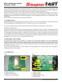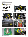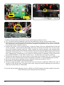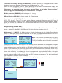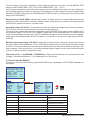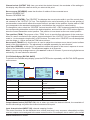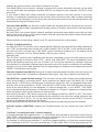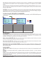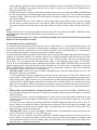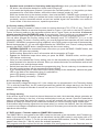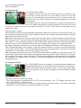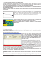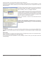
1
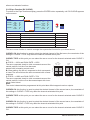
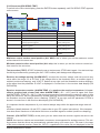
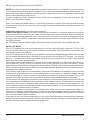
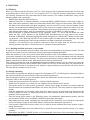
33300 RF Module M-G1 HoTT SD mc-19/19s and mc-22s CONTENT: 1. Introduction..............................................................................................................01 2. Preparing the systems.............................................................................................01 3. Connection...................................................................................................01 4. Assembly...................................................................................................02 5. General Note..............................................................................................................04 5.1. Transmitter Display (TX Display)................................................................................04 5.2. Receiver Display.........................................................................................................06 5.2.1. Receiver Data View (RX DATAVIEW).........................................................................06 5.2.2. Servo Data (RX SERVO)............................................................................................07 5.2.3. Failsafe Setup (RX FAILSAFE)..................................................................................08 5.2.4. Mixer Setup (RX FREE MIXER - WING MIXER)......................................................10 5.2.5. Expo functions (RX CURVE)......................................................................................11 5.2.6. Servo test (RX SERVOTEST)....................................................................................12 6. Functions.....................................................................................................14 6.1. Binding.............................................................................................................14 6.1.1.Binding multiple receivers in one model...................................................................14 6.2. Range checking..........................................................................................................14 6.3. Fail Safe Function .......................................................................................................15 6.4. Country setting...........................................................................................................16 6.5. Low voltage warning..................................................................................................16 6.6. Range warning...........................................................................................................16 6.7. DATA socket...............................................................................................................16 6.8. Data storage...............................................................................................................17 6.9. Earphone socket.........................................................................................................17 7. Firmware Updates....................................................................................................18 7.1. Update process..........................................................................................................18 8. Warranty....................................................................................................22 GRAUPNER GmbH & Co. KG – Postfach 1242 – 73230 Kirchheim/Teck – www.graupner.de Manual Module M-G1 Order-No. 33300 These operating instructions are part of this product. They contains important notes to the operation and handling. Please take this into consideration when you pass on the product to third parties. Neglect of the operating instructions and the safety instructions lead to expiring the warranty. Graupner constantly work on the advancement of all remote control systems; changes of the scope of delivery in form, technology and equipment we must reserve ourselves therefore. Please have understanding for the fact that from data and illustrations of this operating instructions no requirements can be derived. Please keep these instructions for further reference! 1. INTRODUCTION Many thanks for purchasing the Graupner M-G1 HoTT 2.4 module. This module is a direct replacement for the standard RF module fitted to your mc-19/mc-19s and mc-22s transmitters. Please read right through these instructions before you attempt to install and use the system. Installation requirements We recommend that you have the module installed by a Graupner Service Centre. It is possible for the modeller to carry out the conversion himself provided that he has a certain amount of manual skill, but the transmitter’s firmware needs to be updated for the first time in order to integrate the telemetry display (mc-19s/iFS and mc-22s/iFS only), and this can only be carried out by the Graupner Service Centre Germany. Please note that we cannot offer a guarantee for all failures which have been caused by incorrect installation, if you carry out the conversion work yourself. 2. PREPARING THE SYSTEM First remove your previous RF module. For details of this procedure please refer to the appropriate chapter in the operating instructions supplied with your radio control system. If you have previously used a 35 MHz system, you will also need to replace the telescopic aerial with the Graupner HoTT aerial supplied in the set. This requires the use of the aerial conversion kit for tray-mounted transmitters, Order No. 23049 - see Figs. 1 to 5. If you have previously used a 2.4 GHz system such as Graupner iFS, all you need to do is unplug the existing aerial from the module. 3. CONNECTION Front Rear 3 6 7 5 1 2 1. Antenna terminal 2. Module terminal 4-pin 3. Earphone socket (stereo) 01 4 3 4. USB 1 socket 5. USB 2 socket 6. BIND/RANGE button 7. Status-LED‘s Manual Module M-G1 33300 4. ASSEMBLY: 1 4 X 1 3 4 2 Fig. 2 Fig. 1 Fig. 3 Fig. 4 Manual Module M-G1 33300 Fig. 5 Fig. 6 Fig. 7 Fig. 8 02 2 1 Fig. 9 Fig. 10 Fig. 11 1. Position the aerial lead and the blue four-pin module plug as shown in Fig. 6. 2. Fig. 7 shows the white rectangular socket for the module plug, and the circular aerial socket. 3. Press the four-pin module plug into the socket on the module using light pressure. The connector system is polarised: note the lateral lugs. Ensure that it engages fully (arrows), so that there is no chance of it working loose in operation (Fig. 8). 4. Position the module in the mounting frame. Locate the loops at the top (marked black), fit the M3 screws (supplied - marked yellow) and tighten them fully to secure the module (Fig. 9). The 14-pin plug of the optional interface cable No. 33304 (needed for internal telemetry, only available after transmitter update) which terminates the interface lead should now be plugged into the socket on the transmitter circuit board (Fig. 9 - 1). The connector system is polarised: note the lateral lugs. Ensure that it engages fully, so that there is no chance of it working loose in operation. Finally connect the plug marked “MODULE” to the USB 1 socket (Fig. 9 - 2); the brown wire must be at the top. 5. Connect the aerial plug to the aerial socket on the module circuit board (Fig. 10). It is best to use tweezers for this: push the plug into place as straight as possible, to avoid damaging the contacts. 6. Secure the aerial lead by applying a drop of adhesive at the point marked in Fig. 11. 7. Now attach the back panel to the transmitter again. 8. Finally go to the transmitter „basic setup model“ menu and choose „modulation“ PPM 18 (for max. 9 servos) or PPM 24 (for max. 12 servos). Also when using the channel mapping with more than 9 channels choose PPM 24. JOB DONE! To use the internal display telemetry the mc-19s/iFS mc-22s/iFS needs a first-time update of the transmitter firmware by the Graupner Service Germany! 03 Manual Module M-G1 33300 5. GENERAL NOTE When switching on or adjusting the radio control system it is essential to keep the transmitter aerial at least 15 cm away from the receiver aerials at all times. If the transmitter aerial is too close to the receiver aerials, the receiver will be overloaded, causing the red LED on the receiver to light up. The transmitter responds by emitting a beep once every second; the red LED also goes out. The radio control system is now in Fail-Safe mode. If this should occur, simply increase the distance between the aerials until the audible warning signal ceases, and the red LED on the transmitter lights up again; at the same time the red LED on the receiver should go out. Please note: if you wish to switch the transmitter on again just after switching it off, please wait at least five seconds to ensure that the transmitter has time to shut down completely. If you neglect to do this, there will be no connection between transmitter and receiver: you will hear a beep repeated about once per second, and at the same time the red LED on the transmitter will go out, and the LED on the receiver will flash red. 5.1. Transmitter Display (TX-Display) The telemetry can be programmed directly on all HoTT transmitters whose telemetry menu is integrated directly into the transmitter’s screen (this is possible with most models after a firmware update). If this update is not carried out, programming is only possible using the SMART-BOX. The SMART-BOX, Order No. 33700, must be used for programming if you are using any of the following transmitters: mx-22, Order No. 4801 / 4802, mc-19, Order No. 4821, mc-22, Order No. 4818 and mc-18, Order No. 4835. The Smart Box is used instead of the interface cable connected to the USB1 socket.The following instructions describe the method using the SMART-BOX; the table below shows variations which apply to the Telemetry menu for the various models of transmitter: SMART-BOX mx-12/16/20/32 HoTT mc-19/mc-22/mc-24/mx-24 HoTT ENTER ENTER ESC CLEAR INC scroll: value: scroll: push Rotary + value: Rotary DEC scroll: value: scroll: push Rotary + value: Rotary INC+DEC SET push Rotary TX: SD-card log ON A: 11.3 V M: 11.4V m: 11.2V VA R I O T O N E : ON RANGE TEST : OFF 90s RX BIND : BIND ALARM VOLT : 9.3V COUNTRY :GENERAL MULTIC1: 00 MULTIC2: 00 The TX screen appears when - the SMART-BOX is connected to the DATA socket and the first line „SETTING AND DATAVIEW“ is activated by pressing the ENTER button or - transmitters with integrated telemetry: the menu item „telemetry“ is selected press the Rotary Display Description Setup SD-card log Shows the saving process on the SD card ON /OFF automatic A = TX VOLT Current operating voltage (V) - M = MAXIMUM VOLT Maximum operating voltage (since the last power on - V) - m = MINIMUM VOLT Minimum operating voltage (since the last power on - V) - RX BIND Binding the receiver BINDING ALARM VOLT voltage setup for transmitter low voltage warning beep 4 – 15 V in steps of 0.5 V Factory setting 9.3 V COUNTRY Country setting GENERAL / FRANCE RANGE TEST indicates if the range test is engaged, the remaining time also appears OFF / ON MULTIC 1 / 2 Multichannel 1 or 2 (Nautic-Expert-Module Order No. 4108) Channel select 1-X (+ PERIOD: 20 msec, CH OUTPUT TYPE: SAME) Manual Module M-G1 33300 04 Transmitter low-voltage warning (ALARM VOLT): you can adjust the low voltage threshold at which the alarm (continuous beeping) is triggered; the available range is 4 - 15 V. When the alarm is triggered, “VOLT-E” flashes at top right in the SMART-BOX transmitter display, and the parameters ACTION VOLT and ALARM VOLT are displayed in inverse form. Please note: the transmitter’s own low-voltage warning (beep), as set in the “General settings” menu, is triggered independently of the value set under TX-Display! Binding a receiver (RX BIND): refer to chapter 6.1. Binding SD card function (SD SAVE): refer to chapter 6.8. Data storage Country selection (COUNTRY): The Country setting is present in order to cater for various directives (FCC, ETSI, IC etc.). The HoTT 2.4 radio system features a restricted frequency band for France. If you wish to use the RC system in France, the country setting on the transmitter must be set to “France” mode, as described. It is essential not to use the Universal/EUROPE mode. Factory setting is GENERAL. See also point 6.4. Range checking (RANGE TEST): switches the range test on or off, the remaining time is displayed. The display also works if the range check is started with the BIND / RANGE button on the transmitter. See also point 6.2. Multichannel 1 / 2 (MULTIC 1 / 2: Multi-channel function for the use with the Nautic-Expert-Module order no. 4108. Up to 2 multi-channel channels can be used, the appropriate channels must be set in the display under MultiC. If no Nautic module is used, set MULTIC to 00. RX SERVO OUTPUT CH: REVERSE : CENTER : TRIM : TRAVEL: TRAVEL+ : PERIOD : <> 01 ON 1500usec -000usec 100% 100% 20msec RX SERVO TEST < ALL-MAX : 2000usec ALL-MIN : 1000usec TEST : STOP ALARM VOLT : 3.8V ALARM TEMP+ : 70°C ALARM TEMP- : 10°C CH OUTPUT TYPE: SAME Note: The cycle time (PERIOD) must be set to 20 msec, the channel sequence (CH OUTPUT TYPE) to SAME so that the function is activated! Parameters which have different options in the Settings column of the table can be adjusted using the SMART-BOX. If there are no options, the screen simply displays the parameter data. If you wish to carry out an adjustment, you must use the INC or DEC buttons above the screen to select the desired parameter (e.g. ALARM VOLT) by moving the arrow cursor (INC moves the cursor down, DEC moves it up). Simultaneously pressing the INC and DEC buttons switches the parameter to be adjusted to inverse video (white on black); this indicates that it can be programmed: pressing the INC button at this point increases the value, pressing the DEC button reduces the value. When the adjustment is complete, save the selected setting by pressing the INC and DEC buttons simultaneously; the dark background now disappears in order to confi rm this action. Please note: the labeling of the arrows of the following displays corresponds the top buttons on the SMART-BOX. TX: SD-card log ON A: 11.3 VM: 11.4V m: 11.2V VA R I O T O N E : ON RANGE TEST : OFF 90s RX BIND : BIND ALARM VOLT : 9.3V COUNTRY :GENERAL MULTIC1: 00 MULTIC2: 00 INC + DEC TX: SD-card log ON A: 11.3 VM: 11.4V m: 11.2V VA R I O T O N E : ON RANGE TEST : OFF 90s RX BIND : BIND ALARM VOLT : 9.3V COUNTRY :GENERAL MULTIC1: 00 MULTIC2: 00 INC DEC ENTER ESC RX DISPLAY 05 Manual Module M-G1 33300 5.2. RECEIVER DISPLAY 5.2.1 Receiver Data View (RX DATAVIEW) If you wish to switch to the receiver data display, press the ENTER button repeatedly until RX DATAVIEW appears on the screen. Please note: menus 3.2.1 to 3.2.6 can only be selected when the receiver is RX DATAVIEW > S-QUA 100% S-dBm -49dBm switched on. When you switch the receiver on, it may take a few seconds befoS-STR 065% R-TEM. +30°C L PACK TIME 00005msec re the receiver display becomes active and can be selected: > symbol appears R-VOLT : 05.9V at the top right corner of the transmitter display (TX). LR-VOLT : 05.8V There may be a slight delay in the screen’s response to inputs using the top SENSOR1 : 00.0V 00°C SENSOR2 : 00.0V 00°C buttons, since all the settings are transmitted directly to the receiver by wireless means. In the receiver data view display settings can not be made. Display Description Setup S-QUA Signal quality in % - S-dBm Receive performance in dBm - S-STR Signal strenght in % - R-TEM Receiver temperature in °C - L PACK TIME indicates the duration of signal loss of the longest data packet du- ring transmission from transmitter to receiver; stated in msec R-VOLT Actual receiver operating voltage in Volt - L.R-VOLT Minimum receiver operating voltage since it was last switched on; stated in Volt - Sensor 1 the values of the optional telemetry sensor 1 in Volt and °C - Sensor 2 the values of the optional telemetry sensor 2 in Volt and °C - Signal quallity (S-QUA): shows the signal quality in % Receive performance (S-dBm): the receive performance is sent “live” to the SMART-BOX via the receiver’s downlink channel. Note: the receive performance is shown as a negative value, i.e. a value approaching zero is the maximum (= best reception); the lower the value falls, the worse the receive performance. This value is particularly important during the range-check procedure carried out before flying the model. Please read the corresponding section in the RC system instructions relating to range-checking. Carry out a range-check before every flight, simulating all servo movements which will occur in flight: the range must be at least 50 m on the ground when the transmitter is set to range-check mode; to guarantee safe flying, the value displayed under S-dBm in the DATAVIEW display should be at least -80 dBm. If the value is lower (e.g. -85 dBm) you should not even consider flying your model: check the receiver installation and the power supply systems in your model and radio control system. When operating your model this value should not fall below -90 dBm. If it does, you should reduce the distance between yourself and the model. However, under normal circumstances the audible range warning (see below) will be triggered before the value falls to this level, in order to ensure safe operations. Signal strenght (S-STR): indicates the signal strenght in %. An audible range warning (continuous beeping at one-second intervals) is always emitted as soon as the receiver signal in the downlink channel falls to the pre-set threshold. Since the transmitter has a much higher transmitting power than the receiver, it is still possible to operate the model safely, but in the interests of security you should always reduce the distance to the model until the audible warning stops. Receiver temperature (R-TEMP): it is important that the temperature of your receiver always stays within the approved range under all flight conditions (ideally between 10 and 55°C; please refer to your RC system instructions). Manual Module M-G1 33300 06 The limit values for receiver temperature which trigger a warning can be set in the RX SERVO TEST display under ALARM TEMP+ (50 – 80°C) and ALARM TEMP- (-20 – +10°C). If the receiver temperature rises above the maximum value or falls below the minimum, the unit generates an audible warning (continuous beeping). At the same time all the Smartbox receiver displays show a flashing “TEMP.E” at top right, and the parameter R-TEM is shown in inverse form in the receiver data display (RX DATAVIEW). Data packets (L PACK TIME): indicates the duration of signal loss of the longest data packet during transmission from transmitter to receiver, stated in msec. In practice this equates to the longest period which the RC system has spent in fail-safe mode. Operating voltage (R-VOLT): it is essential to monitor the operating voltage of the receiver constantly. If it is too low, you must never launch your model or continue flying it. The receiver low voltage warning can be adjusted in the RX SERVO TEST display under ALARM VOLT; the available range is 3.0 to 6.0 Volt. If battery voltage falls to the threshold level, an audible signal (continuous beeping) is emitted, and “VOLT.E” flashes at top right in all the Smartbox receiver displays. At the same time the parameter R-VOLT is shown in inverse form in the receiver data display (RX DATAVIEW). Minimum operating voltage (L.R-VOLT): displays the lowest receiver operating voltage since the last time the receiver was switched on. If this voltage differs significantly from the actual operating voltage R-VOLT, it is likely that the servos are placing an excessive load on the receiver battery, resulting in voltage collapses. If this should occur, you should consider fitting a larger or more robust receiver battery in order to obtain maximum operating security. Telemetry sensor 1 / 2 (SENSOR 1 / SENSOR 2): if these optional sensors are connected, their data (Voltage / Volt and temperature / °C) is displayed live on the screen. 5.2.2 Servo data (RX SERVO) To switch to the servo data display, press the ENTER button repeatedly until RX SERVO appears on the screen. RX DATAVIEW > S-QUA 100% S-dBm -49dBm S-STR 065% R-TEM. +30°C L PACK TIME 00005msec R-VOLT : 05.9V LR-VOLT : 05.8V SENSOR1 : 00.0V 00°C SENSOR2 : 00.0V 00°C ENTER ESC RX SERVO OUTPUT CH: REVERSE : CENTER : TRIM : TRAVEL: TRAVEL+ : PERIOD : <> 01 ON 1500usec -000usec 100% 100% 20msec INC + DEC INC + DEC RX SERVO OUTPUT CH: REVERSE : CENTER : TRIM : TRAVEL: TRAVEL+ : PERIOD : <> 01 ON 1500usec -000usec 100% 100% 20msec INC DEC Display Description Setup OUTPUT CH Channel select 1 – X, depends on the connected receiver REVERSE Servo reverse OFF / ON CENTER Neutral point in usec. If active (highlighted), according to transmitter control position TRIM Trim position in usec. -120 – 120 usec TRAVEL- Servo travel in %, negativ 30 – 150% TRAVEL+ Servo travel in %, positiv 30 – 150% PERIOD Cycle time in msec. 10 or 20 msec 07 Manual Module M-G1 33300 Channel select (OUTPUT CH): here you select the desired channel; the remainder of the settings in this display only affect the channel which you select at this point. Servo reverse (REVERSE): sests the direction of rotation of the connected servo Normal: REVERSE OFF Reverse: REVERSE ON Servo centre (CENTER): The “CENTRE” line displays the current pulse width in μs of the control channel selected in the “OUTPUT CH” line. The displayed value varies according to the current position of the transmitter control which affects this control channel, and also its trim position. A pulse width of 1500 μs corresponds to the standard centre position, and therefore the usual servo centre setting. To change this value, select the “CENTRE” line and touch the INC + DEC buttons simultanously. Move the corresponding transmitter control to the desired position, and touch the INC + DEC buttons again to store the current transmitter control position. This position is now stored as the new neutral position. Trim position (TRIM): The purpose of the “TRIM” line is to provide fine adjustment of the neutral position of a servo connected to the control channel selected in the “OUTPUT CH” line. Adjustments are made in 1 μs increments using the INC or DEC buttons. The value in the “CENTRE” line can be adjusted over the range +/- 120 μs around the TRIM value set here. Servo travel (TRAVEL +/-): this function is used to adjust the maximum servo travel (control surface travel) of the connected servo. The adjustment is available separately for each direction Cycle time (PERIOD): at this point it is possible to define the speed of the servos’ response to movements of the transmitter controls. This adjustment applies to all channels. Note: if you are using analogue servos, you must set a value of 20 msec. If you are using digital servos exclusively, 10 msec should be selected. 5.2.3 Failsafe Setup (RX FAIL SAFE) To switch to the Failsafe setup display, press the ENTER button repeatedly until RX FAIL SAFE appears on the screen. ENTER ESC RX FAIL SAFE OUTPUT CH: INPUT CH : MODE : F.S.Pos. : DELAY : FAIL SAFE ALL POSITION : <> 01 01 FAI SAFE 1400usec 0.75sec : NO 1500usec INC + DEC INC + DEC RX FAIL SAFE OUTPUT CH: INPUT CH : MODE : F.S.Pos. : DELAY : FAIL SAFE ALL POSITION : <> 01 01 FAI SAFE 1400usec 0.75sec : NO 1500usec INC DEC Display Description Setup OUTPUT CH Output channel select 1 – X, depends on the connected receiver INPUT CH Input channel select 1 – 16 MODE Fail-safe Mode Fail Safe / Hold / Off Factory setting Hold F.S. Pos. Failsafe Position 1000 - 2000 usec DELAY Failsafe response time 0.25, 0.50, 0.75, 1.00sec Factory setting 0.75 sec. FAIL SAFE ALL Stores fail-safe positions for all control channels NO / SAVE POSITION Failsafe position 1000 - 2000 usec Output channel select (OUTPUT CH): this is where you select the desired channel; the remainder of the fail-safe settings only affect the channel selected at this point. Input channel select (INPUT CH): channel mapping function The control functions can be distributed over several receivers in any sequence; alternatively multiple receiver outputs can be assigned to the same control function. For example, this is useful if your aircraft Manual Module M-G1 33300 08 features two servos acting on each aileron instead of only one. The SMART-BOX can be used to manage a maximum of sixteen transmitter channels. At this point you can define how the transmitter channels (INPUT) are assigned to the channels (OUTPUT) of the receiver(s). If your model is fitted with multiple receivers, the Master receiver is the last receiver to be bound. However, in subsequent operations only the receiver which was bound last is able to make a telemetry connection to the transmitter. On the other hand, this also means that only the last bound receiver can be addressed using the Telemetry menu. Fail-safe mode (MODE): this function is used to select the fail-safe mode for the channel you have selected. You can select either a programmed fail-safe position (Fail Safe), hold-mode for the last position (HOLD) or OFF. But CAUTION: if the control signal is absent, analogue servos and many digital servos offer no resistance to the forces acting on the control surfaces, with the result that the model’s control surface positions are more or less quickly lost. Please read the corresponding chapter in the RC system instructions on this subject. F.S.Pos. (Fail-Safe position): For each OUTPUT CH (receiver servo socket) activate (highlight) the value field by briefly pressing the INC + DEC simutanously, then use the INC or DEC buttons in the “F.S.POS.” line to set the servo position which the servo is to take up in “FAIL-SAFE” mode if interference should occur. The setting can be entered in increments of 10 μs. Default setting: 1500 μs (servo centre). Important note: The “F.S.POS.” function is also significant if the receiver is switched on, but is (not yet) receiving a valid signal; this applies to all three modes “OFF”, “HOLD” and “FAILSAFE”: The servo immediately runs to the Fail-Safe position previously set in the “Position” line. This can be exploited, for example, to prevent the operation of a retractable undercarriage or similar function if the receiver is switched on accidentally. However, during normal model operations the corresponding servo behaves in accordance with the set “MODE” if interference should strike. Fail-safe response time (DELAY): this point is used to select the delay time after which the servos run to their selected position if interference affects the radio signal. This value is applied to all channels. FAIL SAFE ALL (global fail-safe setting): This sub-menu can be used to define the Fail-Safe position of the servos simply by “pressing a button”; and is simple to use: Move to the “FAIL-SAFE ALL” line and press the INC + DEC buttons simultanously to activate the value field; “NO” is highlighted (black background). Now set the parameter to “SAVE” using the INC or DEC button. Use the transmitter controls to move all the servos which you have assigned - or intend to assign later - in the “MODE - FAIL-SAFE” line, to the desired fail-safe positions. In the extreme bottom line “Position” displays the current position of the transmitter control for the channel you have just set. After touching the INC + DEC buttons once more, the display reverts from “SAVE” to “NO”. This indicates that the position of all the servos affected by the procedure have now been stored, and have also been adopted in the “F.S.Pos.” line. At the same time the position for the current OUTPUT CH (servo socket) is immediately displayed on the screen. Switch the transmitter off, and check the Fail-Safe positions by observing the servo movements. Fail-safe position (POSITION): displays the Fail-Safe position for the channel set under OUTPUT CH. “Fail-Safe” in combination with “channel mapping” It is clearly desirable that mapped servos - i.e. servos which are controlled by a common control channel (INPUT CH) - should respond in the same way when interference occurs, so the corresponding settings of the INPUT CH determine the behaviour of mapped servos. For example, if receiver servo sockets 6, 7 and 8 are mapped together, i.e. if the same control channel “04” is assigned to OUTPUT CH (servo sockets) 06, 07 and 08 then INPUT CH 04 determines the Fail- 09 Manual Module M-G1 33300 Safe behaviour of the three servos connected to control channel 4, regardless of the individual settings of the OUTPUT CH for INPUT CH 04. This also applies, for example, if it is mapped in turn to INPUT CH 01. In this case servo socket 04 would respond in accordance with the Fail-Safe settings for CH 01. In contrast, the response or delay time set in the “DELAY” line always applies uniformly to all channels which are set to “FAIL-SAFE”. CAUTION: if the receiver is switched on and you call up the fail-safe function again using the programming button on the transmitter, any settings previously programmed in the FAIL SAFE display using the SMART-BOX will be lost, including the channel assignment (INPUT CH). 5.2.4 Mixer Setup (RX FREE MIXER / RX WING MIXER) To switch to the Mixer setup display, press the ENTER button repeatedly until RX FREE MIXER appears on the screen. ENTER ESC RX FREE MIXER <> MODE : 1 MASTER CH : 08 SLAVE CH : 08 S-TRAVEL- : 100 S-TRAVEL+ : 100 RX WING MIXER TAIL TYPE : NORMAL INC + DEC INC + DEC RX FREE MIXER <> MODE : 1 MASTER CH : 08 SLAVE CH : 08 S-TRAVEL- : 100 S-TRAVEL+ : 100 RX WING MIXER TAIL TYPE : NORMAL Display Description Setup MODE Mode 1, 2, 3 MASTER CH Master channel 0, 1 – 8 SLAVE CH Slave channel 0, 1 – 8 SLAVE TRAVEL- Limit Servo travel, negative 0 – 150% SLAVE TRAVEL+ Limit Servo travel, positive 0 – 150% RX WING MIXER TAIL TYPE Tail type Normal, V-Tail, Elevon INC DEC RX FREE MIXER Mode (MODE): a total of up to three mixers can be used simultaneously, and the MODE function is used to switch between mixer 1, mixer 2 and mixer 3 for the purpose of adjustment. The remainder of the settings in this display only affect the mixer selected at this point. Master channel (MASTER CH): here you set the main channel (primary control function); the slave channel is mixed into the channel you select at this point. Sub-channel (SLAVE CH): subsidiary channel coupled to the main channel; the sub-channel is mixed into the main channel to the extent defined by the value you set. Sub-channel servo travel (SLAVE TRAVEL +/-): this point is used to adjust the maximum control surface travel of the servo connected to the sub-channel; the adjustment is carried out separately for both directions (EPA). RX WING MIXER Tail type (TAIL TYPE): at this point you can select pre-set mixer functions for the appropriate model type NORMAL: conventional model aircraft - separate rudder and elevator at the tail - no mixer functions activated V-TAIL: For this model type the control functions elevator and rudder are linked together in such a way that each of the two control surfaces - actuated by a separate servos - carries out superimposed elevator and rudder functions. ELEVON (delta / flying wing models): The servos connected to outputs 2 and 3 assume superimposed Manual Module M-G1 33300 10 aileron and elevator functions. 5.2.5 Expo Functios (RX CURVE) To switch to the Expo functions display, press the ENTER button repeatedly until RX CURVE appears on the screen. ENTER ESC RX CURVE CURVE 1 CH : TYPE : CURVE 2 CH : TYPE : CURVE 3 CH : TYPE: 01 B 02 B 03 B <> INC + DEC RX CURVE CURVE 1 CH : TYPE : CURVE 2 CH : TYPE : CURVE 3 CH : TYPE: 01 B 02 B 03 B <> INC DEC INC + DEC Display Description Setup CURVE1 CH Channel number, servo curve 1 1–8 CURVE1 TYPE Servo curve 1 Type A, B, C CURVE2 CH Channel number, servo curve 2 1–8 CURVE2 TYPE Servo curve 2 Type A, B, C CURVE3 CH Channel number, servo curve 3 1–8 CURVE3 TYPE Servo curve 3 Type A, B, C The servo curve function is used to manage the exponential function for up to three servos. CURVE1 CH: this function is used to select the desired channel of the first servo; the remainder of the settings in CURVE 1 TYPE only affect the channel selected at this point Servoweg +100% 0 Servoweg +100% 0 –100% –100% –100% Servoweg +100% 0 CURVE1 TYPE: at this point you can select the servo curve for the channel selected under CURVE 1 CH. TYP C TYP A A: EXPO = -100% and DUAL RATE = 125% Expo = +100% Expo = –100% TYP B DR = 125% DR = 70% linear The servo responds slowly to stick movements around the neutral position, but the curve becomes steeper with increasing control travel. B: linear setting: the servo’s response to stick movements is linear The servo follows the stick movement with a linear response. –100% 0 +100% –100% 0 +100% –100% 0 +100% C: EXPO = +100% and DUAL RATE = 70% Geberweg Geberweg Geberweg The servo responds slowly to stick movements around the neutral position, but the curve becomes steeper with increasing control travel. Note: The control characteristics programmed at this point also affect mapped receiver outputs. CURVE2 CH: this function is used to select the desired channel of the second servo; the remainder of the settings in CURVE 2 TYPE only affect the channel selected at this point CURVE2 TYPE: at this point you can select the servo curve for the channel selected under CURVE 2 CH. CURVE3 CH: this function is used to select the desired channel of the second servo; the remainder of the settings in CURVE 3 TYPE only affect the channel selected at this point CURVE3 TYPE: at this point you can select the servo curve for the channel selected under CURVE 3 CH. 11 Manual Module M-G1 33300 5.2.6 Servo test (RX SERVO TEST) To switch to the Servo test display, press the ENTER button repeatedly until RX SERVO TEST appears on the screen ENTER ESC RX SERVO TEST < ALL-MAX : 2000usec ALL-MIN : 1000usec TEST : STOP ALARM VOLT : 3.8V ALARM TEMP+ : 70°C ALARM TEMP- : 10°C CH OUTPUT TYPE: ONCE INC + DEC INC + DEC RX SERVO TEST < ALL-MAX : 2000usec ALL-MIN : 1000usec TEST : STOP ALARM VOLT : 3.8V ALARM TEMP+ : 70°C ALARM TEMP- : 10°C CH OUTPUT TYPE: ONCE INC DEC Display-Anzeige Erläuterung Einstellungen ALL MAX Maximum control surface travel position for all servos 1500 – 2000 usec ALL Min Minimum control surface travel position for all servos 1000 – 1500 usec TEST Test procedure START / STOP ALARM VOLT Displays the set voltage at which the low voltage warning signal is triggered 3.0 – 6.0 V Factory setting 3.8 V ALARM TEMP+ Displays the upper limit value at which the warning signal is triggered 50 – 80° C Factory setting 70°C ALARM TEMP- Displays the lower limit value at which the warning signal is triggered -20 – +10° C Factory setting -10°C CH OUTPUT TYPE Channel sequence ONCE / SAME / SUMI / SUMO Maximum control surface travel position (ALL MAX): this is where you set the maximum control surface travel for the servo test Minimum control surface travel position (ALL min): this is where you set the minimum control surface travel for the servo test Test procedure (TEST): START initiates the servo test process; STOP halts it again. You start and stop the test by simultaneously pressing the INC / DEC buttons (dark background disappears) Receiver low voltage warning (ALARM VOLT): monitors the receiver voltage, and can be set to any value within the range 3.0 to 6.0 Volt. If the voltage falls to the threshold value, an audible signal is emitted (continuous beeping), and “VOLT.E” flashes at top right in all the Smartbox’s receiver displays; at the same time the parameter R-VOLT is displayed in inverse form in the receiver data display (RX DATAVIEW). Receiver temperature monitor (ALARM TEMP +/-): monitors the receiver temperature. It is possible to program both a lower limit value ALARM TEMP- (-20 – +10°C) and an upper limit value ALARM TEMP+ TEMP (50 – 80°C). If the receiver temperature rises above the maximum value or falls below the minimum, the unit generates an audible warning (continuous beeping). At the same time all the Smartbox receiver displays show a flashing “TEMP.E” at top right, and the parameter R-TEM is shown in inverse form in the receiver data display (RX DATAVIEW). It is important that the temperature of your receiver always stays within the approved range under all flight conditions (ideally between 10 and 55°C; please refer to your RC system instructions). If the temperature rises above maximum or falls below minimum an audible signal is emitted (continuous beeping) Channel- (CH OUTPUT TYPE): at this point you can select how the receiver signals are sent to the outputs. ONCE: the receiver outputs are transmitted in sequence: recommended for analogue servos. This setting ensures that the servos are automatically operated using a 20 msec cycle - 30 msec in the case of the twelve-channel receiver (Order No. 33512) - regardless of the value set and displayed in the RX Manual Module M-G1 33300 12 SERVO display under the menu point ‘PERIOD’. SAME: the receiver outputs are transmitted in parallel blocks of four, i.e. channels 1 to 4 and channels 5 to 8 receive the transmitter signal simultaneously in each case: recommended for digital servos. It is particularly useful where multiple servos are used for a particular function (e.g. ailerons), so that all the servos move absolutely synchronously. It is also possible to connect analogue servos; in this case you must set 20 ms in the menu point ‘PERIOD’ in the RX SERVO display. Note: if you select the SAME setting, it is especially important to install a high-capacity receiver power supply system, as up to four servos are almost always working simultaneously, placing a greater load on the battery. SUMI (Sum signal Input): Input for satellite receiver SUMO (Sum signal output): the receiver outputs are transmitted in sequence, whereby the highest channel transmits the sum signal; this signal is required by certain optional devices. With this setting the servos are automatically operated using a 20 msec cycle - 30 msec in the case of the twelve-channel receiver (Order No. 33512) - regardless of the value set and shown in the menu point ‘PERIOD’ of the RX SERVO display. Ex: V-Stabiliser, teacher-student system, Microbeast, flight simulator and output satellite receiver SATELLITE MODE Two HoTT receivers are inter-connected using a three-core connecting lead (Order No. 33700.1 (300 mm) or 33700.2 (100 mm) by the highest-numbered servo sockets. For more details on this please visit www.graupner.de on the Internet. The HoTT receiver which is confi gured as SUMO (see below) is designated the satellite receiver, and all its channels are transmitted in the form of a sum signal to the second HoTT receiver - the primary receiver - if reception should fail; the primary receiver must be programmed as “SUMI”. Note that the signal only ever moves towards SUMI. The receiver outputs are addressed in sequence at a frame rate of 20 ms (30 ms with the GR-24 receiver, Order No. 33512), even if you have set 10 ms in the “PERIOD” line of the “RX SERVO” screen page. However, if the receiver programmed as the satellite (SUMO) suffers signal reception failure, the servos connected to that receiver take up the Fail-Safe positions programmed in the satellite receiver, regardless of the primary receiver. This receiver confi guration is recommended in particular circumstances: for example, if one of the two receivers has to be installed in an unfavourable position in the model, or if there is a danger that the received signal will be weak in certain fl ight attitudes, perhaps due to a turbine, carbon fi bre in the airframe, or a similar problem, with the result that sporadic range problems might be expected. For this reason it is essential to connect the most important control functions to the primary receiver (the one programmed as SUMI), so that interference to the satellite receiver (SUMO) does not cause the model to go out of control. Telemetry data, such as the voltage of the airborne power supply, are only sent to the transmitter by the satellite receiver (confi gured as SUMO), i.e. all telemetry sensors must be connected to the satellite receiver (SUMO). Each receiver should be connected to the shared power supply using its own power lead. If high currents can be expected, duplicated power connections are recommended. However, if each of the two receivers is to be powered by its own battery, then it is essential to withdraw the central (red) wire from one of the two satellite lead connectors. If you wish to carry out further programming, such as the Fail-Safe settings, disconnect the three-core satellite connection between the two receivers, and switch on just the receiver you wish to address. Note that you may also need to change the binding sequence. 13 Manual Module M-G1 33300 6. FUNCTIONS 6.1. Binding When you wish to use the Graupner HoTT 2.4 GHz receiver with a particular transmitter, the first step must always be to “bind” the unit to “its” Graupner HoTT 2.4 GHz RF module (transmitter). However, the “binding” procedure is only required once for each receiver / RF module combination. Carry out the following steps when necessary: • Switch the transmitter and receiver on. • Without Smart-Box or internal telemetry: Locate the BIND / RANGE button on the back of the module, and hold it pressed in while you press and hold the SET button on the receiver. Both LEDs on the back of the transmitter now glow constantly, and the red LED on the receiver flashes. Under normal circumstances the flashing red LED on the receiver will cease to flash and switch to a constant green within about ten seconds. This indicates that the binding process is complete. You can now release both buttons, and your transmitter / receiver combination is ready for use. • With Smart-Box or internal telemetry: At the Telemetry menu “TX” go to the RX BIND line, then press the INC + DEC buttons on the SMART-BOX simultaneously (or push rotary): the screen changes to BINDING, displayed highlighted (black background). Hold the SET button on the receiver pressed. If the flashing red LED on the receiver goes out within about ten seconds, the green LED glows constantly then the binding procedure has been completed successfully. • However, if the red LED on the receiver continues to flash for longer than ten seconds, then the binding process has failed. If this should occur, repeat the whole procedure. 6.1.1. Binding multiple receivers in one model If required, it is also possible to bind multiple receivers to the transmitter for a particular model. The first step is to bind each receiver individually using the procedure already described. When the system is in use, the receiver which was switched on first, is the Master receiver. Any telemetry sensors installed in the model must be connected to this unit, as only the Master receiver transmits sensor data using the downlink channel. The second and all further receivers operate in parallel with the Master receiver but in Slave mode, with the downlink channel switched off. The control functions can also be distributed amongst multiple receivers; this is carried out using the Channel Mapping function of the SMART-BOX (Order No. 33700). In the same way it is possible to assign one control function to multiple receiver outputs; a typical example would be the use of two servos for each aileron instead of only one, etc. 6.2. Range checking The method of checking the effective range of the Graupner HoTT 2.4 GHz system is described below. We recommend that you ask a friend to help you with this procedure. After binding the receiver to your transmitter, switch the transmitter and the receiver on, and wait until the green LED on the receiver lights up. • Install the bound receiver in the model in its final intended position. • Switch the RC system on, so that you can observe the movement of the servos. • Set up the model on a flat surface (pavement, closely mown grass or earth), and ensure that the receiver aerials are located at least fifteen cm above the ground. This may require a support for the model. • Hold the transmitter at hip-height, away from your body, but do not point the aerial directly at the model; instead turn and / or angle the aerial tip so that it stands vertical, and keep it there for the duration of the range check. • Start the range check mode in the Telemetry menu; the transmitter starts beeping evenly, and the red and green LEDs next to the BIND / RANGE button flash alternately. • Walk away from the model, operating the transmitter sticks constantly. If you detect an interruption in the link within a range of about fifty metres, stand still and attempt to reproduce it. • If the model is fitted with a motor, switch it on in order to check whether the power system is generating interference. • Continue to walk away from the model until you reach the point where perfect control is no longer possible. • Now press the BIND / RANGE button on the transmitter once more; this terminates range-check Manual Module M-G1 33300 14 mode manually, and the model should respond normally to control commands. If this does not occur with 100% reliability, the system should not be used. Contact your local Service Department of Graupner GmbH & Co. KG. • Range-check mode is usually terminated manually when the user presses the BIND / RANGE but ton, but it terminates automatically after about ninety seconds in any case. The red LED now glows constantly again, while the green LED either glows constantly or flashes continuously, according to the Country setting. • We recommend that you check effective radio range before every flight. While you are carrying out the check, simulate all the servo movements which will take place when the model is in flight. The ground range must always be at least fifty metres in order to ensure safe, reliable model control. Note: Range-check mode is usually terminated manually when the user presses the BIND / RANGE button, but it terminates automatically after about ninety seconds in any case. CAUTION: During normal operations (i. e. when controlling a model) never press and hold the programming button on the transmitter module! 6.3. Fail-Safe function (RX Failsafe) In its default state (as delivered) the receiver is set to “Hold” mode, i.e. if a fail-safe situation occurs, all the servos connected to it maintain the last position detected as valid. In this mode the red LED on the receiver lights up when interference occurs, and the red LED on the transmitter goes out. The transmitter also starts beeping about once per second as an audible warning. You can exploit the safety potential of the fail-safe option by at least programming the throttle channel to respond to a fail-safe situation: the throttle channel of an engine-powered model should be set to idle, the throttle channel of an electric-powered model to “stop”, and the throttle channel of a model helicopter to “Hold”. You can program the fail-safe function either in the Telemetry menu under “RX Failsafe” (5.2.3), or on the transmitter module: repeated brief presses of the BIND / RANGE button on the transmitter module cycle through the fail-safe modes (fail-safe on / off, hold-mode, or standard). Locate the BIND / RANGE button on the back of the module, and hold it pressed in while you switch the transmitter on. Release the button again once it is switched on. • Fail-Safe mode: when you press the BIND / RANGE button, the transmitter beeps once; the red and green LEDs glow constantly. It is now possible to program positions to which the servos will move in a Fail-Safe situation; this occurs after a “Hold” period of 0.75 seconds: move the corresponding transmitter controls (sticks, rotary knobs, INC / DEC buttons etc.) to the desired Fail-Safe positions SIMULTANEOUSLY, then hold the BIND / RANGE button pressed in for three to four seconds. When you release the button, both the red and green LEDs should light up constantly, and the transmitter should not emit an audible signal: the transmitter now reverts to Control mode. If this does not occur, repeat the procedure. • Hold mode (recommended for model helicopters): when you press the BIND / RANGE button, the transmitter beeps twice; the red LED lights up constantly, and the green LED goes out (factory default setting). If interference occurs, all servos programmed to “Hold” remain at the last position detected by the receiver as correct; this situation is maintained until such time as the receiver picks up a new, valid control signal. You can save your selection by holding the BIND / RANGE button pressed in for three to four seconds. When you release the button, both the red and green LEDs should light up constantly, and the transmitter should not emit an audible signal: the transmitter now reverts to Control mode. If this does not occur, repeat the procedure. • Fail-Safe OFF: when you press the BIND / RANGE button, the transmitter beeps three times; the green LED glows constantly, the red LED goes out. You can save your selection by holding the BIND / RANGE button pressed in for three to four seconds. When you release the button, both the red and green LEDs should light up constantly, and the transmitter should not emit an audible signal: the transmitter now reverts to Control mode. If this does not occur, repeat the procedure. 15 Manual Module M-G1 33300 • Standard mode (suitable for fixed-wing model aircraft only): when you press the BIND / RANGE button, the transmitter beeps four times; both LEDs are off. In this mode the throttle servo (channel 1) moves to the Fail-Safe position, i.e. the position you have programmed for a Fail-Safe situation, while all the other channels remain at “Hold”. Move the throttle stick to the desired position, then hold the BIND / RANGE button pressed in for three to four seconds. When you release the button, both the red and green LEDs should light up constantly, and the transmitter should not emit an audible signal: the transmitter now reverts to Control mode. If this does not occur, repeat the procedure. 6.4. Country setting (COUNTRY) The Country setting is present in order to cater for various directives (FCC, ETSI, IC etc.). The HoTT 2.4 radio system features a restricted frequency band for France. If you wish to use the RC system in France, the country setting on the transmitter must be set to “France” mode, as described. It is essential not to use the Universal/EUROPE mode. If you select the “France” setting on your transmitter, you MUST select it again every time you alter the Fail-Safe settings using the programming button. You can either program the Country setting in the Telemetry menu “TX COUNTRY” (5.1.) or on the transmitter module: To select a Country setting, you must first switch the transmitter off, then insert the (FRANCE / GENERAL) programming plug (supplied) in the DATA socket on the back of the transmitter. Switch the transmitter on: you can now toggle between the “GENERAL” and “France” settings by briefly pressing the BIND / RANGE button, always starting with the current setting. • GENERAL/EUROPE: the transmitter beeps once when you press the BIND / RANGE button, and the green LED lights up constantly. Default setting: approved for use in all countries with the exception of France. • France: the transmitter beeps twice when you press the BIND / RANGE button, and the green LED flashes continuously. • Once you have selected the Country setting, save it in the transmitter by holding the BIND / RANGE button pressed in for about three seconds. When you release the button, the transmitter emits a brief confirmation tune, and the beeps cease. • Switch the transmitter off, and remove the programming plug. Do not under any circumstances use the radio control system with the programming plug inserted! • If you subsequently wish to check the current Country setting for the transmitter, observe the green LED on the back of the transmitter when it is switched on: green LED glowing constantly = “GENERAL” green LED flashing constantly = “France” 6.5. Low voltage warning If the transmitter voltage falls below 8.0 V (the voltage can be programmed in the Telemetry display “TX” or with the Smart-Box), the RF module generates an audible low voltage warning in the form of a steady series of beeps at intervals of around one second. This occurs independently of the transmitter software. 6.6. Range warning If the receiver signal in the down-link channel becomes too weak, the transmitter always generates an audible range warning in the form of a beep emitted about once per second. Since the transmitter’s output is much higher than that of the receiver, you will still maintain full control of the model, but in the interests of safety you should fly the model back towards you until the warning signal ceases again. If the audible range warning signal does not cease when you reduce the distance, then the transmitter or receiver low voltage or temperature warning is active! In this case you must land the model and cease operations without delay. 6.7. DATA socket - Firmware update or SMART-BOX connection The SMART-BOX is connected to the USB1-socket on the back of the transmitter, also Firmware updates for the transmitter RF module can be transferred via the USB1-socket in conjunction with a PC running Windows XP, Vista or 7. For this you also require the USB interface, Order No. 7168.6, and the adapter lead, Order No. 7168.6A, which are available separately. The programs and files required for this are available from www.graupner.de in the Download area for Manual Module M-G1 33300 16 the corresponding products. See also chapter 7. 6.8. Data Storage micro-SD and micro-SDHC Any standard commercial micro-SD memory card with a capacity of up to 2 GB can be used, and also any micro-SDHC card of up to 32 GB. However, the manufacturer recommends the use of memory cards with capacities up to only 4 GB, as these are completely adequate in all normal circumstances. The memory cards for which the transmitter is intended are familiar from their use in digital cameras and mobile telephones. Place the card in the slot with the contacts facing to the outside, and push it in until it locks. Now, the transmitter can be switched on again. Data recording / saving Data storage on the SD card automatically starts after a telemetry connection of the receiver exists, assuming that a compatible memory card is installed in the card slot - and will stop automatically 2 seconds after the receiver was turned off. Note: After switching on the receiver a beep will sound after about 2 seconds and the display „SD card log“ changes to ON - Data recording starts. After switching off the receiver the beep will sound again after about 2 s and the display changes to OFF. Then switch off the transmitter so that the log data is stored. If you turn off the transmitter before the beep / display OFF appears, no log data is saved! By default, always the transmitter and receiver data (with integrated telemetry) or transmitter only (without integrated telemetry) are recorded. To log the connected sensor or receiver, go to Start Recording in the menu „Model Select“ of the Smart-Box and select the connected sensor - with built-in telemetry transmitters, turn the Rotary from the basic display to the right. After concluding a data save process you will find a folder entitled “LogData” on the memory card. This folder stores log files which are named according to the following scheme: 0001, 0002.bin etc. (sequential numbers) in the folder named “No-Name”. The data can subsequently be analysed on a compatible PC using the PC programs which can be found on the download page for the associated transmitter at www.graupner.de. 6.9. Earphone socket The “EARPHONE” socket is designed to accept standard earphones or headphones fitted with a 3.5 mm stereo barrel connector (not included). Signals associated with the Telemetry menu, such as the audible Vario output, are present at this socket in addition to the transmitter’s audible signals. The vario tones are activated as follows: - The Vario output can be switched ON or OFF via the transmitter in the „TX“ display under the menu item „VARIO TONE“ - select ON here. - Go to the menu „Model Select“ of smart box and select the connected sensor - with built-in telemetry transmitters, turn the Rotary from the basic display to the right. 17 Manual Module M-G1 33300 7. Firmware Update Graupner-HoTT Module M-G1 Firmware updates for the transmitter RF module can be transferred via the USB1-socket in conjunction with a PC running Windows XP, Vista or 7. For this you also require the USB interface, Order No. 7168.6, and the adapter lead, Order No. 7168.6A, which are available separately. The programs and files required for this are available from www.graupner.de in the Download area for the corresponding products. Install the Firmware Update Utility Graupner and the USB drivers on your computer. Check the system requirements! The first step is to cut through the central red wire in the adapter lead, Order No. 7168.6A, then connect the lead to the USB interface, Order No. 7168.6. This socket is also polarised; note the small chamfer on one edge. Never use force - the plug should engage easily and fully. BIND/RANGE button Insert the adapter lead in the USB 1 socket on the rear of the module, as shown in the photo. Take care to maintain correct polarity! The black (or brown) braid (-) is at the top, the white (or orange) braid (S) at the bottom. USB 1 socket 7.1. Update procedure Ensure that the adapter lead is configured as shown in the illustrations, and is connected correctly to the transmitter or receiver. Start the Graupner Firmware Update Utility. Under [COM Port Setup] select the correct COM port, i.e. the one to which the USB lead is connected. If you are not sure of this, press the button „Search“ and select in the pop-up window „Silicon Labs CP210x USB to UART Bridge“ and press „OK“. Baud Rate: 19200. Under [Interface Type] click on Signal 2:Vcc3:Gnd. Now click on the “Browse” button and select the folder containing the previously loaded firmware file ending in *.bin. If everything is correct, the file will appear in the corresponding window. The firmware files are encoded in product-specific form, i.e. if you accidentally select a file which does not match the product (e.g. transmitter update file instead of receiver file), then the pop-up window “Product code error” will appear, and you will not be able to start the update procedure. Press the “Program” button in the software. Wait briefly until you see movement in the progress bar. This may take up to five seconds, depending on the computer. Transmitter: press the BIND / RANGE button, and switch the transmitter on while you hold it pressed in. After a few seconds the Status screen displays the message “Found target device…”; you can now Manual Module M-G1 33300 18 release the button, and the firmware update process commences. If the device is not recognised, if the pop-up window “Target device ID not found” appears, or if the process fails before 100% is reached, you must restart the update procedure. Repeat all the steps as described above. The Status display and the Progress bar show the progress of the firmware update. The update is completed when the message “Complete…100%” or “Complete!!” appears. During the update process both LEDs on the transmitter glow constantly. When it is complete, the red LED goes out and you will hear a brief confirmation melody. Both LEDs on the receiver also light up; when the process is complete, the green LED goes out, and the red LED starts flashing. Switch your transmitter / receiver off, and disconnect the adapter lead. Caution: after completing an update process, you must initialise the device before using it, i.e. reset it to the factory default values. Initialisation: To initialise the transmitter, or to reset it to the factory default settings, press and hold the BIND / RANGE button on the module while you switch the transmitter on, then release the BIND / RANGE button again. Please note: When initialisation is complete, the transmitter will be in Fail-Safe set-up mode. You can therefore immediately continue by programming your fail-safe settings. If you previously set your transmitter’s Country setting to “France” mode, you must also re-enter the Country setting. 19 Manual Module M-G1 33300 Konformitätserklärung gemäß dem Gesetz über Funkanlagen und Telekomunikationsendeinrichtungen (FTEG) und der Richtlinie 1999/5/EG (R&TTE) Declaration of Conformity in accordiance with the Radio and Telecomunikations Terminal Equipment Act (FTEG) and Directive 1999/5/EG (R&TTE) Graupner GmbH & Co. KG Henriettenstraße 94-96 D-73230 Kirchheim/Teck declares that the product Module M-G1 HoTT - No. 33300 Module mx-16 HoTT - No. 33301 Module M-G2 HoTT - No. 33302 Geräteklasse: 2 erklärt, dass das Produkt: Equipment class den grundlegenden Anforderungen des § 3 und den übrigen einschlägigen Bestimmungen des FTEG (Artikel 3 der R&TTE) entspricht. complies with the essential requirements of § 3 and the other relevant provisions of the FTEG (Article 3 of the R&TTE Directive). Angewendete harmonisierte Normen: Harmonised standards applied EN 60950:2006 Gesundheit und Sicherheit gemäß § 3 (1) 1. (Artikel 3 (1)a)) Health and safety requirements pursuant to § 3 (1) 1. (Article 3 (1) a)) EN 301 489-1 V1.7.1 EN 301 489-3 V1.4.1 Schutzanforderungen in Bezug auf elektromagnetische Verträglichkeit § 3 (1) 2, Artikel 3 (1) b)) Protection requirement concernig electromagnetic compatibility § 3 (1) 2, Artikel 3 (1) b)) EN 300 328 V1.7.1 Maßnahmen zur effizienten Nutzung des Frequenzspektrums § 3 (2) (Artikel 3 (2)) Measures for the efficient use of the radio frequency spectrum § 3 (2) (Article 3 (2)) Kirchheim, 06. Juni 2011 Stefan Graupner, Geschäftsführer Stefan Graupner, Managing Director Graupner GmbH & Co. KG Henriettenstraße 94-96 D-73230 Kirchheim/Teck Germany Tel: 07021/722-0 Fax: 07021/722-188 EMail: [email protected] Manual Module M-G1 33300 20 Environmental Protection Notes When this product comes to the end of its useful life, you must not dispose of it in the ordinary domestic waste. The correct method of disposal is to take it to your local collection point for recycling electrical and electronic equipment. The symbol shown here, which may be found on the product itself, in the operating instructions or on the packaging, indicates that this is the case. Individual markings indicate which materials can be recycled and re-used. You can make an important contribution to the protection of our common environment by re-using the product, recycling the basic materials or recycling redundant equipment in other ways. Remove batteries from your device and dispose of them at your local collection point for batteries. In case of R/C models, you have to remove electronic parts like servos, receiver or speed controller from the product in question, and these parts must be disposed of with a corresponding collection point for electrical scrap. If you don’t know the location of your nearest disposal centre, please enquire at your local council office. 21 Manual Module M-G1 33300 Wir gewähren auf dieses Erzeugnis eine / This product is / Sur ce produit nous accordons une 24 Garantie von warrantied for garantie de Die Fa. Graupner GmbH & Co. KG, Henriettenstraße 94-96, 73230 Kirchheim/Teck gewährt ab dem Kaufdatum auf dieses Produkt eine Garantie von 24 Monaten. Die Garantie gilt nur für die bereits beim Kauf des Produktes vorhandenen Material- oder Funktionsmängel. Schäden, die auf Abnützung, Überlastung, falsches Zubehör oder unsachgemäße Behandlung zurückzuführen sind, sind von der Garantie ausgeschlossen. Die gesetzlichen Rechte und Gewährleistunsansprüche des Verbrauchers werden durch diese Garantie nicht berührt. Bitte überprüfen Sie vor einer Reklamation oder Rücksendung das Produkt genau auf Mängel, da wir Ihnen bei Mängelfreiheit die entstandenen Unkosten in Rechnung stellen müssen. Graupner GmbH & Co. KG, Henriettenstraße 94-96, 73230 Kirchheim/Teck, Germany guarantees this product for a period of 24 months from date of purchase. The guarantee applies only to such material or operational defects witch are present at the time of purchase of the product. Damage due to wear, overloading, incompetent handling or the use of incorrect accessories is not covered by the guarantee. The user´s legal rights and claims under garantee are not affected by this guarantee. Please check the product carefully for defects before you are make a claim or send the item to us, since we are obliged to make a charge for our cost if the product is found to be free of faults. La société Graupner GmbH & Co. KG, Henriettenstraße 94-96, 73230 Kirchheim/Teck, Allemagne, accorde sur ce produit une garantie de 24 mois à partir de la date d´achat. La garantie prend effet uniquement sur les vices de fonction-nement et de matériel du produit acheté. Les dommages dûs à de l´usure, à de la surcharge, à de mauvais accessoires ou à d´une application inadaptée, sont exclus de la garantie. Cette garantie ne remet pas en cause les droits et prétentions légaux du consommateur. Avant toute réclamation et tout retour du prouit, veuillez s.v.p. cotrôler et noter exactement les défauts ou vices. Monaten months mois Servicestellen / Service / Service après-vente Graupner-Zentralservice Graupner GmbH & Co. KG Henriettenstrasse 94-96 D-73230 Kirchheim / Teck Servicehotline (+49) 01805 47 28 76 Montag - Freitag 7:30 -11:45 und 12:30 -16:00 Uhr Belgie/Nederland Jan van Mouwerik Slot de Houvelaan 30 NL 3155 Maasland VT (+31)10 59 13 59 4 Luxembourg Kit Flammang 129, route d’Arlon L 8009 Strassen (+35) 23 12 23 2 Ceská Republika/Slovenská Republika RC Service Z. Hnizdil Letecka 666/22 CZ-16100 Praha 6 - Ruzyne (+42) 2 33 31 30 95 Schweiz Graupner Service Schweiz CD-Electronics GmbH Kirchweg 18 CH-5614 Sarmenstorf (+41) 56 66 71 49 1 Espana Anguera Hobbies C/Terrassa 14 E 43206 Reus (Tarragona) (+34) 97 77 55 32 0 Sverige Baltechno Electronics P.O. Box 5307 S 40227 Göteborg (+46) 31 70 73 00 0 France Graupner Service France Gérard Altmayer 86, rue St. Antoine F 57601 Forbach-Oeting (+33) 3 87 85 62 12 UK Graupner Service UK Brunel Drive GB, NEWARK, Nottinghamshire NG242EG (+44) 16 36 61 05 39 Italia GiMax Via Manzoni, no. 8 I 25064 Gussago (+39) 30 25 22 73 2 Garantie-Urkunde Warranty certificate / Certificate de garantie 33300 Module M-G1 Übergabedatum Date of purchase/delivery Date de remise Name des Käufers Owner´s name Nom de I`achateur Straße, Wohnort Complete adress Domicie et rue Manual Module M-G1 33300 Firmenstempel und Unterschrift des Einzelhändlers Stamp and signature of dealer Cachet de la firme et signature du detailant 22 Graupner GmbH & Co. KG Henriettenstraße 94 – 96 D-73230 Kirchheim/Teck Germany www.graupner.de Änderungen sowie Liefermöglichkeiten vorbehalten. Lieferung durch den Fachhandel. Bezugsquellen werden nachgewiesen. Für Druckfehler kann keine Haftung übernommen werden. Specifications and availability subject to change. Supplied through specialist model shops only. We will gladly inform you of your nearest supplier. We accept no liability for printing errors. Sous réserve de modifications et de possibilité de livraison. Livraison uniquement au travers de magasins spécialisés en modélisme. Nous pourrons vous communiquer l’adresse de votre revendeur le plus proche. Nous ne sommes pas responsables d’éventuelles erreurs d’impression. Con riserva di variazione delle specifiche e disponibilità del prodotto. Fornitura attraverso rivenditori specializzati.Saremmo lieti di potervi indicare il punto vendita più vicino a voi. Si declina qualsiasi responsabilità per errori di stampa. 33300 / July 2011 - EN V1.1