1
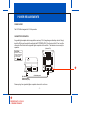
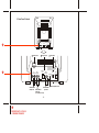
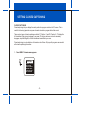
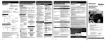
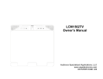
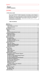
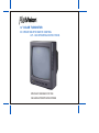
13 ” COLOR TV/MONITOR
DC OPERATION WITH REMOTE CONTROL
AVT–1498 OPERATING INSTRUCTIONS
SPECIALLY DESIGNED FOR THE
VAN AND AUTOMOTIVE INDUSTRIES
RECOMMENDED GUIDELINES FOR THE USE OF A
VIDEO MONITOR/TV IN A MOTOR VEHICLE
* A VIDEO MONITOR /TV is designed for rear passenger viewing only. This product may only be
installed in the rear seat compartment of the vehicle, out of the driver's view.
* Installation in any other area of the vehicle, including anywhere within the driver's view, is illegal in
most states, provinces and countries and may lead to driver distraction resulting in an accident, injury
and or death. If you are unsure of regulations regarding this, please consult your local laws to
determine how this applies to you.
* Users should be aware of the possible noise distraction caused by the use of the product and
should carefully monitor the volume so as not to interfere with the driver's attention to surrounding
traffic conditions.
EXPLANATION OF GRAPHIC SYMBOLS:
CAUTION
RISK OF ELECTRIC SHOCK
DO NOT OPEN
CAUTION: TO REDUCE THE RISK OF ELECTRIC SHOCK,
DO NOT REMOVE COVER (OR BACK)
NO USER-SERVICEABLE PARTS INSIDE
REFER SERVICING TO QUALIFIED SERVICE PERSONNEL
The lightning flash with arrowhead
within a triangle is intended to tell the
user that parts inside the product are a
risk of electric shock to persons.
The exclamation point within a triangle
is intended to tell the user that important operating and servicing instructions
are in the papers with the appliance.
WARNING: TO PREVENT FIRE OR ELECTRIC SHOCK HAZARD, DO NOT EXPOSE THIS PRODUCT
TO RAIN OR MOISTURE.
IMPORTANT SAFETY INFORMATION
1. Read Instructions — All the safety and operating instruction should be read before the appliance is
2.
3.
4.
5.
6.
7.
8.
operated.
Retain Instructions — The safety and operating instructions should be retained for future reference.
Heed Warnings — All warnings on the appliance and in the operating instructions should be adhered to.
Follow Instructions — All operating and use instructions should be followed.
Cleaning — Unplug this video product from the DC supplying outlet before cleaning. Do not use liquid cleaners or aerosol cleaners. Use a damp cloth for cleaning. Exception; A product that is meant
for uninterrupted service and that for some specific reason, such as the possibility of the loss of an
authorization code for a CATV converter, is not intended to be unplugged by the user for cleaning or
any other purpose, may exclude in the cleaning description other wise required.
Attachments — Do not use attachments not recommended by the video product manufacturer as
they may cause hazards.
Water and Moisture — Do not use this video product near water-for example, near a bath tub, wash
bowl, kitchen sink, or laundry tub, in a wet basement, or near a swimming pool, and the like.
Accessories — Do not place this video product on an unstable cart, stand, tripod, bracket, or table.
The video product may fall, causing serious injury to a child or adult, and serious damage to the appliance. Use only with a cart, stand, tripod, bracket, or table recommended by the manufacturer, or
sold with the video product. Any mounting of the appliance should follow the manufacturer’s instructions, and should use a mounting accessory recommended by the manufacturer.
9. Ventilation — Slots and openings in the cabinet are provided for ventilation, to ensure reliable operations of the video product and to protect it from overheating. These openings must not be blocked
or covered. The openings should never be blocked by placing the video products on a bed, sofa,
rug, or other similar surface. This video product should never be placed near or over a radiator or
heat register. This video product should not be placed in a built-in installation such as a book case
or rack unless proper ventilation is provided or the manufacturer’s instructions have been adhered
to.
10. Power Sources — This video product should be operated only from the type of power source indicated on the marking label. Video products intended to operate from battery power, or other
sources, refer to the operating instructions.
11. Lightning — For added protection for this video product receiver during a lightning storm, or when
it is left unattended and unused for long periods of timer, unplug it from the DC supplying outlet and
disconnect the antenna. This will prevent damage to the video product due to lightning.
12. Overload — Do not overload DC supplying outlets and extension cords as this can result in a risk of
fire or electric shock.
13. Object and Liquid Entry — Never push objects of any kind into this video product through openings
as they may touch dangerous voltage points or shortout parts that could result in a fire or electric
shock. Never spill liquid of any kind on the video-product.
14. Servicing — Do not attempt to service this video product yourself as opening or removing covers
may expose you to dangerous voltage or other hazards. Refer all servicing to qualified service personnel.
15. Damage Requiring Service — Unplug this video product from the DC supplying outlet and refer servicing to qualified service personnel under the following conditions:
a. When the power-supply cord or adapter is damaged.
b. If liquid has been spilled, or object have fallen into the video product.
c. If the video product has been exposed to rain or water.
d. If the video product does not operate normally by following the operating instructions. Adjust only
those controls that are covered by the operating instructions as an improper adjustment of other
controls may result in damage and will often require extensive work by a qualified technician to restore the video product to its normal operation.
e. If the video product has been dropped or the cabinet has been damaged.
f . When the video product exhibits a distinct change in performance-this indicates a need for service.
16. Replacement Parts — When replacement parts are required, be sure the service technician has
used replacement parts specified by the manufacturer that have the same characteristics as the
original part. Unauthorized substitutions may result in fire, electric shock or other hazards.
17. Safety Check — Upon completion of any service or repairs to this video product, ask the service
technician to perform safety checks to determine that the video product is in proper operating condition.
SERVICE SAFETY INFORMATION
1. For your protection, please read these instructions completely and comply with all warnings,
cautions and instructions placed on the set or described in the operating instructions.
2. Electrical components that are likely to be replaced in the field and that are critical with respect to
the safety are identified on the schematic diagram by the symbol ! .
3. Warning: This product includes critical mechanical and electrical parts which are essential for X
radiation safety. For continued safety replace critical components only with exact replacement parts
given in the parts list. Operating high voltage for this product is 20.16KV at minimum brightness.
POWER REQUIREMENTS
POWER SUPPLY
The AVT-1498 is designed for 12 Volt operation.
CAR BATTERY OPERATION
A cigarette lighter adapter cable is supplied for use in any 12 Volt, negative ground battery vehicle. Simply
insert the DC plug on the end of the cable into the DC POWER JACK (10) on the back of the TV set, and the
other end of the cable into the cigarette lighter receptacle of the vehicle. The television is now ready for
operation.
(Rear of TV)
CAUTION:
MEASURE DC SOURCE
POLARITY BEFORE USE
OTHERWISE, THE SET
MAY BE DAMAGED.
GND
ANT.
CAUTION:FOR CONTINUED PROTECTION
AGAINTS RISK OF FIRE REPLACE ONLY
WITH SAME TYPE 5A, 250V FUSE.
OUT
INPUT-1
VIDEO AUDIO VIDEO AUDIO
DC INPUT
12-14V
FUSE
T5A/250V
INPUT-3
VIDEO AUDIO
EXT. SPK.
DC
12-14V
+
–
•
DC JACK
DC JACK
Cigarette Lighter
socket of car (12V)
Car battery cord
Remove plug from cigarette lighter receptacle when unit is not in use
–1–
*
REVISED DATE : 07/04/03
– DRAWING CHANGE
*
1. Front Panel Controls
INPUT–2
ENTER MENU
AUDIO
CHANNEL
VOLUME
POWER
VIDEO
Å Remote Sensor
À POWER Button
Button
” and “ ” Buttons)
 CHANNEL
(Also “
INPUT–2
ENTER MENU
AUDIO
CHANNEL
VOLUME
POWER
VIDEO
Ä ENTER Button
Æ AUDIO/VIDEO Input Jack
(For “VIDEO 2 MODE”)
Á VOLUME Button
à MENU Button
–2–
(Also “ – ” and “+” Buttons)
À.
Á.
Â.
Ã.
Ä.
Å.
Æ.
POWER Button
• Press once to turn on TV.
• Press again to turn off TV.
VOLUME Buttons
• Press VOLUME “+” to increase volume, or press VOLUME “–” to decrease volume.
• The “+” and “–” buttons are also used to adjust the picture. When the PICTURE display disappears
from the screen. These buttons once again become the volume adjustment controls.
CHANNEL Buttons
• Press CHANNEL
to see the next higher channel in memory.
• Press CHANNEL
to see the next lower channel in memory.
• The
and buttons are also used to select desired function on the menu.
MENU Button
• Press the MENU button, the MENU display appears.
• Press or
to select desired function, then press ENTER button to end the choice.
• Details about using each function are on page 11.
ENTER Button
• To end the choice on the first menu or the second menu.
• Details about using each function are on page 11.
Remote Sensor
• Receives commands from remote control.
• When using the remote control, point it toward this sensor.
AUDIO/VIDEO Input Jack
• Use a audio/video cable to connect this jack to the audio/video output from a video camera, VCR,
video game, etc.
• These jacks on the front can only be used for direct audio and video input on the “VIDEO 2” mode.
–3–
2. Rear Panel Controls
ANT.
CAUTION:FOR CONTINUED PROTECTION
AGAINTS RISK OF FIRE REPLACE ONLY
WITH SAME TYPE 5A, 250V FUSE.
*
OUT
INPUT-1
VIDEO AUDIO VIDEO AUDIO
DC INPUT
12-14V
FUSE
T5A/250V
INPUT-3
VIDEO AUDIO
EXT. SPK.
DC
12-14V
+
–
•
12
Antenna Jack
11
DC Input Jack
8
Fuse Holder
ANT.
CAUTION:FOR CONTINUED PROTECTION
AGAINTS RISK OF FIRE REPLACE ONLY
WITH SAME TYPE 5A, 250V FUSE.
*
OUT
INPUT-1
VIDEO AUDIO VIDEO AUDIO
DC INPUT
12-14V
FUSE
T5A/250V
INPUT-3
VIDEO AUDIO
EXT. SPK.
DC
12-14V
+
–
•
14
13
AUDIO/VIDEO
11
AUDIO/VIDEO
Input Jack
Output Jack
AUDIO/VIDEO
Input Jack
(For "VIDEO 1" mode)
–4–
*
REVISED DATE : 07/04/03
– DRAWING CHANGE
9
External Speaker Jack
8 . FUSE Holder
9 .
10 .
11 .
12 .
13 .
*
14 .
• There is a safety fuse in the holder.
• The fuse is a 5-amp, 125/250V (slow blow type).
External Speaker Jack
• You can plug an optional Speaker into this jack for private listening.
• When the plug of an external speaker is attached, the sound will come through the external
speaker instead of the TV speaker.
DC Input Jack
• For car use, the TV is designed for negative (–) ground 12V DC operation only.
• When unit is not in use, remove the car battery cord from the cigarette lighter socket.
AUDIO/VIDEO Input Jack
• Use an audio/video cable to connect this jack to the audio/video output from a video camera,
VCR, video game, etc.
• These jacks on the rear can be used for direct audio and video input on the "VIDEO 1" mode.
ANTENNA Jack
• Connect the antenna cable to the VHF-UHF antenna terminal.
AUDIO/VIDEO Output Jack
• For connection to a monitor TV, audio/video system or VCR.
AUDIO/VIDEO Input Jack
• Use an audio/video cable to connect this jack to the audio/video output from a video camera,
VCR, video game and etc.
• These jacks on the rear can be used for direct audio and video input on the “VIDEO 3” mode.
–5–
*
REVISED DATE : 07/04/03
– ADD IN ITEM # 14 (AUDIO/VIDEO INPUT JACK)
DESCRIPTION OF PARENTAL CONTROL SETTINGS
1.
2.
3.
4.
The TV Guidelines set the standard for the TV programs, excluding sports and news. Use the
CH
buttons to select, – VOL + buttons to adjust. You can set individual settings with – VOL +
buttons.
The Movie ratings set the standard for movie, video, and other media excluding TV programs. Use
the
CH
buttons to select, – VOL + buttons to adjust.
The no rating item toggles between “Unblock” and “Block”. This item determines whether the
programs, which are not rated by “Movie Ratings” and “TV Guidelines”, will blocked or not. Use
VOL buttons to change the settings.
The password item will let you change password by entering the V-Chip Control item.
The initial password “1111” should be changed. Use – VOL + buttons to enter the password input
display, and use the number buttons (0-9) to enter a new 4-digit password. After you have entered
the new password, a confirmation display will appear. Punch in the password again.
–6–
BATTERY INSTALLATION
Before attempting to operate your Remote Control, install batteries as described below.
1. Turn the Remote Control face down. Press down on the ridged area of the battery cover and slide it
off.
2. Install two “AAA” batteries as shown. Make sure that proper polarity (+ or –) is observed.
3. Slide the cover back until it clicks.
–
+
+
–
–7–
REMOTE CONTROL OPERATION
1. TV PARTS:
1. TV POWER
Press this button to turn on the set.
Press the button again to turn the set off.
2. Direct Access (0-9, 1--) Number Buttons
Use these buttons to select a channel.
The channel number chosen will be displayed on the
screen for about four seconds.
To select channels 0-99, press two number buttons.
For example, to select channel 8, press 0, 8.
To select channels above 100, press the 1-- button,
then the number buttons for the last two digits of the
channel.
For example, to select channel 115, press 1--, 1, 5.
3. CHANNEL s/t Buttons
Use these buttons to advance to the next higher (s)
or lower (t) channel. (also used to select desired
function on the menu).
4. Volume +/– Buttons
Use these buttons to raise (+) or lower (–) the TV
sound level (also used to make picture adjustments in
picture selector mode).
–8–
6
TV POWER
MUTE
TV/VIDEO
7
1
2
1
2
3
ERASE/
ADD
4
5
6
TV/CATV
9
7
8
9
AUTO
PROGRAM
10
0
1-
ENTER
11
PICTURE
SELECTOR
8
12
CH s
3
VOL. –
VOL . +
MENU
4
CH t
13
14
16
5
VCP POWER
REW
F.FWD
REPLAY
PLAY
15
STOP
17
18
5. MENU Button
Press the MENU button. The MENU display appears.
Use s and t buttons to select desired function, then press ENTER button to end the choice.
6. TV/VIDEO Button
Press this button to access the AUDIO/VIDEO input jacks, on the front and rear of the TV. As the
button is pressed, the on-screen display will cycle as follows:
TV
VIDEO 1
VIDEO 2
VIDEO 3
7. MUTE Button
Press this button to turn the TV sound off. Press again to restore sound to the previously set level.
MUTE may also be released by pressing the VOLUME +/– buttons.
8. ERASE/ADD Button
This button is used to manually add or erase any channel that is stored in the CHANNEL s/t
memory. The stored channel numbers are displayed in GREEN on the screen and the non-stored
channel numbers are in RED.
9. TV/CATV Button
Use this button to select regular 69-channel broadcast TV or 125-channel cable TV (standard
cable, HRC cable, or IRC cable).
As the button is pressed, the on-screen display will cycle as follows:
AIR
CABLE-S
CABLE-H
–9–
*
REVISED DATE : 07/04/03
– DRAWING CHANGE
CABLE-I
*
10. AUTO PROGRAM Button
Select the regular channel broadcast TV or CABLE TV for AUTO PROGRAM. When the AUTO
PROGRAM button is pressed, the TV screen will show an IMPORTANT information screen, all
the channel numbers for TV or CABLE TV will be scanned. The broadcasting signals will be
detected and automatically stored.
IMPORTANT
Reception on any TV in a mobile
environment may be affected by:
Vehicle movement, weather,
distance from TV station, etc..
These factors may cause the
picture to roll, be snowy, and
cause some color loss.
For the best picture quality,
a VCP is recommended.
SCANNING AIR CH : 2–69 (for TV)
or
SCANNING CABLE CH : 1–125 (for CABLE TV)
11. ENTER Button
Use this button to end the choice on the menu.
Details about using each function are on page 11.
12. PICTURE SELECT Button
Each time this button is pressed the on-screen picture adjustment display cycles through
"adjustment screens" as follows:
CONTRAST
BRIGHTNESS
SHARPNESS
TINT
COLOR
Then use the VOLUME +/– buttons to raise (+) or lower (–) the level.
The display will automatically turn off if no adjustments are made within four seconds, or if any
other button is pressed.
–10–
2. VCP PARTS:
13. VCP POWER Button
This button is used to turn the unit on and off.
14. "REW" REWIND Button
If this button is pushed while the tape is stopped, the tape will rewind. If this button is pushed
while the tape is playing, the VCP will go into rewind search mode. For more information on
search feature of the VCP, consult VCP owner's manual.
15. PLAY Button
Press this button to activate play mode while a tape is loaded into the VCP. This button may also
be used to dis-engage search and pause modes. For more information, consult the VCP owner's
manual.
16. "F. FWD" FAST FORWARD Button
If this button is pushed while the tape is stopped, tape will fast forward. If this button is pushed
while the tape is playing, the VCP will go into fast forward search mode. For more information on
search feature of the VCP, consult the VCP owner's manual.
17. STOP Button
Press this button to stop the tape.
18. REPLAY Button
During playback, press this button to rewind the tape to the beginning and to begin PLAY mode
from there.
–11–
ADJUSTING THE PICTURE
When watching TV programs, the quality of the picture can be adjusted to suit your taste.
1.
Press MENU. The main menu appears.
MENU
2.
MAIN MENU
SELECT VIDEO
CLOSED CAPTION
SET PICTURE
AUTO-PROGRAM
ANTENNA INPUT
V-CHIP PROTECT
SET PASSWORD
Press either CHANNEL s or t to select the function.
Make sure the highlight bar is PICTURE and then press ENTER.
CHANNEL
MAIN MENU
SELECT VIDEO
CLOSED CAPTION
SET PICTURE
AUTO-PROGRAM
ANTENNA INPUT
V-CHIP PROTECT
SET PASSWORD
PICTURE
COLOR
CONTRAST
BRIGHTNESS
SHARPNESS
TINT
RESET
ENTER
–12–
3.
Select the item to adjust. For example:
To adjust brightness, press CHANNEL t or s to select BRIGHTNESS and press ENTER.
CHANNEL
PICTURE
COLOR
CONTRAST
BRIGHTNESS
SHARPNESS
TINT
RESET
4.
32 BRIGHTNESS
ENTER
–
+
Adjust the level:
Press VOLUME “–” or “+” to adjust the level.
VOLUME
–
+
50 BRIGHTNESS
–
+
–13–
5.
To adjust other items, repeat all above.
Notes:
• The menu or display disappears from the screen if you do not press – or + within a few seconds.
Whenever a menu or display disappears from the screen, the – and + buttons on the front of the TV
become the volume adjustment buttons.
• If you want to adjust the picture only. You can use the remote control, simply press the PICTURE
SELECT. Details are on page 9.
Description of adjustment items
Item
Adjustment
Press VOLUME – to
Press VOLUME + to
CONTRAST
Decrease picture contrast
for soft color
Increase picture contrast
for vivid color
BRIGHTNESS
Darken the picture
Brighten the picture
SHARPNESS
Decrease picture sharpness
Increase picture sharpness
TINT
Make skin tones become greenish
Make skin tones become purplish
COLOR
Decrease color intensity
Increase color intensity
To restore the factory settings
Select the item of PICTURE while the main menu is displayed.
Then select the item of RESET. All the picture functions (CONTRAST, BRIGHTNESS, SHARPNESS,
TINT, COLOR) will go back to the factory settings.
–14–
SETTING CLOSED CAPTIONING
CLOSED CAPTIONING
Closed captioning lets you display the audio portion of a program as text on the TV screen. This is
useful to the hearing impaired or anyone who wants to watch a program without the sound.
There are two types of closed captioning available: C1 (Caption 1) and C2 (Caption 2). C1 display the
full translation of the primary language in your area. C2 may be used as a source for secondary
languages, simplified English, or other translations transmitted in your area.
Closed captioning is not available on all channels or at all times. Only specific programs are encoded
with closed captioning information.
1.
Press MENU. This main menu appears.
MENU
MAIN MENU
SELECT VIDEO
CLOSED CAPTION
SET PICTURE
AUTO-PROGRAM
ANTENNA INPUT
V-CHIP PROTECT
SET PASSWORD
–15–
2.
Press either CHANNEL t or s to select the function.
Make sure the highlight bar is CAPTION and then press ENTER.
CHANNEL
MAIN MENU
SELECT VIDEO
CLOSED CAPTION
SET PICTURE
AUTO-PROGRAM
ANTENNA INPUT
V-CHIP PROTECT
SET PASSWORD
3.
CAPTION
CAPTION 1
ENTER
CAPTION 2
TEXT 1
TEXT 2
OFF
Press either CHANNEL t or s to select the item and then press ENTER.
CABLE TV (CATV) OPERATION
In addition to normal broadcast reception of VHF and UHF channels, if you are a cable TV subscriber,
your new TV is capable of receiving many unscrambled cable channels without the use of a converter
box.
When set to broadcast TV it receives channels 2 ~ 69. When set to one of the CATV modes (STD, HRC,
or IRC) it receives channels 1 ~ 125 (see chart on the following).
–16–
CABLE TV TUNING PROCEDURE
1.
2.
3.
Connect the CATV cable directly to the TV antenna terminal. Your local cable system operator's
converter box should not be required unless certain premium channels are scrambled.
Select the appropriate CATV setting with the TV/CATV button on the remote control.
You can now select CATV programs by using the CHANNEL s/t buttons or the number buttons on
the remote control. The chart below lists the total channel and cable count.
Channels
Off Air
Cable
Low VHF (Channel 01)
–
1
VHF (Channels 2 ~ 13)*
12*
12*
UHF (Channels 14 ~ 69)*
56
–
Low Midband A–5 ~ A–1 (Channels 95 ~ 99)
–
5
Midband (Channels 14 ~ 22 or A ~ I)
–
9
Superband (Channels 23 ~ 36 or J ~ W)
–
14
Ultraband (37 ~ 94 and 100 ~ 125 or w+29 ~ w+48)
–
84
68
125
Total*
–17–
PARENTAL CONTROL SETTINGS
This item helps parents set the standard for the programs their children are going to watch.
1.
2.
3.
4.
5.
6.
7.
8.
With the TV on, press the MENU button until “Special” menu will appear.
Use the t CH s buttons to select the “V-Chip Control” item.
Use the – VOL + buttons to enter into “V-Chip Control” settings.
After using the number buttons (0-9) to enter your password, the “V-Chip Control” menu will be
displayed. If this is the first time you are using your “V-Chip Control” menu, your default
password is “1111”.
Select the V-Chip Control feature. Use the – VOL + buttons to toggle “On” or “Off”.
Use the t CH s buttons to select the V-Chip Control settings you wish to adjust. Descriptions
of the V-Chip Control settings are on the next page.
Use the – VOL + buttons to adjust the V-Chip Control setting selected.
Use the MENU button to return to the menu on the next level up.
–18–
SETTING THE V-CHIP
An age limitation can be set to forbid children to see and hear violent scenes or pictures for adults, etc.
The TV/VCR responds to “TV RATING” and “MOVIE RATING”. To use the V-CHIP function, you must
register a password.
1. Press MENU. This main menu appears.
MENU
MAIN MENU
SELECT VIDEO
CLOSED CAPTION
SET PICTURE
AUTO-PROGRAM
ANTENNA INPUT
V-CHIP PROTECT
SET PASSWORD
1. Press either CHANNEL t or s to select the function.
Make sure the highlight bar is SET PASSWORD and then press ENTER.
MAIN MENU
SELECT VIDEO
CLOSED CAPTION
SET PICTURE
AUTO-PROGRAM
ANTENNA INPUT
V-CHIP PROTECT
SET PASSWORD
CHANNEL
s
s
ENTER
PASSWORD
SELECT VIDEO
CLOSED CAPTION
SET PICTURE
AUTO-PROGRAM
ANTENNA INPUT
V-CHIP PROTECT
OLD PASSWORD
–19–
3. Enter the OLD password (4 digits) using the Direct channel selection buttons (0-9).
4. Enter the NEW password (4 digits) using the Direct channel selection buttons (0-9).
NOTES : • The initial PASSWORD is “1111”.
• If you forget the password, you cannot set the V-CHIP.
• To avoid forgetting the password, write it down and Keep in a Safe place.
TO SET THE V-CHIP
1. Press MENU. The main menu appears.
MENU
MAIN MENU
SELECT VIDEO
CLOSED CAPTION
SET PICTURE
AUTO-PROGRAM
ANTENNA INPUT
V-CHIP PROTECT
SET PASSWORD
–20–
3. Press either CHANNEL t or s to select the function.
Make sure the highlight bar is V-CHIP PROTECT and then press ENTER.
MAIN MENU
SELECT VIDEO
CLOSED
SET PICTURE
AUTO-PROGRAM
ANTENNA INPUT
V-CHIP PROTECT
SET PASSWORD
CHANNEL
s
s
ENTER
PASSWORD
V-CHIP ON/OFF
TV
OFF
MOVIE
OFF
V/FV-VIOLENCE
SITUATIONS-S.
LANGUAGE-ADL.
DIALOG-S. SUG.
3. Enter the password (4 digits) using the Direct channel. Selection buttons (0-9).
“X” appears instead of the number.
Note : The initial password is “1111”.
4. In the V-CHIP PROTECT menu. Press either CHANNEL t or s to select the function.
5. Press either VOLUME + or VOLUME – to select the desired setting.
6. TV RATINGS CHART:
OFF : TV RATING is not set
TV-Y : ALL children
TV-Y7 : 7 years old and above
TV-G : General Audience
–21–
TV-PG : Parental guidance
TV-14 : 14 years old and above
TV-MA : 17 years old and above
• When you select TV-Y7, TV-PG, TV-14 or TV-MA, press either CHANNEL t or s to select the contained
rating.
V/FV-VIOLENCE
SITUATIONS-S.
LANGUAGE-ADL.
DIALOG-S SUG.
• Press VOLUME + or – to block (RED) and unblock (GREEN).
NOTE : The V-CHIP function is activated only on programs and tapes that the rating signal.
7. MOVIE RATINGS CHART :
OFF
G
PG
PG-13
R
NC-17
X
N/R
: MOVIE RATING is not set
: ALL ages
: Parental guidance
: Parental guidance, less than 13 years old
: Under 17 years old, Parental guidance suggested
: 17 years old and above
: Adult only
: Movie has not been rated or ratings do not apply
• Press VOLUME + or – to select the contained rating.
–22–
TECHNICAL INFORMATION
The following information will address TV antennas and attempt to give some insight into how TV
antennas and their application affect television performance.
UHF/VHF FREQUENCIES
VHF (CH 2 - 13) and UHF (CH 14 - 69) signals are nearly identical with one critical difference:
“wavelength.” VHF wavelengths are longer than UHF wavelengths. Therefore, the best antenna is
one that closely matches the wavelength of the signal you are trying to receive.
Also keep in mind that VHF wavelengths are significantly reduced when obscured.
ANTENNAS
Following are a few points to consider in regards to installing and choosing an antenna:
Metallic Paint
Manufacturers of boomerang antennas warn users that painting antennas with metallic paint will
hurt performance. This is also true for foil antennas used in fiberglass high tops that are painted.
Outside Metal
When TV antennas are used inside low top van conversions, the TV signal can be obstructed by the
outside metal of the vehicle. This will diminish UHF performance and may eliminate VHF reception
altogether. However, depending on antenna’s location and the direction of the vehicle, some VHF
signal may be received.
–23–
Loss of Signal
Loss of signal is another factor which should be considered. Every connection between the antenna
and the TV will reduce signal. Coax connectors improperly attached to antenna cables will cause
even more loss. Partially grounded roof rack antennas will also effect reception, especially VHF.
Testing done on antenna systems has shown that as much as a 10% loss of signal can be measured
across every connection. Multiplying this figure by the number of connections, (antenna to VCP, to
Nintendo, to TV) equates to a significant reduction in signal. Splitters, A/B switches and even the
type of coax cable used will effect antenna performance.
Our televisions are also designed to be monitors as well. Some of our customers are taking
advantage of this feature by running RCA patch cords from the VCP to the TV audio/video inputs.
This reduces the amount of connections required and will improve reception.
The information in this bulletin is not intended to promote or discourage the use of any one antenna,
but to caution. Approval of antenna performance and application, should not be given without
adequate testing in both VHF and UHF areas.
–24–
TECHNICAL INFORMATION
The following information will discuss DC power sources and how they affect 12 volt DC Audio and
Video products.
DC (DIRECT CURRENT) POWER
A large number of our products are designed for 12 volt DC applications. The power is supplied by
a variety of sources i.e., the battery, converters, ignition systems and solar power.
General Specifications
Our general specification for the voltage range of operation is 10 to 16 volts DC. TV's and VCP's
(video cassette players) require slightly more than 10 volts to function properly. Normally this 10.5 to
11 voltage requirement does not create a problem, but keep in mind the following points:
Voltage
The voltage of a fully charged battery (engine not running) is approximately 12.5 VDC. Once a load
(items being powered represent the “load”) is applied, the voltage will drop. How much the voltage
is reduced will depend on the following:
1. Current draw (amount of amperage). The higher the draw the greater the voltage will drop.
2. The size and length of the conductor (wire) supplying power.
–25–
Amperage
A TV will draw considerably more amperage than a VCP. For instance, a 9” TV will draw
approximately 3.0 amps compared to a VCP that draws 1 amp while the tapes are being loaded or
ejected.
Checking the voltage of a TV while it is playing shows an approximate 1 volt drop, (11.5 VDC). The
voltage at the VCP can be another .5 VDC (11 VDC) less than the TV.
In conclusion, operating these video products without the engine running will drain the battery to
the point where these products will perform unacceptably in a short period of time.
Converters
Many RV OEM's incorporate converters as a source of 12 VDC when connected to shore power
(110-120 VAC). Some models put out a very clean DC supply where others may have a
considerable amount of AC ripple under maximum load.
This AC ripple is filtered by the coach battery when connected into the circuit, but when the battery is
removed or disconnected the amount of AC ripple can create major problems for audio and video
products. Noise may result and often times in line fuses fail.
Ignition Systems
Unwanted noise generated from ignition systems used to be a big problem. However, with more
sophisticated filtering circuits designated into audio/video products, these problems are not as
wide spread.
Changes in wire harnessing also has contributed to the decline of application problems. One rule of
thumb is to use the same ground point for all related products. This will greatly reduce the potential
for alternator whine.
–26–
TROUBLESHOOTING
SYMPTOM
No Power
CAUSE
No 12 volt DC power to the
set
POSSIBLE SOLUTION
*Check circuit fuse at source of
power (see vehicle owners
manual)
Be sure TV switch in
overhead switch panel is on
Indicator light on front of
set is not on
Power cord is not plugged
into DC outlet
*Check that power cord is plugged
into jack of TV
DC power plug is not
inserted into the jack on
the TV
*Check in-line fuse of power cord
to set either on red wire or in
lighter plug
*Check fuse in TV (20 x 5 mm
5 amp)
*Check (unplug power cord) and
test for 12 VDC positive and
ground at coaxial DC plug
*Turn on overhead switch panel
(if applicable) may control power
to TV
–27–
SYMPTOM
Set will not turn on by
remote, indicator dimly lit
CAUSE
POSSIBLE SOLUTION
TV’s remote sensor blocked *Depress power button on front of
TV
Remote control inoperative
*Start vehicle engine
Discolored areas of
picture (purple)
Remote not in direct line
with TV’s infrared sensor
*Check for weak connection
Batteries in remote
*Replace Batteries
Low voltage, low battery
power
*Replace Batteries
Magnetic fields
Turn TV on for one minute, turn TV
off for 10 seconds then turn back
on. TV will “ degauss ” and correct
discoloration
NOTE : If degauss feature
will not correct or reoccurs,
demagnetizing metal near
TV may be necessary (call
van converters service
department)
–28–
SYMPTOM
Picture/No Sound
CAUSE
*External Speaker switch in *Switch exterior speaker to on
off position
position
*TV muted
*Switch mute off with remote
*External speaker circuit
broken
*Unplug external speaker plugsound should come through front
speaker
*Volume level at minimum
*Raise volume with remote or
volume button on front of set
behind control door
No Picture, sound or local *TV in video mode
reception
*TV in one of three STDHRC-IRC cable modes
Poor or weak reception
POSSIBLE SOLUTION
*Switch to TV mode with TV/Video
on remote or TV/AV button on front
of set behind door
*No connection to antenna
Switch to TV with TV/CATV button
on remote. On-screen will display
mode
*Vehicle is in motion
*Adequate reception often cannot
be maintained in a moving vehicle
–29–
SYMPTOM
Poor or weak reception
Poor or weak reception
CAUSE
POSSIBLE SOLUTION
*VCP power on
(if applicable)
*Turn off VCP
*Connections between
antenna and TV
*Bad or poor coax connections;
consult converter or manufacturer
for antenna routing
*Antenna not connected to
TV
*Check connection on rear of set.
Antenna may be routed through
VCP (check antenna connection
to VCP)
*Antenna grounded to
vehicle. Elements of
antenna must be isolated
chassis ground
*Check antenna (mainly rack type)
or grounding to vehicles chassis,
will require OHM meter
*Bad antenna
*Connect good antenna
–30–
ACCESSORIES LIST
DESCRIPTION
AVT-1498 13" Color Television with remote (12 Volt)
AVT-988 9" Color Television with remote (12 Volt)
AVT-597 5" Color Television with remote (12 Volt)
AVT-975 9" Color Television with remote (12 Volt)
AVT-1475 13" Color Television with remote (12 Volt)
AVP-6750 Video Cassette Player (12 Volt)
BPA-501-12 - 4 amp Adapter for use with AVT-975/AVT-988 9"
and AVT-1498/AVT-1475 13" Televisions
AC2A - 2 amp Adapter for use with AVT-597 5"
TV and AVP-6750 Video Cassette Player
Unified Remote Control
VAC-21 – 12 Volt Corded Vacuum
VAC-32 – 12 Volt Rechargeable Vacuum
AVF-1 Rechargeable Flashlight
HP-175 Headphones with Pivoting Ear Cup
HP-275 Headphones with Volume Control on Cord
HP-375 Studio Quality Headphones
PART NUMBER
08001480
08000988
08000597
08000975
08001475
09006750
0891412
0891436
0893225
4185998
4110032
4130001
4120175
4120275
4120375
Unlike household electronics, all of our products have been specifically designed and tested
for the mobile environment and are only available through ASA. To order any of these
products please call Audiovox Specialized Applications at 219-264-3135 or 800-688-3135
–31–
AUDIOVOX SPECIALIZED APPLICATIONS, LLC
23319 COOPER DRIVE, ELKHART, IN46514
2003 A .S.M.C.
PRINTED IN MALAYSIA