1
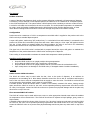
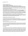
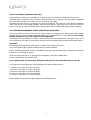
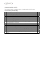
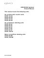
CRYOCOOL Systems
Product Manual
This manual covers the following units
Air cooled under counter units
CRYO 10 AU
CRYO 20 AU
CRYO 30 AU
CRYO 40 AU
Air cooled floor standing units
CRYO 40 AF
CRYO 50 AF
CRYO 60 AF
CRYO 70 AF
CRYO 90 AF
CRYO 100 AF
Water cooled floor standing units
CRYO 80 WF
CRYO 100 WF
Issue 2 06/05/05
Contents
Page
The System
Product Overview
Configuration
3
3
Handling and transportation
3
Location
3-4
Installation
CRYO AU & AF Coolers
CRYO WF and Discharge Coolers
Product Lines
Bypass Valve
Trace Cooling
Glycol lines/Wiring
Cellar Checklist
Bar Checklist
4
5
5
5
5
6
7
8
Commissioning
Trace Cooling
9
Product Supply
Cleaning Lines
Cleaning Socket Labels
9
9
Maintenance
10
System Schematics
11-12
Spares Lists and Exploded Views
13-16
Fault Finding
17-18
Glycol
Freezing points
Brix mix
Refractometer Usage
19
20
21
2
The System
Product overview
A range of draught beer dispense glycol cooling systems delivering consistently cold temperatures (between
2oC and 4oC) from a minimum of one dispense point in the CRYO 10 AU to a maximum of 14 dispense points
in the CRYO 90 AF/100 WF. The system utilises a CRYO system cooler containing a sub zero coolant. Product
is cooled in coils which are immersed in the sub zero coolant. The cooled product temperature is maintained
by using a super chill python installed between the CRYO system cooler and the dispense point. A ‘clean
mode’ allows cleaning solution and water to be drawn through the product coils without freezing.
Configuration
Product stored at a maximum of 13oC in a temperature controlled cellar is supplied to the product coils in the
CRYO cooler by a standard dispense panel.
A super chill python, made using 3/8” product lines, 2 x recirculation lines and insulated, is connected to the
product coil outlets and recirculation pump flow and return. When using a 14 line super chill python connect
only the 12 lines which are wrapped within the 19mm insulation, the other 2 are built in for redundancy
purposes and should not be used, drinks will be out of specification if they are.
The glycol mix in the CRYO cooler’s coolant bath is pumped around the super chill python to maintain the
temperature of the product between the CRYO cooler and the point of dispense.
Trace cooling is recommended to maintain the casual drink temperature within specification.
Handling and Transportation
•
•
•
•
Keep the CRYO coolers in an upright position during transportation.
Do not drag the CRYO coolers over rough floors or down steps.
Keep the CRYO coolers in an upright position and do not move when the coolant bath is full.
Upon receipt ensure no damage to the CRYO cooler, if damaged contact Cornelius immediately.
Location
Under counter CRYO AU coolers
The CRYO AU coolers may be sited under the bar, close to the point of dispense, in an ambient air
temperature not exceeding 40°C. Allow 80mm clearance around the unit to aid air circulation and keep the
front of the unit clear to allow an unimpeded fresh air supply to enter the cooler. The CRYO AU coolers should
not be exposed to liquid spillage, spray, steam or high humidity.
A suitable position should be chosen within 2 metres of an earthed, switched 13A socket, leaving enough
space around the CRYO AU cooler for the unit’s correct operation/servicing requirements. Site CRYO coolers
on a firm, level support. Locate the CRYO AU coolers as to protect from physical damage and do not place any
other items on top of the unit.
Floor mounted CRYO AF coolers
The CRYO AF coolers may be sited within store rooms or other appropriate internal areas where the ambient
air temperature will not exceed 40°C. The CRYO AF should not be exposed to liquid spillage, spray, steam or
high humidity.
A suitable position should be chosen within 2 metres of a 13A socket, leaving enough space around the CRYO
AF cooler for the unit’s correct operation/servicing requirements. Site CRYO coolers on a firm, level support.
Locate the CRYO AF cooler as to protect from physical damage and do not place any other items on top of the
unit.
3
Location continued
Floor mounted CRYO WF coolers
The CRYO WF coolers may be sited within cooled cellars, store rooms or other appropriate internal areas
where the ambient air temperature will not exceed 40°C, however when used in the CRYOCOOL system it is
better to site the CRYO WF coolers in the temperature controlled product store. The CRYO WF coolers should
not be exposed to liquid spillage, spray, steam or high humidity.
A suitable position should be chosen within 2 metres of a 13A socket, leaving enough space around the CRYO
WF coolers for the unit’s correct operation/servicing requirements. Site CRYO coolers on a firm level support.
Locate the CRYO WF coolers as to protect from physical damage and do not place any other items on top of
the unit.
The CRYO WF coolers use conventional remote discharge coolers to remove waste heat from the refrigeration
unit. The discharge coolers can be sited up to 50 metres from the CRYO WF coolers (follow instruction
guidance from the discharge cooler) The electrical connections between CRYO WF coolers and discharge
coolers must be made with suitable 1.5mm2 cable, and the coolant lines using 15mm O.D tubing, with a
sufficient bore to ensure a minimum flow in this circuit of 4.5litres/minute.
Installation
CRYO AU coolers
Warning, this appliance must be earthed!
Caution, avoid spilling the glycol mix, wipe excess glycol away as it is slippery!
Installation must only be carried out by a suitably trained person and comply with national and local codes for
connection to the electrical supply. It is recommended that the mains electrical supply is protected by an
RCCB.
Locate the CRYO AU cooler in a selected position within 3 metres, including 1 metre lift, of the dispense point
(for a CRYO AU cooler fitted with a Number 2 pump) and 8 metres, including 1 metre lift, (for a CRYO AU
cooler fitted with a Number 6 pump). The 13A 230V socket should be within 2 metres of the CRYO AU cooler
and should be easily accessible for isolation. The socket should be installed in accordance with current I.E.E
regulations.
Fill the coolant bath with glycol and water (mixed at 30% glycol, 70% water). The coolant bath should be
filled with this glycol mix until the mixture flows out of the overflow. Fit the overflow cap when the mixture
has stopped dripping from the overflow.
CRYO AF coolers
Warning, this appliance must be earthed!
Caution, avoid spilling the glycol mix, wipe excess glycol away as it is slippery!
Installation must only be carried out by a suitably trained person and comply with national and local codes for
connection to the electrical supply. It is recommended that the mains electrical supply is 13A 230V protected
by an RCCB. The socket should be no further away than 2 metres of the CRYO AF cooler, be easily accessible
for isolation and be installed in accordance with current I.E.E regulations.
Locate the CRYO AF cooler in a selected position on a firm level support, within 30 metres of the dispense
point (for CRYO AF 40, 50 & 60 coolers fitted with a 3 stage pump) or 40 metres (for CRYO AF 70 & 90
coolers fitted with a 4 stage pump). Avoid warm areas (i.e. cupboards or small storerooms).
Fill the coolant bath with glycol and water (mixed at 30% glycol, 70% water). The coolant bath should be
filled with this glycol mix until the mixture flows out of the overflow.
4
CRYO WF and Discharge Cooler
Warning, this appliance must be earthed!
Caution, avoid spilling the glycol mix, wipe excess glycol away as it is slippery!
Installation must only be carried out by a suitably trained person and comply with national and local codes for
connection to electrical supply. It is recommended that the mains electrical supply is protected by an RCCB.
Locate CRYO WF coolers in selected position on a firm level support, within 2 metres of a 13A, 230 volt socket
which should be easily accessible for isolation of the CRYO WF coolers. The socket should be installed in
accordance with current I.E.E regulations.
Locate the CRYO WF cooler in a selected position on a firm level support, within 40 metres of the dispense
point (for CRYO WF 80 & 100 coolers fitted with a 4 stage pump)
Fill the coolant bath with glycol and water (mixed at 30% glycol, 70% water). The coolant bath should be
filled with this glycol mix until the mixture flows out of the overflow. See below Glycol Lines/Wiring
The discharge cooler should be mounted on an exterior wall, not south facing, and provide access for pipes
and electrical cable to the base unit (maximum 50m). If no exterior wall is available then mount inside on a
wall in a cool room with plenty of fresh air ventilation. Avoid warm areas (i.e. cupboards or small storerooms).
Secure the discharge cooler to the chosen location and fix (follow instruction guidance from the discharge
cooler) The CRYO WF coolers can be run with the units switched to ‘clean’ mode (cools to approximately 2°C)
and the top mounted pump disconnected, to ensure the integrity of the discharge cooler circuit.
N.B. The fan in the discharge cooler is controlled by a thermal switch mounted in the base of the
CRYO 80 & 100 WF. It may switch the fan off when air into the discharge unit drops below
approximately 12oC or when the glycol temperature falls below 38oC.
CRYO AU, AF & WF coolers product line connections
All tubing/pythons must be routed to prevent undue stress, tight bends or kinking.
From the sub zero python connect the recirculation lines to the flow and return of the top mounted
recirculation pump on the CRYO coolers. From the dispense panel in the temperature controlled cellar connect
the product lines to the inlet of the product coils of the CRYO coolers. Connect product lines of the super chill
python to the outlet of the product coils of the CRYO coolers. Note: All lines to be well insulated to the
requirements of the system.
Bypass Valve (Required for CRYO AF & WF coolers only)
At a convenient point immediately after the furthest dispense tower from the cooler, the pre-insulated bypass
valve needs to be fitted to ensure suitable differential pressure is maintained between the flow and return
lines. Connect the valve between the flow and return lines, ensuring the arrow on the valve is pointing in the
direction of the return manifold. Connections between python insulation and the valve can be sealed using
PVC tape and/or Armaflex tape.
See installation checklist below
Trace Cooling
To allow trace cooling, a ‘T’ piece is fitted in the recirculation flow line allowing the glycol to circulate around
the trace cooling loop and return into another ‘T’ piece fitted in the recirculation return line. To encourage
flow through the trace cooling loop a pressure bypass valve is fitted between the flow and return at the end of
the super chill python (AF & WF coolers only); this creates a pressure difference of approximately 10psi
between the recirculation flow and return. The trace cooling flow rate is adjusted using a flow regulator
located in the return trace cooling line before it re-enters the ‘T’ piece in the return python line. A nominal
flow rate of 1 litre/minute (adjusted when commissioning) ensures adequate cooling under most conditions.
Note: Where capillary tube is less than 0.75m long and where the 9.5mm beer line is terminated close to the
python exit point, trace cooling may be omitted. For all other instances trace cooling will be required.
5
Glycol Lines/Wiring (CRYO WF units only)
Using a minimum 1.5mm2 two core cable for a maximum 50m run, connect the Discharge Cooler to the
CRYO WF cooler. Connect the two core cable to the bottom two pins on the plug. The plug socket is located at
the rear of the CRYO WF cooler (Note: This is a nominal 24 volt supply).
Complete the glycol circuit by connecting the pipe work between the CRYO WF cooler and the discharge
cooler with the aid of the fittings provided. Avoid ups and downs in each glycol line as this may create air
locks. Do not kink or crush the tubing, ensure minimum bend radii of 100mm and support where necessary.
THE LINES SHOULD NEVER BE TAPED TOGETHER OR INSULATED!
As the glycol lines will carry a hot glycol mix under pressure it is important for safety reasons that suitable
tubing is used. Consult a specialist tubing manufacturer or contact Cornelius in case of difficulty. PVC tubing,
whether braided or not, is not suitable for this application.
The tubing ID must be sufficient to ensure a minimum flow rate of 4.5 litres/minute in the glycol circuit. For a
run of 50m an ID of at least 11.5mm will be required. Avoid using elbow joints as these cause pressure drops.
Glycol Mix
Mix monopropylene glycol and water to give a solution of 30% glycol 70% water.
Do not use ethylene glycol. Glycol should be mixed in a clean container.
Ensure sufficient glycol/water mixture is available for pouring into both tanks before switching the CRYO WF
coolers on. You will need to prepare:
24 litres of glycol then top up, to just above the evaporator, with water (Coolant bath)
9 litres of glycol/water mix (coolant tank)
As the glycol/water mix drops keep filling the bath/tank. Do not allow the pumps to run dry!
The system will require topping up with glycol/water mix at the following ratio’s:
2.1 litres for every 10m of 11.5mm ID tubing
4.2 litres for every 20m of 11.5mm ID tubing
6.3 litres for every 30m of 11.5mm ID tubing
8.4 litres for every 40m of 11.5mm ID tubing
10.5 litres for every 50m of 11.5mm ID tubing
Refer to pages 18, 19 and 20 for glycol graphs and refractometer use.
6
CRYOCOOL Installation Check list
These sheets are intended as a guide to a method of installation of the CRYOCOOL System.
Cellar Installation (CRYO AF & WF)
1
Site Cooler(s) (CRYO AF & WF)
2
Install heat dumps in position (CRYO WF coolers only)
3
Run pipe work and cable to heat dumps (CRYO WF coolers only)
4
Fill CRYO Cooler with glycol to correct strength (CRYO WF coolers only)
5
Fill coil in bottle with glycol (CRYO WF coolers only)
6
Connect cooler to power supply with Glycol Recirculation pump unplugged and unit in
CLEAN MODE (CRYO WF coolers only)
7
With the CRYO cooler in clean mode switch on and check for leaks
8
Install product lines from dispense panel to cooler
9
Install python between cooler position and bar, leaving enough length to Top and Tail
10
Connect recirculation tubes to cooler
11
Connect product lines to cooler ensuring all exposed tubing is insulated 3/8 fittings (not
supplied)
7
Bar Installation
1
Site coolers (CRYO AU only)
2
Run python into position in bar
3
Pull out product lines from python close to and beneath relevant font re-taping as
you go
4
Fit flow control to product lines (not supplied) keeping 3/8 pipe to minimum
between flow control and python
5
Connect restrictor tube between flow controls and taps. Tape and insulate
6
Fit trace cooling tees into python as required and insulate
7
Fit Pressure Balancing valve between flow and return. (Arrow in direction of Flow)
Tape and insulate (CRYO AF & WF coolers only)
8
Switch unit on in clean mode and check for leaks (CRYO AU coolers only)
9
Plug in Glycol Recirculation pump and check for leaks (CRYO AF & WF)
10
Top cooler tank up with Glycol
11
Draw water through product lines to check for leaks
12
Ensure all connections are taped and insulated
13
Check flow rate with water as per product specification
14
Sanitise Lines
15
Draw beer through each line to font. Adjust flow rate if required
16
Ensure all water has been purged from system before switching the Cooler to ‘run’
mode
17
Commission system
8
Commissioning
The CRYO coolers will cool glycol to a sub zero temperature- DO NOT TOUCH.
Before switching the CRYO AU, AF & WF to ‘cool’ mode ensure that all coils are purged with product!
Commissioning can only be successfully completed when:
• Recirculation pump is running and all components are installed and connected
• Glycol bath temperature remains between set range of temperatures.
Ensure products dispensed at between 2°C and 4°C.
Note: The temperature controller on the CRYO coolers do not require any alteration during set up, they are
factory set to the parameters required.
Trace cooling (if applicable)
Begin with setting the trace cooling flow on each trace cooling loop. Turn the knurled knob on the flow
adjustment valve 1.5 turns anticlockwise, from fully closed. This will give approximately 1 litre/minute, which
is sufficient for maintaining cooled product in the lines.
Product Supply
Cleaning lines
All product lines should be sterilised using known procedures and cleaning chemicals. It is absolutely essential
that all traces of water are removed from extra-cold product lines before commissioning begins. Failure to do
this will result in frozen coils, and damage to the system may result. Suggest, ensuring the CRYO coolers are
at the correct temperature to perform the cleaning operation switch to “clean” at the end of the evening and
perform the cleaning operation the next day.
Cleaning socket labels
Cleaning reminder labels (supplied) should be installed adjacent to the extra-cold cleaning sockets in the
cellar. In accounts where it is felt that the cleaning regime may be overlooked, additional labels (not supplied)
can be fitted to the keg connectors.
9
Maintenance (Faults/Repairs)
•
•
•
There are no user serviceable items inside the equipment.
Maintenance must only be carried out by a properly qualified and trained person.
Switch off the mains supply and unplug the equipment if it malfunctions or receives any physical
damage causing it to become unsafe and/or working outside the parameters set in this document.
User Maintenance
•
•
•
•
•
Switch off and unplug the unit during maintenance operations. Do not remove any protective covers.
Ensure grills and condenser fins remain unobstructed and free from dust/fluff etc. at all times to
ensure reliable and consistent performance. A soft brush or vacuum cleaner may be used for cleaning.
Ensure that objects are not placed on top the unit as this may affect its function.
Product coils/lines should be cleaned by flushing with water followed by a chlorinated alkaline
sanitising agent and final potable water flush when tainting is evident or when advised by the
equipment installer or beverage supplier. It is important that the sanitising agent manufacturer’s
procedure and safety precautions are followed when using caustic chemicals.
The 1989 Electricity at Work Regulations require periodic testing of electrical equipment and this
should only be carried out by a competent person.
Compliance To Standards And Legislation
All coolers comply with Brewers Society Code of Practice for Electrical Safety in Beer Dispense in License
Premises. Designed to EN60335-1,2-24 (Safety of Household and Similar Electrical Appliances-General
Requirements) Product coils are made from 316 stainless steel. Product complies with the EMC Directive
89/336//EEC as amended by 92/31/EEC and Low Voltage Directive 73/23/EEC as amended by 93/68/EEC.
10
System Schematic
Bar and Cellar area CRYO AU/AF/WF
ΙΜΙ ΧΟΡΝΕΛΙΥΣ (ΥΚ)
ΛΤ∆
11
System Schematic
Bar area CRYO AU/AF/WF
12
SPARES LIST
CRYO 80 & 100 WF
ITEM
PART No.
1
58 0420 591
TOP PUMP 4 STAGE
2
06 0 105103
GLYCOL BOTTLE
06 0 105104
LID GLYCOL BOTTLE
2MC824A
15ISV
DESCRIPTION
GLYCOL PROPYLENE 4 LTR
BALL VALVE 15mm
3
58 0440 429
TRANSFORMER BASLER BE30691-002
4
58 0400 098
TEMPERATURE CONTROL PRE 14/04/05
4
58 0400 135
TEMPERATURE CONTROL POST 14/04/05
58 0400 091
FAN SWITCH T/STAT K55 RANCO(bronze phial)
58 0400 092
THERM CUTOUT STAT K36-PI366000(silver phial)
44 0000 256
COMP SET 34cc – CAJ4511Y CRYO 100
3TS008A
COMPRESSOR START RELAY CRYO 100
3TS017A
COMPRESSOR START CAPACITOR CRYO 100
3TS026A
OVERLOAD CRYO 100
3TS029A
RUN CAPACITOR CRYO 100
5
58 0900 086
3DF001A
COMP SET 21cc CRYO 80
COMPRESSOR START RELAY CRYO 80
58 0420 143
COMPRESSOR START CAPACITOR CRYO 80
6
06 0 105127
BEZEL LENS (x2)
7
58 0410 216
FAN MTR (COMPRESSOR COOLING) CRYO 100
8
58 0420 610
n/s
99 2MR400A
FAN MOTOR - 24v 50Hz (HEAT DUMP)
n/s
58 0450 097
THERMOSTATIC EXPANSION VALVE
n/s
58 0450 098
ORIFICE
n/s
3SW004A
n/s
58 0400 075
PUMP GLYCOL
CLEANING SWITCH
CLEANING SWITCH THERMOSTAT
IMI Cornelius (UK) Limited
Rawson Spring Way, Riverdale Industrial Estate, Sheffield S6 1PG
Tel: 44 (0) 1142 855886
Fax 44 (0) 1142 321070
13
EXPLODED VIEW
CRYO 80 & 100 WF
SYSTEM SPARES
CRYOCOOL
PART No.
CZZ 096 122 402
PART No.
DESCRIPTION
96VA TRANSFORMER
DESCRIPTION
07 0 001589
INSULATED STRAINER
PART No.
07 0 001587
DESCRIPTION
DIFFERENTIAL PRESSURE VALVE
PART No.
38 0 27431
DESCRIPTION
FLOW CONTROL VALVE
14
SPARES LIST
CRYO 50 & 60 AF
ITEM
1
PART No.
DESCRIPTION
58 0420 592 No 15 PUMP ASSY CRYO 50
58 0420 591 4-STAGE PUMP ASSEMBLY CRYO 60
2
58 0400 075 THERMOSTAT WATERBATH
3
06 0 130247 CASSETTE COIL CRYO 50
06 0 130338 CASSETTE COIL CRYO 60
4
06 0 105113 HANDLE
5
44 0000 207 COMP SET FR11GX HST CRYO 50
99 0420 090 COMPRESSOR START RELAY CRYO 50
99 0420 059 COMPRESSOR CAPACITOR CRYO 50
44 0000 209 COMPRESSOR SET SC18G CRYO 60
6
99 2914 201 FAN MOTOR CRYO 50
58 0410 203 FAN MOTOR CRYO 60
7
58 0431 015 FAN BLADE CRYO 50
85 6012 045 FAN BLADE CRYO 60
8
06 0 131111 FAN BRACKET CRYO 50
06 0 131307 FAN BRACKET CRYO 60
9
06 0 135103 SERVICE PANEL
10
06 0 138205 LOGO CRYO 50
06 0 138302 LOGO CRYO 60
11
58 0404 001 CONTROLLER CRYO 50
06 0 130281 CONTROLLER CRYO 60
12
58 0475 214 HANDLE – LID
13
06 0 135203 HATCH – INSPECTION CRYO 50
06 0 105131 HATCH – INSPECTION CRYO 60
IMI Cornelius (UK) Limited
Rawson Spring Way, Riverdale Industrial Estate, Sheffield S6 1PG
Tel: +44 (0) 1142 855886
Fax +44 (0) 1142 321070
www.corneliusuk.com
15
EXPLODED VIEW
CRYO 50 AF
16
CRYOCOOL SYSTEM
Is Cooler
plugged in and
No
Cooling
Yes
Is cooling problem
restricted to one
cooler?
Is Cooler plugged
in and turned on?
No
Plug in cooler and
turn on
Yes
Is the Glycol/water mix
between -2o and -4oC?
No
Yes
See CRYO 100 WF
fault finding below
Is top pump
working correctly?
No
Yes
Check cellar temp.
and the length of
time the product has
been stored in the
cellar
No
CRYO 100 WF is
working correctly
Yes
Product temp. correct
Correct the cellar temp. and
ensure product is stored in the
cellar for at least 48hrs before
dispensing
17
Fault Finding cont..
CRYOCOOL SYSTEM
Is Cooler
plugged in and
Is cooling problem
affecting all products on all
towers?
Has CRYO 100 WF
been turned off at the
socket?
Yes
Switch on the supply at
the socket
Yes
Has the CRYO 100 WF
RCD tripped?
No
Yes
Is recirc top pump
running?
Reset RCD
No
Is pump plug
connected to the
socket?
Yes
No
Refit
Does the pump
run?
Yes
Is the glycol mix in the bath
on the CRYO 100 WF full
and between -2 & -4oC?
Call service
engineer
18
No
Yes
Glycol
Glycol Freezing Points
A 30/70 mix of Glycol/Water has a freezing point at around -14ºC (Refer to Graph 1)
Graph 1.
19
Glycol Mix Brix
A 30/70 mix of Glycol/Water has a sugar percentage (Brix) of around 20% (Refer to Graph 2)
Graph 2.
20
Refractometer Usage
Instructions for the use of the hand refractometer for measuring Glycol/Water Concentrations
Calibration
•
Flip open the daylight plate, which covers the prism.
•
Apply one or two drops of clean tap water onto the prism, using a soft applicator, such as a cable
tie.
•
Close the daylight plate.
•
Holding the refractometer up to the light, look at the scale through the eyepiece, turning the
eyepiece assembly until the boundary line, created by the water, is in sharp focus.
•
Using the small adjuster screw just in front of the daylight plate, adjust the boundary line until it
reads zero.
•
Wipe the prism and daylight plate clean and dry, using tissue paper.
The refractometer is now calibrated for use.
Measuring the glycol concentration
•
Apply one or two drops of the sample solution onto the prism, using a soft applicator.
•
Close the daylight plate.
•
Hold the refractometer up to the light, and look at the scale through the eyepiece, turning the
eyepiece assembly until the boundary line comes into focus.
•
Read the scale, where the boundary line intercepts it; If the reading is 20% ± 2%, the solution is
correct.
•
Below 18%, the solution is too weak, and requires the addition of more neat glycol.
•
Above 22%, the solution is too strong, and requires the addition of more water.
Note: The correct ratio of glycol to water is 30% glycol to 70% water. (1: 2 1/3) The refractometer is a
delicate instrument, and care should be taken when handling it; NEVER apply liquid to the prism with
anything other than a soft applicator, and always clean and dry, after use, with water and tissue paper.
21