1
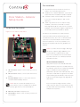
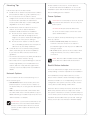
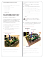
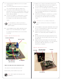
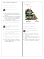
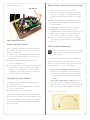
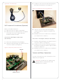
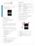
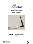
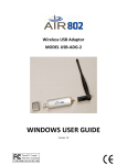
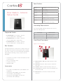
™
Door Station - Exterior
Setup Guide
Specifications
Dimensions (H x
W x D)
7.19” (183 mm) x 5.25” (133 mm) x 2.5”
(63.5 mm)
Weight
1.1 lbs. (.49 kg)
Shipping Weight
1.6 lbs. (.725 kg)
Network
10/100 BaseT Ethernet (preferred) or WiFi
(802.11 b/g/n)
Voltages
AC - 100V - 240V
DC - 12 - 24V, 15W
Contacts (2 sets)
DC: 48V
maximum operation (low voltage)
Relays (1)
AC: 36V, 2A
DC: 24V
maximum operation (low voltage)
Grounding Requirements
The following table indicates which power options
require an earth ground.
Supported Models
• C4-DSC-EN-BL Door Station - Exterior
AC, DC, POE & WiFi - Satin Black
Power Type
Earth Ground?
AC
Yes, required for safety.
Power over Ethernet (PoE)
No. Do not connect.
DC
Recommended; not required.
• C4-DSC-EN-SN Door Station - Exterior
AC, DC, POE & WiFi - Satin Nickel
• C4-DSC-EN-VB Door Station - Exterior
AC, DC, POE & WiFi - Venetian Bronze
Front Panel Description
Figure 1. Front Faceplate
Box Contents
5
1
4
5
2
Carefully unpack the Control4® Door Station from the
box and ensure that the following items are included
3
in the box. Contact your Control4 Dealer immediately
if any parts are missing or if any components are
damaged.
• Control4 Door Station - Exterior faceplate (model
4
C4-DSC-EN-xx)
• Two (2) mounting screws
• Security screw tool
• Warranty Card
Accessories
• Door Station Metal Back Box (C4-DSBB-M, sold
separately)
• Antenna Kit—WiFi/ZigBee 2.4 GHz, 26cm
(C4-AK-26cm, sold separately)
1
Camera. 640 x 480 wide angle. Used for Video
Intercom.
2
Call button. Used to call the person inside the
structure.
3
Speaker. Used for Audio and Video Intercom.
4
Screw holes (2). Used to screw the faceplate into
the exterior wall.
5
Microphones (2). Used for Audio and Video
Intercom.
• Antenna Kit—WiFi/ZigBee 2.4 GHz, 3m
(C4-AK-3M, sold separately)
1
Pre-Installation
™
1
Find the best exterior location for the Door
Station. See “Mounting Tips” below.
2
Door Station - Exterior
Setup Guide
Install the Door Station Back Box. See the Door
Station Back Box Installation Guide for details.
3
Determine which network and power options
to use (see “Network Options” and “Power
Options”).
4
(WiFi only). Before the Door Station is fully
installed, Control4 recommends to test the
WiFi signal strength in Composer Pro’s System
Inside Panel Description
Manager; a strong, robust signal is required. See
the Composer Pro User Guide for details.
Figure 2. Door Station, Inside Panel
This device uses an Ethernet or WiFi network
3
1
connection and can be powered using Power
over Ethernet (PoE), AC, or DC. A wired network
connection is recommended for the best Video
Intercom experience. If it is not possible to use
Ethernet, then please follow these guidelines for
wireless.
NOTES: (1) Video Intercom usage. Although
this device supports b/g/n, 802.11 b is not
recommended or supported for Video
Intercom. (2) Wireless-N is recommended
for Video Intercom. See “Wireless Network
Limitations” below.
Wireless Network Limitations
5
1
2
3
Many WiFi Access Points handle Multicasts
2
4
AC connection. Used to connect the wires for AC
(WiFi simultaneously sent to multiple devices,
for example, when the Door Station broadcasts
video to all stations) by slowing down
power.
transmission speed to the 1 Mb basic rate. This
DC connection. Used to connect the wires for DC
can cause overall WiFi congestion in the WiFi
power.
network during the broadcast. Video Intercom
Contacts/Relays. Used to connect the wires for
response times and images may degrade at
Control4 and third-party devices.
each device.
NOTE: Use the contacts and relays for non-
If a home requires a large number of WiFi
secure devices only. For example, don’t attach
Video Intercom devices, ensure that you have
security gate wires to this terminal block.
a robust WiFi network (possibly consisting of
multiple access points).
4
Ethernet connection. Supports PoE.
5
Reset Button. Used to reset or factory restore the
Door Station.
2
Mounting Tips
Please read the next sections, “Power Options”
> “Network and Power Installations” to choose an
Follow these tips for the best results.
installation option that works best with the system
1
before installing the Door Station.
Install the Door Station in a place where it will be
protected from water (e.g., rain, sprinklers, etc.).
2
Do not expose the Door Station to direct
Power Options
sunlight. If the sun hits the Door Station, Control4
3
recommends to purchase the Satin Nickel
CAUTION! Do not attempt to use PoE, AC, and
model (C4-DCS-EN-SN) to reduce fading and
DC power at the same time. Choose only one
degradation of the Door Station.
power option.
Find the best exterior location for the Door
Station. See the Door Station Back Box
ATTENTION! Ne pas tenter d’utiliser PoE,
Installation Guide for back box installation.
AC et DC en même temps. Choisir une seule
a
option d’alimentation.
Mount the Door Station where the video
camera is aimed at an average person’s
b
4
height so the person inside the building gets
The Door Station can be powered using one of these
a good view of the person calling in.
three (3) options:
Mount the Door Station so that the caller
• Power over Ethernet (PoE). The Ethernet
can comfortably speak into the microphone
network connection for the Door Station is
(about two (2) feet away or 60 cm).
provided through the PoE Injector. No additional
Control4 does not recommend using wireless
(WiFi) networking for an exterior installation.
wiring is needed.
• AC or DC. Used to power the Door Station when
If you must use WiFi, however, follow these
using an Ethernet (not PoE) or WiFi network
guidelines:
connection.
• The wireless access protocol (WAP) broadcast to
the exterior location must be strong.
• Use Composer Pro’s System Manager to test the
NOTE: Ethernet cable. Install the ferrite clamp
on the Ethernet cable inside the back box.
wireless signal after you’ve installed the Door
Station, and then verify that the signal works
Backlit Button Indicator
correctly. See the Composer Pro User Guide for
details.
The Door Station button’s light can be turned on or
off depending on what is required for the installation.
Network Options
The backlit button may make it easier to see the
The Door Station can be connected using one of
button when it is dark outside. Normally, the light on
these network types:
the button remains on or off depending on how it is
• Standard Ethernet. For best results, this is the
preferred option. Connect the Door Station to
configured in the system, however, it is also used to
convey device status during certain times.
the RJ-45 LAN port on using the RJ-45 Ethernet
cable.
• WiFi. The WiFi antenna will communicate with
When the device is first powered on, the button will
blink slowly until the device is ready to be used in
the LAN’s WAP. If the LAN has a WAP set up, no
the system. If the button continues to blink slowly for
additional wiring is needed except for power. See
over 3 minutes, then the device may be experiencing
“WiFi Antennas” for details.
a problem and should be factory restored. During a
factory restore process the button will blink rapidly.
IMPORTANT! (1) Control4 recommends to use
an Ethernet connection rather than WiFi for
the best communication with the Control4
system. (2) WiFi requires an antenna (sold
separately).
3
Power and Network Installations
To install the Door Station with Ethernet and AC
Choose one of these six (6) options to connect the
1
power:
(see Figure 4).
Door Station’s wiring:
• Ethernet with PoE (preferred)
2
Connect a ground wire from the Door Station to
one of the back box lugs (see Figure 12).
• Ethernet with AC
• Ethernet with DC
Plug the Ethernet cable into the Door Station
3
Connect a second earth-ground or house-ground
• WiFi with AC
wire from the second back box lug to the home.
• WiFi with DC
See “Grounding Requirements” for details about
earth grounding.
• WiFi with PoE
4
Connect the neutral (N) (-) and hot (L) (+) wires
to the AC power source for the Door Station
Option 1 (Preferred): Ethernet Connection with a
according to the national and local electrical
PoE Injector or a Third-Party Injector or Switch
codes.
This option sets up Ethernet with PoE.
TIP: The hot or ‘L’ (+) wire’s connector is
PoE injects electrical current into the Ethernet cable
closest to the bottom of the Door Station’s
using a PoE Injector - model #AC-POE1-B, or a
plate.
third-party PoE solution to provide the Door Station
with power and a network connection.
5
Your installation may require alternative wires and
the use of a terminal block. Strip the power wires
To install the Door Station with a PoE and Ethernet
to 1/4” on the end if necessary.
connection using a PoE Injector:
1
Plug the Ethernet cable into the Door Station
(see Figure 3).
2
See the section “Grounding Requirements” for
Figure 4. Ethernet with AC Power
AC Connections
(Hot and Load)
details about earth grounding.
Ethernet Cable
Figure 3. Ethernet with PoE Injector
Ethernet Connection
Ground Wire
Option 3: Ethernet Connection with DC Power
Option 2: Ethernet Connection with AC Power
This option sets up Ethernet and DC power.
This option sets up Ethernet and AC power.
To install the Door Station with Ethernet and DC
power:
4
1
2
Plug the Ethernet cable into the Door Station
To install the Door Station with WiFi and AC power:
(see Figure 5).
1
3
2
Connect a second earth-ground or house-ground
Connect a second earth-ground or house-
wire from the second back box lug to the home.
ground wire from the second back box lug to the
See “Grounding Requirements” for details about
home. See “Grounding Requirements” for details
earth grounding.
3
about earth grounding.
4
one of the back box lugs (see Figure 6).
Connect a ground wire from the Door Station to
one of the back box lugs (see Figure 12).
Connect a ground wire from the Door Station to
Connect the neutral (N) (-) and hot (L) (+) wires
Connect the negative (-) and positive (+) wires
to the AC power source for the Door Station
to the DC power source for the Door Station
according to the national and local electrical
according to the national and local electrical
codes.
codes.
TIP: The hot or ‘L’ (+) wire’s connector is
TIP: The positive (+) wire’s connector is
closest to the bottom of the Door Station’s
located on the bottom left side of the Door
plate.
Station’s plate.
4
5
Your installation may require alternative wires and
Your installation may require alternative wires
the use of a terminal block. Strip the power wires
and the use of a terminal block (see Figure
to 1/4” on the end if necessary.
5). Strip the power wires to 1/4” on the end if
5
Attach the antenna (3m or 26cm) to the Door
Station. See “WiFi Antenna Kit Installation” for
necessary.
details.
Figure 5. Ethernet with DC Power
6
(see Figure 6). Ensure that the wire doesn’t touch
Contacts and Relays
Ethernet Cable
Run the antenna wire through the back box hole
the back box.
7
Align the antenna vertically to the wall outside
the back box (26cm antenna) or run the antenna
through the wall (3m antenna). See “WiFi
Antennnas” for details.
Figure 6. WiFi with AC Power
Back Box
DC Connections
(Hot and Load)
AC Connections
(Hot and Load)
Antenna
Ground Wire
Option 4: WiFi Connection with AC Power
This option sets up WiFi and AC power.
Ensure that you have WiFi in the home.
Ground Wire
NOTE: WiFi requires an antenna (sold
separately).
5
Option 5: WiFi Connection with DC Power
Figure 7. WiFi with DC Power
Contacts and Relays
This option sets up WiFi and DC power.
Antenna
Ensure that you have WiFi in the home.
NOTE: WiFi requires an antenna (sold
separately).
To install the Door Station with WiFi and DC power:
1
(Recommended) Connect a ground wire from
the Door Station to one of the back box lugs (see
Figure 12).
2
(Recommended) Connect a second earth-ground
or house-ground wire from the second back box
lug to the home. See “Grounding Requirements”
for details about earth grounding.
3
Connect the negative (-) and positive (+) wires
DC Connections
(Hot and Load)
to the DC power source for the Door Station
Ground Wire
according to the national and local electrical
codes.
NOTE: The positive (+) wire’s connector is
located on the bottom left side of the Door
Station’s plate.
4
Option 6: WiFi Connection with PoE
This option sets up WiFi and PoE.
Ensure that you have WiFi in the home.
Your installation may require alternative wires and
NOTE: WiFi requires an antenna (sold
the use of a terminal block. Strip the power wires
separately).
to 1/4” on the end if necessary.
5
Attach the antenna (3m or 26cm) to the Door
Station. See “WiFi Antenna Kit Installation” for
details.
6
Run the antenna wire through the back box hole
(see Figure 12). Ensure that the wire doesn’t
To install the Door Station with WiFi and PoE:
1
(see Figure 8).
2
Align the antenna vertically to the wall outside
the back box (26cm antenna) or run the antenna
Attach the antenna (3m or 26cm) to the Door
Station. See “WiFi Antenna Kit Installation” for
touch the back box.
7
Plug the Ethernet cable into the Door Station
details.
3
Run the antenna wire through the back box hole
(see Figure 12). Ensure that the wire doesn’t
through the wall (3m antenna).
touch the back box.
4
Align the antenna vertically to the wall outside
the back box (26cm antenna) or run the antenna
through the wall (3m antenna).
6
Reset/Factory Restore the Door Station
Figure 8. WiFi with PoE
WiFi Antenna
To reset or factory restore the Door Station:
1
Unscrew the faceplate (top and bottom) and
pull the Door Station out from the back box just
enough to expose the Reset button (see Figure
2).
2
While powered press the Reset button on the
bottom of the Door Station to reset or restore
the Door Station.
• Quick press. Press to reset the Door Station.
• Long press. Press until the button on the
faceplate begins to blink rapidly. At that time, the
factory restore starts. This action restores the
Door Station to its factory default settings.
3
Ethernet and PoE Connection
When you are finished, insert the Door Station
back into the back box and screw the faceplate
back on.
Attach the Door Station
WiFi Antennas (Optional)
After the back box, all wiring, cables, and antennas
are installed, carefully insert the Door Station into the
NOTE: Control4 does not recommend to install
back box and the wall:
the Door Station using WiFi. The best option is
1
to use Ethernet.
Align the Door Station’s top and bottom screw
holes on the faceplate with the screw holes on
2
3
the back box.
Two (2) types of WiFi antenna kits are available for
Use the screws provided to attach the Door
purchase: 26cm (dipole, best performance) or 3m
Station to the back box.
(when you need to install the wire further away from
To prevent future moisture and dust from getting
the Door Station for a better WiFi signal).
inside the Door Station, make sure the rubber
gasket on the inside panel of the Door Station
• Antenna Kit—WiFi/ZigBee 2.4GHz, 26cm (C4-
completely covers and seals the Door Station’s
AK-26cm, sold separately). Recommended for
faceplate against the back box.
walls that do not have thick concrete or metal.
See Figure 9 and “WiFi Antenna Kit Installation”
Configure the Door Station
for details.
• Antenna Kit—WiFi/ZigBee 2.4GHz, 3m (C4-AK-
To configure the Door Station in Composer Pro:
3M, sold separately). Extend the range when
1
Open Composer Pro.
walls have thick concrete or metal. See Figure 10
2
Double-click the Door Station driver to add it to
and “WiFi Antenna Kit Installation” for details.
a room in the project.
3
Identify the device to the project.
Figure 9. 26cm Antenna Kit
(WiFi only) For your convenience, the Door Station
driver includes a meter to check WiFi signal strength.
Use System Manager in Composer Pro to configure
the WiFi parameters. See the Composer Pro User
Guide for details.
7
3
Figure 10. 3m Antenna Kit
Thread the other end of the antenna through the
back wall of the back box (see Figure 12).
Figure 12. Thread Antenna Through Back Box
WiFi Antenna Kit Installation (Optional)
Before you install the antenna:
1
Make sure the Door Station is assembled.
2
Make sure the Door Station back box is installed
in the wall. See the Door Station Back Box
Installation Guide for details.
4 Leave the other end of the antenna hanging
outside the back box. Adjust it vertically for the
best signal.
5
Carefully insert the Door Station into the back box
(see “Attach the Door Station”).
Antenna Kit—WiFi/ZigBee 2.4GHz, 26cm
(C4-AK-26cm)
1
Remove the antenna from its packaging.
2
Attach the antenna’s plug to the RSMA connector
on the Door Station (see Figure 11).
Figure 11. Antenna to RSMA Connector
Antenna
Antenna Kit— WiFi/ZigBee 2.4GHz, 3m (C4-AK-3M)
1
Attach the antenna’s plug to the RSMA connector
on the Door Station (see Figure 11).
2
Thread the other end of the antenna through the
back wall of the back box and through the wall as
needed (see Figure 12).
3
Carefully insert the Door Station into the back box
(see “Attach the Door Station”).
Contact and Relay Connections
You can connect devices to the contact ports or the
relay ports (see Figure 13).
CAUTION! Control4 does not support using
earth ground for Contacts as this could
damage the Door Station.
RSMA Connector
8
Figure 13. Contacts and Relays
Contacts
2
Using a small flat-blade screwdriver, insert the
screwdriver into the slot on the small block that
Relays
sits between the two rows of holes adjacent to
the port and push down firmly. The block will
depress.
3
Insert the wire. Ensure that the wire inserts all the
way into the hole.
4
Release the screwdriver.
Example Wiring
Connect to a Port
Figure 15. Relay Port: Normally Open (e.g., Doorbell)
The Door Station provides nine (9) connections for
contacts and relays: three (3) terminals for Contact
1, three (3) terminals for Contact 2, and three (3)
terminals for the relay (see Figure 14).
• Contact (2 sets). Terminal connector for one
(1) dry contact closure, logic input connection,
for gate control, etc. Provides power for small
devices (12 V), signal input (SIG), return path
(GND). The current, 100 mA, is shared across
both sets of contacts.
Troubleshooting
NOTE: Do not use contacts that are grounded.
The Door Station only supports non-grounded
contacts.
Boot Up
When the Door Station is booting up, if the button
blinks and does not stop after (3) minutes or longer,
• Relay (1). Terminal connector for one (1)
normally closed or normally opened switchable
connection for doorbell control (see Figure 15) or
gate control. The set contains a connection for
Normally Opened (NO), Normally Closed (NC),
and Common (COM).
there is a problem with the device and it will have to
be restored. See “Reset/Restore the Door Station”
later in this document.
Factory Restore
To restore the device to its default factory settings,
see “Reset/Restore the Door Station” later in this
document.
Figure 14. Contact/Relay Locations
Security Best Practices
The Control4 Door Station – Exterior is the first
smart Control4 device designed to be installed on
the outside of a dwelling. The Door Station has
connections for relays (to open doors, gates, etc.)
Contact 1
Contact 2
Relay
and contacts. If installed without the proper security
precautions, unauthorized access to the Door Station
could provide access to Ethernet signals, Control4
1
To attach the wires to the contacts or relay, select
signaling, and gate or door relays. Control4 advises
one of the large bottom-row holes (see Figure 13;
Control4 Dealers to be aware of these risks and take
notice that the top row holes are smaller than the
all necessary precautions depending on each specific
bottom-row holes).
installation you will be doing.
9
It is each Dealer’s sole responsibility to advise their
• Routing the Ethernet cable to the Door Station
customer at each installation of any security risks
through a secure, managed switch to limit data
specific to such installation. Control4 makes no
access from the Door Station.
claims, representations or warranties regarding the
security of this product and accepts no liability for
Dealers should take time to assure they are not
any security risk attendant to a specific installation.
creating an unforeseen security risk for the customer,
and any such risks should be discussed with the
1
The Door Station - Exterior ships standard with
customer prior to the installation.
security screws. Dealers are encouraged to
2
use these screws, or even substitute alternate
Carefully consider with your customer any contacts
security screws per the Dealer’s or customer’s
or relays before connecting them to the Door Station,
preference. Screw size is metric M3.5x.6-30L.
and what implications could arise if someone gained
Security gates or automatic doors should not
access to the rear of the Door Station.
be connected to the relay in the Door Station
3
if mounted in an unsecured area; such relays
Also, think about what could happen if someone
could be accessed in the event of a breach of
gained access to the Ethernet cable, and take
the device. Secure relay-driven devices should
necessary precautions to protect private customer
be connected to a more secure relay controller
information unless your customer is willing to assume
mounted behind a secure wall.
these risks. Making available the proper security
Security devices, for example numeric keypads,
protections to a customer for their residence is the
should not be connected to the contact sensors
responsibility of the Control4 Installer.
in the Door Station if mounted in an unsecured
area; such devices could be accessed in the event
of a breach of the device. Security-sensitive
devices should be connected to more secure
contacts mounted behind a secure wall.
4
Although the best video performance will be
enabled by Ethernet connectivity, unauthorized
access to the Door Station could provide
access to the dwelling’s Ethernet network and
corresponding personal data.
There are alternatives to mitigate this risk. The
Dealer should consider the following options:
• Running Control4 on an isolated LAN from PCs
on the network would limit exposure to personal
data.
• Running MAC address filtering on the router
or switch to force a hacker to spoof the Door
Station’s MAC address to gain access to the LAN.
• Configuring the Door Station as WiFi instead of
Ethernet would allow the Dealer to use robust
WiFi security protocols, for example, WPA.
NOTE: WiFi signals must be very strong and
Warnings
WARNING! To avoid bodily harm, understand
and follow these safety precautions before
operating this Door Station:
- Using worn-out or damaged power cords
may result in electric shock or fire.
- Always contact an authorized Control4
service provider for assistance if any repair or
adjustment is required.
Avertissement! Pour éviter des dommages
physiques, comprenez et suivez ces mesures
de sécurité avant d’actionner station de porte
Control4® sans fil:
- Utilisant usé ou endommagé les cordons de
secteur peuvent avoir comme conséquence
la décharge électrique ou le feu.
- Entrez en contact avec toujours un
fournisseur des services Control4® autorisé
pour l’aide si n’importe quelle réparation ou
ajustement est exigée.
stable to support Video Intercom.
IMPORTANT! Improper use or installation can
cause LOSS/DAMAGE OF PROPERTY.
10
Important! L’utilisation ou l’installation inexacte
peut causer LOSS/DAMAGE DE PROPRIÉTÉ.
IMPORTANT! Using this product in a manner
other than outlined in this document voids
your warranty. Further, Control4 is NOT liable
for any damage incurred with the misuse of
this product. See “Warranty.”
Important! Utilisant ce produit en quelque
sorte autre que décrit dans ce document vide
votre garantie. De plus, Control4 n’est pas
responsable d’aucun dommage encouru avec
l’abus de ce produit. Voyez que «Warranty.»
WARNING! Before you install the Door Station
switch off the circuit breaker or remove the
fuse from the fuse box.
AVERTISSEMENT! Pour l’endroit où vous
installez station de porte, coupez le disjoncteur
ou enlevez le fusible de la boîte de fusible.
IMPORTANT! Before you can complete these
instructions below, you must have a Door
Station back box installed according to the
documentation provided in the back box kit.
See “Accessories” for details.
Important! En coupant l’ouverture pour la
boîte de mur, ne coupez pas l’ouverture trop
grande. Soyez conservateur et agrandissezavec précaution la comme nécessaire. Voyez
que <<Accessories>>.
Regulatory/Safety Information
To review regulatory information for your particular
Control4 products, see the information located on
the Control4 website at: http://www.control4.com/
regulatory/.
Warranty
Limited 2-year Warranty. Go to http://www.control4.
com/warranty for details.
control4.com |
™
11
©2013 Control4. All rights reserved. Control4, the Control4 logo, the Control4 iQ logo and the Control4 certified logo are registered trademarks or trademarks of Control4 Corporation in
the United States and/or other countries. All other names and brands may be claimed as the property of their respective owners. 200-00243, Rev. F 11/22/13 BN