1
CÓPIA NÃO CONTROLADA
®
A166/A187/A189
SERVICE MANUAL
PN: RCSM2003
RICOH GROUP COMPANIES
CÓPIA NÃO CONTROLADA
CÓPIA NÃO CONTROLADA
®
®
®
A166/A187/A189
SERVICE MANUAL
RICOH GROUP COMPANIES
CÓPIA NÃO CONTROLADA
CÓPIA NÃO CONTROLADA
CÓPIA NÃO CONTROLADA
CÓPIA NÃO CONTROLADA
A166/A187/A189
SERVICE MANUAL
PN: RCSM2003
CÓPIA NÃO CONTROLADA
CÓPIA NÃO CONTROLADA
CÓPIA NÃO CONTROLADA
CÓPIA NÃO CONTROLADA
It is the reader's responsibility when discussing the information contained within this
document to maintain a level of confidentiality that is in the best interest of Ricoh
Corporation and its member companies.
NO PART OF THIS DOCUMENT MAY BE REPRODUCED IN ANY
FASHION AND DISTRIBUTED WITHOUT THE PRIOR
PERMISSION OF RICOH CORPORATION.
All product names, domain names or product illustrations, including desktop images,
used in this document are trademarks, registered trademarks or the property of their
respective companies.
They are used throughout this book in an informational or editorial fashion only and for
the benefit of such companies. No such use, or the use of any trade name, or web
site is intended to convey endorsement or other affiliation with Ricoh products.
2000 RICOH Corporation. All rights reserved.
CÓPIA NÃO CONTROLADA
CÓPIA NÃO CONTROLADA
CÓPIA NÃO CONTROLADA
CÓPIA NÃO CONTROLADA
WARNING
The Service Manual contains information
regarding service techniques, procedures,
processes and spare parts of office equipment
distributed by Ricoh Corporation. Users of this
manual should be either service trained or certified
by successfully completing a Ricoh Technical
Training Program.
Untrained and uncertified users utilizing
information contained in this service manual to
repair or modify Ricoh equipment risk personal
injury, damage to property or loss of warranty
protection.
Ricoh Corporation
CÓPIA NÃO CONTROLADA
CÓPIA NÃO CONTROLADA
CÓPIA NÃO CONTROLADA
CÓPIA NÃO CONTROLADA
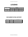
LEGEND
PRODUCT CODE
A166
A187
A189
GESTETNER
2703
2703D
2703DE
COMPANY
RICOH
Aficio 2003
Aficio 2103
Aficio 2203
SAVIN
SDC103
SDC103A
SDC103E
DOCUMENTATION HISTORY
REV. NO.
*
DATE
10/96
COMMENTS
Original Printing
CÓPIA NÃO CONTROLADA
CÓPIA NÃO CONTROLADA
CÓPIA NÃO CONTROLADA
CÓPIA NÃO CONTROLADA
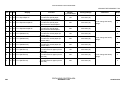
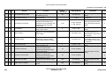
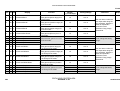
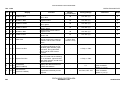
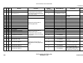
Table of Contents
OVERALL MACHINE INFORMATION
1. SPECIFICATIONS . . . . . . . . . . . . . . . . . . . . . . . . . . . . . . . . . . . . . . 1-1
1.1 MACHINE CONFIGURATION . . . . . . . . . . . . . . . . . . . . . . . . . . . . . . . . . . . . . 1-1
1.2 GENERAL SPECIFICATIONS. . . . . . . . . . . . . . . . . . . . . . . . . . . . . . . . . . . . . 1-2
1.3 DETECTABLE ORIGINAL SIZE BY PLATEN/ARDF . . . . . . . . . . . . . . . . . . . 1-6
1.4 COPY PAPER SIZE . . . . . . . . . . . . . . . . . . . . . . . . . . . . . . . . . . . . . . . . . . . . 1-7
1.5 PAPER SIZES AVAILABLE WITH APS . . . . . . . . . . . . . . . . . . . . . . . . . . . . . 1-8
1.6 NOISE EMISSION . . . . . . . . . . . . . . . . . . . . . . . . . . . . . . . . . . . . . . . . . . . . . . 1-9
1.7 POWER CONSUMPTION . . . . . . . . . . . . . . . . . . . . . . . . . . . . . . . . . . . . . . . 1-10
1.8 DISPLAY EDITOR SPECIFICATION . . . . . . . . . . . . . . . . . . . . . . . . . . . . . . 1-10
2. MACHINE CONFIGURATION . . . . . . . . . . . . . . . . . . . . . . . . . . . 1-11
2.1 COPY PROCESSES AROUND THE DRUM AND BELT . . . . . . . . . . . . . . . 1-11
3. MAJOR UNIT OVERVIEW . . . . . . . . . . . . . . . . . . . . . . . . . . . . . . 1-13
4. PARTS LAYOUT . . . . . . . . . . . . . . . . . . . . . . . . . . . . . . . . . . . . . . 1-16
4.1 MECHANICAL COMPONENT LAYOUT
. . . . . . . . . . . . . . . . . . . . . . . . . . 1-16
4.2 PCB (A166/A187 COPIERS) . . . . . . . . . . . . . . . . . . . . . . . . . . . . . . . . . . . . 1-17
4.3 PCB (A189 COPIER) . . . . . . . . . . . . . . . . . . . . . . . . . . . . . . . . . . . . . . . . . . 1-18
4.4 SOLENOIDS AND CLUTCHES . . . . . . . . . . . . . . . . . . . . . . . . . . . . . . . . . . 1-19
4.5 SWITCHES AND HEATERS . . . . . . . . . . . . . . . . . . . . . . . . . . . . . . . . . . . . 1-20
4.6 SENSORS . . . . . . . . . . . . . . . . . . . . . . . . . . . . . . . . . . . . . . . . . . . . . . . . . . 1-21
4.7 MOTORS . . . . . . . . . . . . . . . . . . . . . . . . . . . . . . . . . . . . . . . . . . . . . . . . . . . 1-22
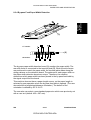
4.8 DRIVE LAYOUT
. . . . . . . . . . . . . . . . . . . . . . . . . . . . . . . . . . . . . . . . . . . . . 1-23
4.9 FANS AND AIR FLOW
. . . . . . . . . . . . . . . . . . . . . . . . . . . . . . . . . . . . . . . . 1-24
4.10 COUNTERS (A166/A187 COPIERS)
4.11 COUNTER (A189 COPIER)
. . . . . . . . . . . . . . . . . . . . . . . . . . . . 1-25
. . . . . . . . . . . . . . . . . . . . . . . . . . . . . . . . . . . 1-26
5. ELECTRICAL COMPONENT LIST . . . . . . . . . . . . . . . . . . . . . . . . 1-27
5.1 PRINTED CIRCUIT BOARDS . . . . . . . . . . . . . . . . . . . . . . . . . . . . . . . . . . . . 1-27
5.2 SOLENOIDS . . . . . . . . . . . . . . . . . . . . . . . . . . . . . . . . . . . . . . . . . . . . . . . . . 1-28
5.3 CLUTCHES . . . . . . . . . . . . . . . . . . . . . . . . . . . . . . . . . . . . . . . . . . . . . . . . . . 1-28
SM
i
CÓPIA NÃO CONTROLADA
A166/A187/A189
CÓPIA NÃO CONTROLADA
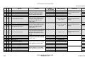
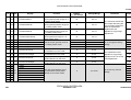
5.4 SWITCHES . . . . . . . . . . . . . . . . . . . . . . . . . . . . . . . . . . . . . . . . . . . . . . . . . . 1-29
5.5 LAMPS. . . . . . . . . . . . . . . . . . . . . . . . . . . . . . . . . . . . . . . . . . . . . . . . . . . . . . 1-29
5.6 HEATERS . . . . . . . . . . . . . . . . . . . . . . . . . . . . . . . . . . . . . . . . . . . . . . . . . . . 1-30
5.7 THERMISTORS. . . . . . . . . . . . . . . . . . . . . . . . . . . . . . . . . . . . . . . . . . . . . . . 1-30
5.8 THERMOFUSES . . . . . . . . . . . . . . . . . . . . . . . . . . . . . . . . . . . . . . . . . . . . . . 1-30
5.9 THERMOSTAT . . . . . . . . . . . . . . . . . . . . . . . . . . . . . . . . . . . . . . . . . . . . . . . 1-30
5.10 SENSORS . . . . . . . . . . . . . . . . . . . . . . . . . . . . . . . . . . . . . . . . . . . . . . . . . . 1-31
5.11 MOTORS . . . . . . . . . . . . . . . . . . . . . . . . . . . . . . . . . . . . . . . . . . . . . . . . . . . 1-32
5.12 FAN MOTORS . . . . . . . . . . . . . . . . . . . . . . . . . . . . . . . . . . . . . . . . . . . . . . . 1-32
5.13 COUNTER . . . . . . . . . . . . . . . . . . . . . . . . . . . . . . . . . . . . . . . . . . . . . . . . . . 1-33
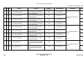
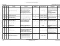
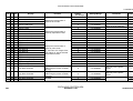
DETAILED DESCRIPTIONS
1. PROCESS CONTROL . . . . . . . . . . . . . . . . . . . . . . . . . . . . . . . . . . . 2-1
1.1 OVERVIEW . . . . . . . . . . . . . . . . . . . . . . . . . . . . . . . . . . . . . . . . . . . . . . . . . . 2-1
1.2 PROCESS CONTROL MEASUREMENT TIMING . . . . . . . . . . . . . . . . . . . . . 2-3
1.3 POTENTIAL CONTROL (LATENT IMAGE CONTROL) . . . . . . . . . . . . . . . . . 2-4
1.3.1 Concept . . . . . . . . . . . . . . . . . . . . . . . . . . . . . . . . . . . . . . . . . . . . . . . . . . 2-4
1.3.2 Process Control Self Check . . . . . . . . . . . . . . . . . . . . . . . . . . . . . . . . . . . 2-5
1.3.3 Process Control Self Check Procedure . . . . . . . . . . . . . . . . . . . . . . . . . 2-6
1.3.4 Drum Potential Sensor Calibration . . . . . . . . . . . . . . . . . . . . . . . . . . . . . 2-7
1.3.5 Vsg Calibration. . . . . . . . . . . . . . . . . . . . . . . . . . . . . . . . . . . . . . . . . . . . . 2-8
1.3.6 Writing the Gradation Pattern . . . . . . . . . . . . . . . . . . . . . . . . . . . . . . . . . 2-8
1.3.7 Gradation Pattern Potential Detection . . . . . . . . . . . . . . . . . . . . . . . . . . . 2-8
1.3.8 Gradation Pattern Development . . . . . . . . . . . . . . . . . . . . . . . . . . . . . . . 2-9
1.3.9 Gradation Pattern Density Detection . . . . . . . . . . . . . . . . . . . . . . . . . . . . 2-9
1.3.10 Development Potential Calculation . . . . . . . . . . . . . . . . . . . . . . . . . . . . 2-9
1.3.11 VD, VB, VL Selection (Pointer Table) . . . . . . . . . . . . . . . . . . . . . . . . . . 2-10
1.3.12 VG, VB, ILD Correction . . . . . . . . . . . . . . . . . . . . . . . . . . . . . . . . . . . . . 2-10
1.3.13 Confirmation Procedure . . . . . . . . . . . . . . . . . . . . . . . . . . . . . . . . . . . 2-10
1.3.14 Potential Control in Abnormal Sensor Conditions . . . . . . . . . . . . . . . . 2-11
1.3.15 Abnormal Sensor Conditions (SC) . . . . . . . . . . . . . . . . . . . . . . . . . . . . 2-14
A166/A187/A189
ii
CÓPIA NÃO CONTROLADA
SM
CÓPIA NÃO CONTROLADA
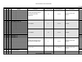
1.4 TONER SUPPLY CONTROL . . . . . . . . . . . . . . . . . . . . . . . . . . . . . . . . . . . . 2-15
1.4.1 Toner Supply Control Method . . . . . . . . . . . . . . . . . . . . . . . . . . . . . . . . 2-15
1.4.2 Fuzzy Control Mode . . . . . . . . . . . . . . . . . . . . . . . . . . . . . . . . . . . . . . . 2-15
1.4.3 Fixed Supply Mode . . . . . . . . . . . . . . . . . . . . . . . . . . . . . . . . . . . . . . . . 2-17
1.4.4 Toner Supply in Abnormal Sensor Conditions . . . . . . . . . . . . . . . . . . . . 2-17
1.4.5 Toner End Detection . . . . . . . . . . . . . . . . . . . . . . . . . . . . . . . . . . . . . . . 2-18
1.4.6 Developer Agitation . . . . . . . . . . . . . . . . . . . . . . . . . . . . . . . . . . . . . . . . 2-20
2. DRUM UNIT . . . . . . . . . . . . . . . . . . . . . . . . . . . . . . . . . . . . . . . . . 2-24
2.1 OVERVIEW . . . . . . . . . . . . . . . . . . . . . . . . . . . . . . . . . . . . . . . . . . . . . . . . . . 2-24
2.1.1 OPC Drum Characteristics. . . . . . . . . . . . . . . . . . . . . . . . . . . . . . . . . . . 2-24
2.2 MECHANISMS
. . . . . . . . . . . . . . . . . . . . . . . . . . . . . . . . . . . . . . . . . . . . . . 2-25
2.2.1 Drive Mechanism . . . . . . . . . . . . . . . . . . . . . . . . . . . . . . . . . . . . . . . . . . 2-25
2.2.2 Drum Charge . . . . . . . . . . . . . . . . . . . . . . . . . . . . . . . . . . . . . . . . . . . . 2-26
2.2.3 Drum Cleaning . . . . . . . . . . . . . . . . . . . . . . . . . . . . . . . . . . . . . . . . . . . 2-27
2.2.4 Quenching . . . . . . . . . . . . . . . . . . . . . . . . . . . . . . . . . . . . . . . . . . . . . . . 2-28
3. SCANNER UNIT . . . . . . . . . . . . . . . . . . . . . . . . . . . . . . . . . . . . . . 2-29
3.1 OVERVIEW . . . . . . . . . . . . . . . . . . . . . . . . . . . . . . . . . . . . . . . . . . . . . . . . . . 2-29
3.2 SCANNER . . . . . . . . . . . . . . . . . . . . . . . . . . . . . . . . . . . . . . . . . . . . . . . . . . 2-30
3.3 SCANNER DRIVE . . . . . . . . . . . . . . . . . . . . . . . . . . . . . . . . . . . . . . . . . . . . 2-31
3.4 COLOR CCD . . . . . . . . . . . . . . . . . . . . . . . . . . . . . . . . . . . . . . . . . . . . . . . . 2-32
3.5 WHITE PLATE SCANNING . . . . . . . . . . . . . . . . . . . . . . . . . . . . . . . . . . . . . 2-33
3.6 SCANNER IPU BOARD . . . . . . . . . . . . . . . . . . . . . . . . . . . . . . . . . . . . . . . . 2-33
3.7 ORIGINAL SIZE DETECTION . . . . . . . . . . . . . . . . . . . . . . . . . . . . . . . . . . . 2-34
3.8 OTHERS . . . . . . . . . . . . . . . . . . . . . . . . . . . . . . . . . . . . . . . . . . . . . . . . . . . . 2-36
4. IMAGE PROCESSING. . . . . . . . . . . . . . . . . . . . . . . . . . . . . . . . . . 2-38
4.1 OVERVIEW . . . . . . . . . . . . . . . . . . . . . . . . . . . . . . . . . . . . . . . . . . . . . . . . . . 2-38
4.2 SCANNER SECTION BLOCK DIAGRAM . . . . . . . . . . . . . . . . . . . . . . . . . . . 2-39
4.3 SCANNER SECTION . . . . . . . . . . . . . . . . . . . . . . . . . . . . . . . . . . . . . . . . . . 2-40
4.3.1 Photoelectric Conversion . . . . . . . . . . . . . . . . . . . . . . . . . . . . . . . . . . . . 2-40
4.3.2 Signal Processing . . . . . . . . . . . . . . . . . . . . . . . . . . . . . . . . . . . . . . . . . 2-40
4.3.3 A/D Conversion . . . . . . . . . . . . . . . . . . . . . . . . . . . . . . . . . . . . . . . . . . . 2-40
4.3.4 Shading Circuit . . . . . . . . . . . . . . . . . . . . . . . . . . . . . . . . . . . . . . . . . . . 2-41
SM
iii
CÓPIA NÃO CONTROLADA
A166/A187/A189
CÓPIA NÃO CONTROLADA
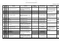
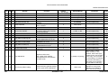
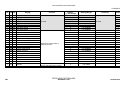
4.3.5 D/A Conversion . . . . . . . . . . . . . . . . . . . . . . . . . . . . . . . . . . . . . . . . . . . 2-43
4.3.6 Scan Line Correction . . . . . . . . . . . . . . . . . . . . . . . . . . . . . . . . . . . . . . . 2-43
4.4 IPU SECTION BLOCK DIAGRAM. . . . . . . . . . . . . . . . . . . . . . . . . . . . . . . . . 2-44
4.5 IPU SECTION . . . . . . . . . . . . . . . . . . . . . . . . . . . . . . . . . . . . . . . . . . . . . . . . 2-45
4.5.1 Picture Element Correction and Scanner Gamma Correction . . . . . . . . 2-45
4.5.2 ACS (Auto Color Selection) . . . . . . . . . . . . . . . . . . . . . . . . . . . . . . . . . 2-47
4.5.3 Auto Letter/Photo Separation. . . . . . . . . . . . . . . . . . . . . . . . . . . . . . . . . 2-48
4.5.4 Filtering and Color Conversion. . . . . . . . . . . . . . . . . . . . . . . . . . . . . . . . 2-50
4.5.5 Main Scan Magnification . . . . . . . . . . . . . . . . . . . . . . . . . . . . . . . . . . . . 2-57
4.5.6 Gamma Correction (Printer Gamma) . . . . . . . . . . . . . . . . . . . . . . . . . . 2-58
4.5.7 Gradation Treatment (Dither Processing) . . . . . . . . . . . . . . . . . . . . . . . 2-61
4.6 CPU . . . . . . . . . . . . . . . . . . . . . . . . . . . . . . . . . . . . . . . . . . . . . . . . . . . . . . . . 2-62
4.7 EXTENDED IPU (EDIT MACHINE ONLY) . . . . . . . . . . . . . . . . . . . . . . . . . . 2-62
4.8 OTHERS . . . . . . . . . . . . . . . . . . . . . . . . . . . . . . . . . . . . . . . . . . . . . . . . . . . . 2-64
4.8.1 Interface . . . . . . . . . . . . . . . . . . . . . . . . . . . . . . . . . . . . . . . . . . . . . . . . . 2-64
4.8.2 IPU Board Test . . . . . . . . . . . . . . . . . . . . . . . . . . . . . . . . . . . . . . . . . . . 2-64
5. LASER EXPOSURE . . . . . . . . . . . . . . . . . . . . . . . . . . . . . . . . . . . 2-65
5.1 OVERVIEW . . . . . . . . . . . . . . . . . . . . . . . . . . . . . . . . . . . . . . . . . . . . . . . . . . 2-65
5.2 OPTICAL PATH . . . . . . . . . . . . . . . . . . . . . . . . . . . . . . . . . . . . . . . . . . . . . . 2-66
5.2.1 Overview . . . . . . . . . . . . . . . . . . . . . . . . . . . . . . . . . . . . . . . . . . . . . . . . 2-66
5.2.2 Cylindrical Lens . . . . . . . . . . . . . . . . . . . . . . . . . . . . . . . . . . . . . . . . . . . 2-67
5.2.3 Polygon Mirror . . . . . . . . . . . . . . . . . . . . . . . . . . . . . . . . . . . . . . . . . . . . 2-67
5.2.4 F-theta Lenses and the BTL
. . . . . . . . . . . . . . . . . . . . . . . . . . . . . . . . 2-68
5.2.5 Laser Synchronizing Detector Boards . . . . . . . . . . . . . . . . . . . . . . . . . 2-69
5.3 GRADATION CONTROL (LASER POWER MODULATION) . . . . . . . . . . . 2-70
5.4 AUTO POWER CONTROL (APC) . . . . . . . . . . . . . . . . . . . . . . . . . . . . . . . . 2-71
5.5 LD SAFETY SWITCHES . . . . . . . . . . . . . . . . . . . . . . . . . . . . . . . . . . . . . . . 2-72
6. DEVELOPMENT UNIT. . . . . . . . . . . . . . . . . . . . . . . . . . . . . . . . . . 2-73
6.1 OVERVIEW . . . . . . . . . . . . . . . . . . . . . . . . . . . . . . . . . . . . . . . . . . . . . . . . . . 2-73
6.2 MECHANISMS . . . . . . . . . . . . . . . . . . . . . . . . . . . . . . . . . . . . . . . . . . . . . . . 2-74
6.2.1 Revolver Development Mechanism . . . . . . . . . . . . . . . . . . . . . . . . . . . . 2-74
A166/A187/A189
iv
CÓPIA NÃO CONTROLADA
SM
CÓPIA NÃO CONTROLADA
6.2.2 Development Mechanism . . . . . . . . . . . . . . . . . . . . . . . . . . . . . . . . . . . 2-77
6.2.3 Toner Mixing . . . . . . . . . . . . . . . . . . . . . . . . . . . . . . . . . . . . . . . . . . . . . 2-78
6.2.4 Developer Mixing . . . . . . . . . . . . . . . . . . . . . . . . . . . . . . . . . . . . . . . . . 2-81
6.2.5 Development Roller Drive . . . . . . . . . . . . . . . . . . . . . . . . . . . . . . . . . . . 2-84
6.2.6 Development Bias . . . . . . . . . . . . . . . . . . . . . . . . . . . . . . . . . . . . . . . . . 2-85
6.2.7 Toner Cartridge Detection . . . . . . . . . . . . . . . . . . . . . . . . . . . . . . . . . . 2-86
6.2.8 Color Toner Positioning Pin . . . . . . . . . . . . . . . . . . . . . . . . . . . . . . . . . 2-87
6.2.9 Revolver Positioning . . . . . . . . . . . . . . . . . . . . . . . . . . . . . . . . . . . . . . . 2-88
7. TRANSFER BELT UNIT . . . . . . . . . . . . . . . . . . . . . . . . . . . . . . . . 2-93
7.1 OVERVIEW . . . . . . . . . . . . . . . . . . . . . . . . . . . . . . . . . . . . . . . . . . . . . . . . . . 2-93
7.2 LAYOUT
. . . . . . . . . . . . . . . . . . . . . . . . . . . . . . . . . . . . . . . . . . . . . . . . . . . 2-94
7.3 BELT TRANSFER . . . . . . . . . . . . . . . . . . . . . . . . . . . . . . . . . . . . . . . . . . . . . 2-95
7.3.1 Transfer Belt Drive . . . . . . . . . . . . . . . . . . . . . . . . . . . . . . . . . . . . . . . . 2-95
7.3.2 Transfer Belt Release Mechanism . . . . . . . . . . . . . . . . . . . . . . . . . . . 2-101
7.3.3 Belt Transfer Bias
. . . . . . . . . . . . . . . . . . . . . . . . . . . . . . . . . . . . . . . 2-102
7.3.4 Belt Mark Detection . . . . . . . . . . . . . . . . . . . . . . . . . . . . . . . . . . . . . . . 2-103
7.3.5 Transfer Belt Cleaning . . . . . . . . . . . . . . . . . . . . . . . . . . . . . . . . . . . . 2-104
7.3.6 Toner Collection . . . . . . . . . . . . . . . . . . . . . . . . . . . . . . . . . . . . . . . . . 2-105
7.3.7 Belt Lubricant Mechanism . . . . . . . . . . . . . . . . . . . . . . . . . . . . . . . . . 2-106
7.3.8 PTL (Pre-transfer Lamp) . . . . . . . . . . . . . . . . . . . . . . . . . . . . . . . . . . . 2-107
7.4 PAPER TRANSFER
. . . . . . . . . . . . . . . . . . . . . . . . . . . . . . . . . . . . . . . . . 2-108
7.4.1 Paper Transfer Bias . . . . . . . . . . . . . . . . . . . . . . . . . . . . . . . . . . . . . . . 2-108
7.4.2 Paper Discharge . . . . . . . . . . . . . . . . . . . . . . . . . . . . . . . . . . . . . . . . . 2-110
7.4.3 Uniform Transfer Belt Charge . . . . . . . . . . . . . . . . . . . . . . . . . . . . . . . 2-110
8. PAPER FEED AND REGISTRATION . . . . . . . . . . . . . . . . . . . . 2-111
8.1 OVERVIEW . . . . . . . . . . . . . . . . . . . . . . . . . . . . . . . . . . . . . . . . . . . . . . . . . 2-111
8.2 PAPER TRAY MECHANISM (A166 COPIER ONLY) . . . . . . . . . . . . . . . . 2-112
8.2.1 Paper Feed Drive Mechanism . . . . . . . . . . . . . . . . . . . . . . . . . . . . . . . 2-112
8.2.2 Paper Lift Mechanism
. . . . . . . . . . . . . . . . . . . . . . . . . . . . . . . . . . . . 2-114
8.2.3 Paper End Detection . . . . . . . . . . . . . . . . . . . . . . . . . . . . . . . . . . . . . . 2-115
8.2.4 Paper Size Detection
. . . . . . . . . . . . . . . . . . . . . . . . . . . . . . . . . . . . 2-116
8.2.5 Vertical Transport Mechanism . . . . . . . . . . . . . . . . . . . . . . . . . . . . . . 2-117
SM
v
CÓPIA NÃO CONTROLADA
A166/A187/A189
CÓPIA NÃO CONTROLADA
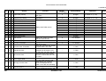
8.2.6 Side Fence Double-stopper Mechanism . . . . . . . . . . . . . . . . . . . . . . . 2-118
8.3 BY-PASS FEED. . . . . . . . . . . . . . . . . . . . . . . . . . . . . . . . . . . . . . . . . . . . . . 2-119
8.3.1 By-pass Feed Table Mechanism . . . . . . . . . . . . . . . . . . . . . . . . . . . . 2-119
8.3.2 Paper Feed . . . . . . . . . . . . . . . . . . . . . . . . . . . . . . . . . . . . . . . . . . . . . 2-120
8.3.3 Paper End Detection . . . . . . . . . . . . . . . . . . . . . . . . . . . . . . . . . . . . . . 2-120
8.3.4 By-pass Feed Paper Width Detection . . . . . . . . . . . . . . . . . . . . . . . . 2-121
8.3.5 Pick-up Roller Pressure Mechanism . . . . . . . . . . . . . . . . . . . . . . . . . . 2-122
8.4 REGISTRATION DRIVE MECHANISM . . . . . . . . . . . . . . . . . . . . . . . . . . . 2-123
9. PAPER TRANSPORT AND IMAGE FUSING . . . . . . . . . . . . . . . 2-124
9.1 PAPER TRANSPORT UNIT . . . . . . . . . . . . . . . . . . . . . . . . . . . . . . . . . . . 2-124
9.1.1 Drive Mechanism . . . . . . . . . . . . . . . . . . . . . . . . . . . . . . . . . . . . . . . . . 2-124
9.1.2 Transport Mechanism . . . . . . . . . . . . . . . . . . . . . . . . . . . . . . . . . . . . . 2-124
9.2 FUSING UNIT OVERVIEW . . . . . . . . . . . . . . . . . . . . . . . . . . . . . . . . . . . . 2-125
9.3 FUSING UNIT . . . . . . . . . . . . . . . . . . . . . . . . . . . . . . . . . . . . . . . . . . . . . . . 2-126
9.3.1 Fusing Temperature Control . . . . . . . . . . . . . . . . . . . . . . . . . . . . . . . . 2-126
9.3.2 Fusing Pressure Mechanism . . . . . . . . . . . . . . . . . . . . . . . . . . . . . . . 2-127
9.3.3 Oil Supply Mechanism . . . . . . . . . . . . . . . . . . . . . . . . . . . . . . . . . . . . 2-128
9.3.4 Cleaning Mechanism . . . . . . . . . . . . . . . . . . . . . . . . . . . . . . . . . . . . . . 2-129
9.3.5 Fusing Drive Release Mechanism . . . . . . . . . . . . . . . . . . . . . . . . . . . 2-130
9.4 JUNCTION GATE AND PAPER EXIT . . . . . . . . . . . . . . . . . . . . . . . . . . . . 2-131
9.4.1 Paper Exit . . . . . . . . . . . . . . . . . . . . . . . . . . . . . . . . . . . . . . . . . . . . . . 2-131
9.4.2 Junction Gate Mechanism (A187/A189 copiers only)
. . . . . . . . . . . . 2-132
9.4.3 Paper Exit Door (A187/A189 copiers only) . . . . . . . . . . . . . . . . . . . . . 2-133
10. DUPLEX UNIT . . . . . . . . . . . . . . . . . . . . . . . . . . . . . . . . . . . . . 2-134
10.1 OVERVIEW . . . . . . . . . . . . . . . . . . . . . . . . . . . . . . . . . . . . . . . . . . . . . . . . 2-134
10.2 DUPLEX UNIT MECHANISMS (A187/A189 copiers only) . . . . . . . . . . . . 2-135
10.2.1 Drive Mechanism . . . . . . . . . . . . . . . . . . . . . . . . . . . . . . . . . . . . . . . . 2-135
10.2.2 Duplex Paper Path . . . . . . . . . . . . . . . . . . . . . . . . . . . . . . . . . . . . . . 2-136
10.2.3 Duplex Entrance To Duplex Tray
10.2.4 Jogger Mechanism
. . . . . . . . . . . . . . . . . . . . . . . . . . 2-137
. . . . . . . . . . . . . . . . . . . . . . . . . . . . . . . . . . . . . 2-138
10.2.5 Paper Feed from the Duplex Tray . . . . . . . . . . . . . . . . . . . . . . . . . . 2-139
10.2.6 Paper Feed System . . . . . . . . . . . . . . . . . . . . . . . . . . . . . . . . . . . . . 2-140
A166/A187/A189
vi
CÓPIA NÃO CONTROLADA
SM
CÓPIA NÃO CONTROLADA
11. SYSTEM CONFIGURATION . . . . . . . . . . . . . . . . . . . . . . . . . . 2-141
11.1 BLOCK DIAGRAM. . . . . . . . . . . . . . . . . . . . . . . . . . . . . . . . . . . . . . . . . . . 2-141
11.2 COMMAND SEQUENCE . . . . . . . . . . . . . . . . . . . . . . . . . . . . . . . . . . . . . 2-142
11.2.1 Normal Copy Mode . . . . . . . . . . . . . . . . . . . . . . . . . . . . . . . . . . . . . . 2-142
11.2.2 Edit Mode . . . . . . . . . . . . . . . . . . . . . . . . . . . . . . . . . . . . . . . . . . . . . . 2-143
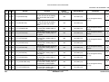
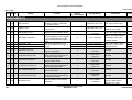
INSTALLATION
1. INSTALLATION REQUIREMENTS . . . . . . . . . . . . . . . . . . . . . . . . 3-1
1.1 DIMENSIONS . . . . . . . . . . . . . . . . . . . . . . . . . . . . . . . . . . . . . . . . . . . . . . . . . 3-1
1.2 ENVIRONMENT . . . . . . . . . . . . . . . . . . . . . . . . . . . . . . . . . . . . . . . . . . . . . . . 3-2
1.2.1 Environmental Requirements. . . . . . . . . . . . . . . . . . . . . . . . . . . . . . . . . . 3-2
1.2.2 Minimum Space Requirements . . . . . . . . . . . . . . . . . . . . . . . . . . . . . . . 3-4
1.2.3 Power Requirements . . . . . . . . . . . . . . . . . . . . . . . . . . . . . . . . . . . . . . . . 3-5
2. COPIER INSTALLATION . . . . . . . . . . . . . . . . . . . . . . . . . . . . . . . . 3-6
2.1 ACCESSORY CHECK. . . . . . . . . . . . . . . . . . . . . . . . . . . . . . . . . . . . . . . . . . . 3-6
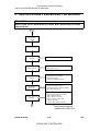
2.2 COPIER INSTALLATION PROCEDURE . . . . . . . . . . . . . . . . . . . . . . . . . . . . 3-7
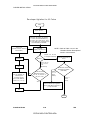
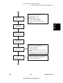
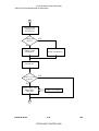
3. INSTALLATION PROCEDURE FLOWCHART . . . . . . . . . . . . . . 3-36
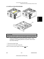
4. PAPER TRAY UNIT (A549/A550) INSTALLATION . . . . . . . . . . . 3-40
4.1 ACCESSORY CHECK. . . . . . . . . . . . . . . . . . . . . . . . . . . . . . . . . . . . . . . . . . 3-40
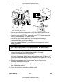
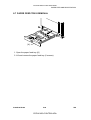
4.2 INSTALLATION PROCEDURE . . . . . . . . . . . . . . . . . . . . . . . . . . . . . . . . . . . 3-41
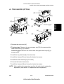
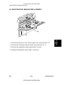
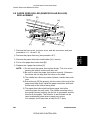
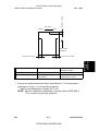
4.3 TRAY HEATER (OPTION) . . . . . . . . . . . . . . . . . . . . . . . . . . . . . . . . . . . . . . 3-43
5. ARDF (A548) INSTALLATION . . . . . . . . . . . . . . . . . . . . . . . . . . . 3-44
5.1 ACCESSORY CHECK. . . . . . . . . . . . . . . . . . . . . . . . . . . . . . . . . . . . . . . . . . 3-44
5.2 INSTALLATION PROCEDURE . . . . . . . . . . . . . . . . . . . . . . . . . . . . . . . . . . . 3-45
6. 10-BIN SORTER (A555) INSTALLATION . . . . . . . . . . . . . . . . . . 3-46
6.1 ACCESSORY CHECK. . . . . . . . . . . . . . . . . . . . . . . . . . . . . . . . . . . . . . . . . . 3-46
6.2 INSTALLATION PROCEDURE . . . . . . . . . . . . . . . . . . . . . . . . . . . . . . . . . . 3-47
7. FILM PROJECTOR TABLE (A579) INSTALLATION. . . . . . . . . . 3-51
8. FILM PROJECTOR UNIT (A718) INSTALLATION . . . . . . . . . . . 3-53
8.1 ACCESSORY CHECK. . . . . . . . . . . . . . . . . . . . . . . . . . . . . . . . . . . . . . . . . . 3-53
SM
vii
CÓPIA NÃO CONTROLADA
A166/A187/A189
CÓPIA NÃO CONTROLADA
8.2 INSTALLATION PROCEDURE . . . . . . . . . . . . . . . . . . . . . . . . . . . . . . . . . . . 3-54
9. OTHERS . . . . . . . . . . . . . . . . . . . . . . . . . . . . . . . . . . . . . . . . . . . . 3-61
9.1 KEY COUNTER. . . . . . . . . . . . . . . . . . . . . . . . . . . . . . . . . . . . . . . . . . . . . . . 3-61
9.1.1 Key Counter Installation . . . . . . . . . . . . . . . . . . . . . . . . . . . . . . . . . . . . . 3-61
9.1.2 Setting up the SP Modes for the Key Counter . . . . . . . . . . . . . . . . . . . . 3-62
9.2 MOUNTING THE PACKING RETAINERS FOR MOVING THE COPIER . . 3-63
SERVICE TABLES
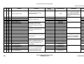
1. SERVICE PROGRAM MODES . . . . . . . . . . . . . . . . . . . . . . . . . . . . 4-1
1.1 SP TABLE . . . . . . . . . . . . . . . . . . . . . . . . . . . . . . . . . . . . . . . . . . . . . . . . . . . . 4-1
1.2 SERVICE PROGRAM MODE OPERATION . . . . . . . . . . . . . . . . . . . . . . . . . . 4-1
1.2.1 LCD Display . . . . . . . . . . . . . . . . . . . . . . . . . . . . . . . . . . . . . . . . . . . . . . . 4-1
1.3 SP MODE ADDITIONAL NOTES . . . . . . . . . . . . . . . . . . . . . . . . . . . . . . . . . . 4-2
1.3.1 SP 3-973 Process Control Interval Self Check . . . . . . . . . . . . . . . . . . . . 4-2
1.3.2 SP4-301 APS Data Confirmation. . . . . . . . . . . . . . . . . . . . . . . . . . . . . . . 4-2
1.3.3 SP5-501 PM Counter . . . . . . . . . . . . . . . . . . . . . . . . . . . . . . . . . . . . . . . . 4-2
1.3.4 SP5-802-1 Printer Free Run . . . . . . . . . . . . . . . . . . . . . . . . . . . . . . . . . . 4-2
1.3.5 SP5-802-4 System Free Run. . . . . . . . . . . . . . . . . . . . . . . . . . . . . . . . . . 4-4
1.3.6 SP5-803 Input Check . . . . . . . . . . . . . . . . . . . . . . . . . . . . . . . . . . . . . . . . 4-4
1.3.7 SP5-804 Output Check . . . . . . . . . . . . . . . . . . . . . . . . . . . . . . . . . . . . . . 4-7
1.3.8 SP5-955 Printer Test Pattern . . . . . . . . . . . . . . . . . . . . . . . . . . . . . . . . . . 4-9
1.3.9 SP5-974 Auto Memory Call . . . . . . . . . . . . . . . . . . . . . . . . . . . . . . . . . . . 4-9
1.3.10 SP6-102 Sort/Stack Limitation . . . . . . . . . . . . . . . . . . . . . . . . . . . . . . . . 4-9
1.3.11 SP6-107 Sorter Free Run . . . . . . . . . . . . . . . . . . . . . . . . . . . . . . . . . . 4-10
1.3.12 SP6-901 Optional Paper Bank Input Check. . . . . . . . . . . . . . . . . . . . . 4-10
1.3.13 SP6-902 Output Check for the Optional Paper Bank Unit . . . . . . . . . . 4-12
1.3.14 SP6-903 Sorter Input Check . . . . . . . . . . . . . . . . . . . . . . . . . . . . . . . . 4-13
1.3.15 SP6-904 Sorter Output Check . . . . . . . . . . . . . . . . . . . . . . . . . . . . . . 4-13
1.3.16 SP7-507-1 Paper Jam (Last 10) . . . . . . . . . . . . . . . . . . . . . . . . . . . . . 4-14
1.3.17 SP7-507-2 Original Jam (Last 10) . . . . . . . . . . . . . . . . . . . . . . . . . . . . 4-16
2. USER PROGRAM MODES . . . . . . . . . . . . . . . . . . . . . . . . . . . . . . 4-17
A166/A187/A189
viii
CÓPIA NÃO CONTROLADA
SM
CÓPIA NÃO CONTROLADA
2.1 USER PROGRAM MODE OPERATION . . . . . . . . . . . . . . . . . . . . . . . . . . . . 4-17
2.2 UP MODE TABLE . . . . . . . . . . . . . . . . . . . . . . . . . . . . . . . . . . . . . . . . . . . . . 4-18
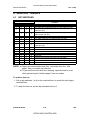
3. TP/FUSE/LED/SW . . . . . . . . . . . . . . . . . . . . . . . . . . . . . . . . . . . . . 4-30
3.1 TEST POINT . . . . . . . . . . . . . . . . . . . . . . . . . . . . . . . . . . . . . . . . . . . . . . . . . 4-30
3.2 FUSE CONDITIONS . . . . . . . . . . . . . . . . . . . . . . . . . . . . . . . . . . . . . . . . . . . 4-34
3.3 LED CONDITIONS . . . . . . . . . . . . . . . . . . . . . . . . . . . . . . . . . . . . . . . . . . . . 4-34
3.4 SWITCHES . . . . . . . . . . . . . . . . . . . . . . . . . . . . . . . . . . . . . . . . . . . . . . . . . . 4-35
4. REGULAR PM TABLE . . . . . . . . . . . . . . . . . . . . . . . . . . . . . . . . . 4-36
5. SP MODES USED AFTER REPLACEMENT
AND CLEANING . . . . . . . . . . . . . . . . . . . . . . . . . . . . . . . . . . . . . . 4-43
6. REGULAR PM PROCEDURE . . . . . . . . . . . . . . . . . . . . . . . . . . . . 4-45
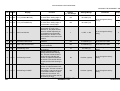
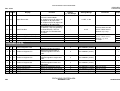
REPLACEMENT AND ADJUSTMENT
1. EXTERIOR . . . . . . . . . . . . . . . . . . . . . . . . . . . . . . . . . . . . . . . . . . . . 5-1
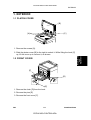
1.1 PLATEN COVER . . . . . . . . . . . . . . . . . . . . . . . . . . . . . . . . . . . . . . . . . . . . . . 5-1
1.2 FRONT COVER . . . . . . . . . . . . . . . . . . . . . . . . . . . . . . . . . . . . . . . . . . . . . . . 5-1
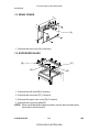
1.3 REAR COVER . . . . . . . . . . . . . . . . . . . . . . . . . . . . . . . . . . . . . . . . . . . . . . . . 5-2
1.4 EXPOSURE GLASS . . . . . . . . . . . . . . . . . . . . . . . . . . . . . . . . . . . . . . . . . . . . 5-2
1.5 UPPER COVERS . . . . . . . . . . . . . . . . . . . . . . . . . . . . . . . . . . . . . . . . . . . . . . 5-3
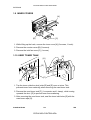
1.6 OPERATION PANEL. . . . . . . . . . . . . . . . . . . . . . . . . . . . . . . . . . . . . . . . . . . . 5-4
1.6.1 A166/A187 Copiers . . . . . . . . . . . . . . . . . . . . . . . . . . . . . . . . . . . . . . . . . 5-4
1.6.2 A189 Copier . . . . . . . . . . . . . . . . . . . . . . . . . . . . . . . . . . . . . . . . . . . . . . 5-4
1.7 RIGHT COVERS . . . . . . . . . . . . . . . . . . . . . . . . . . . . . . . . . . . . . . . . . . . . . . 5-5
1.8 LEFT COVERS . . . . . . . . . . . . . . . . . . . . . . . . . . . . . . . . . . . . . . . . . . . . . . . . 5-5
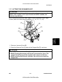
1.9 INNER COVERS . . . . . . . . . . . . . . . . . . . . . . . . . . . . . . . . . . . . . . . . . . . . . . 5-6
1.10 USED TONER TANK . . . . . . . . . . . . . . . . . . . . . . . . . . . . . . . . . . . . . . . . . . 5-6
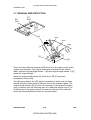
1.11 LIFTING THE SCANNER UNIT. . . . . . . . . . . . . . . . . . . . . . . . . . . . . . . . . . . 5-7
2. DRUM UNIT . . . . . . . . . . . . . . . . . . . . . . . . . . . . . . . . . . . . . . . . . . 5-8
2.1 DRUM REPLACEMENT . . . . . . . . . . . . . . . . . . . . . . . . . . . . . . . . . . . . . . . . . 5-8
2.2 CLEANING BLADE REPLACEMENT . . . . . . . . . . . . . . . . . . . . . . . . . . . . . 5-10
2.3 CLEANING BRUSH REPLACEMENT . . . . . . . . . . . . . . . . . . . . . . . . . . . . . 5-11
SM
ix
CÓPIA NÃO CONTROLADA
A166/A187/A189
CÓPIA NÃO CONTROLADA
2.4 LUBRICANT BAR REPLACEMENT . . . . . . . . . . . . . . . . . . . . . . . . . . . . . . 5-12
2.5 CHARGE GRID AND CORONA WIRE REPLACEMENT . . . . . . . . . . . . . . 5-13
3. SCANNER UNIT . . . . . . . . . . . . . . . . . . . . . . . . . . . . . . . . . . . . . . 5-14
3.1 SCANNER UNIT REMOVAL . . . . . . . . . . . . . . . . . . . . . . . . . . . . . . . . . . . . . 5-14
3.2 HALOGEN LAMP REPLACEMENT . . . . . . . . . . . . . . . . . . . . . . . . . . . . . . . 5-15
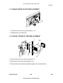
3.3 SCANNER INNER COVER REMOVAL
. . . . . . . . . . . . . . . . . . . . . . . . . . . 5-16
3.4 SBU REPLACEMENT . . . . . . . . . . . . . . . . . . . . . . . . . . . . . . . . . . . . . . . . . . 5-16
3.5 SCANNER IPU BOARD REPLACEMENT . . . . . . . . . . . . . . . . . . . . . . . . . . 5-17
3.6 SCANNER HOME POSITION SENSOR REPLACEMENT . . . . . . . . . . . . . 5-18
3.7 SCANNER WIRE REPLACEMENT . . . . . . . . . . . . . . . . . . . . . . . . . . . . . . . 5-19
3.8 IDU (IMAGE DISCRIMINATE UNIT) REPLACEMENT . . . . . . . . . . . . . . . . 5-23
4. COPY IMAGE ADJUSTMENT. . . . . . . . . . . . . . . . . . . . . . . . . . . . 5-24
4.1 PRINTER γ ADJUSTMENT . . . . . . . . . . . . . . . . . . . . . . . . . . . . . . . . . . . . . . 5-24
4.1.1 Auto Color Calibration (ACC) . . . . . . . . . . . . . . . . . . . . . . . . . . . . . . . . 5-24
4.1.2 BkCMY Color Balance Adjustment . . . . . . . . . . . . . . . . . . . . . . . . . . . . 5-25
4.2 MAIN SCAN POSITION DOT CORRECTION. . . . . . . . . . . . . . . . . . . . . . . . 5-28
5. LASER UNIT . . . . . . . . . . . . . . . . . . . . . . . . . . . . . . . . . . . . . . . . . 5-31
5.1 POLYGON MOTOR REPLACEMENT . . . . . . . . . . . . . . . . . . . . . . . . . . . . . 5-32
5.2 LASER SYNCHRONIZING DETECTOR BOARD REPLACEMENT . . . . . . . 5-34
5.3 LD UNIT REPLACEMENT . . . . . . . . . . . . . . . . . . . . . . . . . . . . . . . . . . . . . . 5-35
6. DEVELOPMENT UNIT. . . . . . . . . . . . . . . . . . . . . . . . . . . . . . . . . . 5-36
6.1 DEVELOPER. . . . . . . . . . . . . . . . . . . . . . . . . . . . . . . . . . . . . . . . . . . . . . . . . 5-36
6.1.1 Developer Collection . . . . . . . . . . . . . . . . . . . . . . . . . . . . . . . . . . . . . . 5-36
6.2 PROCESS CONTROL SELF-CHECK. . . . . . . . . . . . . . . . . . . . . . . . . . . . . . 5-48
6.3 REVOLVER MOTOR REPLACEMENT . . . . . . . . . . . . . . . . . . . . . . . . . . . . 5-49
6.4 DEVELOPMENT MOTOR REPLACEMENT . . . . . . . . . . . . . . . . . . . . . . . . 5-50
7. TRANSFER BELT UNIT . . . . . . . . . . . . . . . . . . . . . . . . . . . . . . . 5-51
7.1 TRANSFER BELT SECTION . . . . . . . . . . . . . . . . . . . . . . . . . . . . . . . . . . . . 5-51
7.1.1 Transfer Belt . . . . . . . . . . . . . . . . . . . . . . . . . . . . . . . . . . . . . . . . . . . . . 5-51
7.2 CLEANING UNIT . . . . . . . . . . . . . . . . . . . . . . . . . . . . . . . . . . . . . . . . . . . . . . 5-53
7.2.1 Cleaning Blade Replacement . . . . . . . . . . . . . . . . . . . . . . . . . . . . . . . . 5-53
A166/A187/A189
x
CÓPIA NÃO CONTROLADA
SM
CÓPIA NÃO CONTROLADA
7.2.2 Belt Cleaning Solenoid Replacement . . . . . . . . . . . . . . . . . . . . . . . . . . 5-54
7.2.3 Entrance Seal Replacement . . . . . . . . . . . . . . . . . . . . . . . . . . . . . . . . . 5-55
7.3 BELT TRANSFER CORONA WIRE . . . . . . . . . . . . . . . . . . . . . . . . . . . . . . . 5-56
7.4 LUBRICANT UNIT . . . . . . . . . . . . . . . . . . . . . . . . . . . . . . . . . . . . . . . . . . . . . 5-57
7.4.1 Lubricant Brush and Bar Replacement
. . . . . . . . . . . . . . . . . . . . . . . . 5-57
7.4.2 Lubricant Solenoid Replacement . . . . . . . . . . . . . . . . . . . . . . . . . . . . . 5-58
7.5 PAPER TRANSFER CORONA WIRE . . . . . . . . . . . . . . . . . . . . . . . . . . . . . 5-59
8. PAPER FEED AND REGISTRATION . . . . . . . . . . . . . . . . . . . . . . 5-60
8.1 BY-PASS FEED TABLE REMOVAL . . . . . . . . . . . . . . . . . . . . . . . . . . . . . . 5-60
8.2 BY-PASS FEED ROLLER, PICK-UP ROLLER, AND SEPARATION
ROLLER REPLACEMENT . . . . . . . . . . . . . . . . . . . . . . . . . . . . . . . . . . . . . . 5-61
8.3 BY-PASS FEED UNIT REPLACEMENT . . . . . . . . . . . . . . . . . . . . . . . . . . . 5-62
8.4 BY-PASS FEED PICK-UP SOLENOIDS AND END
SENSOR REPLACEMENT . . . . . . . . . . . . . . . . . . . . . . . . . . . . . . . . . . . . . 5-63
8.5 BY-PASS FEED PAPER SIZE SENSOR REPLACEMENT . . . . . . . . . . . . . 5-64
8.6 REGISTRATION SENSOR REPLACEMENT . . . . . . . . . . . . . . . . . . . . . . . 5-65
8.7 PAPER FEED TRAY REMOVAL . . . . . . . . . . . . . . . . . . . . . . . . . . . . . . . . . 5-66
8.8 PAPER FEED ROLLER (SEMICIRCULAR ROLLER) REPLACEMENT . . . 5-67
8.9 PAPER FEED CLUTCH REPLACEMENT . . . . . . . . . . . . . . . . . . . . . . . . . . 5-68
8.10 VERTICAL TRANSPORT SWITCH AND SENSOR
REPLACEMENT . . . . . . . . . . . . . . . . . . . . . . . . . . . . . . . . . . . . . . . . . . . . 5-69
8.11 COPY IMAGE AREA ADJUSTMENT . . . . . . . . . . . . . . . . . . . . . . . . . . . . . 5-70
9. PAPER TRANSPORT AND FUSING . . . . . . . . . . . . . . . . . . . . . . 5-72
9.1 TRANSPORT UNIT REMOVAL. . . . . . . . . . . . . . . . . . . . . . . . . . . . . . . . . . . 5-72
9.2 TRANSPORT BELT REMOVAL . . . . . . . . . . . . . . . . . . . . . . . . . . . . . . . . . . 5-73
9.3 FUSING UNIT REMOVAL . . . . . . . . . . . . . . . . . . . . . . . . . . . . . . . . . . . . . . 5-74
9.4 OIL SUPPLY PAD REPLACEMENT . . . . . . . . . . . . . . . . . . . . . . . . . . . . . . 5-75
9.5 HOT ROLLER, PRESSURE ROLLER, AND FUSING
LAMP REPLACEMENT . . . . . . . . . . . . . . . . . . . . . . . . . . . . . . . . . . . . . . . . 5-76
9.6 HOT ROLLER THERMISTOR REPLACEMENT . . . . . . . . . . . . . . . . . . . . . 5-81
9.7 HOT ROLLER THERMOFUSE REPLACEMENT . . . . . . . . . . . . . . . . . . . . . 5-81
9.8 PRESSURE ROLLER THERMISTOR REPLACEMENT . . . . . . . . . . . . . . . 5-82
9.9 PRESSURE ROLLER THERMOFUSE REPLACEMENT . . . . . . . . . . . . . . 5-82
9.10 CLEANING ROLLER OIL PAN AND SCRAPER . . . . . . . . . . . . . . . . . . . . 5-83
SM
xi
CÓPIA NÃO CONTROLADA
A166/A187/A189
CÓPIA NÃO CONTROLADA
9.11 OIL PAN PADS . . . . . . . . . . . . . . . . . . . . . . . . . . . . . . . . . . . . . . . . . . . . . 5-84
9.12 FUSING ENTRANCE GUIDE ADJUSTMENT . . . . . . . . . . . . . . . . . . . . . . 5-85
9.13 NIP BAND WIDTH ADJUSTMENT . . . . . . . . . . . . . . . . . . . . . . . . . . . . . . 5-86
9.13.1 Procedure . . . . . . . . . . . . . . . . . . . . . . . . . . . . . . . . . . . . . . . . . . . . . . 5-86
9.13.2 Troubleshooting . . . . . . . . . . . . . . . . . . . . . . . . . . . . . . . . . . . . . . . . . . 5-87
10. DUPLEX UNIT . . . . . . . . . . . . . . . . . . . . . . . . . . . . . . . . . . . . . . 5-88
10.1 DUPLEX UNIT REMOVAL . . . . . . . . . . . . . . . . . . . . . . . . . . . . . . . . . . . . . 5-88
10.2 SEPARATION ROLLER REPLACEMENT . . . . . . . . . . . . . . . . . . . . . . . . . 5-88
10.3 FEED ROLLER REPLACEMENT . . . . . . . . . . . . . . . . . . . . . . . . . . . . . . . 5-89
10.4 DUPLEX FEED MOTOR REPLACEMENT . . . . . . . . . . . . . . . . . . . . . . . . 5-90
11. FILTERS . . . . . . . . . . . . . . . . . . . . . . . . . . . . . . . . . . . . . . . . . . . 5-92
11.1 OPTICS FAN FILTER REPLACEMENT . . . . . . . . . . . . . . . . . . . . . . . . . . . 5-92
11.2 EXHAUST OZONE FILTER REPLACEMENT . . . . . . . . . . . . . . . . . . . . . . 5-92
11.3 FUSING FILTER REPLACEMENT . . . . . . . . . . . . . . . . . . . . . . . . . . . . . . . 5-93
11.4 CHARGE INLET FILTER REPLACEMENT . . . . . . . . . . . . . . . . . . . . . . . . 5-93
11.5 REAR OZONE FILTER REPLACEMENT . . . . . . . . . . . . . . . . . . . . . . . . . . 5-94
11.6 FRONT OZONE FILTER REPLACEMENT . . . . . . . . . . . . . . . . . . . . . . . . 5-94
11.7 PAPER IT OZONE FILTER REPLACEMENT . . . . . . . . . . . . . . . . . . . . . . 5-95
11.8 POWER SUPPLY OZONE FILTER REPLACEMENT . . . . . . . . . . . . . . . . 5-95
12. OTHERS . . . . . . . . . . . . . . . . . . . . . . . . . . . . . . . . . . . . . . . . . . . 5-96
12.1 SCU . . . . . . . . . . . . . . . . . . . . . . . . . . . . . . . . . . . . . . . . . . . . . . . . . . . . . . . 5-96
12.1.1 SCU Replacement . . . . . . . . . . . . . . . . . . . . . . . . . . . . . . . . . . . . . . . . 5-96
12.2 RAM CLEAR . . . . . . . . . . . . . . . . . . . . . . . . . . . . . . . . . . . . . . . . . . . . . . . . 5-98
12.2.1 RAM (Memory Board) Clear Procedure . . . . . . . . . . . . . . . . . . . . . . . . 5-98
12.3 MAIN COUNTER . . . . . . . . . . . . . . . . . . . . . . . . . . . . . . . . . . . . . . . . . . . . . 5-98
12.3.1 Main Counter Replacement . . . . . . . . . . . . . . . . . . . . . . . . . . . . . . . . . 5-98
12.4 TOUCH PANEL CALIBRATION . . . . . . . . . . . . . . . . . . . . . . . . . . . . . . . . 5-101
TROUBLESHOOTING
1. SERVICE CALL CONDITIONS . . . . . . . . . . . . . . . . . . . . . . . . . . . . 6-1
2. HOW TO DETERMINE IF THE POTENTIAL
SENSOR OR ID SENSOR IS DEFECTIVE. . . . . . . . . . . . . . . . . . 6-34
A166/A187/A189
xii
CÓPIA NÃO CONTROLADA
SM
CÓPIA NÃO CONTROLADA
3. TROUBLESHOOTING FOR COUNTERS. . . . . . . . . . . . . . . . . . . 6-37
AUTO REVERSE DOCUMENT FEEDER A548
1. SPECIFICATIONS . . . . . . . . . . . . . . . . . . . . . . . . . . . . . . . . . . . . . . 7-1
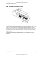
2. COMPONENT LAYOUT . . . . . . . . . . . . . . . . . . . . . . . . . . . . . . . . . 7-2
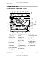
2.1 MECHANICAL COMPONENTS . . . . . . . . . . . . . . . . . . . . . . . . . . . . . . . . . . . 7-2
2.2 ELECTRICAL COMPONENTS . . . . . . . . . . . . . . . . . . . . . . . . . . . . . . . . . . . . 7-3
3. ELECTRICAL COMPONENT DESCRIPTION . . . . . . . . . . . . . . . . 7-4
4. DETAILED DESCRIPTIONS . . . . . . . . . . . . . . . . . . . . . . . . . . . . . . 7-5
4.1 ORIGINAL PICK-UP MECHANISM . . . . . . . . . . . . . . . . . . . . . . . . . . . . . . . . . 7-5
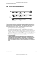
4.2 SEPARATION AND PAPER FEED MECHANISM . . . . . . . . . . . . . . . . . . . . . 7-6
4.3 FRICTION BELT DRIVE MECHANISM. . . . . . . . . . . . . . . . . . . . . . . . . . . . . . 7-7
4.4 ORIGINAL SIZE DETECTION. . . . . . . . . . . . . . . . . . . . . . . . . . . . . . . . . . . . . 7-8
4.5 PAPER TRANSPORT MECHANISM . . . . . . . . . . . . . . . . . . . . . . . . . . . . . . . 7-9
4.6 THICK/THIN ORIGINAL MODES . . . . . . . . . . . . . . . . . . . . . . . . . . . . . . . . . 7-10
4.7 ORIGINAL FEED-OUT MECHANISM . . . . . . . . . . . . . . . . . . . . . . . . . . . . . . 7-11
4.8 TWO-SIDED ORIGINAL FEED MECHANISM . . . . . . . . . . . . . . . . . . . . . . . 7-12
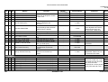
5. TIMING CHARTS. . . . . . . . . . . . . . . . . . . . . . . . . . . . . . . . . . . . . . 7-13
5.1 A4 SIDEWAYS: 1 SIDED ORIGINAL . . . . . . . . . . . . . . . . . . . . . . . . . . . . . . 7-13
5.2 COMBINE 2 ORIGINAL MODE . . . . . . . . . . . . . . . . . . . . . . . . . . . . . . . . . . . 7-14
5.3 A4 SIDEWAYS: DUPLEX . . . . . . . . . . . . . . . . . . . . . . . . . . . . . . . . . . . . . . . 7-15
6. SERVICE TABLES . . . . . . . . . . . . . . . . . . . . . . . . . . . . . . . . . . . . 7-16
6.1 DIP SWITCHES. . . . . . . . . . . . . . . . . . . . . . . . . . . . . . . . . . . . . . . . . . . . . . . 7-16
6.2 VARIABLE RESISTORS . . . . . . . . . . . . . . . . . . . . . . . . . . . . . . . . . . . . . . . . 7-17
6.3 LED . . . . . . . . . . . . . . . . . . . . . . . . . . . . . . . . . . . . . . . . . . . . . . . . . . . . . . . . 7-17
6.4 FUSE . . . . . . . . . . . . . . . . . . . . . . . . . . . . . . . . . . . . . . . . . . . . . . . . . . . . . . . 7-17
7. REPLACEMENT AND ADJUSTMENT . . . . . . . . . . . . . . . . . . . . . 7-18
7.1 TRANSPORT BELT REPLACEMENT. . . . . . . . . . . . . . . . . . . . . . . . . . . . . . 7-18
7.2 FEED ROLLER REPLACEMENT . . . . . . . . . . . . . . . . . . . . . . . . . . . . . . . . . 7-19
7.3 FRICTION BELT REPLACEMENT . . . . . . . . . . . . . . . . . . . . . . . . . . . . . . . . 7-20
7.4 ORIGINAL SET AND ORIGINAL WIDTH SENSOR REPLACEMENT . . . . . 7-21
SM
xiii
CÓPIA NÃO CONTROLADA
A166/A187/A189
CÓPIA NÃO CONTROLADA
7.5 VERTICAL REGISTRATION ADJUSTMENT . . . . . . . . . . . . . . . . . . . . . . . . 7-22
7.5.1 One Sided Thin Original Mode. . . . . . . . . . . . . . . . . . . . . . . . . . . . . . . . 7-22
7.5.2 Two Sided Original Mode . . . . . . . . . . . . . . . . . . . . . . . . . . . . . . . . . . . 7-23
7.6 SIDE-TO-SIDE REGISTRATION (DF POSITIONING) ADJUSTMENT . . . . 7-24
PAPER TRAY UNIT A549/A550
1. SPECIFICATIONS . . . . . . . . . . . . . . . . . . . . . . . . . . . . . . . . . . . . . . 8-1
2. COMPONENT LAYOUT . . . . . . . . . . . . . . . . . . . . . . . . . . . . . . . . . 8-2
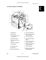
2.1 MECHANICAL COMPONENT LAYOUT . . . . . . . . . . . . . . . . . . . . . . . . . . . . . 8-2
2.2 DRIVE LAYOUT . . . . . . . . . . . . . . . . . . . . . . . . . . . . . . . . . . . . . . . . . . . . . . . 8-3
2.3 ELECTRICAL COMPONENT DESCRIPTION. . . . . . . . . . . . . . . . . . . . . . . . . 8-4
3. OVERVIEW . . . . . . . . . . . . . . . . . . . . . . . . . . . . . . . . . . . . . . . . . . . 8-5
4. DRIVE MECHANISM . . . . . . . . . . . . . . . . . . . . . . . . . . . . . . . . . . . . 8-6
5. PAPER FEED AND MISFEED DETECTION TIMING. . . . . . . . . . . 8-7
6. SERVICE TABLES . . . . . . . . . . . . . . . . . . . . . . . . . . . . . . . . . . . . . 8-8
6.1 DIP SWITCHES. . . . . . . . . . . . . . . . . . . . . . . . . . . . . . . . . . . . . . . . . . . . . . . . 8-8
6.2 TEST POINTS . . . . . . . . . . . . . . . . . . . . . . . . . . . . . . . . . . . . . . . . . . . . . . . . . 8-9
7. REPLACEMENT AND ADJUSTMENT . . . . . . . . . . . . . . . . . . . . . 8-10
7.1 EXTERIOR COVER REMOVAL . . . . . . . . . . . . . . . . . . . . . . . . . . . . . . . . . . 8-10
7.2 PAPER FEED CLUTCH REPLACEMENT . . . . . . . . . . . . . . . . . . . . . . . . . . 8-11
7.3 PAPER FEED UNIT REPLACEMENT. . . . . . . . . . . . . . . . . . . . . . . . . . . . . . 8-12
7.4 FEED ROLLER, PICK-UP ROLLER, AND REVERSE
ROLLER REPLACEMENT . . . . . . . . . . . . . . . . . . . . . . . . . . . . . . . . . . . . . . 8-13
7.5 RELAY SENSOR REPLACEMENT. . . . . . . . . . . . . . . . . . . . . . . . . . . . . . . . 8-14
10-BIN SORTER STAPLER A555
1. SPECIFICATIONS . . . . . . . . . . . . . . . . . . . . . . . . . . . . . . . . . . . . . . 9-1
2. COMPONENT LAYOUT . . . . . . . . . . . . . . . . . . . . . . . . . . . . . . . . . 9-3
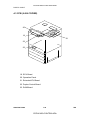
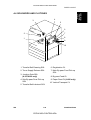
2.1 MECHANICAL COMPONENT LAYOUT . . . . . . . . . . . . . . . . . . . . . . . . . . . . . 9-3
2.2 DRIVE LAYOUT . . . . . . . . . . . . . . . . . . . . . . . . . . . . . . . . . . . . . . . . . . . . . . . 9-4
2.3 ELECTRICAL COMPONENT DESCRIPTION. . . . . . . . . . . . . . . . . . . . . . . . . 9-5
A166/A187/A189
xiv
CÓPIA NÃO CONTROLADA
SM
CÓPIA NÃO CONTROLADA
3. BASIC OPERATION . . . . . . . . . . . . . . . . . . . . . . . . . . . . . . . . . . . . 9-6
3.1 NORMAL MODE AND SORT/STACK MODE . . . . . . . . . . . . . . . . . . . . . . . . . 9-6
3.2 STAPLE MODE . . . . . . . . . . . . . . . . . . . . . . . . . . . . . . . . . . . . . . . . . . . . . . . . 9-8
3.3 BIN DRIVE MECHANISM . . . . . . . . . . . . . . . . . . . . . . . . . . . . . . . . . . . . . . . 9-10
3.4 BIN HOME POSITION. . . . . . . . . . . . . . . . . . . . . . . . . . . . . . . . . . . . . . . . . . 9-11
3.5 JOGGER MECHANISM. . . . . . . . . . . . . . . . . . . . . . . . . . . . . . . . . . . . . . . . . 9-12
3.6 GRIP ASSEMBLY . . . . . . . . . . . . . . . . . . . . . . . . . . . . . . . . . . . . . . . . . . . . . 9-13
3.7 STAPLER UNIT . . . . . . . . . . . . . . . . . . . . . . . . . . . . . . . . . . . . . . . . . . . . . . . 9-14
3.8 STAPLER SWITCH . . . . . . . . . . . . . . . . . . . . . . . . . . . . . . . . . . . . . . . . . . . . 9-15
3.9 PAPER FEED AND MISFEED DETECTION TIMING . . . . . . . . . . . . . . . . . . 9-16
3.10 JAM DETECTION . . . . . . . . . . . . . . . . . . . . . . . . . . . . . . . . . . . . . . . . . . . . 9-18
4. SERVICE TABLES . . . . . . . . . . . . . . . . . . . . . . . . . . . . . . . . . . . . 9-19
4.1 DIP SWITCHES. . . . . . . . . . . . . . . . . . . . . . . . . . . . . . . . . . . . . . . . . . . . . . . 9-19
4.2 TEST POINTS . . . . . . . . . . . . . . . . . . . . . . . . . . . . . . . . . . . . . . . . . . . . . . . . 9-20
4.3 LED . . . . . . . . . . . . . . . . . . . . . . . . . . . . . . . . . . . . . . . . . . . . . . . . . . . . . . . . 9-20
4.4 VARIABLE RESISTOR . . . . . . . . . . . . . . . . . . . . . . . . . . . . . . . . . . . . . . . . . 9-20
5. REPLACEMENT AND ADJUSTMENT . . . . . . . . . . . . . . . . . . . . . 9-21
5.1 EXTERIOR COVER REMOVAL . . . . . . . . . . . . . . . . . . . . . . . . . . . . . . . . . . 9-21
5.2 STAPLE UNIT REMOVAL . . . . . . . . . . . . . . . . . . . . . . . . . . . . . . . . . . . . . . . 9-21
5.3 GRIP ARM REPLACEMENT . . . . . . . . . . . . . . . . . . . . . . . . . . . . . . . . . . . . . 9-22
5.4 BIN REPLACEMENT. . . . . . . . . . . . . . . . . . . . . . . . . . . . . . . . . . . . . . . . . . . 9-23
5.5 TRANSPORT MOTOR REPLACEMENT . . . . . . . . . . . . . . . . . . . . . . . . . . . 9-24
5.6 BIN JAM SENSOR ADJUSTMENT . . . . . . . . . . . . . . . . . . . . . . . . . . . . . . . . 9-25
FILM PROJECTOR UNIT A718
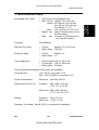
1. SPECIFICATIONS . . . . . . . . . . . . . . . . . . . . . . . . . . . . . . . . . . . . . 10-1
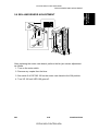
2. ELECTRICAL COMPONENT LAYOUT AND DESCRIPTIONS . . 10-2
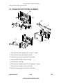
3. SECTIONAL DESCRIPTIONS . . . . . . . . . . . . . . . . . . . . . . . . . . . 10-3
3.1 OVERVIEW . . . . . . . . . . . . . . . . . . . . . . . . . . . . . . . . . . . . . . . . . . . . . . . . . . 10-3
3.2 SHADING . . . . . . . . . . . . . . . . . . . . . . . . . . . . . . . . . . . . . . . . . . . . . . . . . . . 10-4
3.3 MIRROR UNIT . . . . . . . . . . . . . . . . . . . . . . . . . . . . . . . . . . . . . . . . . . . . . . . . 10-5
SM
xv
CÓPIA NÃO CONTROLADA
A166/A187/A189
CÓPIA NÃO CONTROLADA
APPENDIX
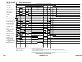
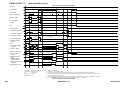
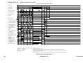
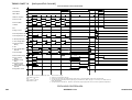
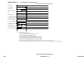
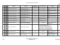
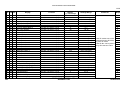
1. TIMING CHART
Timing Chart 1 Normal speed/Bk/A4 . . . . . . . . . . . . . . . . . . . . . . . . . . . . . . . . . . 11-1
Timing Chart 2 Normal speed/Bk/A3 . . . . . . . . . . . . . . . . . . . . . . . . . . . . . . . . . . 11-2
Timing Chart 3 Normal speed/Red/A4 . . . . . . . . . . . . . . . . . . . . . . . . . . . . . . . . . 11-3
Timing Chart 4 Normal speed/Red/A3 . . . . . . . . . . . . . . . . . . . . . . . . . . . . . . . . . 11-4
Timing Chart 5 Normal speed/Green/A4. . . . . . . . . . . . . . . . . . . . . . . . . . . . . . . . 11-5
Timing Chart 6 Normal speed/Green/A3. . . . . . . . . . . . . . . . . . . . . . . . . . . . . . . . 11-6
Timing Chart 7 Normal speed/Full Color/A4 . . . . . . . . . . . . . . . . . . . . . . . . . . . . . 11-7
Timing Chart 8 Normal speed/Full Color/A3 . . . . . . . . . . . . . . . . . . . . . . . . . . . . . 11-8
Timing Chart 9 Half-speed/Bk/A4 . . . . . . . . . . . . . . . . . . . . . . . . . . . . . . . . . . . . . 11-9
Timing Chart 10 Half-speed/Bk/A3 . . . . . . . . . . . . . . . . . . . . . . . . . . . . . . . . . . . 11-10
Timing Chart 11 Half-speed/Red/A4 . . . . . . . . . . . . . . . . . . . . . . . . . . . . . . . . . . 11-11
Timing Chart 12 Half-speed/Red/A3 . . . . . . . . . . . . . . . . . . . . . . . . . . . . . . . . . . 11-12
Timing Chart 13 Half-speed/Green/A4 . . . . . . . . . . . . . . . . . . . . . . . . . . . . . . . . 11-13
Timing Chart 14 Half-speed/Green/’A3. . . . . . . . . . . . . . . . . . . . . . . . . . . . . . . . 11-14
Timing Chart 15 Half-speed/Full Color/A4 . . . . . . . . . . . . . . . . . . . . . . . . . . . . . 11-15
Timing Chart 16 Half-speed/Full Color/A3 . . . . . . . . . . . . . . . . . . . . . . . . . . . . . 11-16
Timing Chart 17 Cartridge check sequence . . . . . . . . . . . . . . . . . . . . . . . . . . . . 11-17
Timing Chart 18 Sequence for the Revolver H.P. Process. . . . . . . . . . . . . . . . . 11-18
Timing Chart 19 Sequence for Lubrication (Forced Belt Cleaning) . . . . . . . . . . 11-19
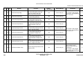
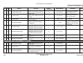
2. SP MODE TABLE. . . . . . . . . . . . . . . . . . . . . . . . . . . . . . . . . . . . . 11-20
BULLETINS
A166/A187/A189
xvi
CÓPIA NÃO CONTROLADA
SM
CÓPIA NÃO CONTROLADA
IMPORTANT SAFETY NOTICES
PREVENTION OF PHYSICAL INJURY
1. Before disassembling or assembling parts of the copier and peripherals,
make sure that the copier power cord is unplugged.
2. The wall outlet should be near the copier and easily accessible.
3. Note that some components of the copier and the paper tray unit are
supplied with electrical voltage even if the main switch is turned off.
4. If any adjustment or operation check has to be made with exterior covers
off or open while the main switch is turned on, keep hands away from
electrified or mechanically driven components.
5. If the start key is pressed before the copier completes the warm-up period
(Start key starts blinking red and green alternatively), keep hands away
from the mechanical and the electrical components as the copier starts
making copies as soon as the warm-up period is completed.
6. The inside and the metal parts of the fusing unit become extremely hot
while the copier is operating. Be careful to avoid touching those
components with your bare hands.
HEALTH SAFETY CONDITIONS
1. Never operate the copier without the ozone filters installed.
2. Always replace the ozone filters with the specified ones at the specified
intervals.
3. Toner and developer are non-toxic, but if you get either of them in your
eyes by accident, it may cause temporary eye discomfort. Try to remove
with eye drops or flush with water as first aid. If unsuccessful, get medical
attention.
OBSERVANCE OF ELECTRICAL SAFETY STANDARDS
1. The copier and its peripherals must be installed and maintained by a
customer service representative who has completed the training course
on those models.
CAUTION
2. The RAM board on the system control board has a lithium battery
which can explode if replaced incorrectly. Replace the battery only
with an identical one. The manufacturer recommends replacing the
entire RAM board. Do not recharge or burn this battery. Used
batteries must be handled in accordance with local regulations.
SM
a
CÓPIA NÃO CONTROLADA
A166
CÓPIA NÃO CONTROLADA
SAFETY AND ECOLOGICAL NOTES FOR DISPOSAL
1. Do not incinerate the toner bottle or the used toner. Toner dust may ignite
suddenly when exposed to open flame.
2. Dispose of used toner, developer, and organic photoconductor according
to local regulations. (These are non-toxic supplies.)
3. Dispose of replaced parts in accordance with local regulations.
4. When keeping used lithium batteries in order to dispose of them later, do
not put more than 100 batteries per sealed box. Storing larger numbers or
not sealing them apart may lead to chemical reactions and heat build-up.
LASER SAFETY
The Center for Devices and Radiological Health (CDRH) prohibits the repair
of laser-based optical units in the field. The optical housing unit can only be
repaired in a factory or at a location with the requisite equipment. The laser
subsystem is replaceable in the field by a qualified Customer Engineer. The
laser chassis is not repairable in the field. Customer engineers are therefore
directed to return all chassis and laser subsystems to the factory or service
depot when replacement of the optical subsystem is required.
DANGER
Use of controls, or adjustment, or performance of procedures other
than those specified in this manual may result in hazardous radiation
exposure.
WARNING FOR LASER UNIT
DANGER: Turn off the main switch before attempting any of the
procedures in the Laser Unit section. Laser beams
can seriously damage your eyes.
CAUTION MARKING:
A166
b
CÓPIA NÃO CONTROLADA
SM
CÓPIA NÃO CONTROLADA
SERVICE TABLES
REPLACEMENT AND ADJUSTMENT
TAB
POSITION 2
TAB
POSITION 3
AUTO REVERSE DOCUMENT FEEDER A548
TAB
POSITION 7
PAPER TRAY UNIT A550/A549
TAB
POSITION 8
TROUBLESHOOTING
TAB
POSITION 4
INSTALLATION PROCEDURE
APPENDIX - TIMING CHARTS / SP TABLES
TAB
POSITION 5
DETAILED SECTION DESCRIPTIONS
FILM PROJECTOR UNIT A718
TAB
POSITION 6
OVERALL MACHINE INFORMATION
10-BIN SORTER STAPLER A555
TAB
POSITION 1
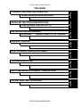
TAB INDEX
CÓPIA NÃO CONTROLADA
CÓPIA NÃO CONTROLADA
CÓPIA NÃO CONTROLADA
CÓPIA NÃO CONTROLADA
OVERALL
MACHINE INFORMATION
CÓPIA NÃO CONTROLADA
CÓPIA NÃO CONTROLADA
CÓPIA NÃO CONTROLADA
SPECIFICATIONS
1. SPECIFICATIONS
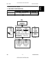
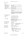
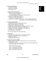
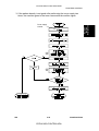
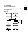
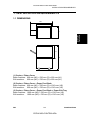
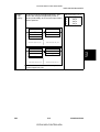
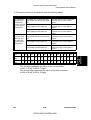
1.1 MACHINE CONFIGURATION
Aficio color (Basic Machine)
2003 (A166)
2103 (A187)
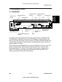
20-digit 2-line LCD
Operation Panel
Paper Tray Unit
250 Sheets
Edit Machine
2203 (A189)
144 mm x 192 mm
Touch Panel Display
Duplex
ARDF
(DF61)
(A548)
Copier
Sorter/Stapler
ST10
(A555)
Aficio Color
(A166/A187)
Aficio Color
(A189)
BASIC
EDIT
250-sheet Paper
Tray / Duplex Tray
Duplex Tray
FPU
SPU 3
(A718)
Type B
(A579)
FP Table
Paper Tray Unit
PS280
(A550)
PS290
(A549)
500 sheets
x 2 Trays
500 sheets
x 3 Trays
SM
1-1
CÓPIA NÃO CONTROLADA
A166/A187/A189
Overall
Machine
Information
CÓPIA NÃO CONTROLADA
Rev. 11/96
SPECIFICATIONS
CÓPIA NÃO CONTROLADA
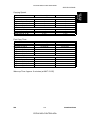
1.2 GENERAL SPECIFICATIONS
Configuration:
Desk Top
Copy Process:
Dry Electrostatic Transfer System
Resolutions:
400 dpi
Gradations:
256 gradations
Originals:
Sheet/Book/Object
Original Size:
Maximum 11" x 17" /A3
Copy Paper Size:
Paper Tray Feed
Bypass Feed
Maximum
11" x 17" /A3
11" x 17" /A3
Minimum
51/2 x 81/2 /A5(S)
51/2 x 81/2 /A5(L/S), A6(L)
17 to 24 lbs
14 to 43 lbs
64 to 90 g/m2
52 to 157 g/m2
17 to 28 lbs
64 to 104 g/m2
Copy Paper Weight:
Paper Tray Feed
Bypass Feed
Auto Duplex
Tray
Reproduction Ratios:
Enlargement
Full size
Reduction
Programmable
81/2" x 11"/11" x 17" version
121, 129, 155, 200, 400%
100%
25, 50, 65, 74, 77, 85, 93%
2 user ratios
A4/A3 version
115, 122, 141, 200, 400%
100%
25, 50, 65, 71, 75, 82, 93%
2 user ratios
Zoom: From 25% to 400 % in 1% steps.
A166/A187/A189
1-2
CÓPIA NÃO CONTROLADA
SM
SPECIFICATIONS
Copying Speed:
Normal Mode
Full Color (4 scans)
Single Color (C, M Y, K)
Single Color (R, B)
Single Color (G)
OHP/Thick Paper Mode
Full Color (4 scans)
Single Color (C, M Y, K)
Single Color (R, G, B)
81/2" x 11" (S) /A4
11" x 17"/A3
3 cpm
21 cpm
4 cpm
3 cpm
1.5 cpm
11 cpm
3 cpm
2.5 cpm
1.5 cpm
2.5 cpm
2 cpm
1 cpm
1.5 cpm
1 cpm
81/2" x 11" (S) /A4
11" x 17" /A3
32 seconds
15 seconds
20 seconds
25 seconds
30 seconds
52 seconds
20 seconds
20 seconds
35 seconds
40 seconds
50 seconds
35 seconds
35 seconds
40 seconds
45 seconds
70 seconds
45 seconds
45 seconds
55 seconds
60 seconds
First Copy Time:
Normal Mode
Full Color (4 scans)
Single Color (K)
Single Color (C, M, Y)
Single Color (R, B)
Single Color (G)
OHP/Thick Paper Mode
Full Color (4 scans)
Single Color (K)
Single Color (C, M, Y)
Single Color (R, B)
Single color (G)
Warm-up Time: Approx. 6 minutes (at 68°F / 20°C)
SM
1-3
CÓPIA NÃO CONTROLADA
A166/A187/A189
Overall
Machine
Information
CÓPIA NÃO CONTROLADA
SPECIFICATIONS
CÓPIA NÃO CONTROLADA
Duplexing:
Basic Manual Duplex
Model (A166):
Manual Duplexing in full color and Single
Color mode
Basic Auto Duplex
Model (A187):
Manual & Auto Duplexing in Full Color and
Single Color mode
Edit Auto Duplex Model Manual & Auto Duplexing in Full Color and
(A189):
Single Color mode
Duplex can be done on 64-104 g/m2 (17-28lb
bond) paper.
Manual Duplexing can be done through the
By-pass table only, and the user should press
the Duplex Side 2 key before copying the
reverse side.
Non-Reproduction Area:
Leading Edge:
0.2" ± 0.08" (5 mm ± 2 mm)
Side:
0.08" ± 0.08" (2 mm ± 2 mm)/
Total less than 0.16" (4 mm)
Trailing Edge
Front side 2.5 mm ± 2.0 mm
Back side 6.0 ± 2.0 mm
(back side trailing edge is adjustable by SP
mode from 0.5 to 10 mm)
Copy Number Input:
Number keys, 1 to 99
Copy Number Input
(Auto Duplex):
Number keys
Single Color - 1 to 50: smaller than A3, 11" x 17"
1 to 30: A3, 11" x17"
Full Color
1 to 20: all sizes
Image Density:
Auto/Manual (7 steps)
Automatic Reset:
Yes (10 to 900 seconds or Off)
Paper Capacity:
Tray:
250 sheets x 1 tray
(Basic Manual Duplex Model: A166)
By-pass:
40 sheets Normal paper (80 g/m2)
20 sheets OHP
1 sheet
Adhesive paper
A166/A187/A189
1-4
CÓPIA NÃO CONTROLADA
SM
CÓPIA NÃO CONTROLADA
Black:
Toner Addition (300 g/cartridge)
Color (Y, M, C):
Toner Addition (100 g/cartridge)
Toner Type E for C, M, Y; Ex for BK
Cyan - EDP# 889766
Magenta - EDP# 889765
Yellow - EDP# 889764
Black - EDP# 889763
Developer Type: F all colors
Cyan - EDP# 889762
Magenta - EDP# 889761
Yellow - EDP# 889760
Black - EDP# 889759
Copy Tray Capacity:
100 sheets (11" x 17"/A3 and smaller)
Power Source:
120V/60Hz, 220-240V/50,60 Hz
Maximum Power
Consumption:
1.5 kVA
Dimensions (with Platen Cover):
Basic Manual Duplex
(A166)
Basic Auto Duplex
(A187)
Edit Auto Duplex
(A189)
Width
620 mm
24.4"
620 mm
24.4"
620 mm
24.4"
Depth
700 mm
27.5"
700 mm
27.5"
750 mm
29.5"
Height
632 mm
24.9"
632 mm
24.9"
632 mm
24.9"
Weight:
Manual Duplex: 105 kg (231.3 lb)
Auto Duplex: 109 kg (240.1 lb)
Optional Equipment:
Automatic Document Feeder: ARDF (A548)
Sorter Stapler: ST10 (A555)
Film Projector: SPU 3 (A718)
Holder for Film Projector Unit: Type B (A579)
Paper Tray Unit (3 Trays & 2 Trays):
PS290/PS280 (A549/A550)
Key Counter (Procure locally)
SM
1-5
CÓPIA NÃO CONTROLADA
A166/A187/A189
Overall
Machine
Information
Toner Replenishment:
SPECIFICATIONS
SPECIFICATIONS
CÓPIA NÃO CONTROLADA
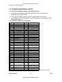
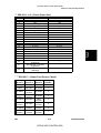
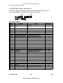
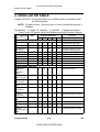
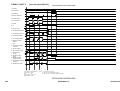
1.3 DETECTABLE ORIGINAL SIZE BY PLATEN/ARDF
Size
(width x length)
[mm]
A3 (297 x 420)L
B4 (257 x 364)L
A4 (210 x 297)L
A4 (297 x 210)S
B5 (182 x 257)L
B5 (257 x 182)S
A5 (148 x 210)L
A5 (210 x 148)S
B6 (128 x 182)L
B6 (182 x 128)S
11" x 17" (DLT)
11" x 15"
10" x 14"
8.5" x 14" (LG)
8.5" x 13" (F4)
8.25" x 13"
8" x 13"(F)
8.5" x 11" (LT)
11" x 8.5" (LT)
8" x 10.5"
8" x 10"
5.5" x 8.5" (HLT)
8.5" x 5.5" (HLT)
A6 (105 x 148)L
Platen
ARDF
Inch version
Metric version
Inch version
Metric version
No
No
No
No
No
No
No
No
No
No
Yes
No
Yes
Yes
No
No
No
Yes
Yes
No
No
No*
Yes
No
Yes
Yes
Yes
Yes
Yes
Yes
No*
Yes
No
No
No
No
No
No
Yes
No
No
No
No
No
No
No
No
No
No
No
Yes
Yes
No
No
No
No
No
No
Yes
Yes
Yes
Yes
No
No
Yes
Yes
Yes
No
Yes
Yes
Yes
No
Yes
Yes
Yes
Yes
Yes
Yes
Yes
Yes
Yes
Yes
Yes
No
No
No
Yes
No
No
Yes
Yes
No
No
No
No
No
* : For A5 lengthwise/HLT, SP4-303 can be used to select "Cannot detect
original size" or "A5 lengthwise/5.5" x 8.5"(HLT)".
A166/A187/A189
1-6
CÓPIA NÃO CONTROLADA
SM
SPECIFICATIONS
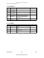
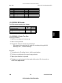
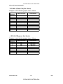
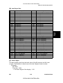
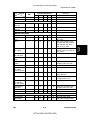
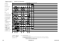
1.4 COPY PAPER SIZE
Size
(width x length)
[mm]
A3 (297 x 420)L
B4 (257 x 364)L
A4 (210 x 297)L
A4 (297 x 210)S
B5 (182 x 257)L
B5 (257 x 182)S
A5 (148 x 210)L
A5 (210 x 148)S
B6 (128 x 182)L
B6 (182 x 128)S
11" x 17" (DLT)
11" x 15"
10" x 14"
8.5" x 14" (LG)
8.5" x 13" (F4)
8.25" x 13"
8" x 13"(F)
8.5" x 11" (LT)
11" x 8.5" (LT)
8" x 10.5"
8" x 10"
5.5" x 8.5" (HLT)
8.5" x 5.5" (HLT)
A6 (105 x 148)L
Trays in the main body
Paper Tray
Inch
Metric
version
version
No
Yes
No
Yes
Yes
Yes
Yes
Yes
No
Yes
No
Yes
No
No
No
Yes
No
No
No
No
Yes
Yes
Yes
No
Yes
No
Yes
No
Yes
Yes
No
No
No
No
Yes
Yes
Yes
Yes
No
No
Yes
No
No
No
Yes
No
No
No
Duplex Tray
Inch
Metric
version
version
Yes
Yes
Yes
Yes
Yes
Yes
Yes
Yes
No
Yes
No
Yes
No
No
Yes
Yes
No
No
No
No
Yes
Yes
Yes
No
Yes
No
Yes
No
Yes
Yes
Yes
Yes
Yes
Yes
Yes
Yes
Yes
Yes
Yes
No
Yes
Yes
No
No
Yes
Yes
No
No
Bypass
All
versions
Yes
Yes
Yes
Yes
Yes
Yes
Yes
Yes
Yes
No
Yes
Yes
Yes
Yes
Yes
Yes
Yes
Yes
Yes
Yes
Yes
Yes
Yes
Yes
Optional
S.Stapler
Yes
Yes
Yes
Yes
Yes
Yes
Yes (1)
Yes (2)
Yes (1)
No
Yes
Yes
Yes
Yes
Yes
Yes
Yes
Yes
Yes
Yes
Yes
Yes (1)
Yes (2)
Yes (2)
Yes (1): Stapling is not allowed.
Yes (2): Using the Proof Tray only. Sorter bins cannot be used.
SM
1-7
CÓPIA NÃO CONTROLADA
A166/A187/A189
Overall
Machine
Information
CÓPIA NÃO CONTROLADA
CÓPIA NÃO CONTROLADA
SPECIFICATIONS
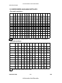
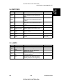
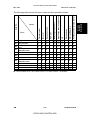
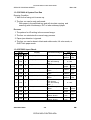
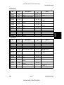
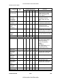
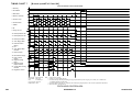
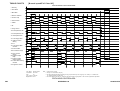
1.5 PAPER SIZES AVAILABLE WITH APS
– For metric machines –
A3
200 173 163 141 122 115 100
~
~
~
~
~
~
~
174 164 142 123 116 101 94
–
–
–
–
–
–
A3
B4
–
–
–
–
–
A3
B4
A4L
–
–
–
A3
B4
–
A4L
B5L
A5L
A4S
B5S
A5S
8.5
x 11
11
x 8.5
8.5
x 13
11
x 15
–
A3
–
–
–
–
–
B4
–
–
–
–
–
–
–
–
–
–
A3 B4
– A4L B5L
– A4L B5L – A5L
–
–
–
– A4S
–
–
– A4S B5S
– A4S B5S – A5S
–
–
–
– 8.5
x11
–
–
–
– 11x
8.5
–
–
A3
– 8.5
x 13
–
–
–
– 11x
15
93
~
88
–
87
~
83
B4
82
~
76
–
75 71 65 61 57 50
~
~
~
~
~
~
72 66 62 58 51
– A4L 8.5 B5L – A5L
x 13
–
– A4L 8.5 B5L –
– A5L –
x 13
8.5 B5L –
– A5L –
–
–
–
x 13
–
– A5L –
–
–
–
–
–
–
–
–
–
–
–
–
–
–
– B5S –
– A5S –
–
–
–
–
– A5S –
–
–
–
–
–
–
–
–
–
–
–
–
–
–
–
–
–
–
–
–
–
–
–
–
–
–
–
–
–
–
–
A4L B5L
–
–
–
–
–
–
–
–
–
–
–
A5L
–
–
–
–
–
: Not allowed in platen cover mode. L: Lengthwise S: Sideways
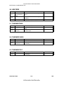
– For inch machines –
11x17
200
~
177
–
176
~
156
–
155
~
130
–
129
~
122
–
11x15
–
–
–
–
–
8.5x14
–
–
–
–
8.5x11
–
–
11
x17
–
5.5x8.5
8.5x5.5
11
x17
–
11
x15
–
8.5
x14
–
11x8.5
–
–
–
8.5
x11
11
x8.5
–
8x10
–
–
–
11x17
10x14
–
–
–
–
–
8x13
–
–
–
11x17
–
11x17
121 100
93
85
~
~
~
~
101
94
86
78
– 11x17 11x17 11x15
11x15 11x15
8.5
x14
8.5
x11
–
5.5
x8.5
–
8.5
x5.5
–
11
x8.5
10x14 8x10
–
77
74
65
~
~
~
75
66
51
8.5
–
8.5
x14
x11
8.5 8.5x11 –
x14
8.5
–
–
x11
–
–
5.5
x8.5
–
–
–
50
~
5.5
x8.5
5.5
x8.5
5.5
x8.5
–
–
–
–
–
–
–
–
–
–
–
–
–
–
–
–
–
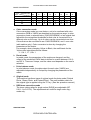
–
–
–
–
–
10x14
–
–
8.5
x11
–
–
8x13
8.5
x14
–
8.5
x5.5
5.5
x8.5
–
–
5.5
x8.5
–
–
5.5
x14
–
: Not allowed in platen cover mode.
A166/A187/A189
1-8
CÓPIA NÃO CONTROLADA
SM
SPECIFICATIONS
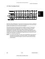
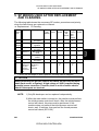
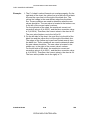
NOTE: 1) The tables show which copy paper size is selected for each
original size for zoom ratios from 50 to 200 %.
2) When a zoom ratio is specified, APS automatically selects a
paper size that can guarantee the quality of the magnified copy
image if there is a paper size available for the equivalent
standard reproduction ratio.
3) If paper of the detected size has run out, the machine displays the
message "Set xx
paper in tray" and stops the job (copying is
enabled).
4) For "–" in the above tables, the machine displays the message
"Cannot detect original size" and stops the job (copying is
enabled). The selected paper feed tray does not change.
5) When 49% or less or 201% or more is selected, APS works in the
same way as described in Note 4 above.
6) APS also supports the by-pass feed table (except for
non-standard paper sizes). When a selected paper size can only
be fed from the by-pass feed table, the machine displays a
warning to instruct the user to use the by-pass feed table.
7) APS does not support A6 and B6 sizes.
$
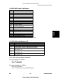
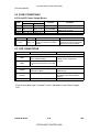
1.6 NOISE EMISSION
Sound pressure level (The measurements are made in accordance with ISO
7779 at the operator positions.)
Copier only
Less than 61 dB (A)
Full system*
Less than 65 dB (A)
* Full system: Copier with document feeder, 500 sheets x 3 trays unit, FPU,
and a sorter stapler.
Sound power level (The measurements are made in accordance with ISO
7779.)
Stand-by
Copying
(This value is for the
black copy mode.)
Copier only
Less than 54 dB (A)
Full system*
Less than 58 dB (A)
Less than 67 dB (A)
Less than 71 dB (A)
* Full system: Copier with document feeder, 500 sheets x 3 trays unit, FPU,
and a sorter stapler.
SM
1-9
CÓPIA NÃO CONTROLADA
A166/A187/A189
Overall
Machine
Information
CÓPIA NÃO CONTROLADA
CÓPIA NÃO CONTROLADA
SPECIFICATIONS
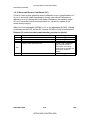
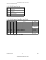
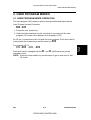
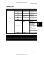
1.7 POWER CONSUMPTION
(1) Maximum power consumption
1.5 kVA
(2) Average power consumption
A189 Copier
0.25 kW
1.25 kW
1.15 kW
Value for standby
minus 7 W
Standby
Warm-up
Copying
Energy Saver
Mode
A189 Copier +
DJF + Sorter
0.5 kW
1.25 kW
1.15 kW
Value for standby
minus 7 W
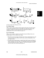
NOTE: 1) Copying was done in the 1C (A3) repeat mode.
2) The power consumption in energy saver mode was measured
with the fusing lamp off.
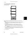
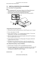
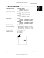
1.8 DISPLAY EDITOR SPECIFICATION
Scanned image
Displayed image
Area specification
procedure
A166/A187/A189
•
•
•
•
•
The copier’s scanner scans the image.
Maximum A3/DLT (11" x 17"): Reduced image display
144 x 192 mm, 16-gradation (4 bit/pixel) monochrome
640 x 480 dots, 0.33 mm/pixel
Reduces the dpi of scanned images to approximately 33 dpi and
displays the entire image.
• Zoom display: 3 levels (50 dpi, 67 dpi, 100 dpi)
• Display processing time: 2 seconds or less
• Move the arrow in the screen by using the cursor key and enter a
point by pressing the coordinate entry key.
1-10
CÓPIA NÃO CONTROLADA
SM
CÓPIA NÃO CONTROLADA
MACHINE CONFIGURATION
Overall
Machine
Information
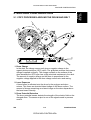
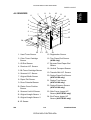
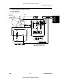
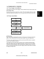
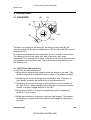
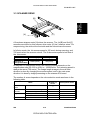
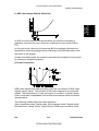
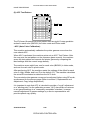
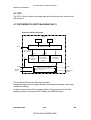
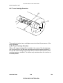
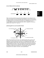
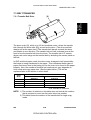
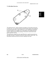
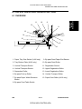
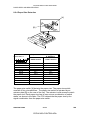
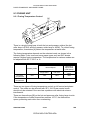
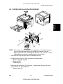
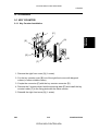
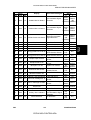
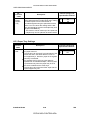
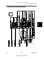
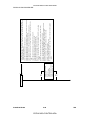
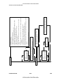
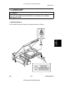
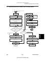
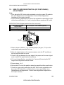
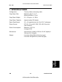
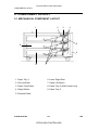
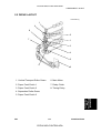
2. MACHINE CONFIGURATION
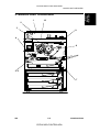
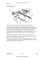
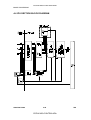
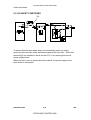
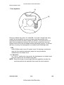
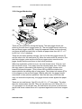
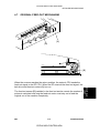
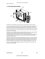
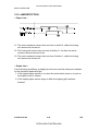
2.1 COPY PROCESSES AROUND THE DRUM AND BELT
2
1
11
3
10
8
7
4
5
6
9 13
12
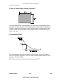
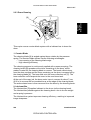
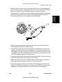
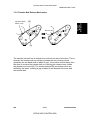
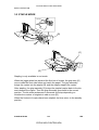
1. Drum Charge
In the dark, the charge corona unit gives a negative charge to the
organic photoconductive (OPC) drum. The grid plate ensures that corona
charge is applied uniformly. The charge remains on the surface of the
drum because the OPC layer has a high electrical resistance in the dark.
The amount of negative charge on the drum is proportional to the
negative voltage applied to the drum charge corona wire and casing.
2. Laser Exposure
A laser beam is reflected onto the drum by the polygon and drum
mirrors. This forms an electrical latent image on the drum surface. The
amount of charge remaining as a latent image on the drum depends on
the laser beam intensity.
3. Drum Potential Detection
The drum potential sensor detects the strength of the electric field on the
charged drum. The sensor output is one of the signals used in process
control.
SM
1-11
CÓPIA NÃO CONTROLADA
A166/A187/A189
CÓPIA NÃO CONTROLADA
MACHINE CONFIGURATION
4. Development
The negatively charged toner is attracted to the latent image on the drum
surface. Toner particles are electrostatically attracted to the area of the
drum surface where the laser reduced the negative charge on the drum.
The development unit is a revolver-type, containing separate
development sections for each color toner.
5. Image Density Detection
When the laser forms a sensor pattern on the drum surface, the ID
sensor measures the image density of these patterns. The output signal
is used in process control to regulate toner supply.
6. Pre-transfer Lamp
After development, the pre-transfer lamp reduces the potential of the
image background, right before the first belt transfer (in 2C/3C/4C mode).
This ensures that electrostatic attraction between belt and drum is about
the same for each color toner transfer, which ensures that the color toner
images are synchronized properly.
7. Belt Transfer
Toner on the drum is attracted to the transfer belt by the belt corona unit.
8. Belt Lubrication
The transfer belt lubricant brush applies a small amount of lubricant to
the surface of the transfer belt. This aids the belt cleaning blade in
removing waste toner from the transfer belt.
9. Belt Cleaning
The cleaning blade removes any toner on the belt after paper transfer.
10. Drum Cleaning
The drum cleaning brush roller removes remaining toner from the drum.
The cleaning brush also applies lubricant. This aids in drum cleaning.
11. Quenching
The light from the quenching lamp electrically neutralizes the charge on
the drum surface. This prepares the drum for the next copy cycle.
12. Paper Transfer
When all toner has been transferred from the drum to the transfer belt,
the charged toner on the transfer belt is attracted to the paper by the
paper transfer unit. This charge is applied to the underside of the paper.
13. Paper Separation
The copy paper separates from the transfer belt due to the belt’s
curvature. This curvature allows the paper to naturally fall away from the
transfer belt. The discharge brush aids in the separation process by
discharging any remaining electric charge from the paper.
A166/A187/A189
1-12
CÓPIA NÃO CONTROLADA
SM
CÓPIA NÃO CONTROLADA
MAJOR UNIT OVERVIEW
1
Overall
Machine
Information
3. MAJOR UNIT OVERVIEW
10
2
3
9
4
8
5, 6
7
SM
1-13
CÓPIA NÃO CONTROLADA
A166/A187/A189
MAJOR UNIT OVERVIEW
CÓPIA NÃO CONTROLADA
1. Copier
1. Dimensions (W x D x H):
Basic machine - 620 x 700 x 632 mm [24.4"x27.6"x25.2"] (with paper
tray unit: 620 x 700 x 1010) [24.4"x27.6"x40.1"]
Edit machine - 620 x 750 x 632 mm [24.4"x29.8"x25.2"] (with paper tray
unit: 620 x 750 x 1010) [24.4"x29.8"x40.1"]
2. The printer unit, system control unit, and scanner unit are independent
modules connected with an interface.
2. Scanner Unit
1. 400 dpi (8 bits/dot) scanning in both main and sub scan directions
2. 3-line CCD with reduction optics
3. Exposure lamp: Halogen lamp
4. 5-phase stepper motor drive
3. Drum Unit
1. The drum unit contains the photoconductor drum, charge corona unit,
and cleaning unit
2. Charge corona unit: Single scorotron charge
3. Quenching Lamp: Red LEDs
4. Drive: Synchronized with the transfer belt (dc brushless motor and
flywheel); full speed = 105 mm/s
5. Potential sensor and ID sensor included
4. Fusing and Paper Exit Section
1. Fusing: Silicone roller fusing (both hot and pressure rollers)
2. Oil application method: Double roller
3. Cleaning: Roller cleaning for the hot roller
Cleaning blade for the pressure roller
4. OHP/Thick paper mode: Half speed (52.5 mm/s)
5. Development and Toner Supply
1. Development: Two-component magnetic brush development
2. Development switching: Revolver System
3. Image density control: ID sensor and Potential sensor (Process control)
4. Toner supply
Black: Screw-in bottle (300 g)
Color: Sector cartridge (100 g)
5. Toner supply unit: Front of development unit (rotation type)
A166/A187/A189
1-14
CÓPIA NÃO CONTROLADA
SM
CÓPIA NÃO CONTROLADA
MAJOR UNIT OVERVIEW
Overall
Machine
Information
6. Toner and Developer
1. Color toner: Type E
2. Black toner: Type EX
3. Developer: Type F
7. Paper Feed and Transport
1. Paper Tray Unit (A166 copier only)
• Corner Separation System
• Front loading tray (250 sheets) and By-pass table
2. Transport: Transport belt with fan
3. Duplex unit (A187, A189 copier only)
• Duplex unit and By-pass table
4. Paper Tray Unit (option): • 500 sheets x 3 trays (FRR Feed System)
• 500 sheets x 2 trays (FRR Feed System)
8. Transfer and Belt Drive
1. Transfer belt: Full time contact with the drum
2. Belt transfer: Single corona charge
3. Paper transfer: Single corona charge
4. Registration: Synchronization by the transfer belt H.P. sensor
5. Drive: Synchronized with the drum (same motor)
6. Separation: Curvature separation + discharge brush
7. Transfer cycle: 1 belt rotation/A4
8. Belt cleaning: Counter blade
9. Lubrication: Brush roller with lubricant bar
9. Printer Unit
1. Optics: 6-sided polygon mirror + 2 fθ lenses and BTL
2. Polygon motor (16535 rpm), with ball bearing
3. Resolution: 400 dpi
4. Modulation: PM and PWM
10. System Control Unit (SCU)
1. Basic machine: The SCU is on the back side of the operation panel
(20-digit 2-line LCD)
2. Edit machine: The SCU is under the scanner unit and connected to the
touch panel display (640 x 480 dots).
Note for Ricoh Corporation:
A166 = model Aficio Color 2003
A187 = model Aficio Color 2103
A189 = model Aficio Color 2203
SM
1-15
CÓPIA NÃO CONTROLADA
A166/A187/A189
CÓPIA NÃO CONTROLADA
PARTS LAYOUT
4. PARTS LAYOUT
4.1 MECHANICAL COMPONENT LAYOUT
5
6
8
7
9 10 11 12 13 14
15
4
16
17
19
3
20
2
21
18
22
1
25
26
24
23
1. Paper Tray (A166)
Duplex Tray
(A187/189)
10. Charge Corona Unit 20. OPC Drum
11. Lens
21. Registration Rollers
2. Pressure Roller
12. 2nd fθ Lens
22. Relay Roller
3. Hot Roller
13. CCD Board
4. 2nd Scanner
14. 1st fθ Lens
23. Belt Transfer
Charge Unit
5. 1st Scanner
15. Polygon Mirror
6. Development Unit
16. Drum Cleaning Unit 25. Belt Cleaning Unit
7. Drum Mirror
17. Lubricant Brush
8. Toner Shield Glass
18. By-pass Feed Table
9. Barrel Toroidal
Lens (BTL)
19. Transfer Belt
A166/A187/A189
1-16
CÓPIA NÃO CONTROLADA
24. Paper Transfer
Charge Unit
26. Transport Belt
SM
CÓPIA NÃO CONTROLADA
PARTS LAYOUT
6
5
7
Overall
Machine
Information
4.2 PCB (A166/A187 COPIERS)
8
4
9
3
10
2
11
1
12
13
18
14
16
17
1. RAM Board
11. I/O Control Board 2
2. SCU Board
12. By-pass Paper Width
Detection Board
3. AC Drive/DC Power
Supply Board
13. I/O Control Board 1
14. High Voltage Supply
Board
4. Operation Panel
5. Scanner Motor Drive
Board
15. Laser Synchronizing
Detector Board 2
6. Scanner IPU Board
7. CCD Board
16. Laser Synchronizing
Detector Board 1
8. Lamp Regulator
17. LD Drive Board
9. IDU Board
18. Duplex Control Board
(Except A166)
10. Main Control Board
SM
15
1-17
CÓPIA NÃO CONTROLADA
A166/A187/A189
PARTS LAYOUT
CÓPIA NÃO CONTROLADA
4.3 PCB (A189 COPIER)
20
19
21
23
22
19. SCU Board
20. Operation Panel
21. Extended IPU Board
22. Duplex Control Board
23. RAM Board
A166/A187/A189
1-18
CÓPIA NÃO CONTROLADA
SM
CÓPIA NÃO CONTROLADA
PARTS LAYOUT
Overall
Machine
Information
4.4 SOLENOIDS AND CLUTCHES
4
3
5
6
2
7
8
1
9
10
1. Transfer Belt Cleaning SOL
6. Registration CL
2. Toner Supply Release SOL
7. Main By-pass Feed Pick-up
SOL
3. Junction Gate SOL
(A187/A189 only)
8. By-pass Feed CL
4. Sub By-pass Feed Pick-up
SOL
9. Paper Feed CL (A166 only)
10. Vertical Transport CL
5. Transfer Belt Lubricant SOL
SM
1-19
CÓPIA NÃO CONTROLADA
A166/A187/A189
CÓPIA NÃO CONTROLADA
PARTS LAYOUT
4.5 SWITCHES AND HEATERS
11
9
12
13
10
14
8
15
7
16
6
5
17
4
18
3
19
2
20
1
21
22
1. Lower Tray Heater
2. Pressure Roller Thermofuse
12. Optics Anticondensation
Heater
13. Fusing Thermistor
3. Pressure Roller Lamp
14. Charge Corona Unit
4. Fusing Lamp
5. Pressure Roller Thermistor
15. Quenching Lamp
6. Main Switch
16. Tray Paper Size SW
(A166 only)
7. Front Door Switch
17. Paper Transfer Charge Unit
8. Fusing Thermofuse
18. Belt Transfer Charge Unit
9. Paper Exit Door Switch
(A187/A189 only)
19. Drum Heater
20. By-pass Feed Table SW
10. Exposure Lamp
21. Vertical Transport SW
11. Thermostat
22. Pre-transfer Lamp
A166/A187/A189
1-20
CÓPIA NÃO CONTROLADA
SM
CÓPIA NÃO CONTROLADA
8
7
6
9
10
11
12
13
5
14
4
15
3
16
2
17
1
18
24
23
22
21
20
19
1. Used Toner Sensor
15. Registration Sensor
2. Color Toner Cartridge
Sensor
16. Tray Paper End Sensor
(A166 only)
3. Oil End Sensor
17. By-pass Feed Paper End
Sensor
4. Revolver H.P. Sensor
18. Vertical Transport Sensor
5. Bk Toner Cartridge Sensor
19. Transfer Belt H.P. Sensor
6. Scanner H.P. Sensor
20. Duplex Paper End Sensor
(A187/A189 only)
7. Original Width Sensor
8. Paper Exit Sensor
21. Duplex Turn Sensor
(A187/A189 only)
9. Drum Potential Sensor
10. Platen Cover Position
Sensor
22. Duplex Entrance Sensor
(A187/A189 only)
11. Scanner Unit Lift Sensor
23. Side Fence Jogger HP
Sensor (A187/A189 only)
12. Original Length Sensor 1
24. End Fence Jogger HP
Sensor (A187/A189 only)
13. Original Length Sensor 2
14. ID Sensor
SM
1-21
CÓPIA NÃO CONTROLADA
A166/A187/A189
Overall
Machine
Information
4.6 SENSORS
PARTS LAYOUT
CÓPIA NÃO CONTROLADA
PARTS LAYOUT
4.7 MOTORS
3
2
4
5
6
1
10
7
8
9
1. Toner Supply Motor
7. Main Motor
2. Scanner Motor
8. Duplex Feed Motor
(A187/A189 only)
3. Revolver Drive Motor
9. Side Fence Jogger Motor
(A187/A189 only)
4. Development Drive Motor
5. Polygon Motor
6. Drum Motor
A166/A187/A189
10. End Fence Jogger Motor
(A187/A189 only)
1-22
CÓPIA NÃO CONTROLADA
SM
CÓPIA NÃO CONTROLADA
PARTS LAYOUT
7
Overall
Machine
Information
4.8 DRIVE LAYOUT
8
6
9
5
4
10
3
11
2
1
1. Paper Feed Clutch
7. Transfer Belt Drive Gear
2. Vertical Transport Clutch
8. Development Drive Gear
3. Registration Clutch
9. Revolver Drive Gear
4. By-pass Feed Clutch
10. Transport Unit Drive Gear
5. Drum Drive Gear
11. Fusing Unit Drive Gear
6. Transfer Belt Lubricant
Gear
SM
1-23
CÓPIA NÃO CONTROLADA
A166/A187/A189
CÓPIA NÃO CONTROLADA
PARTS LAYOUT
4.9 FANS AND AIR FLOW
9
8
10
7
11
6
12
5
4
13
3
14
2
1
15
9. Exhaust Fan
1. Development Inlet Fan
2. Transport Fan 1
10. Fusing Fan
3. Transport Fan 2
11. Charge Inlet Fan
4. Front Power Supply
Board Fan
12. Optics Exhaust Fan
5. Paper Exit Fan
13. Scanner Board Cooling
Fan
6. Optics Cooling Fan 1
14. Rear Transfer Fan
7. Optics Cooling Fan 2
15. Front Transfer Fan
8. Rear Power Supply Board
Fan
A166/A187/A189
1-24
CÓPIA NÃO CONTROLADA
SM
CÓPIA NÃO CONTROLADA
PARTS LAYOUT
Overall
Machine
Information
4.10 COUNTERS (A166/A187 COPIERS)
1
2
1. Main Counter
2. Back-up Counter (stored in the RAM board on the SCU board)
SM
1-25
CÓPIA NÃO CONTROLADA
A166/A187/A189
CÓPIA NÃO CONTROLADA
PARTS LAYOUT
4.11 COUNTER (A189 COPIER)
2
1
1. Main Counter
2. Back-up Counter (stored in the RAM board on the SCU board)
A166/A187/A189
1-26
CÓPIA NÃO CONTROLADA
SM
CÓPIA NÃO CONTROLADA
5. ELECTRICAL COMPONENT LIST
5.1 PRINTED CIRCUIT BOARDS
Symbol
Name
PCB1 Lamp regulator
Scanner motor drive
PCB2
board
CCD board
PCB3
PCB4
AC drive/
DC power suppy
Scanner IPU board
PCB5
PCB6
Main control board
I/O control board 1
PCB7
I/O control board 2
PCB8
PCB9
PCB10
PCB11
PCB12
PCB13
PCB14
PCB15
PCB16
PCB17
LD drive board
Laser synchronizing
detector board 1
Laser synchronizing
detector board 2
IDU board
By-pass paper width
detection board
High voltage supply
board
System control unit
(SCU) board
RAM board
Operation panel
Extended IPU board
PCB18
Duplex control board
Function
Supplies dc power for the exposure lamp.
Supplies dc power for the scanner motor.
Converts the light reflected from the original
into signals.
Supplies ac and dc power.
Converts the RGB image signal from the
CCD to a KCMY signal and sends it to the
printer and SCU.
Controls the printer sequence.
Interfaces the sensors, clutches, solenoids
and motors in the printer module with the
main control board. Includes temperature
and humidity sensors.
Interfaces the sensors, clutches, solenoids
and motors in the printer module with the
main control board.
Controls the LD output.
Detects laser main scan synchronization
while writing the latent image to the drum.
Detects laser main scan synchronization
while writing the latent image to the drum.
Discriminates image for anti-counterfeiting
Detects the paper width in the by-pass feed
table.
Supplies power to the corona units.
Controls the system.
Stores the copy process data and counters.
Used to operate the copier.
Converts scanned image data and sends it
to SCU for the display. Performs image
processing on an area specified in the
display.
Controls the duplex unit.
PCB19
SM
Remarks
1-27
CÓPIA NÃO CONTROLADA
A189
copier
only
A187/A189
copiers
only
A166/A187/A189
Overall
Machine
Information
ELECTRICAL COMPONENT LIST
CÓPIA NÃO CONTROLADA
ELECTRICAL COMPONENT LIST
5.2 SOLENOIDS
Symbol
SOL1
SOL2
SOL3
SOL4
SOL5
SOL6
Name
Sub by-pass feed
pick-up solenoid
Main by-pass feed
pick-up solenoid
Toner supply
release solenoid
Transfer belt
cleaning solenoid
Transfer belt
lubricant solenoid
Junction gate
solenoid
Function
Lowers the pick-up roller.
Remarks
Lowers the pick-up roller.
Releases the toner supply motor.
Controls the contact and release
operation of the belt cleaning blade.
Controls the contact and release
operation of the lubrication brush on
the transfer belt.
Raises the junction gate for the duplex
copier.
A187/A189 copier
only
5.3 CLUTCHES
Symbol
CL1
CL2
CL3
CL4
Name
Function
Remarks
By-pass feed clutch Transmits the drive to the by-pass feed
section.
Registration clutch Transmits the drive to the registration
rollers.
Vertical transport
Transmits the drive to the vertical
clutch
transport section.
Paper feed clutch Transmits the drive to the paper feed
A166 copier only
section.
A166/A187/A189
1-28
CÓPIA NÃO CONTROLADA
SM
CÓPIA NÃO CONTROLADA
5.4 SWITCHES
Symbol
Name
SW1 Main switch
Front door switch
SW2
SW3
SW4
SW5
SW6
SW7
SW8
SW9
Function
Remarks
Turns the power to the copier on or off.
Opens the dc line to the high voltage
supply board when the front door is
open.
Front door switch Opens the dc line to the main control
board and LD unit when the front door
is open.
Front door switch Opens the dc line to the main control
board and LD unit when the front door
is open.
Front door switch Opens the dc line to I/O control board 2
when the front door is open.
Vertical transport
Detects if the vertical transport door is
switch
open or closed.
By-pass feed table Detects if the by-pass feed table is
switch
open or closed.
Tray paper size
Detects the size of paper on the paper A166 copier only
switch
tray.
Paper exit door
Detects if the paper exit door is open or A187/A189
switch
closed.
copiers only
5.5 LAMPS
Symbol
Name
L1
Fusing lamp
Pressure roller
L2
lamp
Exposure lamp
L3
L4
L5
SM
Quenching lamp
(QL)
Pre-transfer lamp
(PTL)
Function
Provides heat to the hot roller.
Provides heat to the pressure roller.
Remarks
Applies high intensity light to the
original for exposure.
Neutralizes any charge remaining on
the photoconductor.
Reduces the charge remaining on the
drum before the transfer process is
started (except for the image area).
1-29
CÓPIA NÃO CONTROLADA
A166/A187/A189
Overall
Machine
Information
ELECTRICAL COMPONENT LIST
CÓPIA NÃO CONTROLADA
ELECTRICAL COMPONENT LIST
5.6 HEATERS
Symbol
H1
H2
H3
Name
Optics
anticondensation
heater
Drum heater
Function
Prevents moisture from forming on the
optics.
Remarks
Prevents moisture from forming around
the drum.
Keeps paper dry on the paper feed tray.
Lower tray heater
5.7 THERMISTORS
Symbol
TH1
TH2
Name
Fusing thermistor
Function
Monitors the temperature of the hot
roller.
Monitors the temperature of the
pressure roller.
Pressure roller
thermistor
Remarks
5.8 THERMOFUSES
Symbol
Name
Function
TF1
Fusing thermofuse Protects the hot roller from overheating.
Pressure roller
Protects the pressure roller from
TF2
thermofuse
overheating.
Remarks
5.9 THERMOSTAT
Symbol
TS1
Name
Thermostat
A166/A187/A189
Function
Prevents the halogen lamp from
overheating.
1-30
CÓPIA NÃO CONTROLADA
Remarks
SM
CÓPIA NÃO CONTROLADA
5.10 SENSORS
Symbol
S1
S2
S3
S4
S5
S6
S7
S8
S9
S10
S11
S12
S13
S14
S15
S16
S17
S18
S19
S20
S21
S22
S23
S24
SM
Name
Platen cover
position sensor
Scanner unit lift
sensor
Scanner HP sensor
Transfer belt HP
sensor
Paper exit sensor
Color toner
cartridge sensor
Drum potential
sensor
ID sensor
Function
Detects if the platen cover is up or
down.
Detects if the scanner unit is lifted or
not.
Detects the scanner home position.
Detects the transfer belt mark.
Detects a paper jam at the paper exit.
Detects the presence of color toner
cartridges.
Detects the potential on the drum
surface for process control.
Detects the density of the sensor
pattern image on the drum for process
control.
Revolver HP
Detects if the revolver is at the home
sensor
position.
Bk toner cartridge Detects if the black toner cartridge is
sensor
installed.
Registration sensor Detects a paper jam at the registration
section.
Vertical transport
Detects a paper jam at the vertical
sensor
transport section.
Used toner sensor Detects if the used toner tank is full.
By-pass feed
Detects if there is paper on the by-pass
paper end sensor feed table.
Tray paper end
Detects if there is paper on the paper
sensor
feed tray.
Side fence jogger Detects the home position of the duplex
HP sensor
unit side fence.
End fence jogger
Detects the home position of the duplex
HP sensor
unit end fence.
Duplex paper end Detects if there is paper in the duplex
sensor
unit.
Duplex entrance
Detects when copy paper comes into
sensor
the duplex unit.
Duplex turn sensor Detects when copy paper is being
reversed in the duplex unit.
Original width
Detects the original width.
sensor
Original length
Detects the original length.
sensor 1
Original length
Detects the original length.
sensor 2
Oil end sensor
Detects if there is silicone oil in the oil
tank.
1-31
CÓPIA NÃO CONTROLADA
Remarks
A166 copier only
A187/A189
copiers only
A187/A189
copiers only
A187/A189
copiers only
A187/A189
copiers only
A187/A189
copiers only
A166/A187/A189
Overall
Machine
Information
ELECTRICAL COMPONENT LIST
CÓPIA NÃO CONTROLADA
ELECTRICAL COMPONENT LIST
5.11 MOTORS
Symbol
Name
M1
Scanner motor
M2
Polygon motor
Main motor
M3
M4
M5
Function
Drives the scanner.
Drives the polygon mirror.
Drives the paper feed/transport section and
fusing units.
Drives the drum and transfer belt.
Supplies toner.
Rotates the development roller.
M8
Drum motor
Toner supply motor
Development drive
motor
Revolver drive motor
Side fence jogger
motor
End fence jogger
motor
Drives the duplex unit end fences.
M9
Duplex feed motor
Drives the paper feed roller in the duplex
unit.
M6
M7
M10
Rotates the revolver unit.
Drives the duplex unit side fences.
Remarks
A187/A189
copiers
only
A187/A189
copiers
only
A187/A189
copiers
only
5.12 FAN MOTORS
Symbol
Name
FM1
Optics exhaust fan
FM2
Optics cooling fan 1
FM3
Optics cooling fan 2
Scanner board
FM4
cooling fan
FM5
Development inlet fan
FM6
Rear transfer fan
Transport fan 1
FM7
FM8
FM9
FM10
FM11
FM12
FM13
FM14
FM15
Transport fan 2
Charge inlet fan
Fusing fan
Exhaust fan
Front transfer fan
Rear power supply
board fan
Paper exit fan
Front power supply
board fan
A166/A187/A189
Function
Cools the scanner unit.
Cools the scanner unit.
Cools the scanner unit.
Cools the scanner unit.
Remarks
Cools the development unit.
Draws air from the transfer belt unit.
Draws air into attract the copy paper to the
transport belt.
Draws air into attract copy paper to the
transport belt.
Provides air flow around the charge corona
unit and ID sensor.
Cools the development unit.
Draws air out of the copier.
Draws air out of the transfer belt unit.
Cools the power supply unit.
Cools the development unit.
Cools the power supply unit.
1-32
CÓPIA NÃO CONTROLADA
SM
CÓPIA NÃO CONTROLADA
5.13 COUNTER
Symbol
CO1
SM
Name
Main counter
Function
Counts up the number of scans for Bk
and color copying.
1-33
CÓPIA NÃO CONTROLADA
Remarks
A166/A187/A189
Overall
Machine
Information
ELECTRICAL COMPONENT LIST
CÓPIA NÃO CONTROLADA
CÓPIA NÃO CONTROLADA
CÓPIA NÃO CONTROLADA
DETAILED SECTION
DESCRIPTIONS
CÓPIA NÃO CONTROLADA
CÓPIA NÃO CONTROLADA
CÓPIA NÃO CONTROLADA
CÓPIA NÃO CONTROLADA
PROCESS CONTROL
1. PROCESS CONTROL
1.1 OVERVIEW
Potential
Sensor
Detailed
Section
Descriptions
[B]
Development
Roller
Drum
[A]
[A]: Toner Supply Motor
[B]: Charge Corona Unit
SM
2-1
CÓPIA NÃO CONTROLADA
A166/A187/A189
CÓPIA NÃO CONTROLADA
PROCESS CONTROL
Rev. 1/97
This machine uses two control methods:
• Latent Image Control (every process control self check)
•
Toner Supply Control (every copy)
Latent Image Control
Latent image control controls the development potential to maintain the
density of the toner image on the drum. It does this by compensating for
variations in drum chargeability and toner chargeability.
The machine uses the drum potential sensor to measure the drum’s
response to a standard applied voltage. Then it uses the image density (ID)
sensor to measure drum reflectivity and the density of a standard sensor
pattern. These tests are done during the process control self check, which is
done every 150 copies and at other times such as after replacing the
developer.
Depending on the results of the self check, the machine adjusts the grid
voltage, the development bias, and the laser diode current to maintain the
correct drum potentials.
Toner Supply Control
Toner supply control maintains a constant amount of toner on the ID sensor
pattern. To do this, the machine monitors the response of the ID sensor to a
standard pattern printed for each color after every color development cycle
and uses this to control the toner supply motor with a fuzzy logic algorithm.
A166/A187/A189
2-2
CÓPIA NÃO CONTROLADA
SM
CÓPIA NÃO CONTROLADA
PROCESS CONTROL
1.2 PROCESS CONTROL MEASUREMENT TIMING
The following table shows the sensor outputs that are used by process
control, and the times that these outputs are measured.
Sensor Output:
VSG
VSP for toner supply control [VSP(toner)]
Drum Potential
VSP for potential control [VSP(pot)]
Measurement Timing
Adjusted to 4.0 ± 0.1 V during the process
control self check.
During each copy, after writing each color
image to the drum, the laser diode writes the
ID sensor pattern for toner supply control on
the drum. (This is a single-grade pattern.)
The ID sensor measures the density of the
developed ID sensor pattern for each color,
and this is used as VSP(toner).
During the process control self check, the
laser diode writes a 12-grade gradation
pattern for each color on the drum. The
drum potential sensor measures the
potential on each grade.
After the above 12-grade gradation pattern
has been developed, the ID sensor
measures the density of the developed
gradation pattern for each step and stores
these values as VSP(pot).
NOTE: VSG: Output voltage from the ID sensor when it measures the bare
drum.
VSP: Output voltage from the ID sensor when it measures the image
density of a sensor pattern.
Process Control Self Check: See section 4.
SM
2-3
CÓPIA NÃO CONTROLADA
A166/A187/A189
Detailed
Section
Descriptions
The machine uses outputs from the drum potential sensor and the ID sensor.
Some outputs are measured every color development cycle during each
copy, and others are only measured during the process control self check
procedure.
PROCESS CONTROL
CÓPIA NÃO CONTROLADA
1.3 POTENTIAL CONTROL (LATENT IMAGE CONTROL)
1.3.1 Concept
Latent image control adjusts the development potential to maintain the
density of the toner image on the drum. It does this by compensating for
variations in drum chargeability and toner chargeability.
Development Potential (VDP)
The development potential (VDP) is the difference between the development
bias voltage and the voltage of areas of the drum that have been discharged
by laser exposure at full power. If changes in this potential are not accounted
for, the color balance will be poor.
– Factors that change the development potential –
Drum Chargeability
After long usage following installation or PM, drum chargeability will
gradually change due to the following factors:
Dirty charge corona and grid plate
Changes in the drum characteristics with age (OPC wear) and
temperature.
Also, as the drum gets older, its sensitivity (response to light) gradually
decreases. This leads to an increase in residual voltage in exposed areas of
the drum after laser exposure, and on all areas after quenching.
Toner Chargeability
Toner chargeability varies with humidity, and this affects the image density
even if the toner concentration is kept constant.
When humidity is low, toner chargeability increases resulting in lower image
density. When humidity is high, toner chargeability decreases resulting in
higher image density.
Also, after long usage following installation or PM, the surface of carrier
particles is gradually coated with melted toner (this is known as filming). This
decreases the toner chargeability.
How the machine maintains the optimum development potential
The machine uses the drum potential sensor to detect changes in the drum’s
response to a standard applied voltage. It also uses the image density (ID)
sensor to detect changes in drum reflectivity and the density of a standard
sensor pattern. These tests are done during the process control self check,
which is preformed every 150 copies and other times, such as after the main
switch is turned on.
The machine calculates the current VDP from a series of M/A values
obtained from image density and potential readings off the 12 grades of the
VSP sensor pattern on the drum. To make sure that VDP is kept at an
optimum value, the machine refers to a look-up table of current VDP against
VD, VL, and VB (this is known as the pointer table).
A166/A187/A189
2-4
CÓPIA NÃO CONTROLADA
SM
CÓPIA NÃO CONTROLADA
PROCESS CONTROL
M/A: MASS/AREA Amount of toner per unit area on the drum (mg/cm2)
VD: Drum potential without exposure - to adjust this, the machine adjusts the
charge corona grid voltage (VG)
VL: Drum potential with the strongest exposure - to adjust this, the machine
adjusts the laser diode input current (ILD)
VB: Development bias
1.3.2 Process Control Self Check
The drum potential process control adjustments take place during the
process control self check. This self check is done at three different times.
1. Forced Process Control Self Check
When installing the machine or replacing the developer, the process
control self check must be performed (SP 3-126). The machine must be
in standby mode for 10 minutes at least before doing this.
2. Initial Process Control Self Check
After the main switch has been turned on and if the hot roller
temperature is below 100 degrees, the process control self check is done
automatically. (The setting of SP 3-125 must be kept at 0 for this to be
done automatically.)
3. Interval Process Control Self Check
If more than 150 copies have been made since the last process control
self check, after the copy job is completed.
The process control self check itself takes about 3 minutes. However, in
addition, the development unit rotates as explained in the following note,
so the total time is extended.
NOTE: Forced and Initial Process Control Self Checks:
Just before the end of the initial process control self check, the
development unit rotates 10 revolutions to supply Bk toner to the
hopper section. As a result, the total time for this self check is 4 - 5
minutes.
Interval Process Control Self Check:
The drum potential sensor calibration is omitted (see section 1.3.4).
However, just before the end of internal process control self check,
the development unit rotates 10 revolutions to supply black toner.
Therefore, this self check takes about 2 - 3 minutes.
SM
2-5
CÓPIA NÃO CONTROLADA
A166/A187/A189
Detailed
Section
Descriptions
There are 20 combinations in this table. The machine chooses the
combination that is closest to the current VDP, and will use these values of
VD, VL, and VB for copying until the next process control self check. The
selected combination is based on actual image conditions, using the density
of sensor patterns on the drum, as to better maintain proper copy quality.
PROCESS CONTROL
CÓPIA NÃO CONTROLADA
1.3.3 Process Control Self Check Procedure
*
*NOTE: In the interval process control self check, the Drum Potential Sensor
Calibration step is skipped.
A166/A187/A189
2-6
CÓPIA NÃO CONTROLADA
SM
CÓPIA NÃO CONTROLADA
PROCESS CONTROL
Detailed
Section
Descriptions
1.3.4 Drum Potential Sensor Calibration
[D]
[A]
[C]
[B]
The drum potential sensor [A] has a detector which detects the strength of
the electrical field from the electrical potential on the drum. Since the output
of the sensor is affected by environmental conditions, such as temperature
and humidity, the sensor needs to be calibrated. This is done during the
process control self check.
The high voltage supply board has two relay contacts. Usually, the relay
contact [B] grounds the drum. However, during the self check, the machine
switches the relay contact [C] to apply a voltage to the drum shaft [D]. In this
condition, the drum is isolated from the ground (floating).
The machine calibrates the sensor output by measuring the output of the
drum potential sensor when -200V and when -800V are applied to the drum.
(The relationship between potential sensor output and drum potential is
linear. So, as a result of determining the output at these two points, the
machine can determine the actual drum potential from the potential sensor
output.)
During the interval process control self check, this drum potential sensor
calibration is not performed. This is because just before the interval process
control self check, there is residual voltage on the drum and this affects the
output of the potential sensor.
SM
2-7
CÓPIA NÃO CONTROLADA
A166/A187/A189
PROCESS CONTROL
CÓPIA NÃO CONTROLADA
1.3.5 Vsg Calibration
The ID sensor checks the bare drum’s reflectivity and calibrates the output of
the ID sensor to 4 ± 0.1 V. This compensates for both the drum’s and the ID
sensor condition, such as dirt on the surface of the drum or ID sensor.
1.3.6 Writing the Gradation Pattern
30
1st level
of LD power
10
2nd level
of LD power
3rd level
of LD power
11th level
of LD power
12th level
of LD power
The machine makes a 12-grade pattern on the drum for each color. Each
grade is made by changing the LD power. At this stage, the patterns are not
developed; they remain as latent images.
1.3.7 Gradation Pattern Potential Detection
The drum potential sensor detects the potential on each grade of the
12-grade sensor pattern latent image, and the output is stored in memory.
A166/A187/A189
2-8
CÓPIA NÃO CONTROLADA
SM
CÓPIA NÃO CONTROLADA
PROCESS CONTROL
1.3.8 Gradation Pattern Development
The gradation pattern is developed with a fixed development bias.
The ID sensor detects the developed gradation pattern (12 grades for each
color), and the outputs are stored in memory.
1.3.10 Development Potential Calculation
The development potential (VDP) is the capability to attract toner to the drum
and can be shown as: VB - VL
VB: Development Bias
VL: Drum potential after full laser exposure
See the above drawing for two examples.
The machine calculates the approximate present development potential from
the sensor readings. This consists of the following steps:
1. The machine converts the gradation pattern densities using the ID
sensor into an actual toner amount on the drum (referred to as "M/A") for
each grade of the pattern.
2. From the potential and ID sensor outputs, the machine then determines
the relationship between the drum potential and the amount of toner
developed on the drum. This is known as the development gamma factor.
3. The machine can now calculate the development potential that would be
required to obtain the ideal toner density on an area of the drum
developed with full laser power, under the machine’s present conditions.
SM
2-9
CÓPIA NÃO CONTROLADA
A166/A187/A189
Detailed
Section
Descriptions
1.3.9 Gradation Pattern Density Detection
PROCESS CONTROL
CÓPIA NÃO CONTROLADA
1.3.11 VD, VB, VL Selection (Pointer Table)
The machine now adjusts VD, VB, and VL to try to bring VDP to the ideal
value. To do this, it uses a pointer table. This is a "look-up" table in memory
of VDP against predetermined values which is compared VD, VB, and VL.
The machine takes the value of VDP calculated in the previous section, and
"looks" for the value of VDP in the pointer table that is closest to this. The
machine reads the preset values of VD, VB, and VL that are in this row of the
pointer table.
1.3.12 VG, VB, ILD Correction
The machine will then use these predetermed values of VD, VB, and VL
during copying until the next process control self check. These values are
designed to bring the actual VDP values to the optimum value for the
machine’s current condition.
•
VD: Drum potential without exposure - to adjust this, the machine adjusts
the charge corona grid voltage (VG)
•
VL: Drum potential with the strongest exposure - to adjust this, the
machine adjusts the laser diode input current (ILD)
•
VB: Development bias
1.3.13 Confirmation Procedure
The calculated VD and VL are target potentials for maintaining optimum copy
quality. However, residual voltage is not included in these potentials. To
correct for this, the machine corrects the actual VD and the actual VL.
If VD cannot be adjusted to within 5V of the target VD after 40 attempts, the
previous VD is used, and the SC code counter is incremented. No error
condition is indicated on the the LCD panel
A166/A187/A189
2-10
CÓPIA NÃO CONTROLADA
SM
CÓPIA NÃO CONTROLADA
PROCESS CONTROL
1.3.14 Potential Control in Abnormal Sensor Conditions
You can check the result of the process control self check with SP 3-975.
One of the following codes will be displayed.
Code
No.
Error
01
No error
80
81
85
SP No.
(Displays
Values
Only)
Potential Causes
1. ID Sensor
2. Dirty ID Sensor
3. Drum
1. ID Sensor
VSG_ptn
2. Dirty ID Sensor
Error
3. Drum
1. ID Sensor
3-910-1
2. Dirty ID Sensor
Vmin (color) (Bk)
Difference 3-910-2 to 3. Drum
Error
4. Development Unit
3-910-4
VSG_ave
Error
3-4-1 (Co- 1. Faulty Drum Potential
Sensor
efficient)
2. Faulty High Voltage
3-4-2
Supply Board (VB)
(Intercept)
3. Faulty Drum (Pin Hole)
Development
4. Drum Grounding Shaft
Potential
90
not properly connected
Calibration
5. Electrical Noise
Error
6. Residual Voltage on the
Drum
91
SM
VD Error at
Home
Position
1. Improper installation of:
-Charge Corona Unit
-Drum Potential Sensor
-Drum
Note
• Agitate the developer to
charge up the toner
• Check the ID sensor
• Agitate the developer to
charge up the toner
• Check the ID sensor
• New or fairly new
machine: ID sensor or
electrical noise
• Check the development
unit or drum unit.
• Not enough waiting time
allowed before the
forced process control
self check.
• Check the drum
grounding shaft hood
inside the drum.
• Check the output voltage
at the potential sensor
(TP213) on the printer
main board with a digital
oscilloscope (during the
potential calibration).
• Check that the following
are installed correctly:
-Development Unit
-Drum Unit
-Charge Corona Unit
2-11
CÓPIA NÃO CONTROLADA
A166/A187/A189
Detailed
Section
Descriptions
SP3-975 Process control self check result
PROCESS CONTROL
Code
No.
92
93
Error
CÓPIA NÃO CONTROLADA
SP No.
(Displays
Potential Causes
Values
Only)
3-2 (VSG) 1. ID Sensor
2. Dirty ID Sensor
3. Drum Deterioration
VSG Error
12-step
Pattern
Error
1. LD Unit
2. Noise
3. Quenching Lamp
3-121-1 to 1. Development Unit
3-121-4
2. Drum Potential Sensor
(gamma
3. ID Sensor
MA)
4. Electrical Noise
3-122-1 to
3-122-4
(VK)
Development
Gamma
94
Calibration
Error
95
Vmin Error
96
VR Error
99
Other
Checks
A166/A187/A189
Note
• In a fairly new machine,
this is caused by the ID
sensor or electrical noise.
• Check the ID sensor or
the grounding.
• If the machine is not
new, it is caused by a
dirty drum or ID sensor.
• Check the LD unit or
SBU.
• Larger gamma
-Electrical Noise (new or
fairly new machine)
- Toner Concentration too
high (not for a new
machine)
• Smaller gamma
-Toner concentration too
low (needs toner
agitation)
-Development unit
installation error
-Not enough developer
• VK error
Not enough waiting time
allowed before the
forced process control
self check.
• New or fairly new
machine: ID sensor or
electrical noise
• Check the development
unit or drum unit.
• Not new machine: Dirty
background
3-910-1
(Bk)
3-910-2 to
3-910-4
(Color)
1. ID Sensor
2. Dirty ID Sensor
3. Drum
4. Development Unit
5. Lower Toner
Concentration
3-111
1. Residual Voltage on Drum
2. LD Unit
• Operation error (e. g. the
1. Humidity and
door was open during the
Temperature Sensor
process control self
(on the I/O control board 1)
check)
2. Others etc.
2-12
CÓPIA NÃO CONTROLADA
SM
CÓPIA NÃO CONTROLADA
Rev. 1/97
PROCESS CONTROL
Vmin (color) difference
Error
Development potential
90
calibration error
91 VD error at home position
92 VG error
85
93 12-step pattern error
Development γ
calibration error
95 Vmin error
96 VR error
94
99 Others
∆
∆
∆
∆
∆
∆
∆
∆
∆
∆
∆
∆
∆
∆
∆
∆
∆
∆
∆
∆ ∆ ∆
∆
∆
∆
∆ ∆
∆ ∆ ∆
∆
∆
∆
: Most probable cause : Probable cause ∆: Possible cause : No Relation
SM
2-13
CÓPIA NÃO CONTROLADA
∆
∆
∆
A166/A187/A189
Detailed
Section
Descriptions
Humidity and temperature sensor
∆
∆
Short waitting time
∆
∆
Electrical noise
LD
Drum unit
High voltage power supply board
80 VSG_ave Error
81 VSG_ptn Error
Development unit
Error
ID sensor
Potential sensor
Cause
Main charge corona unit
Code No.
The following table shows the error codes and their possible causes.
PROCESS CONTROL
CÓPIA NÃO CONTROLADA
1.3.15 Abnormal Sensor Conditions (SC)
If V200 or V800 at drum potential sensor calibration is out of specification or if
VD or VL do not fall within specification for any color after 40 attempts at
adjusting VG or ILD during the Confirmation Procedure, the machine stops
VD or VL correction and uses the previous VG, VB and ILD values for all
colors during copying.
When VD is not adjustable (SC382) or VL is not adjustable (SC383), nothing
is indicated on the LCD, but the SC counter (SC382 or 383) is incremented.
Related SC codes (see the troubleshooting section for details)
380
382
383
384
Drum potential sensor calibration error
VD adjustment error
VPL adjustment error
LD writing error for the 12-grade pattern
ID sensor initial adjustment error
385
386
Vmin error
A166/A187/A189
The error is logged.
The error is logged.
The error is logged.
The error is logged.
The SC Code is displayed.
After the main switch is
turned off/on, fixed toner
supply mode is selected and
the machine returns to
standby.
The error is logged.
2-14
CÓPIA NÃO CONTROLADA
SM
CÓPIA NÃO CONTROLADA
PROCESS CONTROL
1.4 TONER SUPPLY CONTROL
1.4.1 Toner Supply Control Method
Normally this machine uses fuzzy control. The fixed supply method is used
only when abnormal conditions occur during the process control self check.
1.4.2 Fuzzy Control Mode
Copy
Vsp Detection for Toner
Supply Control
Fuzzy Control
Image Area Ratio
Determination of the Toner
Supply Amount
Calculation for the Toner
Supply Motor on Time
(1) Overview
First, the machine assesses the amount of toner per unit area on the drum
(M/A). This is determined from two sensor inputs: Vsg, and Vsp(toner).
The fuzzy logic algorithm then uses the most recent M/A values to assess
current toner density conditions.
The output from the fuzzy logic process is then combined with the image
area ratio obtained from the image data signal coming from the IPU board.
The result of this calculation is the required toner supply amount, and from
this, the machine determines the toner supply motor on-time that is needed
to supply enough toner.
SM
2-15
CÓPIA NÃO CONTROLADA
A166/A187/A189
Detailed
Section
Descriptions
This machine has two toner supply control methods: fuzzy control mode, and
fixed supply mode.
PROCESS CONTROL
CÓPIA NÃO CONTROLADA
(2) Vsp for Toner Supply Control, Vsp(toner)
The laser diode writes a sensor pattern for each color using standard laser
diode power. After the pattern is developed, the machine then measures the
ID sensor output from this pattern and uses the result as Vsp(toner) for that
color to control the toner supply. This process is done for each color cycle,
after every copy.
(3) Calculation of M/A
First, the machine calculates a value from the current value of VSP(toner).
Then, the machine refers to a "look-up" table in ROM to determine the toner
density on the drum (M/A).
M/A: Toner amount per unit area on the drum (mg/cm2)
A166/A187/A189
2-16
CÓPIA NÃO CONTROLADA
SM
CÓPIA NÃO CONTROLADA
PROCESS CONTROL
•
The tendency of the previous 10 M/As (Toner Amount)
(5) Image Area Ratio
This is a measure of how much toner will be needed for each color on a
page. From the image data from the IPU, the machine determines the total
amount of the color on the page. It takes into account the grayscale values
for each pixel for that color.
1.4.3 Fixed Supply Mode
In fixed supply mode, the machine adds a fixed amount of toner to the
developer every copy. Readings from the ID sensor are ignored.
The toner supply ratios for each color in fixed supply mode are defined by
SP 2-208-5 to 8.
1.4.4 Toner Supply in Abnormal Sensor Conditions
The machine detects an abnormal sensor condition if the detected Vsg value
is out of the 4.0 ±0.1 V range three consecutive times during the process
control self check. After that SC 385 is displayed and logged. Switching the
main switch off/on recovers the machine and the toner supply method falls
back to fixed supply mode.
If the abnormal condition is recovered during the next process control self
check, the machine selects the fuzzy control mode again automatically.
SM
2-17
CÓPIA NÃO CONTROLADA
A166/A187/A189
Detailed
Section
Descriptions
(4) Fuzzy Logic Algorithm
The fuzzy logic algorithm has two input factors which are related to the
amount of toner on the drum. These are:
• The difference between the average of the previous 10 M/As and the
target M/A
CÓPIA NÃO CONTROLADA
PROCESS CONTROL
Rev. 1/97
1.4.5 Toner End Detection
(1) Toner Near-end Detection
For detecting the toner near-end condition, this machine has two M/A
thresholds (one for Bk toner and one for color toner). For each color, the
machine counts the number of times that the current M/A is smaller than the
threshold for that color. If this condition occurs 5 times consecutively, the
machine detects a toner near-end condition.
(2) Toner End Detection
After the machine determines that a toner near-end condition exists for a
color, the machine enters the toner end condition for that color after 10
copies, then it stops. But other color modes can be used. For example, if the
cyan toner is in an end condition, black and white mode can still be made.
(3) Toner End Recovery
During a toner near-end or end condition, when the main switch is turned
off/on or the front cover is opened and closed (including when toner is
replaced), the toner end recovery procedure is performed.
The toner end recovery procedure is as follows: (Refer also to the flow chart
on the following page.)
1. The machine makes a toner pattern and compares the ID sensor
reading. From this pattern, with a threshold value of M/A (item "1" on the
flow chart), toner is then supplied.
2. Then, the machine makes another toner pattern and reads the ID sensor
output again (item "2" on the flow chart). If this pattern density is good,
the machine cancels the toner near-end/end condition. If it is not, the
machine performs the toner supply routine again.
A166/A187/A189
2-18
CÓPIA NÃO CONTROLADA
SM
CÓPIA NÃO CONTROLADA
PROCESS CONTROL
3. If the pattern density is not good after performing the toner supply two
times, the machine goes to the toner near-end/end condition again.
SM
Detailed
Section
Descriptions
Toner supply
counter
2-19
CÓPIA NÃO CONTROLADA
A166/A187/A189
PROCESS CONTROL
CÓPIA NÃO CONTROLADA
1.4.6 Developer Agitation
When the developer is replaced, developer agitation must be performed to
agitate the developer and the toner.
This machine has a program for developer agitation in SP mode (SP 2-225).
When performing the developer agitation for all colors (SP2-225-5)†, the
machine automatically performs the following steps.
1 *. The machine makes 12 patterns and calculates a suitable development
potential → [Error Code No. 70, 78]**
2 *. The machine replaces the developer for each color. → [Error Code No.
71, 72, 78]**
• It makes a 1 x 1 dot pattern and a 2 x 2 dot pattern
• It agitates the toner
3. The machine performs the process control self check, without the
potential sensor calibration. → [Error Code No. 73, 79]**
4. The machine then performs a free run and checks the conditions.
→ [Error Code No. 74, 75, 79]**
• It simulates making 10 copies with the 4 x 4 dot pattern.
• It then checks the M/A and Vsg. (If these values are not in the proper
range, the machine will make the pattern again, a maximum of 2
times.)
* : Steps 1 and 2 are performed continuously for each color
(Bk → C → M → Y).
** : If an error occurs in any of these steps, one of the these error codes will
be generated.
†
: When only the black developer was replaced, enter SP2-225-1. When
the cyan, magenta, and yellow developers were replaced, enter
SP2-225-6.
A166/A187/A189
2-20
CÓPIA NÃO CONTROLADA
SM
PROCESS CONTROL
(1) Developer Agitation Result
When an error occurs during the developer agitation (SP2-225)†, the
machine stops the sequence and generates/stores the error code in
SP3-964.
The machine also remembers when the error occurred in the sequence.
Therefore, when performing developer agitation (SP2-225-5)† after
recovering the error, developer agitation (SP2-225-5)† starts from a suitable
point in the sequence.
This is the reason why the main switch should not be turned off and on after
an error occurs.
For the developer agitation, steps 1 and 2 must be performed for all colors
completely. This means that when error No. 70 to 72 and 78 is displayed,
you should repair the problem and perform developer agitation (SP2-225-5)†
until the error code does not appear.
SM
2-21
CÓPIA NÃO CONTROLADA
A166/A187/A189
Detailed
Section
Descriptions
CÓPIA NÃO CONTROLADA
PROCESS CONTROL
CÓPIA NÃO CONTROLADA
(2) Developer Agitation Error Code Table
Code
No.
1
70
71
72
73
Error
Causes and Measures
–
When making the 12-grade pattern, the calculated
parameters (γ, Vmin, Vk) are not in the proper range.
↓
Developer Characteristic Wait 10 minutes, then perform the forced process
Error
control self check (SP3-126).
Check the result with SP3-975 and follow the flow
chart for developer agitation in section 3. Installation
from the SP3-975 result diamond.
In spite of consuming toner, M/A is larger than the
proper value. (>M/Aref-0.04) or
(>M/Aref)
↓
Check whether ID sensor is dirty.
M/A Detection Error
Clean the ID sensor. If the ID sensor is very dirty,
check setting of the air duct for the ID sensor.
Wait 10 minutes, then perform the forced process
control self check (SP3-126).
Then perform the developer agitation for all colors
(SP2-225-5)†.
The M/A is smaller than the threshold for toner end
condition during the toner replacement in the
development unit.
↓
Note: When this code is displayed, never turn off the
Toner End
main switch.
Make a copy with the color for which a toner end
condition has been detected. Then replace the toner
cartridge following the guidance on the LCD.
After the toner cartridge replacing, perform the
developer agitation for all colors (SP2-225-5)†.
Process control self check error between developer
agitations.
↓
Check the process control self check result code in
SP3-975, then enter the SP2-225-5† without turning
the main switch off/on. If this code No. 73 is displayed
again, fix the problem using the process control error
Process Control Error
code table in section 2. (1.3.14.), then perform the
developer agitation for all colors (SP2-225-5)†.
But if the main switch is turned off and on, wait 10
minutes then perform the forced process control self
check, then make 20 full color copies with A4/LT size
of the lower side on the C-4 chart. This step finishes
the developer agitation.
A166/A187/A189
No error
2-22
CÓPIA NÃO CONTROLADA
SM
CÓPIA NÃO CONTROLADA
SM
Error
Causes and Measures
74
Free Run Error with Toner
End
75
Free Run Error with Dirty
Background
78
Developer Agitation Error
Before Process Control
79
Developer Agitation Error
After the Process Control
The M/A is smaller than the threshold for a toner end
condition after the free run.
↓
Make a full color copy. Then replace the toner
cartridges following the guidance on the LCD.
After recovering the toner end condition, perform the
developer agitation for all colors (SP2-225-5)†.
But if the main switch is turned off and on, wait 10
minutes then perform the forced process control self
check, then make 20 full color copies with A4/LT size
of the lower side on the C-4 chart. This step finishes
the developer agitation.
Vsg_ptn is smaller than the proper value
(≤ Vsg_ave-0.4) after the free run.
↓
Without turning the main switch off/on, perform the
developer agitation for all colors (SP2-225-5)†.
If this error code is displayed again or the main switch
is turned off and on, make full color copies until the
dirty background disappears. This step finishes the
developer agitation.
When the machine detects a SC or covers open
during the developer agitation before the process
control self check.
↓
Exit the SP mode to check the SC code. Fix the SC
problem with the SC code table in section 7 or check
whether the covers are open.
Without turning the main switch off/on, perform the
developer agitation again (SP2-225-5)†.
When the machine detects a SC or covers open
during the developer agitation after the process
control self check.
↓
Exit the SP mode to check the SC code. Fix the SC
problem with the SC code table in section 7 or check
whether the corers are open.
Without turning the main switch off/on, perform the
developer agitation again (SP2-225-5)†.
When the main switch is turned off and on, wait 10
minutes then perform the forced process control self
check. After that, make 20 full color copies of the
lower part of the C4 chart with A4/LT size, then the
procedure is finished.
2-23
CÓPIA NÃO CONTROLADA
A166/A187/A189
Detailed
Section
Descriptions
Code
No.
PROCESS CONTROL
CÓPIA NÃO CONTROLADA
DRUM UNIT
2. DRUM UNIT
2.1 OVERVIEW
[C]
[B]
[D]
[F]
[E]
[A]
The drum unit consists of the drum [A], the charge corona unit [B], the
quenching lamp [C], the drum potential sensor [D], the ID sensor [E], and the
cleaning unit [F].
An organic photoconductor drum (diameter: 80 mm) is used in this machine.
The cleaning unit is at the upper right side of the drum, and faces
downwards. The cleaning unit is a part of the drum unit, and is removed with
and attached to the drum as a unit. This prevents toner from spilling out of
the cleaning unit.
2.1.1 OPC Drum Characteristics
An OPC has the characteristics of:
1. Being able to accept a high negative electrical charge in the dark. (The
electrical resistance of a photoconductor is high in the absence of light.)
2. Dissipating the electrical charge when exposed to light. (Exposure to
light greatly increases the conductivity of a photoconductor.)
3. Dissipating an amount of charge in direct proportion to the intensity of
the light. That is, where stronger light is directed to the photoconductor
surface, a smaller voltage remains on the OPC.
4. Being less sensitive to changes in temperature (when compared to
selenium F type drums).
5. Being less sensitive to changes in rest time (light fatigue). This makes it
unnecessary to compensate development bias voltage for variations in
rest time.
A166/A187/A189
2-24
CÓPIA NÃO CONTROLADA
SM
CÓPIA NÃO CONTROLADA
DRUM UNIT
2.2 MECHANISMS
2.2.1 Drive Mechanism
[A]
Detailed
Section
Descriptions
[B]
[C]
The drum is driven by the drum motor [A] at the speed of 105mm/s. The
drum motor is a brushless type motor. This motor contains a drive controller
circuit Pcb, which controls the drum rotation.
A fly-wheel on the end of the drum shaft stabilizes the rotation speed. This
prevents banding on copies.
The cleaning mechanism is also driven by the drum motor. The drive from
the drum motor is transmitted to the cleaning brush [B] via the timing belt [C].
The drum motor also drives the transfer belt.
SM
2-25
CÓPIA NÃO CONTROLADA
A166/A187/A189
DRUM UNIT
CÓPIA NÃO CONTROLADA
2.2.2 Drum Charge
[A]
[D]
[E]
[B]
[F]
[C]
This copier uses a single corona wire system to charge the drum.
The single corona wire applies a negative charge to the drum surface
(–670V is the standard voltage). The honeycombed stainless steel grid plate
[A] makes the corona charge uniform and controls the amount of negative
charge on the drum surface by applying the negative grid bias voltage.
The high voltage supply board [B] gives a constant corona voltage (–5 kV) to
the corona wire, and controls the grid voltage to maintain proper image
density.
The drum potential sensor [C] checks the drum surface voltage. The
machine uses the output to maintain a constant development potential (see
the Process Control section for more details).
The charge fan [D] provides a flow of air through the corona unit in order to
prevent an uneven build up of negative ions. This helps maintain even image
density and keeps the ID sensor [F] clean.
A166/A187/A189
2-26
CÓPIA NÃO CONTROLADA
SM
CÓPIA NÃO CONTROLADA
DRUM UNIT
2.2.3 Drum Cleaning
[D]
Detailed
Section
Descriptions
[A]
[C]
[B]
This copier uses a counter blade system with a lubricant bar to clean the
drum.
1. Counter Blade
The cleaning blade [A] is angled against drum rotation by the pressure
spring. The counter blade system has the following advantages:
• Less wearing of the cleaning blade edge
• High cleaning efficiency
The cleaning pressure is continuously applied with a pressure spring. The
cleaning brush [B] spreads out the toner remaining on the drum, which
makes it easier for the cleaning blade to remove. The brush collects toner
from the drum surface and the toner remaining on the drum is scraped off by
the cleaning blade [A]. The toner falls onto the toner collection coil [C]. The
toner collection coil transports the toner to the used toner tank.
At the end of the copy job, the drum motor turns in reverse for about 7 mm
(0.06 s) to remove the accumulated toner at the edge of the cleaning blade.
The accumulated toner is then removed from the drum by the cleaning brush.
2. Lubricant Bar
The lubricant bar [D] applies lubricant to the drum via the cleaning brush.
The lubricant bar presses against the cleaning brush due to its own weight
and a spring’s pressure.
The lubricant bar system improves cleaning efficiency, resulting in improved
image sharpness.
SM
2-27
CÓPIA NÃO CONTROLADA
A166/A187/A189
DRUM UNIT
CÓPIA NÃO CONTROLADA
2.2.4 Quenching
[A]
[B]
In preparation for the next copy cycle, light from the quenching lamp [A]
neutralizes any charge remaining on the drum [B].
The quenching lamp turns on at the same time as the drum motor activates.
Red LEDs are used for the quenching lamp to reduce ultra-violet light that
would cause light fatigue on the OPC drum.
A166/A187/A189
2-28
CÓPIA NÃO CONTROLADA
SM
CÓPIA NÃO CONTROLADA
SCANNER UNIT
3. SCANNER UNIT
3.1 OVERVIEW
Lens
First Scanner
Original Width
Sensor
Scanner IPU
Board
Optics Cooling Fan
Optics Anticondensation
Heater
CCD
Scanner Board
Cooling Fan
Filter
An image of the original illuminated by the exposure lamp (a halogen lamp,
75V/160 Watt) is reflected onto a color CCD (Charge Coupled Device) via
the 1st, 2nd, and 3rd mirrors, filter, and lens. The filter removes infra-red; this
is particularly important for glossy photos containing black areas, which can
appear reddish in copies.
The number of scans depends on the copy mode (black, full color, auto color
select, or single color). The scanner moves up to 4 times, once for each
development cycle. The order of the cycles is black, cyan, magenta, and
yellow. The CCD is a one-chip color CCD with an RGB color filter. The
scanning resolution is 400 dpi (5,000 pixels).
SM
2-29
CÓPIA NÃO CONTROLADA
A166/A187/A189
Detailed
Section
Descriptions
Scanner H.P.
Sensor
Original Length Original Length
Exhaust Fan
Sensor-1
Sensor-2
Second Scanner
CÓPIA NÃO CONTROLADA
SCANNER UNIT
3.2 SCANNER
[E]
[C]
[F]
[A]
[D]
[G]
[B]
The 1st scanner consists of the exposure lamp [A], main [B] and sub [C]
reflectors, and 1st mirror [D]. This model uses a halogen type exposure lamp
with eight elements and a frosted surface. This ensures even exposure
across the main scan in the main scan direction.
The exposure lamp is energized by a dc supply to avoid uneven light
intensity caused by power fluctuations while the 1st scanner moves in the
sub scan direction. The sub reflector is shaped so that light will expose the
original evenly. This reduces shadows on "paste-up" originals.
The 1st [D], 2nd [E], and 3rd [F] mirrors have glass on the reverse sides to
increase their weight. This prevents the mirrors from vibrating.
The thermoswitch [G] in the 1st scanner protects against overheating. The
thermoswitch will open at around 140°C.
NOTE: The main scan direction refers to the direction the laser light
travels across the drum’s surface when creating the latent image
- the horizontal direction. The sub scan direction refers to the
direction of drum rotation while creating the latent image - the
vertical direction.
A166/A187/A189
2-30
CÓPIA NÃO CONTROLADA
SM
CÓPIA NÃO CONTROLADA
SCANNER UNIT
3.3 SCANNER DRIVE
Detailed
Section
Descriptions
[B]
[A]
[C]
A five-phase stepper motor [A] drives the scanner. The 1st [B] and 2nd [C]
scanners are driven by this scanner drive motor [A] via 2 scanner wires. For
easyservicing, the wires at the front side and the rear side are the same.
In full size mode, the 1st scanner speed is 105 mm/s during scanning, and
720 mm/s when the scanner returns. The 2nd scanner speed is half that of
the 1st scanner.
Full Size Mode
Reduction or
Enlargement Mode
Forwarding Speed
105 (mm/s)
Returning Speed
720 (mm/s)
105/M (mm/s)
720 (mm/s)
In reduction or enlargement mode, the scanning speed depends on the
magnification ratio (M: 0.25 to 4.00) i.e., 105/M mm/s. The returning speed is
always the same (720 mm/s). The image length change in the sub scan
direction is done by changing the scanner speed, and in the main scan
direction it is done by image processing on the scanner IPU board.
The number of scans depends on the color selection mode as shown in the
following table:
Number of
Scans
Mode
Black and
White
Auto Color
Selection
Single Color
1
For Black and White Originals
For Colored Originals
For C, M, Y
For B, G, R
Full Color
SM
1
4
1
2
4
2-31
CÓPIA NÃO CONTROLADA
Development Order
Bk
Bk
Bk → C → M → Y
C, M, Y
C → M, C → Y, M →Y
Bk → C → M → Y
A166/A187/A189
SCANNER UNIT
CÓPIA NÃO CONTROLADA
3.4 COLOR CCD
The color CCD converts light reflected from the original into three analog
signals, one for each of the three basic colors Red, Green, and Blue. The
signals are called the R, G, and B signals. Each of the four scans (for toner
colors BkCMY) uses all three signals (RGB).
The CCD consists of three lines of 5000 elements at a resolution of 400 dpi
(15.7 dots/mm). To make the R, G, and B signals, each line has a color
separation filter (R, G, or B).
The lines are spaced 8 pixels apart for full size magnification. To correct for
these spacings, the R, G, and B signals must be synchronized. This is done
by delay memories in the scanner IPU board (refer to the Image Processing
section).
The CCD is mounted on the board with the lens block (the assembly is
known as the SBU: Sensor Board Unit). Therefore, to replace the CCD,
replace the SBU.
A166/A187/A189
2-32
CÓPIA NÃO CONTROLADA
SM
CÓPIA NÃO CONTROLADA
SCANNER UNIT
3.5 WHITE PLATE SCANNING
[B]
Detailed
Section
Descriptions
[A]
There is a white plate [A] for auto shading, located on the exposure glass [B]
underneath the left scale. When this white plate is exposed, the output from
all the CCD elements in a line should in theory be equal, but actually they
are not, because of the following:
* Variations in sensitivity between elements of the CCD
* Variations in characteristics of lens and mirror reflectivity
* Loss of brightness toward the ends of the exposure lamp
To correct for this uneven output from the CCD elements, the light reflected
from the white reference plate is scanned. This is known as auto shading.
Auto shading is done every copy cycle at the scanner home position before
starting the first scan.
3.6 SCANNER IPU BOARD
The scanner IPU board processes the RGB signal received from the CCD
board and controls the following under directions from the main control board.
1. Controls the exposure lamp on/off switching and the voltage
2. Controls the speed of the scanner drive motor
3. Detects the original paper size
4. Controls on/off switching for the four fans
5. Supplies the clock signal for the CCD board
6. Detects the home position of the scanner unit
SM
2-33
CÓPIA NÃO CONTROLADA
A166/A187/A189
CÓPIA NÃO CONTROLADA
SCANNER UNIT
3.7 ORIGINAL SIZE DETECTION
[C]
[B]
APS5
APS4
[A]
APS1
APS2
APS3
[C]
[D]
There are three reflective sensors (APS sensors) in the optics cavity for the
original size detection. The original width sensor [A] detects the original
width, while the original length sensor -1 [B] and original length sensor -2 [C]
detect the original length.
Inside the original width sensor [A], there is an LED [C] and three
photoelectric devices [D].
The light generated by the LED (photo transmitter) is broken up into three
beams, and each beam scans a different point of the exposure glass. The
original length sensors [B], [C] use only one beam. If the original or platen
cover is present over the scanning point for a particular sensor even if it is
40-50mm above the glass surface, the beam is reflected. Each reflected
beam activates a photoelectric device. (photoreceptor)
A166/A187/A189
2-34
CÓPIA NÃO CONTROLADA
SM
CÓPIA NÃO CONTROLADA
SCANNER UNIT
Detailed
Section
Descriptions
[A]
Original Size
A4/A3
LT/DLT
Version Version
(metric)
(inch)
A3
11x17
B4
10x14
F (8"x13") 81/2x14
A4-L
81/2x11
A4-S
11x81/2
B5-L
B5-S
A5-L
51/2x81/2
A5-S
81/2x51/2
APS1
APS2
APS3
APS4
APS5
1
1
1
0
0
0
0
0
0
1
1
1
1
0
1
0
0
0
1
1
1
1
1
0
1
0
1
1
1
0
0
1
0
1
0
0
1
0
0
0
1
0
0
0
0
See Note
NOTE: L: Lengthwise S: Sideways
This original size detection method eliminates the necessity for a pre-scan
and increases the machine’s productivity.
This machine cannot recognize the original size when A5 lengthwise/HLT
paper or smaller is set on the exposure glass. Therefore, when all sensor
outputs are off, the machine will either detect A5 lengthwise/HLT or cannot
detect original size (this depends on SP 4-303).
While the main switch is on, these sensors are active and the original size
data is always sent to the main CPU. However, the main CPU checks the
data only when the platen cover is opened.
The check is done when the platen cover position sensor [A] turns on. This
is when the platen is positioned about 15 cm above the exposure glass. At
this time, only the sensors located underneath the original receive the
reflected light and are on. Other sensors are off.
The main CPU can recognize the original size from the on/off signals from
the sensors. If the copy is made with the platen open, the main CPU decides
the original size from the sensor outputs when the start key is pressed.
SM
2-35
CÓPIA NÃO CONTROLADA
A166/A187/A189
CÓPIA NÃO CONTROLADA
SCANNER UNIT
3.8 OTHERS
[A]
[B]
[D]
[C]
(1) Anti-condensation Heater
An anti-condensation heater [A] is installed on the left side of the optical
base plate. It turns on when the main switch is off, to prevent moisture from
forming on the optics.
(2) Fans
1. Optics Cooling Fan
Two optics cooling fans [B] are located at the left side of the optics cavity.
These fans blow air into the optics cavity to prevent the exposure lamp
and optics cavity from overheating during copy cycles. This fan rotates
only when the exposure lamp is on.
2. Scanner Board Cooling Fan
The scanner board cooling fan [C] blows air into the optics cavity to keep
the scanner IPU board and the SBU from overheating. This fan rotates
always when the main switch is on.
3. Optics Exhaust Fan
The optics exhaust fan [D] is located at the right side of the optics cavity
under the lens housing cover. This fan blows air out to keep the scanner
motor, the scanner motor drive board, the lamp regulator, and IDU board
from overheating. This fan rotates only when the exposure lamp is on.
A166/A187/A189
2-36
CÓPIA NÃO CONTROLADA
SM
CÓPIA NÃO CONTROLADA
SCANNER UNIT
(3) Scanner Unit
[B]
Detailed
Section
Descriptions
[A]
For field servicing, the scanner unit [A] can be opened. When the scanner
unit is lifted, the actuator of the scanner unit lift sensor [B] moves out of the
sensor. Then, for safety, the CPU disables the scanner motor. The start key
stays red under this condition.
SM
2-37
CÓPIA NÃO CONTROLADA
A166/A187/A189
IMAGE PROCESSING
CÓPIA NÃO CONTROLADA
4. IMAGE PROCESSING
4.1 OVERVIEW
The light from the halogen lamp is reflected by the original onto the CCD
board. The CCD board has a CCD (Charge Coupled Device) with a
three-line (RGB) filter. The reflected light is converted to analog image data
signals, and these are transferred to the scanner IPU board. The scanner
IPU board does the following: A/D conversion (to 8-bit data), shading, D/A
conversion for compensations, scan line correction, and image processing.
The processed digital video signals (4 bits per pixel for each color: BK, C, M,
Y) are sent to the printer unit through the data bus. Note that the 8-bit data is
converted to 4-bit data; this is to reduce processing time in the printer
section.
The SCU board contains default settings for the various video processes.
A166/A187/A189
2-38
CÓPIA NÃO CONTROLADA
SM
CÓPIA NÃO CONTROLADA
IMAGE PROCESSING
Detailed
Section
Descriptions
4.2 SCANNER SECTION BLOCK DIAGRAM
CLP (Clamp): Defines the standard black level signals for the black signal.
S/H (Sample and Hold): Samples the analog image data signals.
MPX (Multiplexer): Combines the even-pixel and odd-pixel analog signals.
AGC (Auto Gain Control): Controls the amplification factor for the signals,
using the white level data feedback signal.
SM
2-39
CÓPIA NÃO CONTROLADA
A166/A187/A189
IMAGE PROCESSING
CÓPIA NÃO CONTROLADA
4.3 SCANNER SECTION
4.3.1 Photoelectric Conversion
The color CCD converts the light reflected from the original into RGB analog
signals (4.475 MHz for each signal: even-pixel and odd-pixel). Each CCD
line has 5,000 pixels and the resolution is 400 dpi (15.7 pixels/mm).
4.3.2 Signal Processing
(1) Signal Amplification
Odd-pixel and even-pixel RGB analog signals from the CCD are amplified by
operational amplifiers.
(2) Signal Composition
The amplified signals (even-pixel and odd-pixel for each RGB color) are
combined by the MPX before A/D conversion.
(3) Feedback
The CPU on the scanner IPU board receives the feedback data for white
level and black level from the shading circuits and feeds it to the CLPs and
the operational amplifiers through the D/A converter (see section 4.3.5, D/A
conversion). The feedback data from the CPU are updated every time the
main switch is turned on.
4.3.3 A/D Conversion
The A/D Converter converts the analog signals (each RGB color) to digital
signals of 8 bits (256 grades) per pixel.
A166/A187/A189
2-40
CÓPIA NÃO CONTROLADA
SM
CÓPIA NÃO CONTROLADA
IMAGE PROCESSING
4.3.4 Shading Circuit
Detailed
Section
Descriptions
[A]
(1) Shading Compensation (GA1, GA2)
Before scanning each original, the machine generates a reference white
waveform (also known as "white shading data") by scanning 5 mm of the
white reference plate [A] in the sub-scan direction (this equals 79 lines at
100% magnification).
The white shading data is calculated for each pixel across the main scan. To
do this for a particular pixel, it takes the white levels for that pixel on each of
the main scan lines taken from the white reference plate, and calculates a
value from these. The white waveform is made by repeating this process for
each pixel across the main scan.
To improve image reproduction for high density areas, the machine also
measures the black shading data. It does this by reading the black video
level at the first 4 pixels of the CCD, which should be black because these
pixels are masked off. The average of the 4 pixels is represented as the
black shading data for one CCD scan line.
SM
2-41
CÓPIA NÃO CONTROLADA
A166/A187/A189
IMAGE PROCESSING
CÓPIA NÃO CONTROLADA
The video signal for each pixel obtained during image scanning is corrected
by the shading circuit as follows:
(Video data for each pixel) – (Black shading data for each line)
(White shading data for each pixel) – (Black shading data for each line)
x 255
The white shading data are updated before every first scanning (2C and 4C
mode) or every scanning (1C mode). The black shading data are updated
every scan line. The white shading data corrects the image data for
irregularities in the CCD and the optics across the main scan. The black
shading data corrects the image data for any changes in black level with
time, as the machine scans down the page.
(2) Main Scan Timing
The GA1 block generates the synchronization signal for the CCD to scan
and for feedback.
(3) Sub Scan Timing
The GA1 and GA2 blocks generate the synchronization signal for the scan
line correction.
A166/A187/A189
2-42
CÓPIA NÃO CONTROLADA
SM
CÓPIA NÃO CONTROLADA
IMAGE PROCESSING
The CPU monitors the digital feedback signals from the shading circuits and
calculates correction factors. Then the D/A circuit converts the signals from
the CPU into analog signals and feeds them back to the operational
amplifiers and the CLPs (see section 4.3.2.(3)). Black shading data is fed
back to the CLPs to decide the reference black level. This is done every
CCD pixel to calibrate the black level, to avoid drifts in the signal with time.
4.3.6 Scan Line Correction
Sub-scan direction
The three CCD lines providing the RGB signals are spaced 8 lines apart on
the original image, when full size magnification is used. To compensate for
this discrepancy, the line correction circuits synchronize the output timing of
the RGB signals to the IPU section by storing the scan data for each line in
memory. As the discrepancy between RGB video signals changes
depending on the magnification ratio, the correction data is calculated as
follows:
• B: Standard (No correction)
•
G: (8 lines) x (Magnification ratio)
•
R: (16 lines) x (Magnification ratio)
If this calculation does not result in an integer, the correction data is set to
the closest integer, but further correction is needed (refer to 4.5.1 (1) Picture
Element Correction).
SM
2-43
CÓPIA NÃO CONTROLADA
A166/A187/A189
Detailed
Section
Descriptions
4.3.5 D/A Conversion
IMAGE PROCESSING
CÓPIA NÃO CONTROLADA
4.4 IPU SECTION BLOCK DIAGRAM
A166/A187/A189
2-44
CÓPIA NÃO CONTROLADA
SM
CÓPIA NÃO CONTROLADA
IMAGE PROCESSING
4.5 IPU SECTION
4.5.1 Picture Element Correction and Scanner Gamma Correction
Detailed
Section
Descriptions
(1) Picture Element Correction
The Picture Element Correction circuit does two things.
1. Completion of the Scan Line Correction process
The discrepancy in the spacing of the RGB signals from the CCD in the
subscan direction is corrected by the line correction circuit in the scanner
section (refer to 3-6. Scan Line Correction). However, if the correction data
corresponding to the magnification ratio is not an integer, then further
correction is needed to synchronize the RGB signals.
2. Correction if the CCD is not perpendicular to the light
If the CCD board is not perpendicular to the light axis, the position of each
pixel is different from the original image position. This difference becomes
larger towards the ends. Under this condition, vertical black lines (in the
subscan direction) at the left and right edges of the original are colored
because the C, M, and Y toner dots are not properly positioned. (An example
of this is the vertical lines at the right and left edges of the C4 color chart.)
Therefore, the CCD line spacing is also corrected here. The target areas for
this correction are shown above. The green CCD line is taken as a standard,
and the ends of the red and blue lines are corrected. The vertical line
correction level can be changed using SP mode (SP 4-932-1 to 4-932-4).
SM
2-45
CÓPIA NÃO CONTROLADA
A166/A187/A189
IMAGE PROCESSING
CÓPIA NÃO CONTROLADA
(2) Scanner Gamma Correction (RGB Gamma)
Fig. 1
Fig. 2
The RGB video signals detected by the CCD are converted to 8-bit digital
signals in the scanner section and sent to the IPU section. These signals are
proportional to the light intensity reflected from the original image (Fig. 1).
However, the IPU section converts the signal levels as shown in figure 2 by
using a gamma correction table in order to improve the accuracy of RGB to
CMY (also referred to as "YMC" later in this section) color conversion, which
is done later in the image process. The same table is used for R, G, and B
signals. The scanner γ correction converts the video signal levels as follows:
Scanner Input (RGB)
After γ Correction (RGB)
↓ Color Conversion
Printer Output (CMY)
A166/A187/A189
Dark (Black)
0
255
Light (White)
255
0
255
0
2-46
CÓPIA NÃO CONTROLADA
SM
CÓPIA NÃO CONTROLADA
IMAGE PROCESSING
Detailed
Section
Descriptions
4.5.2 ACS (Auto Color Selection)
Auto color selection mode determines if an original is black/white or color.
Then black copy mode or full color mode is automatically selected to match
the original.
To recognize if the original has a color area or not, the RGB video signals
are compared. If the maximum difference among RGB signal levels
(MAX-MIN in the above diagram) is within a certain range, the original is
considered to be black and white.
During the 1st scanning cycle, the latent image is developed with the amount
of black toner as specified by the gamma-corrected RGB video signals. If the
original does not have any color areas, the 2nd scanning is aborted and the
developed image is transferred from the transfer belt to the copy paper and
then exits the copier. If the original has a color area, copying resumes in the
full color copy mode (4 scans).
Users can maximize the quality of their output by selecting priority for Bk or
Full color original in ACS mode, using a User Tool (the default is for Bk). The
Bk setting prevents the UCR process from reducing the image density too
much in low image density photo areas. This is explained in more detail in
the section on UCR; see section 4.5.4.(6).
SM
2-47
CÓPIA NÃO CONTROLADA
A166/A187/A189
IMAGE PROCESSING
CÓPIA NÃO CONTROLADA
4.5.3 Auto Letter/Photo Separation
In auto letter/photo mode, the original image is separated into letter and
photo areas (dot screen areas).
NOTE: "Letter" refers to an original or area of an original that contains text
and/or line drawings.
Generally, letter areas have strong contrast between the image and the
background. However, photo areas (dot screen areas) have a less extreme
range of contrast levels.
By using these characteristics and the following separation methods, the
original image is separated into black letter areas, colored letter areas, and
photo areas in the final evaluation circuit.
A166/A187/A189
2-48
CÓPIA NÃO CONTROLADA
SM
IMAGE PROCESSING
Detailed
Section
Descriptions
CÓPIA NÃO CONTROLADA
(1) Edge separation
The edge of letters and line diagram elements are separated by using the
following characteristics:
Strong contrast, continuity of black or color pixels, continuity of white pixels
around the black or color pixels
The machine can do this by referring to the green signal only.
(2) Dot screen separation
Dot screen areas are separated from non-dot screen areas (mainly letters)
by using the following characteristics:
White pixels are not detected around the non-white pixels in dot screen
areas. The machine can do this by referring to the green signal only.
(3) Colored letter separation
Black pixels and color pixels in letter areas are identified by determining the
difference among RGB maximum signal levels and the output levels of RGB
video signals.
The separation signal accompanies the data as it passes to the further
stages of image processing. The separation signal tells the image
processing circuits whether the data is Black Letter, Color Letter, or Photo.
The letter areas are processed in letter mode and the photo areas are
processed in photo mode in the subsequent image processing steps.
Auto letter/photo separation is mostly effective only for small letters or thin
line diagram elements. If there are big letters or solid line drawing elements
in the original, only the edges of these are processed using letter mode; the
inner regions are processed using photo mode.
SM
2-49
CÓPIA NÃO CONTROLADA
A166/A187/A189
IMAGE PROCESSING
CÓPIA NÃO CONTROLADA
4.5.4 Filtering and Color Conversion
(1) RGB Smoothing Filter
Before
After
Depending on the results of auto letter/photo separation, the appropriate
software filters are applied to the RGB video signals. The RGB smoothing
filter is only applied to photo areas; signals from letter areas are not filtered.
(2) Background Density Control and ADS (Auto Image Density
Selection)
a. Background Density Control
This function removes low ID image signals (background) that are less than
a predetermined threshold. The threshold that is applied depends on the
color mode (single color or full color). For each of these modes, the user can
select a different threshold.
A166/A187/A189
2-50
CÓPIA NÃO CONTROLADA
SM
CÓPIA NÃO CONTROLADA
IMAGE PROCESSING
Detailed
Section
Descriptions
b. ADS (Auto Image Density Selection)
In ADS, the user does not set the threshold; the machine calculates it,
guided by input from the user (there are 4 settings for each mode: B/W or
F/C).
In full color mode, after the first scanning (Bk) the machine calculates the
threshold for removing background by referring to the RGB data taken from
the whole of the original.
In black and white mode, the machine calculates the threshold for each pixel
by referring to neighboring pixels.
(3) Color Conversion
RGB video signals from each scanning cycle are converted to YMCK video
signals using a matrix. The contents of the matrix depend on the selected
modes. The transparency of each color toner is not ideal, as shown above.
Color conversion compensates for the difference between ideal and actual
characteristics.
The following modes affect the matrix operation:
Color conversion mode, Pastel mode, Color balance mode, Original mode
(Printed Photo, Glossy Photo, Copied Photo), RGB toner correction mode.
SM
2-51
CÓPIA NÃO CONTROLADA
A166/A187/A189
IMAGE PROCESSING
Original Color
Toner
Y
M
C
Bk
CÓPIA NÃO CONTROLADA
Bk
R
Y
G
C
B
M
W
1
1
1
1
1
1
0
0
1
0
0
0
1
0
1
0
0
0
1
0
0
1
1
0
0
1
0
0
0
0
0
0
Color Conversion Table
a. Color conversion mode
Color conversion mode is a user feature, not to be confused with color
conversion (RGB to YMCK) as described on the previous page. In color
conversion mode, a selected color (C/M/Y/R/G/B/K/W) on an original that
falls within the recognition thresholds for that color is converted into a
different color on the copy. Up to 4 colors can be converted at one time.
Colors that can be converted to are C/M/Y/R/G/B/K/W, and 1 user color
(edit machine only). Color conversion is done by changing the
parameters of the matrix.
For example, when changing Yellow to Black, the coefficients for the
Yellow video signal become as follows:
Y: 1, M: 1, C: 1, Bk: 1
b. Pastel mode
In pastel mode, the parameters of the matrix are changed, and the
output of the combined YMCK data is shifted to a value between 100 %
and 25 %. There are 9 steps, and the value used depends on the user’s
selection.
c. Color balance mode
In color balance mode, the data output for each color (YMCK) are
adjustable independently in 9 steps by changing the parameters of the
matrix.
d. Original mode
This machine has three types of original mode for photo mode (Printed
Photo, Glossy Photo, and Copied Photo). The most suitable matrix for
the original type is applied using the "0" key. (See the operation manual.)
e. RGB toner correction mode
The toner mixing ratios for single colors (R/G/B) are adjustable (SP
5-611-1 to 5-611-6). The adjustments are valid for single color copy
mode only.
A166/A187/A189
2-52
CÓPIA NÃO CONTROLADA
SM
CÓPIA NÃO CONTROLADA
IMAGE PROCESSING
Before
After
The YMCK filter smooths the image data in photo areas only to give a softer
image.
(5) Edge Emphasis Filter (High Contrast Filter)
Before
After
The high contrast filter improves text and graphic elements in letter mode
areas by making the edges in the copy stand out more clearly.
By changing the effect of the RGB smoothing filter, the YMCK smoothing
filter, and the high contrast filter, the image can be made sharper or softer.
The user can adjust this over 5 levels from the image adjustment screen.
SM
2-53
CÓPIA NÃO CONTROLADA
A166/A187/A189
Detailed
Section
Descriptions
(4) YMCK Smoothing
IMAGE PROCESSING
CÓPIA NÃO CONTROLADA
(6) UCR (Under Color Removal)
Principle
Fig. 7
Getting the right colors using YMC toner addition does not always work
perfectly. For example, if for each color (YMC) the same quantity of toner is
put on the paper, ideally the image should become black, but in reality it
becomes a dark color, such as dark blue.
To compensate for this, an equal portion of the common ID value for each
color is subtracted. This reduces the amount of color toner on the paper, and
a proportional amount of black toner is added. This process is known as
UCR.
The UCR ratio is the percentage of the common ID value for YMC that is
subtracted and converted to Black. In the above example, where the UCR
ratio is 100%; the entire common ID value is subtracted from Y, M, and C,
and converted to Bk.
In actual use, the UCR ratio depends on the color mode and the image
density. For example, when the UCR ratio is 95%, 95% of the entire
common ID value is subtracted from Y, M, and C, and converted to Bk.
A166/A187/A189
2-54
CÓPIA NÃO CONTROLADA
SM
Fig. 1
IMAGE PROCESSING
Detailed
Section
Descriptions
CÓPIA NÃO CONTROLADA
Fig. 2
Fig. 4
Fig. 3
Fig. 5
Fig. 6
In this example, the UCR ratio is 70%.
For a Black Image
When a black image is copied, the ID values for all colors are equal (figure
1). For each color, the ID value is reduced by the UCR ratio (70% in the
example). A black ID value equal to the 70% reduction is added to
compensate for the color ID reduction (figure 2).
For a Color Image
When a color image is copied, the color ID values are different from one
another (figure 3). It is treated in two steps.
1. The ID value for this image is broken down into two parts (figure 4): a set
of values equal to the lowest color ID value, and the remainders of the
two higher values.
2. The part with the equal values is treated as a black image (see figures 1
and 2), using the 70% UCR ratio. The resulting amounts are then added
to the remainders from step 1 (figure 5). The final result gives us the ID
value for each color and for black (figure 6).
SM
2-55
CÓPIA NÃO CONTROLADA
A166/A187/A189
IMAGE PROCESSING
CÓPIA NÃO CONTROLADA
Changes in UCR Ratio with Image Density and Copy Mode
MIN: Similar to
the Common
ID Value
- Letter Areas The UCR ratio in letter areas is always 100%.
- Photo Areas, with ACS Priority set to Bk In photo areas, when the user sets the ACS priority to Bk, UCR begins to
replace color toner with Bk toner at low image densities (when MIN is about
13). This is to prevent the UCR process from reducing the image density too
much in low image density areas.
At this point, the UCR ratio is zero. As shown in the graph above right, it
gradually rises with image density, and the UCR ratio is about 100% when
MIN is 255.
- Photo Areas, with ACS Priority set to Full Color When the user sets the ACS priority to Full Color, the UCR process does not
begin to replace color toner with Bk toner until a low-medium image density
(when MIN is about 102).
At this point, the UCR ratio is zero. It gradually rises with image density, and
the UCR ratio is about 95% when MIN is 255.
UCA (Under Color Addition)
Using only UCR processing, the copy lacks depth. So, a specified ratio of
toner is always added for each color (YMC only). The amount of additional
toner is proportional to the density of that color on the copy. It is only done in
letter areas.
The UCA level can be adjusted with SP 5-602-2.
A166/A187/A189
2-56
CÓPIA NÃO CONTROLADA
SM
CÓPIA NÃO CONTROLADA
IMAGE PROCESSING
Detailed
Section
Descriptions
4.5.5 Main Scan Magnification
Reduction and enlargement in the sub scan direction are done by changing
the scanner speed. However, reduction and enlargement in the main scan
direction are handled by an LSI on the IPU Board.
Scanning and laser writing are done at a fixed pitch (the CCD elements
cannot be squeezed or expanded). So, to reduce or enlarge an image,
imaginary points are calculated that would correspond to a physical
enlargement or reduction of the image. The correct image density is then
calculated for each of the imaginary points based on the image data for the
nearest two true points. The calculated image data then becomes the new
(reduced or enlarged) image data.
NOTE: The actual calculations for main scan magnification are performed
following the polynomial convolution method. This mathematical
process is beyond the scope of a service manual and will not be
covered here.
SM
2-57
CÓPIA NÃO CONTROLADA
A166/A187/A189
IMAGE PROCESSING
CÓPIA NÃO CONTROLADA
4.5.6 Gamma Correction (Printer Gamma)
Fig. 2
Fig. 1
(1) BKCMY Gamma
Ideally, the gamma curves for Yellow, Magenta, Cyan, and Black should be
identical, as shown in figure 1. However, they are not, because electrical
components always vary slightly, resulting in varying gamma curves, as
shown in figure 2.
To compensate for this discrepancy, the Auto Color Calibration (ACC)
procedure can be done if color reproduction is becoming unsatisfactory.
ACC creates new gamma curves for each color in each mode (letter, photo,
Bk letter, glossy photo). After ACC, the gamma curve for each color mode
can be adjusted with service programs (see Replacement and Adjustment,
section 6-4, Image Processing)
Using these programs, each gamma curve can be adjusted using 4 different
modes: ID max., High ID, Middle ID, and Low ID, as shown on the following
page. If the previous gamma curve was better, it can be recalled. Also, the
factory settings can be loaded using SP 5-610-4.
A166/A187/A189
2-58
CÓPIA NÃO CONTROLADA
SM
IMAGE PROCESSING
Detailed
Section
Descriptions
CÓPIA NÃO CONTROLADA
Fig.3
Fig. 4
Fig. 5
Fig. 6
- ID max. This mode is used to adjust the total image density level as shown in figure 3.
– High ID –
The High ID mode should be used to adjust the image density between
Level 6 and Level 9 of the color gradation scale on the C-4 test chart (figure
4).
– Middle ID –
The Middle ID mode should be used to adjust the image density between
Level 3 and Level 7 of the color gradation scale on the C-4 test chart (figure
5).
– Low ID –
The Low ID mode should be used to adjust the image density between Level
2 and Level 5 of the color gradation scale on the C-4 test chart (figure 6).
SM
2-59
CÓPIA NÃO CONTROLADA
A166/A187/A189
CÓPIA NÃO CONTROLADA
IMAGE PROCESSING
Rev. 1/97
(2) ACC Test Pattern
The IPU board firmware has a test pattern that has eight 10-step gradation
scales for each color (BKCMY) for Letter mode and Photo mode.
–ACC (Auto Color Calibration)–
This machine automatically calibrates the printer gamma curve when the
user selects ACC.
When ACC is activated, the machine prints out an ACC Test Pattern. After
the user puts the test pattern on the exposure glass correctly, the machine
scans the test pattern and corrects the printer gamma by comparing the
ideal settings with the current image density.
The machine scans eight lines, one for each color (BKCMY) in letter mode,
and one for each color in photo mode.
After performing ACC, the machine resets the settings of the offset for each
color in High, Middle, and Low ID to the default (15). The machine calculates
the actual ID max based on data from the ACC scan.
The corrected printer gamma curves can be adjusted further using SP mode,
as discussed on the prevous page (Refer to section 5, Replacement and
Adjustment, Copy Image Adjustment).
It is important to note that ACC is intended to provide a "rough" adjustment
or a "starting point" for the calibration process. ACC also allows a customer
to set gamma settings to a "reasonably acceptable" standard, however,
manual adjustment of gamma settings by a service representative will
provide optimal copy quality.
A166/A187/A189
2-60
CÓPIA NÃO CONTROLADA
SM
Rev. 11/96
CÓPIA NÃO CONTROLADA
IMAGE PROCESSING
Detailed
Section
Descriptions
4.5.7 Gradation Treatment (Dither Processing)
In this machine, 4 x 4 dot dither patterns (4 bits/dot) convert the 8-bit data to
4-bit data before it goes to the printer. This speeds up data processing in the
printer. The result is that for each pixel, the output can have only 16
gradations per color. However, the dither matrixes are designed so that for a
4 x 4 pixel unit on the output, there are 256 possible gradations for each
color. The resulting printout looks very much like a 256-gradation output.
There are 256 dither patterns for each mode (Letter, Photo, OHP). The
elements in the dither matrix are each 4-bit. To generate the output, the
machine converts each 8-bit pixel in the original to the 4-bit pixel in the same
position in one of the dither patterns. The 8-bit value of the pixel in the
original determines the dither pattern (0-255) that is used for that pixel. For
example, if the pixel value is 100, it is replaced with the 4-bit value in the
same position in dither pattern 100.
In Letter mode, the dither patterns are made with 1 x 1 dot units, to obtain
fine resolution.
In Photo mode, the dither patterns are made with 2 x 1 dot units. Using the
larger unit, the resolution is less fine, but the output is softer, which is more
suitable for Photo mode.
This machine has an OHP dot processing feature for OHP mode, which
uses another set of dither patterns made of 4 x 1 dot units. In general,
results from using a 4 x 1 dot unit allow more light to pass through the OHP
sheets.
SM
2-61
CÓPIA NÃO CONTROLADA
A166/A187/A189
CÓPIA NÃO CONTROLADA
IMAGE PROCESSING
4.6 CPU
The CPU (16-bit) controls the image data and the timing in the scanner and
IPU sections.
4.7 EXTENDED IPU (EDIT MACHINE ONLY)
Extended IPU Block Diagram
DRAM
2MB
2MB
DRAM Interface
CPU
400 x 200dpi
100 x 100 dpi.
33 x 33 dpi
4 bit
G
Image
Processing for
Editing
1 bit
Image
Processing for
Closed Loop
Edting
Area Data
Processing
Process Code
RGB
Separation
Signal
Image Creation for Editing
Color Conversion, Color Background,
Painting, Single Color
RGB
Separation
Signal
The extended IPU has the following functions:
Image processing for the display monitor, Area data processing, and Image
creation for editing
In order to process an A3 size image (which is the maximum size for the
display monitor), the extended IPU utilities two 2MB memories.
A166/A187/A189
2-62
CÓPIA NÃO CONTROLADA
SM
IMAGE PROCESSING
Detailed
Section
Descriptions
CÓPIA NÃO CONTROLADA
(1) Image processing for the display monitor
– Image processing for Editing –
400 dpi image data (from the Green signal only) is converted to 100 dpi and
33 dpi, and these are both kept in the memory.
33 dpi image data is used for the full size display. 100 dpi image data is used
for the 300% enlargement display. Each dot is made from 4-bit signals.
– Image processing for Closed Loop Editing –
The machine uses a closed loop editing mode to locate borders. In the
closed loop editing mode, 400 dpi image data is converted to 400 x 200 dpi
and are kept in the memory for greater accuracy.
Resolution
100 dpi
67 dpi
50 dpi
33 dpi
SM
Enlargement
300%
200%
150%
100%
Dots/unit
4x4
Calculated by CPU
Calculated by CPU
12 x 12
2-63
CÓPIA NÃO CONTROLADA
A166/A187/A189
IMAGE PROCESSING
CÓPIA NÃO CONTROLADA
(2) Area data processing
Area information edited by an operator is processed in the SCU and is sent
to the extended IPU through the CPU as area data. In the area data
processing block, area data is processed depending on the selected copy
modes (such as magnification, image shift) and is coded as process codes
(for Under color, Painting, and Single Color) and is sent to the Image
creation for editing circuit.
(3) Image creation for editing
Image data is processed by referring to the area data and the process
codes. Then, the edited image is made in the Image creation circuit.
4.8 OTHERS
4.8.1 Interface
The scanner unit and the printer unit are independent modules controlled by
the SCU (System Control Unit).
4.8.2 IPU Board Test
The Scanner IPU Board contains some LSIs, DRAM, SRAM, and other parts
that control the LSIs, DRAM, and SRAM. These parts are connected to each
other in a complex manner.
In SP mode, there are test programs to identify if the board is defective or
not (SP 4-904-1 ~ 3: 01=OK, 00=NG, do all three tests).
SP4-904-1
SP4-904-2
SP4-904-3
A166/A187/A189
Checks the scanner IPU.
Checks the extended IPU. (Edit machine only)
2-64
CÓPIA NÃO CONTROLADA
SM
CÓPIA NÃO CONTROLADA
LASER EXPOSURE
5. LASER EXPOSURE
[G]
5.1 OVERVIEW
[B]
[F]
[H]
[D]
[E]
[A]
[J]
[I]
A: Laser Diode Unit
B: F-theta Lenses
C: Barrel Toroidal Lens (BTL)
D: Drum Mirror
I: OPC Drum
E: Laser Synchronization Detector Board-1
F: Laser Synchronization Detector Board-2
G: Polygon Mirror Motor
H: Cylindrical Lens
J: Shield Glass
This machine uses a laser diode to produce electrostatic images on an OPC
drum [I]. The laser diode unit converts image data from the printer main
board into laser pulses, and the optical components direct these pulses to
the drum.
There are 16 gradations for each pixel using the laser pulses, controlled
through power modulation and pulse width modulation. However, to produce
a high quality copy image, dithering during image processing results in a
possible 256 gradations for each color for each 4 x 4 pixel unit.
Exposure of the drum by the laser beam creates the latent image. The laser
beam makes the main scan while drum rotation controls the sub scan.
The intensity of the beam is about 1.1 mW on the drum surface at a
wavelength of 780 nm.
SM
2-65
CÓPIA NÃO CONTROLADA
A166/A187/A189
Detailed
Section
Descriptions
[C]
CÓPIA NÃO CONTROLADA
LASER EXPOSURE
5.2 OPTICAL PATH
[G]
5.2.1 Overview
[B]
[C]
[F]
[H]
[D]
[E]
[A]
[J]
[I]
The output path from the laser diode to the drum is shown above.
The LD unit [A] outputs the laser beam to the polygon mirror [G] through the
cylindrical lens [H].
The polygon mirror reflects a full main scan line with a single surface of the
mirror. The laser beam goes through the f-theta lens [B] and the barrel
Toroidal Lens (BTL) [C].
The drum mirror [D] reflects the laser beam to the drum [I] through the toner
shield glass [J].
The laser synchronizing detector boards [E, F] determine the main scan
starting position, and detect variations in the time required to make a main
scan.
A166/A187/A189
2-66
CÓPIA NÃO CONTROLADA
SM
CÓPIA NÃO CONTROLADA
LASER EXPOSURE
[C]
Detailed
Section
Descriptions
[B]
[A]
5.2.2 Cylindrical Lens
The laser beam is focused by the cylindrical lens [A], and sent to the polygon
mirror.
5.2.3 Polygon Mirror
The polygon mirror assembly consists of the polygon motor [B] and the
polygon mirror itself [C].
As the mirror rotates, it reflects the laser beam across the drum, via the
f-theta lens, BTL, and drum mirror. One main scan line is made by the beam
reflected from one face of the polygon mirror.
The mirror is precisely ground to enable high reflectivity and to prevent pixel
misalignment on the drum in both the main scan and sub scan directions.
The polygon mirror motor rotates at 16,535 rpm. One rotation of the polygon
mirror corresponds to six main scans.
SM
2-67
CÓPIA NÃO CONTROLADA
A166/A187/A189
LASER EXPOSURE
CÓPIA NÃO CONTROLADA
5.2.4 F-theta Lenses and the BTL
Wide spaced
Narrow spaced
[B]
[A]
Evenly
spaced
pixels
The angles between pixels are equal. However, if the beam were to go
directly to the drum as shown in the upper illustration, the spacing between
pixels would differ with the angle of the beam. The pixels near the end of the
drum would be further apart than those near the middle of the drum. The
pixels would also be slightly thicker toward the ends of the drum than in the
middle.
The f-theta lenses [A] and BTL [B] correct for this by deflecting the beam
slightly inward to ensure uniform picture element spacing and diameter. The
f-theta lenses and BTL also correct for irregularities in the polygon mirror
face, focusing irregular beams onto the correct part of the drum.
A166/A187/A189
2-68
CÓPIA NÃO CONTROLADA
SM
CÓPIA NÃO CONTROLADA
LASER EXPOSURE
5.2.5 Laser Synchronizing Detector Boards
Detailed
Section
Descriptions
[B]
[A]
Some of the optical components are made of plastic, and may expand and
contract with changes of temperature. If this happens, the number of pulses
in the laser main scan across the drum will vary. To counteract the effects of
this, the machine adjusts the gap between laser pixels to keep the number of
laser pulses in each main scan constant.
To do this, the machine has two laser synchronizing detector boards. They
are used to determine the number of clock pulses between the start and end
of each main scan. (These clock pulses are from the base clock, which is at
a much higher frequency than the laser pixel frequency.)
The laser synchronizing detector board-1 [A] synchronizes the main scan
start timing. At the other side, the laser synchronizing detector board-2 [B]
counts the number of clock pulses since detector board-1 was activated;
from this count and from the current laser pixel frequency, the machine can
calculate how many laser pixels there were across the main scan.
SM
2-69
CÓPIA NÃO CONTROLADA
A166/A187/A189
CÓPIA NÃO CONTROLADA
LASER EXPOSURE
Rev. 11/96
5.3 GRADATION CONTROL (LASER POWER MODULATION)
PM
(32 levels)
Data: 0
Data: 16
Data: 32
Data: 48
Data: 64
2
2
Data: 136 Data: 255
32
24
16
8
1
PWM
(8 levels) 1 dot
8 1
1
5
8
Black
White
0
Data
255
The LD power for each gradations is defined by process control.
To form the latent image, the laser beam illuminates the image area of the
drum surface. The longer the laser is on and the stronger its intensity is, the
darker the developed pixel becomes. Modulating (changing) the width of the
pulse makes the on time of the laser longer or shorter. There are eight
possible pulse width levels in this model.
While the laser is on to make one dot, the intensity of the laser is controlled
by power modulation (PM). The laser’s intensity is controlled by the amount
of current sent to the laser diode. Modulating the power makes the laser
brighter or dimmer. There are 32 possible power levels, or laser intensity
levels.
The laser engine can use the 8 pulse width levels and 32 power levels to
create the 256 possible grayscale values for each pixel. However, in this
machine, out of the possible 256 gradations for each dot, only 16 are
actually used. Dithering creates 256 gradations for each color, when taken in
4 x 4 pixel units.
The power is modulated ONLY at the end of the active part of the on/off
cycle of the laser pulse. For example (see the diagram above), to make a
pixel with a grayscale value of 48, the laser pulse width level for that pixel will
be 2. The first period of the pulse will be at the full power (32), and the
second pulse will be at power 16 to make up the resultant value of 48 (32 +
16 = 48).
A166/A187/A189
2-70
CÓPIA NÃO CONTROLADA
SM
CÓPIA NÃO CONTROLADA
LASER EXPOSURE
Detailed
Section
Descriptions
5.4 AUTO POWER CONTROL (APC)
Even if a constant electric current is applied to the laser diode, the intensity
of the output light changes with the temperature. The intensity of the output
decreases as the temperature increases.
In order to keep the output level constant, the output light intensity is
monitored through a photodiode (PD) enclosed in the laser diode. The
photodiode passes an electrical current that is proportional to the light
intensity. The output is not affected by temperature, so it faithfully reflects the
changes in the LD output, without adding anything itself.
Just after the main switch is turned on, the current drive IC on the LD drive
board energizes the laser diode to full power (power level 32) and stores the
output of the photodiode as a reference. The IC monitors the current passing
through the photodiode. Then it increases or decreases the current to the
laser diode as necessary, comparing it with the reference level. Such auto
power control is done during printing while the laser diode is active.
The laser power level is adjusted on the production line. Do not touch the
variable resistors on the LD unit in the field.
SM
2-71
CÓPIA NÃO CONTROLADA
A166/A187/A189
LASER EXPOSURE
CÓPIA NÃO CONTROLADA
5.5 LD SAFETY SWITCHES
[A]
To ensure that the laser beam does not accidentally switch on during
servicing, there are two safety switches located at the front door. These two
switches [A] are installed in series on the LD 5 V line coming from the dc
power supply board.
When the front cover is opened as shown above, the power supply to the
laser diode is interrupted.
A166/A187/A189
2-72
CÓPIA NÃO CONTROLADA
SM
CÓPIA NÃO CONTROLADA
DEVELOPMENT UNIT
6. DEVELOPMENT UNIT
The CMYK development unit is a revolver type, and is composed of the
development and toner supply sections for each color (CMYK).
When this unit rotates counter-clockwise, the toners are developed in the
order Bk, C, M, and Y.
10 21
11
8
12
7
9
6
1
2
3
14
19
4
5
13
20
15
16
18
17
24
22
23
1. Development Roller
13. Toner Supply Roller
2. Transfer Auger
14. Toner Supply Motor
3. Bk Development Section
15. Bk Toner Supply Section
4. Outer Paddle
16. Inner Paddle
5. Cyan Development Section
17. Color Toner Cartridge Sensor
6. Magenta Development Section
18. Cyan Toner Supply Section
7. Revolver Locker Arm
19. Magenta Toner Supply Section
8. Yellow Development Section
20. Revolver H.P. Sensor
9. Doctor Blade
21. Bk Toner Cartridge Sensor
10. Developer Stay
22. Hopper Section
11. Yellow Toner Supply Section
23. Development Section
12. Bk Toner Hopper
24. Development Unit
SM
2-73
CÓPIA NÃO CONTROLADA
A166/A187/A189
Detailed
Section
Descriptions
6.1 OVERVIEW
CÓPIA NÃO CONTROLADA
DEVELOPMENT UNIT
6.2 MECHANISMS
6.2.1 Revolver Development Mechanism
Bk
Y
M
C
The Development Unit is a revolver body which is composed of development
sections for each color (BkCMY). This unit rotates counter-clockwise in
90-degree steps to develop each color in order (BkCMY). This mechanism
allows the size of the main frame to be reduced in site.
A166/A187/A189
2-74
CÓPIA NÃO CONTROLADA
SM
CÓPIA NÃO CONTROLADA
DEVELOPMENT UNIT
(1) Revolver Drive
[F]
[A]
[C]
Detailed
Section
Descriptions
[E]
[E]
[D]
[B]
Revolver
Motor
Speed
93 degrees
Forward
Time
Reverse
3 degrees
The center pin [A] at the rear and the two revolver support rollers [B] on the
development stay [C] keep the development unit in the proper position. The
revolver drive motor [D] rotates the development unit [E].
The revolver drive motor, which is a stepper motor, rotates the development
unit 93 degrees counter-clockwise, then 3 degrees clockwise to keep the
90-degree rotation for each color; this method allows the revolver locking
arm [F] to secure an exact 90-degree rotation.
When the revolver rotates, the toner supply release solenoid moves the
toner supply motor away from the revolver unit.
SM
2-75
CÓPIA NÃO CONTROLADA
A166/A187/A189
CÓPIA NÃO CONTROLADA
DEVELOPMENT UNIT
(2) Revolver H.P. Detection
[A]
[C]
Y
Bk
C
[B]
M
Fig. 1
Fig. 2
The revolver H.P. sensor [A] is at the front side of the development unit
(figure 1). The revolver home position is the position at which Bk toner is
developed on the drum (figure 2).
There is a notch [B] on the revolver frame ring [C]. After the revolver H.P.
sensor detects the notch, the revolver rotates 20 degrees counter-clockwise,
then stops. This is the revolver H.P. process and is performed after every
copy job. But after a black and white copy job, this process is not performed
(the unit is already at home position).
After the main switch is turned on or the front cover is reset (copy jam
recovery), the revolver H.P. process is also performed to send back the Bk
development section to the position for development.
A166/A187/A189
2-76
CÓPIA NÃO CONTROLADA
SM
CÓPIA NÃO CONTROLADA
DEVELOPMENT UNIT
6.2.2 Development Mechanism
Detailed
Section
Descriptions
[C]
[B]
[D]
[A]
The development unit contains four development mechanisms in one body,
one for each color. Each development section is reduced in size with respect
to previous models, and can hold 400 g (1 package) of developer.
The developer from the dual mixing roller [A] is attracted to the surface of the
development roller [B] by the magnets inside the development roller. The
attracted developer is trimmed to the desired thickness by the doctor blade
[C], and it is then carried to the drum [D] where the latent image is developed.
[F]
[E]
[G]
[H]
Each color has a hopper [E]. The hopper is divided into a main hopper [F], a
sub hopper [G], and a toner supply section [H].
SM
2-77
CÓPIA NÃO CONTROLADA
A166/A187/A189
CÓPIA NÃO CONTROLADA
DEVELOPMENT UNIT
6.2.3 Toner Mixing
Mechanism
Bk
Y
Y
M
C
Bk
M
C
M
C
C
Bk
Y
M
Bk
Y
Toner mixing supplies toner from the cartridges to the sub hoppers.
Toner mixing is performed by rotating the development unit (the entire
revolver unit).
Note how the Bk cartridge opens (3. & 4.) and closes (1. & 2.) as the
revolver turns.
A166/A187/A189
2-78
CÓPIA NÃO CONTROLADA
SM
CÓPIA NÃO CONTROLADA
DEVELOPMENT UNIT
- Toner Supply to the Hopper When making multiple copies in black and white mode, the revolver is not
rotated. Because of this, toner might not be supplied to the hopper section
and a false toner end condition could occur. To prevent this, the revolver is
rotated at the following times to supply toner to the hopper section.
1. After the main switch has been turned on and the process control self
check has been performed, the development unit rotates ten times.
2. During transfer belt lubrication after the last copy job has been
completed and if more than 50 copies have been made since the last
cleaning mode, the development unit rotates twice.
3. After the interval process control self check (default: every 150 copies),
the development unit rotates 5 times.
4. When the sum of the LD output levels for calculating the image area
integration data is over a certain level, the machine temporarily stops the
copy job until the development unit has rotated 10 times.
When the development unit rotates, the machine stops the development
unit for 2 seconds at the 180-degree and 270-degree positions from the
revolver home position (these are the Y and M development positions).
This is to make sure that enough Bk toner passes from the cartridge to
the hopper and toner supply roller (in the normal position, the shutter is
closed, and toner cannot enter the hopper).
SM
2-79
CÓPIA NÃO CONTROLADA
A166/A187/A189
Detailed
Section
Descriptions
Timing
The revolver rotates at particular times to prevent errors in toner end
detection. This rotation has two purposes; one is to supply toner to the
hopper (especially important for Black toner; see section 6.2.4), the other is
to agitate the toner in the hopper.
CÓPIA NÃO CONTROLADA
DEVELOPMENT UNIT
- Toner Agitation -
[A]
[B]
During a multiple copy job in 1C mode (Bk, C, M, and Y single-color copy
mode), the development unit does not rotate after the required color
development section has been rotated into position. This could result in a
false toner end detection because the toner is not carried from the main
hopper section [A] to the sub hopper section [B] during copying. To prevent
this from occuring, the development unit rotates at the following times.
1. Bk
In Bk & White mode, every 50 copies, even if it is during a continuous
copy job, the machine temporarily stops the copy job and the
development unit rotates once.
2. C, M, and Y
In C, M, or Y single-color copy mode, the development unit rotates once
every 50 copies (only for multiple copy jobs).
NOTE: When the timing of toner supply and toner agitation coincide, the
machine performs the operation that needs the most rotations.
A166/A187/A189
2-80
CÓPIA NÃO CONTROLADA
SM
CÓPIA NÃO CONTROLADA
DEVELOPMENT UNIT
6.2.4 Developer Mixing
Mechanism
[D]
Detailed
Section
Descriptions
[E]
[F]
[C]
[A]
[B]
[G]
This mechanism supplies toner from the sub hopper to the development
roller.
The dual mixing roller is composed of the outer paddle [A] and the inner
auger [B]. This carries developer to the rear and supplies developer to the
development roller [C].
The developer removed by the doctor plate [D] goes into the transfer auger
case [E], is carried to the front by the transfer auger [F], and falls into the
dual mixing roller case [G]. The developer is mixed when the process control
self check, toner supply recovery, or development is performed. (It is done
for one color at a time, in the order BKCMY, with the developer that is
currently at the development position.)
SM
2-81
CÓPIA NÃO CONTROLADA
A166/A187/A189
CÓPIA NÃO CONTROLADA
DEVELOPMENT UNIT
Timing
[B]
[F]
OFF
[H]
ON
[C]
[E]
[I]
[D]
[A]
[G]
[H]
[K]
[J]
[L]
Toner supply for a particular color is performed only when the development
section for that color is at the development position.
The Bk toner cartridge [A] is installed at the center of the development unit,
and is separated from the Bk hopper section [B] and the Bk toner supply
section [C]. The color cartridges (CMY) [D, E, F] are installed around the Bk
toner cartridge and each contain a hopper mechanism.
For C, M, and Y toner the process is as follows:
1. The toner supply motor [G] is switched on/off by a fuzzy control process
based on toner concentration on a standard ID sensor pattern. The toner
supply motor is located at the front side of the development unit and
drives the toner supply roller [H] via gears.
While the development unit rotates, the toner supply solenoid [I] turns on
to prevent the drive from the toner supply motor from turning the toner
supply roller.
2. When the toner supply roller [H] turns, toner moves from the hopper
section [K] to the toner supply section [J]. Then toner is carried to the
rear by the inner auger [L] of the dual mixing roller.
A166/A187/A189
2-82
CÓPIA NÃO CONTROLADA
SM
CÓPIA NÃO CONTROLADA
DEVELOPMENT UNIT
Detailed
Section
Descriptions
[A]
[C]
[B]
180 degrees
270 degrees
3. Then toner is supplied to the development section by the dual mixing
roller.
For Bk toner the process is as follows:
1. First, the development unit must be rotated to get Bk toner out of the
cartridge [A] and into the hopper section [B]. When the Bk hopper section
has rotated 180 degrees from the home position, the toner supply shutter
[C] opens as a result of gravity. While the Bk hopper is between 180 and
270 degrees, Bk toner is supplied from the cartridge [A] to the Bk hopper
[B]. Then, at some time while the Bk hopper is between 270 and 0
degrees, the toner supply shutter [C] closes again to prevent toner from
flowing backwards.
Steps 2, 3, and 4 are the same as steps 1 to 3 for C, M, and Y toner.
SM
2-83
CÓPIA NÃO CONTROLADA
A166/A187/A189
CÓPIA NÃO CONTROLADA
DEVELOPMENT UNIT
6.2.5 Development Roller Drive
[C]
[E]
[F]
[D]
[B]
[A]
Because the development unit is a revolver unit, there is only one
development motor [A], which drives the color development roller that is at
the development position.
When the development motor turns, the development roller which is at the
development position [F], the dual mixing roller [B], and the transfer auger
[C] are driven via idle gears 1 [D] and 2 [E].
While the development unit (the revolver unit) rotates, the development
motor [A] rotates the idle gears [D, E] so that they will mesh with the gears
on the revolver unit easily.
If the development motor does not rotate, the gears will not mesh smoothly
and toner may be dislodged. This toner may be attracted to the drum,
leading to dirty background.
A166/A187/A189
2-84
CÓPIA NÃO CONTROLADA
SM
CÓPIA NÃO CONTROLADA
DEVELOPMENT UNIT
6.2.6 Development Bias
[B]
Detailed
Section
Descriptions
[E]
[D]
[C]
[E]
[D]
[A]
[F]
The high voltage supply board [A] applies the development bias (ac and dc)
to the development roller [B] that is currently in position through the bias
terminal [C].
The development roller is composed of the roller, development sleeve, and
magnet shaft [E]. When the development roller rotates, the development
roller and sleeve rotate, but the magnet shaft does not. (If the magnet shaft
were to rotate, toner could spill which would get into the contact between it
and the bias terminal.) The bias terminal has a spring [F] which pushes it
against the magnet shaft to prevent a poor terminal contact condition when it
reaches the development position.
While the development unit rotates, dc bias is applied from the high voltage
supply board. When the development roller is about to contact the bias
terminal, this dc bias prevents any toner which could have been dislodged
during gear meshing, from being attracted to the drum (see also section
6.2.5: Drive Mechanism).
SM
2-85
CÓPIA NÃO CONTROLADA
A166/A187/A189
CÓPIA NÃO CONTROLADA
DEVELOPMENT UNIT
6.2.7 Toner Cartridge Detection
[C]
[A]
[D]
[B]
This machine has two toner cartridge sensors to detect the presence of the
toner cartridges.
(1) Bk Toner Cartridge Detection
When a Bk toner cartridge [A] is installed in the center of the development
unit, the hook [B] on the Bk toner cartridge pushes the sensor actuator [C],
into the BK toner cartridge sensor [D] and the machine detects that a toner
cartridge has been installed. The sensor only actuates when the revolver is
at home position.
A166/A187/A189
2-86
CÓPIA NÃO CONTROLADA
SM
CÓPIA NÃO CONTROLADA
DEVELOPMENT UNIT
(2) Color Toner Cartridge Detection
Detailed
Section
Descriptions
Bk toner hopper
[D]
Yellow toner cartridge:
Replacement position
The color toner cartridge sensor [D] is located at the lower right side of the
development unit. While the development unit rotates, this sensor (which is a
reflective photosensor) detects the presence of each color toner cartridge
(CMY).
When the revolver is in the home position (Bk toner development position),
the machine can detect the Bk cartridge and magenta cartidge at the same
time. The yellow and cyan cartridges are detected when the cartridge is in
the replacement position (see Revolver Positioning - Toner End Condition for
more about the replacement position).
Yellow: 90° from the revolver home position
Cyan:
270° from the revolver home position
(See Timing Chart No. 17, located in Appendix 1)
6.2.8 Color Toner Positioning Pin
C: Toner Cartridge
M: Toner Cartridge
Y: Toner Cartridge
Each color toner cartridge has pins at the rear side. The pins are at different
positions on the cartridge to prevent a color cartridge from being installed at
the wrong color position.
SM
2-87
CÓPIA NÃO CONTROLADA
A166/A187/A189
CÓPIA NÃO CONTROLADA
DEVELOPMENT UNIT
6.2.9 Revolver Positioning
This section explains how the revolver moves the various color toners into
position in the various modes. For a fuller explanation of how the revolver,
drum, and belt move in each of the modes, see the "Transfer Belt Unit"
section.
(1) In 1C Mode (Bk, C, M, and Y)
After the start key has been pressed, the machine moves the selected color
development section to the position for development. In black and white
mode, the development unit does not rotate because the Bk development
section has been already moved to the position for development by the
revolver H.P. process.
The first copy speed depends on the color, because the time needed to
rotate each color into position for the first copy is different. (See the table
below)
After the copy job, the machine performs the revolver H.P. process to
reposition the BK development section. In black and white mode, the
revolver H.P. process is not performed, because the revolver is already at
home position.
1st Copy Time (reference)
Bk
C
M
Y
A4 Sideways
(seconds)
Less than 15
Less than 20
Less than 20
Less than 20
A166/A187/A189
A3 (seconds)
Less than 20
Less than 20
Less than 20
Less than 20
2-88
CÓPIA NÃO CONTROLADA
SM
CÓPIA NÃO CONTROLADA
DEVELOPMENT UNIT
Detailed
Section
Descriptions
(2) In 2C Mode (R, G, and B)
After the start key has been pressed, the machine moves the first color
development section to the position for development. For Blue or Green, the
first color is Cyan, so the revolver must turn 90 degrees, and for Red, the
first color is Magenta, so the revolver must turn 180 degrees.
After the first toner color has been transferred to the drum, the development
unit rotates the second color development section into position.
• For Red, the revolver must turn from Magenta to Yellow, which is 90
degrees.
•
For Green, the revolver must turn from Cyan to Yellow, which is 180
degrees.
•
For Blue, the revolver must turn from Cyan to Magenta, which is 90
degrees.
SM
2-89
CÓPIA NÃO CONTROLADA
A166/A187/A189
CÓPIA NÃO CONTROLADA
DEVELOPMENT UNIT
For Green, copying takes longer than for red or blue. This is because the
revolver has to rotate 180 degrees to move the second color into position.
Toner is likely to cross over to the drum when development roller gears are
meshing and unmeshing during revolver rotation. (See sections 6.2.5: Drive
Mechanism, and 6.2.6: Development Bias.) So, the revolver must rotate so
that the areas of the drum that touch the revolver during that time will arrive
at a non-image area on the transfer belt. Because of this, the 180-degree
rotation is divided into two steps, and the transfer belt has to make an extra
turn.
The same happens if the image area is longer than A4/Letter sideways. The
non-image area on the drum is too short for the revolver to turn the next
color into position within the same transfer belt rotation, so the belt has to
make an extra turn to allow the revolver to rotate. This is true for R, G, or B.
(So larger than A4/Letter sideways for Green requires two extra turns of the
belt.)
(This situation will be dealt with in more detail in the "Transfer Belt Unit"
section.)
Between copies of a multi-copy job, the revolver must turn 270 degrees.
After a copy job, the development unit is sent back to the first color
development position. Then, the machine performs the revolver H.P. process
and stops.
CPM
A4/Letter sideways
R
G
B
A166/A187/A189
4
3
4
More than
A4/Letter sideways
3
2.5
3
2-90
CÓPIA NÃO CONTROLADA
SM
CÓPIA NÃO CONTROLADA
DEVELOPMENT UNIT
Detailed
Section
Descriptions
(3) In 4C Mode (Full Color Mode)
After the start key has been pressed, the development unit rotates the four
colors into position in order. Each step is 90 degrees, so the revolver turns in
the same way as in 2C mode for Red or Blue; no extra belt turn is needed for
an 180-degree turn of the revolver (however, only a 90-degree turn is
needed between copies of a multi-copy job). After a copy job, the machine
performs the revolver H.P. process.
(4) During the Process Control Self Check
C: Development Roller
Bk: Development Roller
M: Development Roller
Y: Development Roller
After the main switch is turned on, the machine performs the revolver H.P.
process, then the process control self check. During the potential sensor
calibration and the confirmation procedure, the development unit rotates 135
degrees (halfway between two color positions) this is to prevent toner from
being attracted to the drum. Then the machine measures the drum potential
voltage or corrects the drum potential. After the process control self check,
the machine performs the revolver H.P. process again, then the
development unit rotates 5 times for toner replenishment.
SM
2-91
CÓPIA NÃO CONTROLADA
A166/A187/A189
DEVELOPMENT UNIT
CÓPIA NÃO CONTROLADA
Rev. 1/97
(5) When there is a Toner End Condition
Bk toner and yellow toner replacement position
When the machine detects a toner end condition, the machine positions the
empty color cartridge to the replacement position and stops the job.
After the toner cartridge is replaced and the front cover is closed, the
machine performs the revolver H.P. process.
Only for Bk toner:
After the revolver H.P. process, the revolver rotates 10 times to supply the
Bk toner in the cartridge to the hopper section. While the revolver rotates, it
stops for 2 seconds at 180 degrees and 270 degrees from the revolver H.P.
position to supply more toner to the hopper section.
After the revolver H.P. process for color or the black toner process as
detailed above is completed, the machine sends the development section
containing the new toner cartridge to the position for development, then
performs the toner recovery procedure. (See section 2-1, Process Control.)
A166/A187/A189
2-92
CÓPIA NÃO CONTROLADA
SM
CÓPIA NÃO CONTROLADA
TRANSFER BELT UNIT
7. TRANSFER BELT UNIT
[F]
[A]
Detailed
Section
Descriptions
7.1 OVERVIEW
[B]
[C]
[D]
[E]
This machine has a transfer belt. Each single color image developed on the
drum [A] is transferred separately to the transfer belt [B] by the transfer belt
corona unit [D]. After all single color images have been transferred to the
transfer belt, the full color image is then transferred to the copy paper by the
paper transfer corona unit [E]. The belt is long enough to hold an image of
A3 length, with some space to spare.
A single color image (Bk, C, M, or Y) is transferred during each transfer
cycle, so at most four transfer cycles are performed during the full color copy
process. The transfer cycles are performed in the order Bk, C, M, Y.
However, the belt may need to rotate more than once per cycle, depending
on paper size and color mode.
The transfer belt corona unit [D] applies positive bias voltage from the back
side of the transfer belt and attracts the negatively charged toner from the
drum onto the transfer belt. The bias stays on throughout the copy job.
When all color toners have been transferred to the belt, copy paper is fed to
the transfer belt. After the toner has been transferred to the copy paper, the
transfer belt cleaning blade [C] moves into contact with the belt to remove
any toner remaining on the transfer belt. The lubricant brush [F] applies a
small amount of lubricant to the surface of the transfer belt to help the
cleaning blade remove toner from the transfer belt.
SM
2-93
CÓPIA NÃO CONTROLADA
A166/A187/A189
CÓPIA NÃO CONTROLADA
TRANSFER BELT UNIT
7.2 LAYOUT
11
12
1
2
10
3
9
4
8
7
6
5
1. Belt Drive Roller
8. Entrance Seal
2. Lubricant Brush
9. Cleaning Blade
3. Transfer Belt
10. PTL
4. Cleaning Support Roller
11. Belt Transfer Charge Unit
5. Paper Transfer Corona Unit
12. Transfer Belt Tension Roller
6. Paper Transfer Support Rollers
7. Toner Collection Coil
A166/A187/A189
2-94
CÓPIA NÃO CONTROLADA
SM
CÓPIA NÃO CONTROLADA
TRANSFER BELT UNIT
7.3 BELT TRANSFER
[B]
Detailed
Section
Descriptions
7.3.1 Transfer Belt Drive
[A]
The drum motor [A], which is a 24V dc brushless motor, drives the transfer
belt (through the drive roller [B]), as well as the drum. (The drum and belt
always turn at the same time.) The transfer belt always contacts the drum
and rotates in one direction. The transfer belt unit has a release lever at the
front to free the transfer belt from the drum. The transfer belt H.P. sensor
aligns each color image on the transfer belt by detecting the sensor patch on
the belt.
In OHP and thick paper mode, the drum motor changes to half speed while
the image is being transferred to the paper. This is because these types of
paper need more time in the fusing unit for the toner to be fused to the paper
properly. Also, the number of transfer belt rotations per copy depends on
color mode and copy paper size. (See the table below.) This will be
explained later in this section in more detail.
Color
Mode
1C
2C (R, B)
2C (G)
4C
Paper Size
Less than A4/Letter
More than A4/Letter
Sideways
Sideways
1
1
2
3
3
4
4
7
Unit: Number of rotations
NOTE: 1) The number of rotations in this table does not include the rotation
that is required to move the first color toner into position.
2) This table shows the rotation of the transfer belt in single-copy
mode.
SM
2-95
CÓPIA NÃO CONTROLADA
A166/A187/A189
CÓPIA NÃO CONTROLADA
TRANSFER BELT UNIT
1. 1C Mode (Bk, C, M, Y)
Black
1. After the start key has been pressed, the drum motor starts, and the
drum and transfer belt turn continuously. The revolver does not move
because the black development section is already in place.
2. Shortly after the laser writes the image to the drum, the belt bias turns
on, and stays on until the end of the copy run (this is true for all modes).
C, M, or Y
1. After the start key has been pressed, the drum motor starts, and the
drum and transfer belt turn.
2. The revolver then rotates the required color development section into
position, and the laser writes the image to the drum.
3. The development unit goes back to the revolver H.P. position after the
toner has been transferred to the paper.
Multi-copy Mode
In multiple copy mode, the image of the second copy on the drum is
transferred to the transfer belt almost immediately after the previous toner
image, without detecting the belt mark. (There is no need to synchronize
latent images in 1C Bk, C, M, Y modes.)
2. 2C Mode for Red and Blue
2C and 4C modes use more than one color toner. Because of this, the
following points have to be kept in mind.
•
The toner images on the transfer belt have to be synchronized (the
leading edge of the toner image on the drum for the second color must
arrive at the leading edge of the toner image that is already on the belt for
the first color). To synchronize the latent images, the laser starts to write
to the drum when the transfer belt home position has been detected.
(Continued on the next page)
A166/A187/A189
2-96
CÓPIA NÃO CONTROLADA
SM
CÓPIA NÃO CONTROLADA
•
Between colors, the revolver must rotate. When one of the development
rollers is near the drum, especially while the revolver is locked into place,
there is a chance of toner transferring over to the drum [A] (see
"Development"). Therefore, revolver rotation must be timed so that areas
of the drum facing the revolver when a development roller is near the
drum always arrive at a non-image area on the belt [B].
[B]
[A]
1. After the start key has been pressed, the drum motor starts, and the
drum and transfer belt turn continuously.
2. The revolver motor then moves the first color development section into
position. For Red, the first color is Magenta, so the revolver has to turn
180 degrees. For Blue, the first color is Cyan, so the revolver has to turn
90 degrees. (See the "Development Unit" section for the positions of the
color development sections in the revolver.)
3. Next when the transfer belt reaches the home position, the laser starts to
write the image data for the first color to the drum.
4. When the toner on the drum rotates past the transfer belt, the transfer
bias pulls the toner image off the drum and onto the belt.
5. Then, the revolver must move the next color development section into
position. For Red, the next color is Yellow, and for Blue, the next color is
Magenta. For either of these, the revolver has to turn 90 degrees.
SM
2-97
CÓPIA NÃO CONTROLADA
A166/A187/A189
Detailed
Section
Descriptions
TRANSFER BELT UNIT
CÓPIA NÃO CONTROLADA
TRANSFER BELT UNIT
When copying on A4/Letter size sideways paper or shorter, there is enough
time for the revolver to move the second color development section into
position before the next transfer belt home position is detected. However,
when copying on paper that is longer than A4 sideways, there is no time to
do this within the same transfer belt rotation (the non-image area on the belt
is too short). Therefore, the transfer belt has to make an extra rotation, and
the revolver rotates the next time that the area of the drum at the revolver
corresponds to a non-image area on the belt. Then, the next time transfer
belt home position is detected, the laser can write to the drum. In summary,
copy paper longer than A4/LT sideways needs an extra belt rotation, so
copying takes longer.
6. Between copies of a multi-copy run, the revolver has to rotate 270
degrees to move the first color section back into position (the revolver
cannot rotate in reverse). The transfer belt rotates once while this is
done, so there is also a belt rotation between copies, even when copying
on paper A4 sideways or shorter.
7. At the completion of the copy run, the development home positioning
routine is done.
3. 2C Mode for Green
1. After the start key has been pressed, the drum motor starts, and the
drum and transfer belt turn.
2. The revolver motor then moves the Cyan development section into
position. The revolver has to turn 90 degrees.
3. The next time the transfer belt reaches home position, the laser starts to
write the image data for Cyan to the drum.
4. When the drum rotates past the transfer belt, the transfer bias pulls the
toner image off the drum and onto the belt.
A166/A187/A189
2-98
CÓPIA NÃO CONTROLADA
SM
CÓPIA NÃO CONTROLADA
5. Then the revolver must move the next color development section into
position. For Green, the next color is Yellow, and the revolver has to turn
180 degrees.
Even when copying on paper that is A4/LT sideways or shorter, there is
not enough time for the revolver to rotate the complete 180 degrees all in
one step before areas of the drum corresponding to an image area on
the belt arrive at the revolver position. Therefore, the revolver rotates 90
degrees, and waits until the non-image areas come around the next time
before rotating the other 90 degrees. This means that the belt has to
rotate one more time for 2C Green mode.
In addition, for paper longer than A4/LT sideways, another extra belt
rotation is needed for the same reasons explained for 2C Red/Blue mode.
6. Between copies of a multi-copy run, the revolver has to rotate 180
degrees to move the first color section back into position. The transfer
belt rotates once while this is done, so there is also a belt rotation
between copies.
4. 4C Mode
The revolver rotates 90 degrees between each color cycle. The process for
revolver and transfer belt rotation is the same as for 2C mode for Red or
Blue (except that the revolver only has to turn 90 degrees between copies of
a multi-copy run).
5. OHP/Thick Paper Mode
In OHP/thick paper mode, the drum speed changes to half after the last color
image is transferred to the transfer belt. After the drum speed is changed,
the transfer belt also rotates at half-speed. Then the machine waits for
transfer belt home position to align the image on the paper and to allow the
transfer belt speed to stabilize at half-speed. Half-speed is used for OHP or
thick paper after toner transfer because fusing temperature and pressure
have to be applied for a longer time.
SM
2-99
CÓPIA NÃO CONTROLADA
A166/A187/A189
Detailed
Section
Descriptions
TRANSFER BELT UNIT
CÓPIA NÃO CONTROLADA
TRANSFER BELT UNIT
6. Summary
The following table shows the number of transfer belt rotations needed per
copy for each of the various modes described above (except for OHP/thick
paper mode). It does not include the belt rotations that take place during
toner replenishment and other procedures. This explains why copying speed
depends on the selected mode and copy paper size.
1C - Continuous transfer to the belt (no synchronization of toner images on
the belt is needed)
Preliminary
2C
R,B < A4 Paper
R,B > A4 Paper
G < A4 Paper
G >A4 Paper
1
1
1
1
Preliminary
4C
< A4 Paper
> A4 Paper
< A4 Paper
> A4 Paper
A166/A187/A189
1
1
3rd
Color
1
1
1st
Color
1
1
1
1
Revolver
Positioning
–
1
1
2
2nd
Color
1
1
1
1
1st
Revolver
2nd
Color
Positioning
Color
1
–
1
1
1
1
Revolver
4th
Between
Positioning
Color
Pages
–
1
1
1
1
1
2-100
CÓPIA NÃO CONTROLADA
Between
Pages
1
1
1
1
Revolver
Positioning
–
1
SM
CÓPIA NÃO CONTROLADA
TRANSFER BELT UNIT
7.3.2 Transfer Belt Release Mechanism
[B]
Detailed
Section
Descriptions
Nip band width:
about 3 mm
About 3 mm
[A]
The transfer belt unit has a release lever at the front side of the drum. This is
because the transfer belt unit always contacts the drum during normal
operation (the nip band width is about 3 mm), but must be moved away from
the drum to remove the transfer belt unit. Moving the release lever rotates
the release lever cams [A]. The tension bracket [B] and tension roller are
shifted by the cams, creating a gap of about 3 mm between the drum and
the transfer belt.
SM
2-101
CÓPIA NÃO CONTROLADA
A166/A187/A189
CÓPIA NÃO CONTROLADA
TRANSFER BELT UNIT
7.3.3 Belt Transfer Bias
[A]
[B]
The belt transfer charge unit [A] is a corona unit at the reverse side of the
transfer belt. It attracts toner to the transfer belt. The high voltage supply
board [B] applies a positive bias voltage to the transfer belt via the belt
transfer corona unit.
During the second and subsequent image transfer cycles, a positive voltage
higher than that used in the first cycle must be applied to the transfer belt to
attract the next color toner from the drum to the transfer belt. This is
because:
a) the attraction between the belt and the toner on the drum is reduced if
there is a layer of toner already on the belt,
b) there is residual voltage on the belt after the first color transfer. To
minimize toner scattering, the voltage is not raised after the second cycle
(also, further residual voltage effects and reductions in attraction
between belt and toner on the drum are not so significant after the
second cycle).
Mode
Standard Speed
Mode
A166/A187/A189
Belt transfer current [µA]
1C
2C
1C
70
–
4C
50
100
3C
–
100
2-102
CÓPIA NÃO CONTROLADA
4C
–
100
SM
CÓPIA NÃO CONTROLADA
TRANSFER BELT UNIT
7.3.4 Belt Mark Detection
Detailed
Section
Descriptions
[B]
[A]
The transfer belt H.P. sensor [A] aligns the position of the image on the belt
for each color. The use of this sensor allows the belt transfer unit mechanism
to be more simpler than in other machines (e.g. the switchback mechanism
for A109 copiers is not needed). So, in this machine, the transfer belt only
needs to rotate one way during copying. This sensor is also used for the
paper registration timing.
The photosensor detects the belt mark [B] which is a gold-colored patch on
the edge of the belt. The patch at the front of the belt has a white mark. This
mark should always be at the front when installing a new belt.
SM
2-103
CÓPIA NÃO CONTROLADA
A166/A187/A189
CÓPIA NÃO CONTROLADA
TRANSFER BELT UNIT
7.3.5 Transfer Belt Cleaning
[C]
[B]
[A]
[A]
[B]
[C]
After the toner image on the transfer belt is transferred to the paper, the
toner remaining on the transfer belt is removed by the cleaning blade [A],
which is a counter blade system. The entrance seal [B] prevents the
removed toner from falling onto the paper transfer unit or paper.
The cleaning solenoid [C] contacts and releases the blade and seal from the
belt. The timing for contacting the cleaning blade and entrance seal to the
transfer belt depends on the paper size. This is because contacting the
cleaning unit to the transfer belt changes the tension of the transfer belt, and
this causes a discrepancy while the image is being transferred to the belt.
1. A4/Letter Size or Smaller (216 mm or smaller in the subscan direction)
The cleaning blade and the entrance seal contact the transfer belt just
after the last color for the copy has been transferred to the transfer belt.
The cleaning blade and the entrance seal are released from the transfer
belt just after the first color for the next copy has been transferred to the
transfer belt.
2. A3/Double Letter Size (larger than 216 mm in the subscan direction)
The cleaning blade and the entrance seal contact the transfer belt just
after the toner image for the copy has been transferred to the paper. The
cleaning blade and the entrance seal are released from the transfer belt
just after the first color for the next copy has been transferred to the
transfer belt.
A166/A187/A189
2-104
CÓPIA NÃO CONTROLADA
SM
CÓPIA NÃO CONTROLADA
TRANSFER BELT UNIT
7.3.6 Toner Collection
[D]
[B]
[A]
In the transfer belt unit, the toner collection coil [A] at the front side of the
transfer belt unit transports the removed toner from the transfer belt cleaning
unit to the toner collection bottle [B].
In the drum area, the toner collection coil [C] in the drum cleaning unit
transfers the removed toner from the drum cleaning unit to the toner
collection bottle.
The used toner sensor (a piezo-electric sensor) [D] is inside the toner
collection bottle. After this sensor detects that the bottle is full, the used toner
lamp on the operation panel blinks. Then, after 250 copies, the machine
stops the copy job.
SM
2-105
CÓPIA NÃO CONTROLADA
A166/A187/A189
Detailed
Section
Descriptions
[C]
CÓPIA NÃO CONTROLADA
TRANSFER BELT UNIT
7.3.7 Belt Lubricant Mechanism
[C]
[B]
[A]
[D]
ON
OFF
Toner filming on the belt will reduce the efficiency of toner separation from
the belt. A small amount of lubricant is regularly applied to the surface of the
transfer belt [A] to help the cleaning blade easily remove toner from the
transfer belt and to help toner to transfer to the paper.
The lubricant brush [B] distributes lubricant from the lubricant bar [D] to the
transfer belt. Basically, the lubricant brush is away from the transfer belt and
contacts the belt under the control of the lubricant brush solenoid [C]. The
lubricant brush contacts after the following conditions:
•
After the last copy job is completed and more than 50 copies have been
made since the last lubrication.
•
In ARDF mode, every 150 copies, even if it is during a continuous copy
job. The machine temporarily stops the copy job (for about 15 s) until the
lubrication is completed. Then it resumes the rest of the copy job.
A166/A187/A189
2-106
CÓPIA NÃO CONTROLADA
SM
CÓPIA NÃO CONTROLADA
TRANSFER BELT UNIT
Detailed
Section
Descriptions
7.3.8 PTL (Pre-transfer Lamp)
[A]
When the belt transfer charge unit switches on, the transfer belt receives a
positive charge. Because the drum has a negative charge, the belt will be
attracted to the drum.
However, when there is toner on the transfer belt. This attraction is greatly
reduced. There is no toner on the transfer belt before the first color transfers
to the belt. However, there is toner on the transfer belt (before the second,
third, and last colors transfer to the belt), and in this case the attraction
between the drum and the belt is reduced. Hence, the difference in attraction
is most noticeable between the first and second color transfers. For later
color transfers, the attraction does not change so much, because there is
already toner on the belt.
The difference in strength of attraction of the belt to the drum between the
different color cycles means that color images may not be synchronized
correctly on the belt, as the position of the belt changes.
To counteract this problem, the PTL [A] exposes the drum to reduce the
potential of the white areas of the image before the first color toner is
transferred to the belt (it does not switch on for later toner transfers). The
reduction of the negative drum potential reduces the attraction between belt
and drum to the same level as if there was toner on the belt. This means
that the synchronization of color toner images on the belt will be better.
The PTL is especially effective for images that have a high proportion of
white areas, where the attraction between drum and belt will be great.
SM
2-107
CÓPIA NÃO CONTROLADA
A166/A187/A189
CÓPIA NÃO CONTROLADA
TRANSFER BELT UNIT
7.4 PAPER TRANSFER
7.4.1 Paper Transfer Bias
High Voltage
Power Supply
[A]
[B]
[E]
[F]
[A]
[C]
[D]
The paper transfer corona unit [A] transfers toner on the transfer belt to the
paper [B]. The machine controls the paper transfer bias current by referring
to the readings from the thermo-sensor [C] and humidity sensor [D] on the
I/O control board 1 [E] . The bias also depends on the selected paper mode
such as normal and OHP/Thick paper (see the table on the following page
for some of the settings).
For the first 15 mm at the leading edge of the paper, the paper transfer bias
current is increased to attract the paper to the transfer belt. This prevents
poor transfer at the leading edge of the paper.
For the last 10 mm at the trailing edge of the paper, the paper transfer bias
current is reduced to prevent the paper from discharging to the belt.
To prevent the paper transfer corona unit from attracting toner from the belt
at the wrong time, the machine always applies a negative voltage (–1.7 kV)
to the corona wire and the case except during toner transfer to the paper.
A166/A187/A189
2-108
CÓPIA NÃO CONTROLADA
SM
CÓPIA NÃO CONTROLADA
TRANSFER BELT UNIT
Normal
High Temperature &
Condition
High Humidity
1C 2C 4C 1C 2C
4C
Leading
200
edge
Front
Back
Back
OHP
Front
500
[Normal
Condition
Value]-50
150
300
[Normal
Condition
Value]-50
Image
100 200 200
area
Trailing
100
edge
Leading
400
edge
Thick
Paper
130
500
[Normal
Condition
Value]-50
Image
150 200 250
area
Trailing
edge
Leading
edge
Image
area
Trailing
edge
[Normal
Condition
Value]+50
120
Image
150 250 250
area
Trailing
100
edge
Leading
300
edge
Front
[Normal
Condition
Value]-50
Image
100 200 200
area
Trailing
70
edge
Leading
400
edge
Normal
Paper
300
100
150
300
300
150 350 350
100
100
NOTE: 1) The normal condition defaults depend on SP modes 2-301-23 to
70, but they should not be adjusted in the field.
2)
: The same as for "Normal Condition".
3) Units: µA
SM
2-109
CÓPIA NÃO CONTROLADA
A166/A187/A189
Detailed
Section
Descriptions
Mode
Low Temperature &
Low Humidity
1C 2C
4C
CÓPIA NÃO CONTROLADA
TRANSFER BELT UNIT
7.4.2 Paper Discharge
The paper transfer unit has a discharge brush [F] (see illustration 7.4.1
Paper Transfer Bin) which is grounded to the main frame. This brush
discharges the electric charge remaining on the paper to help the paper
separate from the transfer belt. The curvature of the transfer belt also helps
the paper to separate from the transfer belt.
7.4.3 Uniform Transfer Belt Charge
The transfer belt is grounded via each roller.
However, especially in multiple copy run mode, there may be residual
voltage in the image area on the belt. This residual voltage affects the image
of the next copy job.
To remove the residual voltage, the machine applies a voltage just after the
start key is pressed, while the transfer belt is rotating.
This makes the potential of the belt surface even, then the potential is
grounded by the grounded rollers.
This current can be changed using SP 2-918 (50 to 500 µA) if copy quality
symptoms indicate that the transfer belt charge is not uniform.
A166/A187/A189
2-110
CÓPIA NÃO CONTROLADA
SM
CÓPIA NÃO CONTROLADA
PAPER FEED AND REGISTRATION
8. PAPER FEED AND REGISTRATION
10
11
Detailed
Section
Descriptions
8.1 OVERVIEW
9
12
8
13
14
7
15
6
5
4
1
2
3
1. Paper Tray Size Switch (A166 only)
9. By-pass Feed Paper End Sensor
2. Tray Bottom Plate (A166 only)
10. By-pass Feed Roller
3. Vertical Transport Switch
11. Registration Sensor
4. Vertical Transport Sensor
12. Upper Registration Roller
5. Separation Roller
13. Lower Registration Roller
6. By-pass Pick-up Roller
14. Vertical Transport Roller
7. By-pass Paper Width Detection
Board
15. Paper Feed Roller (A166 only)
8. By-pass Feed Table Switch
SM
2-111
CÓPIA NÃO CONTROLADA
A166/A187/A189
CÓPIA NÃO CONTROLADA
PAPER FEED AND REGISTRATION
8.2 PAPER TRAY MECHANISM (A166 COPIER ONLY)
8.2.1 Paper Feed Drive Mechanism
[A]
[C]
[B]
This paper feed mechanism uses the corner separation system. The shape
of the corner separators is as shown above. These corner separators have
the following advantages.
• Dog ear problems are reduced by the shape at
and .
• Multiple paper feeding are reduced by the shape at
.
There are two extra holes for each paper feed roller on the paper feed roller
shaft for use when multiple feed or paper jams occur. The factory-set
position of the paper feed roller is hole [C], which is most suitable for A4, LT
and B size paper. Another [B] is especially suitable for B size paper. The
other, [A], is a general position for A size. If paper jams or non-feed errors
occur for users who mainly use B size paper, change the paper feed roller
position to [B].
A166/A187/A189
2-112
CÓPIA NÃO CONTROLADA
SM
CÓPIA NÃO CONTROLADA
PAPER FEED AND REGISTRATION
[A]
Detailed
Section
Descriptions
[B]
[C]
The main motor [A] drives the paper feed rollers through the relay clutch
gears, the timing belt [B], and the paper feed clutch [C].
After the Start key is pressed, the paper feed clutch turns on and the paper
feed rollers start rotating to feed the paper. The paper feed clutch stays on
for 150 ms to turn the paper feed rollers once only (the paper feed clutch is a
one-turn clutch).
SM
2-113
CÓPIA NÃO CONTROLADA
A166/A187/A189
CÓPIA NÃO CONTROLADA
PAPER FEED AND REGISTRATION
8.2.2 Paper Lift Mechanism
[E]
[B]
[D]
[B]
[F]
[D]
[A]
[C]
[G]
When the paper tray is closed, projection [A] on the tray pushes the release
lever [B], and the other projection [C] pushes the release slider [D]. Then the
release slider comes off the bottom plate lift arm [E].
Once the release slider comes off, the spring [F] raises the bottom plate lift
arm and the bottom plate is lifted up. Then the top sheet of paper pushes up
the corner separators. This keeps the stack of paper at the correct height.
When the tray is pulled out, the bottom part [G] of the tray pushes the bottom
plate lift arm into the release slider.
A166/A187/A189
2-114
CÓPIA NÃO CONTROLADA
SM
CÓPIA NÃO CONTROLADA
PAPER FEED AND REGISTRATION
8.2.3 Paper End Detection
[B]
[D]
Detailed
Section
Descriptions
[C]
[A]
The paper end feeler [A] is on the same shaft as the paper end actuator [B].
When the tray runs out of paper, the paper end feeler drops into the cutout in
the tray bottom plate and the paper end actuator activates the paper end
sensor [C].
The paper end actuator is in contact with the lever [D]. When the paper tray
is drawn out of the copier, the lever turns as shown by the arrow in the
diagram, and pushes up the actuator. As a result, the feeler rotates upwards.
This mechanism is necessary to prevent the feeler from getting damaged by
the paper tray body.
SM
2-115
CÓPIA NÃO CONTROLADA
A166/A187/A189
CÓPIA NÃO CONTROLADA
PAPER FEED AND REGISTRATION
8.2.4 Paper Size Detection
[A]
[B]
Actuated = 0
Deactuated = 1
01111
00111
10011
01001
00100
00010
00001
10000
11000
11100
11110
Paper size
L: Lengthwise
S: Sideways
A4/A3 Version
LT/DLT Version
A3-L
B4-L
A4-L
A4-S
B5-L
B5-S
A5-S
81/2" x 11"
11" x 81/2"
11" x 17"
F4-L
11" x 17"
81/2" x 14"
81/2" x 11"
11" x 81/2"
A4-L
A4-S
81/2" x 51/2"
11" x 15"
10" x 14"
81/2" x 13"
8" x 10"
The paper size switch [A] detects the paper size. The paper size switch
consists of five microswitches. The paper size switch is actuated by an
actuator plate [B] on the rear of the tray. The actuator is slid across to match
the paper size. Each paper size has its own unique combination of switch
states, as shown in the table. The CPU determines the paper size by the
signal combination from the paper size switch.
A166/A187/A189
2-116
CÓPIA NÃO CONTROLADA
SM
CÓPIA NÃO CONTROLADA
PAPER FEED AND REGISTRATION
Detailed
Section
Descriptions
8.2.5 Vertical Transport Mechanism
[B]
[C]
[E]
[D]
[A]
The vertical transport rollers [A] are driven by the main motor. The vertical
transport rollers, and the driven vertical transport rollers [B] on the vertical
transport door [C], transport the paper from the feed unit to the registration
rollers.
The transport door can be opened to access jammed paper in the vertical
transport area.
The vertical transport switch SW6 [D] detects whether the vertical transport
door is opened or not.
The vertical transport sensor [E] detects a paper jam at the vertical transport
section.
SM
2-117
CÓPIA NÃO CONTROLADA
A166/A187/A189
CÓPIA NÃO CONTROLADA
PAPER FEED AND REGISTRATION
8.2.6 Side Fence Double-stopper Mechanism
[A]
[B]
[C]
[B]
[C]
In this machine, there is a side fence stopper mechanism for both the front
and rear side fences.
If the tray is closed with excessive force after loading paper, paper may
come over the rear side fence because the fence is deformed by the weight
of the paper leaning against it. As a result, skewing or paper jams may
occur. To prevent this, a side fence stopper mechanism [A] has been added
to the rear side fence also.
The release levers [B] have a stopper which contains teeth like those on a
gear. The guide rails [C] also have teeth. When the release lever is pushed,
the gear teeth release each other and the side fences can be moved.
A166/A187/A189
2-118
CÓPIA NÃO CONTROLADA
SM
CÓPIA NÃO CONTROLADA
PAPER FEED AND REGISTRATION
8.3 BY-PASS FEED
Detailed
Section
Descriptions
8.3.1 By-pass Feed Table Mechanism
[A]
The by-pass feed table switch [A] detects when the by-pass feed table is
opened. Then the CPU turns on the by-pass feed indicator on the operation
panel.
The by-pass feed table can hold up to 40 sheets of (20lb bond) paper.
SM
2-119
CÓPIA NÃO CONTROLADA
A166/A187/A189
CÓPIA NÃO CONTROLADA
PAPER FEED AND REGISTRATION
8.3.2 Paper Feed
[A]
The by-pass feed table uses an FRR feed system. The feed and separation
rollers are always in contact. They are driven by the main motor via the
by-pass feed clutch [A].
8.3.3 Paper End Detection
[A]
[B]
If paper is loaded in the paper tray, the paper end feeler [A] is raised by the
paper stack and the paper end sensor [B] is deactuated. When the paper
tray runs out of paper, the paper end feeler drops into the cutout in the tray
bottom plate and the paper end sensor is actuated.
A166/A187/A189
2-120
CÓPIA NÃO CONTROLADA
SM
CÓPIA NÃO CONTROLADA
PAPER FEED AND REGISTRATION
Detailed
Section
Descriptions
8.3.4 By-pass Feed Paper Width Detection
[A]
LT version
[B]
A4 version
The by-pass paper width detection board [A] monitors the paper width. The
rear side fence is connected to the terminal plate [B]. When the side fences
are positioned to match the paper width, the terminal plate slides along the
wiring patterns on the detection board. The patterns for each paper width on
the paper width detection board are unique. Therefore, the machine
determines which paper width has been placed in the by-pass feed table by
the signal output from the board.
This machine does not have a paper length sensor, so the paper length is
selected by user operation when the by-pass feed table is opened. (The user
also selects the lengthwise/sideways orientation.) The default of the
orientation is defined by SP 5-19-15.
The user also can select a non-standard paper size which was previously set
with a user tool (default: 432 x 297 mm).
SM
2-121
CÓPIA NÃO CONTROLADA
A166/A187/A189
CÓPIA NÃO CONTROLADA
PAPER FEED AND REGISTRATION
8.3.5 Pick-up Roller Pressure Mechanism
[A]
[C]
[D]
[B]
[E]
This by-pass feed table uses a pick-up roller pressure mechanism, which
has two pick-up solenoids. This system uses the main pick-up solenoid [A]
and the sub pick-up solenoid [B] to change the pick-up roller pressure, to
adapt to various paper types and copy modes.
The pick-up roller is lifted by springs [C] on the arm when the copier is not
operated. When the copier is started, the pick-up roller is lowered onto the
paper by the main pick-up solenoid spring [D]. The sub pick-up solenoid
assists the main pick-up solenoid to increase the pressure via the sub
pick-up solenoid spring [E].
Mode
Timing Chart
Normal Paper
(Normal speed)
–Manual duplex machine
only–
Duplex Mode
<reverse side>
(Normal Speed)
Thick Paper Mode
(Half Speed)
•
•
OHP Mode
(Half speed)
Thick Paper Mode
(Half speed)
<reverse side>
A166/A187/A189
2-122
CÓPIA NÃO CONTROLADA
SM
CÓPIA NÃO CONTROLADA
PAPER FEED AND REGISTRATION
8.4 REGISTRATION DRIVE MECHANISM
Detailed
Section
Descriptions
[E]
[A]
[B]
[F]
[C]
[D]
Through the timing belt [A], rotation from the main motor [B] is transmitted to
the registration clutch [C]. When the registration clutch activates, the main
motor drive is transmitted to the lower registration roller [D], then to the upper
registration roller [E].
The Registration sensor [F], which is located just in front of the two
registration rollers, is used for paper feed timing and misfeed detection.
SM
2-123
CÓPIA NÃO CONTROLADA
A166/A187/A189
CÓPIA NÃO CONTROLADA
Rev. 1/97
PAPER TRANSPORT AND IMAGE FUSING
9. PAPER TRANSPORT AND IMAGE FUSING
9.1 PAPER TRANSPORT UNIT
9.1.1 Drive Mechanism
[B]
[A]
[C]
[D]
The paper transport, fusing, and paper exit mechanisms are driven by the
main motor [A].
Drive from the main motor is transmitted to the transport drive gear [B], the
fusing roller drive gear [C], then to the paper exit drive gear [D] via idler
gears.
9.1.2 Transport Mechanism
[A]
There are two vacuum fans [A] in the transport unit. They hold the paper
firmly against the transport belts so that there is enough friction between the
paper and the transport belts for smooth transportation of the paper.
A166/A187/A189
2-124
CÓPIA NÃO CONTROLADA
SM
CÓPIA NÃO CONTROLADA
Rev. 11/96
PAPER TRANSPORT AND IMAGE FUSING
9.2 FUSING UNIT OVERVIEW
19
18
17
16
3
15
14
4
13
12
5
11
6
10
7
9
8
1. Cleaning Blade
12. Pressure Roller Lamp
2. Cleaning Roller Oil Pan
13. Pressure Roller
3. Junction Gate Solenoid
14. Fusing Thermistor
4. Exit Roller
15. Hot (Fusing) Roller
5. Junction Gate
16. Oil Supply Pad
6. Paper Exit Door Switch
17. Oil Supply Sub-roller
7. Transport Roller
18. Oil Supply Roller
8. Exit Sensor
19. Fusing Thermofuse
9. Pressure Roller Thermistor
20. Fusing Lamp
10. Pressure Roller Cleaning Blade
21. Hot Roller Cleaning Roller
11. Pressure Roller Thermofuse
SM
2-125
CÓPIA NÃO CONTROLADA
A166/A187/A189
Detailed
Section
Descriptions
2
20
21
1
CÓPIA NÃO CONTROLADA
PAPER TRANSPORT AND IMAGE FUSING
9.3 FUSING UNIT
9.3.1 Fusing Temperature Control
[A]
[B]
There is a single fusing lamp in both the hot and pressure rollers (the hot
roller lamp is 670W, and the pressure roller lamp is 400W). To control fusing
temperature, thermistors [A] detect the temperature at each roller.
The fusing temperature depends on the selected mode, as shown in the
following table. Color toner and some paper types such as OHP sheets
require a higher fusing temperature. The temperature for various modes can
be adjusted with SP 1-105-1 to -8.
While Copying
Standby Mode
Hot Roller
Temparature
Pressure Roller
Temparature
150°
Normal Speed
Single Color
Full color
140°
150°
OHP/Thick
Paper Mode
(Half Speed)
Single Color/Full
Color
150°
150°
There are two types of fusing temperature control: on/off control and phase
control. The mode can be selected with SP1-104. Phase control mode
should only be selected if the user has a problem with electrical noise or
interference.
There are thermofuses [B] on the hot and pressure roller fusing lamp circuits.
If the temperature of either thermofuse reaches 167°C, the thermofuse
opens, protecting each roller from overheating.
A166/A187/A189
2-126
CÓPIA NÃO CONTROLADA
SM
CÓPIA NÃO CONTROLADA
PAPER TRANSPORT AND IMAGE FUSING
9.3.2 Fusing Pressure Mechanism
Detailed
Section
Descriptions
[B]
[A]
[C]
[D]
The pressure roller [A] is pressed up against the hot roller [B] by a pressure
bracket [C].
The hot and pressure rollers are silicone type rollers for improved paper
separation.
The pressure screw [D] is paint-locked to prevent it from loosening during
transportation and storage. Normally, this screw should not be used, except
for when replacing the hot and/or pressure rollers. This screw adjusts the nip
band width (refer to the nip band width adjustment in the Replacement and
Adjustment section).
When replacing the hot and pressure rollers, the hot roller pressure can be
released by removing the upper fusing unit.
SM
2-127
CÓPIA NÃO CONTROLADA
A166/A187/A189
CÓPIA NÃO CONTROLADA
PAPER TRANSPORT AND IMAGE FUSING
9.3.3 Oil Supply Mechanism
[B]
[D]
[G]
[A]
[I]
[F]
[C]
[H]
[E]
[B]
Silicone oil is applied to the hot roller to help prevent toner and paper from
sticking to the hot roller, to reduce paper curl, improve hot roller durability,
and to help in roller cleaning.
A small pump with a one-way valve moves the oil from the oil tank [A] to the
oil supply pad [B]. The oil pump lever [C] alternately presses and releases
the rubber sleeve [D] between the valves as the oil cam [E] turns.
The oil supply pad then applies the oil to the hot roller as the roller turns via
oil supply rollers [I]. The oil supply pad and oil supply rollers spread the oil.
Oil flowing over these parts flows out through the hole [F] in the bottom of
the oil sump [G] and returns to the oil tank. If there is insufficient oil on the
hot roller, friction between the oil supply and hot rollers increase, the oil
supply roller turns, and oil is supplied to the hot roller.
The cleaning roller’s function is to remove any toner remaining on the hot
roller’s surface. (see next page)
The oil end sensor [H] detects the oil end condition. When an oil end
condition is detected, copying is immediately disabled and a call service
message is displayed on the LCD.
To keep oil use at a minimum, two oil supply rollers are used in this machine.
A166/A187/A189
2-128
CÓPIA NÃO CONTROLADA
SM
CÓPIA NÃO CONTROLADA
PAPER TRANSPORT AND IMAGE FUSING
9.3.4 Cleaning Mechanism
[A]
[B]
Detailed
Section
Descriptions
[F]
[C]
[D]
[E]
The hot roller cleaning roller [A], which is always in contact with hot roller,
collects toner and paper dust adhering to the surface of the hot roller [B].
The surface of the cleaning roller is coated with teflon.
The collected matter is scraped off by a stainless steel blade [C], and goes
to the cleaning roller oil pan [D].
The pressure roller [E] has a cleaning blade [F] to clean the pressure roller.
SM
2-129
CÓPIA NÃO CONTROLADA
A166/A187/A189
CÓPIA NÃO CONTROLADA
PAPER TRANSPORT AND IMAGE FUSING
9.3.5 Fusing Drive Release Mechanism
[A]
[F]
[B]
[E]
[C]
[D]
The fusing unit drive release mechanism automatically disengages the
fusing unit drive gear [A] when the front door is opened.
When the front door is opened, the fusing knob [C] is pushed outwards
(white arrow inset) by the spring joints [B] in the fusing drive shaft. The
fusing knob [C] now fits over the hub [D] at the end of the fusing drive shaft.
This allows the user to turn the hot roller to remove jammed paper.
Also, when the door is opened, the release shaft [F] is shifted to the front
side by the spring [E]. Then the fusing unit drive gear is released. This allows
the fusing unit drive gear to rotate freely so that misfed paper can be easily
removed.
A166/A187/A189
2-130
CÓPIA NÃO CONTROLADA
SM
CÓPIA NÃO CONTROLADA
PAPER TRANSPORT AND IMAGE FUSING
9.4 JUNCTION GATE AND PAPER EXIT
9.4.1 Paper Exit
Detailed
Section
Descriptions
After fusing, the exit roller supports the paper exiting. The exit roller improves
paper stacking.
SM
2-131
CÓPIA NÃO CONTROLADA
A166/A187/A189
CÓPIA NÃO CONTROLADA
PAPER TRANSPORT AND IMAGE FUSING
9.4.2 Junction Gate Mechanism (A187/A189 copiers only)
[B]
ON
OFF
[A]
To the duplex unit
To the copy
tray
The junction gate [A] changes the direction of the paper coming out of the
fusing unit to the copy tray or to the duplex unit. The junction gate is
controlled by switching the junction gate solenoid [B].
•
To the copy tray: junction gate solenoid off
•
To the duplex unit: junction gate solenoid on
A166/A187/A189
2-132
CÓPIA NÃO CONTROLADA
SM
CÓPIA NÃO CONTROLADA
PAPER TRANSPORT AND IMAGE FUSING
9.4.3 Paper Exit Door (A187/A189 copiers only)
[C]
Detailed
Section
Descriptions
[B]
[A]
To remove misfed paper in the duplex unit easily, the paper exit door [A] of
the duplex machine can be opened. When this door is opened, the duplex
transport rollers [B] are released. The paper exit door switch SW9[C] detects
when the paper exit door is opened.
SM
2-133
CÓPIA NÃO CONTROLADA
A166/A187/A189
CÓPIA NÃO CONTROLADA
DUPLEX UNIT
10. DUPLEX UNIT
10.1 OVERVIEW
From the Fusing Unit
8
13
12
9
10
11
To the
Registration
Rollers
1
7
3
2
4
5
6
1. End Fence
8. Vertical Transport Roller
2. End Fence Jogger H.P. Sensor
9. Paper Feed Roller
3. Side Fence Jogger
10. Duplex Turn Sensor
4. Side Fence Jogger H.P. Sensor
11. Transport Path
5. Bottom Plate
12. Duplex Entrance Roller
6. Paper End Sensor
13. Duplex Entrance Sensor
7. Separation Roller
NOTE: A187/A189 only
A166/A187/A189
2-134
CÓPIA NÃO CONTROLADA
SM
CÓPIA NÃO CONTROLADA
DUPLEX UNIT
10.2 DUPLEX UNIT MECHANISMS (A187/A189 copiers only)
10.2.1 Drive Mechanism
Detailed
Section
Descriptions
[B]
[A]
All rollers in the duplex tray are driven by the duplex feed motor [A] through a
series of gears and a timing belt [B]. Helical gears are used to reduce noise.
The duplex feed motor also drives the duplex bottom plate up and down.
SM
2-135
CÓPIA NÃO CONTROLADA
A166/A187/A189
CÓPIA NÃO CONTROLADA
DUPLEX UNIT
10.2.2 Duplex Paper Path
The duplex feed motor is a stepper motor. The direction that the motor turns
depends on whether the duplex unit is stacking or feeding.
1. Duplex Stacking
[A]
[C]
[B]
[D]
[E]
Paper enters the duplex unit through the entrance sensor [A], the duplex turn
sensor [B], the paper feed roller [C], and the separation roller [D]. Then, it is
stacked while the bottom plate [E] is at the lower position.
2. Paper Feed from the Duplex Tray
[C]
[A]
[B]
[D]
The paper stacked in the duplex unit contacts the paper feed roller [A] after
the bottom plate [B] is lifted up. Then, the paper is fed by the paper feed
roller and goes to the registration rollers via the vertical transport roller [C].
The separation roller [D] has a one-way clutch. During paper stacking, the
separation roller turns with the paper feed roller. During paper feed, the
separation roller does not turn, so that it can separate the sheets of paper.
A166/A187/A189
2-136
CÓPIA NÃO CONTROLADA
SM
CÓPIA NÃO CONTROLADA
DUPLEX UNIT
10.2.3 Duplex Entrance To Duplex Tray
[C]
Detailed
Section
Descriptions
[E]
[B]
[A]
The duplex feed motor [A] starts turning after the leading edge of the paper
activates the fusing exit sensor. This motor drives the duplex feed rollers [B]
and the duplex entrance rollers [C]. The copy paper from the junction gate
section is directed to the duplex tray through these rollers.
The tip of the flip mylar [D] moves to the left (front view) when the duplex
feed rollers rotate to feed the copy into the duplex tray. The mylar presses
the copy against the duplex feed rollers, ensuring that the trailing edge of the
copy clears the guide plate.
[D]
The duplex turn sensor [E] detects the trailing edge of the paper as it enters
the tray.
SM
2-137
CÓPIA NÃO CONTROLADA
A166/A187/A189
CÓPIA NÃO CONTROLADA
DUPLEX UNIT
10.2.4 Jogger Mechanism
[A]
[C]
[H]
[D]
[F]
[G]
[B]
There are two motors for driving the fences. The side jogger fences are
driven by the side fence jogger motor [A]. The end jogger fence is driven by
the end fence jogger motor [B]. Using two separate motors for the side and
end fence allows the duplex tray to handle all paper sizes from A3/11" x 17"
to A5/ 81/2" x 51/2" sideways.
There are two home position sensors. One is for the side jogger fences [C],
and the other is for the end fence [D]. When the main switch is turned on, the
side fence jogger motor and the end fence jogger motor move the side
jogger fences and the end fence to their home positions.
When the registration clutch turns on, the side fences move 10.5 mm, and
the end fence moves 7 mm away from the selected paper size. Then when
the copy paper is delivered to the duplex tray, the jogger fences move
inward to square the paper. (This is done 690 ms after the duplex turn
sensor detects the trailing edge of copy paper. The duplex turn sensor [E] is
in the diagram on the previous page.) Shortly after this, the jogger fences
move back to their previous positions. After the last copy of the first side
copy run enters the duplex tray, the jogger fences remain against the paper
stack.
There are two end fences. One [F] is for A3/ 11 x 17" size paper. The other
[G] is for sizes smaller than B4. They are included as a unit. When A3/ 11 x
17" size paper is in the duplex tray, the end fence unit moves to the left and
the B4 end fence rotates down as it is pressed against the end fence stopper
[H].
A166/A187/A189
2-138
CÓPIA NÃO CONTROLADA
SM
CÓPIA NÃO CONTROLADA
DUPLEX UNIT
10.2.5 Paper Feed from the Duplex Tray
Detailed
Section
Descriptions
[B]
[D]
[F]
[C]
[A]
[C]
[F]
[D]
[E]
While the first side is being copied, the duplex feed motor [A] is rotating
clockwise and the cam clutch gear [B] is rotating counter-clockwise (see the
above drawing). Then all copies are stacked in the duplex tray unit.
After the first side copies have been made, the duplex feed motor [A]
changes direction, and the cam clutch gear [B] rotates clockwise. The cam
clutch [C] also rotates clockwise because of spring inside the clutch. The pin
[D] on the clutch lifts up the duplex lever [E] through a spring, raising the
duplex bottom plate [F].
Then the stacked copies are fed by the duplex feed rollers to begin reverse
side copying.
SM
2-139
CÓPIA NÃO CONTROLADA
A166/A187/A189
CÓPIA NÃO CONTROLADA
DUPLEX UNIT
10.2.6 Paper Feed System
[F]
[E]
[G]
[B]
[A]
[D]
[B]
[A]
[B]
[C]
While paper is being stacked in the duplex tray, the paper flatteners [A]
correct curl at the leading edge of the paper.
After all the paper has been stacked in the duplex tray, the jogger fences
square the paper stack and the duplex feed motor rotates counter-clockwise
briefly to prepare to feed the paper from the duplex tray. At this time, the
bottom plate rises and the duplex feed rollers [B] move the flip mylars [C]
back to the right (front view).
The duplex paper feed system consists of three sets of duplex feed rollers
and a separation roller [D]. As the separation roller has a one-way bearing
inside, it rotates freely during paper stacking and locks during paper feeding.
The duplex feed rollers can feed only the top sheet of the stack because the
separation rollers function in the same way as a friction pad does.
After that, the second side copies follow the upper paper tray feed station
paper path.
After the duplex tray runs out the final copy, the paper end feeler [E] drops
through a slot in the duplex bottom plate. The duplex paper end actuator [F],
which is on the same shaft as the duplex paper end feeler, pivots into the
duplex paper end sensor [G]. Then the sensor signals the cpu to stop the
next paper feed cycle.
A166/A187/A189
2-140
CÓPIA NÃO CONTROLADA
SM
CÓPIA NÃO CONTROLADA
SYSTEM CONFIGURATION
11. SYSTEM CONFIGURATION
This machine has three independent modules:
Scanner Unit, Printer Unit, and System Control Unit.
The SCU board controls the scanner unit and printer unit to manage the
whole machine system. The SCU for the edit machine is a different board
from that of the basic machine.
The scanner unit contains the scanner IPU board, which controls the
scanner unit. The printer unit contains the printer main board, which controls
the printer unit.
A166/A187
A189
Basic Machine
Edit Machine
Operation Panel
Operation Panel
LCD
SCU Board: Basic
SCU Board: Edit
Signal Control (Command)
Signal Control (Command)
Printer Main Board
Scanner IPU Borad
Extended IPU
Board
Scanner Control
IDU Board
System Supervisory
Paper Feed/Transport
Control
IPU Control
Engine Control
Fusing Control
Extended IPU Control
Process Control
Video Signal Control
Optics Fiber
Paper Tray
Unit
SM
Optics Fiber
Sorter
ADF
Film
Projector
2-141
CÓPIA NÃO CONTROLADA
A166/A187/A189
Detailed
Section
Descriptions
11.1 BLOCK DIAGRAM
CÓPIA NÃO CONTROLADA
SYSTEM CONFIGURATION
11.2 COMMAND SEQUENCE
The machine sends commands to control each module using an interface
bus. Each unit is connected with a daisy chain connection.
Image Data Transmission
Printer
Main Board
SCU
Scanner
IPU Board
11.2.1 Normal Copy Mode
1. The SCU detects input from the operation panel and sends the print
command to the printer unit.
After the printer unit receives the print command, the printer unit
requests the scanner unit for the image data.
2. The scanner IPU receives the scan command and scans the original.
3. The scanner unit sends the scanned image data to the printer unit.
4. Then the machine prints the image.
5. After printing, the printer unit sends the end command to the SCU.
6. In multiple copy mode, this routine is performed in accordance with the
number of copies.
A166/A187/A189
2-142
CÓPIA NÃO CONTROLADA
SM
CÓPIA NÃO CONTROLADA
SYSTEM CONFIGURATION
11.2.2 Edit Mode
The process for copying is the same but the image data route for the display
editor is different from normal copy mode.
2. The SCU sends the scan command and requests the scanner unit for
image data to display.
3. The scanner IPU sends the image data for display to the SCU through
the printer unit. Then, image data is displayed on the LCD.
4. After the editing information has been entered at the LCD, this
information is sent to the scanner IPU board and stored in the memory
on the board.
5. After the Start key has been pressed, the machine performs its normal
routine and the editing information is mixed with the current image data
in the scanner IPU board. The mixed data is sent to the printer unit.
SM
2-143
CÓPIA NÃO CONTROLADA
A166/A187/A189
Detailed
Section
Descriptions
1. The SCU detects the edit command from the operation panel.
CÓPIA NÃO CONTROLADA
CÓPIA NÃO CONTROLADA
CÓPIA NÃO CONTROLADA
INSTALLATION PROCEDURE
CÓPIA NÃO CONTROLADA
CÓPIA NÃO CONTROLADA
CÓPIA NÃO CONTROLADA
CÓPIA NÃO CONTROLADA
INSTALLATION REQUIREMENTS
1. INSTALLATION REQUIREMENTS
1.1 DIMENSIONS
W2
W1
Installation
Procedure
D
H1
H2
(1) Copier + Platen Cover
Basic machine: 620 mm (W1) x 700 mm (D) x 632 mm (H1)
Edit machine: 620 mm (W1) x 750 mm (D) x 632 mm (H1)
(2) Copier + Platen Cover + Paper Feed Bank
Basic machine: 620 mm (W1) x 700 mm (D) x 1010 mm (H2)
Edit machine: 620 mm (W1) x 750 mm (D) x 1010 mm (H2)
(3) Copier + Platen Cover + Paper Feed Bank + Paper Exit Tray
Basic machine: 1000 mm (W2) x 700 mm (D) x 1010 mm (H2)
Edit machine: 1000 mm (W2) x 750 mm (D) x 1010 mm (H2)
SM
3-1
CÓPIA NÃO CONTROLADA
A166/A187/A189
CÓPIA NÃO CONTROLADA
INSTALLATION REQUIREMENTS
1.2 ENVIRONMENT
To ensure the optimum copy quality, the following environmental
requirements need to be observed. When installing this copier at the
customer site, make sure that the location meets the following requirements.
1.2.1 Environmental Requirements
1. Avoid an area which is exposed to direct sunlight or is excessively
illuminated (the illumination should not exceed 2000 lux).
2. Avoid an area which is too hot and humid or too cold and dry.
Standard temperature range: 10°C to 32°C
Standard humidity range: 15% to 90%
Limit of high temperature and humidity: 30°C/90% or 32°C/80%
3. Avoid an area near fire or heat.
4. Avoid an area which is exposed to sudden temperature changes. This
includes areas where the machine will not be directly exposed to:
1) Cool air from an air conditioner
2) Heat from a heater.
5. Avoid a dusty area (maximum allowable amount of dust: 0.15 mg/m3).
6. Avoid a poor-ventilated area (required minimum ventilation: 30 m3/hr/man
7. Do not place the machine where it will be exposed to corrosive gases.
8. Place the machine on a level floor (the inclination on any side should be
no more than 5 mm).
9. Do not place the machine where it may be subjected to strong vibrations.
10. Do not install the machine at any location over 2,000 m (6,500 feet)
above sea level.
11. If the machine is installed close to other electronic equipment, they may
interfere with each other. To avoid this problem:
1) Keep the machine as far away as possible from any receiving devices
such as television sets or radios.
2) Reorient the receiving antenna of television sets and radios as
needed.
3) Use a separate dedicated outlet for the machine.
A166/A187/A189
3-2
CÓPIA NÃO CONTROLADA
SM
CÓPIA NÃO CONTROLADA
INSTALLATION REQUIREMENTS
CAUTION
1. Do not install the machine in a very humid or dusty area.
2. Do not install the machine on a structurally weak or inclined floor.
3. Completely pull out and hold all four handles when moving the
machine. If the handles are not fully pulled out, or if you hold other
parts of the machine, your fingers may be caught in the machine
and get serious injury can result. (Do not lift the A189 copier by
grasping the operation panel; it may be damaged.)
4. When installing the paper feed bank, lock the caster wheels. If this
is not done, the paper feed bank may fall and hurt someone.
5. When moving the machine after installing the paper feed bank, do
not apply force to the upper part of the machine. The copier may
drop off the paper bank unit.
SM
3-3
CÓPIA NÃO CONTROLADA
A166/A187/A189
Installation
Procedure
CÓPIA NÃO CONTROLADA
INSTALLATION REQUIREMENTS
1.2.2 Minimum Space Requirements
Provide clearance for the copier, as shown below. If one or more options
(such as the ADF or Sorter Stapler) are added to the copier, the specified
clearance must be maintained around the entire system.
10 cm or more
37 cm or
more
10 cm or
more
50 cm or more
NOTE: A space of at least 10 cm (3.9") at the rear of the machine is
important for machine ventilation.
A166/A187/A189
3-4
CÓPIA NÃO CONTROLADA
SM
CÓPIA NÃO CONTROLADA
INSTALLATION REQUIREMENTS
1.2.3 Power Requirements
1. Input voltage level:
120 V, 60 Hz: More than 15 A
220 V to 240 V, 50/60 Hz: More than 10 A
Note:
{ Standard 15 Amp service is sufficient.
| A quality A.C. line filter/surge suppresser is recommended
2. Permissible voltage fluctuation: ±10%
3. Do not set anything on the power cord.
SM
3-5
CÓPIA NÃO CONTROLADA
A166/A187/A189
Installation
Procedure
WARNING
1. Install the machine as close to the outlet as possible. Firmly plug
in the machine after installation.
2. Avoid multi-wiring.
3. The power cord should be placed where it cannot be stepped on or
flattened by the machine. When installing the machine, route the
power cord out of the way of general traffic.
4. Be sure to connect the the power cord’s grounding wire.
CÓPIA NÃO CONTROLADA
COPIER INSTALLATION
2. COPIER INSTALLATION
2.1 ACCESSORY CHECK
Check the quantity and condition of the accessories in the box with the
following list:
Description
Q’ty
1. Paper Size Decal ............................................................... 1
2. Operating Instructions (not -27 machines) ........................ 1
3. New Equipment Condition Report (-17, -27,
-29 machines only) ............................................................. 1
4. User Survey Card (-17 machines only) ............................. 1
5. Switch Actuator................................................................... 1
6. Exit Tray.............................................................................. 1
7. Holder for Operating Instructions ....................................... 1
8. Logging Data Sheet............................................................ 1
9. Anti-counterfeiting Manual.................................................. 1
A166/A187/A189
3-6
CÓPIA NÃO CONTROLADA
SM
CÓPIA NÃO CONTROLADA
COPIER INSTALLATION
Installation
Procedure
2.2 COPIER INSTALLATION PROCEDURE
[C]
[E]
[G]
[D]
[F]
[A]
[H]
[B]
NOTE: If the copier is to be installed onto a paper tray unit, follow the paper
tray unit install procedure prior to installing the copier. Keep all
shipping retainers after installing the machine. They must be re-used
if the machine is moved to another location in the future.
1. Remove the strips of tape (refer to installation above).
2. Open the front cover [A] then remove the following parts.
• Strips of tape [B], [C], [D]
• Desiccant [E]
• Paper strip [H]
3. Remove the inner cover [F] (2 screws, 1 hook) while lifting up the hook,
then remove the following items:
• Strips of tape [G]
SM
3-7
CÓPIA NÃO CONTROLADA
A166/A187/A189
CÓPIA NÃO CONTROLADA
COPIER INSTALLATION
Installation Procedure of Language ROM
NOTE: • The following procedure given by sub-steps numbered (1) through
(6) are required only for A166-26,27, A187-26,27 and
A189-26,27 copiers.
• These procedure should be done between step 3. and 4. of the
copier installation.
[d]
[b]
[a]
[c]
(1) Remove the right upper bracket [a] (1 screw).
(2) Remove the left upper bracket [b] (1 screw).
(3) Remove the front upper cover [c] (2 screws).
(4) Remove the operation panel [d] (4 screws).
A166/A187/A189
3-8
CÓPIA NÃO CONTROLADA
SM
CÓPIA NÃO CONTROLADA
COPIER INSTALLATION
(5) -For A166-26,27, A187-26,27 copiersTurn the operation panel [a] upside-down and install the desired language
ROM [b] into the socket numbered IC40 on the SCU board.
-For A189-26, 27 copiersTurn the operation panel [c] upside-down and install the desired language
ROMs [d] into the sockets numbered IC6,7,8 and 9 on the SCU board in
accordance with the IC-number label on each IC.
Installation
Procedure
-A166-26, 27, A187-26, 27 copiers-
[b]
[a]
-A189-26, 27 copiers-
[d]
[c]
(6) Reinstall the following parts.
•
Operation panel
•
Front upper cover
•
Left upper cover
•
Right upper cover
SM
3-9
CÓPIA NÃO CONTROLADA
A166/A187/A189
CÓPIA NÃO CONTROLADA
COPIER INSTALLATION
[B]
[A]
[C]
[D]
4. A187 and A189 copiers only:
Close the front cover and Pull out the duplex tray [A] , remove the strips
of tape, lift transport lever 21 and remove the sheet of paper [B].
5. A187 and A189 copiers only:
Lift the 22 lever and open the lower duplex guide plate [C], remove the
sheet of paper [D].
A166/A187/A189
3-10
CÓPIA NÃO CONTROLADA
SM
CÓPIA NÃO CONTROLADA
COPIER INSTALLATION
[C]
Installation
Procedure
[A]
[B]
[D]
[E]
6. Remove the chain [A] and two pins [B] (as shown in illustration above).
Then remove the front cover.
7. Remove the transfer belt fan [C] (1 connector and 2 tabs).
8. "Tap" on the toner collection duct joints [D] and [E] once or twice. This
prevents toner from scattering when removing the used toner tank.
SM
3-11
CÓPIA NÃO CONTROLADA
A166/A187/A189
CÓPIA NÃO CONTROLADA
COPIER INSTALLATION
[D]
[B]
[E]
[C]
[A]
[F]
[E]
9. Remove the used toner tank [A] (1 connector and 1 plastic strip), while
turning up the opening [B] of the duct to prevent the scattering of toner.
Then turn down the transport release lever [C].
10. Lift the "handle" retainer [D], then remove the handle [E] from the back
side of the inner cover.
11. Attach the handle [E] to the development unit [F] (follow the steps
numbered ➀ through ➂ above).
CAUTION:
When the handle is pulled (step ➂), ensure it attaches to the
development unit with a "click". If the handle is not correctly installed,
the development unit may fall when you attempt to remove it.
A166/A187/A189
3-12
CÓPIA NÃO CONTROLADA
SM
CÓPIA NÃO CONTROLADA
COPIER INSTALLATION
Installation
Procedure
[B]
[A]
[C]
12. Remove the screws and connector as shown above (1 long screw, 1
screw, 1 cable clamp, and 1 connector) and slowly pull out the
development unit [A] until it is stopped by the chain [B]
13. Remove the revolver stopper [C] (1 screw).
NOTE: Keep this shipping retainer after removing it. It must be re-used if
the machine is moved to another location in the future.
SM
3-13
CÓPIA NÃO CONTROLADA
A166/A187/A189
CÓPIA NÃO CONTROLADA
COPIER INSTALLATION
[A]
[B]
[C]
[D]
[E]
14. Remove the chain hook [A] from the development unit frame [B]. Then
attach the chain hook to the magnet catch [C].
NOTE: The purpose of attaching the chain hook to the magnet catch is
to help avoid forgetting to reinstall the chain hook when the
development unit is reinstalled.
15. Hold the development unit [D] as shown and remove it from the machine.
NOTE: Never hold the hopper [E] when removing the unit. Otherwise the
hopper could break or the doctor gap between the development
rollers could become uneven.
CAUTION:
Be careful not to hurt your back when holding the development unit.
Also, be careful not to drop the development unit. The development
unit weighs about 12 kg (26 lb).
A166/A187/A189
3-14
CÓPIA NÃO CONTROLADA
SM
CÓPIA NÃO CONTROLADA
Installation
Procedure
COPIER INSTALLATION
Development unit placement position
[B]
[A]
Developer installation position
16. Place the development unit on a clean sheet of paper as shown above
(development unit placement position).
NOTE: Be sure to use a clean sheet of paper or floor mat when placing
the development unit on the floor. This prevents the floor from
getting dirty.
17. Rotate the development unit into the developer installation position as
shown, and remove the toner catch plate [A] (2 screws). Then, remove
the revolver retaining foam block [B].
NOTE: Keep the cushion after installing the machine. It will be re-used if
the machine is moved to another location in the future.
18. Reinstall the toner catch plate [A] (2 screws).
19. Rotate the development unit back into the development unit placement
position. Turn the revolver counterclockwise until the locking lever
secures the revolver unit.
SM
3-15
CÓPIA NÃO CONTROLADA
A166/A187/A189
CÓPIA NÃO CONTROLADA
COPIER INSTALLATION
[C]
[B]
[A]
[E]
[D]
20. Remove the following outer covers.
(1) Right side front cover [A] (1 screw)
(2) Right side cover [B] (open the by-pass feed table [C], then remove 4
screws)
21. Remove the developer collection bottle/supply funnel ass’y [D] from its
storage location (1 screw). Then remove the development roller rotation
handle [E] from its storage location (1 screw).
A166/A187/A189
3-16
CÓPIA NÃO CONTROLADA
SM
CÓPIA NÃO CONTROLADA
COPIER INSTALLATION
[A]
[B]
[F]
[A]
Installation
Procedure
[E]
[D]
OK
N
[C]
Developer installation position
22. Slide the developer supply funnel [A] from the developer collection bottle [B].
23. Turn the development unit [C] to the developer installation position as shown.
24. Remove the developer cover [D] (1 screw [E]).
25. Attach the developer supply funnel [A] to the development unit using the
screw [E] (M4 x 6).
NOTE: 1) Before tightening the screw [E], ensure that the two tabs [F] are
completely inserted into the slots and the screw holes are aligned
correctly.
2) Be sure to use the correct screw [E] (M4 x 6) to attach the
developer supply funnel. If a screw longer than screw [E] is
used, the development paddle will be damaged by the longer
screw.
3) Hold the developer supply funnel in position when tightening
the screw. This is to prevent the screw holes from misaligning.
4) Never overtighten the screw [E]. If the screw is overtightened,
the development unit’s screw hole (made of aluminum) may be
damaged and the entire development unit may need to be
replaced.
SM
3-17
CÓPIA NÃO CONTROLADA
A166/A187/A189
CÓPIA NÃO CONTROLADA
COPIER INSTALLATION
[B]
[A]
[E]
[C]
[D]
Developer installation position
26. Attach the development roller rotation handle [A] to the development
roller gear [B].
27. Pour one pack of developer [C] evenly (either black, cyan, magenta, or
yellow developer) through the development supply funnel [D].
NOTE: Before pouring the developer, be sure to check that the color of
the developer matches the color of the decal [E] beside the
opening for the developer.
A166/A187/A189
3-18
CÓPIA NÃO CONTROLADA
SM
CÓPIA NÃO CONTROLADA
COPIER INSTALLATION
[A]
[C]
[E]
[F]
[D]
[B]
OK
NG
28. Rotate the development roller gear with the development roller rotation handle
[A] until the developer is spread evenly on the development roller surface.
NOTE: Rotate the development roller rotation handle only in the direction
shown in the diagram above.
29. "Tap" the development supply funnel [B] with the handle of a screwdriver
[C] to ensure all of the developer falls into the unit.
30. Remove, clean, the funnel and reinstall the developer cover (1 screw).
NOTE: 1) Before reinstalling the developer cover, clean any developer
spills on the sponge seal around the opening with a vacuum
cleaner. If any developer remains on the sponge seal, a gap
may be eroded in the sponge by the spilt developer. Toner
and developer may then leak through this gap.
2) When installing the developer cover, take care not to misalign
the sponge [F] or developer may spill out.
3) Before tightening the screw [D], ensure the two tabs [E] are
completely inserted into the slots and the screw holes are aligned
correctly.
4) Be sure to use the correct screw [D] (M4 x 6) to attach the
developer cover. If a screw longer than screw [D] is used, the
development paddle will be damaged by the longer screw.
5) Hold the developer cover in position when tightening the
screw. This is to prevent the screw holes from misaligning.
6) Never overtighten the screw [D]. If the screw is overtightened,
the development unit’s screw hole (made of aluminum) may be
damaged and the entire development unit may need to be
replaced.
SM
3-19
CÓPIA NÃO CONTROLADA
A166/A187/A189
Installation
Procedure
Developer installation position
CÓPIA NÃO CONTROLADA
COPIER INSTALLATION
[C]
[A]
[D]
[B]
[D]
Development unit placement position
[E]
NG
OK
31. Raise the development unit to the development unit placement position.
32. Check that the entrance side seals [D] of the color’s development roller
are in the correct position as shown in the diagram. If they are not
positioned correctly, put them in the correct position by rotating the
development roller rotation handle [E] in the direction shown in the
diagram.
NOTE: Never rotate the development roller rotation handle in the
opposite direction.
33. Rotate the revolver [A] while keeping the toner supply motor unit [B] away
from the revolver until the next color’s developer cover comes to the top.
NOTE: Be sure to rotate the revolver only when the development unit is
placed at the development unit placement position. Otherwise
the center of the revolver or the development roller will be
permanently misaligned.
34. Remove the development roller rotation handle [C].
35. Install the other color developers by performing steps 23 through 34 for
each developer.
A166/A187/A189
3-20
CÓPIA NÃO CONTROLADA
SM
CÓPIA NÃO CONTROLADA
COPIER INSTALLATION
[B]
[C]
[F]
[A]
[D]
[K]
[L]
[J]
[M]
[G]
[N]
[I]
36. Remove the cleaning blade release wedge [A] of the transfer belt unit
while pushing up the pressure release lever [B].
37. Remove the transfer belt retainer [C] from the transfer belt stay [D].
NOTE: Keep the cleaning blade release wedge and the transfer belt
retainer (along with the retainer’s securing screw) after installing
the machine. These parts will be re-used if the machine is moved
to another location in the future.
38. Move the belt tension release lever [E] counter clockwise to the upper
position [F] (1 screw).
NOTE: Failure to do this may damage the transfer belt in step 39.
39. Remove the belt transfer corona unit [G] (1 snap ring).
40. Move the belt tension release lever [E] back to the lower position [H] (1
screw).
41. Remove the paper transfer corona unit [I], (1screw).
42. Remove the transfer belt stay [J] (3 screws, 4 connectors [K], [L], [M], [N]
and 1 wire clamp).
SM
3-21
CÓPIA NÃO CONTROLADA
A166/A187/A189
Installation
Procedure
[E]
[H]
CÓPIA NÃO CONTROLADA
COPIER INSTALLATION
[D]
[A]
[B]
[C]
[E]
[F]
[E]
43. Remove the transfer belt unit [A]. Then remove the paper and strip of
tape [B] attached to the transfer belt.
NOTE:
1) When removing the transfer belt unit, be sure to hold the
chain [C] with your left hand and hold the bottom bracket [D]
with your right hand, as shown. This prevents your fingers
from touching the transfer belt surface. If the transfer belt
surface is touched with your bare hands, copy quality
problems may be caused by the skin oil deposited on the belt.
2) While removing the transfer belt unit from the copier, do not
turn the toner collection pipe counterclockwise [F] (as viewed
from the front of the machine).
44. Remove the transfer belt release wedges [E] from the transfer belt unit (one
M4 X 6 screw for each).
NOTE: Keep the transfer belt release wedges [E] and their securing
screws after installing the machine. They will be re-used if the
machine is moved to another location in the future. The wedges
are also used as a tool in transfer belt replacement.
A166/A187/A189
3-22
CÓPIA NÃO CONTROLADA
SM
CÓPIA NÃO CONTROLADA
COPIER INSTALLATION
[B]
[X]
[E]
[D]
[C]
[F] [C]
Installation
Procedure
[A]
[D]
[I]
[H]
[G]
45. Remove the charge corona unit [A] (1 screw).
46. Remove the following parts in the following order:
➀ Drum stay screw [B]
➁ ID sensor shield plate screw [C].
➂ Knob screw [D].
NOTE: When removing the drum stay, be sure to remove the drum stay
screw before the knob screw. If the knob screw is removed first,
the drum stay may be bent by the pressure of the drum securing
spring.
47. Remove the drum stay [E] while pushing the ID sensor shield plate [F]
towards the outside.
– For 220/240 V machine only –
• Remove the LD shield plate [X] (3 screws).
48. Remove the drum securing spring [G] and disconnect the 3 connectors
[I]. Then remove the drum unit by pulling the grip [H] (3 connectors).
SM
3-23
CÓPIA NÃO CONTROLADA
A166/A187/A189
CÓPIA NÃO CONTROLADA
Rev. 1/97
COPIER INSTALLATION
[A]
[B]
[C]
[D]
49. Place the drum unit on a clean sheet of paper or floor mat, as shown above.
Turn it over in the direction shown. Then remove the two screws [A] and
open the drum unit, as shown.
NOTE: 1) Use a clean sheet of paper or floor mat when placing the
drum unit on the floor. This stops the floor getting dirty.
2) Turn over the drum unit in the direction shown above. If turned in
the opposite direction, used toner from the drum may spill out.
50. Remove the drum protective sheet [B] and the cardboard cleaning blade release
wedge [C]. Apply setting powder to the drum’s surface if necessary, then
reassemble the drum unit by reversing the previous step. Do not apply an
excessive amount of setting powder to the drum when "dusting" the drum’s
surface.
51. Reinstall the drum unit (3 connectors).
NOTE: 1) When reinstalling the drum unit, ensure there is no gap at [D]
(the ends should be flush). If there is a gap, turn the drum
counterclockwise from the edge of the drum and reinsert the
drum in the machine. This ensures that the gears mesh correctly.
2) Ensure that all 3 connectors are securely connected before
proceeding with the installation.
3) Do not hold the drum at the hole at the rear. If the grounding
plate in this hole is bent, the drum will not contact the drum
shaft correctly.
A166/A187/A189
3-24
CÓPIA NÃO CONTROLADA
SM
CÓPIA NÃO CONTROLADA
COPIER INSTALLATION
[A]
[B]
[D]
Installation
Procedure
[C]
[D]
[E]
52. Reinstall the following parts using the reverse procedure of their removal:
• Drum stay (Install in the following order, to avoid damaging the drum
stay: 1 drum securing spring, [LD shield plate: 220/240 V machine
only], 1 connector, the drum stay, 1 knob screw, 1 ID sensor shield
plate screw, 1 drum stay screw, and 1 final 2 connectors).
• Charge corona unit (1 screw).
53. Reinstall the following parts by the reverse procedure of their removal.
• Transfer belt unit
• Transfer belt stay (3 screws, 3 connectors and 1 clamp)
• Paper transfer corona unit
NOTE: When reinstalling the paper transfer corona unit [B], be sure that
it fits securely onto the rail [A]. Also ensure the belt tension
release lever is placed in the upper position during reinstallation.
54. Remove the screw [C] and turn the belt tension release lever [D]
counterclockwise as shown. Then tighten the belt tension release lever at
the contact position with the same screw [C].
55. Reinstall the belt transfer corona unit [E] (1 snap ring).
NOTE: Before reinstalling the belt transfer corona unit [E], be sure that
you have attached the belt tension release lever [D] at the
contact position. Otherwise, the edge of the belt transfer corona
unit may damage the transfer belt.
SM
3-25
CÓPIA NÃO CONTROLADA
A166/A187/A189
CÓPIA NÃO CONTROLADA
COPIER INSTALLATION
[B]
[C]
[A]
[F]
[E]
[D]
56. Rotate the revolver, while moving the toner supply motor unit [A] slightly to
the right, until the development unit bend plate [B] aligns with the toner catch
plate edge [C]. It does not matter which color is in position.
NOTE: The above step ensures the development unit is not misaligned
during installation. This is important for the following reasons:
1) If misaligned, the development roller drive gear (located on
the copier back side plate) could block the full insertion of the
unit by coming in contact with the development roller gear.
2) If this occurs, the revolver drive gear and the development roller
gear may accidentally mesh. The development roller gear may
then be driven in reverse. This could lead to developer spilling
inside the machine.
CAUTION:
Be careful not to hurt your back when holding the development unit.
Also, be careful not to drop the development unit. The development
unit weighs about 12 kg (26 lb).
57. Hold the development unit as shown above. Align the guide [D] with the
guide rail [E]. Then insert the development unit halfway.
NOTE: Never hold the hopper part [F] of the development unit when
installing the unit. Otherwise the hopper part will be broken or the
doctor gap of the development rollers will become incorrect.
A166/A187/A189
3-26
CÓPIA NÃO CONTROLADA
SM
CÓPIA NÃO CONTROLADA
COPIER INSTALLATION
[A]
[B]
[C]
[F]
Installation
Procedure
[D]
[E]
[G]
[H]
58. Remove the chain hook [A] from the magnet catch [B], and hook it on
the frame [C] as shown.
59. Slowly insert the development unit completely into the copier while
making sure that the chain is not caught by the development unit. Then
secure the development unit to the copier front frame (1 connector, 1
harness clamp, 1 short screw, and 1 long screw).
NOTE: When inserting the development unit into the copier, be sure to
check that the toner supply motor pin [D] is aligned with the
opening [E] in the toner supply solenoid plunger mechanism.
Also ensure the shield glass plate [F] is inserted completely.
60. Remove the development unit handle from the development unit and
replace it in the inner cover.
61. Rotate the revolver counterclockwise while keeping the toner supply
motor unit [G] away from the revolver [H]. The revolver stopper should
stop the revolver with a click at each development position. If not, the
development roller drive gear and the development roller gear did not
mesh properly. Reinsert the development unit.
SM
3-27
CÓPIA NÃO CONTROLADA
A166/A187/A189
CÓPIA NÃO CONTROLADA
COPIER INSTALLATION
[D]
[H]
[A]
[E]
[C]
[B]
[F]
[G]
62. Rotate the revolver until the Bk toner hopper [A] is positioned as shown.
Remove the shutter [B] from the hopper. Shake the black toner cartridge
10~15 times and install the Bk toner cartridge [C] completely into the
development unit. Remove the Bk toner cartridge seal [D].
NOTE: 1) Be sure to rotate the revolver counterclockwise while keeping
the toner supply motor unit away from the revolver.
2) When removing a shutter, be sure to rotate the revolver until
the opening faces up. Do not remove a shutter if its opening
is not facing up, or any remaining toner will spill out.
63. Remove the Y toner shutter [E] from the hopper. Shake the yellow toner
cartridge 10~15 times and install the Y toner cartridge [F] completely into
the development unit. Remove the seal [G].
A166/A187/A189
3-28
CÓPIA NÃO CONTROLADA
SM
Rev. 1/97
CÓPIA NÃO CONTROLADA
COPIER INSTALLATION
NOTE: The Y toner cartridge should be installed after the Bk cartridge.
When the Bk toner cartridge is installed, the opening for the Y toner
cartridge [H] faces up.
64. Rotate the revolver until the opening for the C toner cartridge faces up and
repeat the preceding procedure. Do the same for the M toner cartridge.
1) To avoid forcing a cartridge into the wrong position, check the
circular color decal on the front face of the revolver.
2) When completed be certain that the revolver is positioned in the
home position (cyan at 3 o’clock, magenta at 6 o’clock, and
yellow at 9 o’clock), if not an SC can occur.
65. Reinstall the used toner tank (1 connector and 1 plastic strip clamp).
66. Reinstall the transfer belt fan (1 connector and 2 tabs).
67. Reinstall the following parts.
(1) Developer collection bottle/supply funnel ass’y (put back in its storage
location)
(2) Development roller rotation handle (put back in its storage location)
(3) Right cover
(4) Right front cover
(5) Inner cover
(6) Front door
SM
3-29
CÓPIA NÃO CONTROLADA
A166/A187/A189
Installation
Procedure
NOTE:
CÓPIA NÃO CONTROLADA
COPIER INSTALLATION
[C]
[E]
[A]
[B]
[D]
[G]
[F]
[H]
68. Pull the fusing unit [A] halfway out. Remove the left fusing cover [B] and
open the oil tank cap [C].
69. Pour in the silicone oil [D].
NOTE: Never fill the silicone oil tank over the MAX line. Otherwise, the
silicone oil may overflow.
70. Put back the oil tank cap and reinstall the fusing unit into the copier. Then
close the front cover.
NOTE: Be sure to push on the fusing unit handle [E] when reinstalling
the fusing unit. Do not push the fusing knob [F]; the fusing unit
may be damaged.
CAUTION :
Be careful that the silicone oil does not spill onto the floor. If the
silicone oil spills onto the floor, be certain to wipe it away completely
with a solvent. Spilled silicone oil presents a slip hazard.
71. When the platen cover is to be installed:
Install the platen cover [G] as shown (2 stepped screws [H]).
When the ARDF is to be installed:
Install the ARDF by following the procedure shown in the installation
section for the ARDF.
A166/A187/A189
3-30
CÓPIA NÃO CONTROLADA
SM
CÓPIA NÃO CONTROLADA
COPIER INSTALLATION
72. Plug in the power cord and turn on the main switch.
73. A166 copier only:
Select the paper size for the 1st tray by sliding the paper size slider [A].
Load paper (A4/81/2" X11" sideways or A3/81/2" X11" lengthwise).
74. When a paper tray unit is to be installed:
(1) Install the paper tray unit as per the unit’s installation procedure.
(2) Load paper (A4/81/2" X11" sideways or A3/81/2" X11" lengthwise; one
of these paper sizes has to be used for the Auto Color Calibration
procedure).
(3) Enter UP3-3 as follows.
→
→
→
→
→
NOTE: Hold down the Clear/Stop key for more than 3 seconds.
(4) Select the tray (1 to 4).
(5) Select the paper direction (sideways or lengthwise).
(6) Select either the 1: "Common" or 2: "Special" groupings.
(7) Select the appropriate paper size.
(8) Set the paper size for each tray installed.
75. Perform the "Developer Agitation for All Colors," as per the flow chart
on the following page.
SM
3-31
CÓPIA NÃO CONTROLADA
A166/A187/A189
Installation
Procedure
[A]
CÓPIA NÃO CONTROLADA
COPIER INSTALLATION
Developer Agitation for All Colors
Start
Main SW On
1
Enter the SP mode, as follows:
1. Press the Clear Modes key.
2. Enter "107" with the no. keys.
3. Hold down the Clear/Stop key
for more than 3 seconds.
SP3-126
(Forced Process Control
Self Check)
SP3-975
(Displays the Result 2 )
Result = 01, 94, 96,
or 99 (Good Result)
Wait 10
minutes 3
Result ?
Perform SP2-225-5
o n c e 4.
Result = 80, 81
90, 91, 92, 93,
or 95
(Bad Result)
Main SW
On1
NO
Fix the problem by
following the
process control
error code table in
section 2. (1.3.14).
NOTE: Refer to Table 1.3.14 in the
"Detailed Section Descriptions"
section of this manual.
Is this the third
Bad Result (80, 81,
85, 90, 91, 92, 93, or
95) in a row?
Result =
70 - 79
(Bad
Result)
Check the result of
Developer Agitation
(SP3-964).
Result = 1
(Good
Result)
YES
See the developer agitation
error code table in section 2
(1.4.6) for detail.
Main SW
Off
End
A166/A187/A189
3-32
CÓPIA NÃO CONTROLADA
SM
CÓPIA NÃO CONTROLADA
COPIER INSTALLATION
NOTE: 1. The covers must be closed before turning on the main switch
because the initial process control self check must be performed
(this takes about 5 minutes).
2. Displays the process control self check result by a code number.
4. SP2-225-5 develops the pattern on the drum (Bk, C,M,Y)
necessary for toner replacement. It replaces the old toner in the
developer and then agitates the developer and toner. It also will
correct a toner end or toner near end condition.
This SP takes between 30 and 55 minutes.
Check the amount of toner remaining before developer agitation. If
there is not much, replace the toner cartridge to prevent an
agitation error.
SM
3-33
CÓPIA NÃO CONTROLADA
A166/A187/A189
Installation
Procedure
3. This step removes the residual voltage on the drum left by the initial
process control self check.
CÓPIA NÃO CONTROLADA
COPIER INSTALLATION
Rev. 11/96
Copy image registration test pattern
76. Check whether the copy image registration is within the specification or
not as shown in the following procedure.
(1) Enter SP5-955 and select pattern number 25.
(2) Press the Interrupt key. Select the A3/11" x 17" or A4/81/2" x 11"
(sideways) paper tray. Press the Start key. The copier prints out the
test pattern as shown in the diagram.
(3) Check whether the copy image registration in the main scanning direction
and the sub scanning direction are within the specifications shown below.
Main scanning direction: 10.0 ± 2.0 mm (0.393" ± 0.078")
Sub scanning direction: 10.0 ± 2.0 mm (0.393" ± 0.078")
If the copy image registration is out of specification, adjust it as shown
in the procedure in section 5 of the service manual: "Copy image
registration adjustment".
(4) Reset pattern number 25 to "0".
NOTE: After step 76, be sure to input "0" as the setting for SP5-955.
Otherwise, the test chart will be output whenever the user tries to
make copies.
A166/A187/A189
3-34
CÓPIA NÃO CONTROLADA
SM
CÓPIA NÃO CONTROLADA
COPIER INSTALLATION
77. Perform the ACC (Auto Color Calibration) procedure in section 5 of the
service manual.
EXAMPLE: Date Format: YYYYMMDDhhmmd
1996031200301
1996 = year
03 = month
12 = day of month
00 = hour (00 - 23)
30 = minute (00 - 59)
1 = day of week (Sun. - Sat. = 0-6)
79. Reset the main counter and the backup counter with the following
procedure.
(1) Enter SP mode.
(2) Enter SP7-914-1 and input the setting "1". Press the R/# key. This will
reset the main counter, the back up counter and the CE counter.
NOTE: Resetting all three of these counters with SP7-914-1 can be done
only at copier installation or at replacement of the RAM on the
SCU board.
80. A189 copier only:
(1) Enter SP mode.
(2) Enter SP 5-9-1 and input the following setting in accordance with the
language which should be displayed on the operation panel.
1: English (NA)
2: English (EU)
3: German (EU)
4: French (EU)
5: French (NA)
6: Italian (EU)
7: Spanish (EU)
8: Danish (EU)
9: Norwegian (EU)
10: Swedish (EU)
11: Dutch (EU)
12: Portuguese (EU)
13: Czech (EU)
14: Spanish (NA) 15: Portuguese (NA)
NOTE: 1) When the setting is NA, the original size detection is set to LT/DLT
version.
2) When the setting is EU, the original size detection is set to A4/A3
version.
SM
3-35
CÓPIA NÃO CONTROLADA
A166/A187/A189
Installation
Procedure
78. Input the current date and time with SP5-302-1.
CÓPIA NÃO CONTROLADA
INSTALLATION PROCEDURE FLOWCHART
3. INSTALLATION PROCEDURE FLOWCHART
CAUTION:
Refer to the copier installation procedure when performing the steps
shown below.
Start
Installation
Requirements
Check
Accessory Check
Shipping Tape
Removal
Remove the inner cover.
Outer Cover/Inner
Cover Removal
1. Transfer Belt Fan
2. Used Toner Tank
Development Unit
Removal
Remove the following parts:
1. Development Unit Handle
2. Revolver Stopper *
3. Revolver Retaining Cushion *
Use the following parts:
1. Developer Supply Funnel
2. Development Roller Rotation Handle
3. Bk,C,M,Y Developers
Pouring in the
Developers
( B k, C , M , Y )
Transfer Belt Unit
Removal
Remove the following parts:
1. Cleaning Blade Release Wedge *
2. Belt Transfer Retainer *
3. Belt Transfer Corona Unit
4. Paper Transfer Corona Unit
5. Transfer Belt Stay
6. Transfer Belt Release Wedges *
A
* Keep these shipping
retainers for future use.
A166/A187/A189
3-36
CÓPIA NÃO CONTROLADA
SM
CÓPIA NÃO CONTROLADA
INSTALLATION PROCEDURE FLOWCHART
A
Installation
Procedure
Drum Unit
Removal
Remove the following parts:
1. Charge Corona Unit
2. Drum Stay
3. Drum Securing Spring
4. Drum Protective Sheet
5. Drum Cleaning Blade Release
Wedge
Drum Unit
Reinstallation
Transfer Belt Unit
Reinstallation
Dev. Unit
Reinstallation
Toner Cartridge
Installation
(Bk, C, M, Y)
Outer Cover/Inner
Cover
Reinstallation
Remove the Toner Cartridge Shutters.
Reinstall the following parts:
1. Used Toner Tank
2. Transfer Belt Fan
3. Developer Supply Funnel/Collection
Bottle
4. Development Roller Rotation Handle
Reinstall the following parts:
1. Right Cover/Right Front Cover
2. Inner Cover/Front Door
B
SM
3-37
CÓPIA NÃO CONTROLADA
A166/A187/A189
CÓPIA NÃO CONTROLADA
INSTALLATION PROCEDURE FLOWCHART
B
Pouring in the
Fusing Unit
Silicone Oil
YES
Install the
ARDF?
NO
Platen Cover
Installation
ARDF Installation
Power On
YES
A187 or A189
Copier?
NO
Copier Paper Tray
Paper Size
Selection
Paper Size Slider
C
A166/A187/A189
3-38
CÓPIA NÃO CONTROLADA
SM
CÓPIA NÃO CONTROLADA
INSTALLATION PROCEDURE FLOWCHART
C
Install a Paper
Tray Unit?
NO
YES
Paper Size
Selection for the
Paper Tray Unit
UP3-3
Developer
Agitation for All
Colors
See the flow
chart on page
3-30
3-32
Copy Image
Registration
Check
Installation
Procedure
Paper Tray Unit
Installation
SP5-955:25
Press the
"Image
Adjustment"
key 4 times.
Auto Color
Calibration
Set the current
date and time
SP5-302-1
Counter Reset
SP7-914-1
End
SM
3-39
CÓPIA NÃO CONTROLADA
A166/A187/A189
CÓPIA NÃO CONTROLADA
PAPER TRAY UNIT (A549/A550) INSTALLATION
4. PAPER TRAY UNIT (A549/A550)
INSTALLATION
4.1 ACCESSORY CHECK
Check the quantity and condition of the accessories in the box with the
following list:
1. Right Support Bracket .....................................................................1
2. Left Support Bracket........................................................................1
3. Joint Bracket ....................................................................................1
4. Shoulder Screw ..............................................................................1
5. Screw - M4 x 8.................................................................................4
6. New Equipment Condition Report ...................................................1
7. Installation Procedure .....................................................................1
A166/A187/A189
3-40
CÓPIA NÃO CONTROLADA
SM
CÓPIA NÃO CONTROLADA
PAPER TRAY UNIT (A549/A550) INSTALLATION
Installation
Procedure
4.2 INSTALLATION PROCEDURE
[A]
CAUTION
Unplug the copier power cord before starting the following procedure.
NOTE: Keep the shipping retainers after installing the machine. They will be
reused if the machine is transported to another location. Proper
reinstallation of the shipping retainers is required in order to avoid
any transport damage.
1. Remove the strips of tape.
2. Remove the bottom plate stopper [A].
NOTE: One bottom plate stopper is located in each tray.
SM
3-41
CÓPIA NÃO CONTROLADA
A166/A187/A189
CÓPIA NÃO CONTROLADA
PAPER TRAY UNIT (A549/A550) INSTALLATION
[B]
[F]
[I]
[H]
[D]
[D]
[J]
[K]
[C]
[G]
[E]
For Copiers with an LCT: Do not lift the
copier by holding the LCT unit.
3. Set the copier [B] on the paper tray unit [C]. Align the 2 pins [D] on the
paper tray unit with the holes in the base plate of the copier.
4. Open the lower door [E]. Also, open either the LCT [F] or the upper right
door [F], (depending on the type of copier).
5. Secure the copier to the paper tray unit with the joint bracket [G].
6. Connect the cable [H] and optic fiber [I].
7. Attach the support brackets [J] to the bottom of the paper tray unit as
shown (4 screws).
CAUTION
If you do not properly attach the support bracket, the machine may
fall forwards when the paper trays are pulled open.
8. Pull out the paper tray and load paper into it. (The paper size and
direction for each tray should be designated by a customer.)
Position the side and rear fences properly.
9. If necessary proceed to the copier installation procedure. After performing
the copier install return to this section and complete steps 10 through12.
If the copier was installed prior to the installation of the paper tray, turn on
the main switch and complete the following:
10. Enter the proper paper size for each paper tray by following the
procedure in the copier’s manual.
11. Attach the appropriate tray decals [K] which are included in the accessory
box with the main copier.
12. Check the machine’s operation and copy quality.
A166/A187/A189
3-42
CÓPIA NÃO CONTROLADA
SM
CÓPIA NÃO CONTROLADA
PAPER TRAY UNIT (A549/A550) INSTALLATION
4.3 TRAY HEATER (OPTION)
[E]
[F]
[B]
[F]
- Two-tray type -
[C]
[H]
- Three-tray type -
[A]
[G]
[D]
1. Remove the rear cover [A].
2. Two-tray type: Remove the second paper tray [B] (4 screws) and the
lower front cover [C] (2 screws).
Three-tray type: Remove the second and third paper feed trays [D] (4
screws each).
3. Install the tray heaters [E] (2 screws each).
4. Install the clamper [F] and clamp the heater harnesses.
5. Install the heater bracket [G] (2 screws).
6. Connect the heater harnesses.
7. Install the clamper [H] and clamp the heater harnesses.
NOTE: After replacing the paper tray, perform the side-to-side registration
adjustment (see section 5, Replacement and Adjustment).
SM
3-43
CÓPIA NÃO CONTROLADA
A166/A187/A189
Installation
Procedure
[A]
[E]
CÓPIA NÃO CONTROLADA
ARDF (A548) INSTALLTION
5. ARDF (A548) INSTALLTION
5.1 ACCESSORY CHECK
Check the quantity and condition of the accessories in the box with the
following list:
1. New Equipment Condition Report ...................................... 1
2. Installation Procedure......................................................... 1
3. Stud Screw ......................................................................... 2
4. Philips Screw with Flat Washer – M4 x 10 ......................... 2
5. Sponge Retainer................................................................. 1
A166/A187/A189
3-44
CÓPIA NÃO CONTROLADA
SM
CÓPIA NÃO CONTROLADA
ARDF (A548) INSTALLTION
5.2 INSTALLATION PROCEDURE
[A]
[A]
[E]
[E]
[D]
[I]
[H]
[F]
[C]
[G]
CAUTION
Unplug the copier before starting the following procedure.
1. Remove the strips of tape [A].
2. Attach the sponge retainer [B] to the top cover of the copier as shown.
3. Tighten the two stud screws [C].
4. Mount the ARDF by aligning the holes [D] in the ARDF over the stud
screws [C], then slide the ARDF to the front as shown.
NOTE: When mounting the ARDF, hold it as shown in the illustration.
Holding it in another way may damage the ARDF.
5. Screw the two M4 x 10 screws [E] into the holes [F] and tighten them.
6. Attach the connectors [G] into the socket on the rear of the copier.
7. Affix the symbol explanation decal [H] and the combine originals
explanation decal [I] to the ARDF as shown.
SM
3-45
CÓPIA NÃO CONTROLADA
A166/A187/A189
Installation
Procedure
[B]
CÓPIA NÃO CONTROLADA
10-BIN SORTER (A555) INSTALLATION
6. 10-BIN SORTER (A555) INSTALLATION
6.1 ACCESSORY CHECK
Check the quantity and condition of the accessories in the box with the
following list:
1. Misfeed Removal Decal...................................................... 1
2. Staple Position Decal ......................................................... 1
3. Chain .................................................................................. 1
4. Cap Remover ..................................................................... 1
5. Philips Pan Head Screw 4 x 8 ............................................ 1
6. Philips Pan Head Screw 4 x 14 .......................................... 4
7. New Equipment Condition Report ...................................... 1
8. Installation Procedure......................................................... 1
A166/A187/A189
3-46
CÓPIA NÃO CONTROLADA
SM
CÓPIA NÃO CONTROLADA
10-BIN SORTER (A555) INSTALLATION
6.2 INSTALLATION PROCEDURE
Installation
Procedure
Incorrect Lifting Method
[A]
[B]
[B]
[C]
[C]
[B]
[C]
CAUTION
Unplug the copier power cord before starting the following procedure.
Do not lift the sorter stapler by holding the entrance guide [A].
Otherwise, the resulting damage may cause paper jams to occur.
1. Remove the strips of tape.
2. Remove the cardboard pieces [B] and the foam blocks [C].
SM
3-47
CÓPIA NÃO CONTROLADA
A166/A187/A189
CÓPIA NÃO CONTROLADA
10-BIN SORTER (A555) INSTALLATION
[B]
[A]
[D]
[A]
[C]
[B]
3. Remove the cover caps [A] by carefully prying (or pulling) the caps from
the cover .
4. Remove the mounting frame [B] from the sorter stapler by releasing the
lever [C].
5. Remove the exit paper guide [D] from the mounting frame [B].
6. Position the hooks [E] on the sorter stapler mounting frame into the holes
[F]. Then secure using four M4x14 screws.
NOTE: Be careful not to over tighten the screw in the lower right corner,
as the mounting frame can be bent.
A166/A187/A189
3-48
CÓPIA NÃO CONTROLADA
SM
CÓPIA NÃO CONTROLADA
10-BIN SORTER (A555) INSTALLATION
Incorrect Lifting Method
[C]
[G]
[A]
[H]
[F]
[E]
[D]
6. Install the sorter stapler [A] on the frame [1 M4 x 8 screw].
NOTE: Do not lift the sorter stapler by holding the entrance guide [B]
when installing it.
7. Tighten the M4 x 8 screw [C].
CAUTION
If you do not insert and tighten this screw, the sorter stapler may fall from
the copier.
8. Connect the cable [D] and the optic cable [E].
9. Install the chain [F] as shown.
10. Attach the misfeed removal decal [G] and the staple position decal [H] as
shown above.
SM
3-49
CÓPIA NÃO CONTROLADA
A166/A187/A189
Installation
Procedure
[B]
CÓPIA NÃO CONTROLADA
10-BIN SORTER (A555) INSTALLATION
[B]
[A]
[C]
[E]
[D]
11. Open the front door [A] of the sorter stapler and swing out the staple unit [B] .
12. Remove the green plastic clip [C] from the staple cartridge and correct
the position of the staple sheet [D]. Make it flush with the other sheets in
the cartridge.
13. Install the cartridge [E] in the stapler while holding the staple unit.
14. Put the staple unit back in the original position, close the sorter stapler
front door, and plug in the copier.
15. Turn on the main switch, and test the operation of the sorter stapler.
NOTE: The stapler will not staple for the first few copies. The first staple
will be set at the proper position after about 5 copies.
A166/A187/A189
3-50
CÓPIA NÃO CONTROLADA
SM
CÓPIA NÃO CONTROLADA
FILM PROJECTOR TABLE (A579) INSTALLATION
7. FILM PROJECTOR TABLE (A579)
INSTALLATION
Installation
Procedure
[A]
[B]
[E]
[C]
[B]
[D]
1. Remove the following outer covers:
(1) Upper right cover
(2) Upper rear cover
2. Remove the two plastic caps [A] from the upper right cover [B] with
diagonal cutters (or other suitable cutters).
3. Form a hole [C] using a screwdriver and a M5 x 10 tapping screw
through the upper right cover [B].
4. Remove the two plastic caps [D] from the upper rear cover [E] with
diagonal cutters (or other suitable cutters).
SM
3-51
CÓPIA NÃO CONTROLADA
A166/A187/A189
CÓPIA NÃO CONTROLADA
FILM PROJECTOR TABLE (A579) INSTALLATION
⇒
Rev. 11/96
[I]
[H]
[J]
[K]
[G]
[J]
[F]
[L]
5. Reinstall the following outer covers:
(1) Upper right cover
(2) Upper rear cover
6. Mount the two cantilevers [F] and [G] into the openings [I].
7. Fasten the cantilever [F] ([J]: 1 M4 x 13 screw and 1 spacer [G]).
8. Fasten the cantilever [H] ([J]: M4 x 13 screw, [K]: M4 x 8 screw).
9. Place the table [L] on the cantilevers. Then fasten it with five M4 x 8
screws.
A166/A187/A189
3-52
CÓPIA NÃO CONTROLADA
SM
CÓPIA NÃO CONTROLADA
FILM PROJECTOR UNIT (A718) INSTALLATION
8. FILM PROJECTOR UNIT (A718)
INSTALLATION
8.1 ACCESSORY CHECK
Make sure that each accessory listed in the following table is in the box. Also
check the condition of each item.
1. Mirror Unit ........................................................................... 1
3. Optical Fiber Cable............................................................. 1
4. Film Strip Holder ................................................................. 1
5. Slide Holder ........................................................................ 1
6. Glass Mount Holder............................................................ 1
7. Base Film (FUJI, KODAK, AGFA) ...................................... 3
8. Slide Mount......................................................................... 1
9. Correction Filter (P, N)........................................................ 2
10. Blower Brush ...................................................................... 1
11. Projection Lamp.................................................................. 1
12. Film Position Sheet............................................................. 2
13. Positioning Pin .................................................................... 2
14. Spacer ................................................................................ 4
15. Philips Pan Head Screw - M4 x 8 ....................................... 2
16. Philips Pan Head Screw - M4 x 12 ..................................... 4
17. Installation Procedure......................................................... 1
18. New Equipment Condition Report 1 (-17/-27 only)............. 1
SM
3-53
CÓPIA NÃO CONTROLADA
A166/A187/A189
Installation
Procedure
2. Power Cord......................................................................... 1
CÓPIA NÃO CONTROLADA
FILM PROJECTOR UNIT (A718) INSTALLATION
8.2 INSTALLATION PROCEDURE
[B]
[A]
[C]
[D]
[E]
CAUTION
Unplug the copier power cord before starting the following procedure.
NOTE: The film projector table (A579) must be installed before starting the
following procedure. (Refer to the Film Projector Table Installation
Procedure preceeding this section.)
1. Install the two positioning pins [A] on the table as shown (2 screws - M3 x
5); these are included in the A579 accessories.
2. Remove the following parts.
• Rubber caps [B]
• Rear cover [C] (4 screws)
• Shield plate [D] (2 screws)
• Front covers [E] (2 screws)
A166/A187/A189
3-54
CÓPIA NÃO CONTROLADA
SM
CÓPIA NÃO CONTROLADA
FILM PROJECTOR UNIT (A718) INSTALLATION
[D]
[E]
[B]
Installation
Procedure
[A]
[A]
[C]
3. Set the four spacers [A] at the four corners (in the indents provided).
4. Place the projector unit [B] on the table by aligning the holes in the
projector base plate with the positioning pins [C]. Then secure the
projector unit with four M4 x 12 screws.
NOTE: When securing the screw [D], insert the spring washer [E]
between the screw and the projector unit. This spring washer
grounds the projector unit frame.
SM
3-55
CÓPIA NÃO CONTROLADA
A166/A187/A189
CÓPIA NÃO CONTROLADA
FILM PROJECTOR UNIT (A718) INSTALLATION
[A]
[C]
[D]
[B]
[F]
[E]
5. Remove the lamp cover [A] (1 screw) and open the reflector cover [B]. Then,
plug the projection lamp [C] into the socket. Close the reflector cover.
NOTE: The projection lamp should be fully inserted.
6. Run the optical fiber cable [D] between the projector control board (CN6)
and the copier through the rubber bushing [E], as shown.
7. Connect the power cord [F] to the power inlet and plug it into the wall
outlet.
CAUTION
After plugging the power cord into the wall outlet, do not touch the
electrical components inside the projector unit (other than the test
switch used in steps 11 and 15). Otherwise, you might receive an
electrical shock.
A166/A187/A189
3-56
CÓPIA NÃO CONTROLADA
SM
CÓPIA NÃO CONTROLADA
FILM PROJECTOR UNIT (A718) INSTALLATION
[B]
[C]
Installation
Procedure
[A]
8. Place the film position sheet [A] on the exposure glass, aligning it at the
rear left corner.
9. Place the mirror unit [B] on the exposure glass by aligning the holes with
the positioning pins [C] on the lens cover.
SM
3-57
CÓPIA NÃO CONTROLADA
A166/A187/A189
CÓPIA NÃO CONTROLADA
FILM PROJECTOR UNIT (A718) INSTALLATION
[I]
[A]
[D]
[B]
[E]
[F]
[H]
[C]
[G]
10. Insert the film strip holder [A] into the film projector unit at the base film
setting position.
NOTE: Push the film strip holder gently to confirm that the film strip
holder has been completely inserted.
11. Turn on the test switch [B] on the projector control board and turn on the
projection unit main switch [C].
CAUTION
The lamp housing and reflector [D] will become very hot. The lamp
cooling fan [E] will start turning suddenly when the lamp housing
temperature becomes high. Keep hands away from these components
to avoid any injury.
12. Loosen the wing nut [F].
13. Adjust the position of the projected light by turning the dial [G] with a
hexagon wrench [H] until it is at the center of the 4" x 5" frame [I] reflected
in the mirror unit.
14. Tighten the wing nut [F].
15. Turn off the projector main switch and the test switch.
16. Reinstall the lamp cover and other covers.
A166/A187/A189
3-58
CÓPIA NÃO CONTROLADA
SM
CÓPIA NÃO CONTROLADA
FILM PROJECTOR UNIT (A718) INSTALLATION
[B]
[A]
Installation
Procedure
[C]
[D]
17. Adjust the angle [A] of the mirror unit as follows:
1) Turn on the copier main switch and wait for the ready condition.
2) Open the lens cover and position the mirror unit on the exposure glass.
3) Set the correction filter [B] (for positive film) in the filter slot.
4) Turn on the projector main switch and press the option key.
5) Perform shading using the positive 35 mm slides mode.
6) Put one of the orange base films in the slide holder and position it in
the projector unit.
7) Make a copy of the orange film.
8) Ensure that the orange image is even. If the image is uneven, adjust
the mirror angle as follows:
8-1) When the leading part of the image is dark (as shown in [C]).
a) Move the front and rear arm guides [D] to the left so that the
mirror angle is increased (2 screws each).
NOTE:
Position the arm guides in the same location
at the front and rear, using the ruled marks.
(refer to the illustration above). This prevents the
mirror from being twisted.
b) Make a copy of the orange film.
c) Repeat steps a) and b) until the orange image is even.
SM
3-59
CÓPIA NÃO CONTROLADA
A166/A187/A189
CÓPIA NÃO CONTROLADA
FILM PROJECTOR UNIT (A718) INSTALLATION
[A]
[B]
8-2) When the trailing part of the image is dark (as shown in [A]).
a) Move the front and rear arm guides [B] to the right so that the
mirror angle is reduced (2 screws each).
NOTE: Position the arm guides in the same location at the
front and rear, using the ruled marks. (refer to the
illustration above). This prevents the
mirror from being twisted.
b) Make a copy of the orange film.
c) Repeat steps a) and b) until the orange image is even.
18. Check copy images from positive or negative films.
A166/A187/A189
3-60
CÓPIA NÃO CONTROLADA
SM
CÓPIA NÃO CONTROLADA
OTHERS
9. OTHERS
9.1 KEY COUNTER
9.1.1 Key Counter Installation
Installation
Procedure
[C]
[A]
[E]
[D]
[B]
[F]
1. Remove the right front cover [A] (1 screw).
2. Cut the key counter cover [B] out of the right front cover with diagonal
cutters (or other suitable cutters).
3. Couple the connector [C] with the key counter connector [D].
4. Remove the 2 screws which hold the securing plate [E] and install the key
counter holder [F] to the fixing plate with the same screws.
5. Reinstall the right front cover [A] (1 screw).
SM
3-61
CÓPIA NÃO CONTROLADA
A166/A187/A189
CÓPIA NÃO CONTROLADA
OTHERS
9.1.2 Setting up the SP Modes for the Key Counter
SP5-113: Key Card/Coin Lock (Key Card /Key Counter/Coin Lock
Selection)
This mode can be used to select the key counter mode.
0: None (Default), 1: Key card, 2: Key counter, 3: Coin Lock
NOTE: After installing the key counter, this SP mode must be changed to 2.
SP5-104: Double Counting
A3\81/2" x 11" double counting can be selected with this mode, depending on
customer contract.
0: Yes, 1: No (default)
SP5-120: Clear Modes On/Off (Key Counter)
Clear modes when the key counter is removed
This mode can specify whether the machine clears the current mode when
the key counter is removed.
0: Yes (default), 1: No
NOTE: The count-up timing for the key counter occurs when paper is fed in.
A166/A187/A189
3-62
CÓPIA NÃO CONTROLADA
SM
CÓPIA NÃO CONTROLADA
OTHERS
9.2 MOUNTING THE PACKING RETAINERS FOR MOVING
THE COPIER
Before re-transporting the copier after installation, reinstall the following
packing retainers which were removed at installation (see section 3. COPIER
INSTALLATION PROCEDURE).
NOTE: If moving the machine for only a short distance after installation, it is
only necessary to mount only the revolver stopper (step 5).
Installation
Procedure
1. Install the revolver retainer [A].
[A]
2. Install the cleaning blade release wedge [B].
[B]
SM
3-63
CÓPIA NÃO CONTROLADA
A166/A187/A189
CÓPIA NÃO CONTROLADA
OTHERS
3. Install the transfer belt release wedges [A] (1 screw for each).
[A]
4. Install the transfer belt retainer [B] (1 screw).
[B]
5. Install the revolver stopper [C] (1 screw).
[C]
A166/A187/A189
3-64
CÓPIA NÃO CONTROLADA
SM
CÓPIA NÃO CONTROLADA
SERVICE TABLES
CÓPIA NÃO CONTROLADA
CÓPIA NÃO CONTROLADA
CÓPIA NÃO CONTROLADA
Rev. 11/96
CÓPIA NÃO CONTROLADA
SERVICE PROGRAM MODES
1. SERVICE PROGRAM MODES
1.1 SP TABLE
See Appendix 2.
1.2 SERVICE PROGRAM MODE OPERATION
The service program (SP) mode is used to check electrical data, change
modes, and adjust values.
Service Program Access Procedure
→
→
→
→
1. Press the clear modes key.
3. Hold down the clear/stop key for more than 3 seconds until the service
program SP mode menu appears on the display (LCD).
An SP No. is composed of the 1st, 2nd, and 3rd level numbers. Each level
can be entered with the number keys and the enter key
. .
For example SP1-201-3
→
→
→
→
→
Each level can be changed with the
operation panel.
and
→
→
(Up/Down keys) on the
NOTE: 1) When you wish to make a copy in SP mode or enter free run,
press the interrupt key to change to the initial copy mode
screen. Then to go back to the SP mode screen, press the
interrupt key again.
2) Press the clear modes key several times to go up one level or exit
SP mode.
1.2.1 LCD Display
Using the 20-digit LCD, there is a shortage of space for wording on the
display.
For example
LCD Display
K
FC
SC
SM
Meaning
Black
Full Color
Single Color
4-1
CÓPIA NÃO CONTROLADA
A166/A187/A189
Service
Tables
2. Enter "107".
CÓPIA NÃO CONTROLADA
SERVICE PROGRAM MODES
1.3 SP MODE ADDITIONAL NOTES
1.3.1 SP 3-973 Process Control Interval Self Check
1. Up to 5000 copies after replacing the developer, do not change the
setting from the default (150).
2. If you input a number larger than 150, it might lead to a low toner
concentration in the development unit after copying an original with a high
image density ratio.
1.3.2 SP4-301 APS Data Confirmation
Code
0
1
2
3
4
5
6
7
8
9
10
11
12
13
14
15
16
17
18
19
20
21
22
23~31
32
33
34
35
36
37
38
39
40
41
42
43
44
Paper Size
No Original
A0 Sideways
A1 Sideways
A2 Sideways
A3 Sideways
A4 Sideways
A5 Sideways
A6 Sideways
A7 Sideways
B0 Sideways
B1 Sideways
B2 Sideways
B3 Sideways
B4 Sideways
B5 Sideways
B6 Sideways
B7 Sideways
200mm x 148 mm
A6 Sideways
Code
Paper size
133 A4 Lengthwise
134 A5 Lengthwise
135 A6 Lengthwise
136 A7 Lengthwise
137 B0 Lengthwise
138 B1 Lengthwise
139 B2 Lengthwise
140 B3 Lengthwise
141 B4 Lengthwise
142 B5 Lengthwise
143 B6 Lengthwise
144 B7 Lengthwise
145 148 mm x 200 mm
146 128 x 100 mm
147 170 mm x 210 mm
148 210 mm x 340 mm
149 225 mm x 276 mm
150 250 mm 300 mm
151~159 Not Used
210 mm x 170 mm
340 mm x 210 mm
276 mm x 225 mm
300 mm x 250 mm
Not Used
17" x 11"
14" x 11"
15" x 10"
14" x 10"
14" x 81/2"
13" x 81/2"
11" x 81/2"
14" x 81/4"
13" x 81/4"
160 11" x 17"
161 11" x 14"
162 10" x 15"
163 10" x 14"
164 81/2" x 14"
165 81/2" x 13"
166 81/2" x 11"
167 81/4" x 14"
168 81/4" x13"
169 8" x 13"
170 8" x 101/2"
171 8" x 10"
172 51/2" x 81/2"
173~191 Not Used
13" x 8"
101/2" x 8"
10" x 8"
81/2" x 51/2"
A166/A187/A189
192
193
194
195
FPU Maximum Size
(145 mm x 217.2 mm)
35 mm Film S
35 mm Film M
4" x 5"
4-2
CÓPIA NÃO CONTROLADA
(Continued next page)
SM
CÓPIA NÃO CONTROLADA
Rev. 1/97
Code
45~127
128
129
130
131
132
SERVICE PROGRAM MODES
Paper Size
Not Used
Detection Error
A0 Lengthwise
A1 Lengthwise
A2 Lengthwise
A3 Lengthwise
Code
196
197
198
199
200
Paper size
60 mm x 45 mm
60 mm x 60 mm
60 mm x 70 mm
60 mm x 80 mm
60 mm x 90 mm
: Not used for this machine.
1.3.3 SP5-501 PM Counter
The PM counter counts up as follows:
Bk
1
0
0
1
Full Color
3
2
1
0
Service
Tables
In Full Color Mode
In Single Color Mode (2C: RGB)
In Single Color Mode (1C: CMY)
In Bk and White Mode
1.3.4 SP5-802-1 Printer Free Run
Running Condition:
1. Wait for the fusing unit to warm up.
2. Select Interrupt Mode.
3. The printer free run can be only performed:
• With paper in the selected tray and will simulate printing with A4
sideways, DLT, or letter sideways.
Process
1. The pattern for LD writing is the 1 dot/line grid pattern.
2. The free run simulates the normal copy process.
3. Paper jam detection is ignored.
4. The free run can be done in black and white mode, full color mode, or
OHP/Thick paper mode.
SM
4-3
CÓPIA NÃO CONTROLADA
A166/A187/A189
CÓPIA NÃO CONTROLADA
SERVICE PROGRAM MODES
Rev. 1/97
1.3.5 SP5-802-4 System Free Run
Running Condition
1. Wait for the fusing unit to warm up.
2. The free run can be only performed:
• With paper in the selected tray and will simulate copying and
scanning with A4 sideways, DLT or letter sideways paper
Process
1. The pattern for LD writing is the scanned image.
2. The free run simulates the normal copy process.
3. Paper jam detection is ignored.
4. The free run can be done in black and white mode, full color mode, or
OHP/Thick paper mode.
1.3.6 SP5-803 Input Check
1st
SP No.
2nd 3rd
5
803
1
5
803
2
5
803
3
5
803
4
5
803
5
5
803
6
Display
IN:Tray Paper End Sn
IN:Tray Paper Size SW
IN:Registration Sn
IN:Vertical Transport SW
IN:By-ps Feed Table SW
IN:By-ps Fd Ppr End Sn
IN:By-ps Fd Ppr Width Sn
5
803
7
5
803
8
5
803
9
5
803
10
5
803
11
A166/A187/A189
Status
0
1
Tray Paper End Sensor Paper
Paper
present
end
Tray Paper Size Switch
(See the following
0 ~ 255
table *)
Registration Sensor
No
Paper
paper present
Vertical Transport
Closed
Open
Switch
By-pass Feed Table
Closed
Open
Switch
By-pass Paper End
Paper
Paper
Sensor
present
end
By-pass Feed Paper
Width Sensor
0 ~ 255
(See the following
table )
Vertical Transport
No
Paper
Sensor
paper present
Exit Sensor
No
Paper
paper present
Revolver Home
Not
H.P.
H.P.
Position Sensor
Transfer Belt Home
Not
H.P.
Position Sensor
H.P.
Sensor/Switch/Signal
IN:Relay Sensor
IN:Exit Sensor
IN:Revolver HP Sn
IN:Belt HP Sensor
4-4
CÓPIA NÃO CONTROLADA
SM
CÓPIA NÃO CONTROLADA
SERVICE PROGRAM MODES
5
5
803
803
12
13
5
803
14
5
5
5
5
803
803
803
803
15
16
17
18
5
803
19
5
803
20
5
803
21
5
803
22
5
803
23
5
803
24
5
803
25
5
803
26
5
803
27
5
803
28
5
803
29
5
803
30
5
803
31
5
803
32
SM
Display
Sensor/Switch/Signal
Status
0
1
Not
Detect
Detect
(Motor
(No
Rotation)
Rotation)
IN:Main Mtr Lck Detect
Main Motor
Syncronization Signal
Detection
IN:Drum Mtr Lck Detect
Drum Motor
Syncronization Signal
Detection
Not
Detect Detect
(No
(Motor
Rotation) Rotation
Development Drive
Motor Syncronization
IN:Dev Dr Mtr Lck Detect Signal Detection
Not
Detect
Detect
(Motor
(No
Rotation)
Rotation)
IN:Front Door SW
IN:Oil End Sensor
IN:Toner Overflow Sn
IN:Duplex Unit Set Sn
Front Door Switch
Oil End Sensor
Toner Overflow Sensor
Duplex Unit Set Sensor
Jogger Side Fence
IN:Jggr Side Fence HP Sn
Home Position Sensor
Jogger End Fence
IN:Jggr End Fence HP Sn
Home Position Sensor
Duplex Paper End
IN:Dplx Paper End Sn
Sensor
Duplex Entrance
IN:Dplx Entrance Sn
Sensor
Duplex Turn Sensor
IN:Duplex Turn Sn
Closed
Not End
OFF
Not Set
Not
H.P.
Not
H.P.
Paper
present
No
paper
No
paper
Scanner Home
Not
IN:Scanner HP Sensor
H.P.
Position Sensor
Platen Position Sensor Cover
IN:Platen Position Sn
open
IN:Exp. Lamp ON Signal Lamp ON Signal
OFF
Bk Toner Cartridge
Not
IN:Toner Cartridge Sn: K
Detect
Sensor
Color Toner Cartridge
Not
IN:Tnr Cartridge Sn:CMY
Detect
Sensor
IDU Unit
Not
IN:IDU Unit
Installed
IN:Paper Exit Door SW Paper Exit Door Switch Closed
Polygon Motor
Not
IN:Poly. Mtr Lck Detect Synchronization Signal
H.P.
Detection
AC Detection
Not
IN:AC Detection
H.P.
4-5
CÓPIA NÃO CONTROLADA
Open
End
ON
Set
H.P.
H.P.
Paper
end
Paper
present
Paper
present
H.P.
Closed
ON
Detect
Detect
Installed
Open
H.P.
H.P.
A166/A187/A189
Service
Tables
SP No.
1st
2nd 3rd
CÓPIA NÃO CONTROLADA
SERVICE PROGRAM MODES
* SP5-803-2 (Paper Tray Size Check)
Displays a code indicating paper size as follows:
Code
Displayed
1
3
6
13
15
16
23
24
27
28
30
Metric machine
Inch machine
A3
B4
A4L
A4S
A5S
F4 (8.5" x 13")
B5S
11" x 17"
B5L
11" x 8.5"
8.5" x 11"
11" x 17"
8.5" x 14"
8.5" x 11"
11" x 8.5"
8.5" x 5.5"
8" x 10"
A4S
8.5" x 13"
A4L
10" x 14"
11" x 15"
SP5-803-7 (By-pass Size Check)
Displays a code indicating paper size as follows:
,
Code
Displayed
0
1
2
3
4
6
8
12
A166/A187/A189
Metric machine
Inch machine
B6L
B6L
B5L
A5L
B4
A4L
A3
11" X 17"
5.5" X 8.5"
5.5" X 8.5"
8" X 13"
5.5" X 8.5"
8.5" X 11"
8.5" X 11"
11" X 17"
11" X 17"
4-6
CÓPIA NÃO CONTROLADA
SM
CÓPIA NÃO CONTROLADA
SERVICE PROGRAM MODES
1.3.7 SP5-804 Output Check
To activate the electrical component, press the start key. To stop the
electrical component, press the clear modes key.
NOTE: After pressing the start key, the machine displays "Result =01 (#)".
After that, press the
key, and the display goes back to the menu
display. When the clear/stop key is pressed, the electrical
component stops and the machine displays "Result=00 (#)". Then
key to go back to the menu display.
press the
To check another component, use the
display.
key or
key to change the
1st
5
5
5
5
5
5
5
5
5
5
5
5
5
5
5
5
5
5
5
5
5
5
5
5
5
5
5
5
SM
SP No.
2nd
804
804
804
804
804
804
804
804
804
804
804
804
804
804
804
804
804
804
804
804
804
804
804
804
804
804
804
804
3rd
1
2
3
4
5
6
7
8
9
10
11
12
13
14
15
16
17
18
19
20
21
22
23
24
25
26
27
28
Display
Electrical Component/Mode
OUT:Paper Feed Clutch
OUT:Relay Clutch
OUT:By-ps Feed Clutch
OUT:By-ps Pck-upSOL: Mn
OUT:Charge Corona/Grid 1
OUT:Charge Corona/Grid 2
OUT:Charge Corona/Grid 3
OUT:Development Bias:AC
OUT:Development Bias:DC
OUT:Dev Bias:AC+DC
OUT:Belt Trans Crnt
OUT:Paper Trans Crnt
OUT:Separation Crnt
OUT:Toner Sply Motor
OUT:Charge Inlet Fan
OUT:Quenching Lamp
OUT:ID Sensor LED
OUT:Belt Cleaning SOL
OUT:Lubricant Brush SOL
OUT:Main Motor: Normal
OUT:Main Motor: Half
OUT:Drum Motor: Normal
OUT:Drum Motor: Half
OUT:Dev Motor:Normal
OUT:Dev Motor:Half
OUT:Toner Supply SOL
OUT:Revolver Drive Motor
OUT:Transport Fan
Paper Feed Clutch
Relay Cluch
By-pass Feed Clutch
By-pass Pick-up Solenoid: Main
Charge Corona Grid 1
Charge Corona Grid 2
Charge Corona Grid 3
Development Bias: AC
Development Bias: DC
Development Bias: AC+DC
Belt Transfer Current
Paper Transfer Current
Paper Separation Current
Toner Supply Motor
Charge Inlet Fan
Quenching Lamp
ID Sensor LED
Belt Cleaning Solenoid
Lubricant Brush Solenoid
Main Motor: Normal Speed
Main Motor: Half Speed
Drum Motor: Normal Speed
Drum Motor: Half Speed
Development Motor: Normal Speed
Development Motor: Half Speed
Toner Supply Solenoid
Revolver Drive Motor: 1/4 Rotation
Transport Fan
4-7
CÓPIA NÃO CONTROLADA
A166/A187/A189
Service
Tables
NOTE: The motors keep turning in this output mode regardless of inputs
from sensors.
To prevent mechanical or electrical damage, do not keep the
electrical component on for a long time.
CÓPIA NÃO CONTROLADA
SERVICE PROGRAM MODES
SP No.
1st
2nd
5
804
5
804
5
804
5
804
5
804
5
804
5
804
5
804
5
804
5
804
5
804
5
804
5
804
3rd
29
30
32
33
34
35
36
37
38
39
40
41
42
5
804
43
5
5
5
5
5
5
5
5
5
5
804
804
804
804
804
804
804
804
804
804
44
45
46
47
48
49
50
51
52
53
5
804
54
A166/A187/A189
Display
Electrical Component/Mode
OUT:Optics Cooling Fan 1
OUT:Optics Cooling Fan 2
OUT:Exposure Lamp
OUT:Scanner Motor Crnt
OUT:Fusing Exhaust Fan 1
OUT:Fusing Exhaust Fan 2
OUT:Junction Gate SOL
OUT:Total Counter
OUT:Polygon Motor
OUT:Dplx Motor: Forward
OUT:Dplx Motor: Reverse
OUT:Jggr Side Fence Mtr
OUT:Jggr End Fence Mtr
OUT:Ptnl Sn Calib TRG
Optics Cooling Fan 1
Optics Cooling Fan 2
Exposure Lamp
Scanner Motor Current
Fusing Exhaust Fan 1
Fusing Exhaust Fan 2
Duplex Junction Gate Solenoid
Total Counter
Polygon Motor
Duplex Motor: Forward
Duplex Motor: Reverse
Jogger Side Fence Motor
Jogger End Fence Motor
Drum Potential Sensor Calibration
Trigger
OUT:Main Power Relay
Main Switch Relay
OUT:Fusing Lamp
Fusing Lamp
OUT:Pressure Roller Lamp Pressure Roller Lamp
OUT:Scanner Fan 1,2
Optics Coding Fan 1, 2
OUT:Scanner Fan 3
Optics Exhaust Fan
OUT:Scanner Fan 4
Scanner Board Cooling Fan
OUT:Registration Clutch
Registration Clutch
OUT:Ppr Tr Rev Current
Paper Transfer Reverse Current
OUT:PTL
Pre-transfer Lamp
OUT:By-ps Pck-up SOL:Sub By-pass Pick-up Solenoid: Sub
OUT:Reverse Crnt Relay
Reverse Current Relay for Paper
Transfer Charge Unit
4-8
CÓPIA NÃO CONTROLADA
SM
CÓPIA NÃO CONTROLADA
SERVICE PROGRAM MODES
1.3.8 SP5-955 Printer Test Pattern
No Pattern (normal operating mode)
1 dot vertical line
2 dot vertical line
1 dot horizontal line
2 dot horizontal line
1 dot/line grid pattern
2 dot/line grid pattern
2 x 2 dot pattern
4 x 4 dot pattern
Full dot pattern
Print margin pattern
Print margin and 4 color independent dot
(1/15 to15/15) patterns.
Print out all fonts
16-gradation steps
32-gradation steps
64-gradation steps
256-gradation steps
4 colors
ID sensor pattern (40 mm)
Service
Tables
0
1
2
3
4
5
6
7
8
9
10
11 to
25
26
27
28
29
30
31
32
Note: Interrupt Key must be used to print patterns.
1.3.9 SP5-974 Auto Memory Call
0
1
2
3
4
5
6
Auto program recall OFF
Recall program 1 after the main switch is turned on.
Recall program 2 after the main switch is turned on.
Recall program 3 after the main switch is turned on.
Recall program 1 after pressing the Clear Modes key after the
main switch is on.
Recall program 2 after pressing the Clear Modes key after the
main switch is on.
Recall program 3 after pressing the Clear Modes key after the
main switch is on.
1.3.10 SP6-102 Sort/Stack Limitation
The sort limitation for A555 is:
B4, LG: 25 sheets
A4, LT: 30 sheets
The stack limitation for A555 is:
B4, LG: 20 sheets
A4, LT: 25 sheets (using 80 g/m2 paper)
SM
4-9
CÓPIA NÃO CONTROLADA
A166/A187/A189
CÓPIA NÃO CONTROLADA
SERVICE PROGRAM MODES
1.3.11 SP6-107 Sorter Free Run
0
1
2
3
4
5
Stop
System free run 1 (2 sets for 2 bins and
A4 sideways)
Continuous free run (for 2 bins and B5
lengthwise)
System free run 2 (2 sets for 10 bins
and A4 sideways)
Sort free run
Stapler free run (without staple)
1.3.12 SP6-901 Optional Paper Bank Input Check.
1st
6
6
6
6
6
6
6
6
6
6
SP No.
2nd
901
901
901
901
901
901
901
901
901
901
3rd
1
2
3
4
5
6
7
8
9
10
6
901
11
Display
IN:Bank-1 Paper Size
IN:Bank-2 Paper Size
IN:Bank-3 Paper Size
IN:Bank-1 Paper End
IN:Bank-2 Paper End
IN:Bank-3 Paper End
IN:Bank Paper Feed Sn
IN:Bank-1 Condition Sens
IN:Bank-2 Condition Sens
IN:Bank-2 Condition Sens
IN:Bank Cover Sensor
Status
1 to 19 *
1 to 19 *
1 to 19 *
0: Paper end
1: Paper present
0 to 7 **
0 to 15 ,
0 to 15 ,
0 to 15 ,
0: Closed
2: Open
Note: See following page for size status
A166/A187/A189
4-10
CÓPIA NÃO CONTROLADA
SM
CÓPIA NÃO CONTROLADA
SERVICE PROGRAM MODES
–* SP6-901-1 to 3– (Check Paper Size)
20
21
22
Metric version
A3
B4
A4 sideways
A4 lengthwise
B5 sideways
B5 lengthwise
A5 sideways
11" x 17"
–
81/2" x 11"
11" x 81/2"
81/2" x 51/2"
8" x 13"
81/2" x 13"
81/4" x 13"
–
–
–
8" x 10"
8K (267 mm x 390 mm/
lengthwise)
16K (267 mm x 195 mm/
lengthwise)
16K (195 mm x 267 mm/
sideways)
Inch version
A3
B4
A4 sideways
A4 lengthwise
–
–
A5 sideways
11" x 17"
81/2" x 14"
81/2" x 11"
11" x 81/2"
81/2" x 51/2"
8" x 13"
81/2" x 13"
81/4" x 13"
11" x 15"
10" 14"
8" x 101/2"
8" x 10"
Service
Tables
1
2
3
4
5
6
7
8
9
10
11
12
13
14
15
16
17
18
19
–
–
–
– ** SP6-901-7– (Paper Feed Sensor Check)
Relay
Sensor 1
No Paper
Paper
preset
Relay
Sensor 2
No Paper
Relay
Sensor 3
No Paper
Displayed
Number
0
No Paper
No Paper
1
No Paper
2
No Paper
3
Paper
Present
Paper
Present
Paper
Present
No Paper
No Paper
Paper
Present
No Paper
No Paper
No Paper
Paper
Present
SM
Paper
Present
Paper
Present
Paper
Present
Paper
Present
Paper
Present
Paper
Present
4
5
6
7
4-11
CÓPIA NÃO CONTROLADA
A166/A187/A189
CÓPIA NÃO CONTROLADA
SERVICE PROGRAM MODES
–, SP6-901-8 to 10 – Input Check Paper Tray Unit
Displayed
Number
0
4
5
Tray Upper Limit
Sensor
OFF (blocked)
OFF (blocked)
ON (un-blocked)
SP6-901 8 = Tray Bank 1
9 = Tray Bank 2
10 = Tray Bank 3
Tray Set Sensor
OFF (Not set)
ON (Set)
ON (Set)
1.3.13 SP6-902 Output Check for the Optional Paper Bank Unit
SP No.
Display
1st
2nd
3rd
6
902
1 OUT:Bank Drive Motor
6
902
2 OUT:Bank Vert Trns CL
6
902
3 OUT:Bank-1 P-Feed CL
6
902
4 OUT:Bank-1 Pck-up SOL/no
6
902
5 OUT:Bank-1 Sep SOL/no
6
902
6 OUT:Bank-2 P-Feed CL
6
902
7 OUT:Bank-2 Pck-up SOL/no
6
902
8 OUT:Bank-2 Sep SOL/no
6
902
9 OUT:Bank-3 P-Feed CL
6
902
10 OUT:Bank-3 Pck-up SOL/no
6
902
11 OUT:Bank-3 Sep SOL/no
Output Check for the Film Projector Unit
6
902
13
A166/A187/A189
OUT:FPU Lamp On
Electrical Component
Bank Main Motor
Bank Relay Clutch
Bank-1 Paper Feed Clutch
Bank-1 Pick-up Solenoid
Bank-1 Separation Solenoid
Bank-2 Paper Feed Clutch
Bank-2 Pick-up Solenoid
Bank-2 Separation Solenoid
Bank-3 Paper Feed Clutch
Bank-3 Pick-up Solenoid
Bank-3 Separation Solenoid
Projector Lamp
4-12
CÓPIA NÃO CONTROLADA
SM
CÓPIA NÃO CONTROLADA
SERVICE PROGRAM MODES
1.3.14 SP6-903 Sorter Input Check
6
903
4
6
6
6
6
903
903
903
903
5
6
7
8
6
903
9
6
903 10
6
903 11
6
903 12
6
903 13
6
903 14
Sensor/Switch /Signal
Status
IN:Bin(10)/3rd Bin(3)
Bin Sensor
IN:Bin HP/Lift L-Limit
IN:Bin Pos.(10)/No(3)
IN:Jggr HP/Shift Pos
IN:Chuck HP(10)/No(3)
IN:Stapler
HP(10)/No(3)
IN:Staple
End(10)/No(3)
IN:Ppr Sen(10)/Ppr
Sen 3
IN:Door Safety Switch
IN:SS
Encorder(10)/No(3)
IN:No(10)/Turn:(3)
Bin H.P. Sensor
Wheel Sensor
Jogger H.P. Sensor
Grip H.P. Sensor
Stapler H.P. Sensor
Not H.P.
Not Detect
Not H.P.
Not H.P.
1
–
–
Paper
present
Paper
present
H.P.
Detect
H.P.
H.P.
Not H.P.
H.P.
Stapler End Sensor
Stapler
Present
Stapler End
Not used
Not used
Sorter Entrance Sensor
Stapler Paper Sensor
Door Safty Switch
Timing Sensor
Not Used
0
–
–
No Paper
No Paper
Closed
Paper
Present
Open
OFF
ON
–
–
No Paper
1.3.15 SP6-904 Sorter Output Check
1st
6
6
6
6
6
6
6
6
6
SM
SP No.
2nd
904
904
904
904
904
904
904
904
904
3rd
1
2
3
4
5
6
8
9
10
Display
OUT:SS Mn Mtr10/Mn Mtr 3
OUT:No(10)/Exit Motor(3)
OUT:No(10)/Switch SOL(3)
OUT:Bin Lift M./Lift M.
OUT:Jggr Mtr(10)/No(3)
OUT:Chuck Mtr(10)/No(3)
OUT:No(10)/Turn SOL(3)
OUT:No(10)/2nd Bin SOL 3
OUT:No(10)/3rd Bin SOL 3
4-13
CÓPIA NÃO CONTROLADA
Electrical
Component
Transport Motor
Not used
Not used
Bin Drive Motor
Jogger Motor
Grip Motor
Not used
Not used
Not used
A166/A187/A189
Service
Tables
SP No.
Display
1st 2nd 3rd
6 903 1 IN:No(10)/Entrance(3)
6 903 2 IN:No(10)/1st Bin(3)
IN:Entry(10)/2nd Bin(3)
6 903 3
CÓPIA NÃO CONTROLADA
SERVICE PROGRAM MODES
1.3.16 SP7-507-1 Paper Jam (Last 10)
SP7-507-1 displays information about the last paper jam. Pressing the "+"
zoom key displays up to the last ten previous paper jams.
[B]
[A]
[A]: Jam Location
Code
00h
01h
02h
03h
04h
05h
06h
07h
08h
09h
0ah
0bh
0ch
0dh
0eh
0fh
10h
11h
12h
13h
14h
15h
16h
17h
18h
19h
1ah
1bh
1ch
1dh
1eh
1fh
20h
[C]
Location
No Jam
Jam
Registration sensor
Registration sensor
Vertical transport sensor
Vertical transport sensor
Relay sensor for bank 1
Relay sensor for bank 1
Relay sensor for bank 2
Relay sensor for bank 2
Relay sensor for bank 3
Relay sensor for bank 3
Not used
Not used
By-pass feed end sensor
By-pass feed end sensor
Not used
Not used
Exit sensor
Exit sensor
Duplex entrance sensor
Duplex entrance sensor
Not used
Not used
Duplex turn sensor
Duplex turn sensor
Not used
Not used
Not used
Not used
Sorter entrance sensor
Sorter entrance sensor
Staple paper sensor
A166/A187/A189
Cause
Recovery
A jam is detected, but it can not be
located.
Paper did not reach this sensor.
Paper passed this sensor.
Paper did not reach this sensor.
Paper passed this sensor.
Paper did not reach this sensor.
Paper passed this sensor.
Paper did not reach this sensor.
Paper passed this sensor.
Paper did not reach this sensor.
Paper passed this sensor.
Paper did not reach this sensor.
Paper passed this sensor.
Paper did not reach this sensor.
Paper passed this sensor.
Paper did not reach this sensor.
Paper passed this sensor.
Paper did not reach this sensor.
Paper passed this sensor.
Paper did not reach this sensor.
Paper passed this sensor.
Paper passed this sensor.
4-14
CÓPIA NÃO CONTROLADA
Indication
–
–
A
B
A
A
Y
Y
Y
Y
Y
Y
–
–
B
B
–
–
B
C
D
Z
–
–
Z
Z
–
–
–
–
C
R
R
SM
CÓPIA NÃO CONTROLADA
SERVICE PROGRAM MODES
No.
00h
01h
02h
03h
04h
05h
06h
07h
08h
09h
0ah
0bh
0ch
0dh
0eh
0fFh
10h
12h
20h
21h
22h
23h
24h
25h
26h
27h
28h
29h
2ah
2bh
2ch
30h
31h
32h
33h
Paper Size
No.
80h
81h
82h
83h
84h
85h
86h
87h
88h
89h
8ah
8bh
8ch
8dh
8eh
8fh
90h
92h
a0h
a1h
a2h
a3h
a4h
a5h
a6h
a7h
a8h
a9h
aah
abh
ach
b0h
b1h
b2h
b3h
No Paper
A0 Sideways
A1 Sideways
A2 Sideways
A3 Sideways
A4 Sideways
A5 Sideways
A6 Sideways
A7 Sideways
B0 Sideways
B1 Sideways
B2 Sideways
B3 Sideways
B4 Sideways
B5 Sideways
B6 Sideways
B7 Sideways
Post Card (A6) Sideways
17" x 11" Sideways
14" x11" (DLT) Sideways
15" x 10" Sideways
14" x 10" Sideways
14" x 81/2" (LG) Sideways
13" x 81/2" (LT) Sideways
11" x 81/2" Sideways
14" x 81/4" Sideways
13" x 81/4" Sideways
13" x 8" (F) Sideways
101/2" x 8" (GT) Sideways
10" x 8" (UK) Sideways
81/2" x 51/2" (HLT) Sideways
141/2" x 12" Sideways
15" x 11" Sideways
11" x 91/2" Sideways
12" x 81/2" Sideways
Paper Size
Cannot recognize the paper size.
A0 Lengthwise
A1 Lengthwise
A2 Lengthwise
A3 Lengthwise
A4 Lengthwise
A5 Lengthwise
A6 Lengthwise
A7 Lengthwise
B0 Lengthwise
B1 Lengthwise
B2 Lengthwise
B3 Lengthwise
B4 Lengthwise
B5 Lengthwise
B6 Lengthwise
B7 Lengthwise
Post Card (A6)
17" x 11" Lengthwise
14" x11" (DLT) Lengthwise
15" x 10" Lengthwise
14" x 10" Lengthwise
14" x 81/2" (LG) Lengthwise
13" x 81/2" (LT) Lengthwise
11" x 81/2" Lengthwise
14" x 81/4" Lengthwise
13" x 81/4" Lengthwise
13" x 8" (F) Lengthwise
101/2" x 8" (GT) Lengthwise
10" x 8" (UK) Lengthwise
81/2" x 51/2" (HLT) Lengthwise
141/2" x 12" Lengthwise
15" x 11" Lengthwise
11" x 91/2" Lengthwise
12" x 81/2" Lengthwise
[C]: Last 4 digits
The last 4 digits come from the total value of the Bk counter and full color
counter. This addition is done only to the last 4 digits of each counter.
Example:
Bk: 9876
Full color: 1234
→ The last 4 digits of the display: 1110
SM
4-15
CÓPIA NÃO CONTROLADA
A166/A187/A189
Service
Tables
[B]: Jam Paper Size
CÓPIA NÃO CONTROLADA
SERVICE PROGRAM MODES
1.3.17 SP7-507-2 Original Jam (Last 10)
SP7-507-2 displays information about the last original jam. Pressing the "+"
zoom key displays up to the last ten previous paper jams.
[B]
[A]
[C]
[A]:
Code
02h
04h
06h
Location
Registration Sensor
Feed-out Sensor
Registration and
Feed-out Sensors
Cause
The original passed this sensor.
The original passed this sensor.
The originals passed these sensors.
[B]: The same as SP7-507-1.
[C]: The same as SP7-507-1.
A166/A187/A189
4-16
CÓPIA NÃO CONTROLADA
SM
CÓPIA NÃO CONTROLADA
USER PROGRAM MODES
2. USER PROGRAM MODES
2.1 USER PROGRAM MODE OPERATION
The user program (UP) mode is used to change modes and adjust values.
User Program Access Procedure
→
1. Press the clear modes key.
2. Hold down the clear/stop key for more than 3 seconds until the user
program (UP) mode menu appears on the display (LCD).
For example UP1-2
→
→
→
Each level can be changed with the
operation panel.
and
(Up/Down keys) on the
NOTE: Press the clear modes key several times to go up one level or exit
UP mode.
SM
4-17
CÓPIA NÃO CONTROLADA
A166/A187/A189
Service
Tables
An UP No. is composed of the 1st and 2nd level numbers. Each level can be
entered with the number keys and the enter key
. .
CÓPIA NÃO CONTROLADA
USER PROGRAM MODES
2.2 UP MODE TABLE
UP-1 Default Image Settings
No.:
Function
name
1: Default
photo type
(Photo
mode)
2: Default
photo type
(Auto
mode)
Description
R Changes the default photo type.
Choices (range) and
specification method
1
2
3
Printed
Glossy
Copied
1
2
3
4
5
6
7
8
9
Photo
R The “1: Default photo type (Photo mode)” is
specified when the Photo mode is selected with
the “Original Image Type Selection” function.
The “2: Default photo type (Auto L/P mode)” is
specified when the Auto (Letter/Photo) mode is
selected.
3: Auto Mode When in the Auto (Letter/Photo) mode, you can
Sensitivity select the level at which the copier identifies
whether an original is “Letter” or “Photo.”
R The setting should be closer to the “Letter”
mode if letter areas are blurred or unclear, and
closer to the “Photo” mode if the edges of a
copy are blackish when copying a photograph
in which there is a wide range of image density.
The “Auto Image Density” function sets the copier
to make copies with an appropriate background
density. There are 4 levels.
R The “Full Color Copy” and “Black Copy/Single
Color” modes can be adjusted separately.
R Use this function to adjust the level of
background color that is erased automatically.
When you specify a darker value, dark
background colors are not erased easily. When
you specify a lighter value, dark colors are
erased easily.
You can adjust the amount of black toner within 9
5: U.C.R
Adjustment levels when making copies in full color.
R Specify a darker level when you want to copy
(Black
toner
letter parts clearly in black, and a lighter level if
adjustment)
an entire image is blackish.
4: Auto
Image
Density
A166/A187/A189
4-18
CÓPIA NÃO CONTROLADA
1
2
Letter
Full Color
B/W & Single Color
1
2
3
4
Light
1
2
3
4
5
6
7
8
9
Weak
Dark
Strong
SM
CÓPIA NÃO CONTROLADA
USER PROGRAM MODES
Choices (range) and
specification method
1
2
3
4
5
B/W
Color
1
2
B/W
Full Color
1
2
3
4
5
Narror
Wide
UP-2 Default Margin Settings
No.:
Function
name
1: Default
Margin:
Width
2: Side 2
Default
Margin
Width:
Description
Changes the default margin direction and width.
Changes the default side-2 margin direction and
width.
3: Auto Side When you make two-sided copies from one-sided
originals, a right margin is put on the back side
2 Margin
Adjustment automatically if this is set to "ON".
R This function can be used only if your copier
has a duplex tray.
SM
4-19
CÓPIA NÃO CONTROLADA
Choices (range) and
specification method
Specify in the range of
1~20 mm,
0.1~0.8 inches
(in 1 mm, 0.1 steps)
0mm
Specify in the range of
1~20 mm,
0.1~0.8 inches
(in 1 mm, 0.1 steps)
0mm
1
2
On
Off
A166/A187/A189
Service
Tables
No.:
Function
Description
name
6: Auto Color When in Auto Color Select mode, you can specify
the level at which the copier identifies whether an
Select
Sensitivity original is “Color” or “Black.”
(Auto color
selection) R The copier easily identifies black originals when
you specify a level close to “Black”, and color
originals when you specify a level close to
“Color.”
7: Auto Color When in Auto Color Select mode, you can set the
copier to use either the “Black” or “Color” mode
Select
preferentially to make copies.
Mode
R Select the mode (Black or Color) used
Priority
(Auto color
frequently to make copies in the Auto Color
selection)
Select mode.
You can adjust the width of colors before
8: Color
Sensitivity conversion within 5 levels.
R For example, when you specify yellow with the
(Color
conversion)
color width set to “Wide,” other colors close to
yellow, such as orange and yellowish green,
are also specified. When you set the color
width to “Narrow,” only yellow is specified.
CÓPIA NÃO CONTROLADA
USER PROGRAM MODES
No.:
Function
name
4: Auto
Empty
Duplex
Tray
Description
With the default setting, the first page of copies
will be delivered with one side blank when making
two-sided copies from an odd number of
one-sided originals using the optional document
feeder. You can cancel this setting and the last
copy will instead be stored in the duplex tray until
you press the Start key.
R This function can be used only if the copier has
a duplex tray and an optional document feeder.
Choices (range) and
specification method
1
2
On
Off
UP-3 Paper Tray Settings
No.:
Function
Description
name
1: Auto tray Specifies whether the machine selects another tray
shift
when paper runs out.
R This function can be used if you load paper of the
same size and in the same direction in two or
more paper trays. However, paper in the bypass
feed tray is excluded.
R For a paper tray for which recycled paper is
specified as “5: Remarked Paper”, auto tray shift
is performed only when the paper tray is set in
the same condition as the other trays.
R This function cannot be used if the copier has no
optional paper tray unit.
A166/A187/A189
4-20
CÓPIA NÃO CONTROLADA
Choices (range) and
specification method
1
2
On
Off
SM
CÓPIA NÃO CONTROLADA
USER PROGRAM MODES
This function selects the default paper tray. This
function also changes the paper tray which is
selected preferentially when the Auto Paper Select
mode is specified.
Select from trays 1 to 4.
1
2
3
4
Tray 1
Tray 2
Tray 3
Tray 4
1 (Copier's 250-sheet tray)
1 (Copier's 250-sheet tray)
2
2
4
1500-sheet paper tray unit
Trays 2 to 4 are optional
3
3
1000-sheet paper tray unit
Duplex tray
Duplex tray
1
1
3
1500-sheet paper tray unit
Trays 1 to 3 are optional
2
Service
Tables
2: Paper
Tray
Priority
2
1000-sheet paper tray unit
R This function cannot be used if the copier has no
optional paper tray unit.
SM
4-21
CÓPIA NÃO CONTROLADA
A166/A187/A189
CÓPIA NÃO CONTROLADA
USER PROGRAM MODES
No.:
Function
Description
name
Specifies the size of
3: Paper
paper set in the optional
Size
Selection paper tray unit.
R When using the
optional paper tray
unit, you must specify
the paper size.
Choices (range) and specification method
Select from trays 1 to 4.
For the optional paper tray unit
Select the paper
direction.
1
2
R Important
$
#
1
2
3
4
5
1
2
3
4
5
6
7
8
4: Bypass
Odd
Size
Memory
Specifies the paper size
which is displayed when
selecting “Odd size” for
copying from the bypass
feed table.
• For the paper length
and width direction,
refer to the illustration
at step 3 of
“COPYING FROM
THE BYPASS FEED
TABLE” in the
operation manual.
A166/A187/A189
•
$
A3
B4
A4
B5
11"x17"
81/2"x11"
"Common"
Select "Common"
or "Special".
1 Common
2 Special
"Common"
If the specified paper
size differs from the
size of paper actually
in the paper tray, a
paper jam might occur.
$
11"x17"
81/2"x14"
81/2"x11"
8"x13"
11"x15"
10"x14"
8"x101/2"
8"x10"
"Special"
1
2
3
4
$
8"x13"
81/2"x13"
81/4"x13"
8"x10"
"Special"
1
2
3
4
5
L
1
2
3
4
5
$
A3
B4
A4
81/2"x13"
81/2"x13"
A4
B5
A5
81/2"x11"
81/2"x51/2"
L
1
2
3
4
A4
A5
81/2"x11"
81/2"x51/2"
Enter the paper size in the following ranges:
Width: 140 ~ 432 mm, 5.6" ~ 17.0"
Length: 100 ~ 297 mm, 4.0" ~ 11.7"
4-22
CÓPIA NÃO CONTROLADA
SM
CÓPIA NÃO CONTROLADA
USER PROGRAM MODES
SM
Choices (range) and specification method
1
2
On
Off
Select from trays 1 to 4.
See "Feed station priority selection."
Service
Tables
No.:
Function
Description
name
5:Remarked Sets the guidance
paper
display to display the
paper type in each paper
tray.
R When you specify a
value for this function,
follow the procedure
shown below.
Enter “1” and press
the Recall/Enter key.
Specify the paper tray
(1 - 4) using the
Number keys and
press the Recall/Enter
key.
R When you specify this
function, the message
“Remarked paper” is
displayed on the
operation panel.
4-23
CÓPIA NÃO CONTROLADA
A166/A187/A189
CÓPIA NÃO CONTROLADA
USER PROGRAM MODES
UP-4 Basic User Settings
No.: Function
Description
name
1: Auto Paper Specifies whether Auto Paper Select mode is
Selection
selected as a default
.
2: Color Mode
Selection
Changes the default color mode.
Changes the default original type.
3: Default
Copy Mode
(Original
image type
for full color)
Changes the default original type.
4. Default
Copy Mode
(Original
image type
for black
copy and
single color)
Changes the default original type.
5. Default
Copy Mode
(Original
image type
for auto
color
selection)
A166/A187/A189
4-24
CÓPIA NÃO CONTROLADA
Choices (range) and
specification method
1
2
On
Off
1
2
3
Auto
Full Color
B/W
1
2
3
Auto
Letter
Photo
1
2
3
Auto
Letter
Photo
1
2
3
Auto
Letter
Photo
SM
CÓPIA NÃO CONTROLADA
USER PROGRAM MODES
UP-5 Operation Mode Settings
No.:
Function
name
1: Auto
Reset
Description
Changes the time after which the copier resets itself.
You can also turn off this function.
Choices (range) and
specification method
1
2
On
Off
2: Stand-by Specifies whether the copier enters the Stand-by
condition at the same time as the Auto Reset
function is executed.
3: Beeper
The beeper can be set to on or off.
4: Set User You can store up to 2 frequently used
R/E
magnifications other than the fixed magnifications.
You can also change a stored magnification.
If you enter “0,” this function remains undefined.
1
2
On
Off
1
2
On
Off
1
2
Ratio 1
Ratio 2
Enter a value in the
range of 25 to 400% (in
1% steps).
Default = 100%
5: Counter Specifies whether the copy counter shows the
number of copies made so far or the number of
(count
up/count copies remaining to be made.
R If you make copies at a specified magnification,
down)
use the Enlarge or Reduce key to select it.
Changes the maximum number of copies that can
6: Max.
be made consecutively.
Copy
Quantity
SM
4-25
CÓPIA NÃO CONTROLADA
1
2
Count up
Down
Enter a value in the
range of 1 to 99.
99 sheets
A166/A187/A189
Service
Tables
Enter a value in the
range of 10 to 900
seconds.
60 seconds
CÓPIA NÃO CONTROLADA
USER PROGRAM MODES
UP-6 User Code Settings
No.:
Description
Function
name
Specifies whether to manage the copier with user
1: User
codes.
Code
R To enter the accounting mode, follow the
Mode
(Set
procedure shown below.
account- Enter “1” and press the Recall/Enter key.
ing
If you want to manage the copier with user codes
mode)
when the color mode is set to “Full Color Copy,”
press the Recall/Enter key.
If you do not wish to use user codes, enter “2”
and press the Recall/Enter key.
Specify whether to manage the copier with user
codes when the color mode is set to “Single
Color.
Specify whether to manage the copier with user
codes when the color mode is set to “Black
Copy.”
R If no user code is registered, the UP mode “3:
User code number set” is displayed automatically.
Stores the key operator access code (6 digits or
2: Key
Operator less) to operate the accounting mode.
Access R You can also register or change the key operator
Code
access code.
R When you have already registered the key
operator access code, enter it then press the
Recall/Enter key to set a new code number.
R When you specify “1: Set” for this function, you
cannot use functions 1 to 8 in “6 Set Accounting
Mode” unless you enter the key operator access
code.
R If you cannot remember your access code,
contact your service representative.
A166/A187/A189
4-26
CÓPIA NÃO CONTROLADA
Choices (range) and
specification method
1
2
On
Off
1
2
On
Off
1
2
On
Off
1
2
On
Off
1
2
Set
No
•
Enter a code number
in the range of 0 to
999999.
SM
CÓPIA NÃO CONTROLADA
USER PROGRAM MODES
Choices (range) and
specification method
Enter a code number
in the range of 0 to
999999. You can
register up to 20
codes.
Full Color Copy
1
On
2
Off
Single Color
1
2
Black Copy
1
2
4: Change
User
Code
Changes your present user code number (6 digits
or less).
R Even if you change your user code number, the
user code counter is not cleared.
5: Delete
User
Code
Deletes your user code.
SM
•
counter is cleared automatically.
Shows the number of copies made using each user
code.
R First, the counter for the Black Copy mode is
displayed. When you press the + Up key, the
counters for the Single Color and Full Color Copy
modes are displayed in that order. Then the
counters for the next code are displayed. When
you press the – Down key, the counters for the
previous code are displayed. However, the
counters are not displayed for color modes which
do not need user codes.
4-27
CÓPIA NÃO CONTROLADA
•
•
On
Off
Enter your present
user code number first.
Enter a new user code
number in the range of
0 to 999999.
1
2
R If you delete your user code, the user code
6: User
Code
Counter
•
On
Off
All
Individual
Enter your user code
number first.
User the + Up and
– Down keys to
display the counters.
A166/A187/A189
Service
Tables
No.:
Function
Description
name
Registers user code numbers (6 digits or less).
3: Input
User
Code
(User
code set)
R Enter your user code number (step 1.) and
specify the color modes (steps 2. to 4.) in which
your user code can be used.
R To register another code immediately after, enter
the code number. To quit registering codes,
press the Recall/Enter key.
CÓPIA NÃO CONTROLADA
USER PROGRAM MODES
No.:
Function
name
7: Print
Counter
8: Reset
User
Code
Counter
Choices (range) and
specification method
Description
You can print the contents (number of copies
made) of all user code counters. This data is
printed on A4 $ , 81/2" x 11" $ paper.
R If the accounting mode is specified for the color
mode set to Black Copy, you cannot print the
user code counter unless you enter a user code
that makes the Black Copy mode available.
Resets each user code counter to "0".
•
1
2
•
A166/A187/A189
4-28
CÓPIA NÃO CONTROLADA
Press the Start key to
print the counter data.
All
Individual
Enter a user code
number first.
SM
CÓPIA NÃO CONTROLADA
USER PROGRAM MODES
UP-7 ADF/Sorter Settings
4: ADF:
Free
Size
Setting
Choices (range) and
specification method
Description
You can set the copier to disable the Sort/Stack
and Staple functions when you make copies in the
Full Color Copy or Auto Color Select mode.
Adjusts the optional document feeder so that thin
originals (40 - 52 g/m2, 10.7 - 13.8 lb) will not be
damaged when they are set in the optional
document feeder.
When you set one original at a time in the optional
document feeder, the next original is not fed
automatically if you set it in the optional document
feeder after a specified period of time. The SADF
auto reset function changes this period of time.
The optional document feeder can be programmed
to take a mixture of documents of varying sizes and
orientations.
• Important
When using originals of different widths, put the
wider original under the narrower one. If you put
them in the wrong order, their sizes are not
detected properly.
Setting paper in
the optional
document feeder
B4
1
2
On
Off
1
2
On
Off
•
Enter a value in the
range of 5 to 60
seconds (1 second
steps).
20 seconds
1
2
On
Off
1
2
On
Off
1
2
On
Off
$ $
A3
Width
A4
$
•
It takes more time to copy originals of different
sizes and directions because the original size
must be detected for each sheet.
• Small originals might be copied at a skew
because the guide cannot be adjusted to their
sizes.
Specifies whether the machine enters the Auto
Paper Select mode automatically when originals
are placed in the optional document feeder.
5: ADF:
APS
Mode
with ADF
Specifies whether to sort copies automatically when
6: ARDF
the number of originals and copies is two or more.
Auto
Sort
Mode
SM
4-29
CÓPIA NÃO CONTROLADA
A166/A187/A189
Service
Tables
No.:
Function
name
1: Sorter:
Full
Color
Sorting
2: ADF:
Thin
Paper
Mode
3: SADF
Auto
Reset
Time
CÓPIA NÃO CONTROLADA
TP/FUSE/LED/SW
3. TP/FUSE/LED/SW
3.1 TEST POINT
Main Control Board
No.
Signal
Description
TP201
GND
TP202
SS_RXD
TP203
TV
TP204
RHV
FB_TP
Ground
Received serial signal
from the sorter stapler
Temparature sensor
output
Humidity sensor output
Feed back data from the
high voltage supply
board: Paper transfer
FB_TB
Feed back data from the
high voltage supply
board: Belt transfer
FB_B
Feed back data from the
high voltage supply
board: Developmet bias
TP205
TP206
TP207
TP208
FB_G
TP209
FB_C
TP210
TH_U
TP211
TH_L
TP212
GND
TP213
Feed back data from the
high voltage supply
board: Grid voltage
Feed back data from the
high voltage supply
board: Main corona
charge voltage
Fusing (Hot roller)
thermistor output
Pressure roller
thermistor output
Ground
Drum potential sensor
output
V_SEN
A166/A187/A189
Stand-by
(V)
Note
0 to 5.0 V
2.0 to 4.0 V
1.0 to4.0 V
When the paper transfer
current is applied with
–4 ± 0.2 V 800 µA, this value will be
measured with the
resistance 100 kΩ.
When the belt transfer
current is applied with
–4 ± 0.2 V 600 µA, this value will be
measured with the
resistance 100 kΩ.
When the development
roller is applied with -800
–4.002 ±
V, this value will be
0.08 V
measured with the
resistance 100 kΩ.
When the grid of the
corona charge unit is
–3.993 ± applied with -900 V, this
value will be measured
0.08 V
with the resistance 100
kΩ.
When the main corona
charge is applied with
4 ± 0.2 V –850 µA, this value will
be measured with the
resistance 100 kΩ.
When the machine is in
stand-by mode.
When the drum potential
sensor detects the
0 to 4.5 V
sensor pattern for the
toner supply control.
0 to 0.1 V
4-30
CÓPIA NÃO CONTROLADA
SM
CÓPIA NÃO CONTROLADA
TP/FUSE/LED/SW
TP214
TP215
TP216
Signal
Description
*INT_BLT Belt H.P. sensor output
FB_DAC Not used
Feed back data from the
high voltage supply
board: DDC
FB_DDC
ID sensor output
SM
TP217
P_SEN
TP218
BNK_RXD
TP219
BNK_TXD
TP220
SS_TXD
TP221
TP222
TP223
TP224
*RESET
*WAIT
*WR_FIF
*FULL
TP225
*EMPTY
TP226
SCU_TXD
TP227
TP228
TP229
TP230
LTRIM
FGATE
LGATE
LEVEL
TP231
PMCLK
TP232
LDCLK
TP233
DETP2
TP234
FMRCLK
TP235
*DACKS
TP236
TP237
TP238
*ACK_SC
*INT_SCSI
GND
TP239
PM
TP240
DETP1
Stand-by
(V)
0 to 5.0 V
Note
When the paper transfer
charge unit (casing) is
2.381 ± applied with –2.5 kV, this
value will be measured
0.14 V
with the resistance 100
kΩ.
When the machine is in
0 to 0.1 V
stand-by mode.
When the ID sensor
detects the sensor
0 to 4.5 V
pattern for the toner
supply control.
Recieved serial data
0 to 5.0 V
from the paper tray unit
Transmition serial data
0 to 5.0 V
to the paper tray unit
Transmition serial data
0 to 5.0 V
to the sorter stapler
Reset signal
0.2 to 4.8 V Active Low
Wait signal
0 to 5.0 V Active Low
Writing signal to FIFO
0 to 5.0 V Active Low
FIFO status signal: FULL 0 to 5.0 V Active Low
FIFO status signal:
Active Low
0 to 5.0 V
EMPTY
Transmition serial siganl
0 to 5.0 V
to the SCU
Line trimming
0 to 5.0 V
Frame gate
0 to 5.0 V
Line gate
0 to 5.0 V
LD output level
0 to 5.0 V
Polygon motor
0 to 5.0 V
syncronized clock signal
LD drive synchronized
0 to 5.0 V
signal
Laser syncronized
0 to 5.0 V
detector board-2: Output
Feald memory read clock 0 to 5.0 V
SCSI controller: DMA
Active Low
0 to 5.0 V
Acknowledge
SCSI: *ACK
0 to 5.0 V Active Low
SCSI controller: Interrupt 0 to 5.0 V Active Low
Ground
Laser syncronized
detector board-1: Main
0 to 5.0 V
scan syncronized singal
Laser syncronized
0 to 5.0 V
detector board-1: Output
4-31
CÓPIA NÃO CONTROLADA
A166/A187/A189
Service
Tables
No.
CÓPIA NÃO CONTROLADA
TP/FUSE/LED/SW
No.
Signal
TP241
MCLK
TP242
TP243
TP244
TP245
TP246
TP247
TP248
TP249
Description
Laser writing clock: Pixel
SCSI controller: DMA
DREQS
Request
GND
Ground
*DBRD
SCSI controller:
REQ_SC SCSI: *REQ
GND
Ground
Received serial signal
SCU_RXD
from the SCU
Received serial signal
371_RXD
from the SCU
Transmition serial siganl
371_TXD
to the SCU
Stand-by
(V)
0 to 5.0 V
Note
0 to 5.0 V
0 to 5.0 V Active Low
0 to 5.0 V Active Low
0 to 5.0 V
0 to 5.0 V
0 to 5.0 V
Not used
Not used
Scanner IPU
No.
TP7
TP8
TP10
TP11
TP13
TP14
Signal
COM1
VIN_R
COM1
VIN_G
COM1
VIN_B
TP19
SLSYNCB
TP26
GND
A166/A187/A189
Description
Ground for anolog signal
Analog signal for Red
Ground for anolog data
Analog signal for Green
Ground for anolog data
Analog signal for Blue
Line sincronized signal for
scanning
Ground for digital signal
Note
0 to 5.0 V
4-32
CÓPIA NÃO CONTROLADA
SM
CÓPIA NÃO CONTROLADA
TP/FUSE/LED/SW
I/O Board 1
Signal
Description
TP251
TH
TP252
TP253
RH
ANGND
TP254
S_IN
TP255
DE
TP256
LE
TP257
LOAD
TP258
TP259
TP260
TP261
TP262
TP263
CLK1
CLEAR
DATA1
DATA2
GND
GND
Data enable signal (for
output)
Latch enable signal (for
Input)
Sift/Load signal (for
Input)
Clock for output interface
Clear signal (for input)
Input interface data 1
Input interface data 2
Ground
Ground
No.
Signal
Description
TP301
TP302
TP303
TP304
TP305
GND
A+
A–
B+
B–
TP306
CLK2
TP307
DATA2
TP308
DATA1
TP309
LOAD
TP310
CLK1
TP311
LE
TP312
DE
TP313
S_IN
TP314
GND
Temperature sensor
output
Humidity sensor output
Ground
Serial Data (for output)
Stand-by
(V)
1.0 to 4.0
Note
If maintaining 0 V or
5 V: NG
1.0 to 4.0
0 to 5.0
If maintaining 0 V or
5 V: NG
0 to 5.0
0 to 5.0
If maintaining 0 V or
5 V: NG
0 to 5.0
0 to 5.0
0 to 5.0
0 to 5.0
0 to 5.0
Service
Tables
No.
I/O Board 2
SM
Stand-by
(V)
Note
Ground
0 to 5.0
0 to 5.0
0 to 5.0
0 to 5.0
Clear signal (for input)
Input interface data 2
Input interface data 1
Sift/Load signal (for
Input)
Clock for output interface
Latch enable signal (for
output)
Data enable signal (for
output)
Serial Data (for output)
Ground
0 to 5.0
0 to 5.0
If not maintaining
5 V: NG
If maintaining 0 V or
5 V: NG
0 to 5.0
0 to 5.0
0 to 5.0
0 to 5.0
0 to 5.0
0 to 5.0
If maintaining 0 V or
5 V: NG
0 to 5.0
4-33
CÓPIA NÃO CONTROLADA
A166/A187/A189
CÓPIA NÃO CONTROLADA
TP/FUSE/LED/SW
3.2 FUSE CONDITIONS
AC Drive/DC Power Supply Board
FUSE
FU101
Rating
220/240 V
115 V
250 V, 6.3 A 125 V, 15 A
*FU102 250 V, 1.6 A
FU200
250 V, 6.3 A
250 V, 3.15 A
Function
Condition
AC IN LINE
If defective, no response.
If defective, anti-condensation
heater does not work.
AC STANBY
125 V, 8 A
Main Control Board
FUSE
F201
Rating
Function
To prevent the toner supply
250V, 1A motor from drawing exessive
current.
Note
If defective, power will not be
supplied, the machine will then
enter a toner end condition.
3.3 LED CONDITIONS
No.
Scanner IPU
Function
Note
After the main switch is on, this
LED is always blinking.
When the scanner IPU board is
LED5
connected with SCSI bus, this LED
is on.
Main Control Baord
Lamp ON: Indicates the CPU in an
LED201
abnormal condition.
Blinking: Indicates active
LED202
LED1
LED203
When LED1 is off and LED5 is on,
a SCSI IC error might have
occured.
Instruction error, Bus error, or
Address error
After the main switch is on and
CPU starts, this LED is always
blinking.
Lamp On: FGATE is ON.
* Fuse is a ceramic type ("canned ") and is soldered on the Power Supply
Pcb.
A166/A187/A189
4-34
CÓPIA NÃO CONTROLADA
SM
CÓPIA NÃO CONTROLADA
TP/FUSE/LED/SW
3.4 SWITCHES
Simbol
No.
SW1-1
SW1-2
SW1-3
SW1-4
SW1-5
SW1
SW1-6
(All switches should
be always OFF.)
[SW1-6] - [SW1-7]
SW1-8
Function
Note
Scanner free run in ON: Perform
normal speed
Scanner Motor
ON: Motor off,
OFF: Motor on
Exposure Lamp
ON: Lamp off,
OFF: Lamp on
OpticsCooling Fan ON: Motor off,
1 and 2
OFF: Motor on
Optics Exhaust Fan ON: Motor off,
OFF: Motor on
Scanner Board
ON: Motor off,
Cooling Fan
OFF: Motor on
Image I/O signal
OFF-OFF: YMCK
selection
signal output
ON-OFF: Image
signal output from
RGB connector
(Factory use only)
OFF-ON: Image
signal input through
the RGB
connector(Factory use
only)
ON-ON: YMCK signal
output
Scanner free run in ON: Perform
half-speed
SCU
Simbol
SW1
SW3
SW4
TB1
SM
Description
Reset switch
Do not change the default (Default: OFF)
ID number for CSS/RDS (Japan Only)
Loop for CSS/RDS (Japan Only)
4-35
CÓPIA NÃO CONTROLADA
A166/A187/A189
Service
Tables
Scanner IPU
CÓPIA NÃO CONTROLADA
REGULAR PM TABLE
4. REGULAR PM TABLE
Regular PM items: To be performed every 40,000 scans in accordance with
the following table.
NOTE: To wipe off toner, use a dry cloth. If toner is mixed with alcohol, it
solidifies.
Symbol Key: C: Clean R: Replace L: Lubricate I: Inspect and adjust
* Refer to the "SP Modes Used After Replacement and Cleaning" section.
Interval
Item
SCANNER
Platen cover
Exposure glass
1st, 2nd, and
3rd mirrors
Halogen lamp
Slide rail
Optical filter
Dust filter
Original sensor
EM
40K
C
C
C
C
C
C
C
C
C
C
C
C
C
C
C
C
C
C
C
R
C
C
C
R
C
C
R
COPIER PAPER FEED UNIT
Upper and
lower
registration
rollers
Transport
roller drive gear
By-pass
C
pick-up roller
By-pass feed
C
roller
By-pass
C
separation
roller
By-pass
friction pad
Feed guide
plate
Feed roller
C
Tray friction
pad
Vertical
transport guide
plate
A166/A187/A189
Regular PM (Scans)
80K 120K 160K 200K
C
C
R
C
R
C
C
R
Remarks
Wipe first with a damp cloth
and then with a dry cloth.
Clean with water or alcohol.
Wipe with a silicone cloth or
an optical cleaning paper.
Dry cloth
Blower brush
Blower brush
C
C
Clean with alcohol.
C
C
Clean with alcohol.
C
C
C
C
R
Clean with alcohol.
C
C
C
C
R
Clean with alcohol.
C
C
C
C
R
Clean with alcohol.
C
C
C
Clean with alcohol or water.
C
C
Clean with alcohol or water.
C
C
R
R
C
C
C
C
C
Clean with alcohol or water.
Clean with alcohol or water.
Clean with alcohol or water.
4-36
CÓPIA NÃO CONTROLADA
SM
CÓPIA NÃO CONTROLADA
REGULAR PM TABLE
Item
Torque limiter
EM
DRIVE
Main motor
drive unit
Drum motor
drive unit
Regular PM (Scans)
40K 80K 120K 160K 200K
R
L
L
L
L
AROUND THE DRUM
Drum *
Charge corona
C
wire *
Grid *
C
L
L
L
Remarks
Use G40M.
Use G40M.
Charge corona
unit casing *
C
C
C
C
C
C
Charge corona
unit end block
Quenching
Lamp
Potential
sensor *
ID sensor *
Dust filter (for
the charge
corona unit fan)
Cleaning blade
I
C
C
C
C
C
Clean with dry cloth.
Wipe with a dry cloth at
every visit.
Clean with a blower brush,
then wipe first with a damp
cloth and then with a dry
cloth (at every visit).
Wipe first with a damp cloth
and then with a dry cloth (at
every visit).
Wipe with a dry cloth.
I
C
C
C
C
C
Wipe with a dry cloth.
I
C
C
C
C
C
I
C
R
C
R
C
R
C
R
C
R
Clean with a blower brush
and wipe with a dry cloth.
Wipe with a dry cloth.
R
R
R
R
R
Cleaning brush
I
R
I
R
I
Side seal of
the cleaning
unit and casing
Development
roller seal
Lubricant bar
C
C
C
C
C
C
C
C
C
C
R
R
R
R
R
C
C
C
C
C
C
C
C
C
C
I
DEVELOPMENT UNIT
Toner hopper
Drive gears
SM
R
C
R
R
R
C
R
R
R
C
C
R
C
R
C
After replacement, apply
setting powder.
Check if the cleaning brush
is clogged with toner.
Wipe with a dry cloth.
Clean with a blower brush
and wipe with a dry cloth.
Wipe with a dry cloth.
Clean with a blower brush.
4-37
CÓPIA NÃO CONTROLADA
A166/A187/A189
Service
Tables
Interval
CÓPIA NÃO CONTROLADA
REGULAR PM TABLE
Interval
Item
Development
roller side seal
EM
Development
roller seals,
development
roller casing
Black
developer *
Cyan,
magenta, and
yellow
developers *
Bias terminal
Color toner
cartridge
sensor
I
TRANSFER BELT UNIT
Transfer belt *
Belt transfer
corona wire
Belt transfer
corona unit
casing
Belt transfer
corona unit
end block
Paper transfer
corona wire
Paper transfer
corona unit
casing
Paper transfer
corona unit
end block
Paper transfer
entrance seal
A166/A187/A189
Regular PM (Scans)
Remarks
40K 80K 120K 160K 200K
C
C
C
C
C Wipe with a dry cloth.
Visually check. If cracks,
warps or breakages are
found, replace.
C
C
C
C
C If cracks, warps or
breakages are found,
replace. Wipe with a dry
cloth.
R
R
R
R
R Only black developer can
be replaced independently.
R
R
Cyan, magenta, and yellow
developers must be
replaced all at the same
time.
C
C
C
C
C Wipe with dry cloth. Inspect
and clean any oil or foreign
particles present on terminal.
C
C
C
C
C Clean with a blower brush,
then wipe it with a dry cloth.
R
R
R
R
R
When replacing the belt,
clean each roller, marker
brushes, grounding
brushes, and belt H.P.
sensor.
See Note 1.
After replacement, do the
forced belt cleaning
procedure (SP 2-311).
Wipe with a dry cloth.
C
C
R
C
R
C
C
C
C
C
C
C
Wipe first with a damp cloth
and then with a dry cloth.
I
C
C
C
C
C
Wipe with a dry cloth.
C
C
R
C
R
C
C
C
C
C
C
C
Wipe off paper dust and
toner with a dry cloth.
Wipe first with a damp cloth
and then with a dry cloth.
I
C
C
C
C
C
Wipe with a dry cloth.
C
C
C
C
C
Wipe with a dry cloth.
4-38
CÓPIA NÃO CONTROLADA
SM
CÓPIA NÃO CONTROLADA
REGULAR PM TABLE
Item
Discharge
brush
Exit guide
(Paper transfer)
Cleaning blade
EM
I
I
Regular PM (Scans)
Remarks
40K 80K 120K 160K 200K
C
C
C
C
C Clean taking care not to
bristle up the brush.
C
C
C
C
C Wipe with a dry cloth.
R
R
R
R
R
C
C
C
C
C
Cleaning side
seal
C
C
C
C
C
Toner
receptacle seal
C
C
C
C
C
Cleaning unit
(including
SOLs)
Lubricant
brush holder
Lubricant brush
C
C
C
C
C
C
C
C
C
C
I
R
I
R
I
Cleaning
support roller
Lubricant bar
C
C
C
C
C
I
R
I
R
I
R
L
R
L
R
L
R
L
Cleaning
entrance seal
I
FUSING AND TRANSPORT UNITS
Hot roller
R
Heat-isolating
L
bushings
Hot roller shaft
bearings
Pressure roller
Pressure roller
cleaning blade
Oil pan pads
Pressure roller
shaft bearings
SM
R
When replacing, apply
setting powder (54429101).
Clean with a dry cloth.
Visually check. Replace if
necessary. (i.e. cracked or
warped)
Clean with a dry cloth.
Visually check. Replace if
necessary (i.e. torn)
Clean with a dry cloth.
Visually check. Replace if
cracks, warps or breakages
are found.
Wipe with a dry cloth every
visit.
Detach the lubricant brush
and wipe it with a dry cloth.
Check if the lubricant brush
is loose. Replace along with
the lubricant bar.
Wipe with a dry cloth.
Replace if damaged or the
brush is not rubbing against
the bar.
When replacing the fusing
roller, apply grease
(BARRIERTA JFE552).
Wipe with a dry cloth.
C
C
R
R
C
C
R
R
C
C
Clean with alcohol.
Clean with alcohol.
R
R
R
R
R
C
C
C
R
C
See Section 5.
Replacement and
Adjustment (9.11).
Wipe with a dry cloth.
4-39
CÓPIA NÃO CONTROLADA
A166/A187/A189
Service
Tables
Interval
CÓPIA NÃO CONTROLADA
REGULAR PM TABLE
Interval
Item
Oil supply pad
Oil sump
EM
Thermistor
Silicone oil
Upper and
lower entrance
guide plates
Hot roller
cleaning roller
Cleaning roller
scraper
Cleaning roller
oil pan
C
C
C
C
C
C
C
C
C
C
C
C
C
C
C
C
C
C
C
C
C
Clean with a suitable
solvent.
Clean the edge with a
suitable solvent.
Clean with a dry cloth and
wipe with alcohol or a
suitable solvent.
Clean with alcohol.
C
C
R
C
R
C
Clean with alcohol or water.
C
C
C
C
R
C
I
C
C
R
R
I
C
C
I
Clean with alcohol or water.
Clean with water.
Inspect only the stack Mylar
every 80K scans (under the
guide plate).
Lubricate with Mobil Temp
78.
Transport Belt
DUPLEX UNIT
Separation
roller
Feed roller
Friction pad
Mylar
Regular PM (Scans)
Remarks
40K 80K 120K 160K 200K
R
R
R
R
R
C
Clean with a cloth and wipe
with alcohol.
C
C
C
C
C Clean with a suitable
solvent and apply silicone
oil over the contact surface.
L
L
L
L
L After removing paper dust
precipitated in the oil tank
with a pipette, supply
silicone oil.
C
C
C
C
C Clean with alcohol.
Spring clutch
NOTE 2.
OTHERS
Ozone filters
(at five
locations)
L
R
R
R
R
R
Dust filter
R
R
R
R
R
Fusing drive
gears
Toner shield
glass
Used toner
tank
Power cord
L
L
L
L
L
Locate at the front and rear
of the transfer belt unit, the
rear of the drum, the paper
exit, and the power supply
board.
Above the rear of the fusing
unit.
G40M
C
C
C
C
C
C
Wipe with a dry optical cloth.
C
C
C
C
C
C
C
I
I
I
I
I
Clean (dry cloth) or replace
the used toner tank.
Check the connection.
A166/A187/A189
4-40
CÓPIA NÃO CONTROLADA
SM
CÓPIA NÃO CONTROLADA
REGULAR PM TABLE
OPTIONAL EQUIPMENT
EM
C
C
C
C
PAPER FEED BANK (A549/A550)
Paper feed roller
C
Pick-up roller
C
Separation roller
C
Relay roller
Bottom Plate Pad
C
Relay clutch
Paper feed clutch
Drive belts
SORTER (A555)
Transport rollers
Relay rollers
Bins
Entrance/bin/staple
sensors
Bin slider
Remarks
80k 160k 240k (Number of originals)
R
R
R Wipe with a damp cloth.
R
R
R Water
R
R
R Wipe with Alcohol.
C
C
R Clean with a blower brush.
120k 240k 360k (Number of copies)
C
R
C Water, replace these rollers as
C
R
C a set.
C
R
C
C
C
C Alcohol or water
R
R
R Water
I
I
I
Replace every 1500 k copies
I
I
I
Replace if necessary
I
I
I
Replace if necessary
I
I
I
I
Clean with alcohol if stained.
Clean with alcohol if stained.
Clean with alcohol if stained.
Clean with alcohol if stained.
I
Apply oil if abnormal sound is
heard (grease G501).
Apply oil if abnormal sound is
heard (silicone oil or LAUNA
oil).
Shaft bearings
I
Staple
I
SM
Regular PM
4-41
CÓPIA NÃO CONTROLADA
A166/A187/A189
Service
Tables
Cycle
Item
ARDF (A548)
Transport belt
Separation belt
Separation roller
Registration/size/paper
exit sensors
CÓPIA NÃO CONTROLADA
REGULAR PM TABLE
NOTE 1.
When replacing the belt, clean each roller, the stays, and the belt
H.P. sensor with alcohol. Also, clean the grounding brushes and
the belt mark brush with a blower brush.
Belt H.P. Sensor
Belt Drive Roller
Grounding Brush
Belt Mark Brush
Transfer Belt Tension Roller
Grounding Brush
Cleaning Support Roller
Grounding Brush
Stays
Grounding Brushes
Paper Transfer Support Rollers
NOTE 2.
Duplex Tray: Spring Clutch
Do the following every 200K.
Clean the clutch assembly [A]. Then lubricate the clutch spring
with Mobil Temp 78.
[A]
A166/A187/A189
4-42
CÓPIA NÃO CONTROLADA
SM
CÓPIA NÃO CONTROLADA
SP MODES USED AFTER REPLACEMENT AND CLEANING
5. SP MODES USED AFTER REPLACEMENT
AND CLEANING
The following table shows the necessary SP modes, procedures and priority
when the listed items are replaced or cleaned:
P : Replacement
∆: Cleaning
SP mode
0
SP3-975
SP2-225-5
(NOTE3)
2
SP3-964
3
SP2-311
4
SP3-126
(NOTE4)
(
Developer
OPC
Drum
(NOTE1)
(NOTE2)
1
Description
5
SP3-975
6
Image
Adjustment
key (ACC
Process)
/SP4-910 to
918
Confirmation of
the result
Developer
Agitation
Confirmation of
the result
Belt cleaning
mode
Forced process
control
Confirmation of
the result
Color
adjustment
• ACC
• Manual
P
P
ID
Drum
Sensor Potential
Sensor
∆
P
P
Charge TransCorona fer Belt
•Wire
•Grid
•Casing
∆
P
P
P
(P)
P
(P)
(P)
P
P
∆
P
P
∆
P
P
): When the developer is also replaced, this step can be skipped.
CAUTION
While performing the process control self-check, do not touch the drum
shaft, knob screw, or flywheel. A high voltage of -800V is applied during
potential sensor correction. Therefore, there is a risk of severe electric
shock if these parts are touched.
NOTE:
1) Only Bk developer can be replaced independently.
2) After the main switch is turned on, the machine must perform
the initial process control self check. After the initial process
control self check, this step must be performed. If the
machine does not perform the initial process control self
check, wait 10 minutes, then perform the forced process
control self check (SP3-126).
SM
4-43
CÓPIA NÃO CONTROLADA
A166/A187/A189
Service
Tables
Priority
Order
No.
CÓPIA NÃO CONTROLADA
SP MODES USED AFTER REPLACEMENT AND CLEANING
3) Check the amount of toner remaining before developer
agitation. If there is insufficient toner, replace the toner
cartridge to prevent an agitation error.
When you replace the Bk developer only, for the developer
agitation procedure, use SP2-225-1 instead of SP2-225-5.
When you replace any color developer (except Bk), the C, M,
Y developers should all be replaced together. To do this, use
SP2-225-6 (C, M, Y) instead of SP-225-5.
4) Make sure of the following items concerning the forced
process control self check.
• Check the settings of the following SP modes before
performing the process control self check.
SP2-203-9: 1 (On)
SP2-208-9: 2 (Fuzzy)
SP3-125: 0 (Auto)
•
A166/A187/A189
The forced process control self check must be performed
when there is no residual voltage on the drum. (Wait at
least 10 minutes after the last copy job.)
4-44
CÓPIA NÃO CONTROLADA
SM
CÓPIA NÃO CONTROLADA
REGULAR PM PROCEDURE
Service
Tables
6. REGULAR PM PROCEDURE
SM
4-45
CÓPIA NÃO CONTROLADA
A166/A187/A189
A166/A187/A189
80 k
160 k
80 k
160 k
· Replace the belt transfer
corona wire.
· Replace the paper
transfer corona wire.
· Replace the lubricant brush.
· Replace the lubricant bar.
Transfer unit
1. When replacing the belt, clean each roller, stays, the marker brushes, the grounding
brushes, and the belt H.P. sensor. After replacing the transfer belt, perform the forced belt
cleaning procedure (SP2-311).
2. Clean the belt transfer corona wire with a dry cloth.
3. Clean the belt transfer corona unit casing first with a damp cloth and then with a dry cloth.
4. Clean the belt transfer corona unit end block with a dry cloth.
5. Clean paper dust and toner off the paper transfer corona wire with a dry cloth.
6. Clean the paper transfer corona unit casing first with a damp cloth and then with a dry
cloth.
7. Clean the paper transfer corona unit end block with a dry cloth.
8. Clean the paper transfer entrance seal with a dry cloth.
9. Clean the paper brush taking care not to bristle it up.
10. Clean the exit guide (paper transfer) with a dry cloth.
11. Replace the cleaning blade. Apply setting powder (54429101) over the blade
surface.
12. Check the belt cleaning entrance seal (replace if cracks or warps are found).
13. Check the belt cleaning side seal (replace if a tear is found).
14. Check the toner receptacle seal (replace if cracks, warps or breakages are found).
15. Clean the cleaning unit (including SOLs) with a dry cloth every visit.
16. Detach the lubricant brush from the holder and clean it with a cloth.
17. Check if the lubricant brush is loose.
18. Clean the Cleaning support roller with a cloth.
19. Inspect the lubricant bar (replace if a chip is found or the brush is rubbing against
the bar).
REGULAR PM PROCEDURE
CÓPIA NÃO CONTROLADA
4-46
CÓPIA NÃO CONTROLADA
SM
CÓPIA NÃO CONTROLADA
Service
Tables
REGULAR PM PROCEDURE
SM
4-47
CÓPIA NÃO CONTROLADA
A166/A187/A189
A166/A187/A189
80 k
160 k
Replace the hot roller.
Replace the oil pan pads
Clean the pressure roller with alcohol.
Clean the pressure roller cleaning blade with alcohol.
Apply grease to the heat isolating bushings (grease: BARRIERTA JFE552).
Wipe the hot roller shaft bearings with a dry cloth.
Wipe the pressure roller shaft bearings a with a dry cloth.
Replace the oil supply pad.
Clean the thermistor with suitable solvent and apply silicone oil to the contact
surface.
10. After removing paper dust precipitated in the oil tank with a pipette, supply silicone
oil (54209550).
11. Clean the upper and lower entrance guide plates with alcohol.
12. Clean the hot roller cleaning roller with suitable solvent.
13. Clean the edge of the cleaning roller scraper with suitable solvent.
14. Clean the cleaning roller oil pan with a dry cloth and wipe it with alcohol or suitable
solvent.
15. Clean the transport belt with alcohol.
1.
2.
3.
4.
5.
6.
7.
8.
9.
4-48
CÓPIA NÃO CONTROLADA
80 k
80 k
160 k
· Replace the separation
roller.
· Replace the feed roller.
· Inspect the stack mylar.
Duplex unit
160 k
200 k
· Replace the friction
pad.
160 k
200 k
· Inspect the mylar (excluding the stack mylar).
· Lubricate the spring clutch with Mobil Temp 78.
1. Clean the separation roller with alcohol or water.
2. Clean the feed roller with alcohol or water.
3. Clean the friction pad with water.
· Replace the hot roller shaft bearing.
· Replace the pressure roller shaft bearing.
· Clean the oil sump with a cloth and wipe it with alcohol.
80 k
· Replace the pressure
roller.
· Replace the pressure
roller cleaning blade.
Fusing unit
REGULAR PM PROCEDURE
CÓPIA NÃO CONTROLADA
SM
SM
4-49
CÓPIA NÃO CONTROLADA
Check the power cord
connection
Check the counters
Make a copy to check
the copy quality
Filter and others
Rear of the machine
Service
Tables
1. Replace the five ozone filters (at the front and rear of the transfer belt unit, the rear of the drum,
the paper exit, and the power supply board).
2. Replace the dust filter (above the rear of the fusing unit).
3. Wipe the toner shield glass with a dry optical cloth.
4. Clean or replace the used toner tank.
1. Lubricate the main drive unit (G40M).
2. Lubricate the drum drive unit (G40M).
3. Lubricate the fusing drive gears (G40M).
CÓPIA NÃO CONTROLADA
REGULAR PM PROCEDURE
A166/A187/A189
CÓPIA NÃO CONTROLADA
CÓPIA NÃO CONTROLADA
CÓPIA NÃO CONTROLADA
REPLACEMENT AND
ADJUSTMENT
CÓPIA NÃO CONTROLADA
CÓPIA NÃO CONTROLADA
CÓPIA NÃO CONTROLADA
CÓPIA NÃO CONTROLADA
EXTERIOR
1. EXTERIOR
1.1 PLATEN COVER
[B]
[A]
[C]
1. Remove the screws [A].
Replacement
and
Adjustment
2. Slide the platen cover [B] to the right to unlock it. While lifting the hook [C]
up, lift the cover up to remove it, as shown.
1.2 FRONT COVER
[F]
[D]
[E]
1. Remove the chain [D] from the hook.
2. Remove the pins [E].
3. Remove the front cover [F].
SM
5-1
CÓPIA NÃO CONTROLADA
A166/A187/A189
CÓPIA NÃO CONTROLADA
EXTERIOR
1.3 REAR COVER
[A]
1. Remove the rear cover [A] (4 screws).
1.4 EXPOSURE GLASS
[B]
[C]
[D]
[E]
1. Remove the left scale [B] (2 screws).
2. Remove the rear scale [C] (3 screws).
3. Remove the upper front cover [D] (2 screws).
4. Remove the exposure glass [E].
NOTE: When reinstalling the exposure glass, ensure that the white plate
faces down and to the left.
A166/A187/A189
5-2
CÓPIA NÃO CONTROLADA
SM
CÓPIA NÃO CONTROLADA
EXTERIOR
1.5 UPPER COVERS
[E]
[F]
[D]
[B]
[C]
[A]
1. Remove the right upper bracket [A] (1 screw).
2. Remove the left upper bracket [B] (1 screw).
Replacement
and
Adjustment
3. Remove the front upper cover [C] (2 screws).
4. Remove the upper right cover [D] (2 screws).
5. Remove the upper left cover [E] (2 screws).
6. Remove the upper rear cover [F] (2 screws).
SM
5-3
CÓPIA NÃO CONTROLADA
A166/A187/A189
CÓPIA NÃO CONTROLADA
EXTERIOR
1.6 OPERATION PANEL
First, remove the Upper Covers (see procedure 1.5, steps 1-3).
1.6.1 A166/A187 Copiers
[A]
[B]
1. Loosen the screws [A].
2. Remove the Operation Panel [B] (2 screws, 3 connectors, and 1 screw
with grounding wire).
1.6.2 A189 Copier
[C]
1. Open the scanner unit (see procedure 1.11).
2. Remove the Operation Panel [C] (3 connectors).
NOTE: After the operation panel is replaced in the A189 copier, the touch
panel calibration procedure must be performed (see procedure
12.4).
A166/A187/A189
5-4
CÓPIA NÃO CONTROLADA
SM
CÓPIA NÃO CONTROLADA
EXTERIOR
1.7 RIGHT COVERS
[A]
[B]
[D]
[C]
1. Remove the right rear cover [A] (2 screws).
2. Open the bypass tray [B].
3. Remove the right front cover [C] (1 screw and 2 hooks).
Replacement
and
Adjustment
4. Remove the right cover [D] (4 screws).
1.8 LEFT COVERS
[E]
[G]
[F]
1. Remove the upper cover [E] (2 screws).
2. Remove the left front cover [F] (1 screw and 2 hooks).
3. Remove the left cover [G] (4 screws).
SM
5-5
CÓPIA NÃO CONTROLADA
A166/A187/A189
CÓPIA NÃO CONTROLADA
EXTERIOR
1.9 INNER COVERS
[A]
[B]
[C]
1. While lifting up the hook, remove the inner cover [A] (2 screws, 1 hook).
2. Remove the counter cover [B] (2 screws).
3. Remove the inlet fan cover [C] (1 screw).
1.10 USED TONER TANK
[G]
[H]
[D]
[F]
[E]
1. Tap the toner collection duct joints [D] and [E] once or twice. This
prevents toner from scattering when removing the used toner tank.
2. Remove the used toner tank [F] (1 connector and 1 clamp), while turning
upwards the duct [D] to prevent toner from scattering.
3. After removing the used toner tank, seal the toner inlet holes [G] with the
used toner caps [H].
A166/A187/A189
5-6
CÓPIA NÃO CONTROLADA
SM
CÓPIA NÃO CONTROLADA
EXTERIOR
1.11 LIFTING THE SCANNER UNIT
CAUTION
Before beginning this installation procedure, be sure to remove the
ARDF. If the scanner unit is opened with the ARDF installed, the
machine may fall over.
First, remove the Exposure Glass Upper Covers, Operation Panel, Right
Covers, and Left Covers (see procedures 1.4, 1.5, 1.6, 1.7, 1.8).
[E]
[B]
[C]
[B]
[A]
Replacement
and
Adjustment
[D]
[F]
1. Remove 4 screws [A and B].
2. Open the Scanner Unit [C] and set the Stopper Bar [D], as shown.
CAUTION
1. Part [E] of the scanner unit maybe very hot.
2. When opening the scanner unit do not use excessive force. The
stopper wire [F] may pull the machine and cause it to fall over.
3. While removing the scanner unit take care not to jar or move the
stopper bar.
SM
5-7
CÓPIA NÃO CONTROLADA
A166/A187/A189
CÓPIA NÃO CONTROLADA
DRUM UNIT
2. DRUM UNIT
[A]
[C]
A166R528.wmf
[B]
NOTE: Place a mat on the floor to keep the floor clean before performing
this procedure.
2.1 DRUM REPLACEMENT
1. Remove the drum unit [A] (see chapter 3. COPIER INSTALLATION
PROCEDURE).
2. In the work area, rotate the drum unit into the position as shown. Then
remove the 2 screws.
NOTE:
1) When placing the drum unit in the work area, it is important to
turn it in the direction shown. This prevents toner spillage.
2) Do not hold the drum at hole [B]. Hole [B] contains a
conductive plate spring. If this spring is bent, the drum will not
contact the drum shaft correctly.
3. Open the drum unit and remove the drum [C].
4. Install the new drum [C].
A166/A187/A189
5-8
CÓPIA NÃO CONTROLADA
SM
CÓPIA NÃO CONTROLADA
DRUM UNIT
[D]
A166R530.wmf
5. Apply setting powder to the entire drum surface [D].
NOTE: Be sure to apply the setting powder over the entire drum. This
prevents the cleaning blade from catching on the drum surface.
NOTE: Do not the touch the drum beyond 10 mm from either side.
7. Install the drum unit using the reverse procedure of its removal.
8. After replacing the drum only, perform the process control
self-check for the new drum using following procedure.
1). Turn the main switch on. Then wait 10 minutes to remove the
residual voltage on the drum left by the initial process control
self-check.
2). Perform SP2-311 (Belt cleaning mode).
This is to apply a small amount of lubricant on the drum.
3). Perform SP3-126 (Forced process control).
This SP takes about 5 minutes.
4). Check the value of SP3-975 (Confirmation of the result).
Good result=01
Bad result = 80 to 99
If the value is a bad result, see section 2. (1.3.14).
NOTE: When replacing the drum and developer (or the development unit,
containing new black, cyan, magenta, and yellow developers), do the
SP modes listed in the SP Modes After Replacing and Cleaning table
in section 5, Maintenance.
SM
5-9
CÓPIA NÃO CONTROLADA
A166/A187/A189
Replacement
and
Adjustment
6. Rotate the drum forward two or three times to settle the setting powder
between the drum surface and cleaning blade.
CÓPIA NÃO CONTROLADA
DRUM UNIT
2.2 CLEANING BLADE REPLACEMENT
[A]
[B]
1. Remove the drum unit and place it in the work area (see procedure 2.1).
2. Remove the cleaning unit [A] (2 screws).
3. Remove the cleaning blade [B] (2 screws).
4. Install the new cleaning blade on the cleaning unit.
5. Install the cleaning unit on the drum unit.
5. Apply setting powder to the drum surface.
NOTE: Be sure to apply the setting powder over the entire drum. This
prevents the cleaning blade from catching on the drum surface.
6. Turn the drum forward two or three times to settle the setting powder
between the drum surface and cleaning blade.
7. Reinstall the drum unit by the reverse procedure of its removal.
A166/A187/A189
5-10
CÓPIA NÃO CONTROLADA
SM
CÓPIA NÃO CONTROLADA
DRUM UNIT
2.3 CLEANING BRUSH REPLACEMENT
1. Remove the drum unit and place it in the work area (see procedure 2.1).
2. Remove the cleaning unit (see procedure 2.2).
3. Remove and replace the cleaning brush [A] (1 screw).
NOTE: When installing the new cleaning brush, be sure to place its
notch over the pin on the cleaning unit, as shown.
4. Reinstall the drum unit by the reverse procedure of its removal.
SM
5-11
CÓPIA NÃO CONTROLADA
A166/A187/A189
Replacement
and
Adjustment
[A]
CÓPIA NÃO CONTROLADA
DRUM UNIT
2.4 LUBRICANT BAR REPLACEMENT
[A]
[B]
[C]
[D]
1. Remove the drum and cleaning units (see procedures 2.1 and 2.2).
2. Remove the cleaning blade from the cleaning unit [A] (see procedure 2.2).
3. Turn the pressure release lever up [B] and remove the cleaning unit top
cover [C] (2 screws).
4. Replace the lubricant bar [D]. To install a new lubricant bar, first insert the
bar end at ➀ and then the other end at ➁, as shown.
NOTE: After installing the lubricant bar, turn it upward as shown. Ensure
the cleaning brush can rotate smoothly. Do not turn the lubricant
bar in the opposite direction; this force may break the the
cleaning brush.
A166/A187/A189
5-12
CÓPIA NÃO CONTROLADA
SM
CÓPIA NÃO CONTROLADA
DRUM UNIT
2.5 CHARGE GRID AND CORONA WIRE REPLACEMENT
[A]
[D]
[E]
[D]
[B]
[F]
[C]
2. Remove the charge corona unit [A] (1 screw). Hold the toner supply
motor bracket [B] away while removing the charge corona unit.
3. To replace the grid:
Remove and replace the grid [C] (1 screw).
4. To replace the charge wire:
1) Release the hooks of the front and rear end block covers [D] and then
remove the covers from the charge corona unit.
2) Replace the corona wire [E].
NOTE:
SM
1) Do not touch the corona wire directly. Skin oils can
deteriorate the corona wire over time, causing uneven
charging.
2) Do not bend the corona wire. If the wire is bent, it will not
discharge uniformly. This causes uneven charging.
3) Put both ends of the corona wire in the end block slots.
4) Replace the front end block cover first. If the rear end block
cover is replaced before the front cover, the corona wire may
catch on the corona wire case slot [F]. This may damage the
wire.
5-13
CÓPIA NÃO CONTROLADA
A166/A187/A189
Replacement
and
Adjustment
1. Remove the front and inner covers, (see procedures 1.2 and 1.9).
CÓPIA NÃO CONTROLADA
SCANNER UNIT
3. SCANNER UNIT
3.1 SCANNER UNIT REMOVAL
CAUTION
Before beginning this installation procedure, be sure to remove the
ARDF. If the scanner unit is opened with the ARDF installed, the
machine may fall over.
First, remove the Exposure Glass Upper Covers, Operation Panel, Right
Covers, and Left Covers (see procedures 1.4, 1.5, 1.6, 1.7, 1.8).
[E]
[B]
[C]
[B]
[A]
[D]
[F]
1. Remove 4 screws [A and B].
2. Open the Scanner Unit [C] and set the Stopper Bar [D], as shown.
CAUTION
1. Part [E] of the scanner unit maybe very hot.
2. When opening the scanner unit do not use excessive force. The
stopper wire [F] may pull the machine and cause it to fall over.
3. While removing the scanner unit take care not to jar or move the
stopper bar.
3. Remove stopper wire [F] (1screw [G]).
4. Lower stopper bar [D] and carefully lower scanner unit.
5. Remove left hinge [H] and right hinge [I] (5 screws).
6. Disconnect the two connectors and one grounding wire.
7. Carefully lift and remove scanner unit from copier.
A166/A187/A189
5-14
CÓPIA NÃO CONTROLADA
SM
CÓPIA NÃO CONTROLADA
SCANNER UNIT
3.2 HALOGEN LAMP REPLACEMENT
[B]
[A]
Replacement
and
Adjustment
[B]
1. Remove the exposure glass (see procedure 1.4).
2. Position the 1st scanner into the slot on the frame.
3. Push the halogen lamp terminal [A] in the direction shown. This allows
the removal of the halogen lamp [B].
4. Install a new halogen lamp in the scanner unit by the reverse procedure
of its removal.
NOTE: Do not touch the glass surface of the halogen lamp.
5. Perform the white level adjustment (SP4-435).
SM
5-15
CÓPIA NÃO CONTROLADA
A166/A187/A189
CÓPIA NÃO CONTROLADA
SCANNER UNIT
3.3 SCANNER INNER COVER REMOVAL
[C]
[D]
[X]
[A]
1. Remove the exposure glass (see procedure 1.4).
2. Remove the front cover and the upper right cover [A] (see procedures 1.2
and 1.5)
3. Remove the scanner inner cover [B] (11 screws).
3.4 SBU REPLACEMENT
1. Remove the exposure glass (see procedure 1.4)
2. Remove the scanner inner cover (see procedure 3.2).
3. Disconnect the connectors of the SBU [C] and APS sensor [D].
4. Remove the SBU assembly [C] (4 screws).
(220/240 V machine: 6 screws [X])
5. Remove the APS sensor from the old SBU and mount it on the new SBU.
6. Reinstall the SBU by the reverse procedure of its removal.
A166/A187/A189
5-16
CÓPIA NÃO CONTROLADA
SM
CÓPIA NÃO CONTROLADA
SCANNER UNIT
3.5 SCANNER IPU BOARD REPLACEMENT
[A]
[C]
Replacement
and
Adjustment
[B]
1. Remove the exposure glass (see procedure 1.4).
2. Remove the scanner inner cover (see procedure 3.2).
3. Remove the SBU (see procedure 3.3).
4. Remove the scanner board cooling fan [A] (1 screw).
5. Remove the IPU board [B] (13 connectors, 5 screws).
NOTE: When removing the IPU board, pull the board towards the front of
the copier to disconnect it from the IDU connector [C].
SM
5-17
CÓPIA NÃO CONTROLADA
A166/A187/A189
CÓPIA NÃO CONTROLADA
SCANNER UNIT
3.6 SCANNER HOME POSITION SENSOR REPLACEMENT
[B]
[D]
[C]
[A]
1. Remove the left upper bracket [A] on the left of the operation panel (1
screw).
2. Disconnect the HP sensor connector [B].
3. Remove the HP sensor bracket [C] (1 screw).
4. Remove and replace the HP sensor [D] (1 screw).
A166/A187/A189
5-18
CÓPIA NÃO CONTROLADA
SM
CÓPIA NÃO CONTROLADA
SCANNER UNIT
3.7 SCANNER WIRE REPLACEMENT
[A]
[B]
[D]
Replacement
and
Adjustment
[C]
[F]
[E]
1. Remove the exposure glass and exterior covers (see procedures 1.1
through 1.9).
2. Remove the upper right stay [A] (4 screws) and the upper left stay [B] (2
screws) from the scanner unit.
3. Remove the two scanner frames, as shown:
1) Front wire: Remove the platen cover frame [D] (1 connector, 16
screws).
2) Rear wire: Remove the scanner bar frame (12 screws).
4. Remove the scanner motor [F] (2 connectors, 4 screws, 1 spring [E],
timing belt).
NOTE: When reinstalling the scanner motor, pull the timing belt taut with
the tension spring [E].
SM
5-19
CÓPIA NÃO CONTROLADA
A166/A187/A189
CÓPIA NÃO CONTROLADA
SCANNER UNIT
[B]
[E]
[C]
[D]
[G]
[A]
[F]
5. Remove the scanner unit lift sensor bracket [A] (1 screw, 1 connector).
6. Remove the lamp regulator PCB [B] (2 screws, 3 connectors).
7. Remove the drive pulley [C].
8. Remove the pulley shaft bearing [D] and bearing retainer [E].
9. Remove the lamp relay cable [F] (2 screws).
10. Remove the rear frame [G] (5 screws).
A166/A187/A189
5-20
CÓPIA NÃO CONTROLADA
SM
CÓPIA NÃO CONTROLADA
SCANNER UNIT
Inside
Outside
[D]
[A]
[B]
[C]
1st turn
7th turn
11. In the 1st scanner, loosen the screw [A] of both wire clamps. (Only the
front scanner wire is shown above.)
12. Route the new scanner wire:
The scanner wire has a ball attached to one end and a ring attached to
the other. These ends are used to route the wire properly. The wire also
has a ball attached to its middle.
1) Put the middle ball in the groove on the pulley [B] and wind the wire
eight times, as shown. Make sure that the red reference mark [C] on
the wire is positioned as shown.
2) Route the ball end of the wire along the pulley, as shown. Place the
ball into the hole in the frame [D].
3) Route the ring end of the wire along the pulley, as shown. Hook the
ring onto the wire tension bracket [E].
SM
5-21
CÓPIA NÃO CONTROLADA
A166/A187/A189
Replacement
and
Adjustment
[E]
CÓPIA NÃO CONTROLADA
SCANNER UNIT
[D]
[C]
[B]
[A]
13. Pull the wire taut with the wire tension spring [A] and attach the wire
tension bracket [B] (1 screw).
14. Reinstall the frames and upper stays by the reverse procedure of their
removal.
15. Secure the 1st scanner at the front and rear with the scanner locking pins
[C] as shown. Set and tighten the scanner wire clamp [D].
NOTE: Make sure to place the pins in the correct holes; the pins should
slide in and out easily.
Part number: A0069104 (4pcs/set)
16. Remove the scanner locking pins [C]. Tension the scanner wire by
executing a scanner free run (SP mode 4-13-2).
17. Re-secure the 1st scanner with the locking pins [C]. Then loosen and
reset the scanner wire clamp [D].
18. Remove the scanner locking pins.
19. Reassemble the scanner unit by the reverse procedure of its disassembly.
A166/A187/A189
5-22
CÓPIA NÃO CONTROLADA
SM
CÓPIA NÃO CONTROLADA
SCANNER UNIT
3.8 IDU (IMAGE DISCRIMINATE UNIT) REPLACEMENT
[B]
Replacement
and
Adjustment
[A]
1. Remove the exposure glass (see procedure 1.4).
2. Remove the scanner inner cover (see procedure 3.2).
3. Remove the platen cover frame (see item [D] in step 3 of Scanner Wire
Replacement).
4. Remove the IDU PCD [A] (4 screws). Carefully separate the IDU from the
IPU PCB [B] while removing.
SM
5-23
CÓPIA NÃO CONTROLADA
A166/A187/A189
CÓPIA NÃO CONTROLADA
COPY IMAGE ADJUSTMENT
4. COPY IMAGE ADJUSTMENT
4.1 PRINTER γ ADJUSTMENT
4.1.1 Auto Color Calibration (ACC)
[A]
[B]
[B]
ACC test pattern
NOTE: When performing the ACC procedure, one of the following sizes
of copy paper must be placed in the copier paper tray or paper
tray unit: A4-sideways, 11" x 81/2", B4-lengthwise, A3-lengthwise
or 11" x 17". If none of the above sizes are available in any paper
tray, feed one those sizes into the by-pass feed table.
1. Press the Image Adjustment key on the operation panel four times.
2. When "1 (Calibrate)" blinks on the operation panel, press the "R/#" key.
3. "Select bypass tray (1-2#)" is displayed on the LCD. If the paper to be
used is in a paper tray, press the "2: No" key; then press "R/#"; if the
paper is in the by-pass feed table, press the "1: Yes" key then press "R/#".
4. Press the Start key when the message "Print Test Pattern/Press Start
Key" appears on the LCD. The ACC test pattern [A] will be printed out.
5. Position the ACC test pattern [A] on the exposure glass (printed side
down), aligning the arrow mark [B] with the rear left corner of the
exposure glass. Then close the platen cover or ARDF.
NOTE: The ACC test pattern should not be fed from the ARDF. The
ARDF will not align the ACC test pattern properly.
6. Press the Start key. The machine scans the ACC test pattern 8 times and
ACC is performed.
A166/A187/A189
5-24
CÓPIA NÃO CONTROLADA
SM
CÓPIA NÃO CONTROLADA
COPY IMAGE ADJUSTMENT
Rev. 1/97
7. "Auto Color Calibrator/Completed" is displayed on the LCD if the ACC
was completed successfully.
NOTE 1. If the ACC was not completed successfully for any reason, retry
the ACC as follows:
(1) Select "2: Reset to previous calibration" at step 2.
(2) This deletes the unwanted ACC data and restores the
previous data.
(3) Perform steps 3 through 6 again.
2. If you want to return the ACC data to the factory settings, perform
SP5-610-4.
4.1.2 BkCMY Color Balance Adjustment
Low ID
Middle ID
High ID
ID max
Offset
Level 2 through 5 in the C4 chart 10-level scale
Level 3 through 7 in the C4 chart 10-level scale
Level 6 through 9 in the C4 chart 10-level scale
Level 10 in the C4 chart 10-level scale (affects the entire
image density)
The higher the number in the range associated with the low
ID, middle ID, high ID, and ID max, the greater the density.
NOTE: 1) SP4-905 (printer γ printout) can be used to print the current
values.
2) SP-5-975 must be set to 0, 4C mode.
There are four adjustable modes:
• Letter mode
• Photo mode
• Monochrome letter mode
• Glossy photo mode
Letter mode
Photo mode
Black and
White letter
mode (K, SC)
SM
Low ID
Middle ID
High ID
ID Max
Low ID
Middle ID
High ID
ID Max
Low ID
Middle ID
High ID
ID Max
K(Bk)
4-910-1
4-910-2
4-910-3
4-910-4
4-915-1
4-915-2
4-915-3
4-915-4
4-914-1
4-914-2
4-914-3
4-914-4
C
4-911-1
4-911-2
4-911-3
4-911-4
4-916-1
4-916-2
4-916-3
4-916-4
5-25
CÓPIA NÃO CONTROLADA
M
4-912-1
4-912-2
4-912-3
4-912-4
4-917-1
4-917-2
4-917-3
4-917-4
Y
4-913-1
4-913-2
4-913-3
4-913-4
4-918-1
4-918-2
4-918-3
4-918-4
A166/A187/A189
Replacement
and
Adjustment
The printer γ curve created during the auto color calibration can be modified
using SP mode. The adjustment uses only offset values.
CÓPIA NÃO CONTROLADA
Rev. 1/97
COPY IMAGE ADJUSTMENT
Glossy photo
mode (GP)
K(Bk)
4-919-1
4-919-2
4-919-3
4-919-4
Low ID
Middle ID
High ID
ID Max
C
4-920-1
4-920-2
4-920-3
4-920-4
M
4-921-1
4-921-2
4-921-3
4-921-4
Y
4-922-1
4-922-2
4-922-3
4-922-4
Adjustment Procedure
NOTE: Do not change the order of these steps.
1. For Image Adjustment, set the Sharp/Soft value to 4. Then copy the C-4
chart in letter mode.
NOTE:
1) For letter mode adjustment, set the Sharp/Soft value to 4. If
you set it to the standard value (3), the filter intensifies the
image contrast, making it difficult to evaluate image quality.
2) When re-copying the image after the SP mode adjustment,
be sure to reset the Sharp/Soft value to 4. (The Sharp/Soft
setting is cleared when entering SP mode.)
2. Enter SP mode.
3. Open the required SP 4-XX-X screen (see the following table).
Letter
mode (T)
Low ID
Middle ID
High ID
ID max
Bk
4-910-1
4-910-2
4-910-3
4-910-4
C
4-911-1
4-911-2
4-911-3
4-911-4
M
4-912-1
4-912-2
4-912-3
4-912-4
Y
4-913-1
4-913-2
4-913-3
4-913-4
Value
0~31
4. Adjust the offset values until the copy quality conforms to standard (see
the following table). If the copy is too dark, lower the appropriate value.
Standard Copy Quality in Letter Mode
Step Item to Adjust
ID max: (Bk, C,
1
M, and Y)
2
Middle ID: (Bk,
C, M, and Y)
3
High ID: (Bk,
C, M, and Y)
4
Level on the C-4 chart
Low ID: (Bk, C,
M, and Y)
A166/A187/A189
Adjustment Standard
Adjust the offset value so that the
density of level 10 matches that of
level 10 on the C-4 chart.
Adjust the offset value so that the
density of level 6 matches that of
level 6 on the C-4 chart.
Adjust the offset value so that the
density of level 8 matches that of
level 8 on the C-4 chart.
Adjust the offset value so that
level 2 is not visible on the copy
and the density of level 3 matches
that of level 3 on the C-4 chart.
5-26
CÓPIA NÃO CONTROLADA
SM
CÓPIA NÃO CONTROLADA
COPY IMAGE ADJUSTMENT
5. Copy the C-4 chart in photo mode (with Bk and white mode for Bk
adjustment and full color mode for C, M and Y adjustment).
6. Open the appropriate SP 4-XX-X screen (see the following table).
Photo mode
Low ID
Middle ID
High ID
ID max
Bk
4-915-1
4-915-2
4-915-3
4-915-4
C
4-916-1
4-916-2
4-916-3
4-916-4
M
4-917-1
4-917-2
4-917-3
4-917-4
Y
4-918-1
4-918-2
4-918-3
4-918-4
Y Value
0~31
7. Adjust the offset values until the copy quality conforms to standard (see
the following table). If the copy is too dark, lower the appropriate value.
For Bk adjustment, compare the black and white copy with the C-4 chart.
For C, M and Y adjustment, use the full color copy.
2
Middle ID: (Bk,
C, M, and Y)
3
High ID: (Bk,
C, M, and Y)
Level on the C-4 chart
Low ID: (Bk, C,
M, and Y)
4
5
SM
Bk Low ID: (C,
M, and Y)
<on the full
color copy>
Adjustment Standard
Adjust the offset value so that the
density of level 10 matches that of
level 10 on the C-4 chart.
Adjust the offset value so that the
density of level 6 matches that of
level 6 on the C-4 chart.
Adjust the offset value so that the
density of level 8 matches that of
level 8 on the C-4 chart.
Adjust the offset value so that
level 2 is just visible in the copy
image and the density of level 3
matches that of level 10 on the C4 chart.
Adjust the offset value so that the
color balance of black scale levels
3 through 5 in the copy is seen as
gray.
5-27
CÓPIA NÃO CONTROLADA
A166/A187/A189
Replacement
and
Adjustment
Standard Copy Quality in Photo Mode
Step Item to Adjust
ID max: (Bk, C,
1
M, and Y)
CÓPIA NÃO CONTROLADA
COPY IMAGE ADJUSTMENT
4.2 MAIN SCAN POSITION DOT CORRECTION
NOTE: Before adjusting the scanner, perform the printer registration
adjustment (see procedure 8.11).
1. Enter the SP mode and open SP4-10 and SP4-11.
2. Check that each value corresponds to the factory-set value.
3. Press the Interrupt key and copy the C-4 chart in the full-color photo
mode.
NOTE: It is necessary to copy the C-4 chart in photo mode. In letter
mode, color displacement cannot be checked properly.
Be sure to perform the following procedure for both the left and
right edges of the C-4 chart.
4. Check the yellow and cyan vertical lines. (Use a Magnification Scope to
do this.) If they overlap the black line at the edges of the copy, exit the SP
mode to end the adjustment. If the yellow and cyan lines significantly
extend beyond the black line, proceed to the next step.
5. Press the interrupt key to return to the SP mode and open SP4-932. The
following table shows the location of the current values.
4-932-1
4-932-2
4-932-3
4-932-4
A166/A187/A189
Dot correction R left edge
Dot correction R right edge
Dot correction B left edge
Dot correction B right edge
5-28
CÓPIA NÃO CONTROLADA
SM
CÓPIA NÃO CONTROLADA
COPY IMAGE ADJUSTMENT
6. Change the values in accordance with the following tables.
Sub condition
The edges of the yellow and cyan
lines deviate evenly from the black
line.
The cyan line’s edge is the most
distant edge from the black line.
The yellow line’s edge is the most
distant edge from the black line.
The cyan line is
to the left of the
black line, and
the yellow line
is to the right of
the black line.
The edges of the yellow and cyan
lines deviate evenly from the black
line.
The cyan line’s edge is the most
distant edge from the black line.
The yellow line’s edge is the most
distant edge from the black line.
Top
Row
Middle
Row
Bottom
Row
18
19
27
28
29
36
37
38
45
46
47
Location of new value
The new value is in the middle row,
to the left of the current value’s
column.
The new value is in the upper row,
to the left of the current value’s
column.
The new value is in the lower row,
to the left of the current value’s
column.
The new value is in the middle row,
to the right of the current value’s
column.
The new value is in the upper row,
to the right of the current value’s
column.
The new value is in the lower row,
to the right of the current value’s
column.
65
55
56
74
64
54
83
73
63
92
82
72
91
81
NOTE: In the above table:
The first digit represents the value of the red correction
(4-932-1: R left, 4-932-2: R right)
The second digit represents the value of the blue correction
(4-932-3: B left, 4-932-4: B right)
SM
5-29
CÓPIA NÃO CONTROLADA
A166/A187/A189
Replacement
and
Adjustment
Condition
The yellow line
is to the left of
the black line,
and the cyan line
is to the right of
the black line.
CÓPIA NÃO CONTROLADA
COPY IMAGE ADJUSTMENT
Example:
1. The C-4 chart’s vertical lines do not overlap properly. On the
right side of the chart, the yellow line is to the left of the black
line and the cyan line is to the right of the black line. The
yellow line’s edge is the most distant edge from the black
line. These conditions are used to determine what the new
values should be. The new value is located in the bottom row,
to the left of the current value’s column.
For the right side of the chart, the machine’s current red
correction value is 6 (4-932-2), and the blue correction value
is 5 (4-932-4). Therefore, the current value in the chart is 65.
The new value (bottom row to the left) is 56.
2. On the left side of the chart, the cyan line is to the left of the
black line and the yellow line is to the right of the black line.
The edges of the yellow and cyan lines deviate evenly from
the black line. These conditions are used to determine what
the new values should be. The new value is located in the
middle row, to the right of the current value’s column.
For the left side of the chart, the machine’s current red
correction value is 6 (4-932-1), and the blue correction value
is 4 (4-932-3). Therefore, the current value in the chart is 64.
The new value (middle row to the right) is 73.
A166/A187/A189
5-30
CÓPIA NÃO CONTROLADA
SM
CÓPIA NÃO CONTROLADA
LASER UNIT
5. LASER UNIT
DANGER
Turn off the main switch and unplug the machine before attempting
any of the procedures in this section. Laser beams can seriously
damage your eyes.
- CAUTION DECALS -
Replacement
and
Adjustment
Two caution decals are located in the laser section as follows.
SM
5-31
CÓPIA NÃO CONTROLADA
A166/A187/A189
CÓPIA NÃO CONTROLADA
LASER UNIT
DANGER
Be sure to turn the main switch off and disconnect the power plug
before any disassembly or adjustment of the laser unit. This copier
uses a class 3B laser beam with a wavelength of 780 nm and an
output of 10 mW. The laser can cause blindness if exposed to the eye.
5.1 POLYGON MOTOR REPLACEMENT
[H]
[G]
[B]
[X]
[C]
[A]
[C]
[I]
[J]
[F]
[D]
[E]
1. Lift up the scanner unit [A] (see procedure 1.11).
2. Remove the frame cover [B] (1 screw).
3. Remove all 11 screws [C].
– For 220/240 V machine only –
• Remove 4 screws [X] for the LD shield plate and the grounding wire.
4. Swing out the counter bracket [D].
5. Disconnect the 9 connectors [E], [F], [G].
6. Remove the harness exit cover [H] (1 screw).
7. Open the three clamps securing harness [I] (2 white clamps, one black
clamp [J]).
A166/A187/A189
5-32
CÓPIA NÃO CONTROLADA
SM
CÓPIA NÃO CONTROLADA
LASER UNIT
[A]
[D]
[B]
[C]
[E]
8. Carefully pull the harness [A] so as to provide slack while opening the
printer control box [B] as shown (1 screw). Set the printer control box
support bar [C].
CAUTION
Take care not to knock the support bars (C and D) while the scanner
unit and printer control box are open. If the support bars are disengaged,
the scanner unit and printer control box may suddenly fall into the
closed position.
9. Remove the optical housing cover [E] (10 hooks).
10. Remove the polygon motor [F] (4 screws and 1 connector).
11. Install the new polygon motor by the reverse procedure of its removal.
DANGER
1. Do not attempt to trigger the LD with the optical housing cover
open.
2. After reassembly, make sure that the optical housing cover is
completely closed.
SM
5-33
CÓPIA NÃO CONTROLADA
A166/A187/A189
Replacement
and
Adjustment
[F]
CÓPIA NÃO CONTROLADA
LASER UNIT
5.2 LASER SYNCHRONIZING DETECTOR BOARD
REPLACEMENT
[A]
[B]
[C]
1. Open the front cover and remove the inner cover (see procedure 1.9).
2. Remove the toner shield glass [A].
3. Open the printer control box (see procedure 5.1).
4. Remove the optical housing unit [B] (3 screws and 3 connectors).
5. Remove and replace the laser synchronizing detector boards [C] (2
screws each).
A166/A187/A189
5-34
CÓPIA NÃO CONTROLADA
SM
CÓPIA NÃO CONTROLADA
LASER UNIT
5.3 LD UNIT REPLACEMENT
Replacement
and
Adjustment
[A]
1. Remove the inner cover (see procedure 1.9)
2. Remove the used toner tank (see procedure 1.10)
3. Remove the development unit (see procedure 6.1).
4. Remove the transfer belt unit (see procedure 7.1.1).
5. Remove the drum unit (see procedure 2.1).
6. Remove the LD unit [A] (2 screws and 1 connector).
7. Install the new LD unit by the reverse procedure of its removal.
SM
5-35
CÓPIA NÃO CONTROLADA
A166/A187/A189
CÓPIA NÃO CONTROLADA
DEVELOPMENT UNIT
6. DEVELOPMENT UNIT
6.1 DEVELOPER
6.1.1 Developer Collection
[E]
[C]
[B]
[D]
[A]
[F]
[G]
1. Remove the following outer covers.
(1) Right front cover [A] (1 screw)
(2) Right cover [B] (open the by-pass feed table [C], then remove 4
screws)
2. Remove the developer collection bottle/supply funnel ass’y [D] (1 screw).
Then remove the development roller rotation handle [E] (1 screw).
3. Raise the retainer [F] to remove handle [G] from the rear of the upper
inner cover.
A166/A187/A189
5-36
CÓPIA NÃO CONTROLADA
SM
CÓPIA NÃO CONTROLADA
DEVELOPMENT UNIT
[B]
[A]
[D]
Replacement
and
Adjustment
[C]
4. Attach the handle [A] to the development unit [B] (follow the steps
numbered ➀ through ➂ above).
CAUTION
When the handle is pulled (step ➂), ensure that it attaches to the
development unit with a click. If the handle is not correctly installed,
the development unit may fall when you attempt to remove it.
5. Slowly pull out the development unit [C] until it is stopped by the chain [D]
(1 long screw, 1 screw, 1 clamp, and 1 connector).
SM
5-37
CÓPIA NÃO CONTROLADA
A166/A187/A189
CÓPIA NÃO CONTROLADA
DEVELOPMENT UNIT
[A]
[C]
[B]
[D]
6. Remove the chain hook [A] from the frame [B]. Then attach the chain
hook to the magnet catch [C].
NOTE: The aim of attaching the chain hook to the magnet catch is to
avoid forgetting to reinstall the chain hook when the development
unit is reinstalled.
7. Hold the development unit as shown and remove it from the copier.
CAUTION
Be careful not to hurt your back when holding the development unit.
Also, be careful not to drop the development unit. The development
unit weighs about 12 kg (26 lb).
NOTE: Never hold the hopper [D] when removing the unit. Otherwise the
hopper could break or the doctor gap between the development
rollers could become uneven.
A166/A187/A189
5-38
CÓPIA NÃO CONTROLADA
SM
CÓPIA NÃO CONTROLADA
DEVELOPMENT UNIT
[A]
Developer installation position
8. Place the development unit on a clean sheet of paper as shown above
(development unit placement position)
NOTE: Be sure to use a clean sheet of paper or floor mat when placing
the development unit on the floor. This prevents the floor from
getting dirty.
9. Rotate the development unit into the developer installation position as
shown.
10. Remove the toner saucer [A] (2 screws).
SM
5-39
CÓPIA NÃO CONTROLADA
A166/A187/A189
Replacement
and
Adjustment
Development unit placement position
CÓPIA NÃO CONTROLADA
DEVELOPMENT UNIT
[A]
[B]
[C]
[D]
[E]
OK
NG
11. Remove the developer cover [A].
12. Attach the developer collection bottle/supply funnel ass’y [B] to the
development unit using the screw [C] (M4 x 6).
NOTE: 1. Before tightening the screw [C], ensure the two tabs [D] are
completely inserted into the slots and the screw holes are
aligned correctly.
2. Be sure to use the correct screw [C] (M4 x 6) to attach the
developer supply funnel. If a screw longer than screw [C] is
used, the development paddle will be damaged by the longer
screw.
3. When installing the developer supply funnel, take care not to
misalign the sponge [E] or developer may spill out.
4. Hold the developer supply funnel in position when tightening
the screw. This is to prevent the screw holes from misaligning.
5. Never overtighten the screw [C]. If the screw is overtightened,
the development unit’s screw hole (made of aluminum) may
be damaged and the entire development unit may need to
be replaced.
A166/A187/A189
5-40
CÓPIA NÃO CONTROLADA
SM
CÓPIA NÃO CONTROLADA
DEVELOPMENT UNIT
[A]
[B]
Development unit placement position
Replacement
and
Adjustment
[D]
[C]
13. Place the development unit in the development unit placement
position, as shown.
14. Release the development revolver stay [A] and turn the revolver [B] 90
degrees, as shown.
15. Attach the development roller rotation handle [C] to the development
roller gear [D]
SM
5-41
CÓPIA NÃO CONTROLADA
A166/A187/A189
CÓPIA NÃO CONTROLADA
DEVELOPMENT UNIT
Development unit placement position
[A]
Developer installation position
16. Do the following a few times to get the developer out of the unit.
Rotate the development roller gear with the development roller rotation
handle. Then rotate the revolver into the developer installation position,
as shown. The developer will settle in the developer collection
bottle/supply funnel ass’y [A]. Then return it to the development unit
placement position.
A166/A187/A189
5-42
CÓPIA NÃO CONTROLADA
SM
CÓPIA NÃO CONTROLADA
DEVELOPMENT UNIT
[B]
[C]
[A]
[B]
Replacement
and
Adjustment
[D]
17. Place the development unit in the development unit installation
position and check the amount of used developer [A] in the developer
collection bottle/supply funnel ass’y [B].
18. If the used developer has reached the fill line [C] the developer must be
emptied. If the developer has not reached the fill line, return the
development unit to the development unit placement position and
continue to collect the developer.
19. Place the development unit in the development unit installation
position. Remove the developer collection bottle/supply funnel ass’y [D],
and put it in a developer collection bag.
20. With the development unit in the development unit installation
position, turn the revolver counterclockwise (as viewed from the hopper)
and supply new developer of the same color as the collected developer
(see chapter 3. COPIER INSTALLATION PROCEDURE).
SM
5-43
CÓPIA NÃO CONTROLADA
A166/A187/A189
CÓPIA NÃO CONTROLADA
DEVELOPMENT UNIT
[A]
[C]
[D]
[B]
OK
NG
21. Remove the developer supply funnel [A] and mount the developer cover
(1 screw).
NOTE: 1. Before reinstalling the developer cover, clean any developer
spills on the sponge seal around the opening with a vacuum
cleaner. If any developer remains on the sponge seal, a gap
may be eroded in the sponge by the spilt developer. Toner
and developer may then leak through this gap.
2. When installing the developer cover, take care not to misalign
the sponge [D] or developer may spill out.
3. Before tightening the screw [B], ensure the two tabs [C] are
completely inserted into the slots and the screw holes are
aligned correctly.
4. Be sure to use the correct screw [B] (M4 x 6) to attach the
developer cover. If a screw longer than screw [B] is used, the
development paddle will be damaged by the longer screw.
A166/A187/A189
5-44
CÓPIA NÃO CONTROLADA
SM
CÓPIA NÃO CONTROLADA
DEVELOPMENT UNIT
4. Hold the developer cover in position when tightening the
screw. This is to prevent the screw holes from misaligning.
5. Never overtighten the screw [B]. If the screw is
overtightened, the development unit’s screw hole (made of
aluminum) may be damaged and the entire development
unit may need to be replaced.
22. Return the development unit to the development unit placement
position and turn the revolver to the next color.
Replacement
and
Adjustment
23. For each remaining color, repeat steps (11) through (22).
SM
5-45
CÓPIA NÃO CONTROLADA
A166/A187/A189
CÓPIA NÃO CONTROLADA
DEVELOPMENT UNIT
[C]
[E]
[F]
[B]
[A]
[D]
24. Hold the development unit as shown above. Align the guide [A] with the
guide rail [B]. Then insert the development unit halfway.
NOTE: Never hold the hopper part [C] of the development unit when
installing the unit. Otherwise the hopper part will be broken or the
doctor gap of the development rollers will become uneven.
CAUTION:
Be careful not to hurt your back when holding the development unit.
Also, be careful not to drop the development unit. The development
unit weighs about 12 kg (26 lb).
25. Rotate the revolver while releasing the toner supply motor unit [D] until
the the development unit bend plate [E] aligns with the toner saucer edge
[F].
NOTE: The above step ensures the development unit is not misaligned
during installation. If misaligned, the development roller drive
gear (located on the copier back side plate) could block the full
insertion of the unit by coming in contact with the development
roller gear.
If this occurs, the revolver drive gear and the development roller
gear may accidentally mesh. The development roller gear may
then be driven in reverse. This could lead to toner spilling inside
the machine.
A166/A187/A189
5-46
CÓPIA NÃO CONTROLADA
SM
CÓPIA NÃO CONTROLADA
DEVELOPMENT UNIT
[A]
[B]
[C]
[E]
[D]
[F]
[H]
26. Remove the chain hook [A] from the magnet catch [B], and hook it on the
frame [C], as shown.
27. Slowly insert the development unit completely into the copier while
making sure that the chain is not caught by the development unit. Then
secure the development unit to the copier front frame (1 connector, 1
harness clamp, 1 short screw, and 1 long screw).
NOTE: When inserting the development unit into the copier, be sure to
check that the toner supply motor pin [D] is properly aligned with
the opening [E] in the toner supply solenoid plunger mechanism.
Also ensure the shield glass plate [F] is inserted completely.
28. Remove the development unit handle from the development unit.
29. Rotate the revolver counterclockwise while keeping the toner supply
motor unit [G] away from the revolver [H]. The revolver stopper should
stop the revolver with a click at each development position. If not, the
development roller drive gear and the development roller gear did
not mesh properly. Reinsert the development unit.
NOTE: After replacing the developer, be sure to perform the "Process
Control Self Check" procedure on the following page.
SM
5-47
CÓPIA NÃO CONTROLADA
A166/A187/A189
Replacement
and
Adjustment
[G]
CÓPIA NÃO CONTROLADA
DEVELOPMENT UNIT
Rev. 11/96
6.2 PROCESS CONTROL SELF-CHECK
After replacing developer, the development unit (containing new black, cyan,
magenta and yellow developers) or the photoconductor drum, do the SP
modes listed in the SP Modes After Replacing and Cleaning table in section
4, Service Tables.
CAUTION
While performing the process control self-check, do not touch the
drum shaft, knob screw, or flywheel. A high voltage of -800V is
applied during potential sensor correction. Therefore, there is a risk of
severe electric shock if these parts are touched.
NOTE: When agitating the developers, use the SP mode that suits on the
color of the developers that were replaced, as follows:
1) When all developers (black, cyan, magenta, and yellow) were
replaced:
SP2-225-5 (Developer Aging: All Colors)
2) When only black developer was replaced:
SP2-225-1 (Developer Aging: Bk)
3) When cyan, magenta, and yellow developers were replaced:
SP2-225-6 (Developer Aging: C, M, Y)
4) When only cyan developer was replaced:
SP2-225-2 (Developer Aging: C)
5) When only magenta developer was replaced:
SP2-225-3 (Developer Aging: M)
6) When only yellow developer was replaced:
SP2-225-4 (Developer Aging: Y)
A166/A187/A189
5-48
CÓPIA NÃO CONTROLADA
SM
CÓPIA NÃO CONTROLADA
DEVELOPMENT UNIT
6.3 REVOLVER MOTOR REPLACEMENT
[D]
[C]
[A]
1. Remove the rear cover.
2. Disconnect the connector No. 307 [A] from I/O control board 2 [B].
3. Remove I/O control board 2 [B] (4 screws).
4. Remove developer drive motor bracket with developer motor. (Refer to
Development Motor Replacement Procedure).
4. Remove the revolver motor [C] and the revolver motor bracket [D] as a
unit (6 screws).
NOTE: Do not remove the revolver motor from the revolver motor
bracket.
5. Install a new revolver motor by the reverse procedure of its removal.
SM
5-49
CÓPIA NÃO CONTROLADA
A166/A187/A189
Replacement
and
Adjustment
[B]
CÓPIA NÃO CONTROLADA
DEVELOPMENT UNIT
6.4 DEVELOPMENT MOTOR REPLACEMENT
[A]
[B]
Apply grease.
1. Remove the rear cover.
2. Remove the flywheel [A] (1 screw).
3. Disconnect the connector CN1 from the development motor control board.
4. Remove the development motor [B] (4 screws).
NOTE: After replacing the development motor, apply silicone grease
G-40M (A0089502) to the development motor shaft gear.
5. Install a new development motor by the reverse procedure of its removal.
A166/A187/A189
5-50
CÓPIA NÃO CONTROLADA
SM
CÓPIA NÃO CONTROLADA
TRANSFER BELT UNIT
7. TRANSFER BELT UNIT
7.1 TRANSFER BELT SECTION
7.1.1 Transfer Belt
[B]
[B]
[C]
1. Remove the transfer belt unit (see section 3. INSTALLATION PROCEDURE).
2. Remove the cleaning unit bracket [A] (1 screw).
3. Remove the cleaning unit. Lift as shown by arrows above.
NOTE: Keep the cleaning unit level to prevent toner spillage.
3. Remove the belt tension screws [B].
4. Lift up the transfer belt unit by the chain. Detach the upper part of the
transfer belt bracket [C] (2 screws). Lower the bracket, as shown.
5. Pull and turn the belt to remove it, as shown.
NOTE:
SM
1) During transfer belt removal, hold the belt by the edge. Do
not touch the belt surface or the belt may become stained
causing poor copy quality.
2) After removing the transfer belt, clean each roller with water
or alcohol. When using alcohol, set the rollers aside; be sure
to allow sufficient time to dry. If alcohol remains on the rollers
when the belt is replaced, the rollers may adhere to the belt.
5-51
CÓPIA NÃO CONTROLADA
A166/A187/A189
Replacement
and
Adjustment
[A]
CÓPIA NÃO CONTROLADA
TRANSFER BELT UNIT
[A]
[B]
[B]
6. Replace the transfer belt and reset the transfer belt bracket.
NOTE: 1) When installing a new transfer belt, make sure that white mark
[A] on the edge of the belt is at the upper side.
2) When installing a new transfer belt, make sure that both belt
lips are placed over each roller edge.
7. Place the transfer belt release wedges [B] between the belt tension roller
and the transfer belt unit, as shown.
NOTE: These wedges should have been retained at copier installation.
8. Then reinstall the belt tension screws and remove the transfer belt
release wedges.
9. After the reinstallation, enter the SP mode and execute SP2-311,
Forced Belt Cleaning.
A166/A187/A189
5-52
CÓPIA NÃO CONTROLADA
SM
CÓPIA NÃO CONTROLADA
TRANSFER BELT UNIT
7.2 CLEANING UNIT
NOTE: Be careful not to dirty the customer’s site. Place a floor mat or other
protective sheet on the floor before removing the cleaning unit.
7.2.1 Cleaning Blade Replacement
[B]
Replacement
and
Adjustment
[C]
[A]
1. Remove LED Array (2screws, 1 connector)
2. Remove the 2 screws [A].
3. Pull the handles [B] to remove the cleaning blade.
NOTE: Do not touch the rubber area [C]. Carefully slide your finger across
the top of the LED Array after reassembling to cleaning unit to
discharge any static charge.
SM
5-53
CÓPIA NÃO CONTROLADA
A166/A187/A189
CÓPIA NÃO CONTROLADA
TRANSFER BELT UNIT
7.2.2 Belt Cleaning Solenoid Replacement
[A]
[C]
[B]
1. Remove the cleaning unit bottom cover [A] (6 latches).
2. Remove the spring [B] (1 spring).
3. Remove the belt cleaning solenoid [C] (2 screws and 1 connector).
NOTE: When turning the cleaning unit upside-down, be careful of the toner
that will spill out.
A166/A187/A189
5-54
CÓPIA NÃO CONTROLADA
SM
CÓPIA NÃO CONTROLADA
TRANSFER BELT UNIT
7.2.3 Entrance Seal Replacement
[C]
[E]
[D]
[B]
[A]
1. Remove the rear gear from the cleaning unit [A] (1 snap-ring).
2. Remove the rear plastic side plate [B] (2 screws).
3. Remove the cleaning entrance seal unit [C] and spring [E].
4. Remove the cleaning entrance seal bearings [D] at the both ends of the
unit (2 bearings).
NOTE: When installing a new cleaning entrance seal, make sure that it has
not been deformed.
Should the seal levers [E] fall-out during disassembly be sure to
reinstall in the proper position. Refer to parts catalog section 20
Transfer Belt Cleaning for proper position.
SM
5-55
CÓPIA NÃO CONTROLADA
A166/A187/A189
Replacement
and
Adjustment
[E]
CÓPIA NÃO CONTROLADA
TRANSFER BELT UNIT
7.3 BELT TRANSFER CORONA WIRE
[A]
[B]
[A]
1. Remove the corona unit from the transfer belt unit (see section 3.
COPIER INSTALLATION PROCEDURE).
2. Remove the front and rear end block caps [A].
3. Remove the corona wire [B] (1 spring).
NOTE:
1. When cleaning or replacing the corona wire, take care not to
deform the mylar on the corona unit.
2. Make sure the corona wire is properly set in the V-gutter of
both blocks.
A166/A187/A189
5-56
CÓPIA NÃO CONTROLADA
SM
CÓPIA NÃO CONTROLADA
TRANSFER BELT UNIT
7.4 LUBRICANT UNIT
7.4.1 Lubricant Brush and Bar Replacement
[A]
[B]
Replacement
and
Adjustment
[C]
[D]
1. Remove the bracket [A] (1 spring and 1 screw).
2. Remove the lubricant unit [B].
3. Remove the lubricant brush [C] (2 snap-rings).
4. Remove the lubricant bar [D] (2 screws).
SM
5-57
CÓPIA NÃO CONTROLADA
A166/A187/A189
CÓPIA NÃO CONTROLADA
TRANSFER BELT UNIT
7.4.2 Lubricant Solenoid Replacement
[A]
[B]
1. Remove the right front cover and the right cover (see procedure 1.7).
2. Remove the lubricant solenoid bracket [A] (2 screws and 1 connector).
3. Remove the lubricant solenoid [B] (2 screws).
A166/A187/A189
5-58
CÓPIA NÃO CONTROLADA
SM
CÓPIA NÃO CONTROLADA
TRANSFER BELT UNIT
7.5 PAPER TRANSFER CORONA WIRE
[A]
[B]
[C]
2. Remove the end blocks [A].
3. Remove the corona wire [B].
NOTE: 1) During replacement, ensure the corona wire is threaded correctly
in the rear slot.
2) When replacing the corona wire, be sure to put the
vibration-isolating ring [C] between the slot and the end block, as
shown.
SM
5-59
CÓPIA NÃO CONTROLADA
A166/A187/A189
Replacement
and
Adjustment
1. Remove the paper transfer corona unit (see section 3. COPIER
INSTALLATION PROCEDURE).
CÓPIA NÃO CONTROLADA
PAPER FEED AND REGISTRATION
8. PAPER FEED AND REGISTRATION
8.1 BY-PASS FEED TABLE REMOVAL
[B]
[C]
[A]
1. Open the by-pass feed table [A].
2. Disconnect the connector [B].
3. Remove the snap ring [C].
and push it toward the
4. Raise the by-pass feed table almost vertically
rear of the copier
to remove it , as shown.
A166/A187/A189
5-60
CÓPIA NÃO CONTROLADA
SM
CÓPIA NÃO CONTROLADA
PAPER FEED AND REGISTRATION
8.2 BY-PASS FEED ROLLER, PICK-UP ROLLER, AND
SEPARATION ROLLER REPLACEMENT
[E]
[A]
[B]
[D]
Replacement
and
Adjustment
[C]
1. Remove the by-pass feed table (see procedure 8.1).
2. Open the vertical transport door [A].
3. Remove the snap-rings from the feed roller [B], separation roller [C] and
pick-up roller [D]. Replace the rollers and the torque limiter [E].
SM
5-61
CÓPIA NÃO CONTROLADA
A166/A187/A189
CÓPIA NÃO CONTROLADA
PAPER FEED AND REGISTRATION
8.3 BY-PASS FEED UNIT REPLACEMENT
[A]
[D]
[B]
[C]
1. Remove the right cover, the right rear cover, and the right front cover (see
procedure 1.7).
2. Remove the by-pass feed table (see procedure 8.1).
3. Remove the developer collection bottle/supply funnel ass’y [A] from its
storage position (1 screw).
4. Open the vertical transport door [B].
5. To remove the by-pass feed unit [C]
1) Remove the 2 connectors and 2 screws.
2) Carefully remove the front end [D] of the by-pass feed unit and slowly
pull it free.
3) Gently twist the by-pass feed unit and completely remove it.
NOTE: While removing the by-pass feed unit, take care not to damage the
gears at the rear end of the unit.
A166/A187/A189
5-62
CÓPIA NÃO CONTROLADA
SM
CÓPIA NÃO CONTROLADA
PAPER FEED AND REGISTRATION
8.4 BY-PASS FEED PICK-UP SOLENOIDS AND END SENSOR
REPLACEMENT
[E]
[B]
[A]
[B]
[D]
[C]
[G]
[F]
[J]
[H]
[B]
[I]
[K]
[L]
1. Remove the by-pass feed unit. (see procedure 8.3.)
2. Remove the upper part of the by-pass feed unit [A] (3 screws [B] and 2
connectors [C]).
3. Replace the paper end sensor [D] (1 connector).
4. Remove the harness guide [E].
5. Loosen the screws [F], remove the bracket from the hook, and remove
the springs [G] and [H].
NOTE: Take care not to confuse the main and sub pick-up solenoid
springs, which have different tensions. Spring [G] has a stronger
tension than spring [H].
6. Remove and replace the main pick-up solenoid [I] and sub pick-up
solenoid [J] (4 screws, 2 springs, and 2 connectors).
NOTE: When installing the upper part [K] of the by-pass feed unit, lift the
pick-up roller [L].
SM
5-63
CÓPIA NÃO CONTROLADA
A166/A187/A189
Replacement
and
Adjustment
[C]
CÓPIA NÃO CONTROLADA
PAPER FEED AND REGISTRATION
8.5 BY-PASS FEED PAPER SIZE SENSOR REPLACEMENT
[C]
[B]
[D]
Latch
[A]
1. Remove the by-pass feed table (see procedure 8.1).
2. Remove the by-pass feed table base [A] (2 screws).
3. Move the by-pass feed table cover [B] to the right (this releases the latch)
Remove it from the by-pass feed table base.
4. Replace the by-pass paper width detection board [C] (1 screw).
NOTE:
1) When installing the by-pass paper width detection board,
take care not to bend the terminal plate.
2) When routing the sensor harness, ensure that it is not caught
between the screw and the by-pass feed table cover. Run the
harness through the notch [D] in the by-pass feed table base.
A166/A187/A189
5-64
CÓPIA NÃO CONTROLADA
SM
CÓPIA NÃO CONTROLADA
PAPER FEED AND REGISTRATION
8.6 REGISTRATION SENSOR REPLACEMENT
[B]
1. Remove the right front cover and the right cover (see procedure 1.7).
2. Remove the developer collection bottle (see procedure 6.1.1).
3. Remove the registration sensor bracket [A] (1 screw).
4. Replace the registration sensor [B] (1 connector).
SM
5-65
CÓPIA NÃO CONTROLADA
A166/A187/A189
Replacement
and
Adjustment
[A]
CÓPIA NÃO CONTROLADA
PAPER FEED AND REGISTRATION
8.7 PAPER FEED TRAY REMOVAL
[A]
1. Open the paper feed tray [A]
2. Lift and remove the paper feed tray (2 screws).
A166/A187/A189
5-66
CÓPIA NÃO CONTROLADA
SM
CÓPIA NÃO CONTROLADA
PAPER FEED AND REGISTRATION
8.8 PAPER FEED ROLLER (SEMICIRCULAR ROLLER)
REPLACEMENT
[D]
[A]
[C]
[B]
1. Remove the front cover, the inner cover, and the used toner tank (see
procedures 1.2, 1.9 and 1.10).
Replacement
and
Adjustment
2. Remove the paper feed tray (see procedure 8.7).
3. Remove the paper feed roller shaft holder [A] (1 screw).
4. Pull out the paper feed roller shaft [B].
5. Replace the 4 paper feed rollers [C].
NOTE: 1) Do not touch the paper feed rollers directly. This is to avoid
staining the roller’s surface with skin oils.
2) Be sure to orient the paper feed rollers correctly. Otherwise
the rollers will not align with the holes on the shaft.
3) The middle two rollers are made of plastic. Handle them with
care.
4) Ensure the pin [D] fits properly into the notch at the end of the
paper feed roller shaft. Install the paper feed roller shaft with
the flat side of the rollers facing down.
5) The paper feed roller shaft has three paper feed roller
mounting holes for each roller. The middle mounting hole is
the normal (factory) setting; the first for A size paper, and the
third for B size paper. The holes for A and B sizes can be
used as alternate holes when a paper jam occurs.
For example, the B size hole is used for DLT Jams.
SM
5-67
CÓPIA NÃO CONTROLADA
A166/A187/A189
CÓPIA NÃO CONTROLADA
PAPER FEED AND REGISTRATION
8.9 PAPER FEED CLUTCH REPLACEMENT
[B]
1. Remove the rear cover (see procedure 1.3).
2. Swing out the I/O control board [A] (4 screws).
3. Remove the rear transfer fan [B] (1 screw, 1 connector).
4. Remove the connector and the rotation stopper [C] and replace the paper
feed clutch [D].
NOTE: Install the paper feed clutch so that the lug [E] on the clutch is
positioned as shown. Pull out the paper feed tray and ensure the
flat side of the feed roller faces down.
A166/A187/A189
5-68
CÓPIA NÃO CONTROLADA
SM
CÓPIA NÃO CONTROLADA
PAPER FEED AND REGISTRATION
8.10 VERTICAL TRANSPORT SWITCH AND SENSOR
REPLACEMENT
[A]
[D]
[E]
[B]
[F]
1. Open the vertical transport door [A].
2. Remove the vertical transport cover [B] (2 screws).
3. Replace the vertical transport sensor [C] (1 connector [D]).
4. Remove the vertical transport switch bracket [E] (1 screw).
5. Replace the vertical transport switch [F] (1 connector and 2 screws).
SM
5-69
CÓPIA NÃO CONTROLADA
A166/A187/A189
Replacement
and
Adjustment
[C]
Rev. 11/96
CÓPIA NÃO CONTROLADA
PAPER FEED AND REGISTRATION
8.11 COPY IMAGE AREA ADJUSTMENT
The leading edge margin can be adjusted for both normal paper and
OHP/thick paper. This can be done in the SP mode for both paper types.
The right and left edge margins can also be adjusted for both paper types.
This can be done with the side to side registration adjustment SP mode for
each paper feed station.
To get within the required adjustment range of 10 ±2 mm , the leading edge
margin should be adjusted to 5±2 mm and the right and left edge margins
should be adjusted to 2±2 mm each (for a total margin of 4 mm or less).
The adjustment procedure is described below.
1. Place the type paper for which you want to perform the registration
adjustment on the paper feed tray.
2. Enter the SP mode and ensure that the value of SP2-101-1 is 4.0.
3. Select the registration test pattern (SP5-955-25).
4. Press the Interrupt key to exit the SP mode screen. Select the
monochrome mode and the copier paper feed tray and press the Start
key to output the registration test pattern. Press the Interrupt key again to
return to the SP mode screen.
5. Select the leading edge registration adjustment for normal paper (SP1-1-1) or
for OHP/thick paper (SP1-1-2) to adjust the width of the leading edge margin.
To specify a negative value, press the program key to display the minus sign
(–). Adjust distance "a" (as shown on the following page) from the paper
leading edge to 10 mm ±2 mm.
6. Perform the side to side registration adjustment.
1) Enter the side to side registration adjustment SP mode.
• Side to Side Registration: By-Pass Feed Table (SP1-2-1)
• Side to Side Registration: Copier Paper Feed Tray (SP1-2-2)
• Side to Side Registration: 1st Bank Tray (SP1-2-3)
• Side to Side Registration: 2nd Bank Tray (SP1-2-4)
• Side to Side Registration: 3rd Bank Tray (SP1-2-5)
2) Press the Interrupt key to exit the SP mode screen. Select the
monochrome mode and the paper feed tray for which you want to
perform the registration adjustment. Press the Start key to output the
registration test pattern. Press the Interrupt key again to return to the
SP mode screen.
3) Adjust distance "b" from the paper left edge to 10 mm ±2 mm (as
shown on the following page).
A166/A187/A189
5-70
CÓPIA NÃO CONTROLADA
SM
CÓPIA NÃO CONTROLADA
Rev. 11/96
10.0 mm ± 2.0 mm
PAPER FEED AND REGISTRATION
SP mode
Plus
Minus
a
Paper Feed
Direction
10.0 mm ± 2.0 mm
10.0 mm ± 2.0 mm
c
Standard margins
Leading edge margin
Right and left edge margins
5 ± 2 mm
2 ± 2 mm (Total margin: 4
mm or less)
Required registration pattern
adjustment range
a must be 10 ± 2 mm
b must be 10 ± 2 mm
c must be 10 ± 2 mm
7. Copy a two-sided original and check that distance "c" from the paper’s
right edge is 10 mm ±2 mm (as shown above).
• Side to Side Registration: Duplex (SP1-2-6)
NOTE: After the registration adjustment, reset the value of SP5-955 to
"0" to resume normal copy operation.
SM
5-71
CÓPIA NÃO CONTROLADA
A166/A187/A189
Replacement
and
Adjustment
b
CÓPIA NÃO CONTROLADA
PAPER TRANSPORT AND FUSING
9. PAPER TRANSPORT AND FUSING
9.1 TRANSPORT UNIT REMOVAL
[E]
[D]
[A]
[B]
[C]
1. Remove the transfer belt unit (see procedure 7.1).
2. Remove the fusing unit (see procedure 9.3).
3. Remove the inlet fan cover [A] (1 screw).
4. Remove the development inlet fan [B] if necessary (1 connector and 1
screw).
5. Remove the transport tank positioning plate [C] (1 screw).
6. Remove the support plate [D] (1 screw).
7. Remove the transport unit [E] (1 connector).
A166/A187/A189
5-72
CÓPIA NÃO CONTROLADA
SM
CÓPIA NÃO CONTROLADA
PAPER TRANSPORT AND FUSING
9.2 TRANSPORT BELT REMOVAL
[C]
[A]
Replacement
and
Adjustment
[B]
1. Remove the transport unit (see procedure 9.1).
2. Remove the transport assembly [A] (2 screws).
3. Remove the transport belt roller [B].
4. Replace the transport belt [C].
SM
5-73
CÓPIA NÃO CONTROLADA
A166/A187/A189
CÓPIA NÃO CONTROLADA
PAPER TRANSPORT AND FUSING
9.3 FUSING UNIT REMOVAL
[A]
CAUTION
1. Be careful when handling the fusing unit. It is hot.
2. Take care not to spill silicone oil on the floor. If silicone oil spills
on the floor, immediately clean it off with a silicone oil remover.
Silicone oil is very slippery and can cause someone to fall.
1. Remove the front cover (see procedure 1.2).
2. Remove the fusing unit stopper [A] (1 screw).
3. Hold the bottom of the fusing unit and pull it out.
A166/A187/A189
5-74
CÓPIA NÃO CONTROLADA
SM
CÓPIA NÃO CONTROLADA
PAPER TRANSPORT AND FUSING
9.4 OIL SUPPLY PAD REPLACEMENT
[A]
Replacement
and
Adjustment
[B]
1. Remove the fusing unit (see procedure 9.3)
2. Remove the fusing unit top cover [A] (1 screw).
3. Remove and replace the oil supply pad [B] (4 screws).
SM
5-75
CÓPIA NÃO CONTROLADA
A166/A187/A189
CÓPIA NÃO CONTROLADA
PAPER TRANSPORT AND FUSING
9.5 HOT ROLLER, PRESSURE ROLLER, AND FUSING LAMP
REPLACEMENT
[E]
[F]
[D]
[A]
[C]
[J]
[L]
[B]
[I]
[H]
[K]
[G]
1. Remove the fusing unit (see procedure 9.3.).
2. Remove the fusing unit top cover (see procedure 9.4).
3. Remove the fusing knob hub [A] (1 screw).
4. Remove the fusing knob [B], the release slider [C], and the spring [D].
5. Remove the oil sensor bracket [E] and the oil end sensor [F] (1 screw).
6. Disconnect the oil tube [G] and remove the oil tank [H].
7. Remove the terminal [I] on the front side of the fusing lamp (1 screw).
8. Remove the terminal [J] on the front side of the pressure roller lamp (1
screw).
9. Remove the oil supply unit assembly [K] (2 screws).
10. Remove the front heater bracket [L] (1 screw).
A166/A187/A189
5-76
CÓPIA NÃO CONTROLADA
SM
CÓPIA NÃO CONTROLADA
PAPER TRANSPORT AND FUSING
[E]
[C]
[D]
[A]
[B]
[F]
Replacement
and
Adjustment
[G]
11. Disconnect the fusing thermofuse connector [A].
12. Disconnect the fusing thermistor connector [B].
13. Disconnect the connector [C] at the rear of the fusing lamp.
14. Disconnect the connector [D] at the rear of the pressure roller lamp.
15. Remove the fusing unit connector bracket [E] (2 screws and 1 E-ring).
16. Remove the fusing unit upper assembly [F] and the oil sump [G] (7
screws).
NOTE: Ensure that the fusing lamp harness is not caught when removing
the fusing unit upper assembly. A strong force erted on the harness
may damage the fusing lamp.
SM
5-77
CÓPIA NÃO CONTROLADA
A166/A187/A189
CÓPIA NÃO CONTROLADA
PAPER TRANSPORT AND FUSING
[D]
[A]
[C]
[E]
[F]
[F]
[E]
[B]
17. Disconnect the fusing lamp connector [A] from the rear lamp holder [B]
and remove the fusing lamp [C] from the rear.
18. Replace the hot roller [D] and the hot roller shaft bearings [E] (2 C-rings,
1 gear, 2 spacers, and 2 bushings).
• Apply grease to the inner and outer surfaces of the bushings every
40K scans.
CAUTION
Be sure to apply the grease to the bushings [F] only after they have
cooled. The grease vaporizes when heated. The resulting gas is harmful
if inhaled.
A166/A187/A189
5-78
CÓPIA NÃO CONTROLADA
SM
CÓPIA NÃO CONTROLADA
PAPER TRANSPORT AND FUSING
[E]
[C]
[D]
[D]
[A]
19. Open the paper it door [A].
20. Remove the fusing entrance guide plate [B] (2 screws).
NOTE: Be sure to use the upper screw holes when reinstalling the fusing
entrance guide plate. The lower screw holes are used to adjust the
paper feed path (see procedure 9.12).
21. Replace the pressure roller [C] and the pressure roller shaft bearings [D].
1) Remove the pressure roller lamp [E] by pulling it forward and
disconnecting the connector from the rear lamp holder.
2) Remove the pressure roller.
SM
5-79
CÓPIA NÃO CONTROLADA
A166/A187/A189
Replacement
and
Adjustment
[B]
CÓPIA NÃO CONTROLADA
PAPER TRANSPORT AND FUSING
[C]
[E]
[D]
[B]
[A]
22. Remove the lower plate [A] (2 screws).
23. Remove the pressure roller thermofuse [B] (1 screw).
24. Remove the two pressure blade springs [C].
25. Remove the pressure roller cleaning blade assembly [D].
26. Remove the pressure roller cleaning blade [E] (1 shoulder screw).
A166/A187/A189
5-80
CÓPIA NÃO CONTROLADA
SM
CÓPIA NÃO CONTROLADA
PAPER TRANSPORT AND FUSING
9.6 HOT ROLLER THERMISTOR REPLACEMENT
[A]
1. Remove the fusing unit upper assembly (see procedure 9.5).
2. Remove and replace the thermistor [A] as shown.
Replacement
and
Adjustment
9.7 HOT ROLLER THERMOFUSE REPLACEMENT
[B]
[A]
[D]
[C]
1. Remove the oil supply pad (see procedure 9.4).
2. Remove the fusing unit upper assembly (see procedure 9.5).
3. Remove the oil supply roller [A] (2 E-rings and 2 bearings).
4. Remove the oil pan [B] (1 screw).
5. Remove the hot roller thermofuse terminal [C] (1 screw).
6. Replace the hot roller thermofuse [D].
SM
5-81
CÓPIA NÃO CONTROLADA
A166/A187/A189
CÓPIA NÃO CONTROLADA
Rev. 11/96
PAPER TRANSPORT AND FUSING
9.8 PRESSURE ROLLER THERMISTOR REPLACEMENT
[B]
[A]
1. Remove the fusing unit (see procedure 9.3).
2. Remove the paper exit door [A] (1 snap-ring).
3. Replace the pressure roller thermistor [B] (1 connector and 1 screw).
9.9 PRESSURE ROLLER THERMOFUSE REPLACEMENT
[C]
[A]
[B]
1. Remove the oil tank (see procedure 9.4).
2. Remove the fusing entrance guide plate [A] (2 screws).
3. Remove the heat shield [B] (2 screws).
4. Remove the pressure roller thermofuse [C] (1 connector and 2 screws)
and install a new thermofuse.
A166/A187/A189
5-82
CÓPIA NÃO CONTROLADA
SM
CÓPIA NÃO CONTROLADA
PAPER TRANSPORT AND FUSING
Rev. 11/96
9.10 CLEANING ROLLER OIL PAN AND SCRAPER
[A]
[B]
2. Remove the paper exit door (see procedure 9.8).
3. Remove the cleaning roller oil pan [A] (2 screws).
4. Clean the cleaning roller oil pan and wipe it with a suitable solvent.
5. Remove the cleaning roller scraper [B] (3 screws).
6. Wipe the cleaning roller scraper with a suitable solvent.
SM
5-83
CÓPIA NÃO CONTROLADA
A166/A187/A189
Replacement
and
Adjustment
1. Remove the fusing unit (see procedure 9.3).
CÓPIA NÃO CONTROLADA
PAPER TRANSPORT AND FUSING
9.11 OIL PAN PADS
[B]
[A]
[C]
[D]
[E]
[G]
[F]
1. Remove the hot roller, the pressure roller, and the pressure roller
cleaning blade assembly. (see procedure 9.5.)
2. Replace the following oil pan pads.
• Right oil pan pad [A]
• Left oil pan pad [B]
• Bottom front oil pan pad [C]
• Front oil pan pad [D]
• Rear right oil pan pad [E]
• Rear left oil pan pad [F]
• it door oil pan pad assembly [G]
A166/A187/A189
5-84
CÓPIA NÃO CONTROLADA
SM
CÓPIA NÃO CONTROLADA
PAPER TRANSPORT AND FUSING
9.12 FUSING ENTRANCE GUIDE ADJUSTMENT
[A]
The height of the fusing entrance can be adjusted to correct for wrinkling
on special paper types or jams when using postcards.
1. Remove the screws from the standard positions (as set at the factory).
2. Mount the screws in the service holes [A] in a position which will correct
the particular problem.
• When a special paper type wrinkles, set the screws to a higher
position in the service holes.
• When a postcard jam occurs, set the screws to a lower position.
SM
5-85
CÓPIA NÃO CONTROLADA
A166/A187/A189
Replacement
and
Adjustment
•
CÓPIA NÃO CONTROLADA
PAPER TRANSPORT AND FUSING
9.13 NIP BAND WIDTH ADJUSTMENT
9.13.1 Procedure
[A]
[B]
NOTE: 1) Check and adjust the nip band width only after the copier has
warmed up.
2) Place an OHP sheet (Folex 100 or equivalent) on the by-pass
feed table before starting this procedure.
3) Use only A4/LT sideways (if you use an OHP of other sizes, a
paper jam will occur).
4) If the copier is connected with the sorter, disconnect the sorter
connector and remove the sorter, otherwise a paper jam will occur
after ejecting the OHP sheet.
1. Enter the SP mode and measure the fusing nip band width (SP1-109).
2. When the OHP sheet is ejected, measure the nip width of the bands.
1) On the sheet locate the nip bands [A].
2) Use a rule to measure the width of the slightly opaque area on the
OHP sheet.
3) If the slightly opaque area has notched boundaries, measure the
narrower width.
4) For both edges of the OHP sheet, measure the width 10 mm away
from the edge.
3. Calculate an average of the width of the three bands at the front, rear and
center on the OHP sheet. The center average should be 6.5 ± 0.5 mm
and the deviation between the edges should be no more than 0.5 mm.
4. If the measured nip width does not correspond to the standard value,
adjust the nip width by using the pressure roller screw [B].
Then repeat steps 1 to 4 until the width is correct.
A166/A187/A189
5-86
CÓPIA NÃO CONTROLADA
SM
CÓPIA NÃO CONTROLADA
PAPER TRANSPORT AND FUSING
9.13.2 Troubleshooting
1. When the paper is wrinkled
Adjust the pressure roller screw to set the nip band width close to the upper
limit of the standard value (since the standard value is 6.5 ±0.5 mm, adjust
the pressure roller screw to obtain a nip width of about 7 mm).
Widening the nip width creates an hourglass effect (the nip band is slightly
wider at the ends due to the higher roller pressure). This helps eliminate copy
paper wrinkles.
Hourglass Effect
2. Mimizu image
Adjust the pressure roller screw to set the nip band’s width close to the lower
limit of the standard value (since the standard value is 6.5 ±0.5 mm, adjust
the pressure roller screw to obtain the nip width of about 6 mm).
A Mimizu image appears when the paper is strained due to an cessive
hourglass-shape effect. (This is in contrast with the situation where the copy
paper is wrinkled.)
Mimizu
images
NOTE: Do not narrow the nip width too much. Otherwise, the copy paper
may wrinkle.
SM
5-87
CÓPIA NÃO CONTROLADA
A166/A187/A189
Replacement
and
Adjustment
NOTE: Check that a Mimizu image is not printed on thin paper (see below).
CÓPIA NÃO CONTROLADA
DUPLEX UNIT
10. DUPLEX UNIT
10.1 DUPLEX UNIT REMOVAL
[A]
1. Open the duplex unit [A].
2. Remove the duplex unit (4 screws).
10.2 SEPARATION ROLLER REPLACEMENT
[A]
[C]
[B]
1. Remove the duplex unit (see procedure 10.1).
2. Remove the separation roller assembly [A] (2 screws).
3. Remove the spring [B].
4. Replace the separation roller [C] (2 E-rings and 2 bearings).
NOTE: Be sure to install the separation roller (one-way clutch) so that
the clutch is visible.
A166/A187/A189
5-88
CÓPIA NÃO CONTROLADA
SM
CÓPIA NÃO CONTROLADA
DUPLEX UNIT
10.3 FEED ROLLER REPLACEMENT
[B]
[D]
[C]
[F]
[E]
[I]
[A]
[G]
[H]
Replacement
and
Adjustment
[E]
[F]
1. Open the duplex unit.
2. Remove the guide rail [A] (1 screw and 1 snap-ring).
3. Remove the upper guide plate [B] and lower guide plate [C] (1 snap-ring).
4. Remove the inner cover [D] (2 screws).
5. Remove the 2 snap-rings [E] from the both ends of the feed roller shaft.
6. Slide the bearings [F] inward.
7. Replace the feed roller [G] (2 E-rings, 2 paper flatteners [H], and 1 guide
roller [I]).
NOTE:
SM
1) Be sure to install the feed and guide rollers correctly.
2) The feed roller is made of silicone rubber and is not
compatible with the non-silicone rubber feed rollers used in
some previous models.
5-89
CÓPIA NÃO CONTROLADA
A166/A187/A189
CÓPIA NÃO CONTROLADA
DUPLEX UNIT
10.4 DUPLEX FEED MOTOR REPLACEMENT
[B]
[C]
[D]
[A]
[E]
1. Perform steps 1 through 4 in procedure 10.3.
2. Remove the bracket [A] (1 screw).
3. Remove the feed roller shaft assembly [B] (2 snap-rings).
4. Remove the pulley [C] and the timing belt [D].
5. Remove the pressure spring [E].
A166/A187/A189
5-90
CÓPIA NÃO CONTROLADA
SM
CÓPIA NÃO CONTROLADA
DUPLEX UNIT
[D]
[B]
[A]
[C]
[H]
[I]
[D]
[H]
Replacement
and
Adjustment
[G]
[E]
[G]
[F]
[E]
[C]
6. Disconnect the connector [A] of the dupl feed motor [B].
7. Close the side fences [C] and remove the dupl feed assembly [D] (5
screws).
8. Remove the duplex feed motor assembly (3 screws).
9. Replace the duplex feed motor (2 screws).
NOTE:
SM
1. When installing the dupl feed assembly [D] on the base unit,
place the bottom plate [F], with the mylar strip [E], above the
bracket tabs [G].
2. Ensure the base unit’s mylar strip [H] is placed on the guide
plate [I], as shown.
5-91
CÓPIA NÃO CONTROLADA
A166/A187/A189
CÓPIA NÃO CONTROLADA
FILTERS
11. FILTERS
11.1 OPTICS FAN FILTER REPLACEMENT
[B]
[A]
1. Remove the filter cover [A] on the left side of the copier (2 screws).
2. Remove and replace the dust filter [B].
11.2 EXHAUST OZONE FILTER REPLACEMENT
[C]
1. Remove the rear cover (see procedure 1.3).
2. Remove the ozone filter [C] from the duct slit and replace it.
A166/A187/A189
5-92
CÓPIA NÃO CONTROLADA
SM
CÓPIA NÃO CONTROLADA
FILTERS
11.3 FUSING FILTER REPLACEMENT
[A]
1. Remove the rear cover (see procedure 1.3).
Replacement
and
Adjustment
2. Replace the dust filter [A].
11.4 CHARGE INLET FILTER REPLACEMENT
[B]
1. Remove the rear cover (see procedure 1.3).
2. Replace the dust filter [B].
SM
5-93
CÓPIA NÃO CONTROLADA
A166/A187/A189
CÓPIA NÃO CONTROLADA
FILTERS
11.5 REAR OZONE FILTER REPLACEMENT
[A]
1. Remove the rear cover (see procedure 1.3).
2. Replace the ozone filter [A].
11.6 FRONT OZONE FILTER REPLACEMENT
[B]
[C]
1. Remove the front cover (see procedure 1.3).
2. Remove the inner cover (see procedure 1.9).
3. Remove the front transfer fan [B] and replace the ozone filter [C].
A166/A187/A189
5-94
CÓPIA NÃO CONTROLADA
SM
CÓPIA NÃO CONTROLADA
Rev. 11/96
FILTERS
11.7 PAPER EXIT OZONE FILTER REPLACEMENT
[A]
1. Remove the left front cover (see procedure 1.8).
11.8 POWER SUPPLY OZONE FILTER REPLACEMENT
[B]
[A]
1. Remove the development unit (see procedure 6.1.1, steps 1 through 8).
2. Replace the ozone filter [A] while holding the plate springs [B], as shown.
SM
5-95
CÓPIA NÃO CONTROLADA
A166/A187/A189
Replacement
and
Adjustment
2. Replace the ozone filter [A].
CÓPIA NÃO CONTROLADA
OTHERS
Rev. 1/97
12. OTHERS
12.1 SCU
12.1.1 SCU Replacement
1. A166/A187 Copiers Only
[A]
[C]
[B]
1. Remove the operation panel [A] (see procedure 1.6 ).
2. Remove the RAM board [B] from the SCU board [C].
3. Remove the SCU board (6 screws).
NOTE: When removing the SCU from the operation panel, take care not
to bend the connector pins of the SCU.
4. Install the existing RAM board on the new SCU and reinstall the SCU on
the operation panel by using the reverse procedure of its removal.
NOTE: 1) When replacing the SCU, you must retain and reinstall the
existing RAM board on the new SCU.
2) When reinstalling the new SCU on the operation panel,
carefully align the connector pins with the connectors of the
operation panel. Take care not to bend the connector pins.
A166/A187/A189
5-96
CÓPIA NÃO CONTROLADA
SM
CÓPIA NÃO CONTROLADA
Rev. 1/97
OTHERS
2. A189 Copier Only
[A]
[C]
[B]
Replacement
and
Adjustment
Operation
panel
1. Open the scanner unit [A] (see procedure 1.11).
2. Remove the RAM board [C] from the SCU [B] (1 screw).
3. Remove the SCU (9 screws).
4. Install the existing RAM board on the new SCU and reinstall it.
NOTE: When replacing the SCU, you must retain and reinstall the isting
RAM board on the new SCU.
SM
5-97
CÓPIA NÃO CONTROLADA
A166/A187/A189
CÓPIA NÃO CONTROLADA
Rev. 08/2000
OTHERS
12.2 RAM CLEAR
12.2.1 RAM (Memory Board) Clear Procedure
⇒ 1. Before clearing the RAM, execute SP7-902 and SP7-903 to output the
current SP mode values.
NOTE: Clearing the RAM resets all SP and UP values, except the serial
number and main counter value, to the defaults. It is, therefore,
important to perform this step.
⇒ 2. Perform SP5-801 to clear the RAM. Then turn copier OFF and then ON to
complete RAM Clear.
3. Perform SP7-914-3 to upload the main counter value into RAM. This data
will become the back-up counter value.
NOTE: If you do not execute SP7-914-3, SC901 will be displayed
indicating a counter problem.
4. Input the previous value in the following SP modes. They are needed for
the ACC procedure. (Look at the SP7-902 printout.)
SP4-8, SP4-10, SP4-11, SP4-426, SP4-427
SP4-431, SP2-303-1, SP2-303-2, SP2-915-1, SP2-915-2
5. Perform the forced process control self check (SP3-126), then check the
result (SP3-975).
NOTE: Wait 10 minutes before the forced process control self check.
6. Perform the auto color calibration procedure (see procedure 4.1.1).
7. Input the other SP mode values from the SP 7-902 output of step 1 above.
NOTE: To clear the counter log data, other than the main counter and
backup counter values, execute SP7-808 (Clear All Counters).
12.3 MAIN COUNTER
12.3.1 Main Counter Replacement
1. Replace the main counter.
2. Perform SP7-914-3 to overwrite the back-up counter value with the main
counter value.
3. Display the backup counter value by executing SP7-3-1 and SP7-3-2.
Ensure the backup counter value is the same as the main counter value.
NOTE: To display the main counter value, open the front cover. Defeat
the door switch interlock with the switch actuator. Press the
Counter key on the operation panel. This will display the main
counter value on the LCD (1: Bk scan 2: Full Color Scan).
A166/A187/A189
5-98
CÓPIA NÃO CONTROLADA
SM
CÓPIA NÃO CONTROLADA
OTHERS
1. Relationship between Main and Backup Counters
A166/A187 Copiers
A189 Copier
SCU board
SCU board
Main counter
Main counter
Counter key
Counter key
Backup counter
(stored on the
RAM board)
Replacement
and
Adjustment
Backup counter
(stored on the
RAM board)
The following describe the main and backup counters:
1. The main counter is an LCD counter. It can be seen when the front cover
is opened.
2. To display the main counter value on the main counter LCD, open the
front cover and defeat the interlock with the switch actuator. Pressing
the Counter key alternates the display between with the values of
the Bk copy and full color copy counts.
3. Pressing the Counter key on the operation panel also displays the main
counter value on the main (operation panel) LCD.
4. The backup counter is stored in the RAM board installed on the SCU
board.
5. To check the backup counter value, use SP7-3-1 and SP7-3-2.
SM
5-99
CÓPIA NÃO CONTROLADA
A166/A187/A189
CÓPIA NÃO CONTROLADA
OTHERS
6. When SC900 is displayed it indicates a problem with the main counter. If
this occurs, do the following:
• Check the connection of the main counter connector.
• If you determine that the main counter is faulty, replace it.
7. The main counter value is compared with the backup counter value when:
• The copier main switch is turned ON.
• The Counter key on the operation panel is pressed.
• If you determine that the main counter is faulty, see 6. above.
• If you determine that the backup counter is faulty, ecute SP7-914-3 to
overwrite the backup counter with the main counter value.
8. The SP modes for the counters are summarized below:
SP7-914-1 (Reset Counters to 0):
During the installation process, use this SP to reset the main and backup
counters to 0. This SP can be used only once, at installation.
SP7-914-3 (Backup Counter Recovery):
This SP overwrites the backup counter with the main counter value. This
SP can be used any number of times.
SP7-3-1 and SP7-3-2 (Backup Counter #1-2):
This SP displays the backup counter values.
9. In addition to the main and backup counters, this copier is also equipped
with a CE counter (SP7-4-1 and 7-4-2). This counter is independent of
the main and backup counters and is provided for the CEs. A service
person can use the CE counters for any purpose. The technician can
input any value and reset the counter at any time. It is updated at the
same rate as the main counter, so it is useful for determining the number
of copies counted in a particular period of time. The CE counter is also
stored in the RAM board.
A166/A187/A189
5-100
CÓPIA NÃO CONTROLADA
SM
CÓPIA NÃO CONTROLADA
OTHERS
12.4 TOUCH PANEL CALIBRATION
A189 Copier Only
1.
2.
3.
Cancel
Replacement
and
Adjustment
4.
Go
After replacing the operation panel, the touch panel must be calibrated as
follows:
1. Enter SP5-901 "Touch Panel Calibration" and select "0" (reset). This step
cancels the isting touch panel calibration and allows the panel to be
re-calibrated.
2. The operation panel displays four screens in sequence, as shown.
Gently touch the center of the "X" on each screen with the tip of a pen.
NOTE: Do not use too sharp a tip in this step. The touch panel may be
damaged.
3. The operation panel displays the final screen shown. Point at any place
on this screen and make sure that a "O" mark appears at that point. If the
mark appears properly, press [Go].
4. it the SP mode.
SM
5-101
CÓPIA NÃO CONTROLADA
A166/A187/A189
CÓPIA NÃO CONTROLADA
CÓPIA NÃO CONTROLADA
CÓPIA NÃO CONTROLADA
TROUBLESHOOTING
CÓPIA NÃO CONTROLADA
CÓPIA NÃO CONTROLADA
CÓPIA NÃO CONTROLADA
CÓPIA NÃO CONTROLADA
SERVICE CALL CONDITIONS
1. SERVICE CALL CONDITIONS
This copier provides the following five types of service call (SC) conditions
that help minimize the possibility of system down time.
TYPE 1: Safety Action
TYPE 2: Immediate Stop
TYPE 3: Stop
TYPE 4: Unit Failure
TYPE 5: Logging Only
Immediately stops the copier and displays an SC. Turning
the power off and on cannot recover the copier.
Immediately stops the copier and displays an SC. Turning
the power off and on can recover the copier.
Displays an SC after any necessary machine operation is
completed. Turning the power off and on can recover the
copier.
Displays an SC only when a faulty function is selected.
Turning the power off and on can recover the copier.
Neither displays an SC nor stops the copier. Only logs these
SCs. Logged SCs can be displayed in the SP mode.
Type 1 SCs (Safety Action) can be reset by taking the following action:
•
SCs for fusing unit failure:
Enter SP5-810-1 (Fusing SC Reset), select "1" (Reset), and turn the
power off and on.
•
Other Type 1 SCs:
Enter SP5-810-2 (SC Reset), select "1" (Reset), and turn the power off
and on.
Troubleshooting
All SCs are logged.
SM
6-1
CÓPIA NÃO CONTROLADA
A166/A187/A189
CÓPIA NÃO CONTROLADA
SERVICE CALL CONDITIONS
SC101: Lamp failure (broken or persistently on)
Type: 3
- Description When the lamp regulator detects that the exposure lamp is not turned
on or is not turned off, the scanner IPU informs the SCU of this.
- Detection Timing Failure to go on (break) is detected when the lamp is turned on.
Failure to go off (persistently on) is detected when the lamp is turned
off.
- Possible Causes • Lamp regulator defective
• Exposure lamp open
• Optics thermoswitch open
SP-Log: 7-402-1
SC120: Scanner HP sensor abnormal - Stays off
Type: 3
- Description The scanner IPU board notifies the SCU when the home position
sensor does not go on even though the scanner carriage has been
returned to the home position during the scanner carriage homing
process of the power-on sequence.
- Detection Timing When the power switch is turned on and the scanner homing operation
starts
- Possible Causes • Scanner HP sensor defective
SP-Log: 7-402-1
A166/A187/A189
6-2
CÓPIA NÃO CONTROLADA
SM
CÓPIA NÃO CONTROLADA
SERVICE CALL CONDITIONS
SC121: Scanner HP sensor abnormal - Stays on
Type: 3
- Description The scanner IPU board notifies the SCU when the home sensor does
not go on even though the scanner carriage has been retracted from
the home position during the scanner carriage homing process of the
power-on sequence.
- Detection Timing When the power switch is turned on and the scanner homing operation
starts
- Possible Causes • Scanner HP sensor defective
• Scanner motor defective
SP-Log: 7-402-1
Type: 3
- Description The scanner IPU board notifies the SCU when the next scan start
signal is received before the scanner carriage has returned to the
home position.
- Detection Timing During scanning
- Possible Causes • Scanner IPU board
SP-Log: 7-402-1
SC170: VPU abnormal 1
Type: 3
- Description The scanner IPU board notifies the SCU when the feedback data for
the black level (mask area at the front end of the CCD) E/O is not in
the proper range at power-on.
- Detection Timing When the power switch is turned on
- Possible Causes • Scanner IPU board
SP-Log: 7-402-1
SM
6-3
CÓPIA NÃO CONTROLADA
A166/A187/A189
Troubleshooting
SC130: Scanner start abnormal
CÓPIA NÃO CONTROLADA
SERVICE CALL CONDITIONS
SC171: VPU abnormal 2
Type: 3
- Description The scanner IPU board notifies the SCU when feedback data for the
white level is not in the proper range at power-on.
- Detection Timing When the power switch is turned on
- Possible Causes • Scanner IPU board
SP-Log: 7-402-1
SC172: VPU abnormal 3
Type: 3
- Description The scanner IPU board notifies the SCU when the white shading data
is not in the proper range after the white level has been adjusted
(SP4-435).
- Detection Timing When the above SP mode is performed
- Possible Causes • Scanner IPU board
SP-Log: 7-402-1
SC191: Bar code scanning error
Type: 2
- Description The bar code on the scanner guide plate is scanned by the CCD and
stored in the SCSI buffer memory. The scanner IPU board reads the
data and performs a pattern analysis on the data. If the scanner IPU
board determines that the image pattern is not an appropriate bar code
pattern, it notifies the SCU of a bar code scanning error.
- Detection Timing When the power switch is turned on
- Possible Causes • Non-standard bar code label
SP-Log: 7-402-1
A166/A187/A189
6-4
CÓPIA NÃO CONTROLADA
SM
CÓPIA NÃO CONTROLADA
SERVICE CALL CONDITIONS
SC192: Bar code number mismatch
Type: 2
- Description The SCU compares the bar code data read by the CCD and analyzed
by the scanner IPU board with the machine identification number
stored in the machine. If they do not match, the SCU determines that
there is a bar code number mismatch.
- Detection Timing When the power switch is turned on
- Possible Causes • SCU (System Control Unit)
SP-Log: 7-402-1
SC193: IDU failure
Type: 2
- Description The IDU board diagnostics notify the scanner IPU board that it is faulty
at power-on. Then the scanner IPU board notifies the SCU of this.
- Detection Timing When the power switch is turned on
- Possible Causes • IDU
SP-Log: 7-402-1
Type: 4
- Description The extended IPU board diagnostics notify the scanner IPU board
when its image processing ASIC on the extended IPU board is faulty at
power-on. Then the scanner IPU board notifies the SCU of this. This
check is not made if the extended IPU board is not installed.
- Detection Timing When the power switch is turned on
- Possible Causes • Extended IPU
SP-Log: 7-402-1
SM
6-5
CÓPIA NÃO CONTROLADA
A166/A187/A189
Troubleshooting
SC196: Extended IPU abnormal
CÓPIA NÃO CONTROLADA
SERVICE CALL CONDITIONS
SC197: Extended IPU connection abnormal (A189 machine only)
Type: 4
- Description The SCU detects when the extended IPU is not connected.
- Detection Timing When the power switch is turned on
- Possible Causes • Extended IPU
• SCU (System Control Unit)
SP-Log: 7-402-1
SC301: Charge current leak
Type: 2
- Description The main control board notifies the SCU that the charge current from
the high-voltage power pack does not reach the target due to such
causes as a leak or power pack failure.
- Detection Timing When the charge current is applied
- Possible Causes • High voltage power supply
• Leak locations
SP-Log: 7-402-3
SC320: Polygon motor abnormal
Type: 2
- Description The main control board notifies the SCU when the polygon motor
driver does not reach a defined number of rotations within a
predetermined period of time.
- Detection Timing When starting the preparation for writing
- Possible Causes • Polygon motor
SP-Log: 7-402-3
A166/A187/A189
6-6
CÓPIA NÃO CONTROLADA
SM
CÓPIA NÃO CONTROLADA
SERVICE CALL CONDITIONS
SC322: Laser synchronizing signal error
Type: 5
- Description The main control board notifies the SCU when image transfer is
aborted and the image transfer buffer (FIFO) on the printer main board
is full or in an error condition.
- Detection Timing During the image transfer process
- Possible Causes • Laser synchronizing detector board
• Main control board
• LD control board
SP-Log: 7-402-3
SC323: LD drive current over (LD error)
Type: 2
- Description The main control board notifies the SCU of LD overcurrent.
- Detection Timing During LD writing
- Possible Causes • LD control board
SP-Log: 7-402-3
Type: 5
- Description When the polygon motor is activated, a laser synchronizing detection
output cannot be detected within a certain time between the laser
synchronizing detector boards 1 and 2. The main control board notifies
the SCU when the detection fails three times.
- Detection Timing At the activation of the polygon motor
- Possible Causes • Laser synchronizing detector board
• Main control board
• LD control board
SP-Log: 7-402-3
SM
6-7
CÓPIA NÃO CONTROLADA
A166/A187/A189
Troubleshooting
SC325: Magnification correction error
CÓPIA NÃO CONTROLADA
SERVICE CALL CONDITIONS
SC341: Development motor abnormal
Type: 2
- Description The main control board notifies the SCU when the development motor
does not start up within a predetermined period of time or does not
output the LOCK signal for more than a predetermined period of time
during the rotation.
- Detection Timing During the rotation of the development motor
- Possible Causes • Development motor
• Main control board
SP-Log: 7-402-3
SC360: Development bias abnormal
Type: 2
- Description The main control board notifies the SCU that the development bias
output from the high-voltage power pack does not reach the target due
to such causes as a leak or power pack failure.
- Detection Timing During output of the development bias
- Possible Causes • High voltage power supply
• Leak locations
SP-Log: 7-402-3
SC361: Revolver HP sensor abnormal - Stays off
Type: 2
- Description The main control board notifies the SCU when the revolver home
position sensor does not go on even though the revolver was sent to
the home position during the revolver homing process.
- Detection Timing During the development revolver homing process
- Possible Causes • Revolver unit
• Revolver HP sensor
SP-Log: 7-402-3
A166/A187/A189
6-8
CÓPIA NÃO CONTROLADA
SM
CÓPIA NÃO CONTROLADA
SERVICE CALL CONDITIONS
SC362: Revolver HP sensor abnormal - Stays on
Type: 2
- Description The main control board notifies the SCU when the revolver home
sensor does not go off even though the revolver was moved from the
home position to an appropriate color.
- Detection Timing During copying
- Possible Causes • Revolver unit
• Revolver HP sensor
SP-Log: 7-402-3
SC363: Revolver setting error
SC380: Drum potential sensor calibration error
Type: 5
- Description During calibration, the drum is floated (disconnected from ground) and
biases of dc -200 V and dc -800 V are applied. The main control board
notifies the SCU when the potential sensor output value for either bias
is not within a predetermined tolerance.
- Detection Timing During the forced process control self check or the initial process
control self check
- Possible Causes • Drum potential sensor
• Main control board
SP-Log: 7-402-3
SM
6-9
CÓPIA NÃO CONTROLADA
A166/A187/A189
Troubleshooting
Type: 2
- Description The cartridge detector detects that there is no cartridge when the
revolver stops rotating.
- Detection Timing When the revolver stops rotating at the black development position
- Possible Causes • Revolver unit
• Cartridge sensor
• Toner cartridge
SP-Log: 7-402-3
CÓPIA NÃO CONTROLADA
SERVICE CALL CONDITIONS
SC382: VD adjustment error (charging failure - the target is not reached
within 40 trials)
Type: 5
- Description The main control board notifies the SCU when VD does not come
within ±5 V of the target after 40 trials in the VD check mode during the
potential control process.
- Detection Timing During the process control self check
- Possible Causes • High voltage power supply
• Main control board
SP-Log: 7-402-3
SC383: Vpl adjustment error (exposure potential does not reach the
target within 40 trials)
Type: 5
- Description The main control board notifies the SCU when Vpl does not come
within ±5 V of the target after 40 trials in the Vpl check mode during the
potential control process.
- Detection Timing During the process control self check
- Possible Causes • LD control board
• Main control board
SP-Log: 7-402-3
Vpl is the voltage on areas of the drum exposed by the laser at the
testing intensity. This is done during the process control self check.
A166/A187/A189
6-10
CÓPIA NÃO CONTROLADA
SM
CÓPIA NÃO CONTROLADA
SERVICE CALL CONDITIONS
SC384: LD writing error (the response from the 12th grade of the pattern
is out of range)
Type: 5
- Description The main control board notifies the SCU when the potential is out of
tolerance (0 ≤ V12 ≤ 300) at the creation of the potential control pattern
(12th grade).
- Detection Timing During the process control self check
- Possible Causes • LD control board
• Main control board
SP-Log: 7-402-3
Type: 3
- Description The main control board notifies the SCU when the Vsg adjustment is
repeated three times and the Vsg value read by the ID sensor is out of
the specified range (4.0 ±0.1 V).
- Detection Timing During the process control self check
- Possible Causes • ID sensor
• Main control board
SP-Log: 7-402-3
SM
6-11
CÓPIA NÃO CONTROLADA
A166/A187/A189
Troubleshooting
SC385: ID sensor initial adjustment error (Vsg adjustment error)
CÓPIA NÃO CONTROLADA
SERVICE CALL CONDITIONS
SC386: Vmin abnormal
Type: 5
- Description The main control board notifies the SCU when Vmin for black is out of
range (between 0.01 V and 0.20 V) and Vmin for color is out of range
(between 1.5 V and 2.2 V) at the creation of the 12-grade patterns
during process control.
- Detection Timing During the process control self check
- Possible Causes • LD control board
• Main control board
SP-Log: 7-402-3
SC387: Potential control Vsg (Vsg_ave) abnormal
Type: 5
- Description The main control board notifies the SCU when the average of the Vsg
readings (Vsg for potential control) taken by the ID sensor in one drum
rotation is out of the specified range (4.0 ±0.3 V).
- Detection Timing During the process control self check
- Possible Causes • LD control board
• Main control board
SP-Log: 7-402-3
SC388: Toner control Vsg (Vsg_ptn) abnormal
Type: 5
- Description The main control board notifies the SCU when the average of the Vsg
readings (Vsg for toner supply control) taken by the ID sensor at the
three points on the drum is out of the specified range (between
Vsg_ave –0.2 V and Vsg_ave +0.4 V).
- Detection Timing During the process control self check
- Possible Causes • ID sensor
• Main control board
SP-Log: 7-402-3
A166/A187/A189
6-12
CÓPIA NÃO CONTROLADA
SM
CÓPIA NÃO CONTROLADA
SERVICE CALL CONDITIONS
SC400: Belt transfer charge abnormal
Type: 2
- Description The main control board notifies the SCU that the belt transfer charge
output from the high voltage power pack does not reach the target due
to such causes as a leak or power pack failure.
- Detection Timing When the belt transfer charge is active
- Possible Causes • High voltage power supply
• Leak locations
SP-Log: 7-402-4
Type: 2
- Description The main control board notifies the SCU when the main motor does
not start up within a predetermined period of time or does not output
the LOCK signal for more than a predetermined period of time during
the rotation.
- Detection Timing During the rotation of the main motor
- Possible Causes • Main motor
• Main control board
SP-Log: 7-402-4
SC441: Drum motor abnormal
Type: 2
- Description The main control board notifies the SCU when the drum motor does
not start up within a predetermined period of time or does not output
the LOCK signal for more than a predetermined period of time during
the rotation.
- Detection Timing During the rotation of the drum motor
- Possible Causes • Drum motor
• Main control board
SP-Log: 7-402-4
SM
6-13
CÓPIA NÃO CONTROLADA
A166/A187/A189
Troubleshooting
SC440: Main motor abnormal
CÓPIA NÃO CONTROLADA
SERVICE CALL CONDITIONS
SC450: Paper transfer charge abnormal
Type: 2
- Description The main control board notifies the SCU that the paper transfer charge
output value from the high voltage power pack does not reach the
target due to such causes as a leak or power pack failure.
- Detection Timing When the paper transfer charge is active
- Possible Causes • High voltage power supply
• Leak locations
SP-Log: 7-402-4
SC452: Transfer belt H.P. not detected
Type: 2
- Description The main control board notifies the SCU that the belt H.P. sensor does
not detect the belt mark (does not go on) while the transfer belt is
moving at normal speed.
- Detection Timing During normal-speed rotation of the transfer belt
- Possible Causes • Transfer belt H.P. sensor
• Main control board
SP-Log: 7-402-4
SC453: Transfer belt H.P. sensor abnormal - Stays on
Type: 2
- Description The main control board notifies the SCU that the belt H.P. sensor does
not go off while the transfer belt is moving at normal speed.
- Detection Timing During normal-speed rotation of the transfer belt
- Possible Causes • Transfer belt H.P. sensor
• Main control board
SP-Log: 7-402-4
A166/A187/A189
6-14
CÓPIA NÃO CONTROLADA
SM
CÓPIA NÃO CONTROLADA
SERVICE CALL CONDITIONS
SC495: Thermo sensor abnormal
Type: 5
- Description The voltage read by the thermosensor on I/O control board 1 is out of
the specified range (between 0.2 V and 3.5 V) for a successive 30
times.
- Detection Timing When the power switch is turned on
When the front cover is closed
- Possible Causes • Thermosensor
• Main control board
SP-Log: 7-402-4
Type: 5
- Description The voltage read by the humidity sensor on I/O control board is out of
the specified range (between 0.2 V and 3.5 V) for a successive 30
times.
- Detection Timing When the power switch is turned on
When the front cover is closed
- Possible Causes • Humidity sensor
• Main control board
SP-Log: 7-402-4
SC501: Tray upper limit sensor disabled (1st bank)
Type: 4
- Description The paper tray unit diagnostics notify the main control board when the
1st bank upper limit sensor does not operate.
- Detection Timing When the power switch is turned on
When the paper tray unit operates
- Possible Causes • Paper tray unit
• Main control board
SP-Log: 7-402-5
SM
6-15
CÓPIA NÃO CONTROLADA
A166/A187/A189
Troubleshooting
SC496: Humidity sensor abnormal
CÓPIA NÃO CONTROLADA
SERVICE CALL CONDITIONS
SC502: Tray upper limit sensor disabled (2nd bank)
Type: 4
- Description The paper tray unit diagnostics notify the main control board when the
2nd bank upper limit sensor does not operate.
- Detection Timing When the power switch is turned on
When the paper tray unit operates
- Possible Causes • Paper tray unit
• Main control board
SP-Log: 7-402-5
SC503: Tray upper limit sensor disabled (3rd bank)
Type: 4
- Description The paper tray unit diagnostics notify the main control board when the
3rd bank upper limit sensor does not operate.
- Detection Timing When the power switch is turned on
When the paper tray unit operates
- Possible Causes • Paper tray unit
• Main control board
SP-Log: 7-402-5
SC522: Side fence jogger H.P. sensor abnormal - Stays off
Type: 4
- Description The main control board notifies the SCU when the jogger H.P. sensor
does not go on even though the jogger was returned to the home
position during the duplex tray side fence jogger homing process of the
power-on sequence.
- Detection Timing During the duplex tray side fence jogger homing process of the
power-on sequence
- Possible Causes • Side fence jogger H.P. sensor
SP-Log: 7-402-5
A166/A187/A189
6-16
CÓPIA NÃO CONTROLADA
SM
CÓPIA NÃO CONTROLADA
SERVICE CALL CONDITIONS
SC523: Side fence jogger H.P. abnormal - Stays on
Type: 4
- Description The main control board notifies the SCU when the jogger H.P. sensor
does not go off even though the jogger was moved from the home
position during the duplex tray side fence homing process.
- Detection Timing During the duplex tray side fence jogger homing process
- Possible Causes • Side fence jogger H.P. sensor
SP-Log: 7-402-5
SC524: End fence jogger H.P. sensor abnormal - Stays off
SC525: End fence jogger H.P. sensor abnormal - Stays on
Type: 4
- Description The main control board notifies the SCU when the jogger H.P. sensor
does not go off even though the jogger was moved from the home
position during the duplex tray end fence jogger homing process.
- Detection Timing During the duplex tray end fence jogger homing process
- Possible Causes • End fence jogger H.P. sensor
SP-Log: 7-402-5
SM
6-17
CÓPIA NÃO CONTROLADA
A166/A187/A189
Troubleshooting
Type: 4
- Description The main control board notifies the SCU when the jogger H.P. sensor
does not go on even though the jogger was returned to the home
position during the duplex tray end fence jogger homing process of the
power-on sequence.
- Detection Timing During the duplex tray end fence jogger homing process of the
power-on sequence
- Possible Causes • End fence jogger H.P. sensor
SP-Log: 7-402-5
CÓPIA NÃO CONTROLADA
SERVICE CALL CONDITIONS
SC541: Fusing (hot roller) thermistor open
Type: 1
- Description When the fusing (hot roller) thermistor outputs an analog value
corresponding to 0°C, the main control board determines that the
fusing thermistor is broken and notifies the SCU of this.
- Detection Timing Always
- Possible Causes • Fusing (hot roller) thermistor
• Main control board
SP-Log: 7-402-5
SC542: Fusing (hot roller) warm-up error
Type: 1
- Description The main control board notifies the SCU when the fusing (hot roller)
thermistor does not output an analog value corresponding to the ready
temperature within 12 minutes after the power switch is turned on.
- Detection Timing When the power switch is turned on
- Possible Causes • Fusing (hot roller) thermistor
• Main control board
SP-Log: 7-402-5
SC543: Fusing (hot roller) overheat
Type: 1
- Description When the fusing (hot roller) thermistor outputs an analog value
corresponding to 200°C, the main control board detects an overheat
and notifies the SCU of it.
- Detection Timing At all times
- Possible Causes • Fusing (hot roller) thermistor
• Main control board
SP-Log: 7-402-5
A166/A187/A189
6-18
CÓPIA NÃO CONTROLADA
SM
CÓPIA NÃO CONTROLADA
SERVICE CALL CONDITIONS
SC544: Fusing (hot roller) low temperature
Type: 1
- Description The main control board notifies the SCU when the fusing (hot roller)
thermistor outputs an analog value corresponding to 90°C after it had
previously reached the ready temperature.
- Detection Timing Always
- Possible Causes • Fusing (hot roller) thermistor
• Main control board
SP-Log: 7-402-5
Type: 1
- Description The main control board notifies the SCU when the fusing (hot roller)
thermistor outputs an analog value corresponding to a temperature
lower than the ready temperature for 6 minutes or more after it had
previously reached the ready temperature.
- Detection Timing Always
- Possible Causes • Fusing (hot roller) thermistor
• Main control board
SP-Log: 7-402-5
SC547: Fusing (hot roller) temperature does not increase
Type: 1
- Description The main control board notifies the SCU when the output of the fusing
(hot roller) thermistor increases by no more than 3°C for a minute
during warming up after the power switch is turned on.
- Detection Timing When the power switch is turned on
- Possible Causes • Fusing (hot roller) thermistor
• Main control board
SP-Log: 7-402-5
SM
6-19
CÓPIA NÃO CONTROLADA
A166/A187/A189
Troubleshooting
SC545: Fusing (hot roller) ready temperature abnormal
CÓPIA NÃO CONTROLADA
SERVICE CALL CONDITIONS
SC551: Pressure roller thermistor open
Type: 1
- Description When the pressure roller thermistor outputs an analog value
corresponding to 0°C, the main control board determines that the
pressure roller thermistor is broken and notifies the SCU of it.
- Detection Timing Always
- Possible Causes • Pressure roller thermistor
• Main control board
SP-Log: 7-402-5
SC552: Pressure roller warm-up error
Type: 1
- Description The main control board notifies the SCU when the pressure roller
thermistor does not output an analog value corresponding to the ready
temperature within 12 minutes after the power switch is turned on.
- Detection Timing When the power switch is turned on
- Possible Causes • Pressure roller thermistor
• Main control board
SP-Log: 7-402-5
SC553: Pressure roller overheat
Type: 1
- Description When the pressure roller thermistor outputs an analog value
corresponding to 200°C, the main control board judges an overheat
and notifies the SCU of this.
- Detection Timing Always
- Possible Causes • Pressure roller thermistor
• Main control board
SP-Log: 7-402-5
A166/A187/A189
6-20
CÓPIA NÃO CONTROLADA
SM
CÓPIA NÃO CONTROLADA
SERVICE CALL CONDITIONS
SC554: Pressure roller low temperature
Type: 1
- Description The main control board notifies the SCU when the pressure roller
thermistor outputs an analog value corresponding to 70°C after it had
already reached the ready temperature.
- Detection Timing At all times
- Possible Causes • Pressure roller thermistor
• Main control board
SP-Log: 7-402-5
Type: 1
- Description The main control board notifies the SCU when the pressure roller
thermistor outputs an analog value corresponding to a temperature
lower than the ready temperature for 6 minutes or more after it had
already reached the ready temperature.
- Detection Timing At all times
- Possible Causes • Pressure roller thermistor
• Main control board
SP-Log: 7-402-5
SC557: Pressure roller temperature does not increase
Type: 1
- Description The main control board notifies the SCU when the output of the
pressure roller thermistor increases by no more than 3°C for a minute
during warming up after the power switch is turned on.
- Detection Timing When the power switch is turned on
- Possible Causes • Pressure roller thermistor
• Main control board
SP-Log: 7-402-5
SM
6-21
CÓPIA NÃO CONTROLADA
A166/A187/A189
Troubleshooting
SC555: Pressure roller ready temperature abnormal
CÓPIA NÃO CONTROLADA
SERVICE CALL CONDITIONS
SC558: Zero cross signal abnormal
Type: 1
- Description The main control board notifies the SCU when the number of zero
cross signals generated within a certain period of time does not reach
a predetermined number.
- Detection Timing At all times
- Possible Causes • Main control board
SP-Log: 7-402-5
SC600: Communication error between the SCU and operation panel
boards
Type: 3
- Description The input value used by the SCU to send the test signal to the
operation panel does not match the expected value.
- Detection Timing When the power switch is turned on
When the operation panel is used
- Possible Causes • SCU (System Control Unit)
SP-Log: 7-402-6
SC601: Communication error between SCU and scanner IPU boards
Type: 3
- Description The SCU detects a communication error in the scanner module during
communication with the scanner IPU board based on the SCSI
connection protocol.
- Detection Timing At all times
- Possible Causes • Scanner IPU
• SCU (System Control Unit)
• SCSI cable
SP-Log: 7-402-6
A166/A187/A189
6-22
CÓPIA NÃO CONTROLADA
SM
CÓPIA NÃO CONTROLADA
SERVICE CALL CONDITIONS
SC603: Communication error between SCU and printer main control
board
Type: 3
- Description The SCU detects a communication error in the printer module during
communication with the main control board based on the SCSI
connection protocol.
- Detection Timing Always
- Possible Causes • Main control board
• SCU (System Control Unit)
• SCSI cable
SP-Log: 7-402-6
Type: 2
- Description The scanner IPU board detects a communication error in the IDU
during communication with the IDU based on the IDU connection
protocol.
- Detection Timing When the power switch is turned on
When the IDU is active
- Possible Causes • Scanner IPU
• IDU
SP-Log: 7-402-6
SC605: Printer internal communication error
Type: 2
- Description (1) When the Fgate signal (LD on/off control) is not sent.
(2) When the sequence reaches an impossible value.
(3) When the Fgate OFF command is received for a process that has
not started
- Detection Timing Always
- Possible Causes • Main control board
SP-Log: 7-402-6
SM
6-23
CÓPIA NÃO CONTROLADA
A166/A187/A189
Troubleshooting
SC604: Communication error between scanner and IDU
CÓPIA NÃO CONTROLADA
SERVICE CALL CONDITIONS
SC606: Printer SCSI communication error
Type: 2
- Description The main control board detects an error or hardware-related noise
during communication between the SCU or SCN and the main control
board.
- Detection Timing Always
- Possible Causes • Main control board
• SCU (System Control Unit)
• Scanner IPU
• SCSI cable
SP-Log: 7-402-6
SC607: Serial communication error between SCU and printer
Type: 2
- Description A hardware-related communication error occurs for a successive three
times or a communication time-out occurs during optical-fiber serial
communication between the SCU and the main control board.
- Detection Timing When the power switch is turned on
When the main counter is active
- Possible Causes • Main control board
• SCU (System Control Unit)
• Fiber cable
SP-Log: 7-402-6
A166/A187/A189
6-24
CÓPIA NÃO CONTROLADA
SM
CÓPIA NÃO CONTROLADA
SERVICE CALL CONDITIONS
SC620: Communication error between scanner and ADF
Type: 4
- Description When the scanner IPU board detects a communication error in the
ADF during communication with the ADF based on the ASAP
optical-fiber connection protocol, it notifies the SCU of this.
- Detection Timing When the power switch is turned on
When the ADF prepares for operation
- Possible Causes • Scanner IPU
• ADF main board
SP-Log: 7-402-6
Type: 2
- Description When the main control board detects a communication error in the
sorter during communication with the sorter based on the ASAP
optical-fiber connection protocol, it notifies the SCU of this.
- Detection Timing When the power switch is turned on
When the sorter is active
- Possible Causes • Main control board
• Sorter main board
• Fiber cable
SP-Log: 7-402-6
SM
6-25
CÓPIA NÃO CONTROLADA
A166/A187/A189
Troubleshooting
SC621: Communication error between printer and sorter
CÓPIA NÃO CONTROLADA
SERVICE CALL CONDITIONS
SC625: Communication error between scanner and projector
Type: 4
- Description When the scanner IPU board detects a communication error in the
projector during communication with the projector based on the
projector optical-fiber connection protocol, it notifies the SCU of this.
- Detection Timing When the power switch is turned on
When the projector prepares for operation
- Possible Causes • Scanner IPU
• Projector control board
• Fiber cable
SP-Log: 7-402-6
SC626: Communication error between printer and bank
Type: 4
- Description When the main control board detects a communication error in the
paper bank unit during communication with the paper bank unit based
on the ASAP optical-fiber connection protocol, it notifies the SCU of
this.
- Detection Timing When the power switch is turned on
When the paper bank unit is active
- Possible Causes • Main control board
• Bank interface board
• Fiber cable
SP-Log: 7-402-6
SC630: RDS communication error
Type: 3
– Japan only –
A166/A187/A189
6-26
CÓPIA NÃO CONTROLADA
SM
CÓPIA NÃO CONTROLADA
SERVICE CALL CONDITIONS
SC720: Sorter transport motor abnormal
Type: 2
- Description The sorter diagnostics notify the main control board of an anomaly with
the sorter transport motor. Then the main control board notifies the
SCU of it.
- Detection Timing When the power switch is turned on
When the sorter is active
- Possible Causes • Sorter transport motor
SP-Log: 7-402-7
SC721: Bin drive motor abnormal
SC722: Sorter jogger motor abnormal
Type: 2
- Description The sorter diagnostics notify the main control board of an anomaly with
the sorter jogger motor. Then the main control board notifies the SCU
of it.
- Detection Timing When the power switch is turned on
When the sorter is active
- Possible Causes • Sorter jogger motor
SP-Log: 7-402-7
SM
6-27
CÓPIA NÃO CONTROLADA
A166/A187/A189
Troubleshooting
Type: 2
- Description The sorter diagnostics notify the main control board of an anomaly with
the sorter bin drive motor. Then the main control board notifies the
SCU of it.
- Detection Timing When the power switch is turned on
When the sorter is active
- Possible Causes • Bin drive motor
SP-Log: 7-402-1
CÓPIA NÃO CONTROLADA
SERVICE CALL CONDITIONS
SC724: Sorter grip motor abnormal
Type: 2
- Description The sorter diagnostics notify the main control board of an anomaly with
the sorter grip motor. Then the main control board notifies the SCU of it.
- Detection Timing When the power switch is turned on
When the sorter is active
- Possible Causes • Sorter grip motor
SP-Log: 7-402-7
SC725: Stapler motor abnormal
Type: 4
- Description The sorter diagnostics notify the main control board of an anomaly with
the sorter stapler motor. Then the main control board notifies the SCU
of it.
- Detection Timing When the power switch is turned on
When the sorter is active
- Possible Causes • Stapler motor
SP-Log: 7-402-7
SC731: Shift motor abnormal
Type: 2
- Description The sorter diagnostics notify the main control board of an anomaly with
the sorter shift motor. Then the main control board notifies the SCU of
it.
- Detection Timing When the power switch is turned on
When the sorter is active
- Possible Causes • Shift motor
SP-Log: 7-402-7
A166/A187/A189
6-28
CÓPIA NÃO CONTROLADA
SM
CÓPIA NÃO CONTROLADA
SERVICE CALL CONDITIONS
SC732: Lift motor abnormal
Type: 2
- Description The sorter diagnostics notify the main control board of an anomaly with
the sorter lift motor. Then the main control board notifies the SCU of it.
- Detection Timing When the power switch is turned on
When the sorter is active
- Possible Causes • Lift motor
SP-Log: 7-402-7
SC741: Paper bank unit abnormal
SC790: Projector lamp does not go on
Type: 4
- Description The projector diagnostics notify the scanner IPU board when the
projector lamp does not go on although the ON command is issued.
Then the scanner IPU board notifies the SCU of it.
- Detection Timing When the projector is started up
- Possible Causes • Projector control board
SP-Log: 7-402-7
SM
6-29
CÓPIA NÃO CONTROLADA
A166/A187/A189
Troubleshooting
Type: 4
- Description The paper bank unit diagnostics notify the main control board of an
anomaly with the paper bank unit. Then the main control board notifies
the SCU of it.
- Detection Timing When the power switch is turned on
When the paper bank unit is active
- Possible Causes • Bank interface board
SP-Log: 7-402-7
CÓPIA NÃO CONTROLADA
SERVICE CALL CONDITIONS
SC791: Projector lamp does not go off
Type: 4
- Description The projector diagnostics notify the scanner IPU board when the
projector lamp does not go off although the OFF command is issued.
Then the scanner IPU board notifies the SCU of it.
- Detection Timing When the projector is stopped
- Possible Causes • Projector control board
SP-Log: 7-402-7
SC792: Projector lamp overheat
Type: 4
- Description The projector diagnostics notify the scanner IPU board that the
projector lamp has overheated. Then the scanner IPU board notifies
the SCU of it.
- Detection Timing When the projector is active
- Possible Causes • Projector control board
SP-Log: 7-402-7
SC900: Main counter disabled
Type: 2
- Description Communication error between the main counter and main control board
- Detection Timing When counter information is uploaded or downloaded
- Possible Causes • Main counter
• Main control board
• SCU harness
SP-Log: 7-402-9
A166/A187/A189
6-30
CÓPIA NÃO CONTROLADA
SM
CÓPIA NÃO CONTROLADA
SERVICE CALL CONDITIONS
SC901: Inconsistent main counter and backup counter
Type: 2
- Description This SC is displayed when the difference between the main and
backup counter values is more than ±5.
- Detection Timing When the power switch is turned on
When the Counter key is pressed
- Possible Causes • Main counter (See "6-12. OTHERS" in "6. REPLACEMENT AND
ADJUSTMENT".)
SP-Log: 7-402-9
SC902: SCU-SCSI communication error
SC903: Serial communication error
Type: 1
- Description This SC is displayed when a counter serial I/O error is detected on the
optics fiber cable between the SCU and the main control board for a
successive five times.
- Detection Timing Always
- Possible Causes • SCU
• Main control board
• Fiber cable
SP-Log: 7-402-6
SM
6-31
CÓPIA NÃO CONTROLADA
A166/A187/A189
Troubleshooting
Type:1
- Description This SC occurs when the power switch is turned on and neither the
scanner IPU board nor main control board is recognized or when an
initial error occurs in the SCSI driver.
- Detection Timing Always
- Possible Causes• SCU
• SCSI cable
SP-Log: 7-402-6
CÓPIA NÃO CONTROLADA
SERVICE CALL CONDITIONS
SC920: SCU/RAM board abnormal
Type: 2
- Description The SCU executes the read/write test for the RAM board on the SCU
and the read/write operation is not successfully done. This SC is not
displayed just after the read/write test because the CPU enters the
hold state. It is displayed after the power switch is turned off and on.
- Detection Timing When the power switch is turned on
- Possible Causes • RAM board
SP-Log: 7-402-9
SC931: Printer NV-RAM abnormal
Type: 1
- Description When the main control board detects that illegal NV-RAM data has
been loaded from the SCU, it notifies the SCU of an anomaly.
- Detection Timing When the power switch is turned on
- Possible Causes • RAM board (Battery)
• Main control board
SP-Log: 7-402-9
A166/A187/A189
6-32
CÓPIA NÃO CONTROLADA
SM
CÓPIA NÃO CONTROLADA
SERVICE CALL CONDITIONS
SC990: I/O control board 1 abnormal
Type: 2
- Description This SC is displayed when a serial/parallel I/O error is detected in the
I/O control board 1 for a successive five times.
- Detection Timing Always
- Possible Causes • I/O control board 1
• Corona unit setting error
• Connector/harness
• Main control board
SP-Log: 7-402-9
Type: 2
- Description This SC is displayed when a serial/parallel I/O error is detected in the
I/O control board 2 for a successive five times.
- Detection Timing Always
- Possible Causes • I/O control board 2
• Corona unit setting error
• Connector/harness
• Main control board
SP-Log: 7-402-9
SM
6-33
CÓPIA NÃO CONTROLADA
A166/A187/A189
Troubleshooting
SC991: I/O control board 2 abnormal
CÓPIA NÃO CONTROLADA
HOW TO DETERMINE IF THE POTENTIAL SENSOR OR ID SENSOR IS DEFECTIVE
2. HOW TO DETERMINE IF THE POTENTIAL
SENSOR OR ID SENSOR IS DEFECTIVE
Purpose
When an image problem occurs, it is difficult to recognize whether there is a
problem with these sensors with only the SP data print out.
Measuring the signal coming into the main control board can help you to
recognize the defective part.
Overview
•
Ensure the resistance of the drum surface and the grounding wire.
•
Check the potential sensor and ID sensor output.
Condition
1. Image density is slightly high, but there are no other image problems.
2. The following SP values are out of the normal range for each color by
about the same amount.
SP No.
3-121
3-902
Normal condition*
K: 2.7 ~ 3.3
Color: 2.5 ~ 3.0
10 ~ 5
3. The Vmin display (SP3-910) value for each color is similar.
The value for Bk should be different from the color value.
(Normal condition*: Bk ≅ 0.03, Color ≅ 1.80)
* : These values come from a test machine, therefore the values are just
reference data and might not suit your machine.
A166/A187/A189
6-34
CÓPIA NÃO CONTROLADA
SM
CÓPIA NÃO CONTROLADA
HOW TO DETERMINE IF THE POTENTIAL SENSOR OR ID SENSOR IS DEFECTIVE
Procedure
CAUTION
Before checking the resistance or potential of the sensors, make sure
to unplug the power cord.
1-1. Measure the resistance between the drum surface and drum shaft.
Normal resistance*: 0.3Ω ~ 0.5Ω
Remove the charge corona unit. Then, contact the edge of the drum surface
through the space where the charge corona unit was.
•
Remove the fly wheel securing screw and the fly wheel.
•
Measure the resistance between the shaft and the grounding wire
terminal.
Normal condition*: 4Ω ~ 5Ω.
(This value includes the bearing resistance)
* : These values come from a test machine, therefore the values are just
reference data and might not suit your machine.
SM
6-35
CÓPIA NÃO CONTROLADA
A166/A187/A189
Troubleshooting
1-2. Check the resistance between the drum shaft and the grounding
wire terminal.
CÓPIA NÃO CONTROLADA
HOW TO DETERMINE IF THE POTENTIAL SENSOR OR ID SENSOR IS DEFECTIVE
2-1. Potential sensor/ID sensor check
Using a digital oscilloscope, check the waveforms at the following terminals.
If the waveforms are flat, the sensor is broken.
•
Potential sensor (V-SEN)
TP213 on the main control board and GND (Ground)
•
ID Sensor (P-SEN)
TP217 on the main control board and GND (Ground)
SCSI CN
SCSI CN
PRIN
ROM
GND
DIP
SW
V-SEN
TP213
GND
P-SEN
TP217
ROM
FUSE
Front
After connecting the digital oscilloscope, reassemble the machine, perform
the forced process control self check (SP3-126), and check the waveforms
while the self check is running.
If the shapes are similar to those shown in the diagram, there is no problem.
(The exact shapes and amplitudes of the peaks depends on the machine’s
condition and environmental circumstances.)
Potential
sensor
for YMC
for Bk
ID sensor
A166/A187/A189
Potential
sensor
ID sensor
6-36
CÓPIA NÃO CONTROLADA
SM
CÓPIA NÃO CONTROLADA
TROUBLESHOOTING FOR COUNTERS
3. TROUBLESHOOTING FOR COUNTERS
Inconsistent main and backup
counters
SC901
Enter SP mode
Main SW OFF
Check the backup counter values
SP7-3-1 Bk counter
value A
SP7-3-2 Full Color counter
Replace the main counter
Main Counter
P/N : A1669099
Counter value :
1: 9998000
2: 9999000
Main SW ON
(SC901 will be displayed)
SP7-914-3 :
Write the main counter value to the backup counter
to check the main counter value.
This is because you can not access the main
counter value using the counter key on the operation
panel directly.
Write the main counter value to the backup
counter to be consistent with the main counter.
SP7-914-3 :
Check the backup counter
SP7-3-1 Bk : 9998000
SP7-3-2 Full Color : 9999000
Check the backup counter values, which now equal
the main counter values.
SP7-3-1 Bk counter
value B
SP7-3-2 Full Color counter
Main SW OFF/ON
Defective main counter
value:
value A is correct.
Compare the main and
backup counter
referring to the previous servicing
counter.
Judge which counter
is defective.
END
Defective main
counter
Defective memory board
Judge again
Main SW OFF/ON
Replace the memory
board
If the backup counter values have a problem, other
RAM data also might have problems.
Write the main counter value to the backup
counter to be consistent with the main counter.
SP7-914-3
RAM Clear
(See Section 6.12.2)
Is SC901 still displayed?
Check the backup counter
SP7-3-1 Bk counter
SP7-3-2 Full Color counter
Yes
No
Main SW OFF/ON
END
SM
6-37
CÓPIA NÃO CONTROLADA
A166/A187/A189
Troubleshooting
Defective backup counter
value:
value B is correct.
CÓPIA NÃO CONTROLADA
CÓPIA NÃO CONTROLADA
CÓPIA NÃO CONTROLADA
AUTO REVERSE
DOCUMENT FEEDER
A548
CÓPIA NÃO CONTROLADA
CÓPIA NÃO CONTROLADA
CÓPIA NÃO CONTROLADA
CÓPIA NÃO CONTROLADA
SPECIFICATIONS
1. SPECIFICATIONS
Thick original mode (default mode)
Use this setting for normal paper types
Maximum A3, 11" x 17"
Minimum B6 (sideways), 51/2" x 81/2"
Weight
52 ~ 128 g/m2 (14 ~ 34 lb)
Thin original mode
Maximum A3, 11" x 17"
Minimum B6, 51/2" x 81/2"
Weight
40 ~ 128 g/m2 (11 ~ 34 lb)
Auto reverse mode
Maximum A3, 11" x 17"
Minimum B5, 51/2" x 81/2"
Weight
52 ~ 105 (14 ~ 27 lb)
Original Feed:
Automatic feed - ADF mode
Manual feed one by one - SADF mode
Auto Reverse Feed - ARDF mode
Original Table Capacity:
50 sheets at 80 g/m2 (21 lb)
Original Placement:
Face up, first sheet on top
Original Separation:
Feed Roller and Friction Belt
Original Transport:
One flat belt
Power Consumption:
45 W
Power Source:
24 V ± 10% from the copier, 1.8 A
Dimensions (W x D x H):
610 x 507 x 130 mm (24.0" x 20.0" x 5.1")
Weight:
Approximately 10.5 kg (23.2 lb)
ARDF
DF61 (A548)
Original Size and Weight:
SM
7-1
CÓPIA NÃO CONTROLADA
A166/A187/A189
CÓPIA NÃO CONTROLADA
COMPONENT LAYOUT
2. COMPONENT LAYOUT
2.1
MECHANICAL COMPONENTS
1
3
2
4
5
6
11
10
9
7
8
1. Original Stopper
7. Transport Belt
2. Press Lever
8. Pick-up Rollers
3. Original Table
9. Pull-out Roller
4. Exit Rollers
10. Feed Roller
5. Inverter Pawls
11. Friction Belt
6. Inverter Rollers
A166/A187/A189
7-2
CÓPIA NÃO CONTROLADA
SM
CÓPIA NÃO CONTROLADA
COMPONENT LAYOUT
2.2
ELECTRICAL COMPONENTS
2
3
4
1
5
17
6
16
7
15
8
9
14
10
11
12
1. Original Set Sensor
10. Feed-out Motor
2. Feed-in Cover Open Sensor
11. Feed-out Sensor
3. Stopper Solenoid
12. APS Start Sensor
4. Indicator Panel Lamps
13. DF Position Sensor
5. Feed-in Motor
14. Original Width Sensor - 1
6. Belt Drive Motor
15. Original Width Sensor - 2
7. DF Main Board
16. Original Width Sensor - 3
8. Inverter Solenoid
17. Registration Sensor
9. Feed-out Cover Open Sensor
SM
7-3
CÓPIA NÃO CONTROLADA
A166/A187/A189
ARDF
DF61 (A548)
13
CÓPIA NÃO CONTROLADA
ELECTRICAL COMPONENT DESCRIPTION
3. ELECTRICAL COMPONENT DESCRIPTION
Symbol
Motors
Name
Function
M1
Feed-in
M2
Belt Drive
M3
Feed-out
Drives the feed-in system (pick-up, feed
and pull-out rollers, separation belt)
Drives the transport belt
Drives the feed-out and the inverter
system
Index No.
5
6
10
Sensors
S1
S2
S3
S4
S5
S6
S7
S8
S9
S10
Detects whether originals have been
placed on the original table
Informs whether the feed-in cover is open
Feed-in Cover Open
or not
Informs whether the feed-out cover is
Feed-out Cover Open
open or not
Checks for original misfeeds and
Feed-out
determines original stop timing when in
auto-reverse mode
Informs the CPU that it is time to detect
APS Start
the original size (in platen mode)
Informs the CPU whether the DF is in the
DF Position
up or down position
Original Width-1
Detects the width of the original
Original Width-2
Detects the width of the original
Original Width-3
Detects the width of the original
Determines original stop timing and
Registration
measures the length of the original
Original Set
1
2
9
11
12
13
14
15
16
17
Solenoids
SOL1
Stopper
SOL2
Inverter
Lifts the original stopper and lowers the
feed-in lever to feed the set of originals to
the feed roller
Energizes to invert the original when
copying two-sided originals
PCB
PCB1
DF Main Board
Indicators (Lamps)
L1
Ready
L2
Auto
A166/A187/A189
Controls all DF functions
Informs the operator that the DF is in the
down position.
Informs the operator that the auto feed
mode is available.
7-4
CÓPIA NÃO CONTROLADA
3
8
7
4
4
SM
CÓPIA NÃO CONTROLADA
DETAILED DESCRIPTIONS
4. DETAILED DESCRIPTIONS
4.1
ORIGINAL PICK-UP MECHANISM
[C]
[B]
[D]
[A]
[E]
[F]
When an original is placed on the table, the leading edge is stopped by the
stopper [A], and the feeler activates the original set sensor [B]. The Insert
Original indicator light goes out and the DF informs the copier’s CPU that the
originals have been set.
When the Print key is pressed, the stopper solenoid [C] activates to raise the
stopper to allow the originals to be fed in, and to lower the press lever [D] to
press the originals against the pick-up rollers [E].
ARDF
DF61 (A548)
An anti-static brush [F] is installed to eliminate static electricity caused during
the original pick-up process.
SM
7-5
CÓPIA NÃO CONTROLADA
A166/A187/A189
CÓPIA NÃO CONTROLADA
DETAILED DESCRIPTIONS
4.2
SEPARATION AND PAPER FEED MECHANISM
[D]
[A]
[E]
[B]
[F]
[C]
[D]
[A]
[B]
[E]
Originals are separated using the friction belt [A] and the feed roller [B].
When the copier sends a signal to the DF to feed in the original, the feed-in
motor [C] starts rotating (clockwise) to drive the pick-up [D], feed and pull-out
[E] rollers. A one-way bearing stops the friction belt from rotating. Originals
are separated and fed in one by one because the resistance of the stationary
friction belt is greater than the friction between pages of the original.
When the registration sensor [F] detects the separated first original, the
feed-in motor reverses (counter clockwise), and the drive is transmitted only
to the pull-out rollers due to a one-way bearing. In this condition, the pull-out
rollers are still rotating in the same direction, and they feed the original to the
exposure glass. The motor turns off when the trailing edge of the 1st original
has finished passing over the sensor.
To prepare the next original, the feed-in motor turns clockwise to separate
the second original and the motor turns off when the registration sensor
detects the second original. When it is time for the second original to be fed
to the exposure glass, the feed-in motor turns counter clockwise.
A166/A187/A189
7-6
CÓPIA NÃO CONTROLADA
SM
CÓPIA NÃO CONTROLADA
DETAILED DESCRIPTIONS
4.3
FRICTION BELT DRIVE MECHANISM
[A]
[B]
[C]
The feed-in motor [A] drives the friction belt [B] through timing belts and
gears. The one-way bearing allows the belt to rotate in the direction shown
only when the feed-in motor is rotating counterclockwise. (The feed-in motor
rotates counterclockwise when the original is passing over the registration
sensor, and only the pull-out rollers are rotating to feed the paper to the
exposure glass.)
As a result of this operation, the part of the friction belt that contacts the feed
roller [C] or the original changes. This prevents multiple feeding or causing
originals to become dirty.
ARDF
DF61 (A548)
The reverse movement of the friction belt will not affect the next original
because the pressure of the press lever holds the originals in place.
SM
7-7
CÓPIA NÃO CONTROLADA
A166/A187/A189
CÓPIA NÃO CONTROLADA
DETAILED DESCRIPTIONS
4.4
ORIGINAL SIZE DETECTION
[C]
[B]
[A]
The DF detects original width using three original width sensors-1 [A], -2 [B]
and -3 [C]. It also detects the original length using the registration sensor.
The DF CPU counts the feed-in motor’s drive pulses during the on timing of
the registration sensor. Based on this pulse count, the CPU determines the
original length.
The machine detects the original size by the total combination of all four
sensors.
A166/A187/A189
7-8
CÓPIA NÃO CONTROLADA
SM
CÓPIA NÃO CONTROLADA
DETAILED DESCRIPTIONS
4.5
PAPER TRANSPORT MECHANISM
[B]
[C]
Left Scale
Rear Scale 3.5 mm
[A]
Original
The transport belt [A] is driven by an independent motor called the belt drive
motor [B] (a dc stepper motor). The belt drive motor starts rotating soon after
the copier sends an original feed-in signal.
Since the copier’s original alignment position is at the left rear corner (not in
the center), the originals fed from the DF must also be at this position. But if
the original was to be fed along the rear scale, unnecessary original skew,
jam or wrinkling may occur.
To prevent such problems, the original transfer position is set to 3.5 mm
away from the rear scale as shown. The correction for this 3.5 mm gap is
compensated for by the position of the lens unit. (Also see "Horizontal Lens
Positioning" in the Optics section of the manual for the copier main body.)
SM
7-9
CÓPIA NÃO CONTROLADA
A166/A187/A189
ARDF
DF61 (A548)
Inside the transport belt are four pressure roller shafts, which achieve the
proper amount of pressure between the belt and the original. The pressure
roller shaft [C] closest to the left original scale is made of rubber for the
stronger pressure that is required when in the thick original mode (this is the
mode used for normal paper). The other rollers are sponge rollers.
CÓPIA NÃO CONTROLADA
DETAILED DESCRIPTIONS
4.6
THICK/THIN ORIGINAL MODES
Fig. 1
7 mm
[A]
Fig. 2
Fig. 3
This document feeder has two different ways of stopping originals at the
correct position on the exposure glass. The technician can select one of
these using a copier SP mode. The user can also select the mode.
1. Thick Original Mode (Normal Paper Mode)
This mode is the factory set mode. The belt drive motor remains
energized to carry the original approximately 7 mm pass the left scale
(Figures 1 and 2). Then the motor pauses and reverses to feed the
original back against the left scale (Fig. 3). This forces the original to hit
against the left original scale [A] and thus aligns the trailing edge to
minimize the original skew on the exposure glass.
2. Thin Original Mode
To protect originals from being damaged by the movements of the
transfer belt, thin original mode can be selected. The belt drive motor
stops shortly after the original trailing edge passes the registration
sensor. This stops the original at the correct position on the exposure
glass.
A166/A187/A189
7-10
CÓPIA NÃO CONTROLADA
SM
CÓPIA NÃO CONTROLADA
DETAILED DESCRIPTIONS
4.7
ORIGINAL FEED-OUT MECHANISM
[A]
[B]
When the scanner reaches the return position, the copier’s CPU sends the
feed-out signal to the DF CPU. When the DF receives the feed-out signal, the
belt drive and feed-out motors [A] turn on.
The feed-out sensor [B] installed in the feed-out section counts the number of
pulses to calculate how long the feed-out motor must stay on to feed the
original out of the machine completely.
SM
7-11
CÓPIA NÃO CONTROLADA
A166/A187/A189
ARDF
DF61 (A548)
[B]
CÓPIA NÃO CONTROLADA
DETAILED DESCRIPTIONS
4.8
TWO-SIDED ORIGINAL FEED MECHANISM
[B]
[A]
Unlike one-sided original feed, the back side of the original must be copied
first to keep the originals and copies in the correct order.
During original feed-in, the sequence is the same as for one-sided feed.
However, the belt drive motor continues rotating until the original reaches the
inverter section. The DF CPU also energizes the feed-out motor and the
inverter solenoid [A] for a short time to lift the inverter pawls [B].
After the inverter mechanism inverts the original, the belt drive motor
reverses and the original is fed towards the original scale. It is stopped at the
correct position on the exposure glass, and the DF CPU sends the copy start
signal.
When the scanner reaches the return position, the copier’s CPU sends the
invert original signal to the DF CPU in order to make a copy of the front side.
The original is inverted in the same way as for copying the back side, as
explained earlier on this page.
A166/A187/A189
7-12
CÓPIA NÃO CONTROLADA
SM
CÓPIA NÃO CONTROLADA
TIMING CHARTS
5. TIMING CHARTS
A4 SIDEWAYS: 1 SIDED ORIGINAL
ARDF
DF61 (A548)
5.1
SM
7-13
CÓPIA NÃO CONTROLADA
A166/A187/A189
CÓPIA NÃO CONTROLADA
TIMING CHARTS
5.2
COMBINE 2 ORIGINAL MODE
A166/A187/A189
7-14
CÓPIA NÃO CONTROLADA
SM
CÓPIA NÃO CONTROLADA
TIMING CHARTS
A4 SIDEWAYS: DUPLEX
ARDF
DF61 (A548)
5.3
SM
7-15
CÓPIA NÃO CONTROLADA
A166/A187/A189
CÓPIA NÃO CONTROLADA
SERVICE TABLES
Rev. 11/96
6. SERVICE TABLES
6.1
DIP SWITCHES
1
0
1
DPS 101
2
3
0
0
0
0
4
0
0
0
1
0
0
1
1
0
0
0
1
0
0
1
1
0
0
1
0
0
1
0
1
0
1
0
1
0
0
1
1
1
1
One-sided thin original mode free run with paper (25 cpm)
One-sided thick original mode (normal mode) free run with
paper (25 cpm)
Two-sided mode free run with paper (25 cpm)
Not used
1
0
1
0
0
1
1
1
1
0
1
1
0
1
1
0
1
1
1
0
0
1
1
1
Solenoid test
Motor test
Combine two originals mode free run with paper
Not used
Not used
Indicators On
Function
Normal setting
One-sided thin original mode free run with paper (35 cpm)
One-sided thick original mode (normal mode) free run with
paper (35 cpm)
One-sided thick original mode (normal mode) free run
without paper (35 cpm)
Two-sided mode free run with paper (35 cpm)
Two-sided mode free run without paper (35 cpm)
NOTE: a) Paper will automatically feed after 3 seconds when the "with
paper" free run modes are selected.
b) To prevent the friction belt from wearing, open the feed-in cover
when performing the "without paper" free run modes.
To make a free run
1. Set up dip switches 1 to 4 for the required free run mode the test begins
automatically.
2. To stop the free run, put the dip switches back to 0.
A166/A187/A189
7-16
CÓPIA NÃO CONTROLADA
SM
CÓPIA NÃO CONTROLADA
SERVICE TABLES
6.2
VARIABLE RESISTORS
VR No.
101
102
6.3
LED
LED No.
101
6.4
Function
Adjusts the lead-edge registration in one-sided
thin original mode.
Adjusts the lead-edge registration in two-sided
original mode.
Function
Monitors the communication with the copier.
FUSE
ARDF
DF61 (A548)
FUSE No.
Function
101
Protects the 24 V line.
SM
7-17
CÓPIA NÃO CONTROLADA
A166/A187/A189
CÓPIA NÃO CONTROLADA
REPLACEMENT AND ADJUSTMENT
7. REPLACEMENT AND ADJUSTMENT
7.1
TRANSPORT BELT REPLACEMENT
[B]
[A]
[C]
[E]
[D]
1. Turn off the main switch and lift up the DF.
2. Remove the grip [A] (3 screws).
3. Remove the 6 screws securing the transport belt assembly [B].
NOTE: Remove the two lower screws [C] first.
4. Bend the transport belt assembly and pull out the transport belt [D] as
shown.
NOTE: a) When installing the transport belt, make sure that the belt runs
under the belt guide spacers [E].
b) When securing the transport belt assembly with the 6 screws,
make sure to secure the four upper screws first.
A166/A187/A189
7-18
CÓPIA NÃO CONTROLADA
SM
CÓPIA NÃO CONTROLADA
REPLACEMENT AND ADJUSTMENT
7.2
FEED ROLLER REPLACEMENT
[B]
[D]
[C]
[A]
1. Turn off the main switch and open the feed-in cover [A].
2. Remove the feed roller assembly [B] by pulling it towards the front.
3. Replace the feed roller.
ARDF
DF61 (A548)
NOTE: When installing the feed roller assembly, make sure the pins [C, D]
on both sides are fixed properly.
SM
7-19
CÓPIA NÃO CONTROLADA
A166/A187/A189
CÓPIA NÃO CONTROLADA
REPLACEMENT AND ADJUSTMENT
7.3
FRICTION BELT REPLACEMENT
[B]
[A]
[C]
1. Turn off the main switch and open the feed-in cover [A].
2. Gently pull up the friction belt assembly [B] and remove it from the shaft.
3. Replace the friction belt [C].
A166/A187/A189
7-20
CÓPIA NÃO CONTROLADA
SM
CÓPIA NÃO CONTROLADA
REPLACEMENT AND ADJUSTMENT
7.4
ORIGINAL SET AND ORIGINAL WIDTH SENSOR
REPLACEMENT
[A]
[B]
[C]
[F]
[G]
[D]
[E]
[H]
1. Turn off the main switch.
3. Remove the pick-up solenoid spring [B].
4. Remove the stopper/pressure lever shaft [C] (2 E-rings).
5. Remove both front [D] and rear [E] feed-in cover magnet catches (1
screw each).
6. Remove the feed-in guide plate [F] (4 screws).
7. Remove the original set sensor assembly [G] (1 screw).
8. Remove the original width sensor assembly [H] (1 screw).
9. Replace the required sensor.
SM
7-21
CÓPIA NÃO CONTROLADA
A166/A187/A189
ARDF
DF61 (A548)
2. Remove the upper cover [A] (7 screws).
CÓPIA NÃO CONTROLADA
REPLACEMENT AND ADJUSTMENT
7.5
VERTICAL REGISTRATION ADJUSTMENT
7.5.1 One Sided Thin Original Mode
Note:
• After replacing the DF main board, always do the Rough Adjustment
using VR101 first. Then do the Fine Adjustment procedure.
• At other times, just do the Fine Adjustment procedure.
• After completing this adjustment, be sure to turn off the dip switch.
[B]
[C]
[A]
- Rough Adjustment (Using VR101) 1. Remove the small cover [A] at the rear of the DF upper cover (1 screw).
2. Turn on dip switch 101-1 [B].
3. Place a sheet of A4/81/2" x 11" sideways paper (64 g/m2, 17 lb) on the
original table. (The paper will feed automatically.)
4. After the original stops on the exposure glass, raise the DF carefully so
that the original does not move.
5. Check that the gap between the trailing edge of the paper and the left
original scale is 0 ± 2.5 mm.
6. If the gap is not within this specification, adjust the registration with
VR101 [C]. (Turning VR101 counter-clockwise will increase the gap.)
- Fine Adjustment (Using a Copier SP Mode) 1. Perform steps 1 through 5 of the rough adjustment procedure.
2. If the gap is larger than 2.5 mm, adjust the registration with the copier SP
mode for the DF Registration Adjustment in one-sided original mode.
(Increasing the setting will increase the gap.)
A166/A187/A189
7-22
CÓPIA NÃO CONTROLADA
SM
CÓPIA NÃO CONTROLADA
REPLACEMENT AND ADJUSTMENT
7.5.2 Two Sided Original Mode
Note:
• After replacing the DF main board, always do the Rough Adjustment
using VR102 first. Then do the Fine Adjustment procedure.
• At other times, just do the Fine Adjustment procedure.
• After completing this adjustment, be sure to turn off the dip switch.
[B]
[C]
[A]
- Rough Adjustment (Using VR102) 1. Remove the copier’s left original scale (2 screws).
2. Remove the small cover [A] at the rear of the DF upper cover (1 screw).
3. Turn on dip switch 101-3 [B].
4. Place a sheet of A4/81/2" x 11" sideways paper (64 g/m2, 17 lb) on the
original table. (The paper will feed automatically.)
6. Check that the gap between the trailing edge of the paper and the left
edge of the original rear scale is 10 ± 2 mm.
7. If the gap is not within this specification, adjust the registration with
VR102 [C]. (Turning VR102 counter-clockwise will increase the gap.)
- Fine Adjustment (Using a Copier SP Mode) 1. Perform steps 1 through 6 of the rough adjustment procedure.
2. If the gap is not within specification, adjust the registration with the copier
SP mode for the DF Registration Adjustment in two-sided original mode.
(Increasing the setting will increase the gap.)
SM
7-23
CÓPIA NÃO CONTROLADA
A166/A187/A189
ARDF
DF61 (A548)
5. After the original stops on the exposure glass, raise the DF carefully so
that the original does not move.
CÓPIA NÃO CONTROLADA
REPLACEMENT AND ADJUSTMENT
7.6
SIDE-TO-SIDE REGISTRATION (DF POSITIONING)
ADJUSTMENT
Note:
• First, adjust the DF side-to-side registration using the copier SP mode for
this (see Replacement and Adjustment - Side-to-Side Registration
Adjusment in the copier manual).
• Do the following adjustment only when the registration cannot be brought
within the specification (0 ± 2 mm) using the above mentioned SP mode.
SPECIFICATION (Original position from the rear scale)
Thick (Normal) Paper
Original Mode
Thin Original Mode
Two Sided Original Mode
3.5 ± 2 mm (3.5 ± 3 mm for B6 lengthwise)
3.5 ± 2 mm
3.5 ± 3 mm
[A]
1. Place a sheet of A4/81/2" x 11" sideways paper (64 g/m2, 17 lb) on the
original table and press the Print key.
2. After the original stops on the exposure glass, raise the DF carefully so
that the original does not move.
3. Check if the gap between the rear edge of the paper and the rear original
scale is within the specification listed above.
4. If it is out of specification, reposition the 2 screws [A] securing the DF
hinge to the long screw hole as shown.
5. Repeat steps 1 to 3.
6. Secure the DF unit at the position where the gap falls within specification.
7. Check the copy quality and adjust the ADF side-to-side registration with
the copier SP mode if it is not within the 0 ± 2 mm specification (see
Replacement and Adjustment - Side-to-Side Registration Adjusment in
the copier manual).
A166/A187/A189
7-24
CÓPIA NÃO CONTROLADA
SM
CÓPIA NÃO CONTROLADA
PAPER TRAY UNIT
A549/550
CÓPIA NÃO CONTROLADA
CÓPIA NÃO CONTROLADA
CÓPIA NÃO CONTROLADA
Rev. 1/97
CÓPIA NÃO CONTROLADA
SPECIFICATIONS
1. SPECIFICATIONS
Two-tray table or three-tray table
Copy Paper Size:
Maximum A3/11" X 17"
Minimum B5/81/2" X 51/2"
Copy Paper Weight:
52 - 105 g/m2, 14 - 28 lb
Copy Paper Capacity:
Approximately 500 sheets
Paper Feed Speed:
20 ~ 40 copies/minute (A4 / 81/2"X11" sideways)
Power Source:
DC 24V, 5V and AC 120V, 220~240V from the
main machine
Power Consumption:
Maximum 110.5 W
Average 50 W
Dimensions:
620 mm/24.4" (width) X 632 mm /24.9" (depth) X
390 mm/15.4" (height)
Weight:
Less than 36 kg/79.4 lb (Two-tray type)
Less than 38 kg/83.8 lb (Three-tray type)
PAPER TRAY
UNIT
PS290/PS280
(A549/A550
Configuration:
SM
8-1
CÓPIA NÃO CONTROLADA
A166/A187/A189
CÓPIA NÃO CONTROLADA
COMPONENT LAYOUT
2. COMPONENT LAYOUT
2.1 MECHANICAL COMPONENT LAYOUT
1
2
3
4
5
9
6
8
7
1. Paper Tray 1
6. Lower Right Door
2. Pick-up Roller
7. Paper Lift Motors
3. Paper Feed Roller
8. Paper Tray 3 (A549 model only)
4. Relay Rollers
9. Paper Tray 2
5. Reverse Roller
A166/A187/A189
8-2
CÓPIA NÃO CONTROLADA
SM
CÓPIA NÃO CONTROLADA
COMPONENT LAYOUT
2.2 DRIVE LAYOUT
A549V503.img
1
4
8
2
7
1
3
4
5
4
6
1. Vertical Transport Roller Gears
6. Main Motor
2. Paper Feed Clutch 1
7. Relay Clutch
3. Paper Feed Clutch 2
8. Timing Pulley
4. Separation Roller Gears
PAPER TRAY
UNIT
PS290/PS280
(A549/A550
5. Paper Feed Clutch 3
SM
8-3
CÓPIA NÃO CONTROLADA
A166/A187/A189
CÓPIA NÃO CONTROLADA
COMPONENT LAYOUT
2.3 ELECTRICAL COMPONENT DESCRIPTION
Refer to the electrical component layout on the reverse side of the Point to
Point Diagram (on the large sized sheet).
Symbol
Index
No.
Motors
M1
5
M2
2
M3
30
M4
29
Circuit board
PCB1
Sensors
S1
S2
Description
Note
Main
Tray lift 1
Tray lift 2
Tray lift 3 (A549 only)
Raises the bottom plate in the paper tray
1
Interface board
Controls the paper tray in response to
signals from the copier
7
18
S3
19
S4
S5
S6
S7
S8
S9
Switches
25
23
20
28
24
21
Tray upper limit 1
Tray upper limit 2
Tray upper limit 3 (A549
only)
Relay 1
Relay 2
Relay 3 (A549 only)
Paper end 1
Paper end 2
Paper end 3 (A549 only)
SW1
22
Tray cover
Drives all the components of the paper tray
Detects the top of the stack to stop the tray
lift motor
Detects the leading edge of the paper as it
leaves the tray to control pick-up solenoid
and jam detection timing
Detects when the paper tray is empty
Detects whether the tray unit cover is open
and removes the 24 Vdc power if it is
SW2
3
Tray set 1
SW3
4
Tray set 2
SW4
6
Tray set 3 (A549 only)
Magnetic clutches
CL1
9
Paper feed 1
CL2
12 Paper feed 2
CL3
15 Paper feed 3 (A549 only)
CL4
11 Relay
Solenoids
SOL1
8
Paper pick-up 1
SOL2
13 Paper pick-up 2
Paper pick-up 3 (A549
SOL3
16
only)
SOL4
10 Separation 1
SOL5
14 Separation 2
SOL6
17 Separation 3 (A549 only)
Heaters
H1
26 Tray (Option)
H2
27 Tray (Option)
A166/A187/A189
Detects whether the paper tray is in place
Starts feeding paper from the tray
Drives the rollers in the paper trays
Lifts/drops the pick-up roller
Lifts/drops the separation roller
Turns on when the main switch is off to
keep the paper in the trays dry
8-4
CÓPIA NÃO CONTROLADA
SM
CÓPIA NÃO CONTROLADA
OVERVIEW
3. OVERVIEW
[A]
[A]
[A]
There are two versions of this paper tray unit: the two-tray and three-tray
versions. Each paper tray [A] is a drawer type that can hold up to 500 sheets
of paper.
All the electrical components of the paper tray are controlled by the copier
main board through the tray interface board.
SM
8-5
CÓPIA NÃO CONTROLADA
A166/A187/A189
PAPER TRAY
UNIT
PS290/PS280
(A549/A550
The paper feed mechanism uses an FRR feed system. The function of the
system is exactly the same as for the main machine except that there is no
paper size detection. The paper size for each paper tray is input at the
operation panel, either by the user or by a technician.
CÓPIA NÃO CONTROLADA
DRIVE MECHANISM
4. DRIVE MECHANISM
[E]
[B]
[D]
[F]
[A]
[C]
All the tray rollers are driven by the main motor [A] via timing belts, clutches
and a train of gears.
Drive is transmitted to the timing pulley [B] through the timing belt [C], relay
clutch [D] and the gears.
Paper Feed Unit 1:
The drive from the timing pulley is transmitted to the unit through the timing
belt [E].
Paper Feed Unit 2:
The drive from the timing pulley is directly transmitted to the unit.
Paper Feed Unit 3:
The drive from the timing pulley is transmitted to the unit through the timing
belt [F].
The main motor and the relay clutch are energized at the same time that the
Start key is pressed.
The paper feed clutch is energized 300 ms after the main motor starts to
rotate. When the paper feed clutch for the selected paper tray is energized,
paper is fed from the paper tray to the main machine through the relay rollers.
A166/A187/A189
8-6
CÓPIA NÃO CONTROLADA
SM
CÓPIA NÃO CONTROLADA
PAPER FEED AND MISFEED DETECTION TIMING
5. PAPER FEED AND MISFEED DETECTION
TIMING
A4 Sideways, Lower Paper Feed Station, Line speed 200 mm/s
PAPER TRAY
UNIT
PS290/PS280
(A549/A550
J1 and J2: Checks whether the sensor is activated within 500 ms after
the designated time for these sensors.
SM
8-7
CÓPIA NÃO CONTROLADA
A166/A187/A189
CÓPIA NÃO CONTROLADA
SERVICE TABLES
Rev. 1/97
6. SERVICE TABLES
6.1 DIP SWITCHES
DIP SW 101 (Free Run Mode)
1
Off
Off
Off
On
-
2
On
On
On
Off
-
-
-
-
-
-
-
-
3
4
5
6
7
8
Function
Off On Off Off Off Off Standard Factory Setting, A550
Off On On Off Off Off Standard Factory Setting, A549
- Speed in the free run mode: 200 mm/s
- Speed in the free run mode: 150 mm/s
Off - Bank type : 500 sheet type
On - Bank type : 250 sheet type
Normal Operation / Free Run Mode 1*: One-tray
- Off On type
- Free Run Mode 2*: Paper feed tray 1 only
Normal Operation / Free Run Mode 1*: Two-tray
- On Off type
Free Run Mode 2*: Paper feed tray 2 only
Normal Operation / Free Run Mode 1*: Three-tray
- On On type
- Free Run Mode 2*: Paper feed tray 3 only
- On Off - Free Run Mode 2
- On On - Free Run Mode 1
- Off Off - Normal Operation
Do not touch dip switches 1 to 5. Switch 8 is not used.
How to do a free run
1. Remove all paper from trays.
2. Select either mode 1 or mode 2 with dip switches 6 and 7.
3. Turn off the power, disconnect the optical cable, and turn on the power.
4. Press SW101 on the PCB to start the free run.
5. When you wish to stop the free run, press SW102 on the PCB and return
the dip switches to their default settings.
A166/A187/A189
8-8
CÓPIA NÃO CONTROLADA
SM
CÓPIA NÃO CONTROLADA
SERVICE TABLES
Free Run Mode 1
The paper feed operation performs up to 20 times for each paper feed station.
(10 s)
1st feed station
Repeat
(10 s)
2nd feed station
(10 s)
3rd feed station
Two paper feed tray type
Repeat
Three paper feed tray type
Free Run Mode 2
The paper feed operation runs for all paper feed stations at the same time.
6.2 TEST POINTS
FUNCTION
+ 5V
+ 24V
GND
TXD (Transmit signal)
RXD (Receive signal)
GND
PAPER TRAY
UNIT
PS290/PS280
(A549/A550
NUMBER
TP101
TP102
TP103
TP104
TP105
TP106
SM
8-9
CÓPIA NÃO CONTROLADA
A166/A187/A189
CÓPIA NÃO CONTROLADA
REPLACEMENT AND ADJUSTMENT
7. REPLACEMENT AND ADJUSTMENT
7.1 EXTERIOR COVER REMOVAL
[E]
[A]
[D]
[C]
[B]
Rear Cover [A]: (2 screws)
Front Lower Cover [B]: [Two-tray type only]
1. Slide out the cassettes.
2. Remove the front lower cover (2 screws).
Right Front Cover [C]:
1. Remove the front lower cover [B].
2. Remove the right front cover (2 screws).
Right Rear Cover [D]:
1. Remove the rear cover [A].
2. Remove the right rear cover (2 screws).
Left Cover [E]:
1. Remove the rear cover [A].
2. Remove the front lower cover [B].
3. Remove the left cover (4 screws).
A166/A187/A189
8-10
CÓPIA NÃO CONTROLADA
SM
CÓPIA NÃO CONTROLADA
REPLACEMENT AND ADJUSTMENT
7.2 PAPER FEED CLUTCH REPLACEMENT
[D]
[B]
[C]
[A]
1. Remove the rear cover (see Exterior Cover Removal).
2. Remove the timing belt [A].
3. Remove the drive unit [B] (2 screws, 2 connectors).
4. Remove the separation roller gear [C].
5. Remove the paper feed clutch [D] (1 connector).
PAPER TRAY
UNIT
PS290/PS280
(A549/A550
NOTE: When reinstalling the clutch, make sure that the clutch stopper
groove engages the stopper bracket.
SM
8-11
CÓPIA NÃO CONTROLADA
A166/A187/A189
CÓPIA NÃO CONTROLADA
REPLACEMENT AND ADJUSTMENT
7.3 PAPER FEED UNIT REPLACEMENT
[A]
[B]
[C]
[D]
1. Remove the paper feed clutch (see Paper Feed Clutch Replacement).
2. Remove the paper feed roller gear [A].
3. Pull out all the trays.
4. Two-tray type only: Remove the front lower cover (see Exterior Cover
Removal).
5. Remove the front right cover [B] (2 screws).
6. Remove the paper feed unit [C] (2 screws for each unit).
NOTE: When removing the paper feed unit, do the following.
•
•
When removing the paper feed roller gear, remove the rubber
foot [D].
Remove the joint bracket.
After reinstalling the paper tray, perform the side-to side-registration
adjustment (see Removal and Adjustment in the manual for the
copier).
A166/A187/A189
8-12
CÓPIA NÃO CONTROLADA
SM
CÓPIA NÃO CONTROLADA
REPLACEMENT AND ADJUSTMENT
7.4 FEED ROLLER, PICK-UP ROLLER, AND REVERSE
ROLLER REPLACEMENT
[C]
[B]
[D]
[A]
1. Remove the paper feed tray [A] (4 screws).
2. Remove the feed roller [B], pick-up roller [C], and reverse roller [D] (1 clip
each).
PAPER TRAY
UNIT
PS290/PS280
(A549/A550
NOTE: After reinstalling the paper tray, perform the side-to-side registration
adjustment (see Removal and Adjustment in the manual for the
copier).
SM
8-13
CÓPIA NÃO CONTROLADA
A166/A187/A189
CÓPIA NÃO CONTROLADA
REPLACEMENT AND ADJUSTMENT
7.5 RELAY SENSOR REPLACEMENT
[A]
[C]
[E]
[D]
[B]
1. Remove the rear cover (see Exterior Cover Removal).
2. Remove the right rear cover (see Exterior Cover Removal).
3. Remove the drive unit [A] (2 screws, 2 connectors).
4. Remove the vertical transport unit [B] (2 screws).
5. Remove the vertical transport guide [C] (4 screws).
6. Remove the sponge [D].
7. Remove the relay sensors [E] (1 connector each).
A166/A187/A189
8-14
CÓPIA NÃO CONTROLADA
SM
CÓPIA NÃO CONTROLADA
10-BIN
SORTER STAPLER
A555
CÓPIA NÃO CONTROLADA
CÓPIA NÃO CONTROLADA
CÓPIA NÃO CONTROLADA
CÓPIA NÃO CONTROLADA
10-Bin
Sorter Stapler
ST10 (A555)
SPECIFICATIONS
1. SPECIFICATIONS
Paper Size for Bins:
Sort/Stack Modes:
Maximum: A3, 11 x 17"
Minimum: B5, 81/2 x 11"
Paper Weight for Bins:
Sorting:
52 ~ 157 g/m2 (14 ~ 42 lb)
Stacking:
52 ~ 157 g/m2 (14 ~ 42 lb)
Stapling:
52 ~ 80 g/m2 (14 ~ 21 lb)
Bin Capacity:
Sorting:
A4, 81/2 x 11" or smaller: 30 copies
B4, 81/2 x 14" or larger: 25 copies
Stacking:
A4, 81/2 x 11" or smaller: 25 copies
B4, 81/2 x 14" or larger: 20 copies
Stapler Capacity:
2 ~ 20 copies
Proof Tray Capacity:
100 copies (52 ~ 80 g/m2 / 14 ~ 21 lb)
50 copies (81 ~ 128 g/m2 / 22 ~ 34 lb)
30 copies (129 ~ 157 g/m2 / 35 ~ 42 lb)
Number of Bins:
10 bins + proof tray
Stapling Position:
a = 6 ± 3 mm
b = 6 ± 3 mm
a
b
SM
9-1
CÓPIA NÃO CONTROLADA
A166/A187/A189
CÓPIA NÃO CONTROLADA
SPECIFICATIONS
Staple Replenishment:
Cartridge exchange (2,000 staples/cartridge)
Power Source:
DC 24 V, 5 V (from the copier)
Power Consumption:
Average: less than 33 W
Average for Sorting: less than 25 W
Average for Stapling: less than 33 W
Weight:
12.4 kg (27.4 lb)
Dimensions (W x D x H):
381 x 548 x 443 mm (15.0" x 21.6" x 17.5")
Staple Cartridge:
Type E (EDP # 317927)
A166/A187/A189
9-2
CÓPIA NÃO CONTROLADA
SM
CÓPIA NÃO CONTROLADA
10-Bin
Sorter Stapler
ST10 (A555)
COMPONENT LAYOUT
2. COMPONENT LAYOUT
2.1 MECHANICAL COMPONENT LAYOUT
1
2
7
3
6
5
4
1. Helical Wheels
5. Staple Unit
2. Jogger Plate
6. Bins
3. Grip Assembly
7. Proof Tray
4. Transport Rollers
SM
9-3
CÓPIA NÃO CONTROLADA
A166/A187/A189
CÓPIA NÃO CONTROLADA
COMPONENT LAYOUT
2.2 DRIVE LAYOUT
1
8
2
3
4
7
6
3
1
5
1. Jogger Drive Belt
5. Jogger Motor
2. Transport Roller
6. Wheel Drive Belts
3. Helical Wheels
7. Bin Drive Motor
4. Transport Motor
8. Jogger Plate
A166/A187/A189
9-4
CÓPIA NÃO CONTROLADA
SM
CÓPIA NÃO CONTROLADA
2.3 ELECTRICAL COMPONENT DESCRIPTION
Refer to the electrical component layout on the reverse side of the Point to
Point Diagram (on large sized sheet).
Symbol
Motors
M1
Index No.
14
M2
9
M3
M4
16
6
M5
3
Description
Transport
Jogger
Note
Drives the transport roller
Drives the jogger plate to square the
copies
Drives the bins
Drives the stapler hammer
Drives the grippers forwards and back
into the bin to grip the copies and
bring them to the stapling position
Bin Drive
Stapler
Grip
Sensors
S1
1
S2
2
S3
15
S4
13
S5
4
S6
5
S7
11
S8
10
S9
12
S10
18
S11
Switches
19
Bin
(Phototransistor)
Sorter Entrance
Jogger H.P.
Detects whether there is any paper in
the bins (light receiving element)
Detects paper jams
Detects whether the jogger plate is in
its home position
Provides pulses to the sorter stapler
main board.
Detects whether any copies are under
the hammer.
Detects when the grip assembly cam
gear has rotated once
Detects whether there is paper in the
bins (light emitting element)
Detects the bin position.
Detects whether the bins are at home
position
Detects whether the stapler hammer
is at home position
Detects when the staples run out
Timing
Stapler Paper
Grip H.P.
Bin
(LED)
Wheel
Bin H.P.
Staple H.P.
Staple End
Door Safety
SW1
SW2
Circuit Board
PCB1
SM
7
Stapler
Removes the dc +24V supply when
either the unit or the stapler cover is
opened.
Removes a 24 Vdc line to the stapler.
17
Main
Controls all sorter/stapler functions
8
9-5
CÓPIA NÃO CONTROLADA
A166/A187/A189
10-Bin
Sorter Stapler
ST10 (A555)
COMPONENT LAYOUT
CÓPIA NÃO CONTROLADA
BASIC OPERATION
3. BASIC OPERATION
3.1 NORMAL MODE AND SORT/STACK MODE
[E]
[A]
[B]
[D]
[C]
Copies exiting the copier pass through the entrance guide plate [A]. The
transport roller will send copies either to the proof tray or to each bin,
depending on the selected mode.
During copying, all rollers in the sorter stapler transport the paper at a speed
which depends on the copier. When the trailing edge of the copy passes the
fusing exit sensor, the speed of the rollers changes to 600 mm/s. This allows
enough time for the jogger plate to square the stack of paper and to stack the
paper smoothly into the bins.
- Normal (proof) mode When the Start key is pressed, the transport motor [B] energizes to rotate the
transport roller. The transport roller sends copies to the proof tray directly.
- Sort mode When sort mode is selected, the bin drive motor [C] energizes to rotate the
helical wheels. The helical wheels [D] rotate twice to move the top bin to the
transport roller position, then the first copy is delivered to the top bin.
After the first copy of the first original has been fed to the top bin, the bin
drive motor moves the bins up one step (the helical wheels rotate once) so
that the second copy of the first original will be delivered to the next bin.
The jogger plate [E] squares the copies after each copy has been fed to a
bin. After the copies of the first original have been delivered to each bin, the
sorter stapler maintains its status (the bin drive motor does not rotate).
A166/A187/A189
9-6
CÓPIA NÃO CONTROLADA
SM
CÓPIA NÃO CONTROLADA
The first copy of the second original is delivered to the final bin that was used
for the first original, then the final bin descends one step. The bins descend
each time a copy of the second original is delivered.
The direction of motion of the bins alternates for each page of the original
until the copy run is finished.
- Stack mode [A]
When stack mode is selected, the top bin advances to the transport roller
position in the same way as in sort mode.
After the first copy is delivered to the top bin, the jogger plate [A] moves
across to square the copy. The jogger plate squares the copies after each
copy has been fed to a bin.
After one set of copies for the first original has been delivered to the top bin,
the bin drive motor moves the bins up one step. Then, one set of copies of
the second original will be delivered to the next bin.
SM
9-7
CÓPIA NÃO CONTROLADA
A166/A187/A189
10-Bin
Sorter Stapler
ST10 (A555)
BASIC OPERATION
CÓPIA NÃO CONTROLADA
BASIC OPERATION
3.2 STAPLE MODE
[B]
[A]
[C]
[D]
Stapling is only available in sort mode.
When the jogger plate has squared the final set of copies, the grip arms [A]
move inside the front side frame and catch the paper. The grip assembly
brings the copies into the stapler [B], and the stapler staples the copies.
After stapling, the grip assembly [C] brings the stapled copies back to the bin
and releases the copies. Then the grip assembly goes back to the normal
position. The bin either advances or descends one step depending on
whether the number of originals is odd or even [D].
When the final set of copies have been stapled, the bins return to the standby
position.
A166/A187/A189
9-8
CÓPIA NÃO CONTROLADA
SM
CÓPIA NÃO CONTROLADA
There are two staple modes.
Automatic Stapling
In ADF mode, when staple mode is selected before pressing the Start key,
copies will be delivered to each bin and stapled automatically.
Manual Stapling
In platen cover mode, after the copies have been sorted into the bins, the
staple mode LED starts to blink. If the sort key is pressed while this LED is
blinking, the copies will be stapled.
SM
9-9
CÓPIA NÃO CONTROLADA
A166/A187/A189
10-Bin
Sorter Stapler
ST10 (A555)
BASIC OPERATION
CÓPIA NÃO CONTROLADA
BASIC OPERATION
3.3 BIN DRIVE MECHANISM
[A]
[A]
[B]
[C]
[D]
The bin drive mechanism moves the bins up and down to receive copies.
There are four pins on each bin. Two pins fit into the slots [A] in both the front
and rear side frames; the pins slide up and down in these slots. The other
two pins fit into the slot in the helical wheels; as the helical wheels turn, these
pins move up and down, and the other pins move up and down in the slots at
the other end of the bin.
The bin drive motor [B] drives the helical wheels through four timing belts [C].
When the motor rotates clockwise, the bins lift; when it rotates
counterclockwise, the bins lower. There is a wheel sensor actuator [D] on the
front helical wheel; the actuator has a slot which detects when the helical
wheel has rotated once.
When the bins are advanced, the helical wheels rotate once for each step. As
the pitch of the spiral on the helical wheel is greater when the bins are at the
staple and paper exit area than when the bins are elsewhere, the amount of
bin shift is greater when the bins are at the staple and paper exit area. This
allows for enough space to staple and stack the copies. Also, this reduces
the total machine height.
A166/A187/A189
9-10
CÓPIA NÃO CONTROLADA
SM
CÓPIA NÃO CONTROLADA
BASIC OPERATION
10-Bin
Sorter Stapler
ST10 (A555)
3.4 BIN HOME POSITION
[A]
The bin home position sensor [A] ensures that the proof tray is lower than the
transport roller when the bins are in the home position.
When the main switch is turned on, the sorter stapler initializes itself to
ensure component operation. At this time, the bin drive motor raises the bins
for a few moments, then it lowers the bins until the bottom bin de-actuates
the bin home position sensor.
SM
9-11
CÓPIA NÃO CONTROLADA
A166/A187/A189
CÓPIA NÃO CONTROLADA
BASIC OPERATION
3.5 JOGGER MECHANISM
[B]
[E]
[D]
[C]
[A]
The jogger motor [A] drives the jogger plate [B] via timing belts [C].
The jogger is at home position when the actuator on the jogger plate enters
the jogger home position sensor [D].
At standby, the jogger plate is at the home position. When the Start key is
pressed, the copier sends the paper size information to the sorter stapler.
In sort, staple, and stack modes, the jogger moves three times to square the
stack of paper. First, when the paper has been fed completely into the bin (at
the proper time after the copy has passed through the entrance sensor [E],
depending on the paper length), the jogger motor moves the jogger plate out
of the jogger home position. Then, the jogger motor drives the jogger plate to
the width of the copy. Finally, the jogger plate moves inward to push all the
copies against the front side frame, which squares the sheets of paper.
Finally, the jogger plate returns to the home position.
A166/A187/A189
9-12
CÓPIA NÃO CONTROLADA
SM
CÓPIA NÃO CONTROLADA
BASIC OPERATION
10-Bin
Sorter Stapler
ST10 (A555)
3.6 GRIP ASSEMBLY
[G]
[H]
[J]
[I]
[D]
[B]
[E]
[C]
[F]
[A]
The grip assembly consists of the grip motor [A], the timing belt [B], the drive
gear [C], the grip home position sensor [D], and the cam gear [E].
The grip motor drives the cam gear through the timing belt and drive gear.
Cam gear rotation drives the mechanism that catches the copies and moves
the grip arm unit [F]. When the cam gear rotates clockwise one full turn, the
grip arm moves to catch the copies and returns to the home position to
prepare for stapling. After stapling, the cam gear rotates counterclockwise
once so that the stapled copies return to the bin. The cam gear then returns
to its home position.
When the cam pushes the roller [G] on the lever [H] and the lever pushes the
grip arm, the grip arm "grabs" the copies.
A pin [I] on the cam gear fits into the slot in the grip arm unit. So, when the
cam gear rotates, the slot moves the grip arm unit inward and outward.
The actuator [J] on the cam gear actuates the grip home position sensor
once every rotation of the cam gear. This allows the sorter stapler to
determine that the cam gear has rotated once.
SM
9-13
CÓPIA NÃO CONTROLADA
A166/A187/A189
CÓPIA NÃO CONTROLADA
BASIC OPERATION
3.7 STAPLER UNIT
[C]
[D]
[A]
[F]
[G]
[H]
[E]
[B]
The stapler motor [A] drives the staple hammer [B] via the gears [C] and the
eccentric cam [D].
The roller [E] feeds the sheets to be stapled under the hammer.
When the aligned copies are brought to the staple position by the grip unit,
the stapler motor starts rotating and the copies are stapled. When the cam
completes one rotation, the staple home position sensor [F] is deactuated
and the stapler motor stops.
When the stapler paper sensor [G] in the grip assembly does not detect any
copies under the hammer, the stapler motor does not rotate.
When the trailing edge of the last staple sheet pass through the staple end
sensor [H], the sorter stapler enters the staple near end condition. After the
current job is completed, the Add Staples indicator lights on the operation
panel. Then the copier cannot be used whenever the staple mode is
selected.
A166/A187/A189
9-14
CÓPIA NÃO CONTROLADA
SM
CÓPIA NÃO CONTROLADA
BASIC OPERATION
10-Bin
Sorter Stapler
ST10 (A555)
3.8 STAPLER SWITCH
[A]
[B]
The stapler switch [A] below the grip assembly removes the 24 volt line to the
stapler. In proof mode, all bins lower and push lever [B]. This opens the
stapler switch so that the signal to the stapler is cut. In sort and staple
modes, all bins are advanced and the switch is closed so that the signal can
be supplied to the stapler.
- Staple Disabling Conditions 1. Under the following conditions, staple mode is disabled.
If there is paper in a bin before the main switch is turned on.
If the selected paper size does not match the stapling specifications.
If the paper is fed from the by-pass feed table.
If the stack or interrupt modes are selected.
2. Under the following conditions, staple mode will be cancelled.
If paper is inserted into a bin by hand while the staple mode is selected.
If only one sheet is delivered to the bin.
If the number of sheets to be stapled exceeds the stapler capacity.
SM
9-15
CÓPIA NÃO CONTROLADA
A166/A187/A189
CÓPIA NÃO CONTROLADA
BASIC OPERATION
3.9 PAPER FEED AND MISFEED DETECTION TIMING
– Proof Mode – A4 sideways, 5 copies, 150 mm/s
*1: The value of the low speed depends on the copier.
– Sorter Mode –
A4 sideways, two copies a of two-page original, 150 mm/s
*1: The start timing of the bin drive and the jogger motors depend on the
paper size as shown in the following table.
*2: Bin No.
Paper Size
Bin drive
motor timing
Jogger motor
timing
A3/11"x17"
138 ms
292 ms
B4
A4 sideways/
11"x81/2"
218 ms
212 ms
A4
lengthwise/
81/2"x11"
B5 sideways
138 ms
292 ms
B5 lengthwise
A166/A187/A189
Paper Size
Bin drive
motor timing
Jogger motor
timing
312 ms
118 ms
218 ms
212 ms
368 ms
62 ms
9-16
CÓPIA NÃO CONTROLADA
SM
CÓPIA NÃO CONTROLADA
– Staple Mode –
A4 sideways, two copies of a two-page original, after sorting, 150 mm/s
SM
9-17
CÓPIA NÃO CONTROLADA
A166/A187/A189
10-Bin
Sorter Stapler
ST10 (A555)
BASIC OPERATION
CÓPIA NÃO CONTROLADA
BASIC OPERATION
3.10 JAM DETECTION
– Paper Jam –
J1: The sorter entrance sensor does not turn on within 2 s after the fusing
exit sensor has turned on.
J2: The fusing exit sensor does not turn off within 11.4 s after the sorter
entrance sensor has turned on.
J3: The sorter entrance sensor does not turn off within 1 s after the fusing
exit sensor has turned off.
– Staple Jam –
In the following conditions, a staple jam will occur and the sorter jam indicator
on the operation panel will light.
1. If the stapler paper sensor is on when the main switch turns on or just as
the stapler cover is closed.
2. If the stapler paper sensor stays on after the stapling job has been
finished.
A166/A187/A189
9-18
CÓPIA NÃO CONTROLADA
SM
CÓPIA NÃO CONTROLADA
10-Bin
Sorter Stapler
ST10 (A555)
SERVICE TABLES
4. SERVICE TABLES
4.1 DIP SWITCHES
DIP SW100
1
Off
On
On
On
2
Off
On
Off
On
Off
Off
Switch No.
3
4
Off
Off
Off
Off
On
Off
On
Off
Off
5
Off
Off
Off
Off
Off
On
Function
Normal Setting
Sorter Free Run
Staple Free Run
System Free Run
Bin Jam Sensor Adjustment (refer to
the A555 Replacement and
Adjustment section 5.6)
Using a Free Run Mode
1. Select the type of free run that you need using switches 2 and 3.
2. Set switch 1 to 1. The free run starts.
3. To stop the free run, set switch 1 to 0.
4. Return switches 2 and 3 to their factory settings.
Free Run Mode Types
- Sorter Free Run Mode This mode advances and lowers the bins, moves the jogger plate, and
changes the roller rotation speed from low to high for each bin.
- Staple Free Run Mode This mode performs the jogger plate, grip assembly, and staple movements
for each bin.
- System Free Run Mode This mode performs both sorter free run and staple free run modes.
SM
9-19
CÓPIA NÃO CONTROLADA
A166/A187/A189
CÓPIA NÃO CONTROLADA
SERVICE TABLES
4.2 TEST POINTS
Number
TP100
TP101
TP102
Function
+24 V
+5 V
GND
4.3 LED
Number
LED100
Function
Bin jam sensor status
4.4 VARIABLE RESISTOR
Number
VR100
A166/A187/A189
Function
Bin jam sensor (LED) adjustment
(see Bin Jam Sensor Adjustment)
9-20
CÓPIA NÃO CONTROLADA
SM
CÓPIA NÃO CONTROLADA
10-Bin
Sorter Stapler
ST10 (A555)
REPLACEMENT AND ADJUSTMENT
5. REPLACEMENT AND ADJUSTMENT
5.1 EXTERIOR COVER REMOVAL
[D]
[A]
[C]
[B]
1. Rear Cover [A] (2 screws)
2. Front Cover [B] (3 screws)
3. Lower Cover [C] (1 screw)
4. Top Cover [D] (2 screws)
5.2 STAPLE UNIT REMOVAL
[A]
1. Remove the front cover (see Exterior Cover Removal).
2. Swing out the staple unit [A].
3. Remove the staple unit (1 connector, 1 ground wire, 1 clip).
SM
9-21
CÓPIA NÃO CONTROLADA
A166/A187/A189
CÓPIA NÃO CONTROLADA
REPLACEMENT AND ADJUSTMENT
5.3 GRIP ARM REPLACEMENT
[A]
[D]
[C]
[E]
[B]
[G]
[F]
1. Remove the front cover (see Exterior Cover Removal).
2. Remove the grip assembly [A] (4 screws, 2 connectors, 1 grounding wire).
3. Remove the holder bracket [B] (1 screw).
4. Remove the spring [C] and remove the slider [D].
5. Remove the grip arm unit [E] (1 screw, 1 clip).
6. Remove the grip arm plate [F] (2 screws).
7. Replace the grip arms [G].
A166/A187/A189
9-22
CÓPIA NÃO CONTROLADA
SM
CÓPIA NÃO CONTROLADA
REPLACEMENT AND ADJUSTMENT
[E]
[C]
[B]
10-Bin
Sorter Stapler
ST10 (A555)
5.4 BIN REPLACEMENT
[A]
[G]
[K]
[K]
[D]
[L]
[J]
[I]
[J]
[H]
[I]
[F]
[H]
1. Remove the front, rear, and top covers (see Exterior Cover Removal in
this section).
2. Remove the spring [A] and the grip cover [B] (2 screws).
3. Remove the upper stay bracket [C] (6 screws, 1 grounding wire, 1
connector).
4. Remove the timing belt [D].
5. Remove the jogger guide plate [E] (4 screws).
6. Remove the wheel sensor bracket [F] (1 screw).
7. Remove the bushings [G] (1 clip each).
8. Remove the actuators [H], belts [I], and the gears [J] (1 clip on each side).
9. Remove the helical wheels [K].
10. Remove the bins [L].
NOTE: When putting back the helical wheels at both the front and rear of the
machine, the parts labeled A should be pointing directly away from
the machine.
SM
9-23
CÓPIA NÃO CONTROLADA
A166/A187/A189
CÓPIA NÃO CONTROLADA
REPLACEMENT AND ADJUSTMENT
5.5 TRANSPORT MOTOR REPLACEMENT
[A]
[C]
[E]
[F]
[B]
[D]
[H]
[G]
1. Remove the sorter stapler [A] (1 screw, 1 chain).
2. Remove the lower plate [B] (3 screws).
3. Remove the entrance guide [C] (4 screws).
4. Remove the transport motor unit [D].
5. Remove the collar [E].
6. Remove the transport roller [F] (2 bushings, 1 gear).
7. Remove the transport motor cover [G].
8. Remove the transport motor [H] (3 screws).
A166/A187/A189
9-24
CÓPIA NÃO CONTROLADA
SM
CÓPIA NÃO CONTROLADA
REPLACEMENT AND ADJUSTMENT
10-Bin
Sorter Stapler
ST10 (A555)
5.6 BIN JAM SENSOR ADJUSTMENT
After replacing the sorter main board, perform the bin jam sensor adjustment
as follows.
1. Turn on the main switch.
2. Remove any copies from the bins.
3. Set switch 5 of DIP SW 100 on the sorter main board to the ON position.
4. Turn VR 100 until LED 100 goes off.
SM
9-25
CÓPIA NÃO CONTROLADA
A166/A187/A189
CÓPIA NÃO CONTROLADA
CÓPIA NÃO CONTROLADA
CÓPIA NÃO CONTROLADA
SECTION 10
FILM PROJECTOR UNIT
SPU 3 (A718)
CÓPIA NÃO CONTROLADA
CÓPIA NÃO CONTROLADA
CÓPIA NÃO CONTROLADA
CÓPIA NÃO CONTROLADA
SPECIFICATIONS
Acceptable Film Types:
•
•
Focusing:
Fixed/Manual
Effective Film Area:
•
•
35 mm:
Approx. 21.5 x 33.0 mm
Other Sizes: Full Size
Projection Ratio
•
•
35 mm:
Approx. x 6
Other Sizes: x 1
Copy Image Size
•
•
•
35 mm mount: 120.8 x 192.7 mm
35 mm strip: 129.3 x 198.6 mm
Other Sizes: Full Size
Type: Positive film/Negative film
Size: 35 mm - Approx. 140 x 210 mm
Others: 45 x 60 mm, 60 x 60 mm,
60 x 70 mm, 60 x 80 mm,
60 x 90 mm, 4" x 5"
Max:
142 x 210 mm or 5.6" x 8.2"
• Mount: Yes
(Up to 5 frames can be set in
the film holder.)
• Strip: Yes
(A series of 6 frames can be
set in the film holder.)
All the reproduction features of the copier are available.
Power Source:
115 V 60 Hz, more than 1.0 A
220 ~ 240 V 50/60 Hz, more than 0.6 A
Power Consumption:
Maximum: less than 185 VA
Dimensions (W x D x H):
Projector:
300 x 442 x 212 mm
11.8" x 17.4" x 8.35"
Mirror Unit: 298 x 232 x 50 mm
11.73" x 9.13" x 1.97"
Weight:
Projector: 10 kg, 22.1 lb
Mirror unit: 5 kg, 11.1 lb
Remarks: The Holder, Type B (A579), is required for installation.
SM
10-1
CÓPIA NÃO CONTROLADA
A166/A187/A189
Film Projector
Unit
Spu 3 (A718)
1. SPECIFICATIONS
CÓPIA NÃO CONTROLADA
ELECTRICAL COMPONENT LAYOUT AND DESCRIPTIONS
2. ELECTRICAL COMPONENT LAYOUT AND
DESCRIPTIONS
1
2
3
4
5
9
7
8
Symbol
PCB1
Name
6
Function
Projector Lamp Regulator Supplies dc voltage to the projector lamp
and lamp cooling fan.
Projector Control Board
PCB2
Controls the projector unit,
communicating with the copier main
board.
Index
No.
4
5
Noise Filter Board
Removes electrical noise.
(220–240V machine only)
3
Lamp Cooling Fan
Draws air to the projector lamp section.
2
SW1
Projector Switch
Provides power to the projector unit.
1
L1
Projector Lamp
Applies light to the film for exposure.
7
Lamp Thermistor
Detects the temperature around the
projector lamp to control the lamp
cooling fan.
8
Lamp Thermofuse
Opens the projector lamp circuit if the
projector lamp section overheats.
9
Transformer
Steps down the wall voltage to 17 ∼ 18 V
AC.
6
PCB3
M1
TH1
TF1
TR1
A166/A187/A189
10-2
CÓPIA NÃO CONTROLADA
SM
CÓPIA NÃO CONTROLADA
SECTIONAL DESCRIPTIONS
3. SECTIONAL DESCRIPTIONS
3.1 OVERVIEW
[H]
[E]
[A]
[B]
[G]
[D]
[J]
[I]
[F]
[K]
This film projector unit allows making copies from the following kinds of films:
35 mm positive slides (both mount films and glass mount films)
35 mm negative or positive strip films
Positive or negative films of wide size
(45 x 60 / 60 x 60 / 60 x 70 / 60 x 80 / 60 x 90 mm / 4" x 5" /
maximum size of 142 x 210 mm or 5.6" x 8.2")
The light from the projector lamp [A] is reflected by the reflector [B] and
reaches the film (35 mm) in the film/slide holder [C] through the non-spherical
lens [D], heat filter [E], and condenser lenses [F]. The projected film image
reaches the mirror [G] through the correction filter (positive or negative) [H]
and projection lens [I]. Then the mirror reflects the image onto the exposure
glass through the Fresnel lens [J]. The first scanner moves under the
exposure glass to read the projected film image and the light of the image is
converted to R/G/B electrical signals by the CCD [K].
The 35 mm film’s image is enlarged about 6 times when projected onto the
exposure glass.
In the case of wide films, the first scanner reads the film placed on the
exposure glass directly using the light from the projector lamp.
The lamp cooling fan turns on and off depending on the temperature of the
projector lamp section detected by the lamp thermistor. It turns on at around
45°C and turns off at around 44°C.
SM
10-3
CÓPIA NÃO CONTROLADA
A166/A187/A189
Film Projector
Unit
Spu 3 (A718)
[C]
CÓPIA NÃO CONTROLADA
SECTIONAL DESCRIPTIONS
3.2 SHADING
This "Shading" should be performed whenever the type of film is changed or
the mirror unit is moved.
When the projector unit is selected, shading should be done after selecting
the type of film. The shading should be done with a base film and the
N-correction filter for the negative films and with the P-correction filter
(without base film) for the positive films.
The N-correction filter corrects the color and intensity of the projected light.
The P-correction filter corrects the light intensity of the projected light so that
it becomes similar to that for the negative films.
When "Shading" is performed, the first scanner moves and stops under the
mirror unit. Then AGC (Auto Gain Control) for the light intensity from the
projector lamp is performed. Shading for black and white levels is also
performed after the AGC.
A166/A187/A189
10-4
CÓPIA NÃO CONTROLADA
SM
CÓPIA NÃO CONTROLADA
SECTIONAL DESCRIPTIONS
3.3 MIRROR UNIT
Film Projector
Unit
Spu 3 (A718)
[C]
[B]
[A]
[F]
[A]
[C]
[B]
Subscan
direction
Main scan
direction
[D]
[E]
[F]
The film image projected through the projection lens [A] is reflected to the
Fresnel lens [B] by the mirror [C].
The Fresnel lens consists of two components, a circle pitch Fresnel lens [D]
and a parallel pitch Fresnel lens [E]. The circle pitch Fresnel lens changes
the divergent light to parallel light. The parallel Fresnel lens collects the light
from the circle pitch Fresnel lens in the main scan direction so that all the
light reaches the color CCD lens [F].
The use of these two types of Fresnel lens makes the most of the light
intensity from the projector lamp.
SM
10-5
CÓPIA NÃO CONTROLADA
A166/A187/A189
CÓPIA NÃO CONTROLADA
CÓPIA NÃO CONTROLADA
CÓPIA NÃO CONTROLADA
SECTION 11
APPENDIX
CÓPIA NÃO CONTROLADA
CÓPIA NÃO CONTROLADA
CÓPIA NÃO CONTROLADA
CÓPIA NÃO CONTROLADA
APPENDIX 1
TIMING CHARTS
CÓPIA NÃO CONTROLADA
TIMING CHART 1
[Normal speed/Bk/A4]
CÓPIA NÃO CONTROLADA
1. Start Key
2. Drum Motor
4733
3. Main Motor
4787
5305
4. Belt H.P. Detection
2780
5. Scanner Lamp
6. Scanner Motor
7. FGATE
2000
8. QL
2857
561
9. Charge corona
971
1000
10. Development Bias DC
1495
11. Development Bias AC
2895
12. Development Motor
13. Toner Supply Motor
1467
1181
1114
371
2200
14. ID Sensor Pattern
Writing
15. PTL
16. Toner Supply Motor
Solenoid
17. Revolver Motor
1952
18. Belt Transfer Charge
1238
19. Paper Transfer
Charge
20. Negative Voltage
Relay
21. Negative Voltage
(Paper-Transfer)
22. Transfer Belt Cleaning
Solenoid
210 4800
6905
6962
4676
4229
23. Registration Clutch
Copy Mode: Normal Speed
Color Mode: 1C (Black)
Size:
A4 Sideways
Copy Volume: 3 Sheets
Magnification:1 0 0 %
Note: 1. Time units are in [ms].
2. Timing is accurate within 20 [ms].
3. The copy is 21 CPM with these conditions.
4. FGATE: When high, the laser diode can write image data to the drum.
It corresponds to the image length in the subscan direction.
CÓPIA NÃO CONTROLADA
SM
APPENDIX 11-1
A166/A187/A189
TIMING CHART 2
[Normal speed/Bk/A3]
CÓPIA NÃO CONTROLADA
1. Start Key
2. Drum Motor
4733
3. Main Motor
4787
4. Belt H.P. Detection
5305
2780
5. Scanner Lamp
6. Scanner Motor
7. FGATE
8. QL
4000
5454
561
9. Charge corona
10. Development Bias DC
11. Development Bias AC
12. Development Motor
971
1000
1495
1191
4895
1467
1181
1114
371
13. Toner Supply Motor
4200
14. ID Sensor Pattern
Writing
15. PTL
16. Toner Supply Motor
Solenoid
17. Revolver Motor
1952
18. Belt Transfer Charge
19. Paper Transfer
Charge
20. Negative Voltage
Relay
21. Negative Voltage
(Paper-Transfer)
22. Transfer Belt Cleaning
Solenoid
1238
210
4800
4629
4486
4676
4229
23. Registration Clutch
Copy Mode: Normal Speed
Color Mode: Black
Size:
A3
Copy Volume: 3 Sheets
Magnification:1 0 0 %
Note: 1. Time units are in [ms].
2. Timing is accurate within 20 [ms].
3. The copy is 11 CPM with these conditions.
CÓPIA NÃO CONTROLADA
SM
APPENDIX 11-2
A166/A187/A189
TIMING CHART 3
[Normal speed/Red/A4]
CÓPIA NÃO CONTROLADA
1. Start Key
2. Drum Motor
4733
3. Main Motor
5305
4787
4. Belt H.P. Detection
500
5. Scanner Lamp
6. Scanner Motor
400
7. FGATE
2000
8. QL
561
9. Charge corona
971
1000
10. Development Bias DC
1495
11. Development Bias AC
2857
1467
1181
12. Development Motor
1114
371
13. Toner Supply Motor
2200
14. ID Sensor Pattern
Writing
229
15. PTL
16. Toner Supply Motor
Solenoid
1190
2857
1381
3048
5746
5936
17. Revolver Motor
Bk
18. Belt Transfer Charge
M
M Y
1238
19. Paper Transfer
Charge
20. Negative Voltage
Relay
21. Negative Voltage
(Paper-Transfer)
22. Transfer Belt Cleaning
Solenoid
Y
M
M Y
Y
M M Bk
1952
4686
4524
210
4629
4686
(A)
4629
4486
3533
3724
4676
4229
23. Registration Clutch
Copy Mode: Normal Speed
Color Mode: Red (M + Y)
Size:
A4 Sideways
Copy Volume: 2 Sheets
Magnification: 1 0 0 %
Note: 1. Time units are in [ms].
2. Timing is accurate within 20 [ms].
3. The belt cleaning OFF/ON procedure [part (A)] is performed only after copying in 1C mode (LT or smaller than
LT (sideways)/larger than B4 size).
4. The time between the belt H.P. detection and FGATE (400 [ms]) depends on the scanner registration adjustment.
CÓPIA NÃO CONTROLADA
SM
APPENDIX 11-3
A166/A187/A189
TIMING CHART 4
[Normal speed/Red/A3]
CÓPIA NÃO CONTROLADA
1. Start Key
2. Drum Motor
4733
3. Main Motor
5305
4787
4. Belt H.P. Detection
500
5. Scanner Lamp
6. Scanner Motor
400
7. FGATE
4000
8. QL
561
9. Charge corona
971
1000
10. Development Bias DC
1495
1467
11. Development Bias AC
4895
1114
1181
12. Development Motor
371
13. Toner Supply Motor
4200
14. ID Sensor Pattern
Writing
15. PTL
229
1190
16. Toner Supply Motor
Solenoid
1381
17. Revolver Motor
Bk
18. Belt Transfer Charge
19. Paper Transfer
Charge
20. Negative Voltage
Relay
21. Negative Voltage
(Paper-Transfer)
22. Transfer Belt Cleaning
Solenoid
7441
5746
7632
5936
M
1952
M Y
1238
Y
M
M
Y
Y
M M Bk
4686
210
4524
4629
4686
4629
4486
8514
(A)
5190
4676
4229
23. Registration Clutch
Copy Mode: Normal Speed
Color Mode: Red (M + Y)
Size:
A3
Copy Volume: 2 Sheets
Magnification: 1 0 0 %
SM
Note: 1. Time units are in [ms].
2. Timing is accurate within 20 [ms].
3. The belt cleaning OFF/ON procedure [part (A)] is performed only after copying in 1C mode (LT or smaller than
LT (sideways)/larger than B4 size).
4. The time between the belt H.P. detection and FGATE (400 [ms]) depends on the scanner registration adjustment.
CÓPIA NÃO CONTROLADA
APPENDIX 11-4
A166/A187/A189
TIMING CHART 5
[Normal speed/Green/A4]
CÓPIA NÃO CONTROLADA
1. Start Key
2. Drum Motor
4733
3. Main Motor
5305
4787
4. Belt H.P. Detection
500
5. Scanner Lamp
6. Scanner Motor
400
7. FGATE
2000
8. QL
561
9. Charge corona
971
1495
1000
10. Development Bias DC
1467
11. Development Bias AC
2857
1114
1181
12. Development Motor
371
13. Toner Supply Motor
2200
14. ID Sensor Pattern
Writing
229
15. PTL
16. Toner Supply Motor
Solenoid
17. Revolver Motor
1190
2857
1381
3048
Bk C
1952
18. Belt Transfer Charge
7741
6593
7632
6784
C M
M Y
1238
19. Paper Transfer
Charge
20. Negative Voltage
Relay
21. Negative Voltage
(Paper-Transfer)
22. Transfer Belt Cleaning
Solenoid
210
4629
Y
C
C M
M
Y
Y
C C
Bk
4686
4524
4686
4629
4676
4486
3533
(A)
3724
4229
23. Registration Clutch
Copy Mode: Normal Speed
Color Mode: Green (C+Y)
Size:
A4 Sideways
Copy Volume: 2 Sheets
Magnification:1 0 0 %
Note: 1. Time units are in msec.
2. Timing is accurate within 20 msec.
3. The belt cleaning OFF/ON procedure [part (A)] is performed only after copying in 1C mode (LT or smaller than
LT (sideways)/larger than B4 size).
4. The time between the belt mark detection and FGATE (400 msec) depends on the scanner registration adjustment.
CÓPIA NÃO CONTROLADA
SM
APPENDIX 11-5
A166/A187/A189
TIMING CHART 6
[Normal speed/Green/A3]
CÓPIA NÃO CONTROLADA
1. Start Key
2. Drum Motor
4733
3. Main Motor
4787
5305
4. Belt H.P. Detection
500
5. Scanner Lamp
6. Scanner Motor
400
7. FGATE
4000
8. QL
561
9. Charge corona
971
1000
10. Development Bias DC
1495
11. Development Bias AC
12. Development Motor
4895
1467
1181
1114
371
13. Toner Supply Motor
4200
14. ID Sensor Pattern
Writing
15. PTL
16. Toner Supply Motor
Solenoid
17. Revolver Motor
18. Belt Transfer Charge
19. Paper Transfer
Charge
20. Negative Voltage
Relay
21. Negative Voltage
(Paper-Transfer)
22. Transfer Belt Cleaning
Solenoid
229
1190
1381
7441
12228
7632
12419
Bk C
C M
6593
6784
M Y
Y
C
C M
M Y
Y C
C
Bk
1952
1238
210
4629
4686
4524
4686
4629
4486
(A)
5190
4676
8514
4229
23. Registration Clutch
Copy Mode: Normal Speed
Color Mode: Green (C+Y)
Size:
A3
C o p y V o l u m e :2 Sheets
Magnification:1 0 0 %
Note: 1. Time units are in [ms].
2. Timing is accurate within 20 [ms].
3. The belt cleaning OFF/ON procedure [part (A)] is performed only after copying in 1C mode (LT or smaller than
LT (sideways)/larger than B4 size).
4. The time between the belt H.P. detection and FGATE (400 [ms]) depends on the scanner registration adjustment.
CÓPIA NÃO CONTROLADA
SM
APPENDIX 11-6
A166/A187/A189
TIMING CHART 7
[Normal speed/Full Color/A4]
CÓPIA NÃO CONTROLADA
1. Start Key
2. Drum Motor
4733
3. Main Motor
4787
5305
4. Belt H.P. Detection
500
5. Scanner Lamp
6. Scanner Motor
400
7. FGATE
2000
8. QL
571
9. Charge corona
10. Development Bias DC
971
1000
1495
11. Development Bias AC
12. Development Motor
2857
1467
1181
1114
371
13. Toner Supply Motor
2200
14. ID Sensor Pattern
Writing
229
15. PTL
2857
16. Toner Supply Motor
Solenoid
17. Revolver Motor
3048
1952
18. Belt Transfer Charge
19. Paper Transfer
Charge
20. Negative Voltage
Relay
21. Negative Voltage
(Paper-Transfer)
22. Transfer Belt Cleaning
Solenoid
Bk C
C M
M Y
1238
210
Y Bk
Bk C
C M
M Y
Y Bk
4686
4524
4629
4629
4686
4486
4676
3533
(A)
3724
4229
23. Registration Clutch
Copy Mode: Normal Speed
Color Mode: Full Color
Size:
A4 Sideways
Copy Volume: 2 Sheets
Magnification: 1 0 0 %
Note: 1. Time units are in [ms].
2. Timing is accurate within 20 [ms].
3. The belt cleaning OFF/ON procedure [part (A)] is performed only after copying in 1C mode (LT or smaller than
LT (sideways)/larger than B4 size).
4. The time between the belt H.P. detection and FGATE (400 [ms]) depends on the scanner registration adjustment.
5. Revolver Motor: All changes 90°
CÓPIA NÃO CONTROLADA
SM
APPENDIX 11-7
A166/A187/A189
TIMING CHART 8
[Normal speed/Full Color/A3]
CÓPIA NÃO CONTROLADA
1. Start Key
2. Drum Motor
4733
3. Main Motor
4787
5305
4. Belt H.P. Detection
500
5. Scanner Lamp
6. Scanner Motor
400
7. FGATE
4000
8. QL
561
9. Charge corona
10. Development Bias DC
971
1000
1495
11. Development Bias AC
4895
1467
1181
12. Development Motor
1114
371
13. Toner Supply Motor
4200
14. ID Sensor Pattern
Writing
229
15. PTL
7441
16. Toner Supply Motor
Solenoid
7632
17. Revolver Motor
Bk C
1952
18. Belt Transfer Charge
19. Paper Transfer
Charge
20. Negative Voltage
Relay
21. Negative Voltage
(Paper-Transfer)
22. Transfer Belt Cleaning
Solenoid
1238
C M
M Y
Y Bk
Bk C
C M
M Y
Y Bk
4686
210
4524
4629
4686
4629
4486
8514
(A)
5190
4676
4229
23. Registration Clutch
Copy Mode: Normal Speed
Color Mode: Full Color
Size:
A3
Copy Volume: 2 Sheets
Magnification: 1 0 0 %
SM
Note: 1. Time units are in [ms].
2. Timing is accurate within 20 [ms].
3. The belt cleaning OFF/ON procedure [part (A)] is performed only after copying in 1C mode (LT or smaller than
LT (sideways)/larger than B4 size).
4. The time between the belt H.P. detection and FGATE (400 [ms]) depends on the scanner registration adjustment.
CÓPIA NÃO CONTROLADA
APPENDIX 11-8
A166/A187/A189
TIMING CHART 9
[Half-speed/Bk/A4]
CÓPIA NÃO CONTROLADA
1. Start Key
Half-speed
2. Drum Motor
3724
4733
14495
Half-speed
3. Main Motor
5305
4. Belt H.P. Detection
500
5. Scanner Lamp
6. Scanner Motor
400
7. FGATE
2000
8. QL
561
9. Charge corona
10. Development Bias DC
11. Development Bias AC
12. Development Motor
971
1000
1495
1190
2895
1181
1467
Half-speed
1114
371
13. Toner Supply Motor
2200
14. ID Sensor Pattern
Writing
229
15. PTL
16. Toner Supply Motor
Solenoid
17. Revolver Motor
1952
18. Belt Transfer Charge
19. Paper Transfer
Charge
20. Negative Voltage
Relay
21. Negative Voltage
(Paper-Transfer)
22. Transfer Belt Cleaning
Solenoid
1238
210
4629
10219
4524
4686
4733
10162
10019
3724
9257
23. Registration Clutch
Copy Mode: Half-speed (OHP/Thick)
Color Mode: Black
Size:
A4 Sideways
Copy Volume: 1 Sheet
Magnification: 1 0 0 %
Note: 1.
2.
3.
4.
Time units are in [ms].
Timing is accurate within 20 [ms].
The revolver unit does not rotate while the drum motor or the development roller rotate at half speed.
The time between the belt H.P. detection and FGATE (400 [ms]) depends on the scanner registration adjustment.
CÓPIA NÃO CONTROLADA
SM
APPENDIX 11-9
A166/A187/A189
TIMING CHART 10
[Half-speed/Bk/A3]
CÓPIA NÃO CONTROLADA
1. Start Key
Half-speed
2. Drum Motor
8562
3. Main Motor
4733
18495
Half-speed
4787
5305
4. Belt H.P. Detection
500
5. Scanner Lamp
6. Scanner Motor
400
7. FGATE
4000
8. QL
561
9. Charge corona
10. Development Bias DC
971
1000
1495
11. Development Bias AC
1190
12. Development Motor
1181
4895
1467
Half-speed
371
13. Toner Supply Motor
1114
4200
14. ID Sensor Pattern
Writing
229
15. PTL
16. Toner Supply Motor
Solenoid
17. Revolver Motor
1952
18. Belt Transfer Charge
19. Paper Transfer
Charge
20. Negative Voltage
Relay
21. Negative Voltage
(Paper-Transfer)
22. Transfer Belt Cleaning
Solenoid
1238
10219
4524
210
4629
4686
4733
10162
10019
5190
9257
23. Registration Clutch
C o p y M o d e : H a l f - s p e e d ( O H P / T h i c k ) Note: 1. Time units are in [ms].
Color Mode: Black
2. Timing is accurate within 20 [ms].
Size:
A3
3. The revolver unit does not rotate while the drum motor or the development roller rotate at half speed.
Copy Volume: 1 sheet
4. The time between the belt H.P. detection and FGATE (400 [ms]) depends on the scanner registration adjustment.
Magnification:1 0 0 %
CÓPIA NÃO CONTROLADA
SM
APPENDIX 11-10
A166/A187/A189
TIMING CHART 11
[Half-speed/Red/A4]
CÓPIA NÃO CONTROLADA
1. Start Key
Half-speed
3724
2. Drum Motor
4787
3. Main Motor
4733
14495
Half-speed
5305
4. Belt H.P. Detection
500
5. Scanner Lamp
6. Scanner Motor
400
7. FGATE
2000
8. QL
561
9. Charge corona
971
1000
10. Development Bias DC
1495
11. Development Bias AC
12. Development Motor
2857
1181
1467
Half-speed
1114
371
13. Toner Supply Motor
2200
14. ID Sensor Pattern
Writing
15. PTL
16. Toner Supply Motor
Solenoid
229
1190
2857
14810
1381
3048
15000
17. Revolver Motor
Bk
18. Belt Transfer Charge
M
M Y
1238
19. Paper Transfer
Charge
20. Negative Voltage
Relay
21. Negative Voltage
(Paper-Transfer)
22. Transfer Belt Cleaning
Solenoid
Y
M
M
Bk
1952
210
4629
10219
4733
4524
4686
10162
10019
(A)
3724
9257
23. Registration Clutch
Copy Mode: Half-speed (OHP/Thick)
Color Mode: Red (M + Y)
Size:
A4 Sideways
Copy Volume: 1 Sheet
Magnification: 1 0 0 %
Note: 1.
2.
3.
4.
Time units are in [ms].
Timing is accurate within 20 [ms].
The revolver unit does not rotate while the drum motor or the development roller rotate at half speed.
The belt cleaning OFF/ON procedure [part (A)] is performed only after copying in 1C mode (LT or smaller than
LT (sideways)/larger than B4 size).
5. The time between the belt H.P. detection and FGATE (400 [ms]) depends on the scanner registration adjustment.
6. Revolver Motor: Bk → M, 180°; M → Y, 90°; Y → M, 270°; M → Bk, 180°
CÓPIA NÃO CONTROLADA
SM
APPENDIX 11-11
A166/A187/A189
TIMING CHART 12
[Half-speed/Red/A3]
CÓPIA
NÃO CONTROLADA
Half-speed
1. Start Key
2. Drum Motor
8562
3. Main Motor
4787
18495
4733
Half-speed
5305
4. Belt H.P. Detection
500
5. Scanner Lamp
6. Scanner Motor
400
7. FGATE
4000
8. QL
561
9. Charge corona
971
1000
10. Development Bias DC
11. Development Bias AC
1495
4895
1467
1181
12. Development Motor
Half-speed
1114
371
13. Toner Supply Motor
4200
14. ID Sensor Pattern
Writing
229
15. PTL
1190
16. Toner Supply Motor
Solenoid
17. Revolver Motor
18. Belt Transfer Charge
19. Paper Transfer
Charge
20. Negative Voltage
Relay
21. Negative Voltage
(Paper-Transfer)
22. Transfer Belt Cleaning
Solenoid
1381
Bk
18810
7441
19000
7632
M
1952
M
Y
Y
1238
M
M
Bk
10219
4733
210
4524
4629
10162
4686
10019
(A)
5190
9257
23. Registration Clutch
Copy Mode: Half-speed (OHP/Thick)
Color Mode: Red (M + Y)
Size:
A3
Copy Volume: 1 Sheet
Magnification: 1 0 0 %
Note: 1.
2.
3.
4.
Time units are in [ms].
Timing is accurate within 20 [ms].
The revolver unit does not rotate while the drum motor or the development roller rotate at half speed.
The belt cleaning OFF/ON procedure [part (A)] is performed only after copying in 1C mode (LT or smaller than
LT (sideways)/larger than B4 size).
5. The time between the belt H.P. detection and FGATE (400 [ms]) depends on the scanner registration adjustment.
6. Revolver Motor: Bk → M, 180°; M → Y, 90°; Y → M, 270°; M → Bk, 180°
CÓPIA NÃO CONTROLADA
SM
APPENDIX 11-12
A166/A187/A189
TIMING CHART 13
[Half-speed/Green/A4]
CÓPIA NÃO CONTROLADA
1. Start Key
Half-speed
2. Drum Motor
3724
3. Main Motor
4787
14495
4733
(Half-speed)
5305
4. Belt H.P. Detection
500
5. Scanner Lamp
6. Scanner Motor
400
7. FGATE
8. QL
2000
561
9. Charge corona
10. Development Bias DC
971
1000
1495
11. Development Bias AC
12. Development Motor
2857
1467
1181
Half-speed
1114
371
13. Toner Supply Motor
2200
14. ID Sensor Pattern
Writing
15. PTL
16. Toner Supply Motor
Solenoid
17. Revolver Motor
18. Belt Transfer Charge
19. Paper Transfer
Charge
20. Negative Voltage
Relay
21. Negative Voltage
(Paper-Transfer)
22. Transfer Belt Cleaning
Solenoid
229
1190
2857
7441
14810
1381
3048
7632
15000
Bk C
1952
C M
M Y
Y
1238
4686
210
4629
C
C
Bk
10219
4524
4686
4733
10162
10019
(A)
3724
9257
23. Registration Clutch
Copy Mode: Half-speed (OHP/Thick)
Color Mode: Green (C +Y)
Size:
A4 Sideways
Copy Volume: 1 Sheet
Magnification: 1 0 0 %
Note: 1.
2.
3.
4.
Time units are in [ms].
Timing is accurate within 20 [ms].
The revolver unit does not rotate while the drum motor or the development roller rotate at half speed.
The belt cleaning OFF/ON procedure [part (A)] is performed only after copying in 1C mode (LT or smaller than
LT (sideways)/larger than B4 size).
5. The time between the belt H.P. detection and FGATE (400 [ms]) depends on the scanner registration adjustment.
6. Revolver Motor: Bk → C, 90°; C → , 90°; M → Y, 90°; Y → C, 180°; C → Bk, 270°
CÓPIA NÃO CONTROLADA
SM
APPENDIX 11-13
A166/A187/A189
TIMING CHART 14
[Half-speed/Green/A3]
CÓPIA NÃO CONTROLADA
1. Start Key
Half-speed
2. Drum Motor
8562
3. Main Motor
4733
18495
4787
Half-speed
5305
4. Belt H.P. Detection
500
5. Scanner Lamp
6. Scanner Motor
400
7. FGATE
4000
8. QL
561
9. Charge corona
10. Development Bias DC
971
1000
1495
11. Development Bias AC
4895
12. Development Motor
1467
1181
Half-speed
1114
371
13. Toner Supply Motor
4200
14. ID Sensor Pattern
Writing
229
15. PTL
1190
16. Toner Supply Motor
Solenoid
1381
7441
12228
18810
7632
12419
19000
17. Revolver Motor
Bk C
18. Belt Transfer Charge
C
M Y
Y
C
C
Bk
1952
1238
19. Paper Transfer
Charge
20. Negative Voltage
Relay
21. Negative Voltage
(Paper-Transfer)
22. Transfer Belt Cleaning
Solenoid
M
210
10219
4524
4733
4629
4686
10162
10019
(A)
5190
9257
23. Registration Clutch
C o p y M o d e : H a l f - s p e e d ( O H P / T h i c k ) Note: 1. Time units are in [ms].
2. Timing is accurate within 20 [ms].
Color Mode: Green (C + Y)
3. The revolver unit does not rotate while the drum motor or the development roller rotate at half speed.
Size:
A3
4. The belt cleaning OFF/ON procedure [part (A)] is performed only after copying in 1C mode (LT or smaller than
Copy Volume: 1 Sheet
LT (sideways)/larger than B4 size).
Magnification:1 0 0 %
5. The time between the belt H.P. detection and FGATE (400 [ms]) depends on the scanner registration adjustment.
6. Revolver Motor: Bk→ C, 90°; C → M, 90°; M → Y, 90°; Y → C, 180°; C → Bk, 270°
CÓPIA NÃO CONTROLADA
SM
APPENDIX 11-14
A166/A187/A189
TIMING CHART 15
[Half-speed/Full Color/A4]
CÓPIA NÃO CONTROLADA
1. Start Key
Half Speed
2. Drum Motor
3724
3. Main Motor
4787
14495
4733
Half Speed
5305
4. Belt H.P. Detection
500
5. Scanner Lamp
6. Scanner Motor
400
7. FGATE
2000
8. QL
561
9. Charge corona
10. Development Bias DC
971
1000
1495
11. Development Bias AC
12. Development Motor
2857
1467
1181
Half Speed
1114
371
13. Toner Supply Motor
14. ID Sensor Pattern
Writing
2200
229
15. PTL
2857
16. Toner Supply Motor
Solenoid
17. Revolver Motor
3048
Bk C
1952
18. Belt Transfer Charge
19. Paper Transfer
Charge
20. Negative Voltage
Relay
21. Negative Voltage
(Paper-Transfer)
22. Transfer Belt Cleaning
Solenoid
14810
15000
C M
M Y
Y Bk
1238
210
4629
10219
4524
4733
10162
4686
10019
(A)
3724
9257
23. Registration Clutch
Copy Mode:
Color Mode:
Size:
Copy Volume:
Magnification:
Half-speed (OHP/Thick)
Full Color
A4 Sideways
1 Sheet
100%
Note: 1.
2.
3.
4.
Time units are in [ms].
Timing is accurate within 20 [ms].
The revolver unit does not rotate while the drum motor or the development roller rotate at half speed.
The belt cleaning OFF/ON procedure [part (A)] is performed only after copying in 1C mode (LT or smaller than
LT (sideways)/larger than B4 size).
5. The time between the belt H.P. detection and FGATE (400 [ms]) depends on the scanner registration adjustment.
CÓPIA NÃO CONTROLADA
SM
APPENDIX 11-15
A166/A187/A189
TIMING CHART 16
[Half-speed/Full Color/A3]
CÓPIA NÃO CONTROLADA
1. Start Key
Half Speed
2. Drum Motor
8562
3. Main Motor
4787
18495
4733
Half Speed
5305
4. Belt H.P. Detection
500
5. Scanner Lamp
6. Scanner Motor
400
7. FGATE
8. QL
4000
561
9. Charge corona
971
1000
10. Development Bias DC
1495
4895
11. Development Bias AC
1467
1181
12. Development Motor
Half Speed
371
13. Toner Supply Motor
4200
14. ID Sensor Pattern
Writing
229
15. PTL
16. Toner Supply Motor
Solenoid
17. Revolver Motor
7441
18810
7632
19000
Bk C
1952
18. Belt Transfer Charge
19. Paper Transfer
Charge
20. Negative Voltage
Relay
21. Negative Voltage
(Paper-Transfer)
22. Transfer Belt Cleaning
Solenoid
1114
1238
210
4629
C M
M Y
Y Bk
10219
4524
4686
4733
10162
10019
(A)
5190
9257
23. Registration Clutch
C o p y M o d e : H a l f - s p e e d ( O H P / T h i c k ) Note: 1. Time units are in [ms].
Color Mode: Full Color
2. Timing is accurate within 20 [ms].
3. The revolver unit does not rotate while the drum motor or the development roller rotate at half speed.
Size:
A3
4. The belt cleaning OFF/ON procedure [part (A)] is performed only after copying in 1C mode (LT or smaller than LT/
Copy Volume: 1 Sheet
Magnification:1 0 0 %
larger than B4 size).
5. The time between the belt H.P. detection and FGATE (400 [ms]) depends on the scanner registration adjustment.
CÓPIA NÃO CONTROLADA
SM
APPENDIX 11-16
A166/A187/A189
TIMING CHART 17
[Cartridge check sequence]
CÓPIA NÃO CONTROLADA
1. Start Key
305
2. Drum Motor
3. Main Motor
4787
4. Belt H. P. Detection
5. QL
6. Charge Corona
7. Development Bias DC
8. Development Bias AC
9. Development Motor
10. Toner Supply Motor
11. Toner Supply Motor
Solenoid
505
12. Revolver Motor
695
Ck1 Ck2
Ck3
Bk Y
C
Bk
13. Belt Transfer Charge
X
14. Revolver HP Signal
Note: 1. Time units are in [ms].
2. Timing is accurate within 20 [ms].
3. Ck1: Checks whether the Bk and M cartridge are present.
Ck2: Checks whether the Y cartridge is present.
Ck3: Checks whether the C cartridge is present.
4. The amount of time "X" depends on the position of the revolver unit.
5. This sequence will stop if the cartridge sensor detects no cartridge.
6. The drum motor and the development motor rotate at half speed.
7. The drum motor stop timing does not depend on belt H.P. detection.
This is because toner replenishment is performed after this sequence.
8. This sequence is performed after a cartridge which is in the toner end or near-end condition is replaced.
This sequence describes what happens when Bk toner is replaced, therefore the revolver stopes at the Bk development position.
CÓPIA NÃO CONTROLADA
SM
APPENDIX 11-17
A166/A187/A189
TIMING CHART 18
[Sequence for the Revolver H.P. Process]
CÓPIA NÃO CONTROLADA
1. Start Key
2. Drum Motor
4733
3. Main Motor
4787
4. Belt H.P. Detection
5. QL
5305
561
6. Charge Corona
7. Development Bias DC
8. Development Bias AC
9. Development Motor
3267
1000
3790
1191
3771
1181
3410
10. Toner Supply Motor
11. Toner Supply Motor
Solenoid
1952
Ck1 Ck2 Ck3
2143
12. Revolver Motor
Bk
2067
13. Belt Transfer Charge
X
Y
C
Bk
2362
14. Revolver HP Signal
Note: 1. Time units are in [ms].
2. Timing is accurate within 20 [ms].
3. Ck1: Checks whether the Bk and M cartriege are present.
Ck2: Checks whether the Y cartridge is present.
Ck3: Checks whether the C cartridge is present
4. The amount of time "X" depends on the position of the revolver unit.
5. This sequence will stop if the cartridge sensor detects no cartridge.
CÓPIA NÃO CONTROLADA
SM
APPENDIX 11-18
A166/A187/A189
TIMING CHART 19
[Sequence for Lubrication] (Forced Belt Cleaning)
CÓPIA NÃO CONTROLADA
1. Start Key
2. Drum Motor
4733
3. Main Motor
4787
4. Belt H.P. Detection
5. QL
5305
600
6. Charge Corona
4124
1041
7. Development Bias DC
4648
1238
8. Development Bias AC
4724
1133
9. Development Motor
4267
10. Toner Supply Motor
1952
11. Belt Transfer Charge
3410
600
12. Lubricant Brush SOL
X
Note:
1. Time units are in [ms].
2. Timing is accurate within 20 [ms].
3. The lubricant time "X" depends on SP mode 2-310-4 (default: 80 seconds)
CÓPIA NÃO CONTROLADA
SM
APPENDIX 11-19
A166/A187/A189
CÓPIA NÃO CONTROLADA
APPENDIX 2
SP TABLE
Groups of SP Modes
SP mode has 8 groups as follows:
(1) Paper Feed/Transport/Fusing
(2) Around the Drum/Belt Units
(3) Process Control
(4) Scanner
(5) Operation and System
(6) Peripherals
(7) Logged Data
(8) Others
Do not change the data in the field:
Report Column: : Printed with SP7-902 (if changed from the default) and 7-903
: Printed with SP7-809
P
,
CÓPIA NÃO CONTROLADA
CÓPIA NÃO CONTROLADA
PAPER FEED/TRANSPORT/FUSING
1st 2nd 3rd
Display
Function
Default,
( ): For Europe
Settings/Range
0
-5.0 to +5.0 (mm)
0
-5.0 to +5.0 (mm)
0
0
0
0
0
-5.0 to +5.0 (mm)
-5.0 to +5.0 (mm)
-5.0 to +5.0 (mm)
-5.0 to +5.0 (mm)
-5.0 to +5.0 (mm)
0
-5.0 to +5.0 (mm)
0
0
-5.0 to +5.0 (mm)
-5.0 to +5.0 (mm)
0
-5.0 to +5.0 (mm)
P
P
P
P
P
P
P
P
P
P
P
0
-5.0 to +5.0 (mm)
P
0
0: ON, 1: OFF
Use for testing only.
1
0: No, 1: Yes
Do not change the setting.
Comments
Report
PAPER FEED/TRANSPORT/FUSING
1
1
1 Lead Edge Regist.:Nrml
1
1
2 Lead Edge Regist:OHP/Thk
1
1
1
1
1
2
2
2
2
2
1
2
3
4
5
1
2
6 Side to Side Reg: Dplx
1
1
3
3
1 P.Feed Tmg: Nrml/By-ps
2 P.Feed Tmg: Nrml/Tray
1
3
3 P.Fd.Tmg: OHP/Thk/By-ps
1
3
1
8
1
101
1
104
Side to Side Reg: By-ps
Side to Side Reg: Tray
Side to Side Reg: Bank-1
Side to Side Reg: Bank-2
Side to Side Reg: Bank-3
4 P.Feed Tmg:Dplx
Jam Detection OFF
Oil End Sensor
Fusing Control
Shifts the vertical image position
by changing the ON timing of the
registration clutch for each paper
type.
Adjusts the horizontal image
position by changing the main
scanning start position for each
paper feed station.
Changes the paper feed clutch on
period at each feed station to
adjust the paper buckle at the
registration roller for each paper
type.
Changes the paper feed clutch on
period at the duplex tray to adjust
the paper buckle at the
registration roller.
Specifies whether the jam sensors
work or not.
Specifies whether the oil end
sensor is installed or not.
Selects the fusing temperature
control mode
0
0: ON/OFF, 1: Phase
See "Replacement and
Adjustment: Copy Image
Adjustments" for how to use
these SP modes.
Bank 1: Top tray of the
optional paper feed unit
Bank 2: 2nd tray of the
optional paper feed unit
Bank 3: 3rd tray of the
optional paper feed unit
(three-tray types only)
Phase control mode should
only be selected if the user
has a problem with electrical
noise or interference.
P
P
P
CÓPIA NÃO CONTROLADA
SM
APPENDIX 11-20
A166/A187/A189
CÓPIA NÃO CONTROLADA
PAPER FEED/TRANSPORT/FUSING
1st 2nd 3rd
Display
1
105
1
Set Hot Rllr.Tmp.Idling
1
105
2
Set Hot Rllr.Tmp.Std by
1
105
3
Set Hot Rllr.Tmp.Nrml:FC
1
105
4
Set Hot Rllr.Tmp.OHP:FC
1
105
5
Set Hot Rllr.Tmp.Thin:FC
1
105
6
Set Hot Rllr.Tmp.Nrml:SC
1
105
7
Set Hot Rllr.Tmp.OHP:SC
1
105
8
Set Hot Rllr.Tmp.Thin:SC
1
105
9
Set Pressure Roller Temp
Function
Sets the target temperature of the
hot roller during idling. After the
setting is changed, the main
switch must be turned off/on.
Sets the target temperature of the
hot roller during stand-by.
Sets the target temperature of the
hot roller during copying with
normal paper in full color mode.
Sets the target temperature of the
hot roller during copying with
OHP/thick paper in full color
mode.
Sets the target temperature of the
hot roller during copying with thin
paper in full color mode.
Sets the target temperature of the
hot roller during copying with
normal paper in single color
mode.
Sets the target temperature of the
hot roller during copying with
OHP/thick paper in single color
mode.
Sets the target temperature of the
hot roller during copying with thin
paper in single color mode.
Sets the target temperature of the
pressure roller.
Default,
( ): For Europe
Settings/Range
Comments
145
130 to 170 (°C)
Do not input a value higher
than 167°C. The thermofuse
opens at 167°C.
160
130 to 170 (°C)
P
150
130 to 170 (°C)
P
150
130 to 170 (°C)
P
150
130 to 170 (°C)
140
130 to 170 (°C)
P
140
130 to 170 (°C)
P
140
130 to 170 (°C)
P
150
130 to 170 (°C)
Report
Do not input a value higher
than 167°C. The thermofuse
opens at 167 °C.
If the first side of a duplex
copy is sticking to the
pressure roller, lower the
temperature.
Do not input a value higher
than 167°C. The thermofuse
opens at 167 °C.
P
P
P
CÓPIA NÃO CONTROLADA
SM
APPENDIX 11-21
A166/A187/A189
CÓPIA NÃO CONTROLADA
1st 2nd 3rd
Display
1
106
1
Pressure Roller Temp
1
106
2
Hot Roller Temp
1
108
Fusing Unit Set
1
109
Fusing Nip Band Wdth
1
801
1
Main Motor Speed
1
801
2
Main Motor Speed: By-ps
1
901
Dplx Side Fence Position
1
902
Dplx End Fence Position
Function
PAPER FEED/TRANSPORT/FUSING
AROUND THE DRUM/BELT UNITS
Default,
( ): For Europe
Settings/Range
x1
0 to 200 (°C)
Normal range in stand-by
mode: 150 to 157°C
P
x1
0 to 200 (°C)
Normal range in stand-by
mode: 150 to 162°C
P
1
0: No, 1: Yes
Do not adjust.
P
Displays the temperature on the
surface of the central area of the
pressure roller.
Displays the temperature on the
surface of the central area of the
hot roller.
Selects whether the fusing unit is
set in the machine.
Measures the nip band width of
the fusing unit.
Adjusts the sub-scan
magnification (printer section) by
adjusting the main motor speed.
Adjusts the sub-scan
magnification (printer section) by
adjusting the main motor speed
when printing from the by-pass
table.
Adjusts the position of the duplex
side fences.
Adjusts the position of the duplex
end fence.
Comments
Report
See "Replacement and
Adjustment: Nip Band Width
Adjustment" for how to use
this SP mode.
-
1: Start
0
-1.0 to +1.0 (%)
P
0
0 to 1.0 (%)
P
0
-5.0 to +5.0 (mm)
0
-5.0 to +5.0 (mm)
P
P
4
0 to 8.0 (mm)
P
2.5
0 to 10.0 (mm)
P
5.0
0 to 10.0 (mm)
P
AROUND THE DRUM/BELT UNITS
2
101
1
Lead Edge Blnk Mrgn
2
101
2
Trail Mrgn (Nrml)
2
101
3
Trail Mrgn (Nrml/Back)
Adjusts the blank margin at the
leading edge.
Adjusts the blank margin at the
trailing edge in normal paper
mode.
Adjusts the blank margin at the
trailing edge for the reverse side
in normal paper mode.
CÓPIA NÃO CONTROLADA
SM
APPENDIX 11-22
A166/A187/A189
CÓPIA NÃO CONTROLADA
AROUND THE DRUM/BELT UNITS
1st 2nd 3rd
Display
2
101
4
Trail Mrgn (OHP/Thk)
2
101
5
Trail Mrgn (Thk/Back)
2
301
1
Belt Trans Current
2
301
3
Belt Trans Crnt (1/4C)
2
301
4
Belt Trans Crnt (2/4C)
2
301
5
Belt Trans Crnt (3/4C)
2
301
6
Belt Trans Crnt (4/4C)
2
301
7
B.T.C. (1/2C)
2
301
8
B.T.C. (2/2C)
2
301
9
B.T.C. (1/2 Spd:3/4C)
2
301 10 B.T.C. (1/2 Spd:4/4C)
2
301 11 B.T.C. (1/1C):K
2
301 12 B.T.C. (1/1C):CMY
Function
Adjusts the blank margin at the
trailing edge in OHP/thick paper
mode.
Adjusts the blank margin at the
trailing edge for the reverse side
in thick paper mode.
Adjusts the belt transfer current to
compensate for various high
voltage supply boards (using the
drum current as a reference).
Sets the first belt transfer current
for 2C and 4C mode.
Sets the second belt transfer
current for 2C and 4C mode.
Sets the third belt transfer current
for 4C mode.
Sets the fourth belt transfer
current for 4C mode.
Sets the first belt transfer current
for 2C mode when the belt is at
half speed.
Sets the second belt transfer
current for 2C mode when the belt
is at half speed.
Sets the third belt transfer current
for 4C mode when the belt is at
half speed.
Sets the fourth belt transfer
current for 4C mode when the belt
is at half speed.
Sets the belt transfer current for
1C mode for Bk.
Sets the belt transfer current for
1C mode for CMY.
Default,
( ): For Europe
Settings/Range
2.5
0 to 10.0 (mm)
P
5.0
0 to 10.0 (mm)
P
100
50 to 200 (µA)
50
10 to 600 (µA)
100
10 to 600 (µA)
100
10 to 600 (µA)
100
Comments
Report
Do not change the factory
setting.
P
Do not change the factory
settings.
10 to 600 (µA)
P
P
P
P
100
10 to 600 (µA)
P
100
10 to 600 (µA)
Do not change the factory
settings.
P
180
10 to 600 (µA)
P
180
10 to 600 (µA)
P
70
10 to 600 (µA)
100
10 to 600 (µA)
Do not change the factory
settings.
P
P
CÓPIA NÃO CONTROLADA
SM
APPENDIX 11-23
A166/A187/A189
CÓPIA NÃO CONTROLADA
AROUND THE DRUM/BELT UNITS
1st 2nd 3rd
Display
2
301 21 Paper Trans Current
2
301 23 P.T.C.(Nrml:1C)
2
301 24 P.T.C.(Nrml:2C)
2
301 25 P.T.C.(Nrml:4C)
2
301 26 Paper Trans Crnt (PC:1C)
2
301 27 Paper Trans Crnt (PC:2C)
2
301 28 Paper Trans Crnt (PC:4C)
2
301 29 P.T.C.(Thk:1C)
2
301 30 P.T.C.(Thk:2C)
2
301 31 P.T.C.(Thk:4C)
2
301 32 P.T.C.(OHP:1C)
2
301 33 P.T.C.(OHP:2C)
2
301 34 P.T.C.(OHP:4C)
2
301 35 P.T.C.(Special:1C)
2
301 36 P.T.C.(Special:2C)
2
301 37 P.T.C.(Special:4C)
Function
Adjusts the paper transfer current
to compensate for various high
voltage supply boards (using the
transfer belt roller current as a
reference).
Sets the paper transfer current for
1C mode with normal paper.
Sets the paper transfer current for
2C mode with normal paper.
Sets the paper transfer current for
4C mode with normal paper.
Sets the paper transfer current for
1C mode with post cards.
Sets the paper transfer current for
2C mode with post cards.
Sets the paper transfer current for
4C mode with post cards.
Sets the paper transfer current for
1C mode with thick paper.
Sets the paper transfer current for
2C mode with thick paper.
Sets the paper transfer current for
4C mode with thick paper.
Sets the paper transfer current for
1C mode with OHP sheets.
Sets the paper transfer current for
2C mode with OHP sheets.
Sets the paper transfer current for
4C mode with OHP sheets.
Sets the paper transfer current for
1C mode with special paper.
Sets the paper transfer current for
2C mode with special paper.
Sets the paper transfer current for
4C mode with special paper.
Default,
( ): For Europe
Settings/Range
200
100 to 400 (µA)
100
30 to 800 (µA)
200
30 to 800 (µA)
250
30 to 800 (µA)
300
30 to 800 (µA)
400
30 to 800 (µA)
400
30 to 800 (µA)
100
30 to 800 (µA)
200
30 to 800 (µA)
200
30 to 800 (µA)
150
30 to 800 (µA)
400
30 to 800 (µA)
400
30 to 800 (µA)
100
30 to 800 (µA)
150
30 to 800 (µA)
300
30 to 800 (µA)
CÓPIA NÃO CONTROLADA
SM
APPENDIX 11-24
Comments
Report
Do not change the factory
setting.
Do not change the factory
settings.
Do not change the factory
settings.
Do not change the factory
settings.
Do not change the factory
settings.
Do not change the factory
settings.
P
P
P
P
P
P
P
P
P
P
P
P
P
P
P
P
A166/A187/A189
CÓPIA NÃO CONTROLADA
AROUND THE DRUM/BELT UNITS
1st 2nd 3rd
Display
2
301 38 P.T.C.Sp:1/2Spd:1C
2
301 39 P.T.C.Special:1/2Spd:2C
2
301 40 P.T.C.Special:1/2Spd:4C
2
301 41 P.T.C.(Bk/Nrml:1C)
2
301 42 P.T.C.(Bk/Nrml:2C)
2
301 43 P.T.C.(Bk/Nrml:4C)
2
301 44 P.T.C.(Bk/Thk:1C)
2
301 45 P.T.C.(Bk/Thk:2C)
2
301 46 P.T.C.(Bk/Thk:4C)
Function
Sets the paper transfer current for
1C mode with special paper,
when the belt is at half speed.
Sets the paper transfer current for
2C mode with special paper,
when the belt is at half speed.
Sets the paper transfer current for
4C mode with special paper,
when the belt is at half speed.
Sets the paper transfer current for
1C mode with normal paper (for
the back side).
Sets the paper transfer current for
2C mode with normal paper (for
the back side).
Sets the paper transfer current for
4C mode with normal paper (for
the back side).
Sets the paper transfer current for
1C mode with thick paper (for the
back side).
Sets the paper transfer current for
2C mode with thick paper (for the
back side).
Sets the paper transfer current for
4C mode with thick paper (for the
back side).
Default,
( ): For Europe
Settings/Range
150
30 to 800 (µA)
250
30 to 800 (µA)
250
30 to 800 (µA)
P
150
30 to 800 (µA)
P
250
30 to 800 (µA)
300
30 to 800 (µA)
P
150
30 to 800 (µA)
P
200
30 to 800 (µA)
300
30 to 800 (µA)
Comments
Report
P
Do not change the factory
settings.
Do not change the factory
settings.
Do not change the factory
settings.
P
P
P
P
CÓPIA NÃO CONTROLADA
SM
APPENDIX 11-25
A166/A187/A189
CÓPIA NÃO CONTROLADA
AROUND THE DRUM/BELT UNITS
1st 2nd 3rd
Display
2
301 47 P.T.C.(Nrml/Lead Edge)
2
301 48 P.T.C.(Thin/Lead Edge)
2
301 49 P.T.C.(Thk/Lead Edge)
2
301 50 P.T.C.(OHP/Lead Edge)
2
301 51 P.T.C.(Nrml/Trail Edge)
2
301 52 P.T.C.(Thin/Trail Edge)
2
301 53 P.T.C.(Thk/Trail Edge)
2
301 54 P.T.C.(OHP/Trail Edge)
2
301 55 P.T.C.(Nrml-Bk/Lead)
2
301 56 P.T.C.(Thk-Bk/Lead)
Function
Sets the paper transfer current for
2C and 4C mode at the leading
edge of normal paper.
Sets the paper transfer current for
2C and 4C mode at the leading
edge of thin paper.
Sets the paper transfer current for
2C and 4C mode at the leading
edge of thick paper.
Sets the paper transfer current for
2C and 4C mode at the leading
edge of OHP sheets.
Sets the paper transfer current for
2C and 4C mode at the trailing
edge of normal paper.
Sets the paper transfer current for
2C and 4C mode at the trailing
edge of thin paper.
Sets the paper transfer current for
2C and 4C mode at the trailing
edge of thick paper.
Sets the paper transfer current for
2C and 4C mode at the trailing
edge of OHP sheets.
Sets the paper transfer current for
2C and 4C mode at the leading
edge of the back side of normal
paper.
Sets the paper transfer current for
2C and 4C mode at the leading
edge of the back side of thick
paper.
Default,
( ): For Europe
Settings/Range
300
30 to 800 (µA)
400
30 to 800 (µA)
Comments
Report
P
Do not change the factory
settings.
P
400
30 to 800 (µA)
P
400
30 to 800 (µA)
P
120
30 to 800 (µA)
P
200
30 to 800 (µA)
Do not change the factory
settings.
P
130
30 to 800 (µA)
P
200
30 to 800 (µA)
P
500
30 to 800 (µA)
P
Do not change the factory
settings.
300
30 to 800 (µA)
P
CÓPIA NÃO CONTROLADA
SM
APPENDIX 11-26
A166/A187/A189
CÓPIA NÃO CONTROLADA
AROUND THE DRUM/BELT UNITS
1st 2nd 3rd
2
Display
301 57 P.T.C.(Nrml-Bk/Trail)
2
301 58 P.T.C.(Thk-Bk/Trail)
2
301 59 P.T.C.(1C/Nrml/Lead)
2
301 60 P.T.C.(1C/Thin/Lead)
2
301 61 P.T.C.(1C/Thk/Lead)
2
301 62 P.T.C.(1C/OHP/Lead)
2
301 64 P.T.C.(1C/Thin/Trail)
2
301 65 P.T.C.(1C/Thk/Trail)
2
301 66 P.T.C.(1C/OHP/Trail)
2
301 67 P.T.C.(1C/Nrml-Bk/Lead)
2
301 68 P.T.C.(1C/Thk-Bk/Lead)
Function
Sets the paper transfer current for
2C and 4C mode at the leading
edge of the back side of thick
paper.
Sets the paper transfer current for
2C and 4C mode at the trailing
edge of the back side of thick
paper.
Sets the paper transfer current for
1C mode at the leading edge of
normal paper.
Sets the paper transfer current for
1C mode at the leading edge of
thin paper.
Sets the paper transfer current for
1C mode at the leading edge of
thick paper.
Sets the paper transfer current for
1C mode at the leading edge of
OHP sheets.
Sets the paper transfer current for
1C mode at the trailing edge of
thin paper.
Sets the paper transfer current for
1C mode at the trailing edge of
thick paper.
Sets the paper transfer current for
1C mode at the trailing edge of
OHP sheets.
Sets the paper transfer current for
1C mode at the leading edge of
the back side of normal paper.
Sets the paper transfer current for
1C mode at the leading edge of
the back side of thick paper.
Default,
( ): For Europe
Settings/Range
150
30 to 800 (µA)
Comments
Report
P
Do not change the factory
settings.
P
100
30 to 800 (µA)
200
30 to 800 (µA)
Do not change the factory
settings.
P
300
30 to 800 (µA)
Do not change the factory
settings.
P
300
30 to 800 (µA)
Do not change the factory
settings.
300
30 to 800 (µA)
100
30 to 800 (µA)
100
30 to 800 (µA)
Do not change the factory
settings.
Do not change the factory
settings.
100
30 to 800 (µA)
400
30 to 800 (µA)
Do not change the factory
settings.
350
30 to 800 (µA)
P
P
P
P
P
P
P
CÓPIA NÃO CONTROLADA
SM
APPENDIX 11-27
A166/A187/A189
CÓPIA NÃO CONTROLADA
AROUND THE DRUM/BELT UNITS
1st 2nd 3rd
2
Display
301 69 P.T.C.(1C/Nrml-Bk/Trail)
2
301 70 P.T.C.(1C/Thk-Bk/Trail)
2
302
1
Trans Crnt Shift On
2
303
1
Belt Trans Current Coef
2
303
2
Paper Trans Current Coef
2
310
1
Belt Cleaning Time
2
310
2
Belt Cleaning Interval
2
310
3
Belt Cleaning Int:ARDF
Function
Sets the paper transfer current for
1C mode at the trailing edge of
the back side of normal paper.
Sets the paper transfer current for
1C mode at the trailing edge of
the back side of thick paper.
Switches the paper transfer
current shift on or off. If it is
switched on, the paper transfer
current is shifted depending on
the temperature and humidity
detected by the sensors on I/O
control board 1 at the rear of the
machine.
Displays the belt transfer current
coefficient
Displays the paper transfer
current coefficient
Sets the duration (seconds) for
belt cleaning.
Sets the interval (number of
copies) between belt cleaning
jobs. The belt is cleaned at the
first end of copy job after the
number of copies exceeded the
set interval. The counter will not
be reset until the belt cleaning is
done.
Sets the interval (accumulated
number of copies) between belt
cleaning jobs. The belt is cleaned
even during a copy job when the
accumulated number of copies
exceeds the set interval. The
counter will not be reset until the
belt cleaning is done.
Default,
( ): For Europe
Settings/Range
100
30 to 800 (µA)
Comments
Report
Do not change the factory
settings.
100
30 to 800 (µA)
1
0: OFF, 1: ON
Do not change the factory
setting.
100
0 to 65535 (%)
Do not use in the field.
124
0 to 65535 (%)
Do not use in the field.
15
0 to 999 (s)
Do not change the factory
setting.
50
0 to 999 (copies)
Do not change the factory
setting.
150
0 to 999 (copies)
Do not change the factory
setting.
P
P
P
P
P
CÓPIA NÃO CONTROLADA
SM
APPENDIX 11-28
A166/A187/A189
CÓPIA NÃO CONTROLADA
AROUND THE DRUM/BELT UNITS
1st 2nd 3rd
2
310
2
311
4
Display
Function
Forced Blt Cleaning Time
Sets the duration for the forced
belt cleaning (2-311).
Forced Belt Cleaning
Cleans the belt.
If the belt cleaning blade releases
the blade earlier (40mm), this
prevents the toner scattering from
the blade onto the belt at the
leading edge.
Selects whether PTL works or not
for the printer model.
Default,
( ): For Europe
Settings/Range
80
0 to 999 (s)
-
1: Start
1 (0)
0: OFF (Normal)
1: ON (40mm)
0
0: No, 1:Yes
2
503
Blt Cleaning Timing Shft
2
602
PTL ON/OFF
2
912
1
Temp. Display
Displays the current temperature
sensor output.
-
0 to 6553.5 (°C)
2
912
2
Humidity Display
Displays the current humidity
sensor output (relative humidity).
-
0 to 6553.5 (%)
2
913
1
0: ON, 1: Yes
2
914
50
0 to 99 (copies)
Toner Overflow Sn
1
Revolution Interval:K
2
914
2
Revolution Interval:CMY
2
915
1
Belt Trans Crnt Ratio
2
915
2
Paper Trans Crnt Ratio
Selects whether the used toner
sensor is used or not.
Sets the revolution interval
(number of copies) of the
development unit during single
color copying for Bk.
Sets the revolution interval
(number of copies) of the
development unit during single
color copying for C, M, Y
Comments
Report
Do not change the factory
setting.
Do this after replacing the
transfer belt.
P
This timing shift has a side
effect: Bk images might be
shifted.
P
Used only for the printer
version.
This shows the output from
the thermosensor on I/O
control board 1 at the rear of
the machine.
This shows the output from
the humidity sensor on I/O
control board 1 at the rear of
the machine.
Do not change the factory
setting.
P
P
P
P
P
Do not change the factory
setting.
50
0 to 99 (copies)
Changes the belt transfer current.
100
0 to 200 (%)
Changes the paper transfer
current.
100
0 to 200 (%)
P
Do not change the factory
setting.
Do not change the factory
setting.
P
P
CÓPIA NÃO CONTROLADA
SM
APPENDIX 11-29
A166/A187/A189
CÓPIA NÃO CONTROLADA
1st 2nd 3rd
Display
2
917
Paper Trans Reverse Crnt
2
918
0
P.T.C.(Pre-rotation)
2
950
1
Main Scn Mag:Copier
2
950
2
Main Scn Mag:Printer
3
3
3
972
972
972
1
2
3
LD Writing ON/OFF: K
LD Writing ON/OFF: C
LD Writing ON/OFF: M
3
972
4
LD Writing ON/OFF: Y
Function
Sets the negative voltage applied
to the paper transfer corona unit.
This is applied at all times, except
during toner transfer to the paper.
Sets the current for the paper
transfer corona unit, which is used
to make the residual voltage on
the transfer belt even.
Adjusts the magnification of the
main scanning direction for copier
mode.
Adjusts the magnification of the
main scanning direction for printer
mode.
Selects whether the LD works or
not for each color image.
Whichever it is, the sensor pattern
for each color is made to control
the toner concentration.
AROUND THE DRUM/BELT UNITS
PROCESS CONTROL
Default,
( ): For Europe
Settings/Range
1700
1000 to 2500 V
100
50 to 500 (µA)
0
-2.0 to +2.0 %
Do not change the factory
setting.
P
0
-2.0 to +2.0 %
Do not change the factory
setting.
P
-
0: No, 1: Yes
0: No, 1: Yes
0: No, 1: Yes
-
0: No, 1: Yes
700
700
700
700
500
500
500
500
120
120
120
120
300 to 900 (V)
300 to 900 (V)
300 to 900 (V)
300 to 900 (V)
200 to 800 (V)
200 to 800 (V)
200 to 800 (V)
200 to 800 (V)
0 to 500 (V)
0 to 500 (V)
0 to 500 (V)
0 to 500 (V)
Comments
Report
Do not change the factory
setting.
P
P
Do not change the factory
settings.
PROCESS CONTROL
2
2
2
2
2
2
2
2
2
2
2
2
1
1
1
1
201
201
201
201
201
201
201
201
1
2
3
4
1
2
3
4
5
6
7
8
Set VG: K
Set VG: C
Set VG: M
Set VG: Y
Set VB: K
Set VB: C
Set VB: M
Set VB: Y
VB at Rev. Rotation: K
VB at Rev. Rotation: C
VB at Rev. Rotation: M
VB at Rev. Rotation: Y
Sets VG in fixed potential control
mode for each color.
Sets VB (development bias) in
fixed potential control mode for
each color
Sets VB for each color during
revolver rotation.
Do not change the factory
settings.
Do not change the factory
settings.
P
P
P
P
CÓPIA NÃO CONTROLADA
SM
APPENDIX 11-30
A166/A187/A189
CÓPIA NÃO CONTROLADA
PROCESS CONTROL
1st 2nd 3rd
2
2
2
2
203
203
203
203
1
2
3
4
Display
Dev Ptnl ID Sn Ptrn:K
Dev Ptnl ID Sn Ptrn:C
Dev Ptnl ID Sn Ptrn:M
Dev Ptnl ID Sn Ptrn:Y
2
203
5
Dev Ptnl Ad ID Sn Ptrn:K
2
2
203
203
6
7
Dev Ptnl Ad ID Sn Ptrn:C
Dev Ptnl Ad ID Sn Ptrn:M
2
203
8
Dev Ptnl Ad ID Sn Ptrn:Y
2
203
9
Dev Ptnl Compensation
2
2
2
2
2
2
2
2
2
2
2
2
206
206
206
206
207
207
207
207
208
208
208
208
1
2
3
4
1
2
3
4
1
2
3
4
Target VB: K
Target VB: C
Target VB: M
Target VB: Y
Forced Toner Spply:K
Forced Toner Spply:C
Forced Toner Spply:M
Forced Toner Spply:Y
Forced Tnr Spply Times:K
Forced Tnr Spply Times:C
Forced Tnr Spply Times:M
Forced Tnr Spply Times:Y
Function
Sets the development potential for
the ID sensor pattern for each
color (VB - VL at the ID sensor
pattern). Also see SP 2-954.
Default,
( ): For Europe
140
140
140
140
Adjusts the development potential
for the ID sensor pattern for each
color (VB - VL at the ID sensor
pattern). Only effective if SP
2-203-9 is at 1.
Adjusts the development potential
for the ID sensor pattern for each
color (VB - VL at the ID sensor
pattern). Only effective if SP
2-203-9 is at 1.
Effects the adjustment of SP203-5
to SP203-8 for the development
potential. If this is set to 0, any
adjustment by SP2-203-5 to 8 is
ignored.
Displays the target VB calculated
by the process control self check
for each color.
Performs the forced toner supply
mode operation for each color.
Sets the number of forced toner
supply operations for each color.
3
3
Settings/Range
Comments
Report
Do not change the factory
settings.
P
P
P
P
1:+20V 2:+10V 3:0V 4:- Do not change the factory
10V 5:-20V
settings.
P
0 to 300 (V)
0 to 300 (V)
0 to 300 (V)
0 to 300 (V)
1:+20V 2:+10V 3:0V 4:- Do not change the factory
10V 5:-20V
settings.
1
0: OFF, 1:ON
0
0
0
0
10
10
10
10
0 to 65535 (V)
0 to 65535 (V)
0 to 65535 (V)
0 to 65535 (V)
ON: Start, OFF: C/S
ON: Start, OFF: C/S
ON: Start, OFF: C/S
ON: Start, OFF: C/S
0 to 20 (times)
0 to 20 (times)
0 to 20 (times)
0 to 20 (times)
Do not change the factory
settings.
P
P
P
P
P
P
P
P
CÓPIA NÃO CONTROLADA
SM
APPENDIX 11-31
A166/A187/A189
CÓPIA NÃO CONTROLADA
PROCESS CONTROL
1st 2nd 3rd
Display
Function
0: Fixed, 1: PS, 2: Fuzzy
Do not change the factory
setting.
P
Displays the toner near end
threshold for K (M/A (mg/cm2)
x1000)
325
100 to 1000
Do not change the factory
settings.
P
Displays the toner near end
threshold for C, M, Y (M/A
(mg/cm2) x1000)
243
100 to 1000
Do not change the factory
settings.
P
10
1 to 10
Toner Supply Coef:K
Toner Supply Coef:C
Toner Supply Coef:M
Toner Supply Coef:Y
Sets the toner supply coefficient in
fixed supply mode for each color.
2
208
9
Toner Supply Mode
Selects the toner supply mode.
2
212
1
Toner Near End Thd:K
2
212
2
Toner Near End Thd:CMY
Copies bfr Near End:K
2
213
2
Copies bfr Near End:CMY
2
2
2
2
225
225
225
225
1
2
3
4
Dev. Agitation: K
Dev. Agitation: C
Dev. Agitation: M
Dev. Agitation: Y
2
225
5
Dev. Agitation: All
2
225
6
Dev. Agitation: CMY
2
951
Toner End Detection:K
Report
2
5
6
7
8
1
Comments
Do not change the factory
settings.
208
208
208
208
213
Settings/Range
0 to 100 (%)
0 to 100 (%)
0 to 100 (%)
0 to 100 (%)
2
2
2
2
2
Default,
( ): For Europe
5
5
5
5
Sets the number of copies that
can be made between toner
near-end and toner end for Bk
toner.
Sets the number of copies that
can be made between toner
near-end and toner end for color
toner.
Agitates the developer for each
color.
Agitates the developer for all
colors.
Agitates the developer for C, M,
and Y toners.
Selects whether toner end
detection for Bk toner is on or off.
P
Do not change the factory
settings.
10
-
P
1 to 10
ON: Start
-
Do this at installation and
after changing the developer.
<See installation procedure
in section 3.>
0
0: OFF, 1: ON
Do not change the factory
setting.
P
CÓPIA NÃO CONTROLADA
SM
APPENDIX 11-32
A166/A187/A189
CÓPIA NÃO CONTROLADA
PROCESS CONTROL
1st 2nd 3rd
2
952
1
Display
Tnr End Rec Coef:K
2
952
2
Tnr End Rec Coef:CMY
2
953
1
Max Tnr Rec Ratio:K
2
953
2
Max Tnr Rec Ratio:CMY
Function
Default,
( ): For Europe
Settings/Range
8
0 to 1000
Sets the coefficient used to
calculate the toner supply ratio for
toner end recovery for Bk. The
greater this coefficient is, the
smaller the toner supply is.
Sets the coefficient used to
calculate the toner supply ratio for
toner end recovery for C, M, Y.
The greater this coefficient is, the
smaller the toner supply is.
Sets the maximum toner supply
ratio for Bk. This ratio is the
percentage of the toner supply
motor on time at the maximum
duty of the toner supply motor.
Sets the maximum toner supply
ratio for C, M, Y. This ratio is the
percentage of the toner supply
motor on time at the maximum
duty of the toner supply motor.
6
0 to 1000
60
0 to 100 %
60
30 to 100 %
2
954
1
Comp Dev Ptnl Sn Ptrn:K
2
954
2
Comp Dev Ptnl Sn Ptrn:C
Displays the development
potential for the ID sensor pattern
for C.
-
-32767 to 32767
2
954
3
Comp Dev Ptnl Sn Ptrn:M
Displays the development
potential for the ID sensor pattern
for M.
-
-32767 to 32767
2
954
4
Comp Dev Ptnl Sn Ptrn:Y
Displays the development
potential for the ID sensor pattern
for Y.
-
-32767 to 32767
-
-32767 to 32767
CÓPIA NÃO CONTROLADA
APPENDIX 11-33
Report
P
Do not change the factory
setting.
Displays the development
potential for the ID sensor pattern
for Bk.
SM
Comments
P
Do not change the factory
setting.
P
P
The value displayed is the
value of SP2-203-1,
plus/minus all correction
factors.
The value displayed is the
value of SP2-203-2,
plus/minus all correction
factors.
The value displayed is the
value of SP2-203-3,
plus/minus all correction
factors.
The value displayed is the
value of SP2-203-4,
plus/minus all correction
factors.
A166/A187/A189
CÓPIA NÃO CONTROLADA
PROCESS CONTROL
1st 2nd 3rd
Display
2
954
5
Dev Ptnl Comp Cpy Cnt:K
2
2
2
954
954
954
6
7
8
Dev Ptnl Comp Cpy Cnt:C
Dev Ptnl Comp Cpy Cnt:M
Dev Ptnl Comp Cpy Cnt:Y
2
954
9
Image Area Int Data:K
2
954 10 Vmax: C
2
954 11 Vmax: M
2
954 12 Vmax: Y
Default,
( ): For Europe
Settings/Range
0
-32767 to 32767
0
0
0
-32767 to 32767
-32767 to 32767
-32767 to 32767
Displays the Copy Count
Correction for the development
potential for the ID sesnor pattern
for each color.
Displays the image area
integration data for Bk x 1/1000.
Displays the Vmax value used for
the VP correction for C.
Displays the Vmax value used for
the VP correction for M.
Displays the Vmax value used for
the VP correction for Y.
Displays the Vsg value that was
calculated for toner supply control
during the process control self
check.
Displays the gradient of the
potential sensor response line.
0
-32767 to 32767
0
-32767 to 32767
Report
This is one of the correction
factors mentioned above. It
is done in the Confirmation
Procedure of the process
control self check.
P
P
P
P
This is a running total of the
image area ratios for Bk for
consecutive copies. It is
reset when the revolver
rotates.
P
VP correction is one of the
correction factors mentioned
in SP 2-954.
0
-32767 to 32767
0
-32767 to 32767
-
0 to 5.00 V
P
-
0 to 6553.5
2
3
4
1
Potential Sensor:Coef
3
4
2
Ptnl Sensor:Intercept
Displays the intercept of the
potential sensor response line.
-
-3276.8 to 3276.7 (V)
3
3
3
3
103
103
103
103
1
2
3
4
VSP Display: K
VSP Display: C
VSP Display: M
VSP Display: Y
Displays the Vsp value from the
most recent ID sensor pattern
detection for toner supply control
for each color.
-
0 to 655.35 (V)
0 to 655.35 (V)
0 to 655.35 (V)
0 to 655.35 (V)
Residual Voltage
Displays the residual voltage on
the surface of the drum detected
at the most recent process control
self check.
-
0 to 65535 (V)
111
Comments
P
P
P
3
3
VSG Display
Function
The gradient and intercept
are calculated from the
response of the sensor to
-200 and -800 V during
calibration.
P
P
P
CÓPIA NÃO CONTROLADA
SM
APPENDIX 11-34
A166/A187/A189
CÓPIA NÃO CONTROLADA
PROCESS CONTROL
1st 2nd 3rd
Display
3
3
3
114
114
114
1
2
3
Actual VD: K
Actual VD: C
Actual VD: M
3
114
4
Actual VD: Y
3
3
3
3
3
3
3
3
3
3
3
3
3
3
3
115
115
115
115
119
119
119
119
120
120
120
120
121
121
121
1
2
3
4
1
2
3
4
1
2
3
4
1
2
3
Actual VL: K
Actual VL: C
Actual VL: M
Actual VL: Y
Target VD: K
Target VD: C
Target VD: M
Target VD: Y
Target VL: K
Target VL: C
Target VL: M
Target VL: Y
Development Gamma: K
Development Gamma: C
Development Gamma: M
3
121
4
Development Gamma: Y
3
3
3
3
122
122
122
122
1
2
3
4
VK: K
VK: C
VK: M
VK: Y
3
125
Potential Control
Function
Default,
( ): For Europe
0
0
0
Settings/Range
Comments
Report
0 to 65535 (V)
0 to 65535 (V)
0 to 65535 (V)
P
P
P
0
0 to 65535 (V)
P
0
0
0
0
0
0
0
0
0
0
0
0
0
0
0
0 to 65535 (V)
0 to 65535 (V)
0 to 65535 (V)
0 to 65535 (V)
0 to 65535 (V)
0 to 65535 (V)
0 to 65535 (V)
0 to 65535 (V)
0 to 65535 (V)
0 to 65535 (V)
0 to 65535 (V)
0 to 65535 (V)
0 to 655.35
0 to 655.35
0 to 655.35
0
0 to 655.35
Displays Vk for each color.
0
0
0
0
-3276.8 to 3276.7
-3276.8 to 3276.7
-3276.8 to 3276.7
-3276.8 to 3276.7
Selects the potential control mode.
0
0: Auto, 1: Fixed
Displays the actual VD after the
process control for each color.
If this value is not within +/- 5V of
the target VD calculated by the
process control self check, this SP
mode displays the VD from the
previous process control, and this
is used by the machine.
Displays the actual VL after
process control for each color.
Displays the target VD for each
color that was calculated by the
most recent process control self
check.
Displays the target VL for each
color that was calculated by the
most recent process control self
check.
Displays the gradient of the
closest straight line to the
development gamma curve for
each color.
These are calculated during
the development potential
calculation process (see
Detailed Descriptions Process Control)
Do not change the factory
setting.
P
P
P
P
P
P
P
P
P
P
P
P
P
P
P
P
P
P
P
P
P
CÓPIA NÃO CONTROLADA
SM
APPENDIX 11-35
A166/A187/A189
CÓPIA NÃO CONTROLADA
PROCESS CONTROL
1st 2nd 3rd
Display
3
126
Forced P-Ctrl Self Chk
3
3
3
3
3
3
3
3
3
3
3
3
3
3
3
3
3
3
3
902
902
902
902
907
907
907
907
910
910
910
910
932
932
932
932
954
954
954
1
2
3
4
1
2
3
4
1
2
3
4
1
2
3
4
1
2
3
Pointer Table No: K
Pointer Table No: C
Pointer Table No: M
Pointer Table No: Y
Sensor Pattern M/A:K
Sensor Pattern M/A:C
Sensor Pattern M/A:M
Sensor Pattern M/A:Y
Vmin: K
Vmin: C
Vmin: M
Vmin: Y
Actual LD Data: K
Actual LD Data: C
Actual LD Data: M
Actual LD Data: Y
Image Area Ratio: K
Image Area Ratio: C
Image Area Ratio: M
3
954
4
Image Area Ratio: Y
3
3
3
956
956
956
1
2
3
Act Tnr Sppy Ratio:K
Act Tnr Sppy Ratio:C
Act Tnr Sppy Ratio:M
3
956
4
Act Tnr Sppy Ratio:Y
Default,
( ): For Europe
Function
Performs the forced process
control self check.
Displays the current pointer table
number for each color.
Displays the current sensor
pattern M/A for each color
(calculated during toner supply
control).
Displays the current Vmin for
each color.
Display the actual LD control data
for each color.
Displays the image area ratio (a
measure of the total amount of
toner on the page) for each color.
This ratio is processed in the
Printer ASIC.
Displays the toner supply ratio for
each color. This ratio is updated
after every time the ID sensor
pattern is made (after every
development for each color).
Settings/Range
-
1: Start
0
0
0
0
0
0
0
0
0
0
0
0
-
0 to 65535
0 to 65535
0 to 65535
0 to 65535
0 to 65.535
0 to 65.535
0 to 65.535
0 to 65.535
0 to 655.35 (V)
0 to 655.35 (V)
0 to 655.35 (V)
0 to 655.35 (V)
0 to 65535
0 to 65535
0 to 65535
0 to 65535
0 to 65535 (%)
0 to 65535 (%)
0 to 65535 (%)
-
0 to 65535 (%)
-
0 to 65535 (%)
0 to 65535 (%)
0 to 65535 (%)
-
0 to 65535 (%)
Comments
Report
Do this after replacing the
drum, unless the developer
was replaced at the same
time, in which case it can be
omitted.
This is based on the target
VL calculated during process
control. VL is controlled by
adjusting the LD current.
P
P
P
P
P
P
P
P
P
P
P
P
CÓPIA NÃO CONTROLADA
SM
APPENDIX 11-36
A166/A187/A189
CÓPIA NÃO CONTROLADA
1st 2nd 3rd
Display
Function
PROCESS CONTROL
SCANNER
Default,
( ): For Europe
Settings/Range
3
957
P-Ctrl Data Tx
Sends the data concerning
process control through the serial
port (the optics fiber) to the P/C.
0
0 to 5
3
964
Dev. Agitation Result
Displays the result of the most
recent developer agitation.
-
01: Success
Others: Error
3
973
P-Ctrl Self Chk Interval
Sets the interval for process
control.
150
0 to 200 (copies)
3
974
Toner Max M/A Target
Sets the target maximum M/A
1100
800 to 1300
3
975
P-Ctrl Self Chk Result
Displays the result of the most
recent process control self check.
-
01: Success
Others: Error
Adjusts the scanner motor speed.
0
Comments
Report
Do not change the factory
setting.
See the developer agitation
error code table in section 2.
(1. 4. 6.)
Do not change the factory
setting.
Do not change the factory
setting.
See Detailed Section
Descriptions - Process
Control for details of the
various error codes that are
displayed.
This should be checked
every time after switching
the machine on after doing
the following:
Replacing the developer,
drum, ID sensor, drum
potential sensor, or charge
corona unit
Cleaning the ID sensor or
charge corona unit
P
-0.9 to +0.9 (%)
Do not change the factory
settings.
P
0
-9.0 to +9.0 (mm)
Do not change the factory
settings.
P
0
-6.0 to +6.0 (mm)
Do not change the factory
settings.
P
P
P
P
SCANNER
4
8
Subscan Magnification
4
10
Lead Edge Regist:Scanng
4
11
Sd to Sd Regist:Scanng
Adjusts the vertical registration for
the scanned image by adjusting
the laser exposure start timing.
Adjusts the horizontal registration
for the scanned image by
adjusting the laser exposure start
timing.
CÓPIA NÃO CONTROLADA
SM
APPENDIX 11-37
A166/A187/A189
CÓPIA NÃO CONTROLADA
SCANNER
1st 2nd 3rd
Display
4
12
1
Scanning Blnk Mrgn:Rear
4
12
2
Scanning Blnk Mrgn:Front
4
12
3
Scanning Blnk Mrgn:Left
4
12
4
Scanning Blnk Mrgn:Right
4
13
1
Scnr Free Run (Lamp:ON)
4
13
2
Scnr Free Run (Lamp:OFF)
4
301
4
417
4
418
4
418
APS Data Confirmation
Function
Sets the blank margin for the rear
side (as viewed form the
operation side of the machine).
Sets the blank margin for the front
side (as viewed form the
operation side of the machine).
Sets the blank margin for the left
side (as viewed form the
operation side of the machine).
Sets the blank margin for the right
side (as viewed form the
operation side of the machine).
Starts a scanner free run with the
exposure lamp on.
Starts a scanner free run with the
exposure lamp off.
Default,
( ): For Europe
Settings/Range
0.0
0.0 to 3.0 (mm)
Do not change the factory
settings.
0.0
0.0 to 3.0 (mm)
Do not change the factory
settings.
0.0
0.0 to 3.0 (mm)
Do not change the factory
settings.
0.0
0.0 to 3.0 (mm)
Do not change the factory
settings.
-
ON: Start, OFF: C/S
-
ON: Start, OFF: C/S
-
0 to 255
Displays the size detected with
the APS sensors as 8-bit data.
IPU Test Ptrn Selection
Selects the IPU test pattern.
0
1
White Conversion Thd
Sets the threshold for converting a
color to white.
30
2
User/Single Color Thd
Sets the threshold for converting a
color to a single color.
100
Comments
Report
See the Service Tables
section for how to read the
displayed data.
0: Scanned Original
1: Grid and Registration Mark
2: RGB Scale and Registration Mark
3: KCMY Scale 1 and Registration Mark
4: KCMY Scale 2 and Registration Mark
5: KCMY Scale 3 and Registration Mark
6: KCMY Scale 4 and Registration Mark
If this value is increased, the
0 to 255
proportion of white on the
copy will increase.
If this value is increased, the
0 to 255
proportion of single color on
the copy will increase.
CÓPIA NÃO CONTROLADA
SM
APPENDIX 11-38
A166/A187/A189
CÓPIA NÃO CONTROLADA
SCANNER
1st 2nd 3rd
1
2
3
4
5
6
1
2
3
4
5
6
1
2
3
Display
4
4
4
4
4
4
4
4
4
4
4
4
4
4
4
426
426
426
426
426
426
427
427
427
427
427
427
431
431
431
R_GAIN 0
G_GAIN 0
B_GAIN 0
R_GAIN 1
G_GAIN 1
B_GAIN 1
R_REF. 0
G_REF. 0
B_REF. 0
R_REF. 1
G_REF. 1
B_REF. 1
Trgt R_Gray Balance
Trgt G_Gray Balance
Trgt B_Gray Balance
4
435
4
901
1
Scan with Shading
4
901
2
Scan without Shading
4
903
White Level Adj.
Create Gamma Table
Function
Sets or displays the gain value of
the amplifiers on the scanner IPU
(for each RGB color).
Sets or displays the reference
voltage for the A/D converters on
the scanner IPU for each RGB
color.
Sets or displays the target gray
balance value for the scanner for
each RGB color.
Default,
( ): For Europe
111
111
111
111
111
111
132
132
132
173
173
173
180
180
180
Performs the white level
adjustment.
Scans, moving the carriage one
time and using shading correction.
Scans, moving the carriage one
time and without shading
correction.
Creates all printer gamma tables.
Settings/Range
Comments
Report
0 to 255
Keep all these at the factory
settings.
0 to 255
Keep all these at the factory
settings.
180 ± 10
Keep all these at the factory
settings.
-
ON: Start, OFF: C/S
-
ON: Start, OFF: C/S
-
ON: Start, OFF: C/S
0
0 to 511
P
P
P
P
P
P
P
P
P
P
P
P
P
P
P
Do this after replacing the
exposure lamp.
The output signal can be
obtained from CN401 on the
scanner IPU board.
Do not change the factory
settings.
CÓPIA NÃO CONTROLADA
SM
APPENDIX 11-39
A166/A187/A189
CÓPIA NÃO CONTROLADA
SCANNER
1st 2nd 3rd
4
4
904
904
4
904
4
905
4
907
1
2
3
Display
IPU Board Test 1
IPU Board Test 2
IPU Board Test 3
Printer Gamma Printing
VPU Test Ptrn Selection
Function
Default,
( ): For Europe
Settings/Range
0
ON: Start, OFF: C/S
Performs IPU board test 1. The
test 1 program diagnoses
problems with register Write/Read
of the LSIs on the IPU board
(except the picture element
correction LSI and SCSI FIFO). It
will take about 1 second.
Performs IPU board test 2. The
test 2 program diagnoses
problems with the connections
between the LSIs. It will take
about 15 seconds.
Performs IPU board test 3. The
test 3 program diagnoses
problems with DRAM Write/Read
of the Extended IPU. It will take
about 13 seconds.
Prints the printer gamma settings
on A4/Letter paper.
Selects the VPU test pattern.
0
ON: Start, OFF: C/S
Comments
Report
Use this to test the scanner
IPU board if there are image
problems. If one of these
three tests gives a bad
result, change the board.
00: NG, 01: OK
0
ON: Start, OFF: C/S
1
1: Print
0
0: Scanned Original
1: White Plate Pattern
2: 16-steps Gradation
Pattern
3: 4-dot/line Pattern
4: 2-dot/line Pattern
P
CÓPIA NÃO CONTROLADA
SM
APPENDIX 11-40
A166/A187/A189
CÓPIA NÃO CONTROLADA
SCANNER
1st 2nd 3rd
4
910
1
Display
K:Letter/Offset:L
4
910
2
K:Letter/Offset:M
4
910
3
K:Letter/Offset:H
4
910
4
K:Letter/Offset:IDmax
4
4
4
910
910
910
5
6
7
K:Letter/Step:L
K:Letter/Step:M
K:Letter/Step:H
4
910
8
K:Letter/Step:IDmax
4
911
1
C:Letter/Offset:L
4
911
2
C:Letter/Offset:M
4
911
3
C:Letter/Offset:H
4
911
4
C:Letter/Offset:IDmax
4
4
4
4
911
911
911
911
5
6
7
8
C:Letter/Step:L
C:Letter/Step:M
C:Letter/Step:H
C:Letter/Step:IDmax
Function
Adjusts the offset data of the
printer gamma (lower range) for
Bk in Letter mode.
Adjusts the offset data of the
printer gamma (medium range) for
Bk in Letter mode.
Adjusts the offset data of the
printer gamma (higher range) for
Bk in Letter mode.
Adjusts the offset data of the
printer gamma (ID max) for Bk in
Letter mode.
Selects another gamma curve for
Bk in letter mode.
Selects another gamma curve for
Bk in letter mode.
Adjusts the offset data of the
printer gamma (lower range) for C
in Letter mode.
Adjusts the offset data of the
printer gamma (medium range) for
C in Letter mode.
Adjusts the offset data of the
printer gamma (higher range) for
C in Letter mode.
Adjusts the offset data of the
printer gamma (ID max) for C in
Letter mode.
Selects another gamma curve for
C in letter mode.
Default,
( ): For Europe
Settings/Range
15
0 to 31
15
0 to 31
15
0 to 31
15
0 to 31
15
15
15
0 to 31
0 to 31
0 to 31
15
0 to 31
15
0 to 31
15
0 to 31
15
0 to 31
15
0 to 31
15
15
15
15
0 to 31
0 to 31
0 to 31
0 to 31
Comments
Report
If the user does not like the
color output after doing the
ACC procedure, adjust the
offsets as explained in
Replacement and
Adjustment: Copy Image
Adjustments.
Do not change the factory
settings.
If the user does not like the
color output after doing the
ACC procedure, adjust the
offsets as explained in
Replacement and
Adjustment: Copy Image
Adjustments.
Do not change the factory
settings.
CÓPIA NÃO CONTROLADA
SM
APPENDIX 11-41
A166/A187/A189
CÓPIA NÃO CONTROLADA
SCANNER
1st 2nd 3rd
4
912
1
Display
M:Letter/Offset:L
4
912
2
M:Letter/Offset:M
4
912
3
M:Letter/Offset:H
4
912
4
M:Letter/Offset:IDmax
4
4
4
4
912
912
912
912
5
6
7
8
M:Letter/Step:L
M:Letter/Step:M
M:Letter/Step:H
M:Letter/Step:IDmax
4
913
1
Y:Letter/Offset:L
4
913
2
Y:Letter/Offset:M
4
913
3
Y:Letter/Offset:H
4
913
4
Y:Letter/Offset:IDmax
4
4
4
4
913
913
913
913
5
6
7
8
Y:Letter/Step:L
Y:Letter/Step:M
Y:Letter/Step:H
Y:Letter/Step:IDmax
Function
Adjusts the offset data of the
printer gamma (lower range) for M
in Letter mode.
Adjusts the offset data of the
printer gamma (medium range) for
M in Letter mode.
Adjusts the offset data of the
printer gamma (higher range) for
M in Letter mode.
Adjusts the offset data of the
printer gamma (ID max) for M in
Letter mode.
Selects another gamma curve for
M in letter mode.
Adjusts the offset data of the
printer gamma (lower range) for Y
in Letter mode.
Adjusts the offset data of the
printer gamma (medium range) for
Y in Letter mode.
Adjusts the offset data of the
printer gamma (higher range) for
Y in Letter mode.
Adjusts the offset data of the
printer gamma (ID max) for Y in
Letter mode.
Selects another gamma curve for
Y in letter mode.
Default,
( ): For Europe
Settings/Range
15
0 to 31
15
0 to 31
15
0 to 31
15
0 to 31
15
15
15
15
0 to 31
0 to 31
0 to 31
0 to 31
15
0 to 31
15
0 to 31
15
0 to 31
15
0 to 31
15
15
15
15
0 to 31
0 to 31
0 to 31
0 to 31
Comments
Report
If the user does not like the
color output after doing the
ACC procedure, adjust the
offsets as explained in
Replacement and
Adjustment: Copy Image
Adjustments.
Do not change the factory
settings.
If the user does not like the
color output after doing the
ACC procedure, adjust the
offsets as explained in
Replacement and
Adjustment: Copy Image
Adjustments.
Do not change the factory
settings.
CÓPIA NÃO CONTROLADA
SM
APPENDIX 11-42
A166/A187/A189
CÓPIA NÃO CONTROLADA
SCANNER
1st 2nd 3rd
4
914
1
Display
K(SC):Letter/Offset:L
4
914
2
K(SC):Letter/Offset:M
4
914
3
K(SC):Letter/Offset:H
4
914
4
K(SC):Lttr/Offset:ID max
4
4
4
4
914
914
914
914
5
6
7
8
K(SC):Letter/Step:L
K(SC):Letter/Step:M
K(SC):Letter/Step:H
K(SC):Letter/Step:IDmax
4
915
1
K:Photo/Offset:L
4
915
2
K:Photo/Offset:M
4
915
3
K:Photo/Offset:H
4
915
4
K:Photo/Offset:IDmax
4
4
4
4
915
915
915
915
5
6
7
8
K:Photo/Step:L
K:Photo/Step:M
K:Photo/Step:H
K:Photo/Step:IDmax
Function
Adjusts the offset data of the
printer gamma (lower range) for
Bk (single color mode) in Letter
mode.
Adjusts the offset data of the
printer gamma (medium range) for
Bk (single color mode) in Letter
mode.
Adjusts the offset data of the
printer gamma (high range) for Bk
(sngle color mode) in Letter mode.
Adjusts the offset data of the
printer gamma (ID max) for Bk
(single color mode) in Letter mode.
Selects another gamma curve for
Bk (single color mode) in letter
mode.
Adjusts the offset data of the
printer gamma (lower range) for
Bk in Photo mode.
Adjusts the offset data of the
printer gamma (medium range) for
Bk in Photo mode.
Adjusts the offset data of the
printer gamma (higher range) for
Bk in Photo mode.
Adjusts the offset data of the
printer gamma (ID max) for Bk in
Photo mode.
Selects another gamma curve for
Bk in Photo mode.
Default,
( ): For Europe
Settings/Range
15
0 to 31
15
0 to 31
15
0 to 31
15
0 to 31
15
15
15
15
0 to 31
0 to 31
0 to 31
0 to 31
15
0 to 31
15
0 to 31
15
0 to 31
15
0 to 31
15
15
15
15
0 to 31
0 to 31
0 to 31
0 to 31
Comments
Report
If the user does not like the
color output after doing the
ACC procedure, adjust the
offsets as explained in
Replacement and
Adjustment: Copy Image
Adjustments.
Do not change the factory
settings.
If the user does not like the
color output after doing the
ACC procedure, adjust the
offsets as explained in
Replacement and
Adjustment: Copy Image
Adjustments.
Do not change the factory
settings.
CÓPIA NÃO CONTROLADA
SM
APPENDIX 11-43
A166/A187/A189
CÓPIA NÃO CONTROLADA
SCANNER
1st 2nd 3rd
4
916
1
Display
C:Photo/Offset:L
4
916
2
C:Photo/Offset:M
4
916
3
C:Photo/Offset:H
4
916
4
C:Photo/Offset:IDmax
4
4
4
4
916
916
916
916
5
6
7
8
C:Photo/Step:L
C:Photo/Step:M
C:Photo/Step:H
C:Photo/Step:IDmax
4
917
1
M:Photo/Offset:L
4
917
2
M:Photo/Offset:M
4
917
3
M:Photo/Offset:H
4
917
4
M:Photo/Offset:IDmax
4
4
4
4
917
917
917
917
5
6
7
8
M:Photo/Step:L
M:Photo/Step:M
M:Photo/Step:H
M:Photo/Step:IDmax
Function
Adjusts the offset data of the
printer gamma (lower range) for C
in Photo mode.
Adjusts the offset data of the
printer gamma (medium range) for
C in Photo mode.
Adjusts the offset data of the
printer gamma (higher range) for
C in Photo mode.
Adjusts the offset data of the
printer gamma (ID max) for C in
Photo mode.
Selects another gamma curve for
C in Photo mode.
Adjusts the offset data of the
printer gamma (lower range) for M
in Photo mode.
Adjusts the offset data of the
printer gamma (medium range) for
M in Photo mode.
Adjusts the offset data of the
printer gamma (higher range) for
M in Photo mode.
Adjusts the offset data of the
printer gamma (ID max) for M in
Photo mode.
Selects another gamma curve for
M in Photo mode.
Default,
( ): For Europe
Settings/Range
15
0 to 31
15
0 to 31
15
0 to 31
15
0 to 31
15
15
15
15
0 to 31
0 to 31
0 to 31
0 to 31
15
0 to 31
15
0 to 31
15
0 to 31
15
0 to 31
15
15
15
15
0 to 31
0 to 31
0 to 31
0 to 31
Comments
Report
If the user does not like the
color output after doing the
ACC procedure, adjust the
offsets as explained in
Replacement and
Adjustment: Copy Image
Adjustments.
Do not change the factory
settings.
If the user does not like the
color output after doing the
ACC procedure, adjust the
offsets as explained in
Replacement and
Adjustment: Copy Image
Adjustments.
Do not change the factory
settings.
CÓPIA NÃO CONTROLADA
SM
APPENDIX 11-44
A166/A187/A189
CÓPIA NÃO CONTROLADA
SCANNER
1st 2nd 3rd
4
918
1
Display
Y:Photo/Offset:L
4
918
2
Y:Photo/Offset:M
4
918
3
Y:Photo/Offset:H
4
918
4
Y:Photo/Offset:IDmax
4
4
4
4
918
918
918
918
5
6
7
8
Y:Photo/Step:L
Y:Photo/Step:M
Y:Photo/Step:H
Y:Photo/Step:IDmax
4
919
1
K:G-Photo/Offset:L
4
919
2
K:G-Photo/Offset:M
4
919
3
K:G-Photo/Offset:H
4
919
4
K:G-Photo/Offset:IDmax
4
4
4
4
919
919
919
919
5
6
7
8
K:G-Photo/Step:L
K:G-Photo/Step:M
K:G-Photo/Step:H
K:G-Photo/Step:IDmax
Function
Adjusts the offset data of the
printer gamma (lower range) for Y
in Photo mode.
Adjusts the offset data of the
printer gamma (medium range) for
Y in Photo mode.
Adjusts the offset data of the
printer gamma (higher range) for
Y in Photo mode.
Adjusts the offset data of the
printer gamma (ID max) for Y in
Photo mode.
Selects another gamma curve for
Y in Photo mode.
Adjusts the offset data of the
printer gamma (lower range) for
Bk in Glossy Photo mode.
Adjusts the offset data of the
printer gamma (medium range) for
Bk in Glossy Photo mode.
Adjusts the offset data of the
printer gamma (higher range) for
Bk in Glossy Photo mode.
Adjusts the offset data of the
printer gamma (ID max) for Bk in
Glossy Photo mode.
Selects another gamma curve for
Bk in Glossy Photo mode.
Default,
( ): For Europe
Settings/Range
15
0 to 31
15
0 to 31
15
0 to 31
15
0 to 31
15
15
15
15
0 to 31
0 to 31
0 to 31
0 to 31
15
0 to 31
15
0 to 31
15
0 to 31
15
0 to 31
15
15
15
15
0 to 31
0 to 31
0 to 31
0 to 31
Comments
Report
If the user does not like the
color output after doing the
ACC procedure, adjust the
offsets as explained in
Replacement and
Adjustment: Copy Image
Adjustments.
Do not change the factory
settings.
If the user does not like the
color output after doing the
ACC procedure, adjust the
offsets as explained in
Replacement and
Adjustment: Copy Image
Adjustments.
Do not change the factory
settings.
CÓPIA NÃO CONTROLADA
SM
APPENDIX 11-45
A166/A187/A189
CÓPIA NÃO CONTROLADA
SCANNER
1st 2nd 3rd
4
920
1
Display
C:G-Photo/Offset:L
4
920
2
C:G-Photo/Offset:M
4
920
3
C:G-Photo/Offset:H
4
920
4
C:G-Photo/Offset:IDmax
4
4
4
4
920
920
920
920
5
6
7
8
C:G-Photo/Step:L
C:G-Photo/Step:M
C:G-Photo/Step:H
C:G-Photo/Step:IDmax
4
921
1
M:G-Photo/Offset:L
4
921
2
M:G-Photo/Offset:M
4
921
3
M:G-Photo/Offset:H
4
921
4
M:G-Photo/Offset:IDmax
4
4
4
4
921
921
921
921
5
6
7
8
M:G-Photo/Step:L
M:G-Photo/Step:M
M:G-Photo/Step:H
M:G-Photo/Step:IDmax
Function
Adjusts the offset data of the
printer gamma (lower range) for C
in Glossy Photo mode.
Adjusts the offset data of the
printer gamma (medium range) for
C in Glossy Photo mode.
Adjusts the offset data of the
printer gamma (higher range) for
C in Glossy Photo mode.
Adjusts the offset data of the
printer gamma (ID max) for C in
Glossy Photo mode.
Selects another gamma curve for
C in Glossy Photo mode.
Adjusts the offset data of the
printer gamma (lower range) for M
in Glossy Photo mode.
Adjusts the offset data of the
printer gamma (medium range) for
M in Glossy Photo mode.
Adjusts the offset data of the
printer gamma (higher range) for
M in Glossy Photo mode.
Adjusts the offset data of the
printer gamma (ID max) for M in
Glossy Photo mode.
Selects another gamma curve for
M in Glossy Photo mode.
Default,
( ): For Europe
Settings/Range
15
0 to 31
15
0 to 31
15
0 to 31
15
0 to 31
15
15
15
15
0 to 31
0 to 31
0 to 31
0 to 31
15
0 to 31
15
0 to 31
15
0 to 31
15
0 to 31
15
15
15
15
0 to 31
0 to 31
0 to 31
0 to 31
Comments
Report
If the user does not like the
color output after doing the
ACC procedure, adjust the
offsets as explained in
Replacement and
Adjustment: Copy Image
Adjustments.
Do not change the factory
settings.
If the user does not like the
color output after doing the
ACC procedure, adjust the
offsets as explained in
Replacement and
Adjustment: Copy Image
Adjustments.
Do not change the factory
settings.
CÓPIA NÃO CONTROLADA
SM
APPENDIX 11-46
A166/A187/A189
CÓPIA NÃO CONTROLADA
SCANNER
1st 2nd 3rd
4
922
1
Display
Y:G-Photo/Offset:L
4
922
2
Y:G-Photo/Offset:M
4
922
3
Y:G-Photo/Offset:H
4
922
4
Y:G-Photo/Offset:IDmax
4
4
4
4
922
922
922
922
5
6
7
8
Y:G-Photo/Step:L
Y:G-Photo/Step:M
Y:G-Photo/Step:H
Y:G-Photo/Step:IDmax
4
932
1
Pic Elmnt Corr:R-Left
4
932
2
Pic Elmnt Corr:R-Right
4
932
3
Pic Elmnt Corr:B-Left
4
932
4
Pic Elmnt Corr:B-Right
4
4
4
4
4
4
4
4
K: Letter
940
941
C: Letter
942 1 M: Letter
943 to Y: Letter
944 34 K: Photo
945
C: Photo
946
M: Photo
947
Y: Photo
Function
Adjusts the offset data of the
printer gamma (lower range) for Y
in Glossy Photo mode.
Adjusts the offset data of the
printer gamma (medium range) for
Y in Glossy Photo mode.
Adjusts the offset data of the
printer gamma (higher range) for
Y in Glossy Photo mode.
Adjusts the offset data of the
printer gamma (ID max) for Y in
Glossy Photo mode.
Selects another gamma curve for
Y in Glossy Photo mode.
Default,
( ): For Europe
Settings/Range
15
0 to 31
15
0 to 31
15
0 to 31
15
0 to 31
15
15
15
15
0 to 31
0 to 31
0 to 31
0 to 31
5
0 to 9
5
0 to 9
5
0 to 9
5
0 to 9
0
0 to 1024
Adjusts the left side alignment of
the red filter line on the CCD.
Adjusts the right side alignment of
the red filter line on the CCD.
Adjusts the left side alignment of
the blue filter line on the CCD.
Adjusts the right side alignment of
the blue filter line on the CCD.
Each SP mode displays one of
the parameters for the printer
gamma curve in each mode.
Comments
Report
If the user does not like the
color output after doing the
ACC procedure, adjust the
offsets as explained in
Replacement and
Adjustment: Copy Image
Adjustments.
Do not change the factory
settings.
See "Replacement and
Adjustment: Copy Image
Adjustment" for how to use
these adjustments.
P
P
P
P
Do not use any of these
settings.
CÓPIA NÃO CONTROLADA
SM
APPENDIX 11-47
A166/A187/A189
CÓPIA NÃO CONTROLADA
SCANNER
1st 2nd 3rd
4
4
4
4
4
4
4
4
4
4
4
4
4
4
4
4
4
4
4
4
4
4
4
4
4
4
4
4
4
4
4
950
950
950
950
950
950
950
951
951
951
951
951
951
951
952
952
952
952
952
952
952
953
953
953
953
953
953
954
954
954
954
1
2
3
4
5
6
7
1
2
3
4
5
6
7
1
2
3
4
5
6
7
1
2
3
4
5
6
1
2
3
4
Display
Color Background: R1
Color Background: G1
Color Background: B1
Color Background: C1
Color Background: M1
Color Background: Y1
Color Background: K1
Color Background: R2
Color Background: G2
Color Background: B2
Color Background: C2
Color Background: M2
Color Background: Y2
Color Background: K2
Paint Area: R1
Paint Area: G1
Paint Area: B1
Paint Area: C1
Paint Area: M1
Paint Area: Y1
Paint Area: K1
Paint Area: R2
Paint Area: G2
Paint Area: B2
Paint Area: C2
Paint Area: M2
Paint Area: Y2
User Color Data: Y
User Color Data: M
User Color Data: C
User Color Data: K
Default,
( ): For Europe
Settings/Range
Programs the density level of
each color for the color
background.
10
1 to 10
Used only for the edit
machine
Do not adjust.
5
1 to 10
Not used
Do not adjust.
10
1 to 10
Not used
Programs the density level of
each color for the paint area.
5
1 to 10
Used only for the edit
machine
0
0 to 100 (%)
Used only for the edit
machine
Function
Sets the amount of each toner for
the user color.
Comments
Report
CÓPIA NÃO CONTROLADA
SM
APPENDIX 11-48
A166/A187/A189
CÓPIA NÃO CONTROLADA
1st 2nd 3rd
Display
Default,
( ): For Europe
Function
SCANNER
OPERATION AND SYSTEM
Settings/Range
Comments
Report
If Yes is selected, paper
sizes that cannot be
detected by the APS sensors
are regarded as A5
lengthwise/HLT. If No is
selected, "Cannot detect
original size" will be
displayed.
P
OPERATION AND SYSTEM
APS Smallest Size
Selects whether the copier
determines that the original is A5
lengthwise (HLT for inch version
machines) when the APS sensors
cannot detect the original size.
0
0: No, 1:Yes
(A5 lengthwise/HLT)
All Indicators On
Turns on all indicators on the
operation panel.
0
ON: Start, OFF: C/S
1
0: Manual, 1: ADS
1
0: Manual, 1: ADS
0
0: Manual, 1: ADS
0
0: Manual, 1: ADS
0
0: Manual, 1: ADS
0
0: Manual, 1: ADS
4
303
5
1
5
4
1
ADS Priority: FC-Letter
5
4
2
ADS Pri.:FC-Photo/Auto
5
4
3
ADS Priority: SC-Letter
5
4
4
ADS Pri.:SC-Photo/Auto
5
4
5
ADS Priority: ACS-Letter
5
4
6
ADS Pri.:ACS-Photo/Auto
5
7
Copier/Printer Priority
Specifies whether the copier
defaults to ADS or manual mode
when the main switch is turned
on, an auto reset is done, the
Clear Modes key is pressed, or
when this original type or color
mode is selected.
Specifies whether the machine
defaults to copier or printer mode
(if available) when the main switch
is turned on, an auto reset is
done, or the Clear Modes key is
pressed.
0
For Letter mode with full color
For Photo or Auto mode with
full color
For Letter mode with single
color
For Photo or Auto mode with
single color
For Letter mode with Auto
Color Selection
For Photo or Auto Mode with
Auto Color Selection
0: Copier, 1: Printer, 2: Do not select 2.
Other Option
For the printer version only.
P
P
P
P
P
P
P
CÓPIA NÃO CONTROLADA
SM
APPENDIX 11-49
A166/A187/A189
CÓPIA NÃO CONTROLADA
OPERATION AND SYSTEM
1st 2nd 3rd
1
Display
Language Setting
(A189 copier only)
5
9
5
13
5
19
4
5
19
15 Odd Paper Size: Default
5
104
A3/DLT Double Count
5
111
A6/Post Card Sellection
5
113
Key Card / Coin Lock
5
114
Key Card Mode
Count Up/Down
* Size Setting: Tray
Function
Default,
( ): For Europe
Settings/Range
1
1: English (NA)
2: English (EU)
3: German (EU)
4: French (EU)
5: French (NA)
6: Italian (EU)
7: Spanish (EU)
8: Danish (EU)
9: Norwegian (EU)
10: Swedish (EU)
11: Dutch (EU)
12: Portuguese (EU)
13: Czech (EU)
14: Spanish (NA)
15: Portuguese (NA)
1
0: Down, 1: Up
9
0 to 9
0
0: Lengthwise
1: Sideways
2: Non-standard
P
0
0: Single, 1: Double
P
0
0: Post Card, 1: A6
Selects the language used on the
operation panel display (except
for SP mode guidance)
Selects whether the main counter
counts up or down.
Sets the paper size when
selecting * size for the tray.
Selects the default of the by-pass
feed station when the by-pass
feed table is opened. It can be
sideways, lengthwise, or a
non-standard paper size.
Specifies whether the main
counter is doubled for A3/DLT
paper.
Selects the default size when the
machine detects A6 or a smaller
paper size on the by-pass table.
Specifies whether the key card,
key counter, or coin lock is
installed or not.
Selects the mode for the key card.
0
7
0: No, 1: Key Card,
2: Key Counter, 3: Coin
Lock
0 to 7
Comments
Report
1. When the setting is NA,
the original size detection
is set to LT/DLT version.
2. When the setting is EU,
the original size detection
is set to A4/A3 version.
P
P
P
For use in Japan only.
For used in Japan only.
P
Do not select Key Card or
Coin Lock, These are for
Japan only.
For use in Japan only.
P
P
CÓPIA NÃO CONTROLADA
SM
APPENDIX 11-50
A166/A187/A189
CÓPIA NÃO CONTROLADA
OPERATION AND SYSTEM
1st 2nd 3rd
Display
5
120
Clear Md On/Off Key Cntr
5
121
Cntr Updt Tmg Key Cnter
5
126
F Size Original Setting
5
127
1
APS On/Off(Coin Lock)
5
127
2
ACS On/Off(Coin Lock)
5
128
User Code+Coin Lock
5
129
F Size Paper Setting
5
130
ACC On/Off:Pay Cpy Md
5
302
1
Set Date and Time
Function
Specifies whether the current
mode is cleared or not when the
key counter is removed.
Selects the update timing for the
key card.
Selects which original paper size
the machine selects when the
APS sensors detect F size.
Selects whether APS is on or not
when the machine is equipped
with a coin lock.
Selects whether ACS is on or not
when the machine is equipped
with a coin lock.
Selects whether User Code and
Coin Lock can both be used.
Selects which copy paper size the
machine selects when the paper
size sensor or switch detects F
size.
Selects whether ACC can be
done or not when using the key
card, the key counter, or the coin
lock. (When SP5-113 setting is
not "0".)
Use to input the year, month,
date, hour, minute, and day in
"YYYYMMDDhhmmd" format.
Default,
( ): For Europe
Settings/Range
0
0: Cleared, 1: Kept
0
0: Paper Feed-in
1: Paper Feed-out
0
0: 8 1/2 x 13, 1: 8 x 13,
2: 8 1/4 x 13
0
0
For use in Japan only.
P
0: OFF, 1: ON
For use in Japan only.
P
0: OFF, 1: ON
For use in Japan only.
P
0: Both, 1: One of them For use in Japan only.
0
0: 8 1/2 x 13, 1: 8 x 13,
2: 8 1/4 x 13
0
0: Possible
1: Impossible
1990010100001
YYYY:1990 to 2089,
MM: 01 to 12,
DD: 01 to 31,
hh: 00 to 23,
mm: 00 to 59,
d: 0 to 6 (Sun to Sat)
302
2
Set Date: Year
Sets the year of the date.
94
5
302
3
Set Date: Month
Sets the month ofCÓPIA
the date.NÃO CONTROLADA
1
APPENDIX 11-51
Report
P
0
5
SM
Comments
1994 to 2010 (Year)
These SP modes allow you
to change individual
components of the date and
time stored with SP 5-302-1.
1 to 12 (Month)
A166/A187/A189
CÓPIA NÃO CONTROLADA
OPERATION AND SYSTEM
1st 2nd 3rd
Display
5
5
5
5
302
302
302
302
4
5
6
7
Set Date: Day
Set Time: Hour
Set Time: Minute
Set Time: Second
5
402
1
User Code Counter: All
5
410
5
501
1
Set PM Counter
5
501
2
PM Counter ON/OFF
5
5
504
505
5
507
1
Sppy Alarm On/Off Ppr Sz
5
507
2
Sppy Alarm On/Off Staple
5
507
3
Sppy Alarm On/Off(Tnr)
5
508
Reset Password
Jam Alarm Level
SC Alarm Level
EM Auto Call On/Off
Function
Sets the day of the date.
Sets the hour of the time.
Sets the minute of the time.
Sets the second of the time.
Displays all user codes with their
counters.
Resets the key operator access
code to 000000.
Sets the PM interval.
Selects whether the machine calls
the service station when the PM
interval has expired.
Sets the jam alarm level.
Sets the SC alarm level.
Selects whether the supply alarm
for each paper size is on or off.
Selects whether the supply alarm
for staples is on or off.
Selects whether the supply alarm
for toner end is on or off.
Selects whether the EM auto call
is on or off.
5
602
2
UCA Adjustment
Adjusts the UCA level.
UCA: Under Color Addition
This adjustment is only effective
for Letter mode.
5
610
4
ACC Factory Data Loading
Loads the factory gamma settings
for ACC (Auto Color Calibration).
Default,
( ): For Europe
1
0
0
0
1 to 31 (Date)
0 to 23 (Hour)
0 to 59 (Minute)
0 to 59 (Second)
-
0 to 999999
0
Start: Reset
10
1 to 100 (k copies)
For use in Japan only.
1
0: OFF, 1: ON
For use in Japan only.
APPENDIX 11-52
Comments
For use in Japan only
For use in Japan only
0
For use in Japan only
0
For use in Japan only
0
For use in Japan only
1
For use in Japan only
3
1 (weak) to 5 (strong)
-
Start: Load
Report
For use in Japan only.
3
3
CÓPIA NÃO CONTROLADA
SM
Settings/Range
P
P
P
P
P
P
P
P
UCR is 100% in Letter
mode. However, in this
condition, dark colors (such
as dark brown) may be black
on the copy. If so, increase
the UCA setting. Conversely,
use a lower UCA setting if
pure black on the original is
not pure black on the copy.
See "Replacement and
Adjustment: Copy Image
Adjustment" for details on
how to use this SP mode.
P
A166/A187/A189
CÓPIA NÃO CONTROLADA
Rev. 11/96
OPERATION AND SYSTEM
1st 2nd 3rd
Display
5
611
1
C Ratio in Blue
5
611
2
M Ratio in Blue
5
611
3
C Ratio in Green
5
611
4
Y Ratio in Green
5
611
5
M Ratio in Red
5
611
6
Y Ratio In Red
5
801
5
802
1
Printer Free Run
5
802
4
System Free Run
5
5
RAM Clear
1
to
32
1
804 to
54
803
Function
Sets the toner amount ratio of
cyan in blue.
Sets the toner amount ratio of
magenta in blue.
Sets the toner amount ratio of
cyan in green.
Sets the toner amount ratio of
yellow in green.
Sets the toner amount ratio of
magenta in red.
Sets the toner amount ratio of
yellow in red.
Resets the NV-RAM to the factory
settings except for the machine
serial No. and the main counter
values.
In the printer free run mode, paper
is not fed and following are not
activated: paper transfer, paper
feed clutch, the by-pass feed
clutch, and all of the scanner
functions.
In the system free run mode,
paper is not fed and the following
are not activated: paper transfer,
paper feed clutches, and all of the
scanner functions.
Default,
( ): For Europe
Settings/Range
90
0 to 100 (%)
90
0 to 100 (%)
90
0 to 100 (%)
90
0 to 100 (%)
90
0 to 100 (%)
75
0 to 100 (%)
Comments
Report
P
P
P
P
P
P
1: Clear (See
section 5-12.2)
-
0: Stop, 1: Start
-
0: Stop, 1: Start
IN:XXXXXX
(INPUT CHECK)
Displays the data received from
sensors and switches.
-
0, 1
OUT:XXXXXX
(OUTPUT CHECK)
Turns on the electrical
components individually for test
purposes.
-
ON: Start, OFF: C/S
See the Service Tables
section for details.
<section 4. (1.3.6)>
See the Service Tables
section for details.
<section 4. (1.3.7)>
CÓPIA NÃO CONTROLADA
SM
APPENDIX 11-53
A166/A187/A189
CÓPIA NÃO CONTROLADA
Rev. 11/96
OPERATION AND SYSTEM
1st 2nd 3rd
Display
Function
Default,
( ): For Europe
Settings/Range
Comments
-
1: Reset
See section 6,
"Troubleshooting" for details.
-
1: Reset
See section 6,
"Troubleshooting" for details.
-
15 digits
0: OFF, 1: ON
ON: Start, OFF: C/S
1: Start
1: Start
1: Start
1: Start
Resets a type 1 service call
condition that was caused by the
fusing unit. After doing
SP5-810-1, turn the copier main
switch off and on.
Resets a type 1 service call
condition that was caused by an
error other than a fusing unit error.
After doing SP5-810-2, turn the
copier main switch off and on.
Use this to input the telephone
number of the service
representative (this is displayed
when a service call condition
occurs.) Maximum 15 digits.
Press the . key to input a pause
(-). Press the Clear Modes key to
delete the input telephone number.
5
810
1
Fusing SC Reset
5
810
2
SC Reset
5
812
Service Tel.No.
5
5
5
5
5
5
816
817
818
818
818
818
RDS On/Off
Repair Time Tx
IPU Diagnostic Tx
Ext-IPU Diagnostic Tx
IDU Diagnostic Tx
Printer Diagnostic Tx
For use in Japan only.
0
-
5
901
Touch Panel Calibration
Selects the touch panel calibration
conditions.
0
0: OFF, 1: ON
5
955
Select Printer Test Ptrn
Selects the printer test pattern.
0
0 to 32
6
7
8
9
Report
P
Do not change the factory
settings.
For details, see the
Replacements and
Adjustments section.
For details, see the Service
Tables section. <Section 4
(1.3.8)>
CÓPIA NÃO CONTROLADA
SM
APPENDIX 11-54
A166/A187/A189
CÓPIA NÃO CONTROLADA
OPERATION AND SYSTEM
Rev. 11/96
1st 2nd 3rd
Display
5
963
5
970
1
Special Ppr Select:Tray
5
970
2
Type of Paper Bank-1
5
970
3
Type of Paper Bank-2
5
970
4
Type of Paper Bank-3
5
974
5
5
Polygon Motor Power Off
975
982
0
Default,
( ): For Europe
Function
Adjusts the time from after making
image on the drum until the
polygon motor current turns off.
To prolong the lifetime of the
polygon motor, you should set a
value of 30 or less.
Selects whether special paper or
standard paper is used for each
paper feed station. When you
select special, the paper transfer
corona unit is shifted to the
condition for special paper.
Settings/Range
30
0 to 60 (s)
0
0: Normal, 1: Special
0
0: Normal, 1: Special
0
0: Normal, 1: Special
0
0: Normal, 1: Special
Auto Memory Call
Selects the combination for the
auto memory call.
0
0 to 6
3C Mode (UCR=0)
Selects whether 3C mode is used
or not. When you select 3C mode,
the image is made under the
following conditions; UCR=0, Bk=0
0
0: 4C, 1: 3C (UCR=0)
Oil Bnd Warn On/Off(OHP)
Determines whether the oil band
warning is displayed when the
user selects OHP mode after
more than 5 sheets smaller than
A4 size were fed in multi-copy
mode.
1
0: OFF, 1: ON
Comments
Report
When the polygon motor
current is off and start key is
pressed, the copy process
time is longer than when the
motor is on.
This is because it takes
more time to stabilize the
motor speed.
This is for the built-in paper
tray. (A166 only)
Bank 1 refers to the top tray
of the optional paper feed
unit.
Bank 2 refers to the second
tray of the optional paper
feed unit.
Bank 3 refers to the third tray
of the optional paper feed
unit (three-tray models only).
For details, see the Service
Tables section. <Section 4
(1.3.9)>
If there is a problem with the
Bk developer, this SP mode
can be set to 3C as a
temporary measure while
waiting for new Bk
developer. Bk developer will
not be used in 3C mode.
P
P
P
P
P
P
CÓPIA NÃO CONTROLADA
SM
APPENDIX 11-55
A166/A187/A189
CÓPIA NÃO CONTROLADA
PERIPHERALS
Rev. 11/96
1st 2nd 3rd
Display
Function
Default,
( ): For Europe
Settings/Range
-
ON: Start, OFF: C/S
FPU: Film Projector Unit
-
ON: Start, OFF: C/S
Do this to test the shading
operation of the FPU.
Comments
Report
PERIPHERALS
4
802
FPU Free Run
4
908
Shading : FPU
4
909
Shading Data : FPU
6
6
1
ADF Regist: Horizontal
6
6
6
6
6
6
2
3
4
ADF Regist: Thin
ADF Regist: Thick
ADF Regist: 2 Sided
6
13
1
Tray Select.:Cpy O/P
6
13
2
Fce Up Prntout:Cpy O/P
6
13
3
Tray Select.:Printer O/P
6
13
4
Fce Up Prntout:Prntr O/P
6
13
5
Tray Selection:FAX O/P
6
13
6
Fce Up Prntout:FAX O/P
6
102
Sort/Stack Limit
Starts the FPU free run with the
following conditions: FPU lamp
on, Scanner lamp off
Starts the shading for the film
projector unit.
Displays the FPU shading status.
Adjusts the registration of the
document feeder for each original
in the horizontal direction (main
scan).
Adjusts the registration of the
document feeder for each type of
original.
Selects which tray is used for
output in copy mode.
Specifies whether the fed-out
paper is face up or face down on
the sorter in copier mode.
Selects which tray is used for
output in printer mode.
Specifies whether the fed-out
paper is face up or face down on
the sorter in printer mode.
Selects which tray is used for
output in fax mode.
Specifies whether the fed-out
paper is face up or face down on
the sorter in fax mode.
Selects whether to use a sorter
stack limit.
-
0: Fault, 1: Processing,
This is the result of SP 4-908.
2: Success
0
-3.0 to +3.0 (mm)
0
0
0
-4.5 to +4.5 (mm)
-4.5 to +4.5 (mm)
-4.5 to +4.5 (mm)
1: 1st Tray, 2: 2nd Tray,
3: 3rd Tray
1
1
2
0
3
Refer to the ARDF manual
for details on how to use
these SP modes.
P
Not used
P
P
P
P
Not used
P
1: 1st Tray, 2: 2nd Tray,
Not used
3: 3rd Tray
P
0: Face down,
1:Face up
Refer to the ARDF manual
for details on how to use
these SP modes.
Not used
P
1: 1st Tray, 2: 2nd Tray,
Not used
3: 3rd Tray
P
0: Face down,
1:Face up
0
0: Face down,
1:Face up
1
0: No Limitation,
1: Limitation
Not used
P
For more detail, see the
Service Tables section.
<Section 4 (1.3.10)>
P
CÓPIA NÃO CONTROLADA
SM
APPENDIX 11-56
A166/A187/A189
CÓPIA NÃO CONTROLADA
PERIPHERALS
LOGGED DATA
Rev. 11/96
1st 2nd 3rd
Display
6
104
Staple Sheet Limit
6
107
Sorter Free Run
6
6
6
6
901
902
903
904
Input check (Paper Tray Unit)
Output check (PTU and FPU)
Input check (Sorter)
Output check (Sorter)
Function
Default,
( ): For Europe
Settings/Range
1
0: OFF, 1: ON
-
0 to 5
Selects whether there is a stapling
limit for the sorter stapler.
On: Copies of up to 20 pages can
be stapled for all paper sizes.
Off: Copies of up to 25 pages can
be stapled for all paper sizes.
Start a sorter free run by pressing
the Start key. Stop it by pressing
the Clear/Stop key. This is a
general free run controlled from
the copier.
Comments
Report
P
For more detail, see the
Service Tables section.
<Section 4 (1.3.11)>
For more detail, see the
Service Tables section.
<Section 4 (1.3.13
to1.3.15)>
LOGGED DATA
7
2
1
Nmbr of Originals: Total
7
2
2
Number of Originals: FC
7
2
3
Number of Originals: SC
7
2
4
Number of Originals: Bk
7
7
7
7
3
3
3
3
1
2
3
4
Display Counter: B/W
Display Counter: FC
Display Counter: #3
Display Counter: #4
Displays the total number of
scanned originals (all modes).
Displays the total number of
scanned originals in full color
mode.
Displays the total number of
scanned originals in single color
mode.
Displays the total number of
scanned originals in black and
white mode.
Display the total black counter.
Display the total full color counter.
Display the total #3 counter.
Display the total #4 counter.
0
0 to 9999999 (scans)
,
0
0 to 9999999 (scans)
,
0
0 to 9999999 (scans)
,
0
0 to 9999999 (scans)
0
0
0
0
0 to 9999999
0 to 9999999
0 to 9999999
0 to 9999999
(copies)
(copies)
(copies)
(copies)
Back-up counter
Back-up counter
Not used
Not used
,
,
,
,
,
CÓPIA NÃO CONTROLADA
SM
APPENDIX 11-57
A166/A187/A189
CÓPIA NÃO CONTROLADA
LOGGED DATA
1st 2nd 3rd
Display
7
4
1
CE Counter: B/W
7
4
2
CE Counter: FC
7
7
7
7
7
7
7
7
7
7
7
7
7
7
4
4
101
101
101
101
101
101
101
101
101
202
202
202
3
4
1
2
3
4
5
6
7
8
9
1
2
3
CE Counter: #3
CE Counter: #4
A3 Counter
B4 Counter
A4L Counter
B5L Counter
A4 Counter
B5 Counter
A5L Counter
B6L Counter
A6L Counter
Development Counter:K
Development Counter:C
Development Counter:M
7
202
4
Development Counter:Y
7
204
1
7
204
7
Function
These counters can be used by
the technician for any purpose.
They increment at the same time
as the main counter.
Default,
( ): For Europe
0
0 to 9999999 (copies)
0
0 to 9999999 (copies)
0
0
0
0
0
0
0
0
0
0
0 to 9999999 (copies)
Not used
0 to 9999999 (copies)
0 to 9999999 (copies)
0 to 9999999 (copies)
0 to 9999999 (copies)
0 to 9999999 (copies)
0 to 9999999 (copies)
0 to 9999999 (copies)
0 to 9999999 (copies)
0 to 9999999 (copies)
0 to 9999999 (copies)
0 to 9999999
0 to 9999999
0 to 9999999
Displays the total number of
copies by paper size.
Displays the total number of
cycles for each color
development. These counters
count up after each toner transfer
to the drum.
0
0
0
Settings/Range
0
0 to 9999999
By-pass Feed Counter
0
0 to 9999999
2
Feed Counter: Tray
0
0 to 9999999
204
3
Feed Counter: Bank-1
0
0 to 9999999
7
204
4
Feed Counter: Bank-2
0
0 to 9999999
7
204
5
Feed Counter: Bank-3
0
0 to 9999999
Displays the total number of
copies fed from each paper feed
station.
Comments
Report
This is for the standard
paper tray.
Bank 1 refers to the top tray
of the optional paper feed
unit.
Bank 2 refers to the second
tray of the optional PFU.
Bank 3 refers to the third tray
of the optional paper feed
unit (three-tray models only).
,
,
,
,
,
,
,
,
,
,
,
,
,
,
,
,
,
,
CÓPIA NÃO CONTROLADA
SM
APPENDIX 11-58
A166/A187/A189
CÓPIA NÃO CONTROLADA
LOGGED DATA
1st 2nd 3rd
Display
7
7
7
209
209
209
1
2
3
Counter: Normal
Counter: OHP/Thick
Counter: Thin
7
209
4
Counter: Odd Paper
7
7
7
7
7
7
7
7
7
7
7
7
7
7
7
7
7
7
301 1 Counter: 100%
301 2 Counter: 25-49%
301 3 Counter: 50-99%
301 4 Counter: 101-150%
301 5 Counter: 151-200%
301 6 Counter: 201-400%
302 1 Copy Data: FC
302 2 Copy Data: C
302 3 Copy Data: M
302 4 Copy Data: Y
302 5 Copy Data: R
302 6 Copy Data: G
302 7 Copy Data: B
302 8 Copy Data: K
302 9 Copy Data: FC (Area)
302 10 Copy Data: SC (Area)
302 11 Cpy Data:Bkgrnd/Pnt.Area
302 12 Copy Data:K (Area)
7
302 13 Copy Data: P-Mode1
7
302 14 Copy Data: P-Mode2
7
7
302 15 Copy Data: P-Mode3
302 16 Copy Data: P-Mode4
Function
Displays the total number of
copies in each mode.
Default,
( ): For Europe
0
0
0
Displays the total number of
copies by reproduction ratio.
Displays the total number of
copies by color mode.
FC: Full Color, SC: Single Color,
Area: When an area is selected
with an Edit machine.
Displays the number of copies
made using the printer controller
(Bk only)
Displays the number of copies
made using the printer controller
(full color)
Not used
Settings/Range
Comments
Report
0 to 9999999
0 to 9999999
0 to 9999999
For non-standard sized
paper on the by-pass tray.
0
0 to 9999999
0
0
0
0
0
0
0
0
0
0
0
0
0
0
0
0
0
0
0 to 9999999
0 to 9999999
0 to 9999999
0 to 9999999
0 to 9999999
0 to 9999999
0 to 9999999
0 to 9999999
0 to 9999999
0 to 9999999
0 to 9999999
0 to 9999999
0 to 9999999
0 to 9999999
0 to 9999999
0 to 9999999
0 to 9999999
0 to 9999999
0
0 to 9999999
Used only for the printer
version
0
0 to 9999999
Used only for the printer
version
0
0
0 to 9999999
0 to 9999999
,
,
,
,
,
,
,
,
,
,
,
,
,
,
,
,
,
,
,
,
,
,
,
,
,
,
CÓPIA NÃO CONTROLADA
SM
APPENDIX 11-59
A166/A187/A189
CÓPIA NÃO CONTROLADA
LOGGED DATA
1st 2nd 3rd
7
7
7
7
7
7
7
7
7
7
7
7
7
7
7
7
7
7
7
7
7
7
7
7
7
302
302
302
302
302
302
302
302
302
302
302
302
302
302
302
303
303
303
303
303
304
304
304
304
304
7
401
17
18
19
20
21
22
23
24
25
26
27
28
29
30
31
2
3
4
5
6
1
2
3
4
5
Display
Copy Data: AP1/1
Copy Data: AP1/2
Copy Data: AP1/3
Copy Data: AP1/4
Copy Data: AP2/1
Copy Data: AP2/2
Copy Data: AP2/3
Copy Data: AP2/4
Counter: Color Balance
Counter: Image Adj.
Cnter:Clr Conversion
Counter: Color Erase
Counter: Color Bkgrnd
Counter: Paint
Counter: ACS
Counter: Series Copying
Counter: Rectangle
Counter: Right Angle
Counter: Polygon
Counter: Closed Loop
Counter: APS
Counter: AMS
Counter: Auto L/P
Counter: Photo
Counter: Letter
Total SC
Function
Not used
Displays the total number of
copies by function.
Default,
( ): For Europe
0
0
0
0
0
0
0
0
0
0
0
0
0
0
0
0
0
0
0
0
0
0
0
0
0
Displays the total number of
service calls that have occurred.
0
Settings/Range
0 to 9999999
0 to 9999999
0 to 9999999
0 to 9999999
0 to 9999999
0 to 9999999
0 to 9999999
0 to 9999999
0 to 9999999
0 to 9999999
0 to 9999999
0 to 9999999
0 to 9999999
0 to 9999999
0 to 9999999
0 to 9999999
0 to 9999999
0 to 9999999
0 to 9999999
0 to 9999999
0 to 9999999
0 to 9999999
0 to 9999999
0 to 9999999
0 to 9999999
Comments
Not used
Report
,
,
,
,
,
,
,
,
,
,
,
,
,
,
,
,
,
,
,
,
,
,
,
,
,
0 to 10000
CÓPIA NÃO CONTROLADA
SM
APPENDIX 11-60
A166/A187/A189
CÓPIA NÃO CONTROLADA
LOGGED DATA
1st 2nd 3rd
1
3
4
5
6
7
9
Display
7
7
7
7
7
7
7
402
402
402
402
402
402
402
SC Counter: Scan
SC Cntr:Charge/LD/Dev.
SC Cntr:T&S/Clean/QL/Drm
SC Counter: Paper Feed
SC Cnter:Communication
SC Counter: Peripherals
SC Counter: Others
7
502
Total Paper Jam
7
503
Total Original Jam
7
504
1
7
504
7
Function
Displays the service call counters
for each service call code. By
pressing the "+" and "-" keys,
another service call number and
its counter can be displeyed.
Default,
( ): For Europe
0
0
0
0
0
0
0
Displays the total number of copy
jams.
Displays the total number of
original jams (ARDF).
Settings/Range
0 to 10000
0
0 to 10000
Jam : Tray
0
0 to 10000
2
Jam : Bank-1
0
0 to 10000
504
3
Jam : Bank-2
0
0 to 10000
7
504
4
Jam : Bank-3
0
0 to 10000
7
7
7
7
7
7
7
7
7
7
7
7
504
504
504
504
504
504
504
504
504
504
505
505
5
6
7
8
9
10
11
12
13
14
1
2
Jam: Duplex Entrance
Jam: Duplex Exit
Jam: Relay Roller
Jam: Registration
Jam: Transfer
Jam : Fusing
Jam: Paper Exit
Jam : Sorter
Jam : Stapler
Jam : Proof
Original Jam : Feed
Original Jam : Exit
0
0
0
0
0
0
0
0
0
0
0
0
0 to 10000
0 to 10000
0 to 10000
0 to 10000
0 to 10000
0 to 10000
0 to 10000
0 to 10000
0 to 10000
0 to 10000
0 to 10000
0 to 10000
SM
Displays the total original jam
counts by location.
CÓPIA NÃO CONTROLADA
APPENDIX 11-61
Report
0 to 10000
0 to 10000
0 to 10000
0 to 10000
0 to 10000
0 to 10000
0 to 10000
0
Displays the total copy paper jam
counts by location.
Comments
This is for the standard
paper tray.
Bank 1 refers to the top tray
of the optional paper feed
unit.
Bank 2 refers to the second
tray of the optional paper
feed unit.
Bank 3 refers to the third tray
of the optional paper feed
unit (three-tray models only).
A166/A187/A189
CÓPIA NÃO CONTROLADA
LOGGED DATA
1st 2nd 3rd
Display
7
507
1
Paper Jam (Last10)
7
507
2
Original Jam (Last10)
7
7
7
7
7
7
7
7
7
7
801 1 SCU ROM Version
801 3 Scanner CPU ROM Ver
801 4 Scanner Main ROM Ver
801 5 Printer CPU ROM Ver
801 6 Printer Main ROM Ver
801 7 IDU ROM Version
801 8 ADF-ROM Version
801 9 FPU-ROM Version
801 10 SS-ROM Version
801 11 Bank-ROM Version
7
803
PM Counter
7
804
PM Counter Clear
7
805
Counter: Test Mode
7
806
Counter Clear: Test Mode
7
807
Jam/SC All Clear
7
808
All Counter Clear
7
809
Print Logging Data
7
810
All Copy Counter Clear
7
816
Op Cntr Clear:Tr
Function
Default,
( ): For Europe
Settings/Range
0
80 digits
See section 4. (1.3.15)
0
80 digits
See sectoin 4. (1.3. 16)
-
20 digits
20 digits
20 digits
20 digits
20 digits
20 digits
20 digits
20 digits
20 digits
20 digits
0
0 to 9999999
0
1: Clear
0
0 to 9999999
-
1: Clear
-
1: Clear
-
1: Clear
-
1: Print
-
1: Clear
-
1: Clear
Displays data for the latest 10
paper jams.
Displays data for the latest 10
original jams.
Displays each ROM version.
Displays the number of copies
made since the last PM.
Resets the PM counter.
Displays the number of copies
made in SP mode.
Resets the counter for the number
of copies made in SP mode.
Resets the counters that are
displayed with SP modes 7-401,
402, 502, 503, 504, 505, and 507.
Clears all at once every counter
that can be cleared with SP7-807
and 7-810.
Prints the operation counters. A4
or LT size paper must be used.
Resets all the copy counters
(these are displayed with SP
modes 7-101, 202, 204, and 209).
Clears the paper feed station copy
counters (displayed with SP7-204).
Comments
Report
CÓPIA NÃO CONTROLADA
SM
APPENDIX 11-62
A166/A187/A189
CÓPIA NÃO CONTROLADA
1st 2nd 3rd
7
7
7
7
818
818
818
818
7
819
1
2
3
4
Display
Function
Dev.Counter Clear:K
Dev.Counter Clear:C
Dev.Counter Clear:M
Dev.Counter Clear:Y
Resets the development counter
for each color.
Op Cntr Clear:Ppr Sz
Clears the paper size copy
counters (displayed with
SP7-101).
Print Non-Default Data
Prints all settings that have been
modified from the default.
7
902
7
7
903
912
1
Print All Data
Total ACC Counter
7
912
2
ACC Failure Counter
7
7
913
913
1
2
Total ACC Counter Clear
ACC Failure Cnter Clear
7
914
1
Main/Bk-up Counter Reset
7
914
2
Main Counter Recovery
7
914
3
Back-up Counter Recovery
Default,
( ): For Europe
-
Prints all the settings.
Displays the total ACC counter.
Displays the number of failures for
ACC.
Resets the total ACC counter.
Resets the ACC failure counter.
Resets the main counter and the
back up counter (to 0).
Loads the back-up counter data
and writes them to the main
counter.
Loads the main counter data and
writes them to the back-up
counter.
-
LOGGED DATA
OTHERS
Settings/Range
Comments
Report
1: Clear
1: Clear
1: Clear
1: Clear
1: Clear
-
1: Print
-
1: Print
0 to 9999999
-
0 to 9999999
-
1: Clear
1: Clear
-
1: Clear
-
Not used
-
1: Clear
5
0
1
1
0
0
2
1 to 9
0 to 3
0, 1
0 to 2
0 to 2
0 to 2
0 to 2
This includes settings that
were adjusted at the factory.
These will all have to be
re-input after a RAM Clear.
Refer to section 3.
Installation.
Refer to "Replacement and
Adjustment: Others" for how
to use these SP modes.
OTHERS
4
5
5
5
5
5
5
SM
422
2
3
5
5
5
6
0
0
0
1
2
3
0
Auto L/P Sensitivity
Feedstation Priority
APS Priority
Original Type: FC
Original Type: Bk/SC
Original Type: ACS
Color Mode Selection
See UP1-3 in section 4 (2.2)
See UP3-2 in section 4 (2.2)
See UP4-1 in section 4 (2.2)
See UP4-3 in section 4 (2.2)
See UP4-2 in section 4 (2.2)
See UP4-3 in section 4 (2.2)
See UP4-2 in section 4 (2.2)
CÓPIA NÃO CONTROLADA
APPENDIX 11-63
These SP modes can not be
accessed from the SP mode,
only from UP mode.
These SP No. can be printed
out by SP7-902 and 7-903.
P
P
P
P
P
P
P
A166/A187/A189
CÓPIA NÃO CONTROLADA
OTHERS
1st 2nd 3rd
5
5
5
5
5
5
5
5
5
5
5
5
5
5
5
5
5
5
5
5
5
5
5
5
5
5
5
5
5
5
5
5
5
SM
8
10
10
15
15
15
15
17
19
19
19
19
19
19
19
19
19
19
19
19
19
101
102
103
106
106
107
107
115
602
606
607
608
0
1
2
1
2
3
4
0
1
2
3
5
6
7
8
9
10
11
12
13
14
0
0
0
1
2
1
2
0
1
0
0
0
Display
Beeper
Set User R/E-1
Set User R/E-2
Rcycl Ppr Setting:Tray
Rcycl Ppr Setting:Bank-1
Rcycl Ppr Setting:Bank-2
Rcycl Ppr Setting:Bank-3
Max. Copy Quantity
Bank-1 Ppr Sz Selection
Bank-2 Ppr Sz Selection
Bank-3 Ppr Sz Selection
Odd Paper 1 Size: H
Odd Paper 1 Size: V
Odd Paper 2 Size: H
Odd Paper 2 Size: V
Odd Paper 3 Size: H
Odd Paper 3 Size: V
Odd Paper 4 Size: H
Odd Paper 4 Size: V
Odd Paper 5 Size: H
Odd Paper 5 Size: V
Auto Reset Time
Screen Saver
Auto Tray Shift
ADS Lev <Clr> (1:L-4:H)
ADS Lev <Bk SC> (1:L-4:H)
Lead Edge Margin (Sngl)
Lead Edge Margin (Rev)
Duplex Auto Margin
UCR Adjustment
ACS Sensitivity
ACS Color Priority
Color Sensitivity Adj.
Function
See UP5-3 in section 4 (2.2)
See UP5-4 in section 4 (2.2)
See UP5-4 in section 4 (2.2)
See UP3-5 in section 4 (2.2)
See UP3-5 in section 4 (2.2)
See UP3-5 in section 4 (2.2)
See UP3-5 in section 4 (2.2)
See UP5-6 in section 4 (2.2)
See UP3-3 in section 4 (2.2)
See UP3-3 in section 4 (2.2)
See UP3-3 in section 4 (2.2)
See UP3-4 in section 4 (2.2)
See UP3-4 in section 4 (2.2)
See UP3-4 in section 4 (2.2)
See UP3-4 in section 4 (2.2)
See UP3-4 in section 4 (2.2)
See UP3-4 in section 4 (2.2)
See UP3-4 in section 4 (2.2)
See UP3-4 in section 4 (2.2)
See UP3-4 in section 4 (2.2)
See UP3-4 in section 4 (2.2)
See UP5-1 in section 4 (2.2)
See UP5-2 in section 4 (2.2)
See UP3-1 in section 4 (2.2)
See UP1-4 in section 4 (2.2)
See UP1-4 in section 4 (2.2)
See UP2-1 in section 4 (2.2)
See UP2-2 in section 4 (2.2)
See UP2-3 in section 4 (2.2)
See UP1-5 in section 4 (2.2)
See UP1-6 in section 4 (2.2)
See UP1-7 in section 4 (2.2)
See UP1-8 in section 4 (2.2)
Default,
( ): For Europe
1
0
0
0
0
0
0
99
1
1
1
297
432
297
432
297
432
297
432
297
432
60
1
1
2
2
0
0
0
5
3
0
3
CÓPIA NÃO CONTROLADA
APPENDIX 11-64
Settings/Range
0, 1
0, 25 to 400 (%)
0, 25 to 400 (%)
0, 1
0, 1
0, 1
0, 1
1 to 99
1 to 99
1 to 99
1 to 99
100 to 297 (mm)
140 to 432 (mm)
100 to 297 (mm)
140 to 432 (mm)
100 to 297 (mm)
140 to 432 (mm)
100 to 297 (mm)
140 to 432 (mm)
100 to 297 (mm)
140 to 432 (mm)
0, 10 to 900 (s)
0, 1
0,1
1 to 4
1 to 4
–20 to +20 (mm)
–20 to +20 (mm)
0, 1
0 to 9
1 to 5
0, 1
1 to 5
Comments
Report
These SP modes can not be
accessed from the SP mode,
only from UP mode.
These SP No. can be printed
out by SP7-902 and 7-903.
P
P
P
P
P
P
P
P
P
P
P
P
P
P
P
P
P
P
P
P
P
P
P
P
P
P
P
P
P
P
P
P
P
A166/A187/A189
CÓPIA NÃO CONTROLADA
OTHERS
1st
6
6
6
6
6
6
6
2nd
1
2
3
5
10
11
103
3rd
0
0
0
0
0
0
0
Display
SADF Auto Reset
ADF Free Size
Auto Sort Selection
Auto Feed Out(ADF+Dplx)
ADF Auto APS Select
ADF Thin Paper Mode
FC Sort Prohibition
Function
See UP7-3 in section 4 (2.2)
See UP7-4 in section 4 (2.2)
See UP7-6 in section 4 (2.2)
See UP2-4 in section 4 (2.2)
See UP7-5 in section 4 (2.2)
See UP7-2 in section 4 (2.2)
See UP7-1 in section 4 (2.2)
Default,
( ): For Europe
20
0
1
1
1
0
0
Settings/Range
5 to 60 (s)
0, 1
0, 1
0, 1
0, 1
0, 1
0, 1
Comments
Report
These SP modes can not be
accessed from the SP
mode, only from UP mode.
These SP No. can be printed
out by SP7-902 and 7-903.
P
P
P
P
P
P
P
CÓPIA NÃO CONTROLADA
SM
APPENDIX 11-65
A166/A187/A189
CÓPIA NÃO CONTROLADA
CÓPIA NÃO CONTROLADA