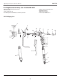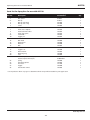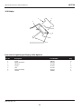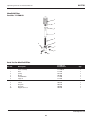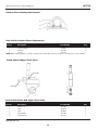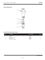
1
 Operating Instructions and Parts Manual
AL2710
Please read and save these instructions. Read carefully before attempting to assemble, install, operate or maintain the product described.
Protect yourself and others by observing all safety information. Failure to comply with instructions could result in personal injury and/or
property damage! Retain instructions for future reference.
BUILT TO LAST
Airless Paint
Systems
Thank you for purchasing a Campbell Hausfeld product. If you have any technical
questions about this product, please call 1-800-626-4401.
For Parts and Accessories: 1-800-626-4401
REMINDER: Keep your dated proof of purchase for warranty purposes! Attach it to this manual or file it for safekeeping.
© 2002 Campbell Hausfeld/Scott Fetzer
For parts, product & service information
visit www.chpower.com
IN422400AV 12/02
Operating Instructions and Parts Manual
AL2710
Airless Paint Systems
Table of Contents
Service . . . . . . . . . . . . . . . . . . . . . . . . . . . . . . . . . . . . . . . .
Spray Gun . . . . . . . . . . . . . . . . . . . . . . . . . . . . . . . . . .
Fluid Pump . . . . . . . . . . . . . . . . . . . . . . . . . . . . . . . . . .
Gear and Pump Assembly . . . . . . . . . . . . . . . . . . . . . .
Piston Rod, Upper Check Valve . . . . . . . . . . . . . . . . .
Lower Suction Valve . . . . . . . . . . . . . . . . . . . . . . . . . .
Maintenance . . . . . . . . . . . . . . . . . . . . . . . . . . . . . . . . . . .
Regular Maintenance . . . . . . . . . . . . . . . . . . . . . . . . .
Electric Motor Maintenance . . . . . . . . . . . . . . . . . . . .
V-Packing Replacement . . . . . . . . . . . . . . . . . . . . . . .
Troubleshooting Charts . . . . . . . . . . . . . . . . . . . . . . . . . .
Parts Diagrams . . . . . . . . . . . . . . . . . . . . . . . . . . . . . . . . .
Parts Lists . . . . . . . . . . . . . . . . . . . . . . . . . . . . . . . . . . . . .
Warranty . . . . . . . . . . . . . . . . . . . . . . . . . . . . . . . . . . . . . .
Description . . . . . . . . . . . . . . . . . . . . . . . . . . . . . . . . . . . . . 2
Specifications . . . . . . . . . . . . . . . . . . . . . . . . . . . . . . . . . . . 2
Safety Guidelines . . . . . . . . . . . . . . . . . . . . . . . . . . . . . . . . 2
General Safety Information . . . . . . . . . . . . . . . . . . . . . . . . 2
Pre-Operation . . . . . . . . . . . . . . . . . . . . . . . . . . . . . . . . . . . 4
Flushing . . . . . . . . . . . . . . . . . . . . . . . . . . . . . . . . . . . . . 4
Setting Up . . . . . . . . . . . . . . . . . . . . . . . . . . . . . . . . . . . 5
Spray Tip Selection . . . . . . . . . . . . . . . . . . . . . . . . . . . . 6
Operation . . . . . . . . . . . . . . . . . . . . . . . . . . . . . . . . . . . . . . 6
Starting Up . . . . . . . . . . . . . . . . . . . . . . . . . . . . . . . . . . 6
Spray Technique . . . . . . . . . . . . . . . . . . . . . . . . . . . . . . 8
Electrical System . . . . . . . . . . . . . . . . . . . . . . . . . . . . . . . . . 8
Electical Board Calibration . . . . . . . . . . . . . . . . . . . . . . 8
Electrical Troubleshooting . . . . . . . . . . . . . . . . . . . . . . 9
Replacement of Electrical Components . . . . . . . . . . . 10
Description
Safety Guidelines
Airless paint sprayers are capable of
spraying a wide variety of latex, oilbased, and alkyd paints, as well as
stains, preservatives and other nonabrasive finishes.
This manual contains information that
is very important to know and
understand. This information is
provided for SAFETY and to
PREVENT EQUIPMENT PROBLEMS. To
help recognize this information,
observe the following symbols.
These sprayers are also powerful and
versatile enough to be used with a
variety of options (roller attachment,
extra lengths of hose, etc.) to make it
an even more efficient tool.
NOTE: Guns pictured in illustrations
may be different than the one included
with your unit.
Danger indicates
an imminently
hazardous situation
which, if not avoided, will result in
death or serious injury.
!
DANGER
Warning indicates
! WARNING a potentially
Specifications
hazardous situation
which, if not avoided, could result in
death or serious injury.
Max. Pressure. . . . . . . . . . . . . . 3000 psi
Tip Size. . . . . . . . . . . 1 gun up to 0.023
Caution indicates a
potentially
hazardous situation
which, if not avoided, MAY result in
minor or moderate injury.
Motor Output. . . DC. TEFC. 1.3 HP Peak
Output (Free Flow). . . . . . . . . 0.8 GPM
Output (At Pressure). . . . . . . . 0.6 GPM
Weight . . . . . . . . . . . . . . . . . . . . . 65 lbs.
!
CAUTION Notice indicates
important
information, that if
not followed, may cause damage to
equipment.
NOTICE
www.chpower.com
2
10
10
11
11
12
12
12
12
12
12
14
16
23
28
Unpacking
After unpacking the unit, inspect
carefully for any damage that may
have occurred during transit. Make
sure to tighten fittings, bolts, etc.,
before putting unit into service.
Do not operate
! WARNING unit if damaged
during shipping,
handling or use. Damage may result in
bursting and cause injury or property
damage.
General Safety
Information
1. Read all manuals included with this
product carefully. Be thoroughly
familiar with the controls and the
proper use of the equipment.
2. Always wear a mask or respirator
and eye protection when painting.
Be certain mask or respirator will
provide necessary protection
against inhalation of harmful
vapors.
3. Keep visitors away and NEVER allow
children or pets in the work area.
Operating Instructions and Parts Manual
AL2710
Airless Paint Systems
General Safety
Information (Cont.)
4. Do not smoke or eat when spraying
paint, insecticides, or other
flammable substances.
5. Always work in a clean
environment. To avoid injury and
damage to the workpiece, do not
aim the spray gun at any dust or
debris.
6. When spraying and cleaning,
always follow the instructions and
safety precautions provided by the
material manufacturer (Refer to
MSDS).
!
DANGER
Electrical Shock Hazard:
● Follow all local electrical and safety
codes, as well as the National
Electrical Code (NEC) and in the
United States, the Occupational
Safety and Health Act (OSHA).
● This product requires a grounded
120V, 15 Amp circuit (See Figure 1).
● If the power receptacles available
Grounded
Outlet
TEST
Grounding Pin
Figure 1 - Grounding
RESET
Grounded Outlet
Box
will not fit this equipment’s power
cord, then have an appropriate
power receptacle installed by a
certified electrician.
● Only qualified electricians or
service personnel should perform
maintenance on the electrical
components of this equipment.
● If using an extension cord, use only
grounded three wire extension
cords that are in good condition. See
Table 1 on page 4 for information
on proper extension cord gauges.
● Do not modify any of the electrical
components of this
equipment.
● Do not use a power cord
adapter with this
equipment.
● Check with a qualified electrician or
service person if the grounding
instructions are not completely
understood or you are in doubt as
to whether the equipment is
properly grounded.
! WARNING
Skin Injection Hazard:
● High pressure spray can inject
toxins into blood
stream. If injection
occurs, seek
emergency medical
treatment.
! WARNING
Use a
face mask/respirator and
protective clothing when
spraying. Always spray in a
well ventilated area to prevent health
and fire hazards. Refer to Material
Safety Data Sheets (MSDS) of spray
material for details.
● Never try to stop leaks with any
part of your body.
● This system is capable of producing
3000 psi. Use only Campbell
Hausfeld replacement parts rated
at 3000 psi or higher.
● Never spray without tip guard.
● Ensure trigger lock is functioning
properly.
● Always engage trigger lock when
not spraying.
● Do not remove spray tip while
cleaning pump.
● Never leave equipment pressurized
while unattended.
PRESSURE RELIEF PROCEDURE
Before servicing or resting unit,
relieve pressure from system by
following this procedure:
1. Engage gun trigger lock.
2. Turn unit off and disconnect
power.
3. Disengage gun trigger lock.
4. Trigger gun
into
grounded
pail to relieve
pressure in
hose and
gun. While doing so, hold metal
part of gun in contact with pail.
Use the smallest amount of
pressure possible.
5. Turn Prime/
Pressure Relief
Valve (PR
Valve) to the
Wide Gap
open (priming) position to
relieve
pressure.
Slight Gap
NOTE: There
will be a wider gap between valve
handle and cam body when in
open position.
6. Engage gun trigger lock. Close
Prime/Pressure Relief Valve.
NOTE: If spray tip or hose is clogged,
follow step 1 to 5. If you suspect
pressure has not been relieved after
following this procedure, take your
unit to a Campbell Hausfeld Service
Center.
● Do not clean spray tip while it is
attached to the spray gun. Remove
spray tip from gun to clean tip
guard.
● Ensure tightness of high pressure
connections.
www.chpower.com
3
AL2710
Operating Instructions and Parts Manual
Airless Paint Systems
General Safety
Information (Cont.)
toxic chemicals,
fertilizers or pesticides. Using these
materials could result in death or
serious injury.
● Do not use pliers to tighten or
loosen high pressure connections.
● Motor is equipped with an automatic
thermal overload. Motor will restart
without warning, after cooling.
Do not spray acids,
! WARNING corrosive materials,
Never aim or
! WARNING spray at yourself
or anyone else or
serious injury could occur.
! WARNING
FIRE OR EXPLOSION HAZARD:
● Do not use solvents with flash
points less than 70°F (21°C) to clean
this equipment (examples of
acceptable cleaning solvents are
water, mineral spirits, lacquer
thinner, Xylene and high flash
napha. A partial example list of
unacceptable cleaning solvents are
low flash napha, mek, acetone,
alcohol and toluene).
! WARNING
Pre-Operation
FLUSHING
● Paints and solvents containing
HALOGENATED HYDROCARBONS can
react explosively with aluminum. Do
not use halogenated hydrocarbons
with this equipment. Consult the
paint or solvent product label or
Material Safety Data Sheets (MSDS)
to help determine if it contains
halogenated hydrocarbons.
● Do not use fuels to clean this
equipment.
● Keep spraying area well ventilated.
Keep doors and windows open.
● Remove all ignition sources (i.e.
Static electricity, pilot lights,
cigarettes and electrical arcing).
● Airless spraying can cause static
electricity. Always ground the
pump and spraying surface. Always
use a 3-wire grounded extension
cord and power receptacle.
● Do not use solvents containing
halogenated hydrocarbons.
Keep hose away
! CAUTION from sharp objects.
Do not
spray flammable materials
in vicinity of open flame or
near ignition sources.
Motors, electrical equipment and
controls can cause electrical arcs that
will ignite a flammable gas or vapor.
Never store flammable liquids or gases
in the vicinity of the unit.
secure.
1. New Sprayer: Your sprayer was
factory tested in an oil solution which
was left in the pump. Before using oilbased paint, flush with mineral spirits
only.Before using water-based paint
flush with mineral spirits, followed by
soapy water, then a clean water flush.
2. Changing Colors: Flush with a
compatible solvent such as mineral
spirits or water.
3. Changing from water-baseD to
oil-based paint: Flush with soapy
water, then mineral spirits.
4. Changing from oil-baseD to
water-baseD paint: Flush with
mineral spirits, followed by soapy
water, then a clean water flush.
5. Storage: Always relieve pressure
(See pressure relief procedure on
page 3) prior to storage or when
machine is unattended. Follow the
storage procedure based on the kind
of paint you used:
Bursting hoses may
cause injury. Examine hoses regularly
and replace if damaged.
● Oil-based paint: Flush with mineral
spirits. Make sure that there is no
pressure in the unit. Then close the
prime/pressure relief valve.
● Check hoses for weak or worn
condition before each use, making
certain that all connections are
● Water-based paint: Flush with
water, then mineral spirits. For
longer term storage use a 50/50
Extension Cord Requirements
Amperage
Rating
25
50
100
5-6
18
16
12
Length of Cord (Ft.)
150
200
250
12
10
10
300
400
500
8
8
6
6-8
18
16
12
10
10
8
6
6
6
8 - 10
18
14
12
10
8
8
6
6
4
10 - 12
16
14
10
8
8
6
6
4
4
Table 1 - Extension Cord Gauges
www.chpower.com
4
G
A
U
G
E
AL2710
Operating Instructions and Parts Manual
Airless Paint Systems
mixture of mineral spirits and motor
oil. Always ensure that there
Pre-Operation
counterclockwise to decrease it.
● Toggle Switch (Figure 4).
Procedure
(Cont.)
is no pressure in the unit, and close
the prime/pressure relief valve for
storage.
1. Make sure the gun trigger lock is
engaged and there is no spray tip in
the gun. Refer to Figure 5. (Refer to
Figure 10 for information on how
Never leave pump ! WARNING unattended while it
7. Turn the Prime/PR Valve to the
"CLOSED" position. This will allow
solvent to be flushed through the
pump, hoses and gun. Allow the
unit to operate until clean solvent
comes from the gun.
is under pressure!
6. Start up after storage: Before
using water-base paint, flush with
soapy water and then a clean water
flush. Before using oil-base paint,
flush out the mineral spirits with
the material
to be sprayed.
8. Release the trigger and engage the
gun trigger lock.
Figure 5 - Engaging trigger lock
HOW TO FLUSH
Important
Components
to lock the trigger lock and the
gun's safety features.)
Wide Gap
● Prime/Pressure
Relief Valve
(Prime/PR
Slight Gap
Valve, Figure
Figure 2 - PR Valve
2). Used to
relieve
pressure from gun, hose and tip
and to prime the unit when in
OPEN position. (It is in open
position when there is a wider gap
between valve handle and cam
body.) When in CLOSED position,
there is only a very slight gap
between
handle and
body. When
closed, the
system is
Figure 3 - Pressure
Control
pressurized.
● Pressure Control Knob (Figure 3).
Used to adjust pressure. Turn
clockwise to increase pressure and
ON
Figure 4 - Toggle Switch
OFF
6. Disengage the gun safety latch and
squeeze the gun trigger. Turn the
ON-OFF Toggle Switch to the "ON"
position (Figure 4) and turn
Pressure Control Knob (Figure 3)
clockwise to increase pressure just
enough to start the pump.
To reduce the risk ! WARNING of static sparking,
which can cause fire
or explosion, always hold a metal part
of the gun firmly against the grounded
pail when flushing. (This also reduces
splashing.)
2. Pour enough clean, compatible
solvent into a large, empty pail to
fill the pump and hoses.
3. Place the suction tube into the pail.
4. Turn the Prime/Pressure Relief (PR)
Valve to the "OPEN" , priming
position. Refer to Figure 3.
9. If you are going to start spraying,
place the suction tube into the
supply container. Release the gun
safety latch and trigger the gun
into another empty, metal
container, holding a metal part of
the gun firmly against the pail and
force the solvent from the pump
and hose. Engage the gun safety
latch until you are ready to spray.
10. If you are going to store the sprayer,
remove the suction tube from the
solvent pail, holding a metal part of
the gun firmly against the pail and
force the solvent from the pump and
hose. Engage the gun safety latch.
Refer to "Storage" Procedure on
page 4.
11.Whenever you shut off the sprayer,
follow the "PRESSURE RELIEF
PROCEDURE" on page 3.
SETTING UP
1. Connect the hose and gun.
Figure 6 - Holding gun against pail
a. Remove the plastic cap plug
from the outlet tee and screw a
conductive or grounded 3000 psi
airless spray hose onto fluid outlet.
5. Point the gun into the pail and hold
a metal part of the gun firmly
against the pail. Refer to Figure 6.
www.chpower.com
5
AL2710
Operating Instructions and Parts Manual
Airless Paint Systems
b. Connect an airless spray gun to
the other end of the hose.
Pre-Operation
(Cont.)
NOTE: Do not use thread sealer on
swivel unions as they are made to selfseal. Use thread seal on tapered male
threads only.
flow rate or capacity the sprayer can
accommodate. Pump flow rate is
measured in gallons per minute (GPM).
Pattern Width
Thickness of the paint coat is
determined by spray tip “fan width,”
rate of the spray gun movement, and
distance to surface.
Spray Tip Selection
Two tips having the same tip size, but
different pattern widths, will deliver
the same amount of paint over a
different area (wider or narrower
strip).
A spray tip with a narrow pattern
width makes it easy to spray in tight
places.
Figure 7 - Applying throat seal oil
2. Fill the Packing Nut/Wet Cup 1/3 full
with Throat Seal Oil (TSO) supplied
(see Figure 7).
3. Check the electrical service. Make
sure that the electrical service is 120
VAC, 15 amp minimum, and that
the outlet you are using is properly
grounded.
Make sure that all ! WARNING sprayer
components, work
pieces, spray material containers, and
electrical outlets are properly grounded
before operating unit.
4. Flush the sprayer according to the
Flushing section (New Sprayer) and
How to Flush section.
SPRAY TIP SELECTION
See Tip Selection Chart on Page 7.
Spray tip selection is based on paint
viscosity, paint type, and job needs. For
light viscosity (thin paints), use a
smaller tip. For heavier viscosities
(thicker paints), use a larger tip size.
Spray tip size is based on how many
gallons of paint per minute can be
sprayed through the tip. Do not use a
tip larger than the maximum pump
Spray Tip Replacement
During use, especially with latex paint,
high pressure will cause the orifice to
grow larger. This destroys the pattern.
Replace tips before they become
excessively worn. Worn tips waste
paint, cause overspray, make cutting-in
difficult, and decrease sprayer
performance.
Operation
To stop unit in an ! WARNING emergency, turn
motor off. Then
relieve fluid pressure in pump and hose
as instructed on page 3.
4. Prime the pump.
a. Allow pump to operate until
paint comes from gun.
b. Release the trigger and engage
the gun safety latch.
c. Turn Prime/PR Valve OPEN to the
prime position ensuring the
pressure is released from the
system.
d. Turn Pressure Control Knob to
minimum pressure.
e. Install spray tip onto gun.
f. Close the Prime/PR Valve to the
pressure position.
g. Turn the pressure control knob
to desired spray pressure.
h. Disengage the gun safety lock
and you are ready to start
spraying.
If spraying into the !
paint bucket, use
the lowest spray
pressure possible and maintain firm
metal-to-metal contact between gun
and container as shown in Figure 6.
CAUTION
5. Adjust pressure.
STARTING UP
1. Learn the functions of the controls
(See How to Flush section,
Important Controls).
2. Prepare the material according to
the material manufacturer’s
instructions. Place the suction tube
into the material container.
Make sure gun is !
pointed into empty
bucket at all times.
Never point gun toward people o r
animals. Avoid pointing toward dust
and debris. Avoid pointing toward
other objects .
WARNING
3. Start the sprayer as follows:
a. Prime/PR Valve must be
“OPEN” in the priming position.
b. Turn to the ON-OFF Toggle
Switch to the “ON” position.
www.chpower.com
6
a. Turn Pressure Control Knob
clockwise to increase pressure and
counterclockwise to decrease it.
b. Always use the lowest pressure
necessary to completely atomize
the material.
Operating the sprayer at higher
pressure than
necessary wastes material, causes early
tip wear, and shortens the life of the
sprayer.
NOTICE
c. If more coverage is needed, use
a larger spray tip rather than
increasing the pressure.
d. Check the spray
pattern. The tip
size and angle
determine the
AL2710
Operating Instructions and Parts Manual
Airless Paint Systems
pattern width and flow rate.
6. If spray tip is clogged, clean only
after removing it from the gun.
! WARNING
To reduce risk of spray injection, never
hold
Operation
(Cont.)
hand, body fingers or hand in front of
spray tip when cleaning or checking for
follow this procedure.
a cleared tip. Always point the gun
toward the ground or into an empty
container when checking to see if the
tip is cleared or when using a selfcleaning tip. Always remove tip before
cleaning.
a. Whenever you stop spraying,
even for a short break, follow the
Pressure Relief Procedure on page
3.
b. Clean the tip and gun as
recommended by your separate
gun instruction manual.
NOTE: When pausing during a paint
job, keep tip clean by locking the gun
and submerging the tip in a small
bucket of paint thinner. This will help
reduce buildup and drying of paint in
tip, tip guard, and gun.
c. Flush the sprayer at the end of
each work day if the material you
are spraying is waterbased, or if it
could harden in the sprayer
7. When shutting off the sprayer,
Tip Selection Chart
QuadraflowTM Tip
Fan Width (in.)
4-6
6-8
8-10
10-12
12-14
14-16
16-18
Gun Filter
for painting
(12" from surface)
(mm)
102-152
152-203
203-254
254-305
305-356
356-406
406-457
2 types (part #)
Lacquer, Varnish
Wood Interior
Stain, Sealer
Orifice Size (inches)
.009
.011
.013
Masonry
.017
.019
AL2213
AL3122 AL3125
AL3126
AL3118
AL3120
AL2215 AL2217
AL3130
AL3132 AL3135 AL3137
AL3139
AL3121
AL3124 AL3127
AL2219
AL2221 AL3136 AL3138
AL3140
AL3131
AL3134
l---------AL086101AJ------l
l--------------AL086100AJ---------------l
Vinyl, Oil Base Alkyd
Latex, Acrylic
Block Filler
Elastomer
(gpm)
.12
REMOVE FILTER
Vinyl, Acrylic, Latex
Water Flow Rate
.029
.025 .027 .031 .035
AL3119
Hi Build, Mil White
Heavy Coatings
.023
AL2211
Exterior Stain
Ceiling
Structural Steel
.021
AL3116 AL3117
Enamel
Wood Exterior
.015
.18
.24
.31
.38
.47
.57
.67
.77
1.03
1.31
2.15
2.54 2.96 3.90
4.98
(water @ 2000psi,
138 bar)
(lpm)
.49
.69
.91
Paint Flow Rate
(gpm)
.10
.15
.21
.27
.33
.40
.49
.58
.88
1.12
(latex paint @ 2000psi, 138
bar/1.36 spec. gr.)
(lpm)
.38
.57
.79
1.02
1.25
1.51
1.85
2.20 2.50 3.33
4.24
(gpm)
.25
.25
.33
.40
.50
.60
.75
.88
1.00 1.25
1.50
(lpm)
1.00
1.00
1.25
1.50
1.90
2.30
2.80
3.30 3.80 4.70
5.70
Pump Minimum
Output*
1.17
1.47
1.79
.66
*pump will support tip worn to next larger size.
Consult your paint manufacturer for application recommendation
Table 2 - Tip Selection Chart
www.chpower.com
7
Operating Instructions and Parts Manual
AL2710
Airless Paint Systems
overnight. See "Flushing" page 4.
Use a compatible solvent to flush,
then fill the pump and hoses with
an oil based sovent such as mineral
spirits.
d. For long term shutdown or
storage, refer to page 4.
Be sure to relieve ! WARNING pressure in the
pump after filling
with mineral spirits.
Operation
(Cont.)
SPRAY TECHNIQUE
Good Spray Gun Technique is at the
core of any spray paint operation.
Operator skill and efficiency is as
important as good equipment and
good paint. Good spray technique is a
skill that can be developed by
following these simple instructions.
If you are not familiar with spraying
techniques, study this section of your
manual and practice the proper
technique on pieces of cardboard or a
suitable surface.
Hold the spray gun 12 - 15 inches away
from the work surface and keep it
perpendicular (straight) to the surface.
Move the spray gun parallel to the
work and at a right angle to the
surface. (See Figure 8).
Move the gun at a steady rate in order
to apply a good coverage. The wet
coat should be just under the thickness
at which a run or sag will occur. Slow
gun movement or gun held too close
will result in an overly wet or thick wet
or thick coat coverage that is likely to
run or sag.
INCORRECT
Do not wave the spray gun. This
waving is called arching. Instead, hold
the spray gun at a 12 to 15 inch
distance perpendicular from the work.
(See Figure 9.)
The closer the spray gun is held to the
work, the thicker the paint is deposited
and the faster the gun must be moved
to prevent sags and runs. Holding the
gun too far from the work will cause
excessive fog, overspray, and a thin and
grainy coat.
It is important to "trigger" the gun
after gun movement (arm movement)
has started and release trigger (shut
gun off) before gun movement ends.
Gun movement is always longer than
actual paint (spray) stroke. In that
manner, even blending and uniform
paint coat thickness is achieved over
the entire surface. When the gun is in
motion as the trigger is pulled, it
deposits an even amount of paint.
Overlap the previous pass by half the
RIGHT
Release End
Trigger
CORRECT
Figure 9 - Proper Spray Technique
width of the spray pattern. Aim at the
bottom of the previous pass.
Adjust Pressure Control Knob so that
paint is completely atomized from the
spray gun. Insufficient pressure will
result in “tailing.” Too much pressure
will result in excess fog and overspray,
excessive tip wear, and increased
sprayer wear and tear.
Always use the lowest pressure possible
to obtain desirable results. Test the
spray pattern on a piece of cardboard
or other surface.
To cover “inside” and “outside”
corners (on walls or other objects), aim
the spray gun toward the center of the
corner. The spray pattern is divided in
half, and the edges of the spray
pattern on both walls are the same.
12-15”
Gun is held perpendicular
to work piece, fluid
disperses evenly
Start Pull
Trigger
Gun is held at an angle,
fluid disperses unevenly
WRONG
Figure 8 - How to hold spray gun when spraying
www.chpower.com
8
Electrical System
ELECTRICAL BOARD CALIBRATION
NOTE: Anytime a sensor, pressure
control assembly (board) or both are
replaced, the following calibrations
must be performed.
AL2710
Operating Instructions and Parts Manual
Airless Paint Systems
Zero Calibration
1. Place prime/pressure relief valve in
the prime (open) position.
2. Set the pressure control knob to the
minimum setting (CCW).
3. Remove the screws and lower the
pressure control assembly.
calibration, the sensor is defective and
should be replaced.
8. IMPORTANT: When calibration is
complete, move jumper from both
"PZ-R" terminals to single terminal
on P-ZR.
Pressure Calibration
4. Ensure the jumper is on the "P-ZR"
terminal. Note: This jumper comes
with a new pressure control
1. Complete the ZERO calibration, as
per "ZERO CALIBRATION" prior to
commencing this calibration.
Electrical System
2. Attach a 50', 1/4" airless hose,
airless gun with 0.017 tip and a
5000 psi glycerin filled pressure
gauge to the pump.
(Cont.)
assembly (board) and is installed on
the "P-ZR" terminals. If you are
"Zero Calibrating" a pressure
control assembly presently in the
unit, remove jumper from single
terminal P-ZR and place on both
terminals P-ZR. When Zero
Calibration is complete, replace
jumper on a single terminal of P-ZR.
5. Turn machine "ON" and ensure it is
not cycling.
6. If the yellow zero light on the
electrical board is ON, use an
insulated screwdriver to turn the
"ZERO" trimpot counterclockwise
until the light goes out. Then turn
it clockwise until the light just
comes back on. If so equipped, look
at the LCD Display and if "0000" is
showing the Zero Calibration is
complete. If the display shows more
than "0000", turn the Zero Trimpot
CCW until "0000" is showing. If
"-- -- --" is showing, turn the zero
trimpot CW until "0000" is
displayed.
7. If the yellow light is OFF, turn the
"Zero" trimpot clockwise, just until
the light comes on and stop.
Confirm "0000" is displayed.
NOTE: If the yellow light remains
constantly "ON" or "OFF" during this
3. Place the suction tube into a bucket
of Coro-chek and water.
4. Turn Prime/Pressure Relief Valve to
the prime (open) position.
5. Turn Pressure Control Knob
clockwise until machine starts to
prime.
6. Place the Prime/Pressure Relief
Valve in the pressure (closed)
position.
7. While watching pressure gauge,
slowly adjust the pressure trimpot
(clockwise to increase and
counterclockwise to decrease) until
the maximum static pressure is 3000
psi, with the pressure control knob
fully clockwise. Trigger the gun into
pail several times to ensure pressure
returns to 3000 psi.
Liquid Crystal Display (LCD)
Calibration
NOTE: Your unit may or may not be
equipped with an LCD.
1. Complete the "ZERO CALIBRATION"
and "PRESSURE CALIBRATION"
procedures prior to starting this
calibration.
2. Turn Pressure Control Knob up until
system pressure is above 2500 psi
(as indicated on glycerin filled
pressure gauge) and the machine is
not cycling.
3. Use an insulated screwdriver to
adjust the Set trimpot. Turn trimpot
counterclockwise until it clicks, and
then adjust to match pressure
against pressure gauge reading.
4. Move the pressure control knob to
different settings and trigger the
gun several times into pail. This will
ensure that the LCD continues to
match the pressure gauge reading.
Phase Limit Trimpot Calibration
(formerly known as the Low Voltage or
Master Voltage Calibration)
1. Attach a 50', 1/4" airless hose,
airless gun with .017 tip and a 5000
psi glycerin filled pressure gauge to
the pump.
2. Place the suction tube into a bucket
of Pump Conditioner and water.
3. Turn pump ON and turn up Pressure
Control until the machine starts to
prime.
4. Place the Prime/Pressure Relief
Valve in the pressure (closed)
position.
5. Pressurize pump to 600 psi.
6. Trigger the gun several times
noting the deadband (the amount
of pressure drop before the pump
rebuilds to set pressure).
7. If deadband is greater than 100 psi,
adjust the low pressure voltage
trimpot so that the deadband is less
than 100 psi and the pressure
increase after the gun trigger is
released is less than 200 psi. These pressures are guidelines and
may vary slightly from pump to
pump.
8. Reattach Pressure Control Assembly
being careful not to pinch wires.
NOTE: The 331-315-99 Pressure Control
Assembly has a reddish brown terminal
www.chpower.com
9
Operating Instructions and Parts Manual
AL2710
Airless Paint Systems
labelled “Inhibit Switch.” At all times
there should be a jumper on the two
left terminals, which are the closest to
the “S2” connection. Also on the
Revision E is a terminal labelled “ONSL.” This terminal should never have a
jumper on it.
ELECTRICAL TROUBLESHOOTING
A variety of causes can lead to
problems with your sprayer’s electrical
system. Sometimes, it will not start. See
page 15 for a list of possible problems
and solutions to fix them.
Electrical System
(Cont.)
REPLACEMENT OF ELECTRICAL
COMPONENTS
NOTE: Refer to Electrical System
Diagram (page 20) and LCD Diagram
(page 22).
Pressure Control Assembly
(Electrical Control Board)
2. Disconnect potentiometer lead
from pressure control assembly.
3. Use a 1/16" allen wrench, loosen set
screw in the potentiometer knob
and remove knob and spacer.
4. Using a 1/2" wrench or deep socket,
remove the nut from the
potentiometer shaft assembly.
5. Pull entire potentiometer assembly
out of terminal box.
6. Replace in reverse order.
Liquid Crystal Display (LCD)
5. Reassemble in reverse order.
2. Unscrew the four nuts (6/32") and
remove LCD Display assembly.
Service
3. If unable to loosen the four nuts,
hold them and unscrew the four
screws. Then remove the LCD
Display Assembly. If the display is
removed in this manner, the mylar
label must be replaced.
3. Disconnect all leads from pressure
control assembly.
4. Reassemble in reverse order.
On-Off Toggle Switch
Sensor
1. Lower the pressure control
assembly as described above.
2. Remove four screws from pressure
control assembly.
1. Remove the screws and lower the
pressure control assembly.
2. Disconnect swivel from sensor by
holding sensor with 7/8" wrench
and loosening swivel with 11/16"
wrench.
3. Disconnect sensor lead from the
board. Carefully pull sensor lead
out of the terminal box and remove
sensor.
4. Reassemble in reverse order.
Potentiometer
1. Lower pressure control assembly as
described above.
nut from the holder shaft.
1. Lower pressure control assembly as
described above.
4. Reassemble in reverse order, while
making sure that the four spacers
and the four washers are in place.
Tighten the four nuts handtight
and seal with blue loctite. DO NOT
overtighten the nuts as this will
damage the display.
1. Unplug machine's power cord.
Figure 10 - Setting Trigger Lock
2. Disconnect the two wires on the
switch.
SPRAY GUN
Prior to servicing gun: Attach spray
gun to hose and tighten fittings
securely. Set the gun trigger lock. The
gun trigger lock should always be set
when the gun is not being triggered
(see Figure 10).
Hold gun with trigger locked and push
trigger against the lock . Then adjust
nut so that the retainer will move
freely back and forth approximately
1/32" to allow valve spring unit to seat
the valve ball.
IMPORTANT: Readjust nut periodically
for wear of valve seat and valve ball.
Otherwise, leakage will occur.
Replacing Valve Ball Holder
Kit #2-007
3. Use a 9/16" wrench to loosen the
nut on the toggle switch shaft.
Parts Needed: 3 Tip Washers, 1 Valve
Seat, 1 Valve Ball Holder, 2 Seals-PTFE
4. Reassemble in reverse order.
Dismantling:
Fuse Holder
1. Unscrew rev guard and remove spray
tip and seal.
1. Lower pressure control assembly as
described above.
2. Disconnect the two wires on the
holder.
3. Remove holder cover and fuse.
4. Use 11/16" wrench to remove the
www.chpower.com
10
2. Unscrew valve seat with 1/2" socket
wrench.
When removing and
replacing valve
seat, hold the trigger
in the open position so that the valve
ball is lifted off the valve seat. Failure
NOTICE
Operating Instructions and Parts Manual
AL2710
Airless Paint Systems
to life the ball off the seat will result in
a scrathed, leaky valve.
3. Unscrew valve ball together with the
brass part of the assembly. Do not pull
on the parts or the packing may get
damaged.
4. Unscrew the valve ball from the
brass part of the assembly.
Reassembling is done in reverse
sequence. Screw the new valve ball
with holder into the brass part.
Tighten valve ball and brass part on
threaded end of the
shaft by hand until you feel a positive
stop. Do not tighten
NOTICE
Service
(Cont.)
with a wrench since this could result in
breaking the shaft.
NOTE: It is recommended that you
change the valve seat and valve ball at
the same time.
Replacing Valve Spring Unit
Kit #3-007
Parts Needed: 3 Tip Washers, 1 Valve
Seat, 1 Valve Ball Holder, 1 Valve Spring
Unit
1. Repeat dismantling procedure as
outlined above under Steps 1
through 3.
2. Unscrew nut, remove retainer with
retainer pins and push shaft of the
valve spring unit out of the gun
head.
Install retainer pins, retainer, and nut
loosely onto valve spring unit. By hand,
turn front of valve spring unit
clockwise, tightening the valve spring
unit until you feel a positive stop. At
that point, continue tightening the
valve spring another 1/8 turn,
expanding the PTFE seals against body
of gun.
Do not tighten valve spring beyond
1/8 turn, as doing so
can break the valve spring unit shaft.
Continue reassembly and adjustment as
described above.
NOTICE
FLUID PUMP
NOTE: Check the Troubleshooting
Chart on page 14 before disassembling
the Fluid Pump.
Fluid Pump Disconnect
1. Flush out the material you are
spraying, if possible.
2. Follow the "Pressure Relief
Procedure" on page 3.
3. Remove the suction tube assembly
from the paint pump by unscrewing
the suction nut. Disconnect sensor
assembly by holding sensor with
7/8" wrench and unscrewing swivel
connector with an 11/16" wrench.
4. Move the piston rod to its lowest
stroke position by rotating the
motor fan or by cycling rod to
lowest position.
5. Unscrew the two screw from cover
assembly.
3. Clean gun head bore with solvent
and small brush. Do not use any
sharp objects to scrape away dried
paint, as they would cause leakage
around the seal.
6. Remove retaining ring. Slide sleeve
down off crosshead assembly
Remove pin out of crosshead
allowing removal of fluid pump
from unit.
Reassembling is done in reverse
sequence.
Fluid Pump Reinstallation
IMPORTANT: When reassembling,
install valve spring unit with spring
loose.
1. Loosen packing nut and extend
piston rod to its upper position in
paint pump. Slip sleeve and
retaining ring over piston rod.
Push firmly into gun head by hand.
2. Push piston rod up into crosshead
assembly and align holes. Insert pin
through crosshead assembly and
piston. Slip sleeve up over pin and
insert retaining spring into groove
on crosshead assembly.
3. Secure paint pump to cover
assembly by two screws, up through
tube spacers and screw into cover
assembly.
4. Tighten screws evenly and
alternating to 20 ft. lbs.
5. Reassemble the Lower Check Valve
assembly by placing the Suction
Seat Assembly, O-ring, ball and
retainer in the suction nut and
screw nut onto pump body.
6. Reconnect sensor assembly to fluid
pump. Hold sensor with 7/8"
wrench while tightening swivel
connector.
7. Start the pump and operate slowly
to check the Piston Rod for binding.
Adjust screws holding pump
assembly to cover assembly if
necessary to eliminate binding.
8. Tighten the packing nut until
resistance is felt against the
belleville springs, then 1/2 turn
more CW (approximately three
threads showing). Fill the wet cup
of Packing Nut 1/3 full of Throat
Seal Oil (TSO).
9. Run unit at full pressure for several
minutes, release pressure and
repeat step 4. Readjust packing nut
according to paragraph above.
GEAR AND PUMP ASSEMBLY
Do not operate ! WARNING machine without
cover guard in place.
1. Disconnect Fluid Pump as instructed
in Fluid Pump Disconnect.
2. Place piston in block (Tool Part No.
331-195) with the 3/8" dowel pin
(Tool Part No. 331-196) and hold in
vise. See diagram on page 21.
NOTE: DO NOT use smaller diameter pin
than Part No. 331-196 to hold piston.
www.chpower.com
11
AL2710
Operating Instructions and Parts Manual
Airless Paint Systems
3. Place a 1/4" allen wrench into
bottom of piston. Unscrew retainer
from piston. Clean all parts and
inspect them carefully for wear and
damage. Inspect the surface of
piston and seat for wear or
damage. Replace these parts if
needed. If repacking pump, replace
ball and O-ring with new parts from
Packing Kit.
4. Lay unit on its back and disassemble
gearbox.
5. Inspect bearings and Crosshead
Assembly Gearcrank and sleeve
bearing inside cover assembly for
wear or damage.
Service (Cont.)
Replace worn or damaged parts.
6. If gear grease needs replacing,
replace with gear grease (Part No.
331-132)
7. Clean mating surfaces of cover and
box thoroughly.stick Seal the
mating surfaces with gasket sealer.
8. Reassemble in reverse order.
PISTON ROD, UPPER CHECK VALVE
1. Disconnect fluid pump as shown on
page 11.
2. Place piston in block (Tool PN 331195) with the 3/8” dowel pin (Tool
PN 331-196).
NOTE: Do NOT use smaller diameter
pin than PN 331-196 to hold piston.
3. Place a 1/4” allen wrench into
bottom of piston. Unscrew retainer
from piston. Clean all parts and
inspect them for wear and damage.
Inspect the surface of piston and
seat for wear or damage.
4. To disassemble the piston assembly,
place in block using dowel pin and
hold in vise. Install ball, seat and
O-ring in this order. Use blue loctite
242 on retainer and screw into
piston. Tighten to 20 ft. lbs.
LOWER SUCTION VALVE
1. Unthread suction nut and remove
suction assembly from pump body.
2. Remove sxuction seat assembly,
O-ring, ball and retainer.
3. Clean all parts and inspect them for
wear or damage, replacing parts as
needed.
4. If lower seat needs replacing, you
can replace the suction seat
assembly (PN 331-292).
5. Clean inside of pump body.
6. If no further pump service is
needed, reassemble the lower check
valve assembly, O-ring, ball and
retainer in the suction nut and
screw nut onto pump body. Tighten
suction nut with rod tool.
Maintenance
REGULAR MAINTENANCE
1. Keep the displacement pump
packing nut/wet cup 1/3 full of TSO
(Throat Seal Oil) at all times. The
TSO helps protect the packings and
rod.
2. Inspect the packing nut daily.
Your pump has a patented Triple
Life Packing System. Packing life
will be extended a minimum of
three times if the following
"Packing Tightening" procedure is
followed:
2. Motor Brushes: These need
periodic inspection and replacement
according to wear. Brush wear is
influenced by individual application.
It is recommended that brush wear
be checked at early intervals of
operation. This will help determine
when inspections will be needed in
the future. Standard Leeson brushes
for this motor have an initial length
of 3/4”. When the brushes are worn
to a length of 3/8”, they should be
replaced.
3. Changing Brushes: Follow these
instructions:
a. Unplug machine.
b. Open the two covers at the rear
of motor.
c. Loosen the screw holding the
brush terminal and remove the
brush lead.
d. Push the brush retainer clip in
and remove.
e. Remove the worn brushes (one
on each side of motor).
f. Install new brushes in reverse
order and replace covers.
Inspect packing nut. (Do NOT spray
while inspecting.) If seepage of paint
into the packing nut and/or movement
of the piston upward is found, the
packing nut should be tightened
enough to stop leakage. Do not
overtighten, as this will damage the
packings and reduce the packing life.
NOTE: For longer life, new brushes
(Part No. 331-131) need to have a “runin” period. After changing brushes, set
up the machine for spraying. Use a
bucket of water and Coro-chek
mixture, a 50 ft x 1/4” airless hose, and
airless spray gun with 0.017 tip on unit.
Turn the Prime/PR Control Valve to the
prime position and turn unit on. Turn
Pressure Control Knob to maximum
pressure (fully clockwise position). Let
the pump cycle at high speed in the
prime position for 20 minutes. This will
allow the brushes to “run in” properly
and increase the life of the brushes.
ELECTRIC MOTOR MAINTENANCE
V-PACKING REPLACEMENT
1. Lubrication: This motor is supplied
with prelubricated ball bearings,
lubricated for life of bearing.
Disassembly
www.chpower.com
12
1. Remove the Fluid Pump as per
"Fluid Pump Disconnect"
AL2710
Operating Instructions and Parts Manual
Airless Paint Systems
3. Disassemble and clean all parts for
reassembly. Discard old packings,
adapters and O-Rings.
b. Five V-Packings, "V" inverted.
c. Female adaptor.
d. FiveV-Packing, "V" up.
e. Male Adaptor.
f. Slide on tube spacer.
g. Three Belleville Springs starting
with the first spring facing down
(
), second one facing up (
),
and the third one facing
down (
).
(
2. Unscrew the packing nut and
suction assembly. Push piston rod
out through bottom of pump body.
Remove the upper packings,
belleville springs, tube spacer and
lower packing set using packing
removal tool (PN 331-153).
a. Start with lower male adapter.
)
instructions on page 11.
h. Upper male adaptor.
NOTE: Do not use smaller diameter pin
to hold piston.
j. Place O-rings onto seal holder.
Maintenance
(Cont.)
5. Place a 1/4” allen wrench into insert
and unscrew insert from piston.
Clean piston and seat, and then
inspect them carefully for wear and
damage. Replace these parts if
needed.
Reassembly
1. To reassemble the piston assembly,
place in block using dowel pin and
hold in vise. Install ball, seat and
O-Ring in this order. Use blue loctite
242 on retainer and screw into
piston. Tighten to 20 ft. lbs.
Note: For pumps manufactured prior
to Year 2000 Install, Piston Rod
Assembly PN 331-093 Only. Assembly
PN 331-093 includes all new valve parts
that will update the old pumps to
present design.
)
4. Place piston in block (PN 331-195)
with the 3/8"dowel pin (PN 331196) and hold in vise.
i. Five V-Packings, "V" inverted.
k. Lubricate outside diameter of
V-packings with white lithium or
multipurpose grease.
l. Slide seal holder (2) over Upper
Packing Set.
m. Lubricate threads on inside of
pump body with white lithium or
Multipurpose grease.
5. Hold pump body in one hand
upside down and slide entire piston
assembly with packings up into
pump body, while rotating piston
and packing assembly.
6. Install packing nut, handtight only.
Push piston rod up to its upper
position.
7. Connect the fluid pump onto Unit
as per "Fluid Pump Reinstall"
Procedures on page 11.
2. Lubricate piston rod with oil or
multi-purpose grease.
3. Soak leather packings in throat seal
oil or other light-weight oil for
10-15 minutes.
4. Reassemble all parts onto piston
rod in following order (see page 24
for picture):
www.chpower.com
13
Operating Instructions and Parts Manual
AL2710
Airless Paint Systems
Troubleshooting Chart
Symptom
Unit does not prime
Unit primes, but has no
pressure or poor pressure
Unit does not maintain
good spraying pressure
Unit does not run
Possible Cause(s)
Corrective Action
1. Air leak due to:
a. Loose suction nut.
b. Worn O-rings.
c. Hole in suction hose.
2. Stuck or faulty balls.
a. Tighten suction nut.
b. Replace O-ring (PN 106-011) on suction seat.
c. Replace suction hose.
1. Service lower and upper check valves.
1. Pressure set too low.
2. Filters are clogged.
1. Turn up pressure.
2. Clean or replace gun filter, inlet filter and/or manifold
filter.
3. Upper check valve faulty or
worn.
3. Service upper check valve.
4. Prime/Pressure Relief Valve
bypassing.
4. Clean or replace Prime/Pressure Relief Valve.
5. Packings and/or piston worn.
5a. Tighten packing nut.
b. Repack unit.
1. Blown spray tip.
2. Packings and/or piston worn.
1. Replace spray tip.
2. Repack unit.
3. Upper seat worn.
3. Replace upper seat.
1. Blown fuse.
1. Replace fuse (20A SlowBlow).
2. Electrical failure.
2. See electrical troubleshooting on page 15.
www.chpower.com
14
AL2710
Operating Instructions and Parts Manual
Airless Paint Systems
Electrical Troubleshooting
If your machine will not start, follow these guidelines to help determine a cause and find a possible solution.
Possible Cause
Control Settings
Fuse
Power Source
Thermal Overload
Pressure Control Assembly
(Board)
Motor
Sensor
Pressure Control Knob
(Potentiometer)
Pressure Control Assembly
(Board)
Corrective Action
STEP 1: Ensure that the on-off toggle switch is in the “ON” position and that the
Pressure Control Knob is fully counterclockwise (maximum pressure). Also check that
the unit is plugged in.
STEP 2: Test the fuse for continuity or replace with a new fuse. If fuse is good, go to
Step 3.
STEP 3: Remove screws and lower the pressure control assembly and check to see if
the red power light on the board is lit. If the light is “OFF,” proceed to Step 4. If the
light is “ON,” go to Step 7.
STEP 4: Use a multimeter to check for 110 volts VAC across the L1 AND L2 terminals
on the board. If there is no voltage at these leads, there is no power to the unit.
Check power source (outlet, breakers, extension cord and power cord). If there is
voltage on L1 and L2, go to Step 5.
STEP 5: Disconnect the two red motor leads (S1 and S2) and test for continuity
between the two leads. Continuity shows that the motor's thermal coupler has not
tripped. No continuity means that the thermal coupler has opened due to excessive
motor heat. If the motor is still hot to touch, allow to cool and retest. If the motor is
cool and there is no continuity on the red leads, contact the nearest Campbell
Hausfeld Service Center to repair or replace the thermal coupler.
STEP 6: If all checks out fine in Steps 1 through 5 and the red light is still out, the
pressure control assembly is defective and must be replaced.
STEP 7: Remove motor Brush Covers. Turn unit on with Pressure Control Knob fully
clockwise to max. pressure position. Check for DC voltage across both brush
terminals. If you have greater than 80 VDC turn unit off and unplug. Ensure that the
brushes are evenly worn and make solid contact with motor commutator. Replace
the brushes if they are less than 3/8" long. If the brushes are okay, replace the motor.
If you do not have DC voltage at the brush terminals go to Step 8.
STEP 8: If the redlight is "ON", the power source, fuse, on/off switch and thermal
coupler are okay. Plug another sensor into board. If the unit starts, the sensor was
faulty and must be replace. When a replacement sensor is not available, use a
multimeter to test the resistance between the BLACK and RED wires on the sensor
lead. The resistance should be approximately 1.5 - 3.5 kohms. A faulty sensor usually
reads no continuity (open). Conduct the Zero calibration procedure. If unit cannot
be zero calibrated, that ensures sensor is bad. If sensor check is good, go to Step 9.
STEP 9: With the machine still "OFF", remove the potentiometer lead from the
board and read the resistance between the red and black wires. This must be 8 - 12
kohms. If outside this range, replace the potentiometer. NOTE: A bad POT usually
show no continuity (open).
STEP 10: If you do not have DC voltage at the motor brushes and all components
check good in Steps 8 and 9, the Pressure Control Assembly needs to be replaced.
www.chpower.com
15
AL2710
Operating Instructions and Parts Manual
For Replacement Parts, Call 1-800-626-4401
Please provide following information:
-Model number
-Serial number (if any)
-Part descriptions and number as shown in parts list
Address parts correspondence to:
Campbell Hausfeld
100 Production Drive
Harrison, OH 45030 U.S.A.
AL2710 Spray Gun
2
6
3
10
5
11
12
13
9a
4
1
9
7
16
17
18
19
20
21
25
22
26
23
24
www.chpower.com
16
14
15
AL2710
Operating Instructions and Parts Manual
Parts List for Spray Gun for use with AL2710
Ref. No.
Description
AL2710 Spray Gun
Part Number
1
2*
3
4
5
6
7
8
9
9a
10
11
12
13
14
15
16
17
18
19
20
21
22
23
24
25
26
AL2245
AL22xx
561-025
561-026
120-023
120-005
120-035
120-037
120-011
120-033
120-022
120-046
120-002
120-045
120-020
120-021
120-056
120-048
120-055
120-049
120-082
AL086100AJ
AL086101AJ
120-088
120-087
115-019
120-044
120-085
Rev-guard
Rev-tip
Rev-tip seal-metal
Rev-tip seal-o-ring
Screw
Guard
Valve seat complete
Valve ball with holder
Valve spring unit
Seals-PTFE
Trigger pin
Washer Gun head
Retainer pin
Retainer
Nut
Washer
Trigger lock
Wave washer
Retaining ring
Seal
Filter-Complete-Coarse (2 pk.)
Filter-Complete-Fine (2 pk.)
Spring
Handle-Complete
Connector
Trigger
Handle with swivel
Qty.
1
1
1
1
3
1
1
1
1
2
1
2
1
2
1
1
1
1
1
1
1
1
1
1
1
1
1
1
* See Tip Selection Chart on page 7 to determine which rev-tip will be needed for paint application.
www.chpower.com
17
AL2710
Operating Instructions and Parts Manual
Airless Paint Sprayer
Model AL2710
4
5
3
2
18
1
6, 7,
8, & 9
21
23
22
11
20
33
24
15 16 17 19
27
25
14
28
10
29
30
12
31
32
13
www.chpower.com
18
AL2710
Operating Instructions and Parts Manual
Parts List for Airless Paint Sprayer, Model AL2710
Ref. No.
Description
AL2710 Airless Paint Sprayer
Part Number
1
Pail hook
331-336
2
Screw
100-390
3
Cover
331-234
4
Frame
331-273
5
Motor cover
331-199
6
0.8 HPDC Motor
331-068
7
Motor fan
331-212
8
Fan cover
331-213
9
Fan cover screws
117-090
10
Tire
113-017
11
Not applicable
12
Collar
143-029
13
Rubber boot
331-048
14
Prime/PR Valve
100-180
15
Swivel
100-003
16
Sensor
331-294-99
17
Sensor seal
106-500
18
Rubber edge
331-337
19
Pressure assembly
331-315-99
20
Screw
110-037
21
Screw
100-377
22
Terminal box
331-321
23
Knob
117-044
24
Washer
331-103
25
Screw
100-312
26
Motor brush
331-398
27
Suction nut
331-034
28
Suction seat assembly
331-292
29
Bypass hose
331-424
30
Spring clip
331-135
31
Inlet tube
331-400
32
Filter
141-008
33
Fitting
331-090R
NOTE: Specify quantity needed when ordering. Otherwise only one (1) quantity will be shipped.
Qty.
1
2
1
1
1
1
1
1
1
2
2
2
1
1
1
1
2
1
4
4
1
1
4
4
2
1
1
1
1
1
1
1
www.chpower.com
19
AL2710
Operating Instructions and Parts Manual
Electrical System
www.chpower.com
20
AL2710
Operating Instructions and Parts Manual
Parts List for Electrical System
Ref. No.
Description
Part Number
331-168
331-185
331-138
331-311
331-328
331-312
331-068
331-315-99
117-207
331-294-99
331-297
331-184
117-044
331-377
1
2
3
4
5
6
7
8
9
10
11
12
13
14
Electrical power cord
Strain relief
Screw
Toggle switch
Fuse 20A Slow Blow
Fuse holder
0.8 HP DC motor
Pressure control assembly
Jumper
Sensor
Potentiometer
Spacer
Knob
LCD-Optional Display
Qty.
1
1
1
1
1
1
1
1
1
1
1
1
1
1
www.chpower.com
21
AL2710
Operating Instructions and Parts Manual
LCD Display
1
2
7
3
4
5
6
Parts List for Liquid Crystal Display (LCD)-Optional
Ref. No.
Description
Part Number
100-362
101-270
331-360
117-281
117-126
331-377
120-046
1
2
3
4
5
6
7
Screw
Mylar Label-Clear
Window
Spacer
Nut
Display Assembly
Washer
www.chpower.com
22
Qty.
4
1
1
4
4
1
4
AL2710
Operating Instructions and Parts Manual
Manifold Filter
Part No. 111-200-99
1
2
3
4
5
6
8
7
8
9
10
Parts List for Manifold Filter
Ref. No.
Description
111-200-99
Part Number
111-200-99
111-202
301-356
106-007
111-204
111-203
111-201
100-101
100-129
100-028
100-109
-
1
2
3
4
5
6
7
8
9
10
Filter assembly
Base
Spring
O-ring
Filter-60 Mesh
Support
Base
Swivel
Plug 3/8”
Plug 1/4”
Nipple 3/8 x 1/4
Qty.
1
1
1
1
1
1
1
1
2
1
1
www.chpower.com
23
AL2710
Operating Instructions and Parts Manual
Gearbox Sleeve Bearing Replacement
1
2
3
Parts List for Gearbox Sleeve Replacement
Ref. No.
Description
Part Number
Qty.
1
Sleeve bearing
331-061
1
2
Washers
331-103
2
3
Screws
331-197
2
NOTE: When replacing item 1, cover the outside of the sleeve with clear silicone prior to inserting into cover assembly.
Piston Rod and Upper Check Valve
331-195
1
331-196
2
3
4
5
Parts List for Piston Rod, Upper Check Valve
Ref. No.
Description
Part Number
331-708
331-027
331-026
331-100
331-314
1
2
3
4
5
Piston rod
Ball
Seat
O-ring PTFE
Seat retainer
www.chpower.com
24
Qty.
1
1
1
1
1
AL2710
Operating Instructions and Parts Manual
Lower Suction Valve
1
2
3
4
5
Parts List for Lower Suction Valve
Ref. No.
Description
Part Number
331-011
331-029
331-030
106-011
331-292
1
2
3
4
5
Pump body
Retainer
Ball 1/2” Diameter
O-ring PTFE
Suction seat assembly
Qty.
1
1
1
1
1
www.chpower.com
25
AL2710
Operating Instructions and Parts Manual
7
Gear and Pump Assembly
4
2
5
8
3
1
8
9
7
11
18
6
12
10
17
15
16
13
14
Parts List for Gear and Pump Assembly
Ref. No.
Description
Part Number
331-234
331-046
331-038
331-407
331-047
331-040
100-381
100-380
331-088
331-065
331-117
331-062
331-236
100-318
331-074
331-111
331-061
331-219
1
2
3
4
5
6
7
8
9
10
11
12
13
14
15
16
17
18
Cover
Bearing
Crosshead assembly
Gear crank
Bearing
Gearbox casing*
Bolt Soc Hd
Shoulter bolt
Retaining ring
Pin
Sleeve
Retaining spring
Paint pump assembly
Screw
Tube spacer
Cover-guard
Sleeve bearing
Gasket
*NOTE: Item 6 can be ordered separately, but it is included with Motor Assembly (Part No. 331-068)
www.chpower.com
26
Qty.
1
1
1
1
1
1
2
2
1
1
1
1
2
2
1
1
1
AL2710
Operating Instructions and Parts Manual
15*
1
11
2
17*
16*
19
3*
4*
18*
5*
6*
20
7*
8*
9
10
12*
21*
17*
16*
13
22*
15*
14*
23
11a
Fluid Pump
Part No. 331-236
Parts List for Fluid Pump
Ref. No.
Description
331-236
Part Number
-
Packing kit
331-210
1
Packing nut
331-037
2
Seal holder
331-019
3*
O-ring Viton-Black
106-010
4*
O-ring PTFE-White
106-009
5*
Adapter female
331-021
6*
V-Packing-Plastic
331-023
7*
V-Packing-Leather
331-307
8*
Adapter male
331-022
9
Belleville springs
331-025
10
Tube spacer
331-018
11
Piston assembly
331-708
11a
Seat retainer
331-314
12*
Ball
331-027
13
Seat
331-026
14*
O-ring PTFE
331-100
15*
Adapter male 331-014
16*
V-Packing-Plastic
331-016
17*
V-Packing-Leather
331-306
18*
Adapter female
331-308
19
Fluid body
331-011
20
Retainer
331-029
21*
Ball
331-030
22*
O-ring PTFE
106-011
23
Seat
331-409
NOTE: Specify quantity on purchase order. Otherwise only one (1) quantity will be shipped.
Qty.
1
1
1
1
1
1
3
2
1
3
1
1
1
1
1
1
1
6
4
1
1
1
1
1
1
www.chpower.com
27
AL2710
Operating Instructions and Parts Manual
Limited Warranty
1.Duration: From the date of purchase by the original purchaser as follows: Standard Duty Paint Application Systems and all
Paint Application Accessories - 1 year, Serious Duty Paint Application Systems - 3 years, Extreme Duty Paint Application
Systems - 5 years.
2.Who Gives This Warranty (Warrantor): Campbell Hausfeld/A Scott Fetzer Company, 100 Production Drive, Harrison,
Ohio, 45030, Telephone: 1-800-626-4401.
3.Who Receives This Warranty (Purchaser): The original purchaser (other than for purposes of resale or rental) of the
Campbell Hausfeld Product.
4.What Products Are Covered By This Warranty: All non-compressor driven paint application systems, HVLP spraying
systems, and paint application accessories supplied or manufactured by the Warrantor.
5.What Is Covered Under This Warranty: Defects in material and workmanship which occur within the duration of the
warranty period. Warrantor will also cover normal wear items for a period of thirty days from the date of original
purchase against defects in material and workmanship. These wear items are: HVLP-filters, motor brushes, gun packing,
gun canister seal, gun check valve and gun air flow ring; Airless-inlet valve, outlet valve, gun valve, filters, tips, all seals and
o-rings.
6. What Is Not Covered Under This Warranty:
A. Implied warranties, including those of merchantability and FITNESS FOR A PARTICULAR PURPOSE ARE LIMITED FROM
THE DATE OF ORIGINAL PURCHASE AS STATED IN THE DURATION. If product is used for rental purposes, the warranty
will apply for ninety (90) days from the date of original purchase. Some states do not allow limitation on how long an
implied warranty lasts, so the above limitations may not apply to you.
B. ANY INCIDENTAL, INDIRECT, OR CONSEQUENTIAL LOSS, DAMAGE , OR EXPENSE THAT MAY RESULT FROM ANY
DEFECT, FAILURE, OR MALFUNCTION OF THE CAMPBELL HAUSFELD PRODUCT. Some states do not allow the exclusion
or limitation of incidental or consequential damages, so the above limitation or exclusion may not apply to you.
C. Any failure that results from an accident, purchaser’s abuse, neglect or failure to operate products in accordance with
instructions provided in the owner’s manual(s) supplied with product. Accident, purchaser’s abuse, neglect or failure to
operate products in accordance with instructions shall also include the removal or alteration of any safety devices. If
such safety devices are removed or altered, this warranty is void.
D. Normal adjustments which are explained in the owner’s manual(s) provided with the product.
E. Items or services that are normally required to maintain the product: HVLP-filters, motor brushes, gun packing, gun
canister seal, gun check valve and gun air flow ring; Airless-inlet valve, outlet valve, gun valve, filters, tips, all seals and
o-rings., or any other expendable part not specifically listed, will only be covered for thirty days from date of original
purchase.
7. Responsibilities of Warrantor Under This Warranty: Repair or replace, at Warrantor’s option, products or
components which are defective, have malfunctioned and/or failed to conform within duration of the warranty period.
8. Responsibilities of Purchaser Under This Warranty:
A. Provide dated proof of purchase and maintenance records.
B. Deliver or ship the Campbell Hausfeld product or component to the nearest Campbell Hausfeld Authorized Service
Center. Freight costs, if any, must be borne by the purchaser.
C. Use reasonable care in the operation and maintenance of the products as described in the owner’s manual(s).
9. When Warrantor Will Perform Repair or Replacement Under This Warranty: Repair or replacement will be
scheduled and serviced according to the normal work flow at the servicing location, and depending on the availability of
replacement parts.
This Limited Warranty applies in the U.S., Canada and Mexico only and gives you specific legal rights. You may also have
other rights which vary from state to state, or country to country.
www.chpower.com
28