1
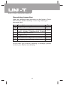
Model UT60H: OPERATING MANUAL
Table of Contents
Page
Title
Overview
Unpacking Inspection
Safety Information
Rules For Safe Operation
International Electrical Symbols
The Meter Structure
Rotary Switch
Functional Buttons
Display Symbols
Measurement Operation
A.
DC Voltage Measurement
B.
AC Voltage Measurement
C.
DC Current Measurement
D.
AC Current Measurement
E.
Measuring Resistance
F.
Testing for Continuity
G.
Testing Diodes
H.
Capacitance Measurement
I.
Frequency Measurement
J.
Temperature Measurement
K.
EF Function
L.
4~20mA Loop
Sleep Mode
Operation of Hold Mode
The use of Relative Value Mode
MAX MIN Mode
Low Impedance 200kΩ Button
POWER
The SELECT Button
General Specifications
1
3
4
5
6
9
10
11
12
13
15
15
16
17
18
20
22
23
24
26
27
28
28
29
29
30
30
31
31
31
32
Model UT60H: OPERATING MANUAL
Title
Page
Accuracy Specifications
A.
DC Voltage
B.
AC Voltage
C.
DC Current
D.
AC Current
E.
Resistance
F.
Continuity Test
G.
Diode Test
H.
Capacitance
I.
Frequency
J.
Temperature
K.
4~20mA Loop
Maintenance
A.
General Service
B.
Replacing the Fuses
C.
Replacing the Battery
2
33
33
34
34
31
35
35
35
36
36
37
37
38
38
38
39
Model UT60H: OPERATING MANUAL
Overview
This Operating Manual covers information on safety and
cautions. Please read the relevant information carefully
and observe all the Warnings and Notes strictly.
Warning
To avoid electric shock or personal injury, read the
“Safety Information” and “Rules for Safe Operation”
carefully before using the Meter.
Digital Multimeter UT60H (hereafter referred to as “the
Meter”) is a 39999 counts and 4 3/4 digits with steady
operations, fashionable structure and auto ranging
instrument. The Meter has analogue bar graph, True
RMS and full range overload protection.
The Meter not only can measure AC voltage and current,
DC voltage and current, Resistance, Capacitance,
Temperature, Frequency, Diodes, Continuity, 4~20mA Loop ,
EF Function, Max/Min, Relative Mode but also has Low
Battery Display, Data Hold and Sleep Mode features.
3
Model UT60H: OPERATING MANUAL
Unpacking Inspection
Open the package case and take out the Meter. Check
the following items carefully to see any missing or
damaged part:
Qty
Item Description
1 piece
1 English Operating Manual
2 Test Lead
1 pair
K-Type (nickel chromium ~ nickel silicon) 1 piece
3 Point Contact Temperature Probe
4
Multi-Purpose Socket
1 piece
5
Alligator Clip
1 piece
6 0.5A, 250V, Fast Type Fuse, ø 5x20mm1 piece
7 10A, 250V, Fast Type Fuse, ø 5x20mm 1 piece
8
9V Battery (NEDA 1604, 6F22, 006P) 1 piece
In the event you find any missing or damage, please
contact your dealer immediately.
4
Model UT60H: OPERATING MANUAL
5
Model UT60H: OPERATING MANUAL
Rules For Safe Operation (1)
Warning
To avoid possible electric shock or personal injury,
and to avoid possible damage to the Meter or to the
equipment under test, adhere to the following rules:
l Before using the Meter inspect the case. Donot
use the Meter if it is damaged or the case (orpart
of the case) is removed. Look for cracks or
missing plastic. Pay attention to the insulation
around the connectors.
l Inspect the test leads for damaged insulation
or exposed metal. Check the test leads for
continuity. Replace damaged test leads with
identical model number or electrical specifications
before using the Meter.
l Do not apply more than the rated voltage, as
marked on the Meter, between the terminals or
between any terminal and grounding.
l The rotary switch should be placed in the right
position and no any changeover of range shall
be made during measurement is conducted to
prevent damage of the Meter.
l When the Meter working at an effective voltage
over 60V in DC or 30V rms in AC, special care
should be taken for there is danger of electric
shock.
l Use the proper terminals, function, and range
for your measurements.
l Do not use or store the Meter in an environment
of high temperature, humidity, explosive,
inflammable and strong magnetic field. The
performance of the Meter may deteriorate after
dampened.
l When using the test leads, keep your fingers
behind the finger guards.
6
Model UT60H: OPERATING MANUAL
Rules For Safe Operation (2)
l
l
l
l
l
l
l
l
l
l
Before using the Meter inspect the case. Do
not use the Meter if it is damaged or the case
(or part of the case) is removed. Look for cracks
or missing plastic. Pay attention to the insulation
around the connectors.
Inspect the test leads for damaged insulation
or exposed metal. Check the test leads for
continuity. Replace damaged test leads with
identical model number or electrical specifications
before using the Meter.
Do not apply more than the rated voltage, as
marked on the Meter, between the terminals or
between any terminal and grounding.
The rotary switch should be placed in the right
position and no any changeover of range shall
be made during measurement is conducted to
prevent damage of the Meter.
When the Meter working at an effective voltage
over 60V in DC or 30V rms in AC, special care
should be taken for there is danger of electric
shock.
Use the proper terminals, function, and range
for your measurements.
If the value to be measured is unknown, use
the maximum measurement position.
Do not use or store the Meter in an environment
of high temperature, humidity, explosive,
inflammable and strong magnetic field. The
performance of the Meter may deteriorate after
dampened.
When using the test leads, keep your fingers
behind the finger guards.
Disconnect circuit power and discharge all highvoltage capacitors before testing resistance,
continuity, diodes.
7
Model UT60H: OPERATING MANUAL
Rules For Safe Operation (3)
l
l
l
l
l
l
l
l
Before measuring current, check the Meter’s
fuses and turn off power to the circuit before
connecting the Meter to the circuit.
Replace the battery as soon as the battery indicator
appears. With a low battery, the Meter might
produce false readings that can lead to electric
shock and personal injury.
When servicing the Meter, use only the same
model number or identical electrical specifications
replacement parts.
The internal circuit of the Meter shall not be altered
at will to avoid damage of the Meter and any accident.
Soft cloth and mild detergent should be used to
clean the surface of the Meter when servicing.
No abrasive and solvent should be used to prevent
the surface of the Meter from corrosion, damage
and accident.
The Meter is suitable for indoor use.
Turn the Meter off when it is not in use and take
out the battery when not using for a long time.
Constantly check the battery as it may leak when
it has been using for some time, replace the battery
as soon as leaking appears. A leaking battery
will damage the Meter.
8
Model UT60H: OPERATING MANUAL
International Electrical Symbols
AC or DC.
Grounding.
Double Insulated.
Warning.
Refer to the Operating
Manual.Deficiency of Built-In Battery.
Conforms to Standards of European Union.
9
Model UT60H: OPERATING MANUAL
The Meter Structure (see figure 1)
1.
2.
3.
4.
EF Sensor (front part of the housing)
LCD Display
Functional Buttons
Rotary Switch
5. Input Terminals
( figure 1)
10
Model UT60H: OPERATING MANUAL
Rotary Switch
Below table indicated for information about the rotary
switch positions.
Rotary Switch
Function
Position
AC or DC voltage measurement
V
Hz
o
C
%
EF
µA
: Resistance measurement
: Diode test
: Continuity test
Capacitance measurement
Frequency measurement
Temperature measurement
(UT60G only)
4~20mA percent measurement
Sensor Test AC 50-400V AC signal
AC or DC current measurement
(0.1µA ~4000µA)
mA
AC or DC current measurement
(0.01mA ~ 400.0mA)
A
AC or DC current measurement
range from 10mA to 10.00A
11
Functional Buttons
4
5
6
7
8
9
10
11
3
2 1
15
14
13
12
Model UT60H: OPERATING MANUAL
Measurement Operation(1)
A. DC Voltage Measurement (see figure 3)
( figure 3)
Warning
To avoid harms to you or damages to the Meter from
eletric shock, please do not attempt to measure
voltages higher than 1000V, although readings may
be obtained.
The DC Voltage ranges are: 4V, 40V, 400V and 1000V;
To measure DC voltage, connect the Meter as follows:
1. Insert the red test lead into the V terminal and the
black test lead into the COM terminal.
2. Set the rotary switch to V ;press SELECT button
to select DC measurement mode.
3. Connect the test leads across with the object being
measured.
The measured value shows on the display.
Note
l The Meter has an input impedance of 10M This
can cause measurement errors in high impedance
circuits. If the circuit impedance is less than or equal
to 10k , the error is negligible (0.1% or less).
l Special care should be taken when measuring high
voltage.
l When DC voltage measurement has been completed,
disconnect the connection between the testing leads
and the circuit under test and remove testing leads
away from the input terminals of the Meter.
15
Model UT60H: OPERATING MANUAL
Measurement Operation(3)
C. DC Current Measurement (see figure 4)
( figure 4)
Warning
Never attempt an in-circuit current measurement
where the open circuit voltage between terminals
and ground is greater than 60V DC or 30V rms.
If the fuse burns out during measurement, the Meter
may be damaged or the operator himself may be hurt.
Use proper terminals, function, and range for the
measurement.
When the testing leads are connected to the current
terminals, do not parallel them across any circuit.
Before the Meter is connected in serial to the in-circuit
being tested, turn off the power of the in-circuit..
17
Model UT60H: OPERATING MANUAL
Measurement Operation(4)
Note
l If the value to be measured is unknown, use the
maximum measurement position and reduce the
range step by step until a satisfactory reading is
obtained.
l When the measured current is 5A, continuous
measurement is allowed.
l When the measured current is between 5A-10A,
continuous measurement 10 seconds and interval
more than 15 minutes.
l When DC current measurement has been completed,
disconnect the connection between the testing leads
and the circuit under test and remove testing leads
away from the input terminals of the Meter.
D. AC Current Measurement (see figure 4)
Warning
Never attempt an in-circuit current measurement
where the open circuit voltage between terminals
and ground is greater than 60V DC or 30V rms.
If the fuse burns out during measurement, the Meter
may be damaged or the operator himself may be hurt.
Use proper terminals, function, and range for the
measurement.
When the testing leads are connected to the current
terminals, do not parallel them across any circuit.
Before the Meter is connected in serial to the in-circuit
being tested, turn off the power of the in-circuit..
18
Model UT60H: OPERATING MANUAL
Measurement Operation(5)
Note
l If the value to be measured is unknown, use the
maximum measurement position and reduce the
range step by step until a satisfactory reading is
obtained.
l When the measured current is 5A, continuous
measurement is allowed.
l When the measured current is between 5A-10A,
continuous measurement 10 seconds and interval
more than 15 minutes.
l When AC current measurement has been completed,
disconnect the connection between the testing leads
and the circuit under test and remove testing leads
away from the input terminals of the Meter.
19
Model UT60H: OPERATING MANUAL
Measurement Operation(6)
E. Measuring Resistance (see figure 5)
(figure 5)
Warning
To avoid harms to you, please do not attempt to input
voltage higher than 60V DC or 30V rms AC.
To avoid damages to the Meter or to the devices under
test, disconnect circuit power and discharge all the
high-voltage capacitors before measuring resistance.
The resistance ranges are:400Ω, 4kΩ, 40kΩ,400kΩ,
4MΩand 40MΩ.
To measure resistance, connect the Meter as follows:
1. Insert the red test lead into the Ω terminal and the
black test lead into the COM terminal.
2. Set the rotary switch to Ω
; Press SELECT
button to select Ω measurement mode.
3. Connect the test leads across with the object being
measured.
The measured value shows on the display.
20
Model UT60H: OPERATING MANUAL
Measurement Operation(7)
21
Model UT60H: OPERATING MANUAL
Measurement Operation(8)
F. Testing for Continuity (see figure 6)
(figure 6)
Warning
To avoid harms to you, please do not attempt to input
voltage higher than 60V DC or 30V rms AC.
To avoid damages to the Meter or to the devices under
test, disconnect circuit power and discharge all the
high-voltage capacitors before measuring continuity.
Note
l Open circuit voltage around –1.2V and range is 400Ω
measurement range.When continuity testing has
been completed, disconnect the connection between
the testing leads and the circuit under test and remove
the test leads away from the input terminals.
22
Model UT60H: OPERATING MANUAL
Measurement Operation(9)
G. Testing Diodes (see figure 7)
( figure 7)
Warning
To avoid harms to you, please do not attempt to
input voltages higher than 60V DC or 30V rms AC.
To avoid damages to the Meter or to the devices
under test, disconnect circuit power and discharge
all the high-voltage capacitors before testing diodes.
Use the diode test to check diodes, transistors, and
other semiconductor devices. The diode test sends
a current through the semicondutor junction, then
measure the voltage drop across the junction. A good
silicon junction drops between 0.5V and 0.8V
To test the diode out of a circuit, connect the Meter
as follows:
1. Insert the red test lead into the Ω terminal and
the black test lead into the COM terminal.
2. Set the rotary switch toΩ
and press SELECT
button to select measurement mode.
3. For forward voltage drop readings on any
semiconductor component, place the red test
lead on the component’s anode and place the
black test lead on the component’s cathode.
The red test lead polarity is “+” while the black
test lead polarity is “-“.
The measured value shows on the display.
23
Model UT60H: OPERATING MANUAL
Measurement Operation(10)
Note
l In a circuit, a good diode should still produce a forward
voltage drop reading of 0.5V to 0.8V; however, the
reverse voltage drop reading can vary depending on
the resistance of other pathways between the probe
tips.
l Connect the test leads to the proper terminals as
said above to avoid error display.
l The LCD will display OL indicating either open circuit
or wrong polarity connection.
l The unit of diode is volt (V), displaying the positiveconnection voltage-drop value.
l Open circuit voltage approximate 2.8V.
l When diode testing has been completed, disconnect
the connection between the testing leads and the
circuit under test and remove the test leads away
from the input terminals.
H. Capacitance Measurement (see figure 8)
( figure 8)
Warning
To ensure accuracy, the Meter inside is discharged
against the tested capacitor. DIS.C will be shown
on the display when it is under discharging, this
process will be quite slow. To avoid damage to the
Meter or to the equipment under test, disconnect
circuit power and discharge all high-voltage capacitors
before measuring capacitance.
Use the DC Voltage function to confirm that the
capacitor is discharged.
24
Model UT60H: OPERATING MANUAL
Measurement Operation(11)
Ω
Note
l The LCD displays OL indicating the tested capacitor
is shorted or it exceeds the maximum range.
l Analogue bar graph will be disabled when measuring
capacitance.
l It is normal to take a while when measuring high
capacitor 400 F. The analogue bar graph at this time
will show the time left before finishing the measurement.
l When capacitance measurement has been completed,
disconnect the connection between the testing leads
and the circuit under test and remove the test leads
away from the input terminals of the Meter.
25
Model UT60H: OPERATING MANUAL
Measurement Operation(12)
I. Frequency Measurement (see figure 9)
( figure 9)
Warning
To avoid harms to you, please do not attempt to input
voltage higher than 30V rms.
The measurement ranges are:40Hz, 400Hz, 4kHz, 40kHz,
400kHz, 4MHz, 40MHz and 400MHz.
To measure frequency, connect the Meter as follows:
1.
2.
3.
Insert the red test lead into the Hz terminal and
the black test lead into the COM terminal.
Set the rotary switch to Hz.
Connect the test leads across with the object
being measured.
The measured value shows on the display.
l
The requirement of Input amplitude “a” is as follows:
26
Model UT60H: OPERATING MANUAL
Measurement Operation(13)
J. Temperature Measurement (see figure10)
( figure 10)
Warning
To avoid harms to you, please do not attempt to input
voltages higher than 60V DC or 30V rms AC.
o
o
The temperature measurement range is -40 C~400 C.
To measure temperature, connect the Meter as follows:
o
1. Set the rotary switch to C, the LCD displays room
temperature.
2. Insert the multi-purpose socket into the Meter as the
figure 10.
3. Insert the point contact temperature probe into the
multi-purpose socket
4. Place the temperature probe to the object being
measured.
The measured value shows on the display after
several seconds.
Note
o
l Place the Meter in an environment of 18~23 C
otherwise false reading may be obtained especially
in testing low temperature.
l When temperature measurement has been completed,
remove the temperature probe away from the multipurpose socket, and remove the multi-purpose socket
away from the Meter.
27
Model UT60H: OPERATING MANUAL
Measurement Operation(14)
K. EF Function (see figure 11)
( figure 11)
The EF function can detect AC 50~400V.
To use EF function, connect the Meter as follows:
o
1. Set the rotary switch to C/EF and press SELECT
to select EF measurement mode.
2. Place the housing front part near the object being
measured.
3. The LCD displays “EF”. The Analogue bar graph
indicates the AC signal between 50~400V. The
buzzer also beeps in 4 different sounds grading
according to the detected signal
L. 4~20mA Loop
To use 4~20mA Loop feature, connect the Meter
as follows:
1.
Set the rotary switch to Hz%, and press SELECT to
select % measurement mode.
2. The rest procedure, please follow DC current
measurement (figure 4).
3. According to the percentage within the range of 4~
20mA displaying: <4mA display LO; 4mA display 0%
….. 20mA display 100%;>20 mA display HI
28
Model UT60H: OPERATING MANUAL
Sleep Mode
To preserve battery life, the Meter automatically turns
off if you do not turn the rotary switch or press any button
for around 30 minutes. The Meter enters into sleep mode
The Meter can be activated by turning the rotary switch or
pressing any button except POWER and Low imp. 200KΩ
button.
To disable the Sleep Mode function, press MAX MIN or
REL
button while turning on the Meter.
Operation of Hold Mode
Warning
To avoid possibility of electric shock, do not use Hold
mode to determine if circuits are without power. The
Hold mode will not capture unstable or noisy readings.
To use Hold mode, follow the following procedure:
l Press HOLD to enter Hold mode; the Meter beeps.
l Press HOLD again or RANGE or Hz % or turn
the rotary switch to exit Hold mode; the Meter beeps.
l
l
In Hold mode, HOLD is displayed.
Press and hold HOLD button when turning on the
Meter to display and keep full icons, and entering
Hold mode.
29
Model UT60H: OPERATING MANUAL
The Use of Relative Value Mode
The REL mode subtracts a stored value from the present
measurement value and displays the result.
For instance, if the stored value is 20.0V and the present
measurement value is 22.0V, the reading would be 2.0V.
If a new measurement value is equal to the stored value
then display 0.0V.
To enter or exit REL mode:
l
Press REL to enter REL mode, auto ranging turns
off, and the present measurement range is locked
and display the present measurement value as the
stored value. The present measurement value
obtained later on is the difference of the stored value.
l Press REL again to display the REL value,
is
displayed on the LCD.
l Press REL
again to step the display through the
above sequence.
l
Press REL
for more than 1 second to exit REL
mode. The Meter back to the Auto or Manual ranging
measurement mode before entering REL mode.
MAX MIN Mode
To enter or exit MAX MIN Mode, follow the following
procedures:
1.
2.
Press MAX MIN to start recording of maximum and
minimum values. Steps the display through the
sequence of high(MAX) and low(MIN) readings
Press MAX MIN for more than 1 second to exit Max
Min Mode.
30
Model UT60H: OPERATING MANUAL
Low Impedance 200kΩ Button
Warning
This button can only applies on testing voltages
lower than 250Vmax and press down the button
not more than 3 seconds.
When the Meter is under V mesaurement ranges,
press Low imp. 200 kΩ button to switch over the
input impedance from 10MΩ to around 200kΩ.
POWER
This is a self-lock button use to turn on or off the
power of the Meter
The SELECT Button
It uses for selecting the required measurement
function when there is more than one function at one
position of the rotary switch.
31
Model UT60H: OPERATING MANUAL
General Specifications
32
Model UT60H: OPERATING MANUAL
A. DC Voltage
Range Resolution
4V
40V
400V
1000V
0.0001V
0.001V
0.01V
0.1V
Accuracy
(0.1%+5)
Overload
Protection
1000V
(0.2%+5)
Remarks:
l Input impedance: Approx.10MΩ .
B. AC Voltage
Range Resolution
4V
40V
400V
750V
0.001V
0.01V
0.1V
1V
Accuracy
(1%+4)
Overload
Protection
1000V
(1.5%+4)
Remarks:
l Input impedance: Approx 10MΩ .
l Display:
a) True rms value (suitable on range’s 10%~100% )
b) AC wave peak factor:3.0 (1.5 in 1000V range)
c) Input short circuit allows *10 digits remaining
reading.
l Frequency response: 45Hz~1kHz
33
x
x
“ ”
Model UT60H: OPERATING MANUAL
MAINTENANCE(1)
This section provides basic maintenance information
including battery and fuse replacement instruction.
Warning
Do not attempt to repair or service your Meter unless
you are qualified to do so and have the relevant
calibration, performance test, and service information.
A. General Service
l
l
l
l
l
Periodically wipe the case with a damp cloth and
mild detergent. Do not use abrasives or solvents.
To clean the terminals with cotton bar with detergent,
as dirt or moisture in the terminals can affect readings.
Turn the Meter power off when it is not in use.
Take out the battery when it is not using for a long time.
Do not use or store the Meter in a place of humidity,
high temperature, explosive, inflammable and strong
magnetic field.
B. Replacing the Fuses (see figure 12)
Rubber foot
Screw
( figure 12)
38
Model UT60H: OPERATING MANUAL
MAINTENANCE(2)
Warning
To avoid electrical shock or arc blast, or personal
injury or damage to the Meter, use specified fuses
ONLY in accordance with the following procedure.
To replace the Meter’s fuse:
l Press the POWER to turn the Meter off and remove
all connections from the terminals.
l Remove the fixed rubber feet and 5 screws from the
case bottom.
l Remove the fuse by gently prying one end loose,
then take out the fuse from its bracket.
l Install ONLY replacement fuses with the identical
type and specification as follows and make sure the
fuse is fixed firmly in the bracket.
Fuse 1: 0.5A, 250V, fast type fuse, φ5x20mm
Fuse 2: 10A, 250V, fast type fuse, φ5x20mm
l Rejoin the case bottom and case top, and install the
5 screws and the rubber feet.
Replacement of the fuses is seldom required. Burning
of a fuse always results from improper operation.
C. Replacing the Battery (see figure 13)
Screw
( figure 13)
39
Model UT60H: OPERATING MANUAL
MAINTENANCE(3)
Warning
To avoid false readings, which could lead to possible
electric shock or personal injury, replace the battery
as soon as the battery indicator “
” appears.
Make sure the test leads are disconnected from the
circuit being tested before opening the case bottom.
To replace the battery:
l Press the POWER to turn the Meter off and remove
all connections from the terminals.
l Remove the screw from the battery compartment,
and separate the battery compartment from the case
bottom.
l Remove the battery from the battery compartment.
l Replace with a new 6F22 9V battery .
l Rejoin the case bottom and battery compartment,
and reinstall the screw.
** END **
This operating manual is subject to change without notice.
40
Model UT60H: OPERATING MANUAL
41
Model UT60H: OPERATING MANUAL
Copyright 2003 Uni-Trend International Limited.
All rights reserved.
Manufacturer: UNI-TREND TECHNOLOGY(DONG GUAN)LIMITED
Address: Dong Fang Da Dao, Bei Shan Dong Fang Industrial
Development District, Hu Men Town, Dong Guan City,
Guang Dong Province, China
Headquarters: Uni-Trend International Limited
Address: Rm901, 9/F, Nanyang Plaza 57 Hung To Road
Kwun Tong Kowloon, Hong Kong
Tel: (852) 2950 9168
Fax: (852) 2950 9303
Email: [email protected]
http://www.uni-trend.com
42