1
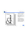
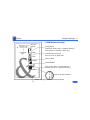
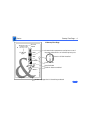
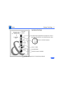
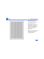
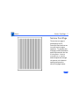
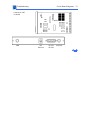
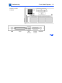
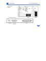
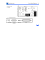
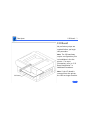
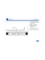
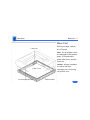
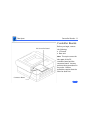
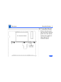
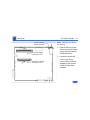
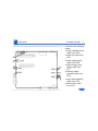
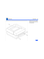
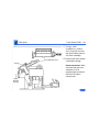
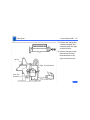
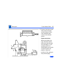
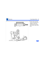
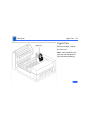
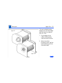
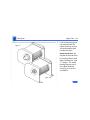
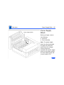
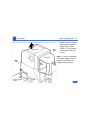
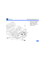
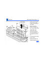
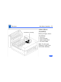
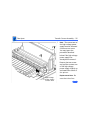
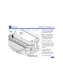
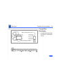
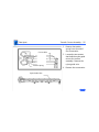
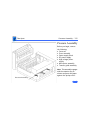
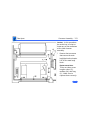
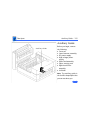
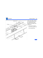
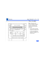
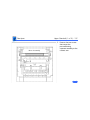
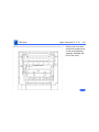
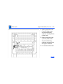
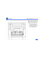
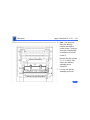
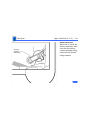
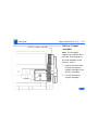
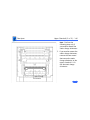
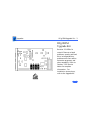
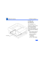
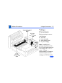
K Service Source
LaserWriter II
LaserWriter II SC, LaserWriter II NT,
LaserWriter II NTX, LaserWriter IIf, LaserWriter IIg
K Service Source
Basics
LaserWriter II
Basics
Product Information - 1
Product Information
The printers covered in this manual are
• LaserWriter II SC
• LaserWriter II NT
• LaserWriter II NTX
• LaserWriter IIf
• LaserWriter IIg
Compatibility:
Except for I/O boards components, all parts are compatible
among the five models. Refer to Illustrated Parts and Take
Apart chapters for more information. Refer to “Print
Engine Check” in Flowcharts for Troubleshooting
information.
Basics
Startup Test Page - 2
Startup Test Page
LaserWriter II printers
generate a startup test page
approximately 2 – 3
minutes after you switch on
the printer.
Except for the IISC, the
startup test page also shows
unit-specific configuration
information. The following
pages describe each element
of the startup test page.
Basics
Startup Test Page - 3
Printer
Name
I/O Board
Type
II NT/NTX StartupÊTest Page
Configuration
PostScript, Diablo 630, or Hewlett Packard
LaserJet Plus™ emulation (NTX only)
Communication Protocol
RS-232 serial or AppleTalk
Fonts in ROM
Installed RAM
Size of hard drive, if connected, and
number of fonts it contains (NTX only)
Version of ROM installed
Number of pages the I/O board has produced
Basics
Startup Test Page - 4
Printer
Name
I/O Board
Type
IIf Startup Test Page
Communication parameters and printer control
language selected for an individual printer port
Version of ROM installed
Fonts in ROM
Installed RAM
FinePrint feature enabled
Number of pages the I/O board has produced
Basics
Startup Test Page - 5
Printer
Name
I/O Board
Type
IIg Startup Test Page
Communication parameters and printer control
language selected for an individual printer port
Version of ROM installed
Fonts in ROM
Installed RAM
FinePrint feature enabled
Number of pages the I/O board has produced
Basics
Startup Test Page - 6
IISC Startup Test Page
The LaserWriter IISC test
page consists only of
vertical lines. The printer
will generate a test page
only if its SCSI address has
been set to 7 prior to
powering up.
Note: Be sure to set the SCSI
address back before you
resume printing.
Basics
Service Test Page - 7
Service Test Page
The service test page is
generated by the DC
controller board and serves
to confirm print engine
operation. To generate this
test page, remove the bottom
panel cap located at the rear
of the printer. Insert a
screwdriver or similar
dowel-shaped tool through
the quarter inch diameter
opening and press the
service test page button.
Basics
Preventive Maintenance - 8
Preventive Maintenance
Before performing any preventive maintenance, be sure to
do the following:
1
2
3
4
5
Check the page count on the startup test. If the I/O board
has been replaced or upgraded, check the repair log label
affixed to the bottom of the printer or consult with the
customer to determine page count.
Power off and unplug the printer.
Allow the fuser assembly rollers to cool.
Prepare your work area for electrostatic discharge
prevention.
Spread a drop cloth under the work area to protect the
floor from grease and spilled toner.
Caution: Never use an ammonia-based cleaner on the
Basics
Preventive Maintenance - 9
LaserWriter II. These cleaners can discolor the plastic.
Caution: Before servicing the fuser rollers, make sure that
the printer has been off at least 5 minutes to allow the fuser
assembly to cool.
The service provider should clean the following items every
12 months or during each service call.
Service Point
Tool/Solvent
Transfer corona wire
Cotton swab and isopropyl
alcohol
Primary corona wire
Transfer guide
Fuser rollers
Cleaning brush supplied with
printer
Cloth dampened with water
Fuser cleaning pad
Basics
Preventive Maintenance - 10
Service Point
Tool/Solvent
Separation claws
Cloth dampened with alcohol
Exterior case
Paper guide
Lower delivery guide
Feeder guide
Registration rollers
Cloth dampened with water
Cloth dampened with alcohol
Cloth dampened with alcohol
Cloth dampened with water
Cloth dampened with water
Basics
Parts Replacement Schedule - 11
Parts Replacement Schedule
Perform the following tasks every 50,000 prints:
• Replace the ozone filter
• Check upper and lower fan operation.
Replace the following parts every 100,000 prints:
• Fuser assembly
• Transfer guide assembly
• Preconditioning exposure assembly
• Paper feed roller assembly
• Transfer corona assembly
The LaserWriter II refurbishment kit (P/N 652-0597)
contains one each of the parts listed above.
K Service Source
Specifications
LaserWriter II
Specifications
General - 2
General
Engine
Canon SX engine
Printing Method
Electrophotography using single-component, dry toner
Optical System
Semiconductor laser and a rotating six-faced prism scanning
mirror
Resolution
300 dpi
Imaging Languages
Supported
SC: QuickDraw
NT: PostScript and a subset of the Diablo 630 printer
NTX/NTX-J: PostScript, a subset of the Diablo 630 printer, and a
subset of the Hewlett-Packard LaserJet Plus
Specifications
General - 3
f/g: PostScript Level 1 and 2 and HP LaserJet IIP (HP PCL4)
Note: NTX-J does not support emulation mode.
Specifications
Intro Dates - 4
Intro Dates
SC, NT, and NTX
July 1990
IIf and IIg
October 1991
Specifications
Logic Board - 5
Logic Board
CPU
DRAM
SC: Motorola 68000 microprocessor (7.45 MHz)
NT: Motorola 68000 microprocessor (11.16 MHz)
NTX/NTX-J: Motorola 68020 microprocessor (16.67 MHz)
f: Motorola 68030 microprocessor (20.0 MHz)
g: Motorola 68030 microprocessor (25.0 MHz)
SC: 1 MB
NT: 2 MB
NTX: 2 MB, expandable to 12 MB
NTX-J: 4 MB, expandable to 12 MB
f: 2 MB/5MB, expandable to 32 MB
g: 5 MB/8MB, expandable to 32 MB
Ê
Specifications
ROM
I/O
Logic Board - 6
SC: 16 KB
NT: 1 MB
NTX/NTX-J: 1 MB, expandable to 8 MB on expansion board
f: 2 MB standard; ROM expansion slot provided
g: 2 MB standard; ROM expansion slot provided
SC: SCSI, Apple Desktop Bus (ADB)
NT: RS-232/422, LocalTalk, ADB
NTX/NTX-J: RS-232/422, LocalTalk, SCSI, ADB
f: RS-232/422; LocalTalk; SCSI
g: RS-232/422; LocalTalk; SCSI; Ethernet
Specifications
Performance - 7
Performance
Printing Speed
8 pages per minute (all paper sizes except legal)
7 pages per minute (legal size)
Note: Actual performance depends on the application.
Duty Cycle
Minimum Life
Expectancy
Major Service
Interval
No limit in pages per month
300,000 pages
100,000 copies
Ê
Specifications
Printable Area
Performance - 8
All measurements are in inches:
SC
US Letter : 8.00 by 10.60
Legal: 6.72 by 12.50
A4: 8.00 by 11.27
B5: 6.67 by 9.43
#10 Envelopes: 3.84 by 9.10
NT, NTX, and NTX-J
US Letter : 8.00 by 10.78
Legal: 8.00 by 13.78
A4: 7.79 by 11.08
B5: 6.45 by 9.76
#10 Envelopes: 3.84 by 9.10
Specifications
Performance - 9
IIf Ê
US Letter : 8.11 by 10.79
Legal: 8.00 by 10.78 (Maximum printable area with 2 MB of
RAM. Prints up to 8.00 x 13.78 with 5 MB of RAM. Prints up
to 8.00 x 13.78 using PhotoGrade with 8 MB of RAM.)
A4: 7.89 by 11.44
B5: 6.72 by 9.81
#10 Envelopes: 3.84 by 9.10
IIg
US Letter : 8.11 by 10.79
Legal: 8.11 by 13.79 (Legal-size documents require 8 MB of
RAM to print with PhotoGrade.)
A4: 7.89 by 11.44
B5: 6.72 by 9.81
#10 Envelopes: 3.84 by 9.10
Specifications
Paper - 10
Paper
Paper Weights
Cassette Sizes
Cassette feed:16-24 lb., single-sheet, photocopy bond
Manual feed:16-36 lb., letterhead and colored stock, standardweight transparency material, envelopes, and labels
US letter standard; legal, A4, B5, and envelope cassettes optional
Cassette:200 sheets
Manual: single sheets
Envelope cassette:15 envelopes
Face-down tray:100 sheets
Capacity In
Face-up tray:20 sheets
Use manual feed for letterhead, colored stock, standard-weight
transparency material, and labels.
Specifications
Built-In Fonts - 11
Built-In Fonts
SC
NT, NTX, NTX-J
IIf, IIg
Times, Helvetica, Courier, and Symbol
Times, Helvetica, Helvetica Narrow, Courier, Symbol, Palatino,
ITC Avant Garde, ITC Bookman, New Century Schoolbook, ITC
Zapf Chancery, and ITC Zapf Dingbats
Times, Helvetica, Helvetica Narrow, Courier, Symbol, Palatino,
ITC Avant Garde, ITC Bookman, New Century Schoolbook, ITC
Zapf Chancery, ITC Zapf Dingbats, and Emulator.
Note: Built-in fonts can be expanded using an optional font
expansion board. All LaserWriter II printers support
TrueType when using LaserWriter driver 6.1 or greater.
Specifications
Environmental - 12
Environmental
Temperature
Operating: 50–90.5°F (10–33°C)
Storage:38–95° F (3–35°C)
Humidity
Operating: 20-80% relative humidity
Storage: 10-80% relative humidity
Printing: Under 60 dB(A)
Standby: Under 50 dB(A)
Specifications
Electrical - 13
Electrical
Line Voltage
Power Consumption
US/Japan:100-115 V, 50-60 Hz
Europe/Australia:220-240 V, 50 Hz
Standby:
170 W (average)
Operating:
900 W maximum (115 V)
780 W maximum (220 V)
880 W maximum (240 V)
Specifications
Physical - 14
Physical
Dimensions
Weight
Width: 20 in. (51 cm)
Depth: 18.9 in. (48 cm)
Height: 8.5 in. (21.6 cm)
46 lb. (21 kg)
K Service Source
Troubleshooting
LaserWriter II
Troubleshooting
IIf/IIg Diagnostic/ - 1
IIf/IIg Diagnostic
Set the rotary switch on the back of the printer to 4 and connect
the LaserWriter II Test Connector to the DB-25 serial port (or
simply jumper pins 4 and 22). Switch on the printer. Under
normal conditions, LEDs should flash during startup, and then fix
on the “diagnostic executing” configuration for about 2 minutes.
If no error is found, all LEDs flash and a page prints. If the LEDs
indicate an error, go to the appropriate topic in Flowcharts.
(Diagnostic Executing)
(No Error Found)
Fuser Assembly Error
Replace SIMM #2
Laser/Scanner Error
Replace SIMM #3
I/O Controller Board Error
Replace SIMM #4
Replace ROM #1
Replace SIMM #5
Replace ROM #2
Replace SIMM #6
Replace ROM #3
Replace SIMM #7
Replace ROM #4
Replace SIMM #8
Replace SIMM #1
After running this diagnostic, switch off the printer, remove the
Test Connector, and reset the rotary switch to its original setting.
Troubleshooting
Capacitor Discharge - 2
Capacitor Discharge
When there is a failure of the fusing system, the DC controller
board shuts off current to the fuser roller heater and charges
capacitor C211 to prevent overheating. If there is a failure of the
fusing system, you must turn the power off for about 30 minutes
or manually discharge the capacitor before switching power back
on.
C211
DC Controller Board
Troubleshooting
Capacitor Discharge - 3
Switch off and unplug the printer, and remove the bottom panel
and lower cover. Locate capacitor C211 on the DC controller
board. Carefully jumper the two wires at the base of the capacitor
using some kind of conductive tool, as shown on the next page.
Caution: Take care not to damage the board tracings or the
components neighboring the capacitor.
Note: There are many different tools that can be used to discharge
the capacitor: a flat blade screwdriver, paper clip, or aluminum
foil doubled over. The tool illustrated is a length of lead solder. It
has the advantage of being ductile and is less apt to damage the
controller board.
Troubleshooting
Capacitor Discharge - 4
Capacitor C211
Troubleshooting
Controller Board Readings - 5
Controller Board Readings
Voltage readings on the Canon SX engine controller board are
difficult to make and require accessing the underside of the
printer.
Rest the printer on the I/O board rails with the rear side facing
you and the near rail at the front edge of your work surface. If you
need to elevate the printer to get clearer access to the DC
controller board, use the bottom panel and lower cover.
Caution: The printer must be in an upright position during a
print cycle or while the clamshell is open.
Troubleshooting
Roller Diameters - 6
Roller Diameters
Repetitive printing defects can often be isolated by measuring the
tracking left by rollers. On the next page is a diagram that shows
all the rollers in the LaserWriter II that come into contact with
paper. The dimension given is the distance between tracks.
Troubleshooting
Roller Diameters - 7
Transfer Guide Assembly
.5" (13 mm): roller to corona assy
1.5" (38 mm): upper metallic roller
1.75" (44 mm): lower black roller
Fuser Assembly
2.56" (65 mm): lower fuser roller
3.16" (80 mm): upper fuser roller
Toner Cartridge
2.0" (51 mm): developer roller
3.75" (95 mm): photosensitive drum
Troubleshooting
Drum Check - 8
Drum Check
Interrupting a print cycle and inspecting the photosensitive drum
can help isolate the cause of print quality problems. If the image
on the surface of the drum exhibits the same problem as the
printed page, the fault is before the drum, probably somewhere in
the scanning system. If the image on the drum is okay, the fault is
after the drum, probably in the fuser assembly, transfer corona,
or high-voltage power supply.
Note: Refer to “Roller Diameters” in this chapter for further
quick-check troubleshooting tips.
Troubleshooting
Top-Cover Interlock - 9
Top-Cover Interlock
Defeating the top-cover interlock simulates a clamshell-shut
condition and is required in certain troubleshooting procedures.
You defeat this interlock by lodging a stiff, non-metallic insert
into the interlock switch. A plastic ball-point pen cap or folded
index card works well.
Troubleshooting
Top-Cover Interlock - 10
Top-Cover Interlock
Troubleshooting
Circuit Board Diagrams - 11
Circuit Board Diagrams
On the following pages are diagrams of the circuit boards and
high-voltage contacts listed below:
• LaserWriter IISC I/O board
• LaserWriter IINT I/O board
• LaserWriter IINTX I/O board
• LaserWriter IIf I/O board
• LaserWriter IIg board
• DC controller board
• Distribution board
• High-voltage contact
• Fuser board
Troubleshooting
Circuit Board Diagrams - 12
LaserWriter IISC
I/O Board
ADB
SCSI
SCSI
Switch
SCSI
Troubleshooting
Circuit Board Diagrams - 13
LaserWriter IINT
I/O Board
ROMs
ADB
DIP
Switches
RS-232
RS-422
LocalTalk
Troubleshooting
Circuit Board Diagrams - 14
LaserWriter IINTX
I/O Board
ADB
ROMs
SCSI
DIP
Switches
RS-232
RS-422
LocalTalk
Troubleshooting
Circuit Board Diagrams - 15
LaserWriter IIf
I/O Board
Pushbutton Switch
LocalTalk
RS-232
RS-422
ROMs
SCSI
SIMMs
Troubleshooting
Circuit Board Diagrams - 16
LaserWriter IIg
I/O Board
ROMs
Pushbutton Switch
LocalTalk
RS-232
RS-422
Ethernet
SCSI
SIMMs
Troubleshooting
Circuit Board Diagrams - 17
Service Test Page Button
(see “Service Test Page” in Basics)
DC Controller Board
J201
J203
J202
J212
J210
Cover Interlock Switch
C211 (see “Capacitor
Discharge” in
Troubleshooting.)
J213
J208
J207
LED201
Cassette
Microswitches
J209
J206
J205
Troubleshooting
Circuit Board Diagrams - 18
Distribution Board
Drum Sensitivity Switch SW301
Drum Sensitivity Switch SW302
DC Power Supply
Paper Pickup Roller
Solenoid SL302
Paper-Out
Sensor
PS301
Registration Clutch
Solenoid SL302
Manual-Feed
Paper Sensor
PS302
J213
Distribution
Board
Troubleshooting
Circuit Board Diagrams - 19
High-Voltage Contacts
Primary Corona
Wire Contact
Transfer Corona Contacts
(Underneath)
Developing Bias
Contact
Low Toner
Sensor Contact
Silver-Colored Screw
Primary Corona Grid Contact
Toner Cartridge Ground
Troubleshooting
Circuit Board Diagrams - 20
Fuser Board (also known as Fuser PCA)
Preconditioning Exposure
Assembly Contacts
To Thermistor TH1
Delivery Sensor PS331
(opposite face)
J333
J334
Delivery
Sensing
Lever
7
J331
1
Troubleshooting
Connector Locators - 21
Connector Locators
On the following pages are diagrams of the connectors listed below:
• Connector J103
• Connector J502
• Connector J601
Troubleshooting
Connector Locators - 22
Connector J103 connects the fuser to the fuser safety PCA inside
the power supply block. If you measure continuity between the
two pins of J103, the fuser bulb and thermoprotector are intact.
Fuser Assembly
(Removed from Printer)
J103
J103
Troubleshooting
Connector Locators - 23
Connector J502 connects the DC power supply with the power
supply block. This illustration shows the printer with the DC
power supply removed.
J502-1
J502-3
J502
Troubleshooting
Connector Locators - 24
Connector J601 connects the high-voltage power supply to J211
on the DC controller board. This illustration shows the printer
with the high-voltage power supply removed.
J601-1
J601-8
J601
Troubleshooting
Flowcharts - 25
Flowcharts
The flowcharts for this manual are contained in an interactive file
called “LaserWriter II Flowcharts.” This file has been derived
from the original version of Service Source but is a standalone
self-launching application. To launch this file, click the button
below..
I/O PCA
Connector PCA
J330
FG
SG
+24VA
NC
NC
DBDC*
-5V
DBAC*
GND
HV1ON*
+5V
HVTON*
+5VA
TPA*
TSTPT*
TPB*
RDYINH*
TSTPTE*
LPCK*
CSNT1*
SCNON*
CSNT2*
2
1
2
3
4
5
6
7
8
9
10
11
12
13
14
15
16
17
18
19
20
J209
1
FG
J206
J213
POUT*
+5V
JAML*
J210
2
1
5
4
+24VA
GND
RDYL*
3
1
2
3
4
5
6
7
8
1
2
4
3
5
6
9
8
7
3
2
1
7
6
5
4
HVTON(SB)
HVRST(PK)
HV10N(GY)
DBAC*(V)
TSENS(Y)
DBDC*(V)
GND(BL)
+24B(R)
CSENS1*
CSENS2*
CPUD
REGD
+24V
GND
MPFS*
PEMP*
+5V
PEXP(Y)
GND 24V(BL)
+24V (R)
+5V(BR)
PDP*(SB)
GND(BL)5V
FSRTH(PK)
1
2
3
4
5
6
7
3
2
1
7
6
5
4
Discharging
Pins
Primary
Corona
DrumSensitivity
Switches
SW302
SW301
Pickup
Roller
Solenoid
SL301
GND +5V
PS302
ManualFeed Paper
Sensor
J601
8
1
2
4
3
5
6
9
8
7
+24V GND
Status Panel
PPRDY*
B9
J205
A16
VSREQ*
B8
J205
A15
A14
A13
STS*
B7
B10 FG
VSYNC*
CBSY*
B5
B6
FSRD* (PK)
GND (BL)
+24VA (R)
FAN (SB)
DC Power Supply
A12
A11
A10
VDO*
B4
2
3
4
1
J602
Transfer
Corona
1
2
J603
1
Developer
Bias
(AC&DC)
TB
601
TB
602
2
Low Toner
Sensor
TB
603
TB
605
TB
604
GND
Registration
Solenoid
SL302
+24V
GND +5V
PS301
Paper
Out
Preconditioning
Exposure
Circuit
Paper
Delivery
Sensor
PS331
3
4
J334
1
TB
321
J333
+24V
J332
TH1
TB
322
2
HEATER
BULB
Fuser PCA
A9
RDY
CCLK*
B2
B3
B1
2 PD
1 DSADJ
A8
RDY*
A9
J208
A7
SBSY*
A8
J331
A6
PCLK*
A7
2
Thermo-Protector
A4
A5
A3
PRNT*
A6
1
J101
TP1
A2
B11
B10
B1
CPRDY*
A5
A10 BD*
CMD*
A4
J212
J152 1 2
+24VDC
J103
Fuser
1
Safety
PCA
2
B9
N/C
Top Cover
Interlock
+24VDC
B8
B7
B6
B5
B4
GND(FG)
FG+
GND(FG)
FG-
N/C
J203
7 +24VA
6 GND
5 SCNCONT
A3
J202
5 FG
A2
3
1 AC-COLD 1
3 AC-HOT
CB1
B3
1
F1
6 5 4 3 2 1
J3
Noise
Filter
B2
2
4
3
2
1
A1
J401
5
4
3
A1
3
4
B16
J451
1
2
GND
GND
+5V
+5V
-5V
RESET
REMOTE*
A
A*
B
B*
GND
+24VB
+24VA
J502
B15
1
2
3
4
5
6
7
8
9
10
11
12
13
14
J104
B14
Optical
Fiber
J201
Main
Motor
B13
B12
Laser
Diode PCA
Power Supply
Block
Connector PCA
+5V
Scanning
Motor PCA
Laser/Scanner Assembly
Upper
Fan
Fuser Assembly
Toner Cartridge
Preconditioning
Exposure
Assy
Distribution PCA
J603
Primary Corona Grid
High
Voltage
Power
Supply
J211
4 +5V
3 LDRV
DC Controller PCA
J207
Lower
Fan
J331
Ready/Wait LED
Paper-Out LED
Paper-Jam LED
TEMPL*
Low-Toner LED
LaserWriter II
Wiring Diagram 110V
K Service Source
Take Apart
LaserWriter II
Take Apart
I/O Board - 1
I/O Board
No preliminary steps are
required before you begin
this procedure.
Note: The I/O board may
require configuration prior
to installation in the the
printer. For more
information, refer to “I/O
Board Installation” in
Additional Procedures.
I/O Board
Note: If the I/O board is
removed from the printer,
the LEDs no longer function.
Take Apart
I/O Board - 2
1
2
I/O Board
Loosen the two screws
that secure the I/O board
to the chassis.
Caution: Handle the
board by the metal
bracket only.
Carefully slide the I/O
board out of the printer.
Take Apart
Base Unit - 3
Base Unit
Before you begin, remove
the I/O board.
Lower Fan
Note: This procedure covers
the take apart of the bottom
panel, I/O board shield
plate, lower cover, and the
lower fan.
Caution: Always remember
to remove the toner
cartridge prior to turning
the printer over.
Lower Cover
Ê
I/O Board Shield Plate
Bottom Panel
Take Apart
Base Unit - 4
1
2
Bottom Panel
3
Place the printer on its
back on a padded work
surface.
Remove the seven screws
that secure the bottom
panel to the metallic
lower cover.
Remove the bottom
panel.
Take Apart
Base Unit - 5
4
I/O Board
Shield Plate
Remove the two screws
that secure the I/O board
shield plate to the lower
cover. Remove the
shield plate.
Take Apart
Base Unit - 6
5
6
Lower Cover
Remove the nine screws
that secure the lower
cover to the printer
chassis.
Lift the lower cover and
slide it free at the I/O
board guide rails.
Take Apart
Base Unit - 7
Lower Fan
Lower Fan
Note: If you need to remove
the lower fan, perform the
following procedure.
1
2
3
Disconnect the fan cable
from DC controller
board connector J207.
Remove the four screws
that secure the fan to the
chassis.
Remove the fan and the
fan bracket.
Take Apart
Controller Boards - 8
Controller Boards
DC Controller Board
Before you begin, remove
the following:
• I/O board
• Base unit
Note: This topic covers the
take apart of the DC
controller board and the
connector board. You may
perform these procedures in
any order. Neither
procedure requires that the
other be done first.
Connector Board
Take Apart
Controller Boards - 9
DC Controller Board
1
DC Controller Board
I/O Board
Guide Rail
Remove the two screws
that secure the I/O board
guide rail to the chassis
and move the guide rail
away from the DC
controller board.
Take Apart
Controller Boards - 10
Cover Interlock
Switch Actuator
Note: Cabling is not shown
for clarity.
2
DC Power Supply
Connector J212
Distribution Board
Connector J213
3
Remove the two screws
that secure the DC power
supply and distribution
board connectors.
Loosen the screw that
secures the lowercover interlock switch
actuator to the chassis
and lift off the metal
actuator.
Take Apart
Controller Boards - 11
4
Disconnect the following
cables:
• Fuser assembly board
cable from J206
• Lower fan cable from
J207
• Power supply block
cable from J208
• High-voltage power
supply cable from
J211
• Scanning motor
assembly cable from
J203
• Laser diode assembly
cable from J202
• Optical fiber cable
from J201
Take Apart
Controller Boards - 12
5
6
Power Lugs
Remove the two screws
that secure the power
lugs to the connector
board.
Remove the four screws
that secure the DC
controller board to the
chassis.
Take Apart
Controller Boards - 13
7
Note: The two DC power
supply connectors offer
some resistance when
you are removing the DC
controller board. If you
want to alleviate this
problem, remove the
four screws that secure
the connector to the
board, remove the cables
from the connector, and
then proceed with
removing the board. Be
sure that you screw the
connector back in before
returning the controller
board to Apple.
Take Apart
Controller Boards - 14
Jumper
8
Carefully grasp the DC
controller board by the
edges and pull the board
firmly up and away from
the connector board.
Remove the jumper at
J209, if one is present.
Take Apart
Controller Boards - 15
Connector Board
Power Lugs
1
2
Connector
Board
3
Disconnect the status
panel cable from
connector J331.
Remove the two screws
that secure the power
lugs to the connector
board.
Remove the three screws
that secure the connector
board to the chassis.
Take Apart
Controller Boards - 16
4
Screw
5
Connector
Board
Remove the screw at the
corner of the DC
controller board nearest
the power lugs.
Lift the corner of the DC
controller board slightly
and slide out the
connector board.
Take Apart
Cover Set - 17
Cover Set
Cover Set
No preliminary steps are
required before you begin
this procedure.
Note: This procedure covers
the take apart of the cover
set, including the release
button and LED status panel
Take Apart
Cover Set - 18
1
Remove the four screws
that secure the cover set
to the printer.
Take Apart
Cover Set - 19
2
3
Release
Button
Depress the release
button and open the top
cover.
Remove the three
interior screws along
the rim of the cover set.
Take Apart
Cover Set - 20
4
Remove the two interior
screws that secure the
cover set bracket to the
chassis.
Take Apart
Cover Set - 21
5
LED Status Panel
Note: If you need to
monitor status panel
lights when the cover is
off, don’t disconnect the
connector. Simply
remove the two screws
and lift the whole status
panel off the cover.
Lift up the cover set and
remove it far enough to
disconnect the connector
from the LED status
panel.
Take Apart
Cover Set - 22
6
Set aside the cover set.
Note: The cover set is made
up of front, rear, upper
right, and lower right
panels. Each panel can be
taken apart by removing the
appropriate screws.
Release Button
1
Release Button
To remove the release
button, squeeze the
arms of the button and
remove it from the
upper right panel.
Take Apart
Clamshell Detachment - 23
Clamshell
Clamshell
Detachment
Before you begin, remove
the following:
• Cover set
• Fuser assembly
Note: The clamshell is what
hinges upward when you
open the printer. It is not
available from Apple as an
assembly, but you may need
to remove it in the course of
removing other assemblies.
Take Apart
Clamshell Detachment - 24
1
Left Hinge
Assembly
Remove the four screws
that secure the left and
right hinge assemblies
to the chassis and lift off
the upper clamshell
(right hinge assembly
not shown).
Replacement Note: Cradle
the clamshell in an upright
position and secure the right
hinge assembly to the
printer chassis. Then
secure the left hinge
assembly. Make sure the
screws are tight.
Take Apart
Laser/Scanner Assembly - 25
Laser/Scanner Assembly
Laser/Scanner
Assembly
Before you begin, remove
the cover set.
Note: The LaserWriter II
laser/scanner assembly is
available only as an integral
assembly. No subcomponent
is available from Apple and
no adjustments to laser
power circuitry can be
made. See “Laser Power
Output Check” under
Additional Procedures for
measurement procedures.
Take Apart
Laser/Scanner Assembly - 26
1
Disconnect the cable
from laser diode board
connector J451.
Take Apart
Laser/Scanner Assembly - 27
2
Cover
Scanning Motor Cable
Open the cover that
accesses the scanning
motor board and
disconnect the scanning
motor cable.
Take Apart
Laser/Scanner Assembly - 28
Optical Fiber Cable
Cover
3
4
Remove the screw on the
optical fiber cover and
open the cover.
Carefully lift the optical
fiber cable up and out of
its slot in the laser/
scanner assembly.
Replacement Note: Make
sure that the collar on
the optical fiber seats
properly in the slot
before closing the cover.
Take Apart
Laser/Scanner Assembly - 29
5
6
Remove the four long
screws that secure the
laser/scanner assembly
to the main body block.
Remove the laser/
scanner assembly.
Note: Make sure that the
optical fiber and laser
harness cables are removed
when you return a defective
laser/scanner assembly to
Apple.
Take Apart
Fuser Assembly - 30
Fuser Assembly
Fuser Assembly
No preliminary steps are
required before you begin
this procedure.
Note: The fuser assembly
consists of several orderable
components and subassemblies (see Illustrated
Parts).
Take Apart
Fuser Assembly - 31
Note: This procedure covers
only the removal of the
fuser assembly from the
printer. The topics that
follow this one address
further disassembly of the
fuser assembly:
• Fuser Delivery Assembly
• Fuser Heater Bulb
• Delivery-Sensing Lever
1
Depress the release
button and open the top
cover.
Take Apart
Fuser Assembly - 32
Fuser
Assembly
2
3
Remove the four screws
that secure the fuser
assembly to the chassis.
Lift the fuser straight up
out of the printer.
Replacement Note: Make
sure that the 7-pin
connector on the fuser
board mates properly
with the receptacle.
Fuser
Board
Note: Before returning the
fuser assembly to Apple,
remove the cleaning felt and
replace it with the roller
separators that come with
the exchange unit.
Take Apart
Fuser Delivery Assembly - 33
Fuser Delivery
Assembly
Fuser
Delivery
Assy
Before you begin, remove
the fuser assembly.
Note: The fuser delivery
assembly is an orderable
subassembly of the fuser
assembly. Its function is to
separate the page as it exits
the fuser rollers and to feed
it toward the delivery tray.
Take Apart
Fuser Delivery Assembly - 34
1
Tension Spring
2
3
4
Fuser Delivery
Assembly
Open the fuser delivery
assembly.
Unhook the two tension
springs that connect the
fuser delivery assembly
to the fuser assembly.
Remove the two screws
that secure the fuser
delivery assembly to the
fuser assembly.
Remove the fuser
delivery assembly.
Take Apart
Fuser Delivery Assembly - 35
Delivery Rollers
Note: The delivery rollers
are the white serrated
rollers within the fuser
delivery assembly.
C-Rings
C-Ring
1
If you need to replace a
delivery roller, remove
the three C-rings that
secure the delivery
roller shaft to the fuser
delivery assembly.
Take Apart
Fuser Delivery Assembly - 36
2
Bushing
Bushing
Delivery Roller Shaft
Push the bushings
toward the center of the
delivery roller shaft.
Take Apart
Fuser Delivery Assembly - 37
3
Note: Be careful not to
lose the tiny delivery
roller gear pin that
falls out when you
remove the gear in the
following step.
Slide the delivery roller
shaft away from the
gear arm and rotate the
gear arm off the shaft.
Delivery Roller Shaft
Take Apart
Fuser Delivery Assembly - 38
4
Delivery Roller Gear
Remove the delivery
roller gear from the
delivery roller shaft.
Take Apart
Fuser Delivery Assembly - 39
5
Note: The delivery
rollers rest loosely
within slots in the fuser
delivery assembly and
may fall out when you
remove the roller shaft.
Remove the delivery
roller shaft and lift out
the delivery roller.
Delivery
Rollers
Take Apart
Fuser Heater Bulb - 40
Fuser Heater Bulb
Fuser Heater Bulb
Before you begin, remove
the fuser assembly.
Note: The fuser heater bulb
is an orderable subcomponent of the fuser
assembly. It provides the
heat necessary to fuse toner
to paper.
Take Apart
Fuser Heater Bulb - 41
1
2
3
4
Fuser Cover
Left Contact Cap
Cleaning Felt
(Inside)
Open the fuser delivery
assembly.
Loosen the screw (1)
that secures the fuser
cover to the fuser
assembly.
Lift the fuser cover and
the fuser cleaning felt.
Remove the screw (2)
that secures the left
contact cap to the fuser
assembly. Lift off the
cap.
Take Apart
Fuser Heater Bulb - 42
5
6
Remove the two screws
that secure the fuser
board to the fuser
assembly.
Note: The fuser board
will hang loosely from
the fuser assembly after
the following step. Be
careful when handling
either part.
Detach the fuser board
from the fuser assembly.
Take Apart
Fuser Heater Bulb - 43
7
8
Left Terminal Mount
Remove the three screws
that secure the left
terminal mount to the
fuser assembly.
Remove the terminal
mount.
Take Apart
Fuser Heater Bulb - 44
9
Left Heater Support
Remove the screw that
secures the left heater
support to the fuser
assembly. Remove the
support.
Take Apart
Fuser Heater Bulb - 45
10 Remove the screw that
secures the right
contact cap to the fuser
assembly. Remove the
cap.
Right Contact Cap
Replacement Note:
Before replacing the
contact cap, make sure
that the heater bulb
grounding lead wraps
around the positioning
posts on top of the
terminal mount.
Take Apart
Fuser Heater Bulb - 46
11 Using a small
screwdriver, remove
the E-ring that secures
the drive release cam to
the fuser assembly.
Drive Release Cam
E-Ring
Drive
Release
Spring
12 Remove the drive release
cam and the spring.
Replacement Note: Make
sure that the gear arm
assembly is in an
upright position behind
the toe of the drive
release cam.
Take Apart
Fuser Heater Bulb - 47
13 Remove the spring that
connects the gear arm
assembly with the right
terminal mount.
14 Remove the two screws
that secure the fuser
bulb connector to the
right terminal mount.
Spring
Right Terminal Mount
Gear Arm
Assembly
Take Apart
Fuser Heater Bulb - 48
15 Remove the three screws
that secure the right
terminal mount to the
fuser assembly and
remove the terminal
mount.
Replacement Note:
When you replace the
right terminal mount,
make sure that the gear
arm assembly is in an
upright position as
shown before you set the
terminal mount into
position. Note the
position of the spring on
the previous page.
Take Apart
Fuser Heater Bulb - 49
16 Remove the screw that
secures the right heater
support to the fuser
assembly and carefully
slide out the fuser heater
bulb.
Right Heater Support
Take Apart
Delivery-Sensing Lever - 50
Delivery-Sensing
Lever
Before you begin, remove
the fuser assembly.
Note: The delivery-sensing
lever is an orderable
subcomponent of the fuser
assembly. This lever, in
combination with a sensor
on the fuser board, is the
sole monitor of paper jams
in the LaserWriter II
printer.
Delivery-Sensing Lever
Take Apart
Delivery-Sensing Lever - 51
Original
New
Note: There are two
versions of the deliverysensing lever. In the new
version, the shape of the
counterweight has been
enlarged (A).
Take Apart
Delivery-Sensing Lever - 52
1
2
Fuser Delivery
Assembly
Delivery-Sensing Lever
Open the fuser delivery
assembly.
Carefully pull the
delivery-sensing lever
out of the fuser
assembly.
Take Apart
Feeder Assembly - 53
Feeder Assembly
Feeder Assembly
Before you begin, remove
the fuser assembly.
Take Apart
Feeder Assembly - 54
1
2
Main Motor Drive
Assembly Cover
Remove the screw that
secures the main motor
drive assembly cover to
the main motor mount.
Remove the cover.
Take Apart
Feeder Assembly - 55
3
Remove the four screws
that secure the feeder
assembly to the chassis.
Remove the feeder
assembly.
Replacement Note: Make
sure to engage the tab at
the front of the feeder in
the slot in the main body
block.
Feeder Assembly
Take Apart
Ozone Filter - 56
Ozone Filter
Filter Case
No preliminary steps are
required before you begin
this procedure.
Caution: Be careful when
handling the ozone filter. It
is brittle and can break if
handled roughly.
Take Apart
Fan
Ozone
Filter
Filter
Access
Door
Ozone Filter - 57
Note: There are two filter
case designs. In the newer
design, you access the ozone
filter through a special
access door. In the earlier
design you must remove the
cover set and filter case
from the printer before
removing the ozone filter.
Ozone Filter (New)
1
Open the access door.
Pull on the ozone filter
tab and slide the filter
out of the case.
Take Apart
Ozone Filter - 58
Ozone Filter (Old)
1
Fan
Filter Case
2
3
Remove the two screws
that secure the filter
case to the fan.
Pull the filter case and
fan duct straight up and
out of the printer.
To remove the ozone
filter, slide it down and
out of the filter case.
Take Apart
Upper Fan - 59
Upper Fan
Upper Fan
Before you begin, remove
the cover set.
Note: Also included in this
topic are the take apart of
the fan bushing/bearing.
Take Apart
Upper Fan - 60
1
2
Fan
Filter Case
Remove the two screws
that secure the filter
case to the fan.
Pull the filter case and
fan duct straight up and
out of the printer.
Take Apart
Upper Fan - 61
3
4
Fan
Cable
(opp. side)
Remove the three screws
that secure the fan to the
power supply block.
Disconnect the cable
from the power supply
block and remove the
fan.
Take Apart
Upper Fan - 61
3
4
Fan
Cable
(opp. side)
Remove the three screws
that secure the fan to the
power supply block.
Disconnect the cable
from the power supply
block and remove the
fan.
Take Apart
Upper Fan - 62
Fan Bushing/Bearing
Type "T"
There are two versions of
the upper fan, each with a
distinct bushing/bearing
design. The Type “JP”
design is 5/8" in diameter
and rests flat against the
side of the fan; the Type “T”
design is 7/8" in diameter
with a knob that protrudes
from the side of the fan.
Type "JP"
Take Apart
Upper Fan - 63
The two bushing/bearing
designs are not interchangeable and must be replaced
like-for-like.
Type "T"
1
2
Type "JP"
Pry the edges of the
rubber bushing away
from the side of the fan.
When the rubber
bushing is loose, pull the
bushing/bearing off the
fan motor shaft.
Take Apart
Upper Fan - 64
3
Type "T"
If the metal bearing was
not removed with the
rubber bushing, remove
the metal bearing with
needlenose pliers.
Replacement Note: Do
not push on the end of the
protruding rubber knob
when installing the Type
“T” design. The metal
bearing may pop out of
the rubber bushing,
resulting in incorrect
installation.
Type "JP"
Take Apart
Power Supply Block - 66
Power Supply Block
Power Supply
Block
Before you begin, remove
the following:
• Cover set
• Fuser assembly
Note: The power supply
block sits directly beneath
the upper fan and is the
point where line voltage
enters the printer.
Included in the power supply
block are the power switch,
the fuser safety board, and
circuit breaker CB1.
Take Apart
Power Supply Block - 67
1
Upper Fan
Fan Duct
Power Supply
Block
Remove the four screws
that secure the power
supply block to the
chassis. Lift the power
supply block from the
printer.
Note: If you are returning
the power supply block to
Apple, first remove the
upper fan and fan duct.
Take Apart
DC Power Supply - 68
DC Power Supply
DC Power Supply
Before you begin, remove
cover set.
Note: This procedure
covers the take-apart of
the DC power supply and
the fuse. See next topic
for removal of the
distribution board.
Take Apart
DC Power Supply - 69
1
Laser/scanner cables
Right Support Plate
Remove the laser/
scanner cables from the
cable clip behind the
right support plate.
Take Apart
DC Power Supply - 70
2
Remove the status panel
cables from the four
cable clips on the right
support plate.
Replacement Note:
When re-stringing the
status panel cables, be
sure that the ferrite
bead falls between the
two rear cable clips.
Ferrite bead
Take Apart
DC Power Supply - 71
3
Right Support
Plate
Remove the six screws
that secure the right
support plate to the
chassis. Set aside the
support plate.
Take Apart
DC Power Supply - 72
Fiber Optic Cable
4
Fuse
5
Main Motor
Note: The fuse is located
at the rear opening of the
DC power supply. To
remove the fuse, gently
pry it loose from its
socket. No further take
apart is needed.
Disconnect the main
motor cable from DC
power supply connector
J3.
Remove the fiber optic
cable from its holder on
the distribution cover.
Take Apart
DC Power Supply - 73
6
DC Power
Supply
7
Remove the three screws
that secure the DC power
supply to the chassis.
Replacement Note:
Failure to install the DC
power supply screws
could result in erratic
test results due to poor
electrical connections.
Firmly lift the DC power
supply straight up and
out of the printer.
Note: First remove the
distribution board and
cover before returning the
DC power supply to Apple.
Take Apart
Distribution Board - 74
Distribution Board
Before you begin, remove
the following:
• Cover set
• DC power supply
Distribution Board
Note: The distribution
board is the board that
distributes power from the
DC controller board to the
clutch solenoids, paper
sensors PS301 and PS302,
and the toner cartridge
contact sensors. The
distribution board is
attached to the face of the DC
Power Supply when you
Take Apart
Distribution Board - 75
DC Power Supply
remove the DC Power
Supply from the printer.
1
Screw
Distribution
Board Cover
2
Distribution Board
Remove the screw that
secures the distribution
board cover to the DC
power supply.
Remove the cover.
Take Apart
Distribution Board - 76
3
DC Power Supply
4
Distribution Board
Remove the six screws
that secure the
distribution board to the
DC power supply.
Remove the distribution
board.
Take Apart
High-Voltage Power Supply - 77
High-Voltage
Power Supply
Before you begin, remove
the cover set.
High-Voltage
Power Supply
Take Apart
High-Voltage Power Supply - 78
1
Laser/Scanner Cables
Clip
Right Support Plate
Remove the laser/
scanner cables from the
cable clip behind the
right support plate.
Take Apart
High-Voltage Power Supply - 79
2
Remove the status panel
cables from the four
cable clips on the right
support plate.
Replacement Note:
When re-stringing the
status panel cables, be
sure that the ferrite
bead falls between the
two rear cable clips.
Ferrite Bead
Take Apart
High-Voltage Power Supply - 80
3
Right Support
Plate
Remove the six screws
that secure the right
support plate to the
chassis. Set aside the
support plate.
Take Apart
High-Voltage Power Supply - 81
High-Voltage
Power Supply
4
5
Remove the four screws
that secure the highvoltage power supply to
the chassis.
Replacement Note:
Failure to reinstall the
four screws snugly could
cause erratic test
results due to poor
electrical connections.
The screw marked (1) is
the long silver colored
one.
Lift out the high-voltage
power supply.
Replacement Note: Be
sure the connector on the
Take Apart
High-Voltage Power Supply - 82
bottom of the highvoltage power supply
mates properly with the
receptacle.
Take Apart
Main Motor Assembly - 83
Main Motor Assembly
Main Motor
Assembly
Before you begin, remove
the following:
• Cover set
• Fuser assembly
• Power supply block
• DC power supply
Note: The drive gear
assembly is a part of the
main motor assembly.
Take Apart
Main Motor Assembly - 84
1
Main
Motor
Remove the five screws
that secure the main
motor assembly to the
chassis. Lift out the
main motor.
Take Apart
Main Motor Assembly - 85
2
Drive Gear Assembly
3
To remove the drive gear
assembly, remove the
four screws that secure
it to the main motor.
Separate the main motor
from the drive gear
assembly.
Take Apart
Transfer Guide Assembly - 86
Transfer Guide Assembly
Transfer Guide
Assembly
Before you begin, remove
the cassette tray.
Note: This procedure also
covers the take apart of the
separation pad.
1
Separation Pad
Depress the release
button and open the top
cover.
Take Apart
Transfer Guide Assembly - 87
2
Upper
Transfer
Guide
Remove the two screws
that secure the upper
transfer guide to the
upper transfer
assembly.
Take Apart
Transfer Guide Assembly - 88
3
Transfer
Guide
Assembly
Remove the two screws
that secure the transfer
guide assembly to the
cassette holder. Lift the
transfer guide assembly
from the printer.
Take Apart
Transfer Guide Assembly - 89
Replacement Note: Make
sure that the copper
collar at the end of the
roller shaft is positioned
beneath the adjacent
plate.
Collar (shown in correct position)
Take Apart
Transfer Guide Assembly - 90
Separation Pad
Separation Pad
1
2
Leaf Spring
If you need to replace the
separation pad, remove
the two screws that
secure the leaf spring
and separation pad to the
transfer guide assembly.
Lift off the separation
pad.
Take Apart
Transfer Corona Assembly - 91
Transfer Corona Assembly
Transfer Corona
Assembly
Before you begin, remove
the following:
• Cover set
• Transfer guide assembly
Note: This procedure also
covers the restringing of the
corona wire.
Take Apart
Transfer Corona Assembly - 92
1
Note: The contact arm of
the high-voltage power
supply must be loosened
for access to a screw.
You may ignore the
procedure described
below if the high-voltage
power supply has
already been removed .
Remove the two screws
and pull the contact arm
of the high-voltage
power supply slightly up
and toward the center of
the printer.
High-Voltage
Power Supply
Contact Arm
Replacement Note: Be
sure that the silver-
Take Apart
Transfer Corona Assembly - 93
colored screw (1) goes
into the grounding hole
closest to the fuser.
Transfer
Corona
Assembly
2
3
Discharging Pins and
Contacts (Underneath)
Note: The discharging
pins and contacts are
accessible at this point
for inspection and
cleaning, if need be.
Remove the two screws
that secure the transfer
corona assembly to the
chassis.
Lift the side of the
transfer corona
assembly closest to the
drive gears and pull it
out of the printer.
Take Apart
Transfer Corona Assembly - 94
Right Termination Cover
Left Termination Cover
Corona Wire
Restringing
1
Unsnap and remove both
corona wire termination
covers.
Take Apart
Transfer Corona Assembly - 95
2
Corona Wire
Tension Spring
Nylon Guide Wire
3
4
Remove the tension
spring from the end of
the corona wire.
Loosen the two screws
that hold the nylon guide
wire to the corona
assembly. Remove the
nylon guide wire.
Remove the corona wire.
Take Apart
Transfer Corona Assembly - 96
5
Retaining
Pin
End of Corona Wire
6
Fold back approximately
1/4 “ length of the new
corona wire and twist
six to eight times to
form a loop at the end of
the wire.
Hook the looped end over
the retaining pin at the
right end of the
assembly.
Take Apart
Transfer Corona Assembly - 97
7
Corona Wire
Terminal
Tension
Spring
8
9
Stretch the wire across
the length of the corona
assembly until it
reaches the corona wire
terminal.
Loop the left end of the
wire in the same manner
as the right.
Hook one end of the
tension spring onto the
loop and the other end of
the spring onto the
corona wire terminal.
Note: The wire should be
clean and without kinks
and taut enough to
remain straight.
Take Apart
Transfer Corona Assembly - 98
Right Termination Cover
Left Termination Cover
Starting Screw
Ending Screw
10 Replace the termination
covers.
11 Fasten one end of the
guide wire with the
screw at location 1, wind
the wire tightly around
the corona assembly in
the order shown, and
fasten the other end of
the wire with the screw
at location 16.
Take Apart
Paper Feed Assembly - 99
Paper Feed
Assembly
Before you begin, remove
the following:
• Cover set
• DC power supply
Note: This procedure covers
the take apart of the paper
feed assembly and the
removal of the pickup
roller.
Paper Feed
Assembly
Take Apart
Paper Feed Assembly - 100
1
2
Paper Feed Assembly
Remove the two screws
that secure the paper
feed assembly to the
main body block (screw
at left end not shown).
Pull the paper feed
assembly out of the
main body block toward
the rear of the printer.
Take Apart
Paper Feed Assembly - 101
Roller
Cam
3
Pickup Roller
C-Rings
Mounting Collar
Washer
4
Cross Section
of Pickup Roller
To remove the pickup
roller from the paper
feed assembly, remove
the following items
from the paper feed
roller shaft.
• Two C-rings
• Washer
• Mounting collar
• Roller
• Cam
Slide off the pickup
roller.
Replacement Note: Clean all
rollers and cams prior to
replacing the paper feed
assembly. Failure to do so
Take Apart
Paper Feed Assembly - 102
could cause stains on printed
pages.
When installing the pickup
roller and cam, be sure that
their flat edges align on the
same side.
Take Apart
Paper-Sensing Arm - 103
Paper-Sensing
Arm
Before you begin, remove
the following:
• Cover set
• DC power supply
Caution: The arm is not
designed to snap out of the
mounting collar. Trying to
do so can break the arm.
Paper-Sensing Arm
Take Apart
Paper-Sensing Arm - 104
Mounting
Collar
Paper
Sensing
Arm
1
Remove the screw from
the mounting collar and
pull the sensing arm and
collar out of the main
body block toward the
rear of the printer.
Take Apart
Paper-Sensing Arm - 105
2
Beveled
Notch
Mounting
Collar
Rotate the mounting
collar 180° relative to
the paper-sensing arm,
slide the bracket so that
it aligns with the beveled
notch in the arm, and
separate the arm from
the mounting collar.
Replacement Note: Make
sure that the inside
leading edge of the arm
seats properly in the
auxiliary guide.
Paper-Sensing Arm
Take Apart
Paper Feed Drive Assembly - 106
Paper Feed
Drive Assembly
Paper Feed Drive
Assembly
Before you begin, remove
the following:
• Cover set
• Fuser assembly
• Power supply block
• DC power supply
• Main motor assembly
• Transfer guide assembly
• Transfer corona assembly
Note: The paper feed drive
assembly is the geared
mechanism that transfers
mechanical drive from the
main motor to the transfer
Take Apart
Paper Feed Drive Assembly - 107
guide assembly and paper
feed assembly.
This procedure also entails
the removal of the 19-tooth
paper pickup gear and the
57-tooth paper pickup gear.
Take Apart
Paper Feed Drive Assembly - 108
Paper Feed Drive
Assembly
1
Note: It is necessary to
unscrew and loosen the
collar bracket at the
gear end of the paper
feed assembly to gain
access to perform this
procedure.
Remove the three screws
that secure the paper
feed drive assembly to
the main body block.
Take Apart
Paper Feed Drive Assembly - 109
2
C-Ring
Remove the C-ring that
keeps the drum drive
shaft in place.
Take Apart
Paper Feed Drive Assembly - 110
3
Drum Drive Shaft
Slide the drum drive
shaft through the body
block supports toward
the rear of the printer.
Take Apart
Paper Feed Drive Assembly - 111
4
19-Tooth
Pickup Gear
57-Tooth
Paper Pickup
Gear
Lift out the 19-tooth
paper pickup gear.
Note: If you need to inspect
or replace it, slide out the
57-tooth paper pickup gear.
Take Apart
Paper Feed Drive Assembly - 112
5
Paper Feed Drive
Assembly
Lift out the paper feed
drive assembly.
Take Apart
Hook/Lifter Assemblies - 113
Right
Hook/Lifter
Assembly
Left
Hook/Lifter
Assembly
Hook/Lifter
Assemblies
Before you begin, remove
the cover set.
Note: The hook/lifter
assemblies are latching and
release mechanisms for the
upper clamshell and are
available as component parts
only (see Illustrated Parts).
These assemblies consist of a
hook, lifter, and hook guide
on either side of the laser/
scanner assembly. The
parts are not interchangeable from left to right.
Take Apart
Hook/Lifter Assemblies - 114
Right Hook
Right Hook/Lifter
Assembly
Metal Bracket
Note: Removal of the DC
power supply is required
for access to the right hook
and lifter assembly.
1
Screw
Remove the screw that
secures the right hook
and metal bracket to the
hook shaft. Slide off the
right hook.
Take Apart
Hook/Lifter Assemblies - 115
2
Right Hook Spring
Slide off the right hook
spring.
Take Apart
Hook/Lifter Assemblies - 116
3
Right Lifter
Lifter Spring
Remove the right lifter
and lifter spring from
the right hook guide.
Take Apart
Hook/Lifter Assemblies - 117
4
Right Hook Guide
Screw (opposite face)
Hook Shaft
5
Fiber
Optic
Cable
Remove the screw that
secures the right hook
guide to the main body
block.
Lift the right hook guide
slightly to clear the
positioning pins (not
shown) and slide it off
the hook shaft.
Take Apart
Hook/Lifter Assemblies - 118
Left Hook
Left
Hook/Lifter
Assembly
Note: Removal of the highvoltage power supply is
required for access to the
left hook and lifter
assembly.
1
Screw
Remove the screw that
secures the left hook to
the hook shaft and slide
off the left hook.
Take Apart
Hook/Lifter Assemblies - 119
2
Left Hook Spring
Slide off the left hook
spring.
Take Apart
Hook/Lifter Assemblies - 120
3
Left Lifter
Lifter Spring
Remove the left lifter
and lifter spring from
the left hook guide.
Take Apart
Left Hook Guide
Hook/Lifter Assemblies - 121
4
5
Screw (opposite face)
Hook Shaft
Remove the screw that
secures the left hook
guide to the main body
block.
Lift the left hook slightly
to clear the positioning
pins and slide it off the
hook shaft.
Take Apart
Pressure Assembly - 122
Pressure Assembly
Before you begin, remove
the following:
• Cover set
• Fuser assembly
• Power supply block
• DC power supply
• High-voltage power
supply
• Main motor assembly
• Transfer guide assembly
Pressure Assembly
Note: This assembly engages
with the cassette tray to
elevate and press the paper
against the pickup roller.
Take Apart
Pressure Assembly - 123
Caution: In this procedure
be careful not to crimp or
loosen any of the connectors
at the laser/scanner
assembly.
1
Remove the ten screws
that secure the main
body block to the chassis.
Lift off the main body
block.
Replacement Note:
There are three screw
lengths: short (S),
medium (M), and long
(L). Make sure to
replace them correctly.
Take Apart
Pressure Assembly - 124
2
Main Body Block
3
Stop
Stop
Pressure Assembly
Turn the main body
block upside down and
remove the two screws
that secure the cassette
stops to the main body
block.
Lift out the pressure
assembly and slide the
cassette stops off the end
of the shaft.
Take Apart
Auxiliary Guide - 125
Auxiliary Guide
Auxilliary Guide
Before you begin, remove
the following:
• Cover set
• Laser/scanner assembly
• DC power supply
• High-voltage power
supply
• Paper feed assembly
• Paper-sensing arm
• Right hook/lifter
assembly
• Left hook
Note: The auxiliary guide is
the forklift-shaped part that
you can see when you
Take Apart
Auxiliary Guide - 126
Shutter Arm
C-Ring
remove the paper cassette.
The auxiliary guide forces
the cassette into proper
alignment with paper feed
components.
1
Remove the C-ring on
the auxiliary guide side
of the shutter arm.
Take Apart
Hook Shaft
Auxiliary Guide - 127
2
Slide the hook shaft
toward the rear of the
printer far enough to
clear the auxiliary
guide area.
Take Apart
Auxiliary Guide - 128
3
Auxiliary Guide
Remove the screw that
secures the auxiliary
guide to the body block.
Lift out the auxiliary
guide.
Take Apart
Upper Clamshell (1 of 2) - 129
Shutter Assembly
Mirror Assembly
Preconditioning
Exposure Assembly
Heater
Cover
Paper
Deflector
Upper Clamshell
(1 of 2)
No preliminary steps are
required before you begin
this procedure.
Note: This procedure covers
the take apart of the paper
deflector, heater cover,
preconditioning exposure
assembly, shutter assembly
(including the shutter
arm), and mirror assembly.
The procedures in this topic
may be performed in any
order. Unless noted
otherwise, none requires
Take Apart
Upper Clamshell (1 of 2) - 130
that another be performed
first.
1
Depress the release
button and open the top
cover.
Take Apart
Upper Clamshell (1 of 2) - 131
Heater Cover
Note: If you want easier
access to the heater cover,
you may remove the upper
clamshell (see “Clamshell
Detachment”).
1
2
Heater Cover
Using a stubby Phillips
screwdriver, remove
the two screws that
secure the heater cover
to the upper clamshell.
Pull out the heater
cover.
Take Apart
Upper Clamshell (1 of 2) - 132
Preconditioning
Exposure Assembly
Preconditioning
Exposure Assembly
1
Heater Cover
2
Remove the screw (1)
that secures the contact
cover to the
preconditioning
exposure assembly. Lift
off the cover.
Remove the two screws
(2 and 3) that secure
the preconditioning
exposure assembly to the
cartridge guide.
Take Apart
Upper Clamshell (1 of 2) - 133
Preconditioning
Exposure Assembly
3
4
Remove the two screws
that secure the
preconditioning
exposure assembly to the
contact arm.
Lift out the
preconditioning
exposure assembly.
Take Apart
Upper Clamshell (1 of 2) - 134
Shutter Assembly
1
Shutter Assembly
Shutter Arm
Remove the three screws
that secure the shutter
assembly to the upper
clamshell. Lift out the
shutter assembly.
Take Apart
Upper Clamshell (1 of 2) - 135
2
Shutter Arm
C-Ring
Torsion Spring
3
To remove the shutter
arm, remove the C-ring
that secures the arm to
the mounting flange.
Remove the shutter arm
and torsion spring.
Take Apart
Upper Clamshell (1 of 2) - 136
Mirror Assembly
Mirror Assembly
Contact Cover
Note: Removal of the
mirror assembly requires
the first removal of the
heater cover and shutter
assembly.
1
Remove the screw that
secures the contact cover
to the preconditioning
exposure assembly. Lift
off the cover.
Take Apart
Upper Clamshell (1 of 2) - 137
2
Mirror Assembly
Remove the two screws
that secure the
preconditioning
exposure assembly to the
contact arm.
Take Apart
Upper Clamshell (1 of 2) - 138
3
Mirror Assembly
4
Cartridge Guide
Remove the five screws
that secure the
cartridge guide to the
upper clamshell.
Remove the cartridge
guide.
Lift out the mirror
assembly.
Take Apart
Upper Clamshell (2 of 2) - 139
Delivery Coupler Assembly
Upper Clamshell
(2 of 2)
Before you begin,
• Detach upper clamshell
• Remove heater cover.
Delivery Assembly
Note: This procedure covers
the take apart of the
delivery assembly
(including the delivery
coupler assembly) and the
static charge eliminator.
The static charge eliminator
is beneath the delivery
assembly.
Take Apart
Upper Clamshell (2 of 2) - 140
1
Contact Cover
Remove the screw that
secures the contact cover
to the preconditioning
exposure assembly and
lift off the cover.
Take Apart
Upper Clamshell (2 of 2) - 141
2
3
Contact Arm
4
Remove the two screws
(1 and 2) that secure
the preconditioning
exposure assembly to the
contact arm.
Remove the two screws
(3 and 4) that secure
the preconditioning
exposure contact arm to
the upper clamshell.
Lift out the contact arm.
Take Apart
Upper Clamshell (2 of 2) - 142
Note: There are six screws
that you must remove to get
the delivery assembly out.
5
Delivery Assembly
Remove the two screws
(1 and 2) that secure
the delivery assembly to
the cartridge guide.
Take Apart
Upper Clamshell (2 of 2) - 143
6
Delivery Assembly
7
Delivery Coupler Assembly
Note: You must pull
away the delivery
coupler assembly to
access screw 5, and you
must use a long shafted
screwdriver to access
screw 6.
Remove the four screws
(3, 4, 5, and 6) that
secure the delivery
assembly to the
clamshell.
Lift out the delivery
assembly and cover.
Take Apart
Upper Clamshell (2 of 2) - 144
Replacement Note:
When you re-install the
delivery assembly, make
sure that the delivery
coupler assembly swings
freely with the contact
facing outward.
Delivery
Coupler
Assembly
Contact
Take Apart
Upper Clamshell (2 of 2) - 145
Delivery Coupler Assembly
Delivery Coupler
Assembly
Note: This assembly
transfers mechanical drive
from the 20 tooth gear on
the fuser assembly to the
delivery rollers.
1
Screw
2
Remove the screw that
secures the delivery
coupler assembly to the
delivery assembly.
Lift off the delivery
coupler assembly.
Take Apart
Upper Clamshell (2 of 2) - 146
3
Static Charge
Eliminator
Note: Perform the
following step only if
you need to remove the
static charge eliminator.
If you need to remove the
static charge eliminator,
remove the two screws
that secure the static
charge eliminator to the
upper clamshell. Lift
out the static charge
eliminator.
K Service Source
Upgrades
LaserWriter II
Upgrades
NTX ROM Upgrade - 1
NTX ROM Upgrade
Caution: To prevent ESD damage to components, wear a
grounding wriststrap. Review the ESD precautions in
Bulletins/Safety.
The LaserWriter II NTX ROM upgrade provides the following
enhancements:
• Software switching between PostScript and other
emulation modes (D630 and HPLJ) on LocalTalk ports
• Support of multiple hard drives and hard drives
larger than 40 MB
• Additional characters with HPLJ emulation mode
1
Switch off and unplug the printer.
3
Using an IC extractor, carefully remove the eight ROMs.
2
Remove the I/O board and place it on a grounded
workbench pad.
Upgrades
NTX ROM Upgrade - 2
4
Install the new ROMs, making sure that the notch on each
chip faces the I/O bracket.
Note: Install each ROM in its proper socket. They are
not interchangeable. Look at the characters printed on
each ROM chip to identify a ROM; you can find the
marking at the end of the first line of print. This
marking matches the ROM socket location on the I/O
board.
5
Plug in and switch on the printer. Wait about 3 minutes.
6
Read the copyright information along the right edge of
the test page.
Note: If the printer does not produce a startup test page,
run the NT/NTX ROM and SIMM Test to identify any
failing ROM chip. Replace any ROM that the test
identifies as bad.
Upgrades
IIf/g ROM Upgrade Kit - 3
IIf/g ROM
Upgrade Kit
Revision 2.0 ROMs fix
certain Ethernet-related
problems, spooler and hard
drive incompatibilities,
problems with font outline
extraction programs, and
other anomalies. Refer to
October 1992 Service
Notice for complete
information. For
installation instructions,
refer to the Upgrade Kit.
K Service Source
Additional Procedures
LaserWriter II
Additional Procedures
I/O Board Installation - 1
I/O Board
Installation
I/O Board
The LaserWriter II is
shipped from Apple without
the I/O board installed.
Prior to delivering the
printer to the customer, you
must perform the following
steps:
• Print engine checkout
• Board configuration
• Board installation
• Installation
verification
• Printer repackaging
Additional Procedures
I/O Board Installation - 2
Print Engine Checkout
1
Unpack the printer and install the toner cartridge.
3
Switch on the printer.
2
4
Fill the paper cassette and install it in the printer.
Run a service test page (refer to “Service Test Page” in
Basics).
Note: If the printer produces a service test page,
proceed to next page. If not, refer to “Print Engine
Check” in Flowcharts.
Additional Procedures
I/O Board Installation - 3
I/O Board Configuration
Note: The I/O board should not have to be configured.
Switches are pre-set at the factory and generally should not
have to be changed.
The NT and NTX boards come from the factory configured to
communicate via Apple Talk. If you want to communicate via
the serial port, refer to the Owner’s Guide for the proper
DIP switch settings. The SC board ships from Apple with the
SCSI priority set to 4.
The IIf and IIg boards have a port arbitration feature that
supports concurrent communication via all ports.
Additional Procedures
I/O Board Installation - 4
I/O Board Installation
Caution: To prevent ESD damage to the I/O board, wear a
grounding wriststrap. Review the ESD precautions in
Bulletins/Safety.
Warning: Never change I/O boards when the printer is
switched on or you can cause permanent damage to both the
printer and the I/O board.
1
2
Holding the board only by its edges and metal bracket,
slide the board into its opening as far as the board will
go.
Tighten the two retaining screws on the I/O board
bracket.
Additional Procedures
I/O Board Installation - 5
Installation Verification (NT, NTX, IIf, and IIg)
Note: The following materials are required to verify
installation:
• Macintosh 512K or later
• LocalTalk connector box for the Macintosh
• LocalTalk connector box with a Mini DIN-8 connector
(for the printer)
• A LocalTalk cable
• “Printer Installation” diskette.
1
Switch on the printer and wait about 3 minutes.
2
Switch off the printer.
3
Note: If the printer delivers a startup test page, proceed
to the next page. If not, refer to “Print Engine Check” in
Flowcharts.
Connect a LocalTalk connector box to the 8-pin Mini-
Additional Procedures
I/O Board Installation - 6
4
5
6
7
8
9
DIN connector on the I/O board.
Connect a LocalTalk connector box to the printer port at
the rear of the Macintosh.
Connect a LocalTalk cable between the printer and
Macintosh LocalTalk connector boxes.
Turn on the printer and wait for the test page.
Insert the “Printer Installation” disk in the internal
hard drive and switch on the Macintosh.
Select the LaserWriter printer through the Chooser
under the Apple menu.
Select Print Catalog from the File menu.
Note: If the printer produces a catalog, installation is
complete. If not, refer to “Print Engine Check” in
Flowcharts.
Additional Procedures
I/O Board Installation - 7
Installation Verification (SC I/O Board)
Note: The following materials are required to verify
installation:
• Macintosh Plus or later
• SCSI system cable
• SCSI terminator
• “SC Printer Installation” diskette
1
2
Set the SCSI address to 7.
Turn on the printer and wait about 3 minutes.
Note: If the printer prints a startup test page, proceed
to the next page. If not, refer to “Print Engine Check” in
Flowcharts.
Note: Because the Macintosh is always assigned SCSI
number 7, you should always reset the LaserWriter IISC
address before resuming printing.
Additional Procedures
I/O Board Installation - 8
3
4
5
Insert the “SC Installation” disk in the internal hard
drive and switch on the Macintosh.
Open the Chooser under the Apple menu, select SC as the
device type, and close the Chooser.
Select Print Catalog from the File menu.
Note: If the printer produces a catalog, installation is
complete. If not, refer to “Print Engine Check” in
Flowcharts.
Additional Procedures
I/O Board Installation - 9
Printer Repackaging
1
Remove the toner cartridge from the printer.
3
Place the printer back into its antistatic bag, and repack
the printer in the box with all the original shipping
materials, including the antistatic bag for the I/O board.
2
Repack the AC power cord, disks, and manuals into the
accessory kit.
Additional Procedures
Voltage Conversions - 10
Power Supply Block
110
220
DC Power
Supply
110
220
Fuser
Assembly
110
220
Voltage
Conversions
Before you begin, remove
the following:
• Cover set
• Fuser assembly
• Power supply block
• DC power supply
Note: LaserWriter II
printers manufactured for
the USA and Japan operate at
line voltages of 110-115
volts. Printers
manufactured for Europe or
Australia operate at line
voltages of 220-240 volts.
Additional Procedures
Voltage Conversions - 11
Perform the following procedure to convert from one voltage
to another:
1
Replace each of the components shown with a
corresponding one of the new voltage.
Additional Procedures
Laser Power Output Check - 12
Laser Power
Output Check
Before you begin, remove
the following:
• I/O board
• Cover set
Note: The Laser Power
Checker (076-0121) has
been discontinued. If you
have the tool, follow the
procedure to measure the
power output of the laser
diode. No adjustments can be
made to laser power
circuitry in LaserWriter II.
Additional Procedures
Laser Power Output Check - 13
Warning: Do not open the laser access hatch or disconnect
the optical fiber cable when the printer is switched on. The
reflected laser beam, though invisible, can permanently
damage your eyes.
Additional Procedures
Laser Power Output Check - 14
1
2
Open the laser access
hatch on the laser/
scanner assembly.
Warning: In the
following step, make
sure the laser power
checker is fully
inserted so that none of
the laser light can escape
from the access hatch.
Insert the laser power
checker into the laser
access hatch with the
detector facing the laser
diode.
Additional Procedures
Laser Power Output Check - 15
3
Connect the laser power
checker to the
multimeter as follows:
• Connect the black lead
from the laser power
checker to the
multimeter socket
labeled “Common.”
• Connect the red lead
from the checker to
the multimeter socket
marked “Volts” or
“V.”
• Set the multimeter to
volts, set the range to
200 mV, and switch
on the multimeter.
Additional Procedures
Laser Power Output Check - 16
4
Top Cover Interlock
Defeat the top-cover
interlock by lodging a
stiff, non-metallic
insert into the interlock
switch. A plastic ballpoint pen cap or folded
index card works well.
Defeating this switch
simulates a clamshellshut condition.
Additional Procedures
Laser Power Output Check - 17
5
6
Switch on the printer.
Wait one minute for the
printer to warm up.
Depress drum
sensitivity switches
SW301 and SW302 and
press the service test
page button.
Note: The reading on the
multimeter should be
17.6 ± 1.6 mV. If this is
not the case, go to
“Laser/Scanner” in
Flowcharts.
SW301
SW302
K Service Source
Exploded View
LaserWriter II
Exploded View
1
Exploded View
Shutter Assembly
Mirror Assembly
Preconditioning Exposure Assy
Clamshell Detachment
Delivery Assembly
Delivery Coupler Assembly
Static Charge Eliminator
Heater Cover
Paper Deflector
Power
Supply
Block
Delivery
Sensing
Lever
Fuser
Assembly
Upper
Fan
Ozone
Filter
Main Motor
Paper Feed Drive Assy
Laser/Scanner
Assembly
Feeder Assembly
Transfer Corona Assy
Transfer Guide Assembly
Base Unit
I/O Board
High-Voltage
Power Supply
Distribution
Board
DC
Controller
Board
Paper
Sensing
Arm
DC Power
Supply
Auxiliary Guide
Paper Feed Assy
Pressure Assembly