1
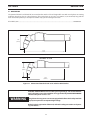
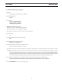
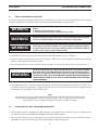
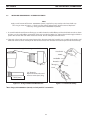
PT-31XL and PT-31XLPC
Plasma Arc Cutting Torches
Instruction Manual (GB)
0558005178
BE SURE THIS INFORMATION REACHES THE OPERATOR.
YOU CAN GET EXTRA COPIES THROUGH YOUR SUPPLIER.
CAUTION
These INSTRUCTIONS are for experienced operators. If you are not fully familiar with the
principles of operation and safe practices for arc welding and cutting equipment, we urge
you to read our booklet, “Precautions and Safe Practices for Arc Welding, Cutting, and
Gouging,” Form 52-529. Do NOT permit untrained persons to install, operate, or maintain
this equipment. Do NOT attempt to install or operate this equipment until you have read
and fully understand these instructions. If you do not fully understand these instructions,
contact your supplier for further information. Be sure to read the Safety Precautions before installing or operating this equipment.
USER RESPONSIBILITY
This equipment will perform in conformity with the description thereof contained in this manual and accompanying labels and/or inserts when installed, operated, maintained and repaired in accordance with the instructions provided. This equipment must be checked periodically. Malfunctioning or poorly maintained equipment
should not be used. Parts that are broken, missing, worn, distorted or contaminated should be replaced immediately. Should such repair or replacement become necessary, the manufacturer recommends that a telephone
or written request for service advice be made to the Authorized Distributor from whom it was purchased.
This equipment or any of its parts should not be altered without the prior written approval of the manufacturer.
The user of this equipment shall have the sole responsibility for any malfunction which results from improper
use, faulty maintenance, damage, improper repair or alteration by anyone other than the manufacturer or a service facility designated by the manufacturer.
72
TABLE OF CONTENTS
Section / Title
Page
1.0
Safety Precautions . . . . . . . . . . . . . . . . . . . . . . . . . . . . . . . . . . . . . . . . . . . . . . . . . . . . . . . . . . . . . . . . . . . . . . . . . . . . . . . . . . 75
2.0
Description . . . . . . . . . . . . . . . . . . . . . . . . . . . . . . . . . . . . . . . . . . . . . . . . . . . . . . . . . . . . . . . . . . . . . . . . . . . . . . . . . . . . . . . . .
2.1 Description. . . . . . . . . . . . . . . . . . . . . . . . . . . . . . . . . . . . . . . . . . . . . . . . . . . . . . . . . . . . . . . . . . . . . . . . . . . . . . . . . . . .
2.2 Accessories . . . . . . . . . . . . . . . . . . . . . . . . . . . . . . . . . . . . . . . . . . . . . . . . . . . . . . . . . . . . . . . . . . . . . . . . . . . . . . . . . . . .
2.3 Technical Data (required by CE) . . . . . . . . . . . . . . . . . . . . . . . . . . . . . . . . . . . . . . . . . . . . . . . . . . . . . . . . . . . . . . . .
3.0
Installation / Operation. . . . . . . . . . . . . . . . . . . . . . . . . . . . . . . . . . . . . . . . . . . . . . . . . . . . . . . . . . . . . . . . . . . . . . . . . . . . . . .81
3.1 Torch / Consumables Inspection . . . . . . . . . . . . . . . . . . . . . . . . . . . . . . . . . . . . . . . . . . . . . . . . . . . . . . . . . . . . . . . .81
3.2 Disassembly of Torch - Removing Consumables. . . . . . . . . . . . . . . . . . . . . . . . . . . . . . . . . . . . . . . . . . . . . . . . . .81
3.3 Installing Consumables - Assembly of Torch . . . . . . . . . . . . . . . . . . . . . . . . . . . . . . . . . . . . . . . . . . . . . . . . . . . . 82
4.0
Maintenance. . . . . . . . . . . . . . . . . . . . . . . . . . . . . . . . . . . . . . . . . . . . . . . . . . . . . . . . . . . . . . . . . . . . . . . . . . . . . . . . . . . . . . . . 83
4.1 Maintenance . . . . . . . . . . . . . . . . . . . . . . . . . . . . . . . . . . . . . . . . . . . . . . . . . . . . . . . . . . . . . . . . . . . . . . . . . . . . . . . . . . 83
4.2 Repositioning Torch Switch . . . . . . . . . . . . . . . . . . . . . . . . . . . . . . . . . . . . . . . . . . . . . . . . . . . . . . . . . . . . . . . . . . . . 83
5.0
Replacement Parts . . . . . . . . . . . . . . . . . . . . . . . . . . . . . . . . . . . . . . . . . . . . . . . . . . . . . . . . . . . . . . . . . . . . . . . . . . . . . . . . . .
5.1 Definitions . . . . . . . . . . . . . . . . . . . . . . . . . . . . . . . . . . . . . . . . . . . . . . . . . . . . . . . . . . . . . . . . . . . . . . . . . . . . . . . . . . . .
5.2 Ordering . . . . . . . . . . . . . . . . . . . . . . . . . . . . . . . . . . . . . . . . . . . . . . . . . . . . . . . . . . . . . . . . . . . . . . . . . . . . . . . . . . . . . .
5.3 PT-31XL and PT-31XLPC Replacement Parts . . . . . . . . . . . . . . . . . . . . . . . . . . . . . . . . . . . . . . . . . . . . . . . . . . . . .
73
77
77
78
79
85
85
85
85
TABLE OF CONTENTS
74
SECTION 1
1.0
SAFETY PRECAUTIONS
Safety Precautions
Users of ESAB welding and plasma cutting equipment have the ultimate responsibility for ensuring that anyone
who works on or near the equipment observes all the relevant safety precautions. Safety precautions must meet
the requirements that apply to this type of welding or plasma cutting equipment. The following recommendations
should be observed in addition to the standard regulations that apply to the workplace.
All work must be carried out by trained personnel well acquainted with the operation of the welding or plasma
cutting equipment. Incorrect operation of the equipment may lead to hazardous situations which can result in
injury to the operator and damage to the equipment.
1. Anyone who uses welding or plasma cutting equipment must be familiar with:
- its operation
- location of emergency stops
- its function
- relevant safety precautions
- welding and / or plasma cutting
2. The operator must ensure that:
- no unauthorized person stationed within the working area of the equipment when it is started up.
- no one is unprotected when the arc is struck.
3. The workplace must:
- be suitable for the purpose
- be free from drafts
4. Personal safety equipment:
- Always wear recommended personal safety equipment, such as safety glasses, flame proof
clothing, safety gloves.
- Do not wear loose fitting items, such as scarves, bracelets, rings, etc., which could become
trapped or cause burns.
5. General precautions:
- Make sure the return cable is connected securely.
- Work on high voltage equipment may only be carried out by a qualified electrician.
- Appropriate fire extinquishing equipment must be clearly marked and close at hand.
- Lubrication and maintenance must not be carried out on the equipment during operation.
75
SECTION 1
WARNING
SAFETY PRECAUTIONS
WELDING AND PLASMA CUTTING CAN BE INJURIOUS TO YOURSELF AND
OTHERS. TAKE PRECAUTIONS WHEN WELDING OR CUTTING. ASK FOR
YOUR EMPLOYER’S SAFETY PRACTICES WHICH SHOULD BE BASED ON
MANUFACTURERS’ HAZARD DATA.
ELECTRIC SHOCK - Can kill.
- Install and earth (ground) the welding or plasma cutting unit in accordance with applicable standards.
- Do not touch live electrical parts or electrodes with bare skin, wet gloves or wet clothing.
- Insulate yourself from earth and the workpiece.
- Ensure your working stance is safe.
FUMES AND GASES - Can be dangerous to health.
- Keep your head out of the fumes.
- Use ventilation, extraction at the arc, or both, to take fumes and gases away from your breathing zone
and the general area.
ARC RAYS - Can injure eyes and burn skin.
- Protect your eyes and body. Use the correct welding / plasma cutting screen and filter lens and wear
protective clothing.
- Protect bystanders with suitable screens or curtains.
FIRE HAZARD
- Sparks (spatter) can cause fire. Make sure therefore that there are no inflammable materials nearby.
NOISE - Excessive noise can damage hearing.
- Protect your ears. Use earmuffs or other hearing protection.
- Warn bystanders of the risk.
MALFUNCTION - Call for expert assistance in the event of malfunction.
READ AND UNDERSTAND THE INSTRUCTION MANUAL BEFORE INSTALLING OR OPERATING.
PROTECT YOURSELF AND OTHERS!
76
SECTION 2
DESCRIPTION
2.1 DESCRIPTION
The patented PT-31XL and PT-31XLPC are manual torches with a 75° head designed for use with several plasma arc cutting
packages using clean, dry air as the plasma gas. The service lines are 4.5, 7.6 or 15.2 meters (15, 25 or 50 feet) long and the
torch is rated to operate up to 50 amperes at 100% duty cycle for cutting most metals.
PT-31XLPC, 7.6m ................................................................................................................................................................................... 0558005393
PT-31XL - 75° Torch
2 1/4"
(57mm)
5 1/4"
(133mm)
PT31XLPC - 75° Torch
2 7/8"
(73mm)
5 1/4"
(133mm)
Figure 2-1 Dimensional Data for the PT-31XL and PT-31XLPC Torches
ELECTRIC SHOCK CAN KILL.Plasma cutting uses high voltage. Skin contact with the
torch, the power source, the workpiece or any grounded object MUST BE AVOIDED
whenever the power source is on.
WARNING
Using the torch on any power source not equipped with a flow switch safety interlock
may expose operator to unexpected high voltage.
Before beginning operation of the torch, refer to the safety precautions and operating instructions.
77
SECTION 2
DESCRIPTION
2.2 ACCESSORIES
A spare parts kit is recommended for maintaining the torch with minimum downtime. A spare parts kit is supplied with each
plasma cutting package.
PowerCut-650, Spare Parts Kit .....................................................................................................................0558005392
PCM-500i ONLY and as an option on HandyPlasma 550
35/40A XT Spare Parts Kit (Extended Life) ................................................................................................................................................ 21980
PCM-500i, PowerCut-650, HandyPlasma 550 and HandyPlasma 380
30/40A Standard Spare Parts Kit (High Performance) .............................................................................................................0558003301
Note
The high performance kit (0558003301) is the preferred kit and is included with all of the above
referenced plasma cutting systems.
Table 2-1 Contents of Spare Parts Kits:
Description
Heat Shield
Heat Shield, Long "CE"
30/40 amp High
Performance Nozzle
35/40 amp Extended
Life Nozzle
Nozzle, 50 amp
Swirl Baffle
Electrode
O-ring
Lubricant (0.25 ounce)
P/N (optional P/N)
20282
0558000509 (36284)
* PT-31XL and PT-31XLPC Spare Parts Kits P/Ns
P/N 21980 P/N 0558003301 P/N 0558003464 P/N 0558003462 P/N 0558005392
35/40A
30/40A
50A / HP-50
35A / Caddycut 40A / PC-650
(Europe only)
(Europe only)
(Europe only)
1
0558000512 (20860)
0558000508 (21008)
0558000513 (20861)
0558000506 (20463)
0558000507 (20862)
0558000514 (950790)
0558000443 (17672)
1
1
1
3
3
1
2
1
2
1
1
1
3
3
1
3
1
3
1
2
1
2
1
* Also see Tables 5-2 and 5-3.
Plasma Flow Measuring Kit:
This valuable troubleshooting tool allows measurement of
the actual plasma gas flow through the torch ............................................................................................................................................ 0558000739
Torch Guide Kit:
This complete kit, in a rugged plastic carrying case, includes
attachments for circle and straight line cutting on ferrous and
non-ferrous metals.
Deluxe, 1-3/4" - 42" (44.5mm-1060mm) Radius .............................................................................................................................................................................. 0558003258
Basic, 1-3/4” - 28” (44.5mm-710mm) Radius .................................................................................................................................................................................... 0558002675
78
SECTION 2
DESCRIPTION
2.3 TECHNICAL DATA (required by CE)
a. Process:
Manual torch used for plasma arc cutting
b. Method of guidance:
Manual
c. Voltage class:
M (113v peak to 400v peak)
Striking voltage: 8000 VAC
Stabilizing voltage: 200 VDC
d. Maximum rated current: 50 amps
Maximum current at 100% duty cycle: 50 amps
Type gas: 120 I/min. at 5.5 bar (254 cfh at 80 psi)
e. Max. and min. gas pressure at inlet: 4.8 to 5.9 bar (70 to 86 psi)
f. Type of cooling:
Air
g. Rating of auxiliary electrical control in torch:
N/A
h. Requirements for connection of torch:
Wrenches and screwdriver
i. Essential information about safe operation of torch:
Refer to all safety precautions in manual
j. Essential information about safe operation of the plasma cutting torch and the functioning of interlocking and safety
devices:
Meets requirements by means of pneumatic interlock safety system. The interlocking device deenergizes the torch
when parts, particularly protective cone, are removed to expose electrode connection. For the interlocking device
to function properly, the torch electrode must remain in the protective cone. Do not attempt to install the electrode
into the torch without first placing it in proper position (with the other parts) within the protective cone.
k. Type of plasma cutting power source that can form a safe system with the plasma cutting torch:
PCM-500i, PowerCut 650, HandyPlasma 550, HandyPlasma 380, HandyPlasma 50 and Caddycut.
I. Plasma cutting ability:
See Graphs 2-1a and 2-1b on following page:
79
SECTION 2
DESCRIPTION
100
Speed, in/min
Speed, mm/min
80
60
40
20
0
.125
0
.250
.375
.500 .625
Steel Thickness, in.
Steel Thickness, mm
4064
160
3556
140
3048
120
2540
Speed, in/min
Speed, mm/min
Graph 2-1a 35 Amp Cutting Parameters
50A
2032
1524
100
60
1016
40
508
254
0
20
10
0
0
3
6
10
13
16
19
50A
80
0
.125
Steel Thickness, mm
.250 .375 .500 .625 .750
Steel Thickness, in.
Graph 2-1b 50 Amp Cutting Parameters
80
SECTION 3
3.1
INSTALLATION / OPERATION
TORCH / CONSUMABLES INSPECTION
For detailed installation and operation follow all torch instructions in the plasma system manual packed with your cutting
package. DO NOT install or attempt to operate this torch without following those instructions first.
WARNING
Conditions under which extra precautions are to be observed during plasma
cutting:
1. Refer to general warnings in manual.
2. Do not cut closed containers. An explosion may result.
WARNING
Before inspecting or changing consumables make sure power switch on the power
source is in the OFF position and primary input power is deenergized.
WARNING
BE SURE to install the swirl baffle in the torch. Failure to do so would allow the
nozzle (tip) to contact the electrode. This contact would permit high voltage to
be applied to the nozzle. Your contact with the nozzle or workpiece could then
result in serious injury or death by electric shock.
1. Periodically check the heat shield, electrode, nozzle, and swirl baffle. Replace if worn or damaged.
2. The power cable assembly should be inspected periodically. If there are any cuts through the protective sheath or if gas
leaks are noted, replace the damaged assembly.
3. Do not continue to use torch if the electrode erodes to a length shorter than 16mm (0.63 inch) as shown in Figure 3-1.
WARNING
The torch head contains a gas flow check valve that acts in conjunction with the
flow switch and circuitry within the power source. This system prevents the torch
from being energized with high voltage if the torch switch is accidentally closed
when the heat shield is removed. ALWAYS REPLACE TORCH WITH THE APPROPRIATE
TORCH MANUFACTURED BY ESAB SINCE IT ALONE CONTAINS ESAB'S PATENTED
SAFETY INTERLOCK.
4. The gas flow check valve is part of the safety interlock and is permanently assembled in the torch head. The head must
be replaced if this valve malfunctions. The light spring force used to close the ball check can be felt by pushing on the
electrode when assembling the front end components.
Note
The electrode seat comes assembled in the front end of the torch. When using the XT consumables, make
sure the plunger, P/N 0558000511 (20324), is installed under the seat. If missing, remove seat and install
plunger. Make sure seat is tightened firmly with a wrench but do NOT overtighten.
3.2
DISASSEMBLY OF TORCH - REMOVING CONSUMABLES
1. To disassemble the front end, hold the torch with the shield in an upright position as shown in Figure 3-2. This will prevent
the nozzle, electrode, and swirl baffle from falling free when the shield is removed.
2. If the torch is fixed and cannot be rotated upward, the alternate method of disassembly is to disassemble the electrode,
swirl baffle and nozzle as above being careful not to damage them by letting them fall.
81
SECTION 3
3.3
INSTALLATION / OPERATION
INSTALLING CONSUMABLES - ASSEMBLY OF TORCH
Note
Apply a small amount of lubricant - 0558000443 (17672), supplied in spare parts kit, to the heat shield or to
the o-ring as shown in Figure 3-1. Check o-ring for damage whenever the shield is removed. Replace if
necessary. O-ring part number is 0558000514 (950790).
1. To assemble with the torch front end facing up, assemble electrode, swirl baffle, tip and heat shield in that order as shown
in Figure 3-2. The swirl baffle is symmetrical and it can be positioned either way. Tighten heat shield snugly to hold the
parts in firm contact with each other and the torch head. Do not overtighten the heat shield.
2. If the torch is fixed and cannot be rotated upward, the alternate method of assembly is to assemble the electrode, swirl
baffle and nozzle as above and drop them into the heat shield. Then thread the heat shield upward into the torch body.
Lubricant can be applied to O-ring or Heat Shield
Heat Shield
Nozzle
Swirl Baffle
Electrode
*Plunger
Seat
Torch
"XT" Electrode
Replace electrode when end
wears to 16mm (0.63") long.
16mm (0.63")
Minimum
Figure 3-1 O-ring and Electrode Maintenance
Figure 3-2 Front End Assembly
*Note: Plunger, P/N 0558000511 (20324), used only with "XT" consumables.
82
SECTION 4
MAINTENANCE
4.1 MAINTENANCE
The power cable and switch leads in the service line should be inspected periodically. If there are any cuts through the protective sheath or if gas leaks are noted, replace the damaged component.
WARNING
4.1.1
Before any maintenance is attempted on this torch, make sure the POWER SWITCH
on the power source is in the OFF position and the PRIMARY INPUT POWER is
DEENERGIZED.
Disassembly of Service Line (refer to Figure 4-1)
1.
Lay the line out straight.
2.
Pull flex support back and remove the tape from around the switch lead splices.
3.
Free the switch by cutting the leads close to the splices.
4.
Replacement switches have extra long leads to make up for any loss due to cutting.
5.
Remove the rubber boot from the inlet end of the cable.
6.
Remove the tape that secures the sheath at each end.
7.
Pull the sheath off the cable (over small fitting at torch end).
Note
The switch leads wrapped around the power cable are secured with tape several places along the cable.
WARNING
8.
BE SURE to loosen fittings using 2 wrenches during disassembly. Failure to do so
could result in serious injury to the operator.
The leads, switch cord plug, and strain relief can now be removed. See Figure 4-1, Step 3.
CAUTION
DO NOT remove the white tape that forms a band around the power cable at each
end. The sheath is taped to the cable in front of the band which acts as a shoulder
to prevent the sheath from sliding back on the cable. Replacement cables have
this tape in place.
If the switch leads are to be replaced, replace with 16 AWG STRANDED COPPER,
600- VOLT, 90° C (194° F) INSULATED WIRE.
9.
4.2
Reassemble in reverse order.
Repositioning Torch Switch
In some applications it is more convenient for the troch switch to be positioned 180 degrees from current configuration.
To reposition the switch on the torch, slide the flex support back, remove the tape securing the spliced leads to the power
cable, reposition switch, retape the leads, and pull the flex support back in place. See Figure 4-1.
Note
A thin film of silicone lubricant P/N 0558000443 (17672), supplied with the spare parts kit, applied inside of
the flex support will ease the assembly of this part.
83
SECTION 4
WARNING
MAINTENANCE
BE SURE to tighten fittings securely using 2 wrenches during reassembly. (Factory
recommended torque is 3.39 n-m or 30 in-lbs). Failure to do so could result in serious injury to the operator.
1 Pull flex support back. Remove
tape holding splices.
2
Unscrew handle and
power cable from head
Slide switch and band from handle.
Snip leads at splice to replace
switch.
3
Figure 4-1 Power Cable and Switch Disassembly Sequence
84
SECTION 5
5.1
REPLACEMENT PARTS
Definitions
"XT" Consumables - Used with currently produced product (HandyPlasma 380, HandyPlasma 550, PCM-500i, PowerCut
650, Caddycut and HandyPlasma-50), and older products dating back to 1990.
Standard Consumables / Heavy Duty Consumables - Available for support of pre-1990 year machines (PCM-32i,
PCM-50 and PCM-31) and consumables configurations. These are the original consumables designed for the torch.
High Performance Nozzle - Gives maximum cutting thickness and speed capability.
Extended Life Nozzle - Gives extended nozzle life at the expense of top end cutting thickness and speed capability.
5.2
Ordering
To ensure proper operation, it is recommended that only genuine ESAB parts and products be used with this equipment.
The use of non-ESAB parts may void your warranty.
Have the plasma power source model number and serial number handy if there are any questions concerning required
parts.
Replacement parts may be ordered from your ESAB Distributor.
Be sure to indicate any special shipping instructions when ordering replacement parts.
Refer to the Communications Guide located on the back page of this manual for a list of customer service phone numbers.
5.3
PT-31XL and PT-31XLPC Replacement Parts
1.
The PT-31 torch is used on several different cutting packages which require different torch trigger connection configurations as shown in Figure 5-1 and Table 5-1.
2.
The PT-31 torch is adaptable to standard, heavy duty or XT consumables to meet specific cutting applications. See
Subsections 5.3.1, 5.3.2 and 5.3.3.
3.
Individual consumable parts can be ordered as needed if spare parts kits do not fit current needs.
In most cases, it is recommended that you order the same consumable parts that were shipped with your plasma cutting
system.
85
SECTION 5
REPLACEMENT PARTS
(2) SPLICES (Supplied with Switch)
SWITCH - 0558000818 (18224)
FLEX SUPPORT - 0558000710 (18225)
SWITCH BAND
0558000699 (18207)
SHEATH
0558000583 (19675) - 4.6m (15')
0558000791 (18320) - 7.6m (25')
0558000792 (19026) - 15.2m (50')
750 HEAD - 0558000790 (20072)
(Includes O-ring and Seat)
HANDLE - 0558000796 (18208)
5/8 X 18 L.H.
POWER CABLE
0558005148 (19672) - 4.6m (15')
0558000795 (18221) - 7.6m (25')
0558005146 (19028) - 15.2m (50')
STRAIN RELIEF
0558000794 (18226)
O-ring - 0558000514 (950790)
(included with head)
BOOT - 0558000793 (49N83)
PLUG - 2062336
Configuration 3
PLUNGER- 0558000511 (20324)
(used only with "XT" consumables)
Configuration 1
SEAT - 0558000510 (19679)
(Included with Head)
Figure 5-1 PT-31XL Torch Parts and Configurations
86
87
NOZZLE 30-40 AMP 0558000512 (20860)
3/8-24UNF-2A
Figure 5-2 PT-31XLPC Torch Parts and Configurations
POWER CABLE
0558003323
SPLICE - 0558004020 (674520)
HANDLE - 0558000796 (18208)
FLEX SUPPORT - 0558000710 (18225)
Configuration 2
PLUNGER - 0558000511 (20324)
O-RING - 0558000514 (950790)
HEAT SHIELD - 20282
SWITCH - 0558000818 (18224)
BAND SWITCH - 0558000699 (18207)
BODY ASSEMBLY 75° - 0558000790 (20072)
ELECTRODE - 0558000507 (20862)
BAFFLE SWIRL - 0558000506 (20463)
PT-31XLPC Torch Assembly (0558003183) used with Powercut-650 only
SECTION 5
REPLACEMENT PARTS
SECTION 5
Configuration #
1
2
REPLACEMENT PARTS
Plasma Cutting
System
Complete
Torch Assembly
Installed Consumables
20084 - 4.6m (15') lines
20080 - 7.6m (25') lines
20082 - 15.2m (50') lines
Seat and o-ring. Consumables and plunger not
included.
21985 - 7.6m (25') lines
30A / 40A high performance "XT" consumables,
standard heat shield P/N 20282, seat, o-ring and
plunger.
PCM 500i, Handy
Plasma-550 (Asia)
0558005393
7.6m (25') lines
30A / 40A high performance "XT" consumables,
standard heat shield P/N 20282, seat, o-ring and
plunger.
Powercut-650
30A / 40A high performance "XT" consumables,
standard heat shield P/N 20282, seat, o-ring and
plunger.
0558004482
4.6m (15') lines
NOTE: When ordering the PT-31XL torch
assembly for use on the HandyPlasma-380,
Female Torch Connector P/N 0558004947 shown
below must also be ordered.
HandyPlasma-380
0558001466
4.6m (15') lines
30A / 40A high performance "XT" consumables,
long heat shield P/N 0558000509 (36284), seat,
o-ring and plunger.
CaddyCut
(Europe)
0558004498
7.6m (25') lines
30A / 40A high performance "XT"
consumables,standard heat shield P/N 20282,
seat, o-ring and plunger.
HandyPlasma-550
(North America)
0558003467
7.6m (25') lines
30A / 40A high performance "XT" consumables,
long heat shield P/N 0558000509 (36284), seat,
o-ring and plunger.
HandyPlasma-50
(Europe)
3
Table 5-1 PT-31 Replacement Torch and Torch Parts
88
SECTION 5
5.3.1
REPLACEMENT PARTS
Standard Consumables
These consumable parts will give good cut quality on light to medium thick metals when used within the recommended cutting range of the plasma power source. The reversible electrode design gives extra electrode life and
enables the safety interlock for operator safety.
The use of other than genuine ESAB consumables and replacement parts can cause personal
injury and / or damage to the equipment.
WARNING
ESAB does not warrant parts for its equipment which are not furnished by ESAB. The use of
parts that are not furnished by ESAB does not automatically void ESAB's warranties for its
equipment. Any obligations otherwise arising from ESAB's warranty will be voided if, but only
if, the design, manufacture or composition of parts or components not supplied by ESAB are
a material cause of the malfunction or poor performance of (or damage to) the equipment.
Standard
P/N 18205
ELECTRODE
BAFFLE
P/N 18785
"White”
4 Holes
5 Stakes
P/N 19667
15 Amp
4 Stakes
P/N 18866
30 Amp
P/N 18820
50 Amp
(Original Style )
1-21/64"
(33.7mm)
NOZZLE
(TIP)
1-1/8"
(28.6mm)
0.155"
(3.9mm)
HEAT SHIELD
P/N 20282 Standard
(Lite Blue)
P/N 18844
Ceramic
(White)
Figure 5-3 Torch Front End Standard Consumables
89
SECTION 5
5.3.2
REPLACEMENT PARTS
Heavy Duty Consumables
The larger electrode diameter increases the electrode mass to provide improved cooling and reduced wear on
medium to heavy cutting applications when correctly used within the recommended cutting range of the plasma
power source. The reversible electrode design gives extra electrode life and enables the safety interlock for operator safety.
The use of other than genuine ESAB consumables and replacement parts can cause personal
injury and / or damage to the equipment.
WARNING
ESAB does not warrant parts for its equipment which are not furnished by ESAB. The use of
parts that are not furnished by ESAB does not automatically void ESAB's warranties for its
equipment. Any obligations otherwise arising from ESAB's warranty will be voided if, but only
if, the design, manufacture or composition of parts or components not supplied by ESAB are
a material cause of the malfunction or poor performance of (or damage to) the equipment.
Heavy Duty
P/N 19683
1-1/32"
(26.2mm)
0.200"
(5.1mm)
ELECTRODE
P/N 0558000506 (20463)
"Pink”
6 Holes
BAFFLE
6 Stakes
NOZZLE
(TIP)
No
Cross
P/N 20079 Hatch
50 Amp
P/N 19682
30 Amp
HEAT SHIELD
P/N 20282 Standard
(Lite Blue)
Figure 5-4 Torch Front End Heavy Duty Consumables
90
SECTION 5
5.3.3
REPLACEMENT PARTS
“XT” Consumables
The “XT” electrode and nozzle design extends the metal cutting thickness range and improves cut speed and
edge quality for production plasma cutting applications. The torch safety interlock is enabled through the “nonconsumable” plunger installed behind the removable seat in the torch head.
The use of other than genuine ESAB consumables and replacement parts can cause personal
injury and / or damage to the equipment.
WARNING
ESAB does not warrant parts for its equipment which are not furnished by ESAB. The use of
parts that are not furnished by ESAB does not automatically void ESAB's warranties for its
equipment. Any obligations otherwise arising from ESAB's warranty will be voided if, but only
if, the design, manufacture or composition of parts or components not supplied by ESAB are
a material cause of the malfunction or poor performance of (or damage to) the equipment.
“XT"
“Extended Thickness”
PLUNGER
(Assembles between
seat and head)
P/N 0558000511 (20324)
P/N 0558000507 (20862)
ELECTRODE
BAFFLE
P/N 0558000506 (20463)
"Pink”
6 Holes
30/40 Amp P/N 0558000512 (20860)
(HIGH PERFORMANCE)
NOZZLE
(TIP)
35/40 Amp P/N 0558000508 (21008)
(EXTENDED LIFE)
50 Amp P/N 0558000513 (20861)
HEAT SHIELD
P/N 20282 Standard (Lite Blue)
P/N 0558000509 (36284) CE (Long Heat Shield) Version
Figure 5-5 Torch Front End "XT" Consumables
91
SECTION 5
REPLACEMENT PARTS
Standard Consumables Kits
P/N 20464
50 Amp
(note 3)
P/N 18231
30 Amp
(note 3)
Description
P/N (Qty)
P/N (Qty)
Heat Shield
Nozzle
Electrode
Seat
20282 (3)
20079 (5)
19683 (5)
0558000510
(19679) (1)
0558000514
(950790) (5)
0558000506
(20463) (3)
20282 (2)
18866 (4)
18205 (4)
0558000510
(19679) (1)
0558000514
(950790) (5)
18785 (1)
0558000443
(17672) (1)
—
0558000443
(17672) (1)
—
O-Ring
Swirl Baffle
Lubricant
(1 oz.)
Plunger
Table 5-2 Contents of PT-31XL and PT-31XLPC Standard Consumables Spare Parts Kits
"XT" Consumables Kits
P/N 21051
50 Amp
(note 3)
P/N 21052
40 Amp
(note 3)
P/N 21980
P/N 0558003301
35 / 40 Amp 30/40 Amp
(note 2)
(note 1)
P/N 0558003464
50 Amp
(note 4)
P/N 0558003462 P/N 0558005392
35 Amp
40 Amp (CE)
(note 5)
(note 1)
Description P/N (Qty)
P/N (Qty)
P/N (Qty)
P/N (Qty)
P/N (Qty)
P/N (Qty)
P/N (Qty)
Heat Shield
20282 (2)
20282 (2)
20282 (1)
20282 (1)
Nozzle
0558000513
(20861) (4)
0558000507
(20862) (3)
—
—
0558000508
(21008) (4)
0558000507
(20862) (3)
—
—
0558000508
(21008) (3)
0558000507
(20862) (2)
—
—
0558000512
(20860) (3)
0558000507
(20862) (2)
—
—
0558000509
(36284) (1)
0558000508
(21008) (3)
0558000507
(20862) (2)
—
—
0558000509
(36284) (1)
0558000512
(20860) (3)
0558000507
(20862) (2)
—
—
0558000506
(20463) (1)
0558000506
(20463) (1)
0558000506
(20463) (1)
0558000506
(20463) (1)
0558000509
(36284) (1)
0558000513
(20861) (3)
0558000507
(20862) (3)
—
0558000514
(950790) (1)
0558000506
(20463) (1)
0558000506
(20463) (1)
0558000506
(20463) (1)
—
—
—
—
—
0558000443
(17672) (1)
0558000511
(20324) (2)
0558000511
(20324) (2)
—
0558000443
(17672) (1)
0558000511
(20324) (2)
—
—
—
Electrode
Seat
O-Ring
Swirl Baffle
Lubricant
(1 oz.)
Plunger
Table 5-3 Contents of PT-31XL and PT-31XLPC "XT" Consumables Spare Parts Kits
note 1 - for PCM-500i, PowerCut-650, HandyPlasma 550 and HandyPlasma 380
note 2 - for PCM-500i ONLY and as an option on HandyPlasma 550
note 3 - for older produced machines.
note 4 - HandyPlasma-50 for Europe
note 5 - Caddycut for Europe
92