1
Declaration of Conformity
EC - DECLARATION OF CONFORMITY
CE MARKING
We, the Manufacturer
SABINE, INC.
13301 NW US HIGHWAY 441
ALACHUA, FLORIDA USA
declare that the product
RECEIVER
SABINE MODEL SWM7000
Is in conformity with
Council Directive: 73/23/EEC and 89/336/EEC (EMC Directives)
Standards to which conformity is declared:
EN 60065: 2001
EN 55022: 1998 Class B
EN 50082-1: 1998
Manufacturer Signature: __________________________
April, 2003
Date: 28
__________
Doran Oster, President
Name: __________________________
1
Sabine 2.4 GHz Smart Spectrum® Wireless
E-SWM7000-OpGuide-031219.pmd - hto
Table of Contents
1. INTRODUCTION
1.1. Section Contents
3
3
2. PRODUCT VIEWS
2.1. Receivers
2.1.1. Front panel views
2.1.2. Back panel Views
2.2. Transmitters
2.2.1. Handheld
2.2.2. Beltpack
2.3. Components
4
4
4
4
5
5
5
5
3. QUICK SETUPS
3.1. Receiver & Transmitter Quick Setup
3.2. FBX Quick Setup
3.3. Tips for Good RF Performance
3.4. Common Sources of RF Interference
6
6
6
10
10
4. TRANSMITTER OPERATION
4.1. First step
4.2. Displays and Settings
4.2.1. LCD Display
4.2.2. Accessing Transmitter Controls
4.2.3. Adjusting Transmitter Settings
4.2.4. Transmitter Battery Management
12
12
12
12
13
14
15
5. RECEIVER OPERATION
5.1. LCD Display.
5.2. Parameter Control & LCD Display
5.2.1. One set of Controls for 1 or 2 Channels
5.2.2. Channel Select / Contrast Button.
5.2.3. Special LCD Display Messages.
5.3. RF Channel Select
5.4. Output Level
5.5. Receiver Antenna Placement
5.5.1. Multi-path Interference
5.5.2. Receiver & Antenna Placement Tips
18
18
20
20
20
21
21
21
22
22
22
6. MIC SUPERMODELING™
6.1. Introduction
6.2. Emulation Choices
6.3. Mic Modeling Front Panel Control
6.4. Future Microphone Modeling Choices
6.4.1. Mic Model Upgrade Instructions
24
24
24
24
25
25
7. FBX FEEDBACK EXTERMINATOR®
7.1. FBX Introduction
7.1.1. FBX Fixed Filters
7.1.2. FBX Dynamic Filters
7.1.3. Balancing Fixed & Dynamic Filters
7.1.4. FBX Filter Width
7.2. FBX Set Up
7.2. FBX Bypass Button
26
26
26
26
26
26
26
27
8. COMPRESSOR/LIMITER OPERATION
8.1. Basics of Compression
8.2. Using the Compressor
8.3. Suggested Compression Settings
8.3.1. Vocal Settings
8.3.2. Guitar Settings
8.3.3. Bass Guitar Settings
8.5. Release & Knee Settings
28
28
28
29
29
29
29
30
31
31
31
31
10. PROGRAM SAVE & RECALL
10.1. Saving a Preset
10.2. Loading a Preset
10.3. Naming a Preset
10.4. Power Off Memory
32
32
32
32
32
11. MULTIPLE SYSTEMS OPERATION
11.1. Overview
11.1.1. Multiple System Interference
11.1.2. Setup Complexity
11.2. Antenna Distribution Amplifier
11.3. Antenna Distribution Amplifier Connection
33
33
33
33
34
35
12. EXTENSION ANTENNAS
12.1. Overview
12.2. Antenna Cabling & Cable Loss
36
36
36
13. REMOTE CONTROL OPERATION
13.1. Overview
13.1.1. Single vs. Multiple Receiver Control
13.1.2 Features & Controls Added Software
13.1.3. Software Multiple Unit Control
13.2. Software Installation
13.2.1. Requirements & Recommendations
13.2.2. Connections
13.2.3. Installing the Software
13.3. Launching the software
13.3.1. Off-Line Edit/Demo
13.3.2. Connecting Receivers.
13.4. Remote Control Operation
13.4.1. Two Views, Two Sets of Controls
13.4.2. Menus, Icons & Hot Keys
38
38
38
38
40
40
40
40
41
41
41
41
42
42
42
14. TIPS & TROUBLESHOOTING
14.1. Tips for Maximum Performance
14.2. Troubleshooting
14.3. Common Sources of RF Interference
14.3.1 RF Sources
46
46
46
47
47
15. FBX THEORY & PRACTICE
15.1. Introduction to FBX®
15.2. The Advantages of FBX Filters
15.3. Parametric Filters and FBX
15.3.1. The FBX & True Mobility® Advantage
14.3.2. FBX Fixed & Dynamic Filters
14.3.3. FBX Filter Width
14.3.4. Who Benefits from FBX?
49
49
49
50
51
51
52
52
15. APPENDICES
53
Appendix A: Beltpack Connector Wiring Diagrams 53
Appendix B: Antenna System Diagrams
53
Appendix C: Specifications
54
Appendix D: Dip Switch Settings
55
Appendix E: Frequency Chart
55
Appendix F: Battery Endurance Tests (Typical)
56
Appendix G: Changing Audix Mic Capsules (SW70-H) 56
This operating guide written for USB enabled receivers using Sabine
SWM7000 Remote Control Software version 2.0 and above.
Sabine 2.4 GHz Smart Spectrum® Wireless
9. DE-ESSER
9.1. De-mystifying De-essers
9.2. The Sabine De-esser
9.3. Using the De-esser
2
16. CAUTIONS & WARRANTY
57
INDEX
59
Introduction
1. INTRODUCTION
Congratulations on purchasing a Sabine 2.4 GHz Smart Spectrum True Mobility™ Wireless System. True Mobility™
Wireless Systems give you all the built-in processing you need on every microphone, and offer unique and powerful
features unavailable with any other wireless microphone
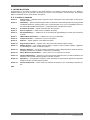
1.1. Section Contents
Section 2
Product Views — illustrates system components (front & back panel views, transmitters, accessory lists
and part numbers).
Section 3
Quick Setup — gives the Quick Setup procedures for Receiver & Transmitter Operation and using the FBX
Feedback Exterminator®. Note that there is also a quick-start label on top of your True Mobility receiver for
the Sabine FBX Feedback Exterminator®, Compressor/Limiter and De-Esser functions.
Section 4
Transmitter Operation — details transmitter setup and operation.
Section 5
Receiver Operation — details receiver installation and setup.
Section 6
Mic SuperModeling™ — explains the use of the Sabine Mic SuperModeling™ and lists the microphones
modeled.
Section 7
FBX Feedback Exterminator® — explains how to set up your FBX filters.
Section 8
Compressor/Limiter — explains the use of the Compressor.
Section 9
De-Esser — details operation of the adaptive De-Esser.
Section 10
Program Save & Recall — explains how to save and recall individual program settings.
Section 11
Multiple Systems — how multiple systems interface, computer control of multiple systems, suggestions
for maximizing the number of collocated systems.
Section 12
Extension Antennas — how to get maximum performance using a Sabine Extension Antennas (Antenna
Distribution Amplifier also available for multi-receiver installations).
Section 13
Sabine Remote Control Software — how to control up to 70 channels from one PC.
Section 14
Tips & Troubleshooting — gives tips on how to get the best performance from your Sabine Wireless, and
describes some possible operating problems and their solutions.
Section 15
Appendices — wiring diagrams, frequency charts, specifications, typical system diagrams and dip switch
settings for Sabine 2.4 GHz Wireless systems.
Section 16
Cautions & Warranties — states caution and warranty information for your True Mobility™ Wireless system.
Index
3
Sabine 2.4 GHz Smart Spectrum® Wireless
E-SWM7000-OpGuide-031219.pmd - hto
Product Views
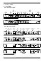
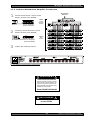
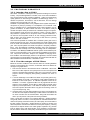
2. PRODUCT VIEWS
2.1. Receivers
2.1.1. Front panel views
Ch. A
Channel
Select,
Contrast
Antenna 1
Front Mount
Ch. A
Display
FBX
Mic DeModel esser
Compressor
Limiter
RF Ch. Output
Select Level
Program
Ch. B
Channel
Select,
Contrast
Ch. B
Display
Power
Antenna 2
Front Mount
Fig. 2a - SW72-NDR & SW72-R Two-channel Receivers
Fig. 2b - SW71-NDR & SW71-R One-channel Receivers
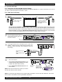
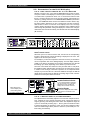
2.1.2. Back panel Views
AES3
Sync
Antenna 2
Digital Output Input
AC Power
& Fuses
RS485
Network
RS232
Serial
USB Port,
Dip Switches
Fig. 2c - SW72-NDR Two-channel Receiver w/Network & Digital Interface
Fig. 2d - SW71-NDR One-channel Receiver w/Network & Digital Interface
Fig. 2e - SW72-R Two-channel Receiver
Fig. 2f - SW71-R One-channel Receiver
Sabine 2.4 GHz Smart Spectrum® Wireless
4
Mic/Line Balanced
Output B
Mic/Line Balanced
Output A
Antenna 1
Product Views
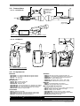
2.2.
Transmitters
Product
Views
2
Transmitter Controls
1 Select Button
2 Up Button
3 Down Button
ON ON ON
2.2.1. Handheld
OFF MUTE ON
SELECT
1
2.4 GHZ SMART SPECTRUM
3
Battery
LCD
Antenna
Battery
Switch
SWC-POWR
plug-in charger jack
Shown with cable
attached. Requires
assembly.
Fig. 2h - SWC70CL - SW70-HD3 & SW70-HD5 Mic Clip with Built-in Charger
2
1
2.2.2. Beltpack
ON ON ON
OFF MUTE ON
Antenna
SELECT
2.4 GHZ SMART SPECTRUM
3
Switch
TA4
Mini-XLR
Connector
SWC-POWR
plug-in
charger jack
Top view
Belt clip
Battery
Fig. 2i - SW70-T Beltpack Transmitter
2.3. Components
Receivers
Antennas
SW72-NDR: 2-Ch. Receiver w/Network & Digital Interface
SW71-NDR: 1-Ch. Receiver w/Network & Digital Interface
SW72-R: 2-Ch. Receiver
SW71-R: 1-Ch. Receiver
Microphones
SWT24L-TA4: Cardioid Lavalier Mic
SWT36L-TA4: Omni Lavalier Mic
SWT56W-TA4: Headworn Mic
SWT70BW-TA4: Voice Technologies Omni Headworn Mic (Black)
SWT70LW-TA4: Voice Technologies Omni Headworn Mic (Tan)
SWTVT50-TA4: Voice Technologies Miniature Omni Lavalier
SWT70G-TA4: Instrument Input w/cable
Transmitters
SW70-T: Beltpack Transmitter
SW70-HD3: Handheld Mic w/Dynamic Element (Audix OM3)
SW70-HD5: Handheld Mic w/Dynamic Element (Audix OM5)
SW70-HC: Handheld Mic w/Condenser Element
! ALKALINE BATTERY CAUTION ! Alkaline batteries must be one of following types:
SWA700: TNC Front to Rear Converter Kit (Set of 2)
SWA6SS: 2.4 GHz Antenna Distribution Amp for 6 systems
SWASS-EXT: 2.4 GHz Extension Antenna Kit (Set of 2)
SWAANT-2.4: 2.4 GHz Antennas (2)
SWATNC-N: RF Adaptor cable, Set of 4, TNC to NB
SWATNC-MCA: TNC Male Crimp Connector 2.4 GHz
Batteries
SWBC1: Rechargeable NiMH C for SW70-H
SWBAA2: Rechargeable NiMH AA set for SW70-T
Mic & Transmitter Accessories
SWCRJ45: RS485 Serial Connection Cable for ND Receivers
SWCCL: SW70-H Mic Holder w/Built-in Charger
SWCCL-2: Stage clip for SW70-H
SWCPOWR-EXT: Charger extension cable (3 meters)
SWCPOWR: Plug-in charger for SW70 Series Transmitters
SWC4P-TA4: Standard Mini-XLR Connector
Wind Screens available for all mics
NEDA: 14A
ANSI: 14A
IEC: LR14
— DO NOT USE RECHARGEABLE ALKALINE BATTERIES —
5
Sabine 2.4 GHz Smart Spectrum® Wireless
E-SWM7000-OpGuide-031219.pmd - hto
Quick Setups
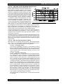
3. QUICK SETUPS
3.1. Receiver & Transmitter Quick Setup
Please read Section Four Transmitter Operation and Section Five Receiver Operation for a complete understanding of how to set up
your Sabine 2.4 GHz Smart Spectrum True MobilityTM System.
3.2. FBX Quick Setup
1
Transmitter range is 100
meters line-of-sight
Use Sabine’s SWASS-EXT
Extension Antenna Kit
when line-of-sight path is
not possible
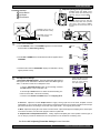
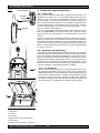
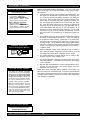
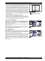
Be sure that all transmitters are off. Position receiver so that the antennas are within visual range of the
intended transmitter locations. Transmitter range is about 100 meters, but structural objects in the transmission
path can reduce that range. For best results, maintain a line-of-sight path between receiver antennas and transmitters (see Section 12). Use the TNC Rear-to-Front Kit (SWA700) included with the receiver to move antennas
to front if necessary. See Appendix B for more information on multiple-system connection.
2
Turn the OUTPUT LEVEL of the 2.4
GHz receiver and mixer gain to the
minimum settings.
3
Connect the output (¼-inch or XLR jack) of your 2.4 GHz True
MobilityTM receiver to the mic or line input of your mixer or amplifier (the receiver output gain can be adjusted to match the
mixer input).
Mixer Balanced Input
(XLR)
Mixer Unbalanced Input
(TRS)
4
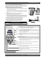
1. Turn on the receiver.
2. Tap the Channel Select/Contrast button to edit
a receiver channel. (Not necessary on 1-channel SW71-R & SW71-NDR receivers).
RF Channel
Selector
3. Turn the RF Channel Selector knob to the desired channel.
NOTE: Dual channel receivers will not allow you to select
the same RF channel for both channels.
Channel Select/
Contrast button
(selects receiver
channel to edit)
Power Switch
NOTE: Front panel RF Signal display will only register Sabine transmitters. It will not show RF interference. Use the RF
Scan function in the software to scan for potential RF interference.
Sabine 2.4 GHz Smart Spectrum® Wireless
6
Quick Setups
Beltpack Opening/Closing Instructions
Transmitter Controls
To Open: Press down firmly on Battery Door Handle and slide away from
LCD, then swing up and back.
1 Select Button
2 Up Button
3 Down Button
BATTERY
DOOR
HANDLE
To Close: Swing door down, flush with
transmitter body. Slide door up toward
LCD. Push in and up firmly on Battery
Door Handle with thumb until door lip
catches.
2
ON ON ON
OFF MUTE ON
To Open: Swing door up
from indented area on body.
SELECT
2.4 GHZ SMART SPECTRUM
1
2
1
3
To Close: Swing door
down until it latches.
ON ON ON
OFF MUTE ON
SELECT
2.4 GHZ SMART SPECTRUM
5
3
1. Turn on the transmitter.
2. Use the SELECT button until CHANNEL appears in the LED. NOTE:
the transmitter is muted during editing.
SELECT
3. Use the UP or DOWN button until the desired channel appears above
CHANNEL.
4. Check that the receiver’s RF SIGNAL display now indicates a strong
signal (at least 3 bars).
6
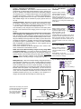
Gain Adjustment Settings
1. Transmitter (PAD Adjustment). Adjust the Transmitter PAD setting if
last segment of the Transmitter or Receiver Audio Level Meter lights up
often, or remains on when mic or beltpack is used.
Adjust PAD setting so that
Receiver Audio Level Meter
stays out of the clipping
zone (last segment)
1. Use the Transmitter Select button to scroll through functions
until PAD flashes in the Transmitter LCD.
2. Use the Up or Down buttons to select the desired setting. Selection is stored after 3 seconds of inactivity.
3. Check to see if Audio Level Meter stays out of Clipping Zone
2. Receiver. Adjust the receiver Output Level to supply a strong input level to the mixer, amplifier or active
loudspeaker. If your receiver output is connected to a microphone level input on the mixer, keep the receiver output
gain lower than when connecting to a line level mixer input. NOTE: -10 is a good place to start.
3. Mixer. Adjust the output gain of the mixer so that the mixer output meters approach clipping when all the inputs
to the mixer are active, and the audio program reaches its peak level.
4. Amplifier/active loudspeaker/crossover. Finally, adjust the amplifier gain control (and/or crossover gain, if
one is used) to provide the desired level of sound pressure in the auditorium or listening area.
See Section 4.2.3 Adjusting Transmitter Settings for more information.
7
Sabine 2.4 GHz Smart Spectrum® Wireless
E-SWM7000-OpGuide-031219.pmd - hto
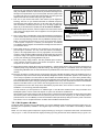
Quick Setups
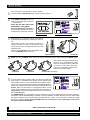
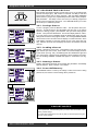
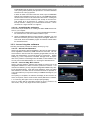
Place microphone and speakers in primary position.
Press and hold the SETUP button (Fig. 3d) on the receiver until the
1
2
LCD SETUP indicator (Fig. 3e)
flashes 4 times and SETUP stays lit
— then release it.
NOTE: DO NOT TALK INTO YOUR
SYSTEM while in Setup Mode.
Slowly raise the gain on the mixer or
amp until FBX eliminates the first few
feedback tones. With each new feedFig. 3d - FBX: SETUP
3
Fig. 3e - SETUP indicator flashing
back frequency, you will hear a short, quiet burst of
feedback that will disappear immediately as a filter is
set.
Pause raising the gain, and move the microphone to
another area where it will be used. Resume slowly
raising the mixer gain, until FBX eliminates a few more
feedback tones.
Repeat until the SETUP indicator automatically turns
off and the READY indicator comes on.
Mixer Channel
4
Location #1
NOTE: You may quit SETUP mode at any time prior to its automatic exit by simply pressing the READY button.
NOTE: When choosing microphone setup
locations, try to anticipate likely areas
where the microphone will be positioned
or moved to, or areas that may be especially prone to feedback problems (e.g.,
under an overhead speaker).
Location #2
5
Location #3
Location #4 (if necessary)
This will enable ready-to-operate status, but with fewer fixed FBX
filters in place. In the default factory setting, dynamic FBX filters will
still be held in reserve to catch and eliminate new feedback, regardless of how or when SETUP mode is exited. (See Section 14.3.2 for
details on the differences between fixed and dynamic FBX filters and
Section 13.4.2.1 for instructions on changing the balance of fixed
versus dynamic FBX filters using the Remote Control Software or
Appendix D for using the Dip Switches on the back of the receiver).
3.2.2. FBX Bypass
The BYPASS button (Fig. 3d) bypasses only the FBX filters, and not the additional signal processing (de-essing,
compression and Mic SuperModelingTM) available on the True MobilityTM Wireless Receiver. This is a useful button
that allows comparison of the sound quality when FBX filters are in place, to the sound with no filters (the quality
should be very similar). Before pressing BYPASS, take care to reduce your overall system gain so that you do
not release suppressed feedback!
FBX BYPASS CAUTION
Bypassing FBX filters may allow suppressed feedback to be released!
Sabine 2.4 GHz Smart Spectrum® Wireless
8
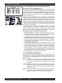
Quick Setups
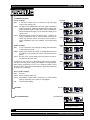
COMPRESSOR/LIMITER
Vocal Settings
Vocals
RATIO
A soft voice could be set to 2:1, whereas a loud voice might
require a ratio setting of 6:1.
THRESH
The higher the threshold setting, the more signal is required to
initiate compression. Ideally this should be set to reign in peak
levels, and allow signals of lower gain to pass uncompressed.
Threshold settings will depend on the nature and variety of the
signal source.
ATTACK
Short attack times usually work well for voice. However, too
strong a compression ratio, too low a threshold, and too fast an
attack may attenuate speech consonants, which provide important intelligibility cues to the audience, thus compromising
clarity.
Soft voice
Loud voice
Soft voice
Loud voice
THRESH
ATTACK
Short attack is better for vocals. Be careful not to
over attenuate speech consonants.
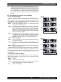
Guitar
Guitar Settings
RATIO
A high compression ratio (with gain makeup) will add sustain
to held notes and chords.
THRESH
Moving the threshold will change the audible thick/thinness of
the guitar tone, but generally you want to compress all the notes
played.
ATTACK
RATIO
RATIO
Less Sustain
THRESH
Be wary of too quick an attack, which may reduce the percussive attack of the guitar notes.
In general, be wary of too much gain makeup, and too high a compression ratio, which may make a noisy guitar amplifier more objectionable.
Ratio settings might range from 6 to 19:1, threshold variable, slower
attack, soft knee, output gain boosted slightly to significantly depending
on amount of compression.
More Sustain
Thinner sound
Thicker sound
ATTACK
Be wary of too quick an attack, which may reduce the
percussive attack of the guitar notes.
Bass Guitar Settings
RATIO
Set to 4:1
THRESH
Set to compress peaks only.
ATTACK
Quick attack, medium release, hard knee; (try various release
settings, depending on the speed of notes played).
GAIN
Output boosted slightly.
DE - ESSER
DE-ESSER
Less reduction
MIC SUPERMODELINGTM
More reduction
MIC SUPERMODELING
Scroll through available microphone settings. See
website for additional downloadable microphones.
NOTE: Mic SuperModelingTM is not available using beltpack transmitters.
NOTE:
Use these settings as a place from which to start, then adjust to your own satisfaction.
9
Sabine 2.4 GHz Smart Spectrum® Wireless
E-SWM7000-OpGuide-031219.pmd - hto
Quick Setups
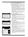
3.3. Tips for Good RF Performance
Antenna Placement Caution
As a general precaution, keep 2.4 GHz
cordless telephones, microwave ovens,
WLAN antennas and 2.4 GHz wireless
video camera transmitters twice the distance from your Sabine wireless microphone system antennas as that of your
Sabine 2.4 GHz transmitters.
•
Avoid potential sources of RF interference by performing a scan using
Sabine’s Remote Control Software., which will reveal the ambient RF level
in your area on each channel of your system. Please refer to Section 13.4.2.5.
for information on the RF Scan function, which will automatically determine
the best RF channels to use.
•
If you cannot perform a scan then proceed to use your system, beginning
with Channel 1. If you hear any RF “hits” or dropouts, then try another of the
70 available channels.
•
For best results, maintain line-of-sight from transmitter to receiver. Use
either front or rear panel antenna mounting to maintain line-of-sight.
•
Mount receiver antennas at 90 degrees to one another, leaning away at 45
degree angles, in the same plane.
•
When using multiple receivers, try to maintain at least 1 foot (30 cm) distance between antennas from different units. When such antenna spacing
proves difficult or impossible, we recommend using Sabine’s SWA6SS
Antenna Distribution Amplifier. The SWA6SS works with up to six receivers,
or 12 channels.
•
Maximize the distance between the receiver and light sources, such as
fluorescent bulbs or neon signs, which may emit very short-range, broadband interference.
•
Maximize the distance between transmitters and receivers and potential
sources of RF interference.
•
Maintain a minimum distance of at least 3 meters (10 feet) between transmitters and receivers or extension antennas. This can solve many anomalies.
•
Turn on your system one component at a time, beginning with the first
receiver.
•
Be careful not to set more than one transmitter to the same channel; each
paired transmitter and receiver should be set to unique corresponding
channels, until all channels are receiving clearly and cleanly.
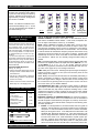
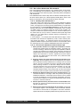
3.4. Common Sources of RF Interference
•
Microwave ovens: In the vast majority of situations, interference from
microwave ovens will not affect performance of your SWM7000 series microphone systems. Since barriers such as walls work to block interference, a microwave oven will likely present a problem only when located in
fairly close proximity within the same room as the wireless receiver (or
reception antenna). See caution at left.
•
Wireless Local Area Networks (WLANS): These computer network devices allow computers to connect via wireless devices that act as both
receivers and transmitters. These low-powered transceivers often have
selectable channels and can utilize the entire 2.4 GHz band. In general,
Sabine microphones should not be affected by these WLANS because
their spread spectrum technology does not present a problem for the Sabine
Smart SpectrumTM system. The Sabine wireless system will not interfere
with the WLAN. See caution at left.
•
2.4 GHz Cordless phones: These home telephones broadcast at very low
power and should not present interference problems for your Sabine wireless. This is especially true if the telephone uses spread spectrum technology. See caution at left.
•
Wireless Video Cameras: Certain wireless video cameras (X10, for example) use the 2.4 GHz band. These devices are also very low power and,
in general, should not present a problem when using the SWM7000 system. See Section 5 Receiver Operation for methods of optimizing clear
reception and minimizing interference. See caution at left.
In the event problems still arise, see Section 5 Receiver Operation for methods of optimizing clear reception and minimizing interference.
Sabine 2.4 GHz Smart Spectrum® Wireless
10
11
Sabine 2.4 GHz Smart Spectrum® Wireless
E-SWM7000-OpGuide-031219.pmd - hto
Transmitter Operation
TA4F connector
Fig. 4a
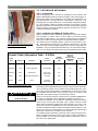
4. TRANSMITTER OPERATION
4.1. First step
Before you begin, let’s look at a few basics regarding your transmitters. The
handheld mic is ready to go — the microphone and transmitter are combined in one unit. To use the belt pack transmitter, however, you will have to
connect a lavalier or headworn microphone (or instrument pickup) to its
input. Sabine lavalier and headworn mics, and Sabine’s guitar/instrument
connector (SW70G-TA4) come equipped with the proper TA4F connector,
and are ready to plug right in. Be sure to line up the pins properly — do not
force the connector into the belt pack.
If you are using a different microphone with the Sabine belt pack, please
refer to the Appendix A for the required wiring plan. Failure to use the
proper wiring scheme may damage your mic or the belt pack, and void your
warranty.
Use the clip on the back of the belt pack transmitter to attach it to your belt or
clothing. The spring clip can be removed and reversed, to allow the transmitter and antenna to point either up or down in its clipped-on position. You
can also remove the clip if you choose to keep the transmitter in your pocket.
NOTE: it is essential that transmitters retain a line-of-sight relationship with
the receiver antennas.
External
Switch
Fixed
Antenna
Belt clip
4.2. Displays and Settings
Your Sabine 2.4 GHz Smart Spectrum handheld microphone and belt pack
transmitter have many powerful features, all of which are easily monitored
(using the transmitter LCD display) and adjusted. The controls and displays for both handheld and belt pack transmitters are identical in function,
though positioning differs (compare figures 4b & 4c). The LCD display and
one control switch are located on the exterior of the transmitters. A more
powerful set of recessed controls is located under the hinged access panel,
to prevent accidental or inappropriate alteration of settings.
5
2
4
ON ON ON
OFF MUTE ON
SELECT
2.4 GHZ SMART SPECTRUM
1
4.2.1. LCD Display
When the transmitter is first turned on, it shows an initial test screen (Fig.
4f), followed by the default screen (Fig. 4g). The LCD also reverts to this
default display within a few seconds after any programming changes are
made with the recessed controls. The default LCD display always shows
transmission channel, audio level, and battery voltage level; additional
information will appear to indicate important changes caused either by
user adjustments, or automatically as transmitter status changes.
6
3
Fig. 4b SW70H Handheld Control Setting Buttons
2
1
6
ON ON ON
OFF MUTE ON
SELECT
2.4 GHZ SMART SPECTRUM
4
3
Fig. 4c SW70T Transmitter Control Setting Buttons
1. Select Button
2. Up Button
3. Down Button
4. Programmable Control of External Switch
5. External Switch
6. Recessed control and battery compartments
Sabine 2.4 GHz Smart Spectrum® Wireless
12
Transmitter Operation
4.2.2. Accessing Transmitter Controls
Control of all your transmitter functions is made using the Select button and
the Up/Down buttons. These control buttons are located inside the access
compartment on the beltpack or handheld transmitters.
Opening the Beltpack Transmitter Access Compartment:
1. Press down firmly with both thumbs on door handle (above Sabine
logo) and slide away from LCD.
2.
Battery door handle
Lift bottom edge of door slightly and continue pulling door down away
from LCD until the door opens fully (90-degree angle from transmitter
body).
Closing the Beltpack Transmitter Access Compartment:
1. Swing door down, flush with transmitter body.
2.
Fig. 4d: SW70-T
With both thumbs pressing firmly on door handle (above Sabine logo),
slide door up toward LCD until door lip catches under main body of
transmitter, and bottom of door is flush with bottom of transmitter body.
Opening the Handheld Transmitter Access Compartment:
1. Grip door handles with thumb and index finger and lift up.
Opening the Handheld Transmitter Access Compartment:
1. Fold door closed until flush and locked in place.
Fig. 4e: SW70-H
BEFORE CHANGING BATTERY
Turn off transmitter before changing battery(s).
Transmitter LCD
Display Indicators
CHARGE: Illuminates when the transmitter battery is being charged
(i.e., when the charger is connected, either by direct plug-in or by placing the handheld mic in the Sabine charging clip).
BATTERY VOLTAGE LEVEL METER: Indicates measured battery voltage; the more segments illuminated, the higher the voltage, and the
greater the remaining battery life.
AUDIO LEVEL METER: Shows the audio output level of the transmitter
(affected by the pad setting).The last and largest segment indicates
clipping.
PARAMETER VALUE: In default mode this indicates the RF TRANSMISSION CHANNEL chosen for the transmitter. In conjunction with
the Select button (see figures 4b & 4c), this field will also display
battery run-time hours, or when a low frequency roll-off filter or an
attenuation (pad) is active (see Fig. 4g).
“TIME”: Displays when battery run-time hours are being displayed.
“MUTE”: Indicates output is currently muted.
“PAD”: Illuminates when the microphone pad is turned on. Use this if
the audio meter shows clipping.
“ON”: Illuminates when either the audio and RF transmission, or the
RF transmission only, are turned on.
Fig. 4f: Start up Transmitter LCD display
“CHANNEL”: Illuminates in default mode to display transmission channel.
13
Sabine 2.4 GHz Smart Spectrum® Wireless
E-SWM7000-OpGuide-031219.pmd - hto
Transmitter Operation
or
Channel
Select
Input
Select
PAD
Select
Low
Cut
Default
Screen
Fig. 4g
~
or
~
NOTE: The SW70-H handheld microphone has PAD settings of 0, -6, -14 and
-20 only. All transmitters are shipped at
the default setting of -14.
~
Transmitter LCD Display Cycle
Pressing the Parameter Select button
cycles the LCD through the following
screens. Individual screens appear for
approximately 4 seconds, during which
the function is editable.
Battery RunTime Display
SW70-T ONLY
Handheld Microphone
PAD Settings
Your new Sabine wireless handheld microphone is designed to accept a wide range of
input levels, from spoken word all the way
up to screaming vocals. In order to accommodate this broad range of inputs, the transmitter has a PAD setting. Handheld mics are
set to a factory default of -14 dB, which is
the preferred setting for concert vocal performance.
If you need more output out of a microphone
(the receiver LCD audio meter shows the mic
output level) then change the PAD settings
as described below. When any level of attenuation is programmed, the default screen
will illuminate PAD.
Transmitter PAD Adjustment
(See Fig. 4b, 4f & 4g)
1. Use the Transmitter Select button to scroll
through functions until PAD flashes in the
Transmitter LCD.
2. Use the Up or Down buttons to select the
desired setting. Selection is stored after 3
seconds of inactivity.
3. Check to see if the receiver’s Audio Level
Meter stays out of the Clipping Zone.
Suggested PAD Settings
Venue
PAD
Speech
0 dB
Loud speech
& vocal performance
-6 dB
Strong vocal
performance (default)
-14 dB
Very strong vocal
performance
-20 dB
Programmable External Switch
ON
ON
ON
OFF
MUTE
ON
Fig. 4h Programmable Control of External Switch
Sabine 2.4 GHz Smart Spectrum® Wireless
4.2.3. Adjusting Transmitter Settings
DEFAULT/CHANNEL: Press the Select button to enter Edit Mode, and repeat until the CHANNEL indicator flashes. In this mode, the Up/Down buttons will adjust Transmission Channel (1-70 available).
INPUT: (SW70-T Beltpack Transmitter only) Either “MIC” or GUI” for microphone or instrument. You are required to choose the input in order to program both the transmitter and the receiver to optimize the input settings.
Choosing MIC automatically selects the 75 Hz roll-off filter. You can choose
to remove that but the extended low frequency response of the SW70-T may
reproduce too much low energy for your system, so beware. Choosing GUI
automatically removes the 75 Hz roll off filter for that added bottom end in
your instruments. NOTE: You can manually change that filter setting as
needed.
PAD: Transmitter PAD setting. Press the Select button until the PAD indicator flashes. The Up/Down buttons will adjust attenuation (SW70-H: 0, -6, -14,
-20 dB; SW70-T: 0, -3, -8, -11, -14, -17, -20, -30 dB). When any level of
attenuation is programmed, the default screen will illuminate PAD. See margin notes on this page and p.15 for settings instructions.
TIME: Battery Run-Time Hours. Selecting this option changes the display to
indicate the length of power-on time (hours and minutes) since the last
battery change or recharge.
NOTE: Battery run-time hours will reset when the transmitter (with battery in
place) is connected to a charger. In the case of the charger, run-time hours
will not start again until the charger is disconnected. You can manually reset
the run-time hours by pressing both the up and down arrows. Use this to
count hours when you use alkaline batteries.
LOW FREQUENCY ROLL-OFF: Selecting this option adds a 12 dB/octave
low frequency roll-off filter, starting at 75 Hz, to the audio output of the transmitter. A roll-off filter may help reduce microphone handling noise, or other
unwanted low frequency content. Pressing the Up or Down button toggles
between the conditions of no filter (indicated in the display as L 0) or low rolloff (indicated by L 75).
INTERNAL CONTROL OF EXTERNAL SWITCH: The recessed controls include a 3-position switch, which in turn determines how the transmitter’s
external two-position switch behaves (see figures 4a, 4b & 4h). From left-toright, the 3 positions of the internal switch correspond to the following external switch operations:
1. ON/OFF. In internal position #1, the external switch acts as a typical on/
off switch. Use this setting if you trust the microphone user to switch the
microphone on and off as needed, and/or wish to conserve transmitter
battery life during down times. In the ON position the transmitter LCD
will display ON. Both audio and RF are on. In the OFF position the LCD
ON is no longer illuminated. Both RF and audio are off, and the battery
run-time hours meter is off. Note that Sabine’s squelch system prevents any “popping” when switching the transmitter on and off. However, this protection causes a very short “power-on” delay in the reactivation of the audio when the external switch is turned from OFF to ON.
14
Transmitter Operation
2.
3.
ON/MUTE. In internal position #2, the external switch acts as a typical
mute switch. Use this setting if you trust the microphone user to switch
the microphone audio output on and off as needed; it will not conserve
battery life in MUTE condition, but will allow the receiver to monitor and
display the RF signal strength in either switch position. In the on position the default LCD will display ON. Both audio and RF are on. In the off
position the word MUTE is displayed in the LCD. The audio is muted
but the transmitter is still transmitting the RF signal, and the battery runtime meter is running. There are no audible pops when switching the
transmitter between MUTE and ON. Switching from MUTE to ON will
instantaneously pass audio signal (there will be NO delay as with internal position #1).
ON/ON. In internal position #3, the external switch is disabled. The
transmitter (both RF and audio) is always on, and the word ON is always displayed in the transmitter LCD screen. Use this setting if you do
not want to allow the speaker or performer to turn off the transmitter, or
are worried that a transmitter may be accidentally turned off. Caution:
When your program is over we suggest you move this switch to another
setting so you can turn off the transmitter and save your battery. You may
also elect to remove the battery (though replacing the same one will
restart the run-time meter and affect its accuracy accordingly).
Once you have completed the transmitter setup, you are ready to work with your
receiver (see Section 5). First, however, let’s talk about the issues and solutions concerning the source of transmitter power: the battery.
4.2.4. Transmitter Battery Management
4.2.4.1.
Battery problems and Sabine solutions
Rechargeable Battery memory. Batteries that are repeatedly recharged
prior to a complete discharge may fail more quickly in subsequent uses.
This problem is usually referred to as “battery memory.” Fortunately,
Sabine’s innovative Tireless Wireless™ Charger takes steps to avoid
this problem, by automatically reconditioning the battery whenever its
intelligent diagnostics determine this is appropriate. For this process
to work best, we recommend that each charger be paired with a
specific transmitter for a “monogamous” charging relationship. If
you have multiple pairing options — i.e., multiple channel systems, we
recommend color- or number-coded charger/transmitter pairs. With
these precautions, use of Sabine’s Tireless Wireless™ Charger will
insure maximum life per battery charge, and also prolong the useful
multiple-charge life span of rechargeable batteries.
Battery life. Both handheld and beltpack transmitters can work with
disposable alkaline, disposable heavy-duty (manganese dioxide-carbon zinc), or rechargeable Nickel Metal Hydride (NiMH) batteries. We
specifically caution against using NiCad rechargeables due to wellknown battery memory problems, and specifically recommend using
the Sabine-supplied SWBC1 (C-cell for the handheld microphone) or
SWBAA2 (double-A for the belt pack) batteries. With the Sabine-supplied rechargeable SWBC1, the typical recharge life of the handheld
transmitter battery is 8 hours (typically, an alkaline C-cell will give about
12 hours). The beltpack’s rechargeable SWBAA2 batteries will last about
8 hours per recharge (typically, alkaline AA batteries will last about 10
hours). NOTE: Heavy-duty batteries will fall somewhere in the middle,
between rechargeables and alkalines.
Beltpack Transmitter
PAD Settings
The SW70-T beltpack transmitter has a broad
range of PAD settings, which allow you to
use it with almost any microphone or instrument. As in all audio equipment, the setting of
the input level is crucial to achieving the best
sound quality. Setting minimal PAD levels (-3,
-6, or -10 dB) may produce a distorted sound
if you are using a high output microphone or
instrument. Conversely, setting a more extreme PAD level (-40, -37, or -34 dB) may
require you to raise your system gain unnecessarily, resulting in a noisier output. Watch
the input meter on either the transmitter or the
receiver (see illustrations) and set your level
so there are at least three indicators illuminated for normal program level, with an occasional move to the fourth indicator. The fifth
and biggest indicator denotes clipping –
watch out! If you see clipping, choose a lower
pad setting (for example, from -10 to -14 dB).
Transmitter PAD Adjustment
(See Fig. 4c, 4f & 4g)
1. Use the Transmitter Select button to scroll
through functions until PAD flashes in the
Transmitter LCD.
2. Use the Up or Down buttons to select the
desired setting. Selection is stored after 3
seconds of inactivity.
3. Check to see if the receiver’s Audio Level
Meter stays out of the Clipping Zone.
Suggested PAD Settings
PAD
Venue
Low output microphones
-10 dB
Standard mics & acoustic
instruments with low-gain
pickups
-14 dB
Electric guitars with lowgain pickups & mics with
higher gain
-20 dB
Most standard electric
guitars
-26 or -30 dB
Instruments with highgain pre-amps
-34 dB
Tech Tip
Transmitter/Charger Pairing
For best results, pair each charger
with a specific transmitter for a “monogamous” charging relationship.
15
Sabine 2.4 GHz Smart Spectrum® Wireless
E-SWM7000-OpGuide-031219.pmd - hto
Transmitter Operation
IMPORTANT BATTERY INFORMATION
Acceptable Batteries for use with
Handheld & Beltpack Transmitters
SW70-H Handheld Microphones
)
1 “C” size (26x50mm,
• NiMH Rechargeable (Sabine part #: SWBC1)
• Alkaline: NEDA 14A - ANSI 14A - IEC LR14
• Heavy Duty batteries (NOT recommended)
SW70-T Beltpack Transmitters
)
2 “AA” size (14.5x50.5mm,
• NiMH Rechargeable (Sabine part #: SWBAA2)
• Alkaline: NEDA 14A - ANSI 14A - IEC LR14
• Heavy Duty batteries (NOT recommended)
Alkaline batteries must be one of following types:
NEDA: 14A
ANSI: 14A
IEC: LR14
Sabine rechargeable battery advantages. Here are several more
good reasons why you can feel more confident about using rechargeable batteries:
1. All transmitters report two types of battery status information. The
first report is the all-important voltage the battery is supplying. Second, you’ll know how long the battery has been in use (battery run
time hours). Each receiver channel also receives telemetry information from its associated transmitter, regarding the battery voltage, and displays the information in the receiver LCD (see figure
5b). When the voltage reaches a level indicating an estimated 30
remaining minutes of useful battery life, both transmitter and receiver automatically flash warnings in their LCD displays. As an
alternative means of anticipating battery depletion, you can check
the number of hours of use, by checking the transmitter LCD display (see Section 4.2.2 and figure 4g), or the Remote Control Software.
2.
The handheld microphone clip that we provide with each handheld
transmitter not only holds the microphone — it also can double as
an unobtrusive charger housing. Anytime the mic is parked in the
clip (and the clip is connected to the charger power supply), the mic
is being charged. As an additional safety margin against battery
failure, the mic placed in the powered clip gets its power from the
charger, not the battery, so it will work perfectly even if the battery is
completely dead.
3.
Sabine’s intelligent charger circuitry detects the type of battery in
place within the battery compartment, and automatically turns off
the charger if the battery is not compatible with the charger.
4.
The Tireless Wireless™ Charger detects when a battery is fully
charged, and turns off the charging cycle.
5.
The Tireless Wireless™ Charger prevents futile attempts to resuscitate dead batteries — if the battery is unresponsive, the charging
cycle is stopped.
6.
Belt pack and handheld batteries can be recharged without removing them from the transmitters. Just connect charger plug to the
transmitter jack (see Fig. 4l).
WARNING! DO NOT USE
Alkaline Rechargeable Batteries
Alkaline
Rechargeable
Alkaline
Rechargeable
Alkaline “C”
Rechargeable
Batteries
Alkaline “AA”
Rechargeable
Batteries
FIRST-TIME BATTERY CHARGING
Your Sabine True Mobility® transmitter
comes with one or more rechargeable
NiMH batteries. For best results, charge
the battery for at least 8 hours before
using it for the first time. Please note
that the full charging potential of the battery will be achieved after the first 5
charging cycles have been completed.
NOTE: In the “most discharged” battery condition, a full recharge may
take up to 10 hours for a handheld C-cell, or 3 hours for the AA batteries
used with the belt pack transmitter. When in doubt, charge the batteries
overnight. Sabine’s battery-protection circuit will shut the charger down
when charging is completed.
NiMH rechargeable batteries are highly
resistant to “memory effect,” which affects some other rechargeable batteries. The included NiMH batteries will provide more lifetime charges and longer
battery life for each charge than many
other rechargeable batteries.
BEFORE CHANGING BATTERY
Turn off transmitter before
changing battery(s).
Sabine 2.4 GHz Smart Spectrum® Wireless
16
Transmitter Operation
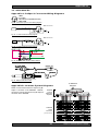
4.2.4.2. Charging Your Batteries
Equipment Connections. Each SW70T or SW70H transmitter comes
equipped with an SWC-POWR Tireless Wireless™ plug-in charger (see
Fig. 4l). In addition, each SW70H comes with its own battery-charging
mic clip (SWC70-CL). The SWC-POWR charger can be plugged directly
into either the transmitter or into the clip. A Sabine rechargeable battery
(SWBC1) will charge whenever the mic clip is connected to the Sabine
SWC-POWR charger and the handheld is properly placed within the
mic clip.
Charging Indicators. Much like your cell phone, the transmitters will let
you know the charging status of the battery. When the battery is charging, the battery meter will flash to indicate the relative level of the charge
— one, two, three or four elements will flash (see Fig. 4i).
Once the battery is fully charged, all four elements in the battery meter
will flash. This indicates that the charging circuit is no longer on (see
Fig. 4j).
NOTE: The right-side indicator segment will flash for several minutes
when charging is first attempted (see Fig. 4h). The lower the battery
level, the longer this initial “testing/not charging” flashing sequence will
continue. During this time, the Tireless Wireless battery circuit is evaluating the suitability and charge status of the battery in place. When it has
completed its evaluation, it will either commence the progressive flashing depicted in figure 4i (CHARGING), or continue to flash (TESTING/
NOT CHARGING). All segments flashing in unison signifies that the
battery is fully charged (see Fig. 4j).
These same indications will also be displayed on the receiver LCD,
and on the Remote Control Software screen.
NOTE: The Tireless Wireless battery charger will only charge NiMH
rechargeable batteries. If you place any other kind of battery in the
transmitter, and then attempt to charge it by connecting the charger, the
Tireless Wireless circuit will detect the type of battery and will not begin
charging. Again, the battery indicator on the transmitter will flash the
right-side element indicating testing/no charging (see Fig. 4h).
Battery Warnings. When the transmitter battery voltage drops below a
critical threshold, the battery icon (which normally displays the voltage
level) will begin to flash. This will occur on the transmitter and receiver
and is an indication that you need to replace the battery, or charge it by
placing the handheld mic in the charger clip. NOTE: Microphone will still
transmit audio when placed in clip. Alternatively, you can connect the
charger directly to the transmitter using the built-in charger jack located
on the side of the beltpack transmitter and near the antenna on the
handheld transmitter (see Fig. 4l). If the battery is not changed or recharged, the transmitter will eventually turn off (see Fig. 4k).
Fig. 4h: TESTING/NOT
CHARGING
Right-side battery indicator
segment will flash to indicate
that the battery is being
tested. This occurs prior to
charging a NiMH battery and whenever a nonrechargeable battery is placed on charge.
Charging is not occuring when indicator lights
in this fashion.
Fig. 4i: CHARGING
Battery indicator segments
will flash progressively starting from the relative charge
state of the battery. This example depicts a fully discharged battery being charged. As the charge
progresses, left-side segments will remain visible as right side segments continue to flash,
until all segments are visible. At that point, all
segments will flash on and off in unison (see
Fig. 4j).
Fig. 4j: FULL CHARGE
Battery indicator segments
will flash in unison to indicate that the battery is fully
charged.
NOTE: Battery can be left
connected to the charger and will receive periodic maintenance charging.
Fig. 4k: Battery CHARGE LEVEL displays
Fully Charged
Partially Used
Very Used
Very Low (Flashing)
SW70T
NOTE: When the battery has reached
a specific discharge level, the transmitter will automatically
turn off, and the transmitter LCD will display
the message at right.
SWC70CL
(Mic Clip for SW70H)
SW70H
Fig. 4l: SWC-POWR plug-in charger for SW70 Series Transmitters & SWC70CL Mic Clip
17
Sabine 2.4 GHz Smart Spectrum® Wireless
E-SWM7000-OpGuide-031219.pmd - hto
Receiver Operation
5. RECEIVER OPERATION
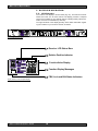
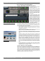
5.1. LCD Display.
The receiver LCD display is shown below (Fig. 5b). Two-channel receivers
feature two LCDs, one for each channel. The display provides a snapshot
report of the condition of your wireless channel, including battery status information sent from the transmitter by telemetry.
The right two-thirds of the display primarily shows status information regarding the condition of your receiver channel, as follows:
Fig. 5a: SW72R front panel
Receiver LCD Status Bars
Relative Position Indicator
Function Value Display
Function Display Messages
FBX, Lock and Edit Status Indicators
Fig. 5b: Receiver LCD Compete Display
Sabine 2.4 GHz Smart Spectrum® Wireless
18
Receiver Operation
Receiver LCD Status Bars
Diversity Status: Either 1 or 2 is lit, showing the active antenna.
RF Signal Strength Indicator: Indicates presence of RF (from transmitter, or
external sources) on the chosen reception channel. The greater the number of
illuminated icons, the stronger the RF signal detected.
Battery Voltage Level Meter: Indicates the battery voltage of the corresponding transmitter; the more segments are illuminated, the higher the voltage, and
the greater the remaining battery life.
Audio Level Meter: Shows the audio input level (received audio signal).
Compression Meter: Shows the active gain reduction applied to the receiver
channel’s audio output.
Function Display Messages
Firmware Version: Displays for 2 seconds on power up; shows the receiver
firmware version.
Transmitter Battery Low: You have 15 minutes or less to change transmitter
batteries.
Mute: Transmitter muted; the transmitter on/off switch is set to mute.
Front Panel Locked: Front Panel is locked and the selected function cannot be
edited. See Appendix D for an explanation of front panel locking.
De-Esser: The De-Esser is actively reducing sibilance.
FBX, Lock and Edit Status Indicators
FBX Status: SETUP is illuminated while the receiver is in SETUP MODE.
READY is the normal operational mode, indicating SETUP has been performed
and FBX filters are active. BYPASS indicates the audio signal is NOT going
through FBX filters (but all other DSP processing is active).
Front Panel Lock Status: LOCK 1 indicates all front panel controls are locked
to prevent intentional tampering, or accidental programming. LOCK 2 indicates
a subset of controls are locked, allowing selected others to be adjusted with
software only. Default LOCK 2 setting locks out all functions except FBX and
Program Load.
Edit Status: In a 2-channel receiver, this field illuminates when the corresponding Channel Button is pushed, indicating Controls are assigned to this
channel.
19
Sabine 2.4 GHz Smart Spectrum® Wireless
E-SWM7000-OpGuide-031219.pmd - hto
Receiver Operation
5.2. Parameter Control & LCD Display
5.2.1. One set of Controls for 1 or 2 Channels
Whether you have a one- or two-channel SWM7000 series receiver is apparent by the number of LCD displays on the front panel. However, only one set
of control knobs is provided for either one- or two-channel receivers. Note
that in a 2-channel receiver, this set of controls is shared, and assigned to a
channel by pushing either the A or B Channel Select button (see Section
5.2.2). Your SWM7000 Series receiver uses Sabine’s Tweek-n-Peek™ digital control system. Whenever you turn a control knob one click, the associated function is shown on two lines of text display in the LCD. The large
numeric display will indicate the current parameter value. Additional turns/
clicks change the parameter setting and display the value as the change is
made. After a few seconds of inactivity, the LCD will revert to its default display
(RF channel).
Fig. 5c Sabine Tweek-n-Peek
Sabine’s Tweek-n-PeekTM
Whenever you turn a control knob one click, the name of the corresponding
function is shown and the current edit setting is displayed on the LCD. This
applies for all the front panel knobs.
For example, if you turn the Compressor ratio knob one click, you will see the
current compression ratio in the Settings Display. The Text display will show
COMP on the first line and RATIO on the second. Subsequent turns will edit
that setting up or down, depending on the direction you turn the knob.
Since the control knobs are continuous rotary encoders with no end points,
the Relative Position Indicator (RPI) is a handy way of seeing where you are
in relation to the full range of the knob in question. In our compressor Ratio
example, if you are at a ratio of 9:1, about the middle of the range, the RPI will
display about one half of the bar. NOTE: The setting range of each control is
printed on the front panel below each knob.
Relative Position Indicator
In our compressor Ratio example, if
you are at a ratio of 9:1, about the
middle of the range, the RPI will
display about one half of the bar.
EDIT will light in the
channel display of the
channel being edited.
Function Display
The Function display will show COMP
on the first line and RATIO on the
second.
Fig. 5d Tweek-n-Peek example
5.2.2. Channel Select / Contrast Button.
The elliptical button immediately adjacent to the LCD has multiple functions.
First, it adjusts the LCD contrast and viewing angle. Change the degree of
angle by pressing and holding the button down. The adjustment range will
cycle in a continuously reversing loop — when it gets to the maximum value
it reverses and begins to decrease in value. You can stop holding the button
down and initiate single button pushes to advance (or decrease) the contrast setting incrementally.
Sabine 2.4 GHz Smart Spectrum® Wireless
20
Receiver Operation
In addition, the Contrast/Channel Select button has another function, in 2channel receivers only (SWM72-R or SWM72-NDR). Such units feature two
LCDs and two Contrast/Channel Select buttons. A single (without continuing
pressure) push assigns all Parameter Control knobs to the selected channel. The button will light, the associated LCD will brighten, and the word EDIT
will appear in the lower left of the LCD, all indicating the active edit channel.
For the active channel, turning any Parameter Control knob will first display
(one click) and then adjust (subsequent turns) the settings of the function
selected, indicating the changes in the Settings Display. For the inactive
channel, turning any Parameter Control knob will display the current setting
in that channel’s Settings Display. The channel must be activated in order
to change settings.
5.2.3. Special LCD Display Messages.
In addition to the Status and programmable information discussed above,
the text lines of the LCD Settings Display may also (under certain circumstances) automatically override other displays. The conditions when this will
occur and the messages displayed are shown on page 19.
Fig. 5e: Contrast button:
Tap to select which channel to control
Hold to adjust contrast and viewing
angle. Range of value is 1 - 30, 15 is
default.
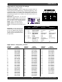
5.3. RF Channel Select
Range = 1 to 70
Choose the RF channel for this system. The transmitter
must have the same channel selected. Turn the RF CHANNEL SELECT knob
until the desired channel is displayed on the LCD. See chart (Appendix E) for
exact frequency of each channel.
NOTE: Dual channel receivers will not allow you to select the same RF channel for both channels.
NOTE: Front panel RF Signal display will only register Sabine transmitters. It
will not show RF interference. Use the RF Scan function in the software to scan
for potential RF interference (see Section 13.4.2.5).
Fig. 5f
5.4. Output Level
Range = MUTE to 0 dB Adjust the output level to match the input characteristics of the downstream component. Each tick of the output level knob adjusts
the level by ½ dB. The LCD displays this in 1 dB resolution, so it takes two ticks
of the knob to change the output level value on the LCD.
The output level varies from microphone level to line level, so if you are patching the receiver to the mic level input of a mixer, turn down the level to avoid
overdriving the mixer input. Minus 15 dB is a good place to start. If you are
patching into a line level device, turn up the receiver output. For best results,
follow the golden rule of gain structure: maximize gain at early stages in the
signal path, to minimize noise that will be accumulated and amplified by adding late-stage gain.
21
Fig. 5g
Sabine 2.4 GHz Smart Spectrum® Wireless
E-SWM7000-OpGuide-031219.pmd - hto
Receiver Operation
5.5. Receiver Antenna Placement
One of the biggest potential problems in any wireless system is RF interference. Understanding wave interference patterns will help you to place and
orient your receivers and antennas properly, and thereby reduce the likelihood
of RF interference.
Your SWM7000 series receiver ships with two standard coaxial bipole antennas. Each antenna picks up in a donut-shaped (toroidal) pattern, more or less
equally in all directions, with null points directly above and below.
5.5.1. Multi-path Interference
Like sound waves, radio waves are subject to wave interference patterns
produced by reflected or delayed waves combining with direct, unreflected
waves, converging upon a receiving antenna simultaneously. In the RF world
this phenomenon is called multi-path interference. As with audio comb
filtering, radio waves can combine additively or subtractively. Thus, mounting
an antenna close to a reflective surface can result in poor reception. For
example, if weaker than expected reception occurs, and the receptive part of
the antenna (the top 3 cm) is close to a reflective surface (wall, large metal
objects, etc.), you might improve reception simply by repositioning, or reaiming, the antennas.
In some situations — for example, those with difficult lines-of-sight, or when
transmitters and receivers are separated by a wall, or when receiver placement options are limited — an extension antenna may be necessary to
guarantee reliable reception. Please refer to Section 12 for information about
the advantages and use of Sabine’s SWASS-EXT Extension Antenna Kit.
5.5.2. Receiver & Antenna Placement Tips
1. When possible, maintain line of sight from transmitter to receiver.
Consider the potential range of transmitter “roaming,” and locate your
receiver accordingly. If direct line of sight proves impossible or difficult,
consider using Sabine’s low-profile, active Extension Antenna Kit
(SWASS-EXT), which boosts the signal strength, extends the maximum
distance from transmitter to receiver, expands and focuses antenna
sensitivity, and allows antenna and receiver to be positioned further
apart or in separate rooms.
Sabine 2.4 GHz Smart Spectrum® Wireless
2.
Decide on front or rear panel antenna mounting (to maintain line-ofsight path). Antennas typically mount on the rear panel of your receiver,
but the included accessory SWA700 front mounting kit can be screwed
onto the front and connected via jumper to the back panel terminals.
When mounting receivers in a rack that is deeper than the receiver,
move the antennas to the front for improved reception. For any rack
mounted receiver, try to keep the top 1.25 “ (3 cm) of both antennas
extended outside the sides of the rack (see Fig. 5h). Non-rack mounted
receivers should be oriented so that the antennas face the transmitters.
3.
Maximize the distance between the receiver and light sources, such
as fluorescent bulbs or neon signs, which may emit very short-range,
broadband interference. These light sources should not be a problem
in normal circumstances, but, as a cautionary preventative, we recommend a minimum distance of 3 meters (10 feet) between them and any
receivers or extension antennas.
4.
Note the placement of any microwave ovens in the immediate vicinity. Place any receivers or extension antennas as far away as is practical from microwave ovens.
5.
Mount receiver antennas at 90 degrees to one another, leaning away
at 45 degree angles, in the same plane. This will decrease the likelihood that one antenna will be susceptible to the same orientationspecific directional or multi-path problems that may affect the other one.
22
Receiver Operation
6.
When using multiple receivers, try to maintain at least 1 foot (30 cm)
distance between antennas from different units. If you are rack-mounting multiple receivers, you may want to avoid spacing them in adjacent
rack spaces, to maintain distance between antennas. When such antenna spacing proves difficult or impossible, we recommend using
Sabine’s Antenna Distribution Amplifier (Sabine SWA6SS), which can
help manage antenna configurations and, more importantly, improve
system-wide interference rejection. The SWA6SS works with up to six
receivers.
7.
In very rare instances, poorly shielded or malfunctioning computers
or digital effects units may cause RF interference. You can test whether
such units are the sources of such interference by switching them off
one at a time, and determining if interference rejection improves.
8.
Turn on your system one component at a time, beginning with the
first receiver. If you don’t have a computer handy, keep all other receivers and transmitters switched off for the time being.
9.
Use the RF Scan function included in the Remote Control Software.
This will give you a picture of the potential interference in your area, both
real-time and over time. Please refer to Section 13.4.2.5. for information
on Sabine Remote Control Software’s Automatic RF Scan function, which
will automatically determine the best RF channels to use.
10. Maintain a minimum distance of at least 3 meters (10 feet) between
transmitters and receivers or extension antennas. This can solve
many anomalies.
11. Be careful not to set more than one transmitter to the same channel;
each paired transmitter and receiver should be set to unique corresponding channels, until all channels are receiving clearly and cleanly.
12. Once the physical placement of your receiver(s) and antenna(s) is
decided, proceed with the remainder of the setup process.
23
Sabine 2.4 GHz Smart Spectrum® Wireless
E-SWM7000-OpGuide-031219.pmd - hto
Mic SuperModeling™
6. MIC SUPERMODELING™
6.1. Introduction
Fig. 6a
Microphones come in a dazzling variety of shapes, sizes, polar patterns, frequency response curves, phase response curves, etc. Few things arouse as
much passion amongst audio engineers as discussions about what microphone to use in a given application. Sound rental companies and recording
studios proudly tout their impressive microphone collections, and singers
frequently favor a certain brand and model number as “perfect for my voice.”
The only viable “please everyone” strategy is to stock a wide assortment of
microphones. This is far easier for wired microphones than for wireless.
Changing a wired microphone is as simple as disconnecting one mic and
connecting an alternative — the same cable and same microphone stand
allows easy interchangeability. At worst you might have to exchange microphone clips along with the microphones themselves.
For wireless microphones, however, the situation is not so simple. With different transmission frequencies, different proprietary designs, different types of
connectors (microphone to belt pack transmitter), and the matched-set nature
of transmitters and receivers, changing a microphone/transmitter is far more
complex.
Sabine has a better idea — Sabine’s proprietary Microphone SuperModelingTM.
With digital technology, it’s possible to start with the sonic signature of a high
quality microphone (such as Sabine’s standard condenser and dynamic capsules used in our SWM7000 handheld series systems), and emulate the
characteristics of other popular microphones—all at the twist of a knob. You
won’t have to change microphones, cables, connections, or receivers, interrupt a performance, or even get up from your mixing chair! Best of all, you will
have an instant answer to a variety of demands from singers and speakers for
their favorite microphone — even if they pass the microphone around.
6.2. Emulation Choices
Sabine Mic SuperModelingTM
SuperModelingTM Dynamic Models*:
- Shure SM-58
Each Sabine SWM7000 receiver (SW72-NDR, SW71-NDR,SW72-R, SW71-R)
comes equipped with 7 different SuperModel microphones available per channel. Four of these (Shure SM-58, Shure Beta 58, Audio Technica ATM 41A, and
AKG D-3800)* are designed for use with either of Sabine’s dynamic handheld
microphone/transmitters (SW70-HD3 or SW70-HD5). The remaining three
(Shure Beta 87A, AKG C535EB, and Audio Technica ATM 89R)* are designed
for use with Sabine’s condenser handheld microphone/transmitter (SW70HC). In addition to these SuperModeling choices, you may prefer to use Sabine’s
high quality microphones “just the way they are;” i.e., without emulation.
Telemetry information sent by the handheld transmitter to the corresponding
receiver (or receiver channel for a 2-channel unit) identifies the type of transmitter, and loads the appropriate emulation library. Note that beltpack transmitters also send telemetry that turns off the Super Model option, as this feature is designed to work only with handheld microphone/transmitters.
- Shure Beta-58A
- AKG D-3800
6.3. Mic Modeling Front Panel Control
Simply turn the parameter control labeled “Mic SuperModeling ” to scroll through
and select the microphone you wish to emulate. The first click of the knob will
show the current setting, without changing it; additional turns will change the
emulation that is active. The top text line of the Settings Display will read either
MICDYN (dynamic) or MICCON (condenser) depending on the telemetry information sent by the handheld; the bottom line will display the microphone being
emulated. Note that one choice is to bypass modeling, and simply utilize the
excellent quality of the Sabine microphone capsules. In this case the bottom
text line will simply read OFF. Finally, whenever telemetry information indicates
that a belt pack transmitter is the RF source, or if a handheld transmitter is
replaced by a belt pack with the same receiver (or some such other unpredictable event transpires), the Settings Display will read MICMOD/OFF whenever
the Mic Modeling knob is turned.
TM
- Audio-Technica ATM 41a
SuperModelingTM Condenser
Models*:
- Shure Beta 87A
- AKG C535 EB
- Audio-Technica ATM 89R
*Company names, product names, and
trademarks listed as modeled are the property of their respective owners and are used
only to identify evaluated microphones used
to develop digital processing; they in no way
imply association, endorsement, or approval
by any named manufacturer.
Sabine 2.4 GHz Smart Spectrum® Wireless
24
Mic SuperModeling™
There are no modeling settings for lavalier or headset microphones — mic
placement makes these an unrealistic choice for modeling. NOTE: other
lavalier microphones can be used with the Sabine Beltpack Transmitter.
NOTE
A very short crossfade of the audio signal occurs when switching between mic
models. This ensures no digital artifacts
will occur when you change the sound
of the mic.
6.4. Future Microphone Modeling Choices
When Sabine adds to the library of “virtual microphones” that are modeled by
the receiver DSP, these will be made available as a firmware upgrade from the
Sabine web site, www.Sabine.com.
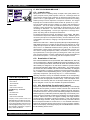
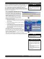
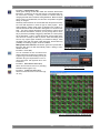
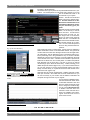
6.4.1. Mic Model Upgrade Instructions
New Mic SuperModeling “virtual microphones” can
be downloaded easily using the remote control software on your PC. NOTE: The Mic SuperModeling Update Wizard can be accessed only from the initial
software startup menu (prior to connecting to a receiver or entering Demo/Edit Mode). If you have already connected and attempt to access the Upgrade
Wizard, the message box at right will appear (Fig. 6b):
To download new mic models:
1. With your PC connected to the Internet, pull down the Sabine
Online menu in the software menu bar and select “Add
New Mic Models.”
TM
2.
Click the “Download Mic Models from Sabine” and follow
the dialog box instructions.
3.
The last dialog box will allow you to either connect to a
receiver and update the mic models on that receiver, or
cancel and complete the upgrade process at a later date.
Note that this dialog box will show the actual file path of the
new mic model file.
Fig. 6b
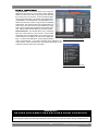
Upgrading from a disk or previously downloaded files:
Mic SuperModeling™ files already downloaded can be flashed
into your receiver using the second option “Load Mic Models
from disk.” Clicking this button opens a dialog box (default diFig 6c
rectory is your “Sabine” directory).
NOTE: File name will always be “micmodels.smm” and will
include all mic models available up to the date the file was downloaded.
NOTE
Mic SuperModelingTM is not available using beltpack transmitters.
CHANGING AUDIX CAPSULES
Sabine's Mic SuperModeling™ function
requires a baseline characteristic for the
capsule in use. Therefore, after changing capsules, you will need to “tell” the
transmitter which capsule is now attached.
NOTE: this is only necessary when the
capsule is changed.
See Appendix G for instructions on how
to reset your transmitter after changing
Audix capsules
25
Sabine 2.4 GHz Smart Spectrum® Wireless
E-SWM7000-OpGuide-031219.pmd - hto
FBX Feedback Exterminator
7. FBX FEEDBACK EXTERMINATOR®
7.1. FBX Introduction
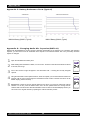
There are two types of FBX filters, fixed and dynamic. Both operate automatically. There is no audible difference between fixed and dynamic filters in
terms of sonic purity; the difference arises in their application.
7.1.1. FBX Fixed Filters
Fixed filters are set automatically during the FBX SETUP and will not change
frequency until manually reset.
Fig. 7a
SETUP Indicator
Fig. 7b: READY Indicator
NOTE: make sure READY is displayed before
using your system for a performance.
FBX SETUP NOTE
LCD “READY” Flashing
As you get close to the end of the setup
procedure, READY will begin to flash on
the LCD. Stop raising the gain! The
FBX will now go into Ready Mode.
7.1.2. FBX Dynamic Filters
Dynamic FBX filters also set automatically, but can change frequency, on a
rotating basis, as the need arises.
7.1.3. Balancing Fixed & Dynamic Filters
Each channel of your SWM7000 wireless receiver offers a total of 10 FBX
filters (combined fixed and dynamic), which can be used as needed to
exterminate feedback. The default setting of 7 Fixed and 3 Dynamic can be
changed to 8 Fixed and 2 Dynamic using the DIP switches on the back of
your receiver (see Appendix D FBX Configuration DIP Switch), or to any
configuration using the Remote Control software (see Section 13).
If you follow setup instructions for setting FBX filters, your receiver will
automatically exit SETUP mode (enter READY status) after all Fixed filters,
and the first Dynamic filter, have set. In the default condition, this means
you will have set eight filters (seven Fixed and one Dynamic), with two
Dynamic filters still unset and remaining on standby alert. If you wish to
set fewer filters, press the READY button before SETUP automatically
exits, after you have set enough filters to safely achieve your desired gain
level. In that case, in the factory default condition, you will reserve three
unset Dynamic filters for standby.
7.1.4. FBX Filter Width
Sabine’s experience and testing with filters and sound quality along led us to
decide upon a default FBX filter width of .10 (one-tenth) octave as the optimal
notch width, able to eliminate feedback without affecting music programs. If,
with all filters properly set, feedback is still a problem, FBX filters may be set
to .20 (one-fifth) octave width. This wider filter setting will help to better eliminate feedback trouble areas, but may also affect music programs slightly.
Therefore, the wider setting is generally considered to be appropriate where
speech (less demanding than music) is the primary application of the Sabine
Wireless system. You can globally change FBX filter width by repositioning a
rear panel DIP switch, to change from .10 to .20 octave (see Appendix D FBX
Configuration DIP Switch), or by adjusting filter width using the True Mobility®
Remote Software (which allows a range of widths from .01 to 1.0 octave).
You may also mix filter widths, either by adjusting individual filter widths
using the Remote Software, or by changing the DIP switch position during
setup. The width of any set filter will always be determined by the position of
the switch at the time the filter is created.
7.2. FBX Set Up
Follow these easy steps to obtain the maximum gain and protection from
feedback. Sabine FBX employs a very fast and quiet setup mode to make it
easy to use.
1. Place the speakers in the positions where they will be used during the
program.
2. If there is any equipment with a noise gate in the signal path, you MUST
DISENGAGE the noise gate(s) prior to the setup procedure. You may
reengage these noise gates upon conclusion of your FBX setup.
3. Patch your Sabine receiver into the mixer or amp channel. Set the amp
master output gain to a normal operating position.
NOTE: The level of your power amplifier should be set to a level that allows
a healthy gain structure prior to the amplifier. If your amplifier is turned up
Sabine 2.4 GHz Smart Spectrum® Wireless
26
FBX Feedback Exterminator
fully, and your mixer meters show little movement when signal passes through,
then your amplifier will have to work harder to process the weak signal. You
will improve the performance of your sound system and lower system noise
by reducing the gain on your power amp and increasing your mixer gain. FBX
response time will also be better with proper gain structure.
4. First, turn on your receiver and select a clear channel (no RF Signal bars
showing). Then turn on your wireless transmitter or handheld microphone
and select the same channel, Now turn on the mixer (gain low), then any
other accessories, and finally the power amp. If you are using a graphic EQ,
adjust only for the desired tonal qualities, but do not notch for feedback!
5. With the microphone turned on, raise the Output Level of the receiver slowly
until a strong input signal at the mixer is apparent. The microphone should
now be audible.
6. Now you are ready to set FBX filters. Press and hold SETUP (far left button)
on the wireless receiver, until the word SETUP in the channel LCD flashes
4 times, then stops flashing. This will clear any FBX filters already in place.
NOTE: You should do this each time you move your sound system, change
a sound system component, or relocate your microphone. Your Sabine
True Mobility Wireless System will remember its settings from the last time
you turned the unit off.
Fig. 7c: READY Button
Tech Tip
READY & Locked Fixed
READY = Lock Fixed on other Sabine FBX
products
7. During Setup mode, do not talk into the microphone or pass audio program through a transmitter. This may cause the Sabine True Mobility™
system to set inappropriate filters. The only appropriate use of the setup
mode is to create and filter feedback. SETUP must be exited prior to normal
microphone usage. This happens automatically after setting FBX filters, or
you may exit manually by pressing READY at any time.
8. Identify the primary usage positions, and likely feedback-prone locations,
in the potential movement range of the wireless microphone. Take the
microphone to the first of these locations.
Fig. 7d:BYPASS Button
9. Slowly raise the mixer channel gain to the point of feedback — and then slowly beyond, until you hear the chirping tones of
feedback quickly being eliminated by FBX filters setting. Stop raising gain after 2 or 3 feedback tones have chirped and
corresponding FBX filters have set. Rest assured that any feedback that occurs will be at a quiet volume, and very short in
duration.
10. Move the microphone to another area of use and slowly raise gain until FBX eliminates a few more feedback tones (2 or
3). Repeat this step until the word Setup automatically disappears and the word READY appears. This indicates your
unit is ready for operation. The total number of filters available for feedback filtering is 10; in the factory default setting,
your unit will automatically enter READY mode when the eighth filter is set. Alternatively, you may enter READY status with
fewer fixed FBX filters in place, simply by pressing the READY button at any time. NOTE: Be sure that the word READY
appears in the FBX section of your receiver LCD during performance or any normal operation.
Any feedback that occurs after setup will be eliminated by dynamic filters, which remain in reserve to catch surprise
feedback if it occurs during performance/operation.
In most instances you will experience an additional gain of 6-9 dB before feedback when using the Sabine True
MobilityTM System. Precise results will depend on system and acoustical considerations.
All fixed filters in place will remain set until the Setup button is pushed and held as described in step 6. All dynamic filters
will remain in place until new feedback occurs (when they will move to the new frequency), or until the Setup button is
pushed and held. Your True Mobility receiver will remember its FBX (and all other) settings even if the power is turned off.
See Section 14 for a complete discussion of Sabine FBX Feedback Exterminators®.
7.2. FBX Bypass Button
The Bypass button bypasses only the FBX Section, and not the additional signal processing (Parametric Filters, Hi/Lo Cut,
De-essing and Compression) available in the Targeted Input Processing section of the Sabine True Mobility™ Wireless
Receiver.
NOTE: You can easily bypass Compression signal processing by turning the Compressor Ratio knob counterclockwise
until you get to 1:1 ratio, and the De-esser signal processing by turning the De-esser knob clockwise until you get to 0 cut.
27
Sabine 2.4 GHz Smart Spectrum® Wireless
E-SWM7000-OpGuide-031219.pmd - hto
Compressor Limiter
8. COMPRESSOR/LIMITER OPERATION
8.1. Basics of Compression
The dynamic range (how loud we can hear to how quiet a sound we can detect)
of the human ear is far greater than the capability of sound systems to reproduce. Although some of this equipment limitation is at the upper extreme of the
dynamic range (where too loud a signal will produce distortion), much of the
restriction occurs at the low level end, where the signal disappears below the
“noise floor” of the circuitry.
A compressor (or in its most powerful form, a limiter) is the most widely used
tool for controlling dynamic range. In the simplest terms, a compressor is
designed to squeeze the dynamic range of an audio program; i.e., to make
quiet signals louder, and loud signals quieter. A compressor becomes a
limiter when the compression ratio (the ratio of the input gain change to the
output gain change) is so high that the output level effectively won’t rise above
a “brick wall” ceiling, regardless of how much the input gain increases (typically a ratio of 10:1 and greater).
A compressor acts like an “automatic mix engineer” with a hand on the fader
and an inhumanly fast reaction time. When the input level increases, the
“engineer” drops the fader; when the level decreases, the fader is raised.
When the amount of fader compensation equals the variation in signal level,
the output level of the audio program will sound consistent.
The practical benefits of compression and limiting include:
1. Speaker protection. A compressor will control sudden level peaks and
prevent your speakers from damage. Most often in this type of application,
the compression ratio is high enough to qualify as a limiter.
2. Perceived increase in loudness. Because compressed peak levels are
kept from rising as high as uncompressed signals, you gain headroom for
your audio program and can raise its overall average gain. Compression
is often added to the entire audio mix, both in live sound and recording, to
increase its perceived loudness.
3. Achieving more consistent levels. For expressive instruments or vocals,
which may have a large dynamic range, compression can help maintain
more consistent mix levels. So a speaker who varies from a whisper to a
shout will not disappear or stand out in the mix, relative to other less dynamic instruments or vocals. Vocal level variations are also common
when multiple users share a single microphone, due to differences in
voice volumes and mic-to-mouth positions from one user to another. Compression will help even out such variations as well.
8.2. Using the Compressor
Compressor knobs are located immediately to the right of the FBX and DeEsser controls. The controls consist of standard Ratio, Thresh (threshold) and
Attack knobs, and a horizontal gain ladder in the LED display shows compressor gain reduction.
Ratio: Compression ratio is the ratio of the input gain change to the output
gain change. The compression ratio on your Sabine Wireless ranges
from 1:1 to 19:1, in increments of 1 dB. Set Ratio to 1:1 to bypass
Compressor.
Thresh: Compression threshold sets the input level at which the compressor/
limiter begins to act on the signal. The input level threshold at which
compression is engaged can be adjusted from -30 dBv to 0 dBv, in
increments of 1 dBv.
Attack: Compressor attack time sets the speed with which signal compression begins once an input signal exceeds the threshold level. The
range may be adjusted from 1 to 99 mS, in 1 mS increments.
Sabine 2.4 GHz Smart Spectrum® Wireless
28
Compressor Limiter
Gain:
(Output Level) Since the output gain is attenuated whenever the input
gain exceeds the compression threshold, the overall output level of a
compressed signal will be reduced. Commonly, this reduced output
gain is compensated for by raising the level of the output signal (the
term is “gain make-up”). Output Level range may be adjusted from
mute (minus infinity) up to +20 dB, in increments of 1 dB (depending
on input).
8.3. Suggested Compression Settings
8.3.1. Vocal Settings
The renowned expressiveness of the human voice is due in large part to its
dynamics. A vocal that varies from a whisper to a scream has a strong
emotional impact, but those same dynamics present a challenge to the
sound engineer. Ideal vocal compression maintains some dynamic range
while keeping the vocal the focal point of the mix.
Ratio:
A soft voice might require a ratio of 2:1, whereas a loud voice
might require a ratio setting of 6:1.
Thresh: The higher the threshold setting, the more signal is required to
initiate compression. Ideally this should be set to reign in peak
levels, and allow signals of lower gain to pass uncompressed.
Threshold settings will depend on the nature and variety of the
signal source. Strong vocalists will require a different threshold
than quiet speakers or singers.
Attack: Short attack times usually work well for voice. However, too strong
a compression ratio, too low a threshold, and too fast an attack
may attenuate speech consonants, which provide important intelligibility cues to the audience, thus compromising clarity.
8.3.2. Guitar Settings
Ratio:
A high compression ratio (with gain makeup) will add sustain to
held notes and chords.
Thresh: Moving the threshold will change the audible thick/thinness of
the guitar tone, but generally you want to compress all the notes
played.
Attack: Be wary of too quick an attack, which may reduce the percussive
attack of the guitar notes.
In general, be wary of too much gain makeup, and too high a compression
ratio, which may make a noisy guitar amplifier more objectionable. Ratio
settings might range from 6 to 20:1, threshold variable, slower attack, soft
knee, output gain boosted slightly to significantly depending on amount of
compression.
8.3.3. Bass Guitar Settings
Bass players use a variety of techniques, often in the same song, that can
benefit from compression. Compressing bass evens out peaks and keeps
the bass level in the mix.
Ratio:
Set to 4:1
Thresh: Set to compress peaks only
Attack: Quick attack, medium release, hard knee (try various release
settings, depending on the speed of notes played)
Gain:
Output boosted slightly
29
Vocals
RATIO
Soft voice
Loud voice
Soft voice
Loud voice
THRESH
ATTACK
Short attack is better for vocals. Be careful not to
over attenuate speech consonants.
Guitar
RATIO
Less Sustain
More Sustain
THRESH
Thinner sound
Thicker sound
ATTACK
Be wary of too quick an attack, which may reduce the
percussive attack of the guitar notes.
Sabine 2.4 GHz Smart Spectrum® Wireless
E-SWM7000-OpGuide-031219.pmd - hto
Compressor Limiter
8.4. Possible Compression Trouble Areas
Like any signal processing, compression can be misused, and improper
application may cause undesirable side effects in the audio signal. Some of
these problems include:
1. Noise. If the threshold for compression is set too low, and the output gain
is raised substantially to make up for the gain loss of compression, the
resulting output signal can be noisy. This is because the overall signal
must be raised significantly to produce the same audible level, and the
noise floor of your equipment will be amplified unnecessarily. This problem will be exaggerated if the input signal level to the compressor is very
low (which will already degrade the signal-to-noise ratio).
2. Breathing. In situations where the compression ratio is high, the threshold is low, and the release time of the compressor is short, the noise floor
will modulate up and down as the audio signal rises above and falls
below the threshold.
3. Over-compression. Applying too much compression to a mix can sometimes result in such evened-out dynamics that the “life” of the music or
speech has been removed or curtailed. Dynamic variation may be a major
component of a performer’s message and command of the audience;
don’t remove dynamics, just control them. This may be particularly true for
percussive musical instruments such as drums.
8.5. Release & Knee Settings
Two other important compressor variables are release time and knee. Release time adjusts the speed with which compression stops and output gain
returns to unity with input gain, once the input signal falls below the compression threshold. Knee refers to the degree with which the full ratio of compression is imposed once the input level threshold is approached and exceeded.
A “hard knee” changes from no compression to maximum compression exactly and immediately at the threshold crossing; a “soft knee” gradually imposes the full compression ratio as the input gain approaches and exceeds
the threshold. In Sabine products, the “softness” of a knee can vary from 1-40,
with the higher level representing the “softest” character. In such a setting,
slight compression will begin well below the compression threshold, increase
as the input gain crosses the threshold, and reach full compression well
above the nominal threshold.
Values for release time and knee are set at the factory: default release time is
250 mSec, and the default knee setting is a “soft” setting of 20. These defaults
can be temporarily changed or reprogrammed using the Sabine True MobilityTM
Remote Software (see Section 13 for details).
Sabine 2.4 GHz Smart Spectrum® Wireless
30
De-esser
9. DE-ESSER
9.1. De-mystifying De-essers
Certain consonant sounds produced by the human voice contain more energy
than others, and have the potential to overload a microphone capsule. This
can produce a disproportionately harsh result when amplified through a sound
system, and/or recorded to analog or digital storage media. The most common and obvious of these sounds (in English and many languages) is the
“ssss” sound, associated with pronunciation of both “s” and soft “c” consonants, also the consonants “t,” “f,” “x” and sometimes “d.” The technical term
for this particular vocal sound is “sibilance,” and the devices that control such
sounds are typically called “de-essers” (or sometimes sibilance controllers).
The frequency range of sibilance will vary depending on the singer/speaker,
the consonant involved, the orientation to the microphone, the microphone
itself, and the normal variations in human vocalization. Cardioid- pattern condenser microphones are especially susceptible to sibilance problems, but
the problem can also occur with other types and patterns of microphones. The
range of frequencies affected by sibilance starts above 2 KHz, and generally
tapers off above 10 KHz; in other words, sibilance is primarily a problem associated with higher frequencies (though not the upper octave of human hearing).
Fig. 9a: De-esser
9.2. The Sabine De-esser
The Sabine De-esser is essentially a type of frequency-band compressor,
active in the 2-10 KHz range, and inactive below 2KHz and above 10 KHz.
Sabine’s algorithm works by dynamically comparing band-specific and associated harmonic energy levels to the total signal energy. When spikes are
detected that correspond to sibilance, a shelving filter is imposed on the appropriate frequency bands, and remains in place only for the duration of the
sibilance. High frequency energy levels that remain below the comparison
threshold do not trigger de-essing, and lows and highs outside the sibilance
range are also passed unprocessed and unaffected. This means the Sabine
De-esser is effective but transparent.
9.3. Using the De-esser
Using the Sabine De-esser is simplicity itself. Turning the knob labeled “DEESS CUT” counterclockwise will increase the amount of sibilance reduction,
by increasing the maximum depth of the shelving filter. The maximum allowable cut is 24 dB.
31
Sabine 2.4 GHz Smart Spectrum® Wireless
E-SWM7000-OpGuide-031219.pmd - hto
Program Save & Recall
10. PROGRAM SAVE & RECALL
Most wireless microphone systems provide control of one or two settings (RF
channel and maybe gain). With so little to remember, the ability to save and
recall system settings has not been necessary. With the Sabine SWM7000
series, however, you get a very sophisticated processor with a variety of adjustable parameters. The ability to save and recall your carefully programmed
setups can be a tremendous time-saver. Your SWM7000 allows you to store
and recall up to 10 different presets.
Fig. 10a: Program Front Panel Buttons
10.1. Saving a Preset
Fig. 10b: Program SAVE YES?
To save a program, press the SELECT button. The last preset used (numbered 01 - 10) will be shown in the LCD Display (see Fig. 10b). If you want to
replace an existing program, press SELECT until you reach that program’s
number. Then press the SAVE button. The function display will show “YES?”.
If you are ready to save, immediately press the SAVE button again, and your
settings will be saved to that program number. The message PRESET SAVED
will be shown for four seconds in the text display to confirm this action, as the
LCD Display continues to show the number (01-10) of the preset (see Fig.
10c). After four seconds, the LCD Display will revert to an indication of the RF
channel.
10.2. Loading a Preset
Loading a program is just as easy. Press SELECT until you locate the program number you wish to load. Press LOAD. The function display will show
“LOAD YES?” (see Fig. 10d). Immediately press the LOAD button again and
your new program, including all the parameters, will be loaded for that channel. The message PRESET LOADED will appear in confirmation (see Fig.
10e).
10.3. Naming a Preset
Fig. 10c: Program PRESET SAVED
Presets, channels and receivers can be named using the Sabine True Mobility
Remote Software. Refer to Section 13 for details.
10.4. Power Off Memory
The SWM7000 retains in memory all settings in effect at the time of being
powered off, and returns to those settings when powered on.
Fig. 10d: Program LOAD YES?
Fig. 10e: Program PRESET LOADED
PRESET NOTES
1. Preset 01 is the System Default (SYSDEF on the front panel) and you cannot
save a preset here. Load this setting when you want to return the receiver to the
factory default settings.
2. Preset names will appear on the LCD only after you name the preset using the
remote control software.
Sabine 2.4 GHz Smart Spectrum® Wireless
32
Multiple Systems Operation
11. MULTIPLE SYSTEMS OPERATION
11.1. Overview
In many circumstances a single wireless microphone system is all that will be
in use at any one time. Larger applications (church, concert hall, theater
stage, conference room, etc), however, can often require a large array of wireless microphones, all demanding flawless uninterrupted simultaneous operation.
Multiple system operation presents at least two important operational challenges: interference among transmission channels, and setup complexity.
The Sabine SWM7000 provides powerful solutions to both, particularly the
interference problems associated with two or more RF channels at work at the
same time, at the same location.
11.1.1. Multiple System Interference
Sabine’s SWM7000 addresses multiple system interference with two strategies. First, greater available bandwidth in the 2.4-2.4835 GHz range means
more channels can occupy the band, i.e., the expanded range can be divided
into a greater number of separate transmission/reception bands. Second,
with Smart Spectrum transmission and reception, channels are more tolerant of interference. The net result is that the SWM7000 offers the potential for
many more simultaneous transmission channels than conventional UHF or
VHF systems.
While such performance benefits are one of the major advantages of the
SWM7000, more systems working at the same time leads to a greater potential for complexity. Fortunately, the SWM7000 also offers tools to simplify
setup and operation.
11.1.2. Setup Complexity
Multiple wireless systems in a large installation are of course more complicated than a single transmitter/receiver. More space is needed, and the
sheer quantity of transmitters and receivers that may be in use at a single
installation can prove difficult to manage. The SWM7000 series helps manage such potential complexity with four strategies and/or system accessories:
1. First, the SW72 and SW72-NDR receivers offer a 50% space-saving
advantage with 2-channel receivers that occupy the same 1U space as
single channel receivers. Each channel in a 2-channel system shares
the true diversity operation of the two antennas connected to the single
receiver chassis.
2.
Second, the optional SWA6SS (six-system antenna distribution amplifier) greatly reduces the complexities of multiple receiver antenna deployment. Since each receiver has two (diversity) antennas, which can
be mounted on either the rear or front panel, multiple receivers at one
location can potentially create a forest of antennas protruding from the
front or back of a rack. The SWA6SS Antenna Distributor reduces the
number of antennas to as few as 1/6 what would otherwise be needed.
An added important advantage of using the SWA6SS is its distributed
signal boost provided to all the antenna outputs, delivered while maintaining diversity in all attached reception channels.
3.
Third, large installations often entail long distances from transmitters
to receivers, or the presence of obstacles (walls, for example) in the
transmission path that can interfere with clear reception. While the
SWM7000 series is designed to minimize these kinds of problems
without accessories, the SWASS-EXT (set of two extension antennas,
shown in figure 12b on page 36) may prove helpful or even necessary
in some situations. In addition to providing remote and/or desirable
low profile positioning with improved reception, the SWASS-EXT also
adds another 18 dB of antenna gain for even more reliable system
performance. The Extension Antenna and Distribution Amplifier components are also designed to operate in tandem, with the Extension
Antenna plugged directly into the amp, which can then feed (via cable)
33
Sabine 2.4 GHz Smart Spectrum® Wireless
E-SWM7000-OpGuide-031219.pmd - hto
Multiple Systems Operation
the antenna inputs of 6 receivers. A combination of 2-channel receivers
(SW72-R or SW72-NDR), a set (2 pieces) of SWASS-EXT, and one
SWA6SS, would reduce the antenna clutter of 12 transmission channels to a single pair of extension antennas. See Section 12 for more
information about setup and use of the SWASS-EXT.
4.
Fourth, software control for the ND series receivers allows up to 70
receiver channels to be controlled from a single computer. This quick
and powerful control methodology means you can monitor and change
transmission channels, mic modeling, compression and de-essing —
in short, all front panel controls — from a remote laptop or desktop. In
addition to simplifying multiple unit operation with remote front panel
controls, the remote software provides additional features and functions not available from front panel control. See Section 13 for more
information about setup and use of the Remote Software.
11.2. Antenna Distribution Amplifier
Sabine’s optional accessory SWA6SS Antenna Distribution Amplifier is ideal
for simplifying antenna set up when multiple receivers are used, by using a
single pair of antennas to replace pairs for up to 6 different receivers. Standard
equipment packed with each Antenna Distributor includes an AC power cable,
and 6 pairs of 1-meter long jumper cables (RG-58 AU foam core) for connecting the Antenna Distributor to receivers (2 cables provide true diversity reception to each receiver).
For best results, the Antenna Distribution Amplifier should be positioned close
enough to the receivers to minimize cable runs. In most applications, you can
use the standard Sabine 2.4 GHz antennas supplied with any of the receivers
to connect to the terminals on the Antenna Distributor, and then connect (in
matching pairs) the jumpers to all your receiver antenna connections (up to 6
receivers, 1 pair per receiver).
Care should be exercised when using longer cables, due to possible transmission signal loss (approximately 1.7 dB/meter). Using the “rule-of-thumb”
that a signal loss no greater than 6 dB will prove acceptable in many circumstances, you may be able to use RG-58 cable up to 3 meters or so in length.
However, a better strategy than moving the Antenna Distributor to a better
position, and risking excessive transmission loss back to the receivers or
requiring an upgrade to more expensive cable, is to utilize a pair of Sabine
Extension Antennas (SWASS-EXT). These will connect to the antenna inputs
of the Antenna Distribution Amplifier, and offer increased range, better rearsource RF rejection, an expanded 180 degree forward sensitivity, flexible mounting options, and signal boost (see Section 12).
For more details regarding specifications and operation of the SWA6SS Antenna Distribution Amplifier, please refer to the operating guide included with
that product.
Sabine 2.4 GHz Smart Spectrum® Wireless
34
Multiple Systems Operation
11.3. Antenna Distribution Amplifier Connection
1
To Extension
Antennas
Connect receiver Antenna 1 input to any RF
Output 1 connector on the SWA6SS.
.
SWA6SS
Antenna
Distribution
Amplifiers
Receiver
RF Output 2
Antenna 2
2
Antenna 1
Connect any receiver Antenna 2 to any RF
Output 2 connector on the SWA6SS.
Receiver
3
RF Output 1
Antenna Distribution
Amplifier (SWA6SS)
Antenna Distribution
Amplifier (SWA6SS)
SWM7000
Series
Receivers
Continue with remaining receivers
Fig. 12a: SWA6SS Antenna Distribution Amp Back Panel
! IMPORTANT !
Active Electronics Antenna
Sabine wireless receivers provide
antennas with active electronics. The
inputs to the receiver & antenna distributor amplifier have phantom ower
available for this purpose.
DO NOT SHORT TO GROUND
! IMPORTANT !
Antenna Cabling Impedence
must be 50 Ohm.
35
Sabine 2.4 GHz Smart Spectrum® Wireless
E-SWM7000-OpGuide-031219.pmd - hto
Extension Antennas
12. EXTENSION ANTENNAS
12.1. Overview
Sabine’s SWM7000 series receivers are designed for easy interface with
Sabine’s SWA-SSEXT Extension Antenna Kit (figure 12b). This triangular, attractive wood-grained unit is designed to mount easily and unobtrusively on a
wall (allowing either a through-the-wall or out-the-bottom connection), or (by
threading) atop a microphone stand for a more portable or temporary positioning. Each package contains 2 Extension Antennas, all necessary mounting
hardware (screws and mic stand thread connectors) and both right-angle and
straight connectors for mating with RG-58 cable (for connections to a receiver
or Antenna Distribution Amplifier).
12.2. Antenna Cabling & Cable Loss
Fig. 12b SWASS-EXT Mic-stand mount and
wall-mount extension antennas
While an extension antenna affords the opportunity to increase the distance
from transmitter to receiver, there is a loss of signal in the interconnecting
cable that limits that distance. The maximum connection length is determined
by the type of cable used, and the degree of signal attenuation acceptable.
Let’s presume that an acceptable degree of loss over the total cable run is 6
dB. Without external signal boosts, the different cables shown in the table
would then allow maximum lengths ranging from less than 4 M (RG-58) to 24
M (RG8/U). Thus, for a passive extension antenna, your choices are to limit the
cable run, or increase your budget and buy the more expensive, thicker cable.
Coaxial Cable Attenuation Table - 2.4 GHz
Cable
Type
10 Meter
Attenuation
(dB)
Maximum
Practical
Distance Using
SWASS-EXT
(meters)
Connector
Type
Belden #
Insulation
Center
Conductor
RG58
9203
Polyethylene
#20 Stranded
-16.29
14
TNC
RG58/AU
9311
Foam Polyethylene
#20 Stranded
-11.10
20
TNC
RG212/U
9861
Polyethylene
#15.5 solid,
Silver Plated
-6.11
36
N
RG8/U
9913
Semi-solid Polyethylene
#10 Solid
-2.50
88
N
RG142
83242
Teflon
#18 Solid,
Silver Plated
-6.54
34
TNC
Fig. 12c Coaxial Cable Attenuation Table
! IMPORTANT !
Antenna Cabling Impedance
must be 50 Ohm.
Sabine 2.4 GHz Smart Spectrum® Wireless
Fortunately, Sabine’s SWASS-EXT Active Extension Antenna offers a far better,
more cost-effective solution, due to its built-in active 18 dB signal boost. In the
case of low-cost RG-58 cable, adding an SWASS-EXT to your setup increases
the acceptable maximum cable run by more than 4 times, to 14 meters. With
RG-8 cable, the maximum length is extended to 88 meters!
Power for the Extension Antenna is delivered from any Sabine SWM7000 series receiver or SWA6SS Antenna Distribution Amplifier (see Section 11).
An additional advantage of using Sabine’s SWASS-EXT Extension Antenna
stems from its more focused, directional nature. Sabine receiver’s coaxial
dipole antennas (standard equipment that mount directly on the front or rear
panels of the receiver or SWA6SS) are more omni directional in nature. In
contrast, the Sabine’s Extension Antenna is sensitive to RF reception in a 180degree arc in front of its mounted position. It extends sensitivity to the front and
off-axis side locations as it increases rear RF rejection.
The multiple functions (relocation of antenna, boost of signal, directional sensitivity) of Sabine’s Extension Antenna mean there are many applications in
which its addition to your system can greatly enhance performance. Here’s a
short list of such applications:
36
Extension Antennas
1. Antenna repositioning. Provides solutions when receiver placement options are limited or challenging. Sabine’s Extension Antenna’s multiple
mounting options allow higher placement (wall mount or microphone stand
mount).
2. Barriers interrupting transmission. Anytime a barrier interferes with transmission and reception, Sabine’s SWA-SSEXT can be mounted on the transmitter side of the barrier with cable connections made on the receiver side.
Perhaps the most common situation of this nature would arise when receiver and transmitter are located in separate rooms.
! IMPORTANT !
Active Electronics Antenna
Sabine wireless receivers provide
antennas with active electronics. The
inputs to the receiver & antenna distributor amplifier have phantom ower
available for this purpose.
DO NOT SHORT TO GROUND
3. Expanded or directional sensitivity required. Sabine’s Extension Antenna picks up in a 180-degree arc, focused towards the front. Reception
in this arc is enhanced.
4. Rear RF rejection required. Because Sabine’s Extension Antenna is less
sensitive to signals received from the rear, it can be positioned to reject any
such directional RF interference.
5. Extended operational range. Given a potential maximum cable length of
almost 100 meters from Extension Antenna to receiver, Sabine’s SWASSEXT allows more options for extending the distance between transmitter
and receiver. (It should be noted that the typical range of Sabine’s SWM7000
series systems without the Extension Antenna is already 100 meters in
typical circumstances). Consider that RF signal strength through the air is
diminished by the square of the distance (twice as far away = ¼ the signal
strength), while signal loss through cable is (roughly) inversely proportional (twice as far away = ½ the signal). That means you can use an
extension antenna to replace transmission-through-air with transmissionthrough-cable, to help minimize signal loss.
The SWASS-EXT provides the following benefits:
•
Wall mount or mic-stand mount
•
Straight and right angle TNC connectors
•
180 degree reception pattern
•
+18 dB boost in RF
•
Matched pairs
•
Wood-tone finish
•
Phantom-powered from either the receiver or the distribution amp
37
Sabine 2.4 GHz Smart Spectrum® Wireless
E-SWM7000-OpGuide-031219.pmd - hto
Remote Control Operation
13. REMOTE CONTROL OPERATION
13.1. Overview
In many circumstances you will adjust and control your Sabine SWM7000
wireless microphone system using the front panel controls, as outlined in
previous sections of this operating guide. In circumstances where an enhanced level of control over a single receiver is desired, or to enable simultaneous computer-based control of multiple receivers, you will need to install
(on either a laptop or desktop computer) the free Sabine SWM Remote Control
Software included with your system. Only receivers may be remotely controlled; handheld and belt pack transmitters cannot be remotely controlled.
For online instructions for any function in the software, you may also refer to the
Help menu.
NOTE: Some SWM7000 receivers
may not have a USB port. In this
case, simply use a USB to RS-232
9-pin adaptor. Go to Sabine.com for
a list of suggested adapters.
13.1.1. Single vs. Multiple Receiver Control
All SWM7000 series receivers have an RS-232 9-pin serial COMM Port and a
USB port. Thus, any single receiver can be controlled remotely. Control over
multiple receivers from a single computer is possible only with ND-series
receivers (SW71-NDR and SW72-NDR). These units have additional RS-485
network connections (RJ-45 jacks) for daisy-chain connection from one receiver to the next. Up to 35 receivers (70 transmission channels if all receivers
are 2-channel) may be connected in this network, all under the control of a
single computer. Single- and dual-channel receivers can be mixed in the same
network. The first receiver in such a network can be connected to the computer
via an RS-232 9-pin serial cable or USB cable. The remaining units connect
via an RS-485 cable.
NOTE: It is not possible to upgrade/retrofit a standard receiver to make it an
ND-series unit.
13.1.2 Features & Controls Added Software
All front panel controls and displays are duplicated in the software. In addition, a deeper level of software control over receiver operation is enabled.
These new controls are complete and independent for each transmission/
reception channel, meaning there are two sets of controls for dual channel
receivers. These controls and displays include:
•
Parametric filter access and control. FBX filters can be changed to
parametric filters, and their width, depth, and frequency can be adjusted.
Changes can be made at any time, both before and after FBX filters
have been set. Parametric and FBX filters can be mixed in any combination, totaling 10 for each receiver channel.
Sabine 2.4 GHz Smart Spectrum® Wireless
•
Adjustable FBX parameter control. Maximum depth of FBX filters can
be adjusted globally; filter width can be adjusted globally or individually.
Two controls, Sensitivity and Persistence, can be tweaked to tailor the
operation of automatic FBX filter placement to match the audio program. Proper settings will optimize the balance between false filtering
and delayed response to feedback (the factory default settings should
operate excellently in the vast majority of conditions and may never
need to be changed).
•
Control over balance of FBX Fixed and Dynamic filters. Any FBX filter
can be set to be either fixed or dynamic.
•
Adjustable high and low cut filters. (Software only) High Cut Filter, user
controllable between 3 KHz and 20 KHz, 12 dB/octave roll-off; Low Cut
Filter user controllable between 20 Hz and 1 KHz, 12 dB/octave roll-off.
•
Additional compressor controls. Aside from adjustments for ratio,
threshold, and attack (which duplicate front panel controls), the Remote
Software provides control of compressor release time and knee. The
effect of compression on the output signal as a function of input signal
strength and parameter settings is displayed in Sabine’s unique dynamic ColorComp graph, in addition to the traditional opposing-meter
indicators.
38
Remote Control Operation
•
RF Scan and Report, which measures strength for each of the 70 transmission channels, and displays a hierarchical ordering of the clearest,
strongest channels to use during system setup and operation. You can
print a copy of the scan results.
•
Additional memory options. In addition to saving presets in receiver
memory, channel configuration settings can be saved to and recalled
from disc or hard drive. All parameter settings made with the remote
control, including adjustments that are not accessible from front panel
controls (e.g., compressor knee and release), are saved with presets.
All software settings stored for each of the 10 presets, including settings not accessible from the front panel, will be loaded whether presets are recalled by remote control or from the front panel. Note that all
settings made in Off-line/Edit mode can be saved and applied in online
operation.
•
Ability to print a report of all parameter settings, creating hard copy
documentation.
•
A receiver channel output mute button.
•
The ability to custom name each RF channel and receiver. This name
will be displayed in the software only.
•
Display of important transmitter status information. In addition to
duplicating the battery charge status, battery warning message, and
transmitter on/off/mute status from the front panel display, the Remote
Software displays the number of hours the battery has been in use, the
frequency midpoint (in GHz) of the transmission channel chosen, the
transmitter pad and low cut filter settings, and a warning indication in
the case of low RF signal strength. For handheld transmitters, the
software display also shows the type of mic capsule in use.
•
Improved and expanded operational displays. In addition to organizing all front panel displays on a single computer screen, the Remote
Software also displays the exact frequency, width, and depth of FBX
filters. The frequency response curve resulting from combined filter
settings (including FBX, parametric, and high and low cut) is graphically
displayed in the software. Frequency response changes imposed by
choosing various microphone models are also shown.
•
Customizable front panel lock settings. Software control allows you to
program selective access to front panel controls to be made available
once the Remote Control is disconnected. Customizable front panel
lock settings are saved and recalled as part of each receiver’s settings.
All software-only accessible settings are saved with presets. Careful
programming enables some powerful operational features — for example, locking Program Save but enabling other front panel controls
(including Program Load) will let front panel users update settings temporarily, yet reload the original settings at the push of a button. Such a
temporary adjustment would not permanently alter a setup designed to
work in most situations, but would allow tweaking to address unusual
situations.
WARNING:
BEFORE DISCONNECTING RECEIVER FROM COMPUTER
Quit all SWM7000 Software functions and close software BEFORE disconnecting the receiver connection to you computer.
Failure to do this may cause the receiver to lock up. In case of receiver lock up, restart receiver.
39
Sabine 2.4 GHz Smart Spectrum® Wireless
E-SWM7000-OpGuide-031219.pmd - hto
Remote Control Operation
13.1.3. Software Multiple Unit Control
The true extent of the power of the SWM Remote Software is realized when it
is used to control multiple wireless receivers. When ND-series receivers
are connected in a network, the additional controls offered by the Remote
Software over the entire system include:
•
Simultaneous multiple channel/system monitoring. The Remote Software “All Channel View” (figure 13h) shows all important status conditions for up to 70 transmission channels. Color-coded warnings and
alerts draw attention to potential problems.
USB DRIVERS
Your USB enabled SWM7000 receiver
requires version 2.0 or above software.
Installing this software will also install the
necessary USB drivers onto your computer. If at any time you need to re-install
USB drivers, use the software CD supplied with your receiver, or download them
from Sabine.com.
NETWORK
CABLE CONNECTIONS
Connect the first receiver of a network
using a USB or RS-232 9-pin connection.
All subsequent receivers connect to each
other via RS-485 connection.
•
Detailed, quick access to a single set of controls. The “Command
View” (figure 13c) displays comprehensive information about a single
selected RF channel, and easy adjustment of all its controls. Channels
are selected by clicking the appropriate All Channel View button. (NOTE:
Each channel display in the All Channel View also allows quick access
to parameter adjustments, by using the right mouse button to popup a
parameter control menu.)
•
Quick, interactive control of wireless network channels. All or selected parameter settings for a given channel can be copied to one or
more additional channels, using the Copy Parameters option.
13.2. Software Installation
13.2.1. Requirements & Recommendations
•
PC Minimum Requirements: Pentium 266 MHZ CPU or AMD Duron
CPU; 128 Megabytes of RAM; 20 Megabytes free space on hard drive;
Windows 95 or higher.
•
PC Recommended Requirements: Pentium 1.0 GHZ CPU or AMD
Athlon CPU; 512 Megabytes of RAM; 20 Megabytes free space on hard
drive; Windows 2000 or XP.
•
SVGA or greater resolution graphic card and monitor. Recommended
minimum monitor resolution: 1024 x 768 pixels (or 800 x 600 pixels for
15 inch monitors). Select “small fonts” and 16 bit color as defaults for
monitor display. Windows XP users select 96 dpi screen settings.
•
USB or Serial COMM Port.
13.2.2. Connections
There are three types of connections that are used in a remote controlled
one-or two-channel Sabine SWM7000 system:
•
Serial port (RS-232 9-pin): Use this to connect to a single receiver, or
the first receiver in a network (multiple receivers). Be sure to use a cable
with standard 9-pin D-connectors (male on one end, female on the
other) that is a “serial,” not a “null modem” cable.
•
NOTE: Some SWM7000 receivers may not have a USB port. In this
case, simply use a USB to RS-232 9-pin adaptor. Go to Sabine.com for
a list of suggested adapters.
NETWORK
DIP SWITCH SETTINGS
USB: Use this to connect to a single receiver, or the first receiver in a
network (multiple receivers).
•
Network (multiple SWM7000-ND series receivers):
1. Connect the first receiver in your network to the PC using a USB cable
or an RS-232 Serial Cable (not supplied).
UP: All but the first receiver connected to a
network.
DOWN: First receiver
connected to the network.
Sabine 2.4 GHz Smart Spectrum® Wireless
2. Connect all other receivers as a chain using RS-485 (or standard
Ethernet) cables. There are two such jacks on the back of all ND-series
receivers. Either jack can connect to another receiver either “upstream”
or “downstream” from the computer remote control. As signals travel in
both directions (from computer to receiver and back), it is not necessary
to connect the last receiver in a network back to the computer (you do not
need to make a “loop”).
40
Remote Control Operation
3. IMPORTANT: Set dip switch #7 on the back of the first receiver to the
“OFF” (down) position (default). Set dip switch #7 on all other networked
receivers to the “ON” (up) position.
4. When all cable connections have been made, open the SWM7000
Remote Control Software program on your PC. The SWM7000 software
will find all the receivers in the network and show them in a dialog box
(receiver sequence can be reordered). Click “Accept” to control the network. NOTE: Up to 35 2-channel (or 1-channel, or any combination
thereof) receivers – totalling up to 70 transmission channels – can be
connected in a single network to a single PC.
13.2.3. Installing the Software
Follow these simple instructions for installing the Sabine SWM Remote Software on your computer:
1. Insert the Sabine software CD into your PC’s CD ROM drive and wait a
few seconds for the auto-start software installer to open.
2.
Select the SWM7000 Remote Control Software installation icon and
follow the instructions given in the dialog boxes that appear. NOTE: For
best results, allow the installation program to install the software within
the default directories.
13.3. Launching the software
Launching the software produces the Startup Screen (Fig. 13a).
13.3.1. Off-Line Edit/Demo
Clicking the right button (“Off-Line Edit/Demo”) will open the main software
screen regardless of whether any SWM receivers are connected. The software functions in Off-Line mode are completely programmable, and may be
saved and downloaded to a connected receiver at a later time. Display
settings (e.g., level, compression, transmitter settings) which are dependent on the presence of actual signal are simulated, for demonstration only.
You may turn the simulated displays on or off using the OPTIONS menu.
13.3.2. Connecting Receivers.
Clicking “Connect Receiver” will direct the software to poll the bus on the
designated COMM Port to detect connected, powered-on receivers. If no
receivers are detected, you may change the designated COMM Port by clicking the appropriate button. If this also proves ineffective, check your cables
and connections, and make sure the connected receivers are powered on.
In very rare instances you may need to reset your COMM Port settings on your
computer.
Once polling is completed, the software will display all the receivers detected, in sequence, and the model of each receiver (ND series or standard,
1 or 2-channel). (See figure 13b for a sample opening display)
Once you confirm that the information reported is correct, proceed to the
main screen, and you may begin remote control operation.
41
Fig. 13a Control Software Startup window
Fig. 13b - Connection Screen
Sabine 2.4 GHz Smart Spectrum® Wireless
E-SWM7000-OpGuide-031219.pmd - hto
Remote Control Operation
13.4. Remote Control Operation
Fig. 13c - Control Software Command View
13.4.1. Two Views, Two Sets of Controls
The default main screen appears
as shown in figure 13c.
The top portion of the screen
(above the “Active Channels” bar
and two arrow buttons) is the
Command View, showing details
and allowing parameter adjustments for a single receiver channel at a time.
The bottom portion (below “Active
Channels”) is the All Channel View,
capable of simultaneously showing the most important (but less
detailed) information for multiple
channels. Each audio (RF) channel in the system has its own display box, arranged in rows of eight
channels each, organized in order
to correspond to the string of receivers in the serial bus.
If you have 8 or fewer RF channels, both View Modes will fit on your monitor.
For more than 8 channels, there are quick shortcuts for optimizing your display and switching and mixing View Modes:
•
Click and drag the Active Channel bar to pull the All Channel View up or
down, partially or completely covering the Command View. You cursor
will change to a hand icon.
•
Use the up/down arrows flanking “Active Channel” to scroll the rows
displayed in the space allocated to the All Channel View.
•
Click on the Command View or All Channel View button in the upper left
menu bar (or use F2 and F3), to immediately change from one to the
other.
•
To select a channel to edit in either view, left click on a channel in All
Channel View (indicated by a red border around the selected channel).
This displays the selected channel’s settings in the Command View. A
right mouse click on a single channel shown in the All Channel View
pops up a menu of parameters (see figure 13d). The value of the
parameter selected is displayed in the All Channel View for each RF
channel, and also pops up an adjustment screen for the selected channel. You can review and compare settings on all channels, one parameter at a time, and adjust any setting on any unit from the All Channel
View.
•
Parameter adjustments in the Command View can be made by clicking
and turning any knob; or by a right-clicking on a parameter to pop up an
adjustment window, and keying in a value.
Fig. 13d - All Channel View (after right-clicking
and selecting Ratio).
13.4.2. Menus, Icons & Hot Keys
Quick access to the features described above, plus some additional software control, is available from four pull-down menus (File, Select Receiver,
Options, and RF Scan) and five icons (FBX, Lock, Command View, All Channel View, and RF Scan) at the top of the screen. The controls associated with
the five icons can also be accessed using function keys F2 through F6,
respectively. Figure 13e shows the location of the menus and icons, and
describes associated controls which are accessed.
Sabine 2.4 GHz Smart Spectrum® Wireless
42
Remote Control Operation
13.4.2.1. FBX Settings (F4)
Allows global settings of FBX filter width and maximum allowed FBX
filter depth. As filters are set, they will conform to the global width chosen at the time of setting. It is thus possible to mix filter widths by
changing the width value in between setting FBX filters. Maximum depth
will be common to all FBX filters, and the value will update if the global
setting is changed.
Sensitivity and Persistence are controls that allow the speed and analysis of the FBX algorithm to match the type of audio program. Some
audio programs, notably certain types of classical music, produce occasional waveforms that are difficult to distinguish from acoustic feedback. The factory default Sensitivity and Persistence values should
work in almost all conditions; however, you may change them if necessary to prevent the possibility of triggering a false filter, or to more quickly
set the FBX filters. There is a trade-off between speed of filter placement and how carefully the filter is placed. More demanding audio
sources may require higher Sensitivity & Persistence settings, which
will slightly slow down the speed of filter placement, but decrease any
possibility of mistaking program audio for feedback.
FBX Dynamic Filter Time Out This function gives each dynamic filter a
time limit, after which the filter automatically resets. A setting of “zero”
disables the timer.
Fig. 13f - FBX Parameters window
13.4.2.2. Lock (F5)
You can customize the mix of functions that
will be locked when choosing Front Panel Lock
2 (figure 13g). Front Panel Locking can only be
activated using the Dip Switches on the receiver back panel. See Appendix D for more
information.
13.4.2.3. All Channel View (F3)
Shows the All Channel View as a (vertically)
resizable window (figure 13h).
Fig. 13g - Front Panel Lock Setup
13.4.2.4. Command View (F2)
Shows the Command View on the screen (figure 13c).
Fig. 13h - Active Channels Window - All Channel View
43
Sabine 2.4 GHz Smart Spectrum® Wireless
E-SWM7000-OpGuide-031219.pmd - hto
Remote Control Operation
13.4.2.5. RF Scan (F6)
Use the RF scan to get a “picture” of the potential RF interference in your
location. You should perform a scan before every program so you can
see the ambient RF levels on all
70 channels of your system.
Caution: The RF Scan mutes and
Selectable
takes control of the selected chanThreshold
nel. All other functions are disNow scanning
this frequency
abled on the selected channel. Do
not perform an RF scan on a channel you need during your proSabine
RF Interference
Transmitter
gram!
Select RF Scan by using the toolbar
button, the F6 hot key, or the RF
Scan menu item. You will see the
screen shown in Figure 13i. Select Single Scan or Continuous
Scan if you want to look at the RF
levels over time. The software will
take control of the selected receiver,
Fig. 13i RF Scanner results: one Sabine Transmitter (will display as a green line) and some
and will step through all 70 chanlow-level RF interference (will display as red lines)
nels. You can control the speed of
the scan using the Dwell Time adjustment.
Fig. 13j RF Scan data history
Scan results are shown in several ways. A thick green line indicates a
Sabine transmitter is active on the associated channel. Thin green lines
on either side of that line show RF signal levels for left and right antennas respectively. This RF Diversity function is especially useful for antenna positioning when using distribution amp. A red line indicates
ambient RF is present on the channel, at a level indicated by the scale
on the left side of the chart. A dotted red line indicates a previous RF
level from an earlier scan, and a small yellow “T” indicates the peak RF
level observed over the entire time. Left click on any line or channel
number brings up the “RF Scan data history” window, allowing you to
disable the specific channel (figure 13J). If you chose Continuous Scan
you can also choose to see the Channel Details (figure 13k) and a
history of all RF activity on a particular channel for the duration of the
Continuous Scan (figure 13k).
Channels with very low RF signals (below -70 dBm) should be considClick the channel number to open the Scan Data
ered open channels. We include this low level measurement so you
History window. Click the Toggle Channel Skipping
can see the activity in your location, but the Sabine transmitters will
button to turn the channel on/off. Channels
“skipped” will have a red “X” beneath their channel
overpower and ignore those very low signals.
number.
You can choose to disable all channels with ambient RF levels above
a selectable threshold. Click and
drag the dotted horizontal purple
line to change the threshold (figure 13i). Choose Block Channels
to disable channels above the
threshold. These channels will no
longer be available when selecting RF channels from the front
panel of the receiver.
Fig. 13k RF Signal Strength History
RF SCAN CAUTION
Do not perform an RF scan during your program!
Sabine 2.4 GHz Smart Spectrum® Wireless
44
Remote Control Operation
13.4.2.6.
Options Menu
Copy Parameters. This window allows you to copy your
settings for all functions to any number of other channels.
Select the channel you want to copy from by first selecting
the receiver, then the channel. From the Options Menu,
choose Copy Parameters. You will see your selected channel displayed in a red field labeled “Copy Parameters From.”
Select the channels you want to copy to from the Available
Channels list, then check the boxes of the parameters you
wish to copy. Once you are sure of your selections, hit Copy
Now and your settings will be pasted to the selected channels. Note that RF channel selections cannot be copied.
Reset Parameters. This window allows you to selectively
reset any of the functions in your receiver. Choose Reset
Parameters from the Options Menu, then check the boxes
of the functions you would like to reset to their default settings. In order to reset FBX filters, use the dedicated button
on the Command View. If you wish to load the factory default for the
entire receiver, choose Preset 00 from the Program drop-down on the
Command View and select the Load button.
Fig. 13L Copy Parameters window
Fig. 13m Reset Parameters window
WARNING:
BEFORE DISCONNECTING RECEIVER FROM COMPUTER
Quit all SWM7000 Software functions and close software BEFORE disconnecting the receiver connection to
you computer. Failure to do this may cause the receiver to lock up. In case of receiver lock up, restart receiver.
45
Sabine 2.4 GHz Smart Spectrum® Wireless
E-SWM7000-OpGuide-031219.pmd - hto
Tips & Troubleshooting
14. TIPS & TROUBLESHOOTING
14.1. Tips for Maximum Performance
•
Keep a clear and unobstructed path between transmitter and receiver.
•
Position receiver antennas at least one meter off the performance floor
level.
•
Avoid placing receiver antennas near large metallic or other dense
materials.
•
Keep receiver antennas away from RF signal generating equipment
(computers, high-voltage equipment, etc.).
•
Position antennas perpendicular to each other.
•
Use a Sabine Antenna Distribution System (SWA6SS) for multiple system installation.
•
Return transmitters to a charger when not in use.
•
Use a Sabine SWASS-EXT Extension Antenna to extend range and/or
improve reception.
14.2. Troubleshooting
Problem: True Mobility receiver and transmitter power are on, receiver RF
Signal meters and Input Level meters are lighting up, but there is
no sound from system.
Solution: Check connection between receiver and mixer/amp. Adjust receiver Output Level control. Check for MUTE status in Remote
Control Software. Make sure RF scanner is OFF.
Problem: True Mobility receiver and transmitter power are on, but receiver
RF Signal meters and Input Level meters are not lighting up.
Solution: Check transmitter On/Battery Indicator. Recharge transmitter if
necessary. Check transmitter and receiver frequency Channel
settings (make sure they match). Check receiver antenna connections. Check distance between transmitter and receiver antennas and possible obstructions in path.
Problem: Transmitter is on, but sound is noisy.
Solution: Check transmitter On/Battery Indicator. Replace weak battery with
fresh battery from charger unit if necessary. Check for other
sources of RF interference (high voltage equipment, lighting
equipment, etc.). Check distance between transmitters and receiver antennas.
Problem: Transmitter is off, but noise still coming from receiver.
Solution: Check for other sources of RF interference (high voltage equipment, lighting equipment, trolley cars, etc.). Select another frequency. Check connection and position of the receiver antennas.
Utilize a Sabine Extension Antenna.
Problem: Noise or humming.
Solution: Check for fluorescent lights — bad ballasts may cause noise or
hum in your system.
Problem: “ERROR 1” message displays on receiver:
Solution: Make sure that the #1 dip switch (located on the rear panel of the
receiver) is in the down (OFF) position.
Sabine 2.4 GHz Smart Spectrum® Wireless
46
Tips & Troubleshooting
14.3. Common Sources of RF Interference
Since Marconi and others pioneered the first radio broadcasts, the radio spectrum has become increasingly crowded with a huge diversity and variety of RF
sources. The strength, frequency, location, and timing cycles of these RF
sources create a shifting pattern of interfering and overlapping frequencies
and coverage patterns, which can render the use of radio microphones a
difficult and unpredictable business.
The typical sources of interference for conventional wireless mics can be highpowered broadcasters such as radio stations and TV transmitters, or other
short-range wireless devices, including multiple radio microphones operating at the same location (either by design, or by coincidence), that operate in
proximate (or harmonically related) bands. Less commonly, interference may
arise from spurious outputs emitted by electronic equipment (notably computers, printers, or similar devices with digital clocks), faulty electrical equipment,
neon signs, dimmers and lighting controllers, and so forth.
Many UHF and VHF mics are especially vulnerable because they share the RF
spectrum with the very high-powered transmitters for television. The coming
conversion to digital and high-definition broadcast will increase the problems
for UHF and VHF.
The 2.4 to 2.4835 GHz frequency band is not only well above the fundamental
(nominal) transmission frequencies of such strong analog and digital broadcasts, but also high enough to escape interference problems occurring at the
strong first harmonic of even the highest digital television broadcast. The band
is approved worldwide for a variety of uses, including such diverse transmitters as baby monitors, garage door openers, wireless LANs, amateur satellite, cordless telephones, etc. Compared to RF broadcast sources like television and radio stations, these low power devices produce very localized, short
range interference; furthermore, many of the devices working in the 2.4 GHz
range use spread spectrum transmission and reception. Both of these facts
mean such uses of the RF spectrum are less likely to cause interference with,
or suffer from interference from the use of, Sabine’s systems.
14.3.1 RF Sources
Your first step in checking for interference should be utilizing the Scan function in the SWM7000 Remote Control Software. See Section 13.4.2.5 RF
Scan for a complete discussion of the benefits of scanning, which will reveal
any potential RF sources in your location and allow you to make an informed
choice of channels to use. The scanner can scan for long periods of time
and will give you a report of RF activity over time for each of the 70 channels
available on your Smart Spectrum system.
1. Microwave ovens
In the vast majority of situations, interference from microwave ovens will
not affect performance of your SWM7000 series microphone systems.
Since barriers such as walls work to block interference, a microwave
oven will likely present a problem only when located in fairly close proximity within the same room as the wireless receiver (or reception antenna). See caution below.
Commercial quality microwave ovens present a bigger potential problem. They sweep over a wider band of frequencies than the limited
band affected by consumer units, and use two magnetron tubes which
alternate to avoid inactivity during a power cycle. Fortunately, Sabine
systems are only affected by such ovens in close proximity to receiver
antennas. That protection, plus the availability of 70 different RF channels to choose from, makes serious interference problems arising from
microwave ovens avoidable and unlikely. See caution below.
Antenna Placement Caution
As a general precaution, keep 2.4 GHz cordless telephones, microwave ovens,
WLAN antennas and 2.4 GHz wireless video camera transmitters twice the distance
from your Sabine wireless microphone system antennas as that of your Sabine 2.4
GHz transmitters.
47
Sabine 2.4 GHz Smart Spectrum® Wireless
E-SWM7000-OpGuide-031219.pmd - hto
Tips & Troubleshooting
2. Wireless Local Area Networks (WLANS)
These computer network devices allow computers to connect via wireless devices that act as both receivers and transmitters. These lowpowered transceivers often have selectable channels and can utilize
the entire 2.4 GHz band. In general, Sabine microphones should not be
affected by these WLANS because their spread spectrum technology
does not present a problem for the Sabine Smart SpectrumTM system.
The Sabine wireless system will not interfere with the WLAN. See caution below.
3. Cordless phones
These home telephones broadcast at very low power and should not
present interference problems for your Sabine wireless. This is especially true if the telephone uses spread spectrum technology. See caution below.
4. Wireless Video Cameras
Certain wireless video cameras (X10, for example) use the 2.4 GHz
band. These devices are also very low power and, in general, should
not present a problem when using the SWM7000 system. See Section
5 Receiver Operation for methods of optimizing clear reception and
minimizing interference. See caution below.
In the event problems still arise, see Section 5 Receiver Operation for methods of optimizing clear reception and minimizing interference.
Antenna Placement Caution
As a general precaution, keep 2.4 GHz cordless telephones, microwave ovens,
WLAN antennas and 2.4 GHz wireless video camera transmitters twice the distance
from your Sabine wireless microphone system antennas as that of your Sabine 2.4
GHz transmitters.
Sabine 2.4 GHz Smart Spectrum® Wireless
48
FBX Theory & Practice
15. FBX THEORY & PRACTICE
15.1. Introduction to FBX®
WHY FBX? Feedback is certainly the most pervasive challenge to the audio
industry. The potential appearance of sudden, loud, out-of-control feedback is
every sound engineer’s and musician’s nightmare. Unlike more subtle audio
quality problems or shortcomings, feedback is embarrassingly obvious — it
disturbs the performer, the audience, and the technician, and can damage
equipment and just generally ruin your day.
Feedback is a potential problem in any amplified sound system that places a
microphone or pickup in proximity to a loudspeaker. Poor acoustical conditions or misguided use by unsophisticated sound system operators only aggravate the situation. To make matters still worse, a non-Sabine variety of
wireless microphone adds yet another level of feedback danger to the picture.
Since feedback erupts whenever the distance, location, and gain relationships between a speaker and a microphone reach a critical combination, a
mic that can move anywhere results in an ever changing potential for feedback. A step in the wrong direction may change a clear sound to a piercing
shriek in less than a second.
This enhanced potential for feedback with a wireless system gets worse if
lavalier microphones are used. Such microphones are usually placed farther
from the mouth than handheld or head set microphones, thus requiring more
gain. Also, the polar pattern of a lavalier microphone is frequently omnidirectional. Thus, the likelihood of feedback increases, due to the microphone’s
increased off-axis sensitivity to the sound emanating from the loudspeakers.
The Sabine True Mobility® SWM7000 wireless systems solve feedback problems by precise attenuation of very narrow bands of feedback-prone frequencies. The process is automatic, simple to use, adaptable to changing acoustical conditions and relationships, powerful in its application, and has minimal
consequences to the audio fidelity of the signal. We call this automatic filter an
FBX Feedback Exterminator® filter, or FBX filter for short.
-10 dB cut at 500, 630, 1K, 1.25K, 1.6K & 2K Hz
If the graphic EQ really had 1/3 octave filter
widths, the frequency response curve would vary
6 dB between sliders. This would ruin the sound.
Graphic EQs usually use one-octave-wide overlapping filters that provide much smoother frequency response curves. Notice that the overlapping filters add together to cut -16 dB when
the sliders are only pulled down -10 dB.
15.2. The Advantages of FBX Filters
Before the invention of FBX, the most common device for controlling feedback
was the 31-band graphic EQ. However, an FBX filter offers three distinct advantages over graphic filters.
1. First and most obvious is the automatic nature of FBX filters. When feedback occurs, FBX responds more quickly than even the most experienced
engineer. Automatic FBX placement works even in the presence of audio
program material, intelligently distinguishing feedback from music or
speech.
Fig. 15a What a Graphic EQ does to your
Program
2. A second advantage is that FBX micro-filters are precisely placed anywhere feedback occurs (with 1 Hz resolution), while graphic EQ filters are
limited to 31 fixed center points. An FBX filter represents a direct hit on
feedback! In contrast, a graphic EQ filter can only approximate the exact
frequency of the feedback, and the filter (or filters) with the closest center
frequency must be pulled down. Such filters are deepest at their centers,
and such imprecise attenuation takes a big (and unnecessary) chunk out
of your sound (see Fig. 15a).
3. Increased clarity and gain-before-feedback are further accomplished by
the third and most important advantage of FBX: Sabine’s micro-filters are
ten times narrower than 31-band EQ filters. Using FBX micro-filters will
return up to 90 percent of the power removed by EQ filters.
Here’s a good place to make a very important distinction. Graphic EQ filters
are typically called “1/3-octave,” but it’s important to understand that this term
refers to the spacing of the filter centers (1/3-octave apart), and not the width of
the filter (usually a full octave). Graphic filters thus overlap one another, and
affect frequencies well above and below the center point frequency, including
frequencies of adjacent bands. This makes graphic equalizers very practical
tools for shaping sound “with broad strokes,” such as dialing in overall system
EQ, but results in destructive audio quality overkill when they are used to elimi-
49
Sabine 2.4 GHz Smart Spectrum® Wireless
E-SWM7000-OpGuide-031219.pmd - hto
FBX Theory & Practice
nate feedback. A graphic equalizer would need more than 10,000 narrowband sliders to be as precise and powerful as your FBX.
As an example of the power of FBX, figure 15b shows test results measured
with a PA set up consisting of a microphone, mixer, FBX Feedback Exterminator®, power amp and two speakers. The system’s gain was first raised until
the FBX removed nine feedback points. Next, the FBX was replaced with a
graphic EQ. The EQ was adjusted while the system gain was raised to the
same level achieved with the FBX. The frequency response curves of each
device were then plotted and are compared in figure 15b. Note how much
more of the program (the “good audio”) is eliminated using an EQ — whereas
only feedback is eliminated using FBX filters.
Fig. 15b - Constant Q Filter
Fig. 15c - Proportional Filter
Sabine Constant Q Filters
It is common to describe a filter’s quality factor, or “Q,” as the center frequency of the filter divided by the filter width (in Hertz)
measured at the -3dB point. Filters that have the same Q, or width, at the -3dB point regardless of the filter’s cut or boost are called
Constant Q filters (see Fig. 15b). Filters that get wider as the filter gets deeper are called Proportional Q filters (see Fig. 15c). Lately,
however, the definition of Constant Q is becoming less distinct. Many equalizer manufacturers claim their equalizers have Constant
Q filters, when in fact they get substantially wider as they get deeper. The only way to know for sure if the filters are truly Constant
Q is to inspect their frequency response curves. Sabine FBX Filters are true Constant Q filters.
15.3. Parametric Filters and FBX
Of course, many savvy sound engineers, realizing the limitations of graphic
equalizers in removing problem feedback, prefer to use a different type of
equalizer, called a parametric EQ, for such applications. If you’re one such
audio engineer, you’ll be comforted to know that FBX filters share much in
common with parametrics.
Compared to graphic filters, parametrics allow more precise adjustments —
specifically, control of filter width, the amount of boost or cut, and the mid-band
frequency of the filter. This greater precision, however, comes at a price, as
parametric filters are not nearly as intuitive or simple to use as graphic equalizers.
Nothing, however, is easier to use than an FBX filter, which enjoys the precision of a parametric filter, yet deploys instantly and automatically whenever
feedback is detected. Effectively, an FBX filter is a parametric filter set to a tenthoctave width, restricted to cut-only activity, and automatic in its choice of frequency band. If you want hands-on control, use the Sabine True Mobility®
Remote Software to change FBX filters to parametrics, and tweak frequency,
width, and depth to your liking.
Sabine 2.4 GHz Smart Spectrum® Wireless
50
FBX Theory & Practice
15.3.1. The FBX & True Mobility® Advantage
After inventing FBX technology and refining it for over a
decade, Sabine has brought our patented automatic feedback control to its fullest realization with the Sabine
SWM7000 True Mobility® wireless systems. Our latest
advance in maintaining the highest quality audio signal
is due to the placement of the signal processing in the
input chain of the microphone signal. Many times signal
processing (compression and equalization) is placed
after the output stage of a mixer, meaning it is applied to
a combination of inputs mixed together into one output
and passed through the processor. Particularly in the
case of equalization and feedback control, one consequence of such placement is that filtering appropriate to
only one microphone may be applied to all mics in the Fig. 15d - FBX at Work: What FBX Gives Back to your Program
same mix bus. In other words, unnecessary filtering
may be applied to microphones that, due to variations in position and microphone characteristics, will feedback at a different set of frequencies. Although the filters are very transparent, why add filtering if you can avoid it?
And why divide your processing power among multiple signals?
Placing the filtering and other signal processing in the input signal path is a
concept called Targeted Input Processing. It means each microphone so
equipped will have customized, unique signal processing applied — and no
unnecessary processing.
With FBX technology, your microphone will finally sound loud enough, everyone in the audience will understand each word, and feedback will be far less
likely to make an unwelcome and unexpected visit—and you’ll be comfortable knowing that protection is extended to anywhere a wireless microphone
might be taken.
14.3.2. FBX Fixed & Dynamic Filters
FBX filters come in two flavors, fixed and dynamic. Both operate automatically. There is no audible difference between fixed and dynamic filters in
terms of sonic purity; the difference arises in their application.
14.3.2.1. Fixed FBX Filters
Once they set automatically (see Section 7 for information on setting
filters), fixed FBX filters will NOT change frequency. You can think of fixed
filters as cures for problem frequencies (the “first-to-feedback” frequencies encountered during normal system operation), common to most
locations in the room.
14.3.2.2. Dynamic FBX Filters
Dynamic FBX filters also set automatically, but can change frequency,
on a rotating basis, as the need arises. To help distinguish dynamic
from fixed filters, consider the example of a speaker using a wireless
lavalier microphone, who walks under a ceiling speaker for the first
time. In so doing, he enters a location-specific feedback zone, where
it’s possible that a problem frequency may have escaped detection and
notching by a fixed filter. If all fixed filters have been deployed, a dynamic
filter will be set automatically as soon as feedback appears, solving the
problem. Great! But what happens when the speaker then moves away
from the ceiling speaker, and close to a floor monitor? Feedback from
the ceiling speaker is no longer a problem, but a new frequency starts to
squeal. If all fixed and dynamic FBX filters are already set, a dynamic
filter will change, to adjust to the new location. An FBX dynamic filter
thus stands guard if new problem feedback arises after all available
filters have been set, providing a deeper and more flexible level of protection against the dreaded surprise of feedback.
Other than the ability to change frequency, a dynamic filter is equivalent
to a fixed filter.
51
Sabine 2.4 GHz Smart Spectrum® Wireless
E-SWM7000-OpGuide-031219.pmd - hto
FBX Theory & Practice
14.3.2.3. Balancing Fixed & Dynamic Filters
Each channel of your SWM7000 wireless receiver offers a total of 10
FBX filters (combined fixed and dynamic), which can be used as needed
to exterminate feedback. After years of experience and experimentation,
Sabine has settled upon a default balance of 7 fixed and 3 dynamic
filters, set at the factory. This default condition can be changed to 8 fixed
and 2 dynamic, by changing a DIP switch on the back of your receiver
(see Appendix D FBX Configuration DIP Switch), or to any configuration
using the Remote Control software (see Section 13).
If you follow setup instructions for setting FBX filters (see Section 7),
your receiver will automatically exit SETUP mode (enter READY status)
after all fixed filters, and the first dynamic filter, have set. In the default
condition, this means you will have set eight filters (seven fixed and one
dynamic), with two dynamic filters still unset and remaining on standby
alert. If you wish to set fewer filters, press the READY button before
SETUP automatically exits, after you have set enough filters to safely
achieve your desired gain level. In that case, in the factory default condition, you will reserve three unset dynamic filters for standby.
14.3.3. FBX Filter Width
Sabine’s experience and testing with filters and sound quality along led us to
decide upon a default FBX filter width of .10 (one-tenth) octave as the optimal
notch width, able to eliminate feedback without affecting music programs. If,
with all filters properly set, feedback is still a problem, FBX filters may be set
to .20 (one-fifth) octave width. This wider filter setting will help to better eliminate feedback trouble areas, but may also affect music programs slightly.
Therefore, the wider setting is generally considered to be appropriate where
speech (less demanding than music) is the primary application of the Sabine
Wireless system. You can globally change FBX filter width by repositioning a
rear panel DIP switch, to change from .10 to .20 octave (see Appendix D FBX
Configuration DIP Switch), or by adjusting filter width using the True MobilityTM
Remote Software (which allows a range of widths from .01 to 1.0 octave).
You may also mix filter widths, either by adjusting individual filter widths
using the Remote Software, or by changing the DIP switch position during
setup. The width of any set filter will always be determined by the position of
the switch at the time the filter is created.
14.3.4. Who Benefits from FBX?
Virtually every sound system will be improved with the Sabine True Mobility®
Wireless System. Singers and speakers who do not have sound technicians can now increase their monitor or house system volume so they can
hear themselves clearly and with full fidelity, without worrying if their microphones will suddenly squeal if they move to the wrong place.
Auditoriums and churches of all sizes will enjoy reliable feedback control.
Hotels and conference centers around the world can offer meeting rooms
with microphones that won’t howl during programs. The Sabine True Mobility® Wireless System can be installed in theaters, schools, sports arenas,
courtrooms, teleconferencing, intercoms or interactive remote classrooms
— anywhere one or multiple microphones are used.
Sabine 2.4 GHz Smart Spectrum® Wireless
52
Appendices
15. APPENDICES
Appendix A: Beltpack Connector Wiring Diagrams
1: GND
2: +3.3 VDC
3: AUDIO SIGNAL INPUT (50K OHM IMPEDENCE)
4: 20K TO GND
Fig. A1 - Transmitter Input Connector Wiring Diagram
TA4F SWITCHCRAFT
Fig. A2 - 2-conductor Electret Wiring Diagram
TA4F SWITCHCRAFT
Fig. A3 - 3-conductor Electret Wiring Diagram
Fig. A5 - AKG CK77 WR, C420L to Sabine SW70-T
R150K Ohm Resistor TS connector
Fig. A4 - Beltpack Instrument Cable
Appendix B: Antenna System Diagrams
NOTE: Connect receiver Antenna 1 input to any RF
Output 1 connector on the SWA6SS. Likewise,
connect any receiver Antenna 2 to any RF Output 2
connector on the SWA6SS.
To Extension
Antennas
SWA6SS
Antenna
Distribution
Amplifiers
SWM7000
Series
Receivers
(up to 35 receivers)
53
Sabine 2.4 GHz Smart Spectrum® Wireless
E-SWM7000-OpGuide-031219.pmd - hto
Appendices
Appendix C: Specifications
SW70 Series Receivers, 1- or 2-channel
Digital Signal Processing
Carrier Frequency Range: ISM Band 2400 - 2483.5 MHz
Frequencies: 70 pre-programmed
Oscillation Mode: PLL synthesized
Receiving Mode: True diversity
Sensitivity: 6 dBV at S/N over 70 dB
Image Rejection: >63 dB
Spurious Rejection: >76 dB
Stability: < 5 ppm
Maximum Deviation: +/- 150 KHz
Dynamic Range: > 100 dB
S/N Ratio: 95 dB (Typical)
THD: <0.1%
Frequency Response: 20 Hz - 20 KHz +/- 1 dB
Antennas: 2, ¼ wavelength, 50 Ohm
Power Supply: 100-240 VAC 50-60 Hz
Rack-Mount case
Working Range: > 100 meters
Outputs: Balanced XLR and TRS, mic or line level
RS232 & RS485** Serial Interface
Digital Audio Output with Sync Input**
Maximum Undistorted Sinewave Output:
• TRS balanced +20 dBV, +22 dBu, 300 Ohm source impedance
• XLR balanced +2 dBV, +4 dBu, 200 Ohm source impedance
• TRS UN-balanced +14 dBV, +16 dBu, 150 Ohm source impedance
• XLR UN-balanced -4 dBV, -2 dBu, 100 Ohm source impedance
NOTE: Both outputs are available simultaneously. Excessive loading of one of the outputs may affect the output of the other. The
XLR output is protected against inadvertent application of Microphone Phantom Power
FBX Filters
Ten independent digital filters per channel, controlled
automatically from 20 Hz to 20 KHz
Filter depth: 3 dB steps from 0 dB to -40 dB
Filter width: .1 or .2 octave*
Resolution: 1 Hz from 20 Hz to 20 KHz
Time required to find and eliminate feedback: typically
0.3 seconds @ 1 KHz
Digital Compressor/Limiter
Threshold: -30 dB to 0 dB
Ratio: 1:1 through infinity
Knee: soft to hard
Attack: 1-99 msec
Release: 10 to 1000 msec
Automatic De-Esser
Cut range: 0 to -30 dB
Microphone SuperModeling
Dynamic Capsules***
Shure SM-58
Shure Beta 58A
Audio Technica ATM 41a
AKG D3800
Condenser Capsules***
Shure Beta 87A
AKG C535 EB
Audio Technica ATM 89R
Presets
10 User Presets – Saves all configurations
Mechanical
SW70 Series Handheld Microphones
Dimensions: 1-U rack-mount, 19 x 1.75 x 9 in.
(48.3 x 4.5 x 21.6 cm)
Weight: 5.3 lb. (2.4 kg)
Dynamic Mic Capsule: Audix OM3 (Optional OM5)
Condenser Mic Capsule: Sabine
Antenna: Internal Fixed
Maximum FM Deviation: +/- 100 KHz
RF Frequency Stability: < 5 ppm
RF Output: < 25 mW
Spurious output: < -50 dB of rated output
Telemetry: Battery Voltage, Mute Status, Capsule Type
Programmable LCD
Programmable On/Off switch
Battery: Sabine Rechargeable or one 1.5V Alkaline C cell
Rechargeable Battery Life: 11 hours per charge,
500 charge cycles (typical)
Alkaline Battery Life: 12 hours (typical)
Operating Temperature
Safe Operating Temperature: 0 - 50 degrees centigrade ambient temperature (32-129F)
Power
Power input rating: 100 – 240 VAC 50/60 Hz 0.4 A 35 W
Fuse: 100 – 140 VAC 0.5A 250V SLOW BLOW
or
200 – 240 VAC 0.315A 250V TYPE T
SWA6SS Antenna Distribution Amplifier (SWA6SS)
SW70 Series BeltPack Transmitter
Two antenna inputs
Six outputs per antenna to receivers
Filter Bandwidth: 2.40 - 2.483 GHz +/- 3 dB
1 dB Compression Input Level: -20 dBm
Noise Figure: < 3.7 dB (Center Band)
Input/Output Gain: (+)1.6dB (Center Band)
Input/Output Impedence: 50 Ohm
Output Port Isolation: 30 dB minimum
Connector: TNC type, 50 Ohm
Power Supply: 100-130 VAC or 200-240 VAC 50/60 Hz
Safe Operating Temperature: 0 - 50 degrees centigrade ambient temperature (32-129F)
Maximum FM Deviation: +/- 150 KHz
RF Frequency Stability: < 5 ppm
Spurious output: < -50 dB of rated output
RF Output: < 25 mW
Telemetry: Battery Voltage, Mute Status
Programmable LCD
Programmable On/Off switch
Mic input impedance: 47 K Ohms
Mic bias: 3.3V
Mic connector: TA4
Antenna type: Internal Fixed
Battery: Sabine Rechargeable or two 1.5V Alkaline AA cells
Rechargeable Battery Life: 10 hours per charge,
500 charge cycles (typical)
Alkaline Battery Life: 12 hours (typical)
(SPECIFICATIONS SUBJECT TO CHANGE WITHOUT NOTICE)
*Below approximately 200 Hz the feedback filters become slightly wider to increase the feedback and rumble capture speed at these low
frequencies.
**ND Series Receivers Only
***Company names, product names, and trademarks listed here are the property of their respective owners and are used only to identify
evaluated microphones used to develop digital processing; they in no way imply association, endorsement, or approval by any named
manufacturer.
Sabine 2.4 GHz Smart Spectrum® Wireless
54
Appendices
Appendix D: Dip Switch Settings
(Located on the receiver back panel)
Front Panel Lock Status: LOCK 1 indicates all front panel controls are
locked to prevent intentional tampering, or accidental programming. LOCK
2 indicates a subset of controls are locked, allowing selected others to be
adjusted with software only. Default LOCK 2 setting locks out all functions
except FBX and Program Load. In addition, the LCD contrast control is not
locked in Lock 2.
IMPORTANT: Dip Switches 1, 3,4 & 8 must
always be in down position! The error message to the right will display on the receiver if
the #1 dip switch is not in the down position.
NOTE 1: LOCK 1 overrides LOCK 2.
NOTE 2: Down is the default position.
NOTE 3: Lock settings are saved with the Presets.
Networking: The first receiver connected to the PC must have dip switch
#7 set to the down position (default).
All other receivers connected within a
network must have dip switch #7 set to
the up position.
DIP SWITCH STATUS CHART
#
SERIES
DESCRIPTION
UP STATUS
DOWN STATUS
1
2
3
4
ALL
ALL
ALL
ND ONLY
5
6
7
ALL
ALL
ND ONLY
ALL
Error
1/5 Octave
Error
External Word
Clock Input
Lock
Lock
Networked
or 1st receiver in
network.
Error
OK
1/10 Octave
OK
(Default) Internal
Clock Source
Unlock
Unlock
No networking,
8
(Always Down)
FBX Filter Width
(Always Down)
Digital Output
Clock Source
Lock 1
Lock 2
Network Enable
receivers
other than 1st.
(Always Down)
OK
Appendix E: Frequency Chart
Channel
Number
Center
Frequency
Channel
Number
Center
Frequency
Channel
Number
Center
Frequency
1
2
3
4
5
6
7
8
9
10
11
12
13
14
15
16
17
18
19
20
21
22
23
2400.840000
2401.633469
2403.220408
2404.013878
2405.600816
2406.394286
2407.981224
2408.774694
2410.361633
2411.155102
2412.742041
2413.535510
2415.122449
2415.915918
2417.502857
2418.296327
2419.883265
2420.676735
2422.263673
2423.057143
2424.644082
2425.437551
2427.024490
25
26
27
28
29
30
31
32
33
34
35
36
37
38
39
40
41
42
43
44
45
46
47
2429.404898
2430.198367
2431.785306
2432.578776
2434.165714
2434.959184
2436.546122
2437.339592
2438.926531
2439.720000
2441.306939
2442.100408
2443.687347
2444.480816
2446.067755
2446.861224
2448.448163
2449.241633
2450.828571
2451.622041
2453.208980
2454.002449
2455.589388
49
50
51
52
53
54
55
56
57
58
59
60
61
62
63
64
65
66
67
68
69
2457.969796
2458.763265
2460.350204
2461.143673
2462.730612
2463.524082
2465.111020
2465.904490
2467.491429
2468.284898
2469.871837
2470.665306
2472.252245
2473.045714
2474.632653
2475.426122
2477.013061
2477.806531
2479.393469
2480.186939
2481.773878
70
2482.567347
24
2427.817959
48
2456.382857
55
Sabine 2.4 GHz Smart Spectrum® Wireless
E-SWM7000-OpGuide-031219.pmd - hto
Appendices
Appendix F: Battery Endurance Tests (Typical)
NiMH AA Battery (SWBC1, Typical)
NiMH C Battery (SWAA2, Typical)
Appendix G: Changing Audix Mic Capsules (SW70-H)
Sabine's Mic SuperModeling™ function requires a baseline characteristic for the capsule in use. Therefore, after changing
capsules, you will need to “tell” the transmitter which capsule is now attached. NOTE: this is only necessary when the
capsule is changed.
1
2
Open the handheld mic’s battery door.
3
One of the screens at right will appear in the transmitter LCD — showing the currently assigned
capsule.
4
Using the transmitter control up/down buttons, select the capsule you now have attached. Wait a few
seconds until the LCD cycles through the transmitter firmware version numbers and returns to the
default display (channel number).
5
IMPORTANT: In order for the new capsule selection to be saved, you must now edit the RF channel
selection. To do this, press the Select button, then use the up/down buttons to change the RF
channel. Wait a few seconds to allow the transmitter screen to return to the default display. NOTE: you
can return to the original channel by repeating the channel selection process.
While holding down the SELECT button, turn on the mic. Continue to hold the select button for about
3 seconds, then let go.
Sabine 2.4 GHz Smart Spectrum® Wireless
56
Audix OM-3
Audix OM-5
Cautions & Warranty
16. CAUTIONS & WARRANTY
Japanese EMI
Warning! This equipment must be earthed.
Caution! Risk of electric shock. Do not open.
Caution! Shock hazard. Do not remove covers. No user serviceable parts
inside. Refer servicing to qualified service personnel.
Warning! To reduce the risk of fire or electric shock, do not expose this
product to rain or moisture.
Attention! Cet appareil doit être relié à la terre.
Attention! Risque de choc électrique; ne pas ouvrir.
Attention! Risque de choc; ne pas oter les capots. Aucune pièce accessible à l’intérieur. S’addresser à un technicien qualifié.
Attention! Pour réduire le risque d’incendie ou de choc électrique, ne
pas laisser l’appareil sous la plouie ou à l’humidité.
Achtung! Dieses Gerät muss schutzgeerdet sein.
Achtung! Gefar eines elektrischen Stormschlags. Gehause nicht öffnen.
Achtung! Gefar eines elektrischen Stormschlags. Gehäuse nicht öffnen.
Keine con Benutzer zu bedienenden Teile im Geräteinneren.
Überlassen Sie das Gerät zu Servicezwecken nur geschultem
Fachpersonal.
Um Brandgefar oder das Risiko eines elektrischen Schlags
auszuschließen, das Gerät vor Nässe und Feuchtigkeit schützen.
Advertencia! Este equipo debe estar conectado a tierra.
Precaución! Reisgo de descarga eléctrica. No abrir.
Precaución! Riesgo de descarga eléctrica. No desmontar las tapas.
Piezas interiores no reparables por el usuario. Reparable sólo por personal cualificado.
Advertencia! Para reducir el riesgo de incendio o de descarga eléctrica
no exponga este producto a la lluvia o humedad.
WARNING!
The True Mobility is designed to operate from standard AC power.
Please be sure the power in your area is compatible with the
power requirements marked on the rear of the unit. Using the
wrong input voltage may cause permanent damage to the unit
and will void the warranty.
Power input rating: 100 – 240 VAC 50/60 Hz 0.4 A 35 W
Fuse: 100 – 140 VAC 0.5A 250V SLOW BLOW - or 200 – 240 VAC 0.315A 250V TYPE T
The True Mobility Wireless Microphone system is supplied with one of
the following AC power cords:
Japan
100 VAC
U.S./North America 120 VAC
Continental Europe 230 VAC
FCC Statements
•
DO NOT BURN OR PUNCTURE BATTERY. DOING SO COULD RELEASE TOXIC
MATERIALS WHICH COULD CAUSE INJURY.
1.
2.
3.
4.
5.
6.
7.
Reorient or relocate the receiving antenna.
Increase the separation between the equipment and receiver.
Connect the equipment into an outlet on a circuit different from
that to which the receiver is connected.
Consult the dealer or an experienced radio TV technician for help.
8.
9.
SW70-H & SW70-T Transmitters
The Sabine handheld and beltpack transmitters comply with the FCC
part 15 section 249 requirements for frequency and field strength: 2400
– 2483.5 MHz.
•
•
United Kingdom
Australia
240 VAC
240 VAC
Battery Caution
This device complies with Part 15 of the FCC Rules. Operation is
subject to the following two conditions: (1) This device may not cause
harmful interference; and (2) This device must accept any interference
received, including interference that may cause undesired operation.
Warning: Changes or modifications to this unit not expressly approved
by the party responsible for compliance could void the user’s authority to
operate the equipment.
NOTE: This equipment has been tested and found to comply with the
limits for a Class B digital device, pursuant to Part 15 of the FCC Rules.
These limits are designed to provide reasonable protection against
harmful interference in a residential installation. This equipment generates, uses, and can radiate radio frequency energy and, if not installed and used in accordance with the instructions, may cause harmful
interference to radio communications. However, there is no guarantee
that interference will not occur in a particular installation. If this equipment does cause harmful interference to radio or television reception,
which can be determined by turning the equipment off and on, the user
is encouraged to try to correct the interference by one or more of the
following measures:
•
•
•
Compliance Statement
10.
11.
Field strength of Fundamental: 50 millivolts per meter when measured at 3 meters distance
Field strength of Harmonics: 500 microvolts per meter when
measured at 3 meters distance
12.
13.
Canadian Compliance Statement
This digital apparatus does not exceed the Class B limits for radio noise
emissions from digital apparatus set out in the Radio Interference Regulations of the Canadian Department of Communications.
Le present appareil numerique n’emet pas de bruits radioelectriques
depassant les limites applicables aux appareils numeriques de la class
B prescrites dans le Reglement sur le brouillage radioelectrique edicte
par le ministere des Communications du Canada.
14.
15.
DO NOT SHORT CIRCUIT
MUST BE RECYLED OR DISPOSED
OF PROPERLY.
Read all safety and operating instructions before using this product.
All safety and operating instructions should be retained for future
reference.
Obey all cautions in the operating instructions and on the unit.
All operating instructions should be followed.
Use only shielded audio and data cables.
This product should not be used in the presence of moisture or rain,
or near any water, i.e., a bathtub, sink, swimming pool, wet basement, etc.
This product should be located so that its position does not interfere
with proper ventilation. Do not use in direct sunlight. Do not place
flat against a wall or in a built-in enclosure that will impede the flow
of cooling air.
This product should not be placed near a source of heat such as a
stove or radiator.
Connect only to a power supply of the type marked on the unit
adjacent to the power entry module.
Never break off the ground pin on the power supply cord.
Power supply cords should always be handled carefully. Never walk
or place equipment on power supply cords. Periodically check cords
for cuts or signs of stress, especially at the plug and the point where
the cord exits the unit.
The power supply cord should be unplugged when the unit is to be
unused for long periods of time.
Care should be taken so that objects do not fall and liquids are not
spilled into the unit through the ventilation holes or any other
openings.
This unit should be checked by a qualified service technician if:
A. The power supply cord or plug has been damaged.
B. Anything has fallen or been spilled into the unit.
C. The unit does not operate correctly.
D. The unit has been dropped or the enclosure damaged.
The user should not attempt to service this equipment. All service
work should be done by a qualified service technician.
CAUTION - Implanted cardiac pacemakers or AICD devices:
Any source of RF (radio frequency) energy may interfere with normal functioning of the implanted device. All wireless microphones have
Iow-power transmitters (less than 0.05 watts output) that are unlikely to cause difficulty, especially if they are at least a few inches away.
However, since a beltpack transmitter typically is placed against the body, Sabine suggests attaching it at the belt, rather than in a shirt
pocket where it may be immediately adjacent to an implanted medical device. Note also that any medical-device disruption will cease
when the RF transmitting source is turned off. Please contact your physician or medical-device provider if you have any questions, or
experience any problems with the use of this or any other RF equipment.
57
Sabine 2.4 GHz Smart Spectrum® Wireless
E-SWM7000-OpGuide-031219.pmd - hto
Cautions & Warranty
CAUTION!
provide the necessary warranty service, you will be directed to the
nearest other SABINE AUTHORIZED DEALER which can provide
such service.
OR:
b. Ship the defective item, prepaid, to:
SABINE, INC.
13301 NW US HIGHWAY 441
ALACHUA, FL 32615-8544
Include therewith a complete, detailed description of the problem,
together with a legible copy of the original PROOF OF PURCHASE and
a complete return address. Upon Sabine’s receipt of these items:
If the defect is remedial under the limited warranties and the other terms
and conditions expressed have been complied with, Sabine will provide the necessary warranty service to repair or replace the product and
will return it, FREIGHT COLLECT, to you, the purchaser.
Sabine’s liability to the purchaser for damages from any cause whatsoever and regardless of the form of action, including negligence, is
limited to the actual damages up to the greater of $500.00 or an
amount equal to the purchase price of the product that caused the
damage or that is the subject of or is directly related to the cause of
action. Such purchase price will be that in effect for the specific product
when the cause of action arose. This limitation of liability will not apply
to claims for personal injury or damage to real property or tangible
personal property allegedly caused by Sabine’s negligence. Sabine
does not assume liability for personal injury or property damage arising
out of or caused by a non-Sabine alteration or attachment, nor does
Sabine assume any responsibility for damage to interconnected nonSabine equipment that may result from the normal functioning and
maintenance of the Sabine equipment.
EXPOSURE TO EXTREMELY HIGH NOISE LEVELS MAY CAUSE A PERMANENT HEARING LOSS. INDIVIDUALS VARY CONSIDERABLY IN SUSCEPTIBILITY TO NOISE INDUCED HEARING LOSS, BUT NEARLY EVERYONE WILL LOSE SOME HEARING IF
EXPOSED TO SUFFICIENTLY INTENSE NOISE FOR A SUFFICIENT TIME. THE U.S.
GOVERNMENT’S OCCUPATIONAL SAFETY AND HEALTH ADMINISTRATION (OSHA)
HAS SPECIFIED THE FOLLOWING PERMISSIBLE NOISE LEVEL EXPOSURES:
DURATION/DAY
IN HOURS SLOW
RESPONSE
8
6
4
3
2
SOUND
LEVEL
IN dBA
90
92
95
97
100
DURATION/DAY
IN HOURS SLOW
RESPONSE
SOUND
LEVEL
IN dBA
1-1½
1
½
102
105
110
¼ or less
115
ACCORDING TO OSHA, ANY EXPOSURE IN EXCESS OF THE ABOVE PERMISSIBLE
LIMITS COULD RESULT IN HEARING LOSS. EAR PLUGS OR PROTECTORS IN THE
EAR CANALS OR OVER THE EARS MUST BE WORN WHEN OPERATING THIS DEVICE
IN ORDER TO PREVENT A PERMANENT HEARING LOSS, IF EXPOSURE IS IN EXCESS
OF THE LIMITS AS SET FORTH ABOVE. TO ENSURE AGAINST POTENTIALLY DANGEROUS EXPOSURE TO HIGH SOUND PRESSURE LEVELS, IT IS RECOMMENDED
THAT ALL PERSONS EXPOSED TO EQUIPMENT CAPABLE OF PRODUCING HIGH
SOUND PRESSURE LEVELS SUCH AS THIS DEVICE BE PROTECTED BY HEARING
PROTECTORS WHILE THIS UNIT IS IN OPERATION.
FBX and FBX Feedback Exterminator® are registered trademarks
of Sabine, Inc., and are the brand names of its line of automatic
feedback controllers. Covered by U.S. Patent No. 5,245,665,
Australian Patent No. 653,736, Canadian Patent No. 2,066,624-2,
German Patent No. 69118486.0, and U.K. Patent No. 0486679.
Other patents pending. True Mobility® is a trademark of Sabine,
Inc. Copyright 2003 Sabine, Inc. All rights reserved.
UNDER NO CIRCUMSTANCES WILL SABINE BE LIABLE FOR ANY LOST PROFITS, LOST
SAVINGS, ANY INCIDENTAL DAMAGES OR ANY CONSEQUENTIAL DAMAGES ARISING
OUT OF THE USE OR INABILITY TO USE THE PRODUCT, EVEN IF SABINE HAS BEEN
ADVISED OF THE POSSIBILITY OF SUCH DAMAGES.
THESE LIMITED WARRANTIES ARE IN LIEU OF ANY AND ALL WARRANTIES, EXPRESS OR
IMPLIED, INCLUDING BUT NOT LIMITED TO, THE IMPLIED WARRANTIES OF MERCHANTABILITY AND FITNESS FOR A PARTICULAR USE; PROVIDED, HOWEVER, THAT IF THE
OTHER TERMS AND CONDITIONS NECESSARY TO THE EXISTENCE OF THE EXPRESS
LIMITED WARRANTIES, AS HEREINABOVE STATED, HAVE BEEN COMPLIED WITH, IMPLIED WARRANTIES ARE NOT DISCLAIMED DURING THE APPLICABLE ONE-YEAR PERIOD FROM DATE OF PURCHASE OF THIS PRODUCT.
SOME STATES DO NOT ALLOW LIMITATION ON HOW LONG AN IMPLIED WARRANTY LASTS,
OR THE EXCLUSION OR LIMITATION OF INCIDENTAL OR CONSEQUENTIAL DAMAGES,
SO THE ABOVE LIMITATIONS OR EXCLUSIONS MAY NOT APPLY TO YOU. THESE LIMITED
WARRANTIES GIVE YOU SPECIFIC LEGAL RIGHTS, AND YOU MAY ALSO HAVE OTHER
RIGHTS WHICH MAY VARY FROM STATE TO STATE.
THESE LIMITED WARRANTIES ARE THE ONLY EXPRESS WARRANTIES ON THIS PRODUCT, AND NO OTHER STATEMENT, REPRESENTATION, WARRANTY OR AGREEMENT BY
ANY PERSON SHALL BE VALID OR BINDING UPON SABINE.
THIS LIMITED WARRANTY VALID ONLY WHEN PURCHASED AND
REGISTERED IN THE UNITED STATES OR CANADA. ALL EXPORTED
PRODUCTS ARE SUBJECT TO WARRANTY AND SERVICES TO BE
SPECIFIED AND PROVIDED BY THE AUTHORIZED DISTRIBUTOR
FOR EACH COUNTRY.
Ces clauses de garantie ne sont vaiables qu’aux Etats-Unis et au Canada.
Dans tous les autres pays, les clauses de garantie et de maintenance
sont fixees par le distributeur national et assuree par lui selon la legislation en vigueur.
Diese Garantie ist nur in den USA and Kanada gultig. Alle ExportProdukte sind der Garantie und dem Service des Importeurs des jewelligen
Landes untervorfen.
Esta garantia es valida solamente cuando el producto es comprado en
E.U. continentales o en Canada. Todos los productos que sean comprados
en el extranjero, estan sujetos a las garantias y servicio que cada
distribuidor autorizado determine y otrezca en los diferentes paises.
In the event of any modification or disclaimer of express or implied
warranties, or any limitation of remedies, contained herein conflicts
with applicable law, then such modification, disclaimer or limitation, as
the case may be, shall be deemed to be modified to the extent necessary to comply with such law.
Your remedies for breach of these warranties are limited to those remedies provided herein, and Sabine gives this limited warranty only with
respect to equipment purchased in the United States of America.
INSTRUCTIONS-WARRANTY REGISTRATION CARD
1. Mail the completed WARRANTY REGISTRATION CARD to:
SABINE, INC.
13301 NW US HIGHWAY 441
ALACHUA, FLORIDA 32615-8544 USA
OR: Register online at www.Sabine.com
a. Keep the PROOF OF PURCHASE. In the event warranty service is
required during the warranty period, you will need this document.
There will be no identification card issued by Sabine, Inc.
2. IMPORTANCE OF WARRANTY REGISTRATION CARDS AND NOTIFICATION OF CHANGES OF ADDRESS:
a. Completion and mailing of WARRANTY REGISTRATION CARDS
- Should notification become necessary for any condition that may
require correction, the REGISTRATION CARD will help ensure
that you are contacted and properly notified.
b. Notice of address changes - If you move from the address shown on
the WARRANTY REGISTRATION CARD, you should notify Sabine
of the change of address so as to facilitate your receipt of any
bulletins or other forms of notification which may become necessary in connection with any condition that may require dissemination of information or correction.
3. You may contact Sabine directly by telephoning (386) 418-2000.
4. Please have the Sabine product name and serial number available
when communicating with Sabine Customer Service.
Manufactured by: Sabine, Inc.
13301 NW US Highway 441
Alachua, Florida 32615-8544 USA
Phone: +USA (386) 418-2000
Fax: +USA (386) 418-2001
ONE-YEAR LIMITED WARRANTY/REMEDY
SABINE, INC. ("SABINE") warrants this product to be free from defects in
material and workmanship for a period of one (1) year from date of
purchase PROVIDED, however, that this limited warranty is extended
only to the original retail purchaser and is subject to the conditions,
exclusions and limitations hereinafter set forth:
CONDITIONS, EXCLUSIONS AND LIMITATIONS
OF LIMITED WARRANTIES
1. These limited warranties shall be void and of no effect if:
a. The first purchase of the product is for the purpose of resale; or
b. The original retail purchase is not made from an AUTHORIZED
SABINE DEALER; or
c. The product has been damaged by accident or unreasonable
use, neglect, improper service or maintenance, or other causes not
arising out of defects in material or workmanship; or
d. The serial number affixed to the product is altered, defaced or
removed; or
e. The power supply grounding pin is removed or otherwise defeated. In the event of a defect in material and/or workmanship
covered by this limited warranty, Sabine will repair the defect in
material or workmanship or replace the product, at Sabine's option;
and provided, however, that, in any case, all costs of shipping, if
necessary, are paid by you, the purchaser.
2. NiMH batteries included with the original purchase are warranted for
ninety (90) days from date of purchase.
THE WARRANTY REGISTRATION CARD SHOULD BE ACCURATELY
COMPLETED, MAILED TO AND RECEIVED BY SABINE WITHIN FOURTEEN (14) DAYS FROM THE DATE OF YOUR PURCHASE.
In order to obtain service under these warranties, you must:
a. Bring the defective item to any Authorized SABINE DEALER and
present therewith the ORIGINAL PROOF OF PURCHASE supplied to
you by the AUTHORIZED SABINE DEALER in connection with your
purchase from him of this product. If the DEALER is unable to
Sabine 2.4 GHz Smart Spectrum® Wireless
58
MADE IN USA
WWW.SABINE.COM
Index
INDEX
A
Antenna Placement 22
Attack (Compressor) 9, 28
Audio Level Meter (LCD) 7, 13, 19
Audix Mic Capsules (OM3 & OM5) 25, 56
B
FBX Theory 49, 50, 51, 52
Filter Time Out (FBX) 43
Front Panel Lock 19, 39, 43, 55
G
Gain (Compressor) 29
Guitar Settings 9
Bass Guitar Settings 9
Battery Charging (First Time) 16
Battery Charging (Pairing) 14, 15
Battery Charging Indicator (LCD) 13, 17
Battery Compartment (Open/Close) 7, 13
Battery Run-Time Hours 14
Battery Run-Time Hours (LCD) 14
Battery Warnings (LCD) 17
Beltpack Transmitter 13
Breathing (Compressor Problems) 30
Bypass (FBX) 8
Bypass Button (Receiver Controls) 8
H
C
Knee Settings (Compressor) 30
Capsule Changing 56
Capsule Changing (SW70-H) 25
Channel Select 20
Channel Select/Contrast (Receiver) 6
Clipping Zone (Transmitter Settings) 7
Coaxial Cable Attenuation Table 36
COM port 41
Compressor (Attack) 9, 28
Compressor (Ratio) 9, 28
Compressor (Threshold) 9, 28
Compressor/Limiter 9, 28
Constant Q filters 50
Contrast (LCD) 4, 6
L
D
De-esser 9, 31
Dip Switch (Back Panel) 4
Dip Switch (Networking) 41
Dynamic FBX Filters 51
E
Edit Mode (Transmitter Controls) 14
Error Message (LCD) 55
Ethernet Connection (Network) 40
External Switch (Transmitter Controls) 14
Handheld Mic 12
Headworn Mic 12
High Cut (Filters) 38
Hot Keys (Software) 42
I
Icons (Software) 42
Interference (Multiple Systems) 33
K
PAD (Transmitter LCD) 14
PAD Adjustment 7, 14, 15
Parametric filter access and control 38
Parametric filters 50
PC Requirements 40
Preset 32
Proportional Q filters 50
R
Ratio (Compressor) 9, 28
Ready (FBX) 8
Remote Control Operation 38
Reset Parameters (Software) 45
RF Channel Select (Receiver) 6
RF Diversity Scanning 44
RF interference 10, 47
RF Scan (Software) 23
RF Signal 7
RS-485 40
S
Lavalier Mic 12
LCD Messages (Receiver) 19
LCD Status Bars (Receiver) 19
Low Cut (Filters) 38
Low Frequency Roll-Off (Transmitter) 14
Sensitivity & Persistence (FBX) 38
Setup (FBX) 8
Setup Indicator (Receiver LCD) 8
Setup Mode (Receiver LCD) 8
Sinewave Output 54
T
M
Mic SuperModeling 9, 24
MICCON (Receiver LCD) 24
MICDYN (Receiver LCD) 24
MICMOD/OFF (Receiver LCD) 24
Microwave Ovens 10
Multiple Systems Operation 23
Mute (Transmitter Controls) 15
Thresh (Compressor) 9, 28
TIME (Transmitter LCD) 14
TNC Rear-to-Front Kit 6
Transmitter Access Compartment 13
Transmitter Controls 12
Transmitter Range 6
Transmitter Settings 12, 14
Tweek-n-Peek 20
N
U
Network (Dip Switch Setting) 41, 55
Networking Receivers 40, 55
Noise (Compressor) 30
Upgrade (Mic Models) 25
Upgrade (to ND Series) 38
USB Drivers 40
USB Port 38, 40
O
Output Level (Compressor Gain) 29
Over-compression 30
F
© 2003 Sabine, Inc.
P
W
WLANS 10
X
FBX Dynamic filters 26, 43, 52
FBX Fixed & Dynamic Filter Control 38
FBX Fixed filters 26, 43, 51, 52
FBX, Lock & Edit Status (Receiver LCD) 19
FBX Settings (F4) 43
XLR Jack 6
59
Sabine 2.4 GHz Smart Spectrum® Wireless
E-SWM7000-OpGuide-031219.pmd - hto
Sabine, Inc.
13301 NW US Highway 441
Alachua, Florida 32615-8544 USA
Phone: (386) 418-2000
Fax: (386) 418-2001
www.Sabine.com