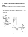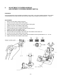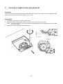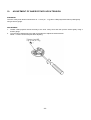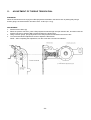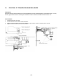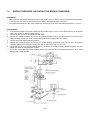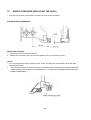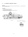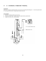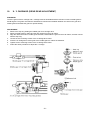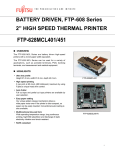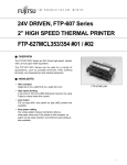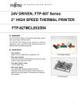
1
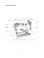
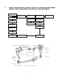
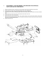
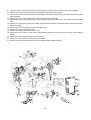
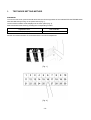
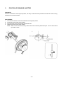
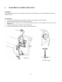
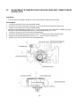
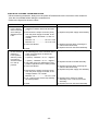
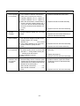
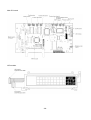
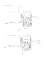
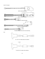
8. 2001.
• This service manual has been compiled for explaining the repair procedures for the PE-180D HOME
EMBROIDERY MACHINES.
• Use this service manual in conjunction with the Part List when you make a repair.
• This machine is manufactured based on product specifications which are current at the time of printing of this
manual. However, specifications are subject to change for improvement without notice, so contract the
manufacturer or your local sales agent for information regarding such changes.
Brother Industries, Ltd.
Nagoya, Japan
I. PRINCIPAL MECHANISMS.................................................................................... 2
II. DISASSEMBLY AND REASSEMBLY PROCEDURES.......................................... 8
III. ADJUSTMENT STANDARDS AND ADJUSTMENT PROCEDURES
FOR MECHANICAL PARTS................................................................................. 13
IV. PROBLEM DIAGNOSIS PROCEDURES FOR THE ELECTRONIC
SYSTEMS ............................................................................................................. 34
Most processes in the manufacturer of LSI devices such as microprocessors involve MOS (metal oxide
semiconductor) technology. It is thus necessary to take extreme care to prevent erasure or other damage caused
by static electricity during the use and manufacture of products using such LSI devices.
This embroidery machine is manufactured and assembled under a strictly controlled system preventing such
damage.
Similar care is also required during the service and maintenance of this product.
Please be sure to observe the following.
1.
2.
3.
4.
Always wear rubber gloves when handling the circuit boards. Never touch metal components with your bare
hands.
Ground your body to prevent static charge build-up.
When storing and shipping circuit boards, always wrap the circuit board in the specified aluminum foil
wrapper or equivalent static-prevention bag, and protect the circuit board from physical shock.
During adjustment and repair, do not touch or damage the circuit board with a screwdriver or other tool, and
do not touch the circuit-side of the board.
• The following symbols are used in this service manual.
-1-
1. MECHANICAL CHART .................................................................................... 3
2. POWER TRANSMISSION ASSEMBLY (VERTICAL NEEDLE BAR
MOVEMENT,THREAD TAKE-UP MOVEMENT AND ROTARY
HOOK MOVEMENT) ........................................................................................ 4
3. ELECTRONIC PARTS LAYOUT CHART ........................................................ 5
4. CONTROL SYSTEM BLOCK DIAGRAM ........................................................ 5
5. MAIN MOTOR CONTROL SYSTEM................................................................ 6
6. PATTERN GENERATOR ................................................................................. 6
7. OTHER ELECTRONIC COMPONENT FUNCTIONS ...................................... 7
-2-
1.
MECHANICAL CHART
-3-
2.
POWER TRANSMISSION ASSEMBLY (VERTICAL NEEDLE BAR MOVEMENT,
THREAD TAKE-UP MOVEMENT AND ROTARY HOOK MOVEMENT)
Thread take-up
lever
Thread take-up
Counter weight
Main shaft
Upper shaft gear
T pulley
Vertical shaft gear
Main motor
Vertical shaft
Needle bar crank
Needle bar crank
rod
Needle bar clamp
Vertical shaft pulley
Needle bar
Needle
Rotary hook
Timing belt
Rotary hook shaft pulley
-4-
Hand wheel
3.
ELECTRONIC PARTS LAYOUT CHART
4.
CONTROL SYSTEM BLOCK DIAGRAM
-5-
5.
MAIN MOTOR CONTROL SYSTEM
The main motor must operate at a constant speed regardless of load fluctuations, temperature fluctuations, or
other changes in operating conditions. The main motor is therefore driven by means of PWM (Pulse Width
Modulation) control.
6.
PATTERN GENERATOR
This embroidery machine stores the pattern data to memory, and drives the embroidery frame using the X and Y
pulse motors to produce the patterns. It is therefore possible to increase the number of stored patterns and the
total number of stitches by simply increasing the storage capacity of the embroidery machine.
Good positioning and response speed are also required of the pulse motors used in this machine because the
embroidery frame must be moved and stopped in a precise position while the need is up. A PM-type pulse motor
is therefore used with a simple open loop circuit configuration to drive the embroidery frame in this machine.
Pattern generator control block diagram
-6-
7.
OTHER ELECTRONIC COMPONENT FUNCTIONS
Start/stop switch ............................... Used to start and stop machine operation. When starting, the embroidery
machine operates at low speed as long as the switch is pressed. The need
will stop in the up position if pressed immediately after the "Raise needle"
error message is displayed.
Touch panel ....................................... Used to enter the pattern selection and other sewing conditions. The touch
panel replaces the conventional switches, and makes pattern selection
possible by simply touching the panel.
Presser switch ................................... Detects whether the presser lever is up or down.
Rotation sensor ................................. Detects the drive timing of the embroidery frame drive pulse motor and the
tension release solenoid and detects the vertical position of the needle. Also
detects the turning angle of the upper shaft by means of a photointerruptor
and shutter installed on the upper shaft.
Speed sensor ..................................... Detects the operating speed of the main motor by means of a photointerruptor
and shutter installed on the upper shaft.
Bobbin winder switch ....................... Detects whether the bobbin winder has been set when starting bobbin
winding.
Transformer ....................................... Used for pulse motor and solenoid drive, sew light power and for the
electronic circuit power supply.
Work light ........................................... Uses an 8-V, 2.4-W bulb to illuminate the presser foot area.
Tension release solenoid ................. Opens the tension disc to prevent the needle thread from becoming
tangled when forming long crossover threads.
-7-
1. DISASSEMBLY AND REASSEMBLY PROCEDURES FOR EXTERNAL
PARTS AND MAJOR COMPONENTS ........................................................... 9
2. SECURING THE LEADS................................................................................ 12
-8-
1.
1.
2.
3.
4.
5.
6.
7.
8.
DISASSEMBLY AND REASSEMBLY PROCEDURES FOR EXTERNAL
PARTS AND MAJOR COMPONENTS
Raise the presser foot lever, remove the screw, and then remove the face plate from the left side.
Remove the two screws of the needle plate and then lift out the needle plate.
Loosen the screw of the X carriage cover and then remove the X carriage cover.
Remove the four screws of the bottom plate and the two screws of the cover, and then remove the bottom
plate.
Remove the four screws of the rear cover and then remove the rear cover.
Remove the main cover to the left side.
Remove the four screws of the front cover. Then remove the front cover from the lower section of the thread
path cover and the part around the tension control dial in that order, and then disconnect the three electrical
connectors to remove the front cover.
Remove the belt cover.
-9-
9. Disconnect the 13 electrical connectors, remove the two screws, and then remove the main PC board.
10. Remove the screws and then remove the embroidery presser foot and needle.
11. Remove the two screws of the thread path assembly, remove the tension spring, and then remove the thread
path assembly.
12. Remove the two screws and then remove the solenoid holder assembly.
13. Remove the screw of the main motor cover and then remove the main motor cover. (220 to 240 V models
only)
14. Remove the two screws of the motor holder, disconnect the electrical connectors and then remove the motor
holder assembly.
15. Remove the screws and then remove the shutter cover.
16. Remove the screw of the back cover.
17. Remove the three screws of the fixation unit.
18. Remove the two screws of the upper shaft bushing fixation and then remove the upper shaft bushing
fixation.
19. Remove the main shaft assembly and presser unit.
20. Remove the two screws and then remove the handle.
21. Remove the two screws and then remove the bobbin winder holder assembly.
- 10 -
22.
23.
24.
25.
26.
27.
28.
29.
Remove the two screws of the bushing fixation and then remove the vertical shaft.
Remove the three screws of the rotary hook shaft frame assembly and then remove the rotary hook unit.
Remove the screw and then remove the circuit board mounting plate.
Remove the three screws and then remove the power supply unit cover.
Remove the screw and then remove the switch holder.
Remove the three screws and then remove the power supply unit.
Remove the four screws and then remove the main frame.
Remove the two screws and then remove the inlet assembly.
- 11 -
2.
SECURING THE LEADS
Please note the following.
1. Be sure the LCD module leads are not pinched by the handle when passed through the shutter cover and
the handle is lifted.
2. The sew light leads from the power supply PC board extend to the front from the right side of the main PC
board amount of the bobbin winder holder.
3. The leads coming from the power supply PC board pass under the cord holder of the power supply unit and
out to the front.
4. (For 220 – 240 V specifications only)
Pass the cord for the main motor under the main motor cover so that it will not directly touch the main motor.
- 12 -
1.
2.
3.
4.
5.
6.
7.
8.
9.
10.
11.
12.
13.
14.
15.
16.
17.
18.
19.
20.
TEST MODE SETTING METHOD.................................................................. 14
TENSION OF MOTOR DRIVE BELT AND ROTARY HOOK SHAFT BELT. 15
POSITION OF SENSOR SHUTTER .............................................................. 16
ADJUSTMENT OF NEEDLE DROP POINT .................................................. 17
CLEARANCE BETWEEN NEEDLE AND ROTARY HOOK POINT
AND LOOP LIFT ............................................................................................ 18
HEIGHT OF NEEDLE BAR ............................................................................ 19
ADJUSTMENT OF THREAD TAKE-UP SPRING
(ADJUSTMENT OF THREAD BREAKAGE SHUTTER)................................ 20
ADJUSTMENT OF BOBBIN WINDING
(ADJUSTMENT OF BOBBIN WINDER SWITCH) ......................................... 21
POSITION OF INNER ROTARY HOOK BRACKET ...................................... 22
ADJUSTMENT OF INNER ROTARY HOOK TENSION ................................ 23
ADJUSTMENT OF TREAD TENSION DIAL.................................................. 24
POSITION OF TENSION RELEASE SOLENOID.......................................... 25
NEEDLE THREADER .................................................................................... 26
NEEDLE THREADER (ADJUSTMENT OF NEEDLE THREADER).............. 27
NEEDLE THREADER (REPLACEMENT OF HOOK).................................... 28
X-Y CARRIAGE (X TIMING BELT TENSION) ............................................... 29
X-Y CARRIAGE (Y TIMING BELT TENSION) ............................................... 30
X-Y CARRIAGE (DRIVE GEAR ADJUSTMENT)........................................... 31
X-Y CARRIAGE (X CARRIAGE POSITION).................................................. 32
ADJUSTMENT OF INNER ROTARY HOOK HOLDER AND
LOWER THREAD GUIDE PLATE ................................................................. 33
- 13 -
1.
TEST MODE SETTING METHOD
STANDARD
To enter the test mode, press and hold down both the left and right sides of the CHARACTER PATTERNS button
while simultaneously turning on the power switch (Fig. 1).
The test mode numbers will be displayed in the touch panel (Fig. 2).
Select the desired test mode by pressing the corresponding number.
Adjustment item
Test mode No.
Thread take-up spring adjustment
26
All other test mode numbers are reserved and are not used for adjustment.
[Fig. 1]
[Fig. 2]
- 14 -
2.
TENSION OF MOTOR DRIVE BELT AND ROTARY HOOK SHAFT BELT
STANDARD
Motor belt tension: The belt should move in by 5 - 7 mm when a force of approximately 2 N (200 g) is applied
midway between the drive pulley and motor shaft. Rotary hook shaft belt tension: The belt should move in by 6 - 8
mm when a force of approximately 2 N (200 g) is applied midway between the rotary hook shaft pulley and
vertical shaft pulley.
ADJUSTMENT
1.
2.
3.
4.
5.
6.
Loosen the two screws of the motor holder.
Move the motor holder to adjust the belt deflection to 5 - 7 mm.
Tighten the two screws of the motor holder.
Slightly loosen the screw of the eccentric shaft.
Turn the eccentric shaft right or left to adjust the belt deflection to 6 - 8 mm.
Tighten the screw of the eccentric shaft.
- 15 -
3.
POSITION OF SENSOR SHUTTER
STANDARD
When the needle bar is at its highest position, the rotary shutter should be positioned so that the screw is facing
toward the front of the machine.
ADJUSTMENT
1.
2.
3.
4.
Turn the hand wheel to raise the needle bar to its highest position.
Loosen the screw of the rotary shutter.
Turn the screw of the rotary shutter toward the front.
Tighten the screw of the rotary shutter.
NOTE : Make sure the side of the rotary shutter does not contact the photointerrupter. Turn the hand wheel
by hand to check.
- 16 -
4.
ADJUSTMENT OF NEEDLE DROP POINT
STANDARD
The needle should enter 0.9 mm inward from the left end of the needle hole in the needle plate when the hand
wheel is turned.
ADJUSTMENT
1.
2.
3.
4.
5.
Turn the hand wheel by hand and observe the position of the needle in the needle hole.
Loosen the screw and the set screw of the presser unit.
Move the presser unit right or left so that the needle point locates 0.9 mm inward from the left end of the
needle hole.
Tighten the screw and the set screw of the presser unit.
Turn the hand wheel by hand and recheck the needle drop point.
- 17 -
5.
CLEARANCE BETWEEN NEEDLE AND ROTARY HOOK POINT AND LOOP LIFT
STANDARD
When the needle is raised 2.2 - 2.6 mm from its lowest position, the rotary hook point should be at the side of the
needle. The gap between the needle (75/11) and rotary hook point at this time should be less than 0.1 mm with
no contact between the rotary hook point and the needle.
ADJUSTMENT
* Remove the inner rotary hook before adjusting.
1. Loosen the two set screws of the rotary hook pulley.
2. Adjust so that the rotary hook should be at the side of the needle when the needle is raised 2.2 - 2.6 mm
from its lowest position.
3. Tighten the two set screws of the rotary hook pulley.
4. Loosen the screw.
5. Turn the set screw in or out so that the clearance between the needle and the rotary hook point is less than
0.1 mm.
6. Tighten the screw.
- 18 -
6.
HEIGHT OF NEEDLE BAR
STANDARD
The distance from the top edge of the needle eye to the bottom of the rotary hook point should be 1.6 - 2.0 mm
when the rotary hook point is at the side of the needle by turning the hand wheel.
ADJUSTMENT
1.
2.
3.
4.
Turn the hand wheel so that the rotary hook point is at the closest point to the needle.
Loosen the set screw of the needle bar clamp.
Move the needle bar up or down to adjust the gap to 1.6 - 2.0 mm.
Tighten the set screw of the needle bar clamp.
NOTE : The needle bar can turn easily when adjusting the needle bar height, possibly resulting in sewing
problems. Make sure the needle clamp is properly aligned when the adjustment is completed.
- 19 -
7.
ADJUSTMENT OF THREAD TAKE-UP SPRING
(ADJUSTMENT OF THREAD BREAKAGE SHUTTER)
STANDARD
When the thread take-up spring stroke is 8 - 9 mm and test mode 26 is selected, the buzzer should sound when
the thread take-up spring is raised 4 - 5 mm from the down position.
ADJUSTMENT
1.
2.
3.
4.
5.
6.
7.
Select test mode 26.
Loosen the screw of the thread take-up spring cover.
Turn the thread take-up spring cover to adjust the thread take-up spring stroke to 8 - 9 mm.
Tighten the screw of the thread take-up spring cover.
Loosen the screw of the thread breakage sensor PC board.
Lift the thread take-up spring and adjust the sensor PC board so that the buzzer sounds when the thread
take-up spring is raised 4 - 5 mm from its lowest position.
Tighten the screw of the thread breakage sensor PC board.
- 20 -
8.
ADJUSTMENT OF BOBBIN WINDING
(ADJUSTMENT OF BOBBIN WINDER SWITCH)
STANDARD
The thread should be wound parallel to the bobbin core to 85% - 90% of the outside diameter of the bobbin.
The gap between the bobbin winder switch and the bobbin winder spindle base should be 0.5 - 1.0 mm.
ADJUSTMENT
1.
2.
3.
4.
5.
6.
7.
8.
9.
10.
11.
12.
Remove the face plate. (Refer to page 9.)
Loosen the screw of the bobbin winder guide.
Adjust the bobbin winding by moving the bobbin winder guide.
Tighten the screw of the bobbin winder guide.
Slightly loosen the screw of the bobbin presser.
Turn the bobbin presser to adjust the bobbin winding amount.
Tighten the screw of the bobbin presser.
Remove the rear cover. (Refer to page 9.)
Set the bobbin winder spindle to the left and turn the bobbin winder switch off.
Loosen the screw of the bobbin winder switch.
Adjust the gap between the bobbin winder switch and bobbin winder spindle base to 0.5 - 1.0 mm.
Tighten the screw of the bobbin winder switch.
- 21 -
9.
POSITION OF INNER ROTARY HOOK BRACKET
STANDARD
When the inner rotary hook bracket and the rotary hook meet, the spring of the inner rotary hook bracket and the
inner rotary hook should overlap each other by 1.9 - 2.1 mm.
ADJUSTMENT
1.
2.
3.
Loosen the screw of the inner rotary hook bracket.
Adjust the forward-backward and sideways positions of the inner rotary hook bracket.
NOTE : Surface A of the inner rotary hook should be parallel to the front of the embroidery machine (parallel
to the upper shaft).
Tighten the screw of the inner rotary hook bracket.
- 22 -
10.
ADJUSTMENT OF INNER ROTARY HOOK TENSION
STANDARD
The inner rotary hook tension should be 0.12 - 0.14 N (12 - 14 g) when a #90 polyester thread is pulled gently
using a tension gauge.
ADJUSTMENT
1.
2.
Thread a #90 polyester thread normally to the inner rotary hook and then pull the thread gently using a
tension gauge.
Turn the spring adjustment screw with a screwdriver to adjust the thread tension.
NOTE : Lock the screw with paint after adjusting.
- 23 -
11.
ADJUSTMENT OF THREAD TENSION DIAL
STANDARD
When the tension dial is set to [5] and a #60 polyester thread held in the tension disc is pulled gently using a
tension gauge, the thread tension should be 0.23 - 0.26 N (23 - 26 g).
ADJUSTMENT
1.
2.
3.
4.
Set the tension dial to [5].
Raise the presser foot lever, pass a #60 polyester thread through the open tension disc, and then lower the
presser foot lever to hold the #60 polyester thread in the tension disc.
Using a tension gauge, pull gently down on the #60 polyester thread held in the tension disc.
Turn the thread tension adjustment screw to adjust the dial tension.
NOTE : After completing the adjustment, lock the screw with a screw lock adhesive.
- 24 -
12.
POSITION OF TENSION RELEASE SOLENOID
STANDARD
When the tension release solenoid is off, the gap between tension release plates A and B should be 0 - 0.5 mm,
and the gap between tension release plate A and the tension release solenoid shaft should be 0 mm.
ADJUSTMENT
1.
2.
3.
4.
Lower the presser foot lever.
Loosen the two screws of the solenoid holder.
Shift the solenoid holder right or left to adjust the gap between tension release plate A and B.
Tighten the two screws of the solenoid holder.
- 25 -
13.
NEEDLE THREADER
USING THE NEEDLE THREADER
The provided needle threader can be used with sewing machine needle sizes 75/11 to 100/16.
A 75/11 needle is standard when embroidering, but a 90/14 needle is recommended when working with thick
material.
OTHER PRECAUTIONS
1.
2.
3.
4.
Be sure the embroidery presser foot is down when operating the needle threader.
Do not turn the hand wheel when using the needle threader.
Do not lower the needle threader lever when using the machine.
This could break the needle threader, making it unusable and possibly causing needle breakage or harm to
the operator.
If the needle is not at least 7 mm above the top of the needle plate, it can not thread the needle using the
needle threader.
- 26 -
14.
NEEDLE THREADER (ADJUSTING THE NEEDLE THREADER)
STANDARD
• When the hook has passed through the hole of the needle (75/11 or 80/12), the hook should be in the middle
of the hole with the same clearances between it and the left and right sides of the hole.
• The clearance between the top of the needle hole and the top of the hook at this time should be 0 – 0.1 mm.
ADJUSTMENT
1.
2.
3.
4.
5.
6.
*
Turn the hand wheel to raise the needle until the needle point is 7 mm or more above the top of the needle
plate. (Use a 75/11 or 80/12 needle for this.)
Loosen the two screws of the needle threader base.
Operate the needle threader, and move the needle threader base to the right and left so that the hook
passes exactly through the center of the needle hole, and then tighten the two screws.
Loosen the screw of the positioning support.
Operate the needle threader, and move the needle threader positioning guide up and down so that the
clearance between the top of the needle hole and the top of the hook is 0 - 0.1 mm.
Check that part A of the needle threader base is parallel to the needle threader positioning guide, and then
tighten the screw of the positioning support.
If they are not parallel, the needle threader positioning guide will hit the needle threader base, which could
damage the needle threader.
- 27 -
15.
NEEDLE THREADER (REPLACING THE HOOK)
• If the point of the hook becomes bent or broken, the hook must be replaced.
STANDARD HOOK DIMENSIONS
REPLACING THE HOOK
1.
2.
Remove the two hook mounting screws.
Replace the hook with a new one, and then tighten the two hook mounting screws.
Caution
• Do not over-tighten the hook mounting screws, as this could strip the screw threads, which will make
tightening impossible.
3. If the hook doesn’t pass correctly through the needle hole after the hook has been replaced, adjust the
needle threader position. (Refer to "ADJUSTMENT" in "14. NEEDLE THREADER (ADJUSTING THE
NEEDLE THREADER).")
- 28 -
16.
X - Y CARRIAGE (X TIMING BELT TENSION)
STANDARD
When the X carriage is positioned all the way to the left, the timing belt should give 2 - 4 mm when pressed with a
1N (100 g) load midway of the belt.
ADJUSTMENT
1.
2.
3.
4.
Move the X carriage all the way to the left.
Loosen the screw of the X tension pulley.
Adjust the position of the X tension pulley with the adjustment screw.
Tighten the screw of the X tension pulley.
- 29 -
17.
X - Y CARRIAGE (Y TIMING BELT TENSION)
STANDARD
When the Y carriage is positioned all the way to the front, the timing belt should give 2 - 4 mm when pressed with
a 1 N (100 g) load from the X carriage body measurement hole.
ADJUSTMENT
1.
2.
3.
Move the Y carriage all the way to the front.
Loosen the screw of the Y tension pulley and adjust the timing belt tension.
Tighten the screw of the Y tension pulley.
- 30 -
18.
X - Y CARRIAGE (DRIVE GEAR ADJUSTMENT)
STANDARD
The drive gears of the X carriage and Y carriage must be assembled with the reference holes in middle gears A
and B aligned. The gears must also be assembled to minimize the backlash between the drive motor gear and
middle gears and enable the gears to operate silently.
ADJUSTMENT
1.
2.
3.
4.
5.
6.
7.
Remove the stop ring holding the middle gear for X carriage drive.
Remove middle gears A and B and the gear spring from the main frame.
Align the reference holes in middle gears A and B, reassemble the gears to the main frame, and then secure
with the stop ring.
Loosen the two mounting screws of the X carriage drive motor.
Press the X carriage drive motor gear to the middle gears to reduce the backlash.
Tighten the two mounting screws of the X carriage drive motor.
Follow the same procedure to adjust the Y carriage.
- 31 -
19.
X - Y CARRIAGE (X CARRIAGE POSITION)
STANDARD
The X carriage must be installed perpendicularly to the embroidery machine arm (upper shaft).
Select the pre-programmed "frame pattern (square border)", enlarge the size to maximum, and then touch the
"TRIAL" to move the embroidery frame: the embroidery presser foot should not contact the inside of the
embroidery frame at anywhere.
ADJUSTMENT
1.
2.
3.
4.
5.
Loosen the three mounting screws of the X carriage.
Move the X carriage right or left so that the X carriage is perpendicular to the upper shaft.
Tighten the three mounting screws of the X carriage.
Stretch a piece of felt in the embroidery frame and then set the frame in the embroidery machine.
Select the preprogrammed "frame pattern (square border)", enlarge the size to maximum, and then touch
the "TRIAL" to move the embroidery frame. Confirm that the embroidery presser foot does not contact the
inside of the embroidery frame at anywhere.
- 32 -
20.
ADJUSTMENT OF INNER ROTARY HOOK HOLDER AND LOWER THREAD
GUIDE PLATE
STANDARD
• The inner rotary hook holder should be 27.3±0.2 mm above the rotary hook shaft frame.
ADJUSTMENT
1. Loosen the mounting screw of the fixed blade holder.
2. Move the inner rotary hook holder so that it is 27.3±0.2 mm above the rotary hook shaft frame.
3. Tighten the mounting screw of the fixed blade holder.
0
• The lower thread guide plate should be 29.4 - 0.3 mm above the rotary hook shaft frame. In addition, the gap
between the lower thread guide plate and inner rotary hook should be 1.5 + 0.40 mm.
4. Loosen the mounting screw of the lower thread guide plate.
0
5. Move the lower thread guide plate so that it is 29.4 - 0.3 mm above the rotary hook shaft frame.
+ 0.4
6. Move the lower thread guide plate so that it is 1.5 0 mm from the inner rotary hook.
7. Tighten the mounting screw of the lower thread guide plate.
- 33 -
1. POWER IS ON BUT THE BUZZER DOES NOT SOUND AND NOTHING
IS DISPLAYED ON THE LCD. ....................................................................... 35
2. PULSE MOTORS DO NOT CORRECTLY DETECT THE HOME
POSITION AFTER THE POWER IS TURNED ON AND THE NEEDLE
IS IN THE UP POSITION. .............................................................................. 35
3. PATTERN SELECTION IS NOT POSSIBLE. ................................................ 36
4. MAIN MOTOR DOES NOT OPERATE. ......................................................... 36
5. MAIN MOTOR OPERATES UNEVENLY. ...................................................... 36
6. EMBROIDERY FRAME OPERATION IS NOT NORMAL.............................. 37
7. LCD DOES NOT OPERATE NORMALLY. .................................................... 37
8. LCD BACKLIGHT DOES NOT WORK .......................................................... 37
9. BOBBIN WINDING IS NOT POSSIBLE. ....................................................... 37
10. NEEDLE THREAD DETECTION DOES NOT OPERATE NORMALLY. ....... 37
- 34 -
ELECTRICAL SYSTEMS TROUBLESHOOTING
* When measuring resistance, always turn the power off and disconnect the connector to be measured
from the circuit board before taking the measurement.
* Refer to the figures for where to check.
CONDITION
PROBLEM SYMPTOMS
1. Power is ON
1) When the power switch is ON, is the
but the buzzer
resistance between both ends less than
does not sound
1 Ω?
and nothing is 2) Disconnect the output connector (CN1)
displayed in the
from the power supply PC board; is the
LCD.
voltage between terminals 1-2, and 3-4
normal?
Between 1-2 ......................24 to 31 V DC
Between 3-4 ......................13 to 18 V DC
3) Is the fuse blown?
COUNTERMEASURES
1) Replace the power supply unit assembly.
2) Replace the power supply unit assembly.
3) Replace the fuse (after correcting the
cause of the blown fuse).
4) Replace the main PC board assembly.
4) Other
2. Pulse motors
1) Replace the defective pulse motor.
1) Is there the normal resistance between
do not correctly
the following pins of the connector of the
detect the
pulse motor that does not detect the
home position
home position?
after the power
X (CN16)....Between 1-2, 3-4 → Approx.Ω
is turned on
Y (CN17)....Between 1-2, 3-4 → Approx.Ω
and the needle
2) Replace the NP PC board assembly.
2)
The pulse motor only detects the home
is in the up
position
regardless
of
the
needle
position.
position.
3) Replace the fuse (after correcting the
3) Is the fuse blown?
cause of the blown fuse).
4)
Replace the power supply unit assembly.
4) Disconnect the output connector (CN1)
from the power supply PC board; is the
voltage between 1-2 normal?
Between 1-2 ......................24 to 31 V DC
5) Replace the X sensor PC board
5) X or Y pulse motor will not stop seeking
assembly or the Y sensor PC board
the home position.
assembly.
6) Replace the main PC board assembly.
6) Other
- 35 -
CONDITION
3. Pattern
selection is not
possible.
4. Main motor
does not
operate.
5. Main motor
operates
unevenly.
PROBLEM SYMPTOMS
1) Is the start/stop switch stuck?
2) Other
1) Does the hand wheel turn easily?
2) Is the main motor assembly connector
(power supply unit connector CN1)
correctly connected?
3) Is the resistance between the terminals of
the main motor assembly normal?
For 120 V models ................ 120 to 180 Ω
For 230 V models ................ 400 to 800 Ω
4) Is the start/stop switch normal?
Resistance between both switch sides:
When switch is pressed .... less than 1 Ω
When switch is released ........ ∞ (infinite)
5) Is the presser foot lever down? Is the
presser switch normal?
Resistance between both sides of CN8
Presser foot is up .............. less than 1 Ω
Presser foot is down............... ∞ (infinite)
6) Other
COUNTERMEASURES
1) Correct, or replace the SS PC board
assembly.
2) Replace the LCD module assembly.
1) Correct installation so hand wheel turns
easily.
2) Confirm connection.
3) Replace the main motor assembly.
4) Replace the SS PC board assembly.
5) Confirm the presser switch installation; if
the problem remains, replace the
presser switch.
6) Replace the main PC board assembly or
the power supply unit assembly.
1) Replace the NP PC board assembly.
1) When the hand wheel is rotated slowly in
reverse, does the voltage between 2-5, 35 and 4-5 in the NP PC board assembly
connector (CN10) fluctuate between 0 to
5 V DC?
2) Other
2) Replace the main PC board assembly.
- 36 -
CONDITION
PROBLEM SYMPTOMS
6. Embroidery
1) Is the rotary shutter correctly positioned?
frame operation 2) Is the resistance between the following
is not normal.
pulse motor connector pins normal?
X (CN16).. Between 1-2, 3-4 → Approx. 3 Ω
Y (CN17).. Between 1-2, 3-4 → Approx. 4 Ω
3) When the hand wheel is rotated slowly in
reverse, does the voltage between 2-5, 35 and 4-5 in the NP PC board assembly
connector (CN10) fluctuate between 0 to
5 V DC?
4) Other
7. LCD does not
1) Is the voltage between 8-7 in the LCD
operate
module connector (CN5) -5 to -10 V DC?
normally.
2) Other
8. LCD backlight
does not work.
1) Disconnect the output connector (CN1)
from the power supply PC board; is the
voltage between 3-4 normal?
Between 3-4 .......................13 to 18 V DC
2) Is the voltage between 9-10 of the LCD
module connector (CN5) 9V DC?
3) Other
9. Bobbin winding 1) Is the resistance between both sides of
is not possible.
the bobbin winder switch connector (CN4)
less than 1 Ω during bobbin winding and
∞ (infinite) at all other times?
2) Is the installation correct?
3) Other
10.Needle thread 1) Is the voltage between 2-3 to the needle
detection does
thread breakage sensor connector (CN9)
not operate
normal when the thread is tensioned and
normally.
released with the needle thread correctly
threaded in the thread path?
When thread is tensioned ............... 0 V Ω
When thread is released ................. 5 V Ω
2) Other
- 37 -
COUNTERMEASURES
1) Adjust (see page 16.)
2) Replace the defective pulse motor.
3) Replace the NP PC board assembly.
4) Replace the main PC board assembly.
1) Replace the main PC board assembly.
2) Replace the LCD module assembly or
the main PC board assembly.
1) Replace the power supply unit assembly.
2) Replace the main PC board assembly.
3) Replace the LCD module assembly.
1) Replace the bobbin winder switch
assembly.
2) Adjust (see page 21).
3) Replace the main PC board assembly.
1) Adjust the thread take-up spring; if the
problem remains, replace the thread
breakage sensor PC board assembly
(see p.20).
2) Replace the main PC board assembly.
Main PC board
LCD module
- 38 -
Power supply PC board
For 120V AC models
For 230 V AC models
- 39 -
Main motor assembly
For 120 V AC models without insulation
For 230 V AC models with insulation
- 40 -
Other PC boards
SS PC board assembly
NP PC board assembly
Y sensor PC board assembly
X sensor PC board assembly
Thread breakage sensor PC board assembly
Inlet
For 120 V AC models without insulation
For 230 V AC models with insulation
- 41 -
PE-180D
H1060205