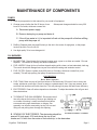
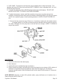
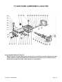
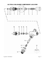
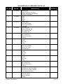
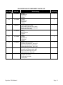
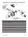
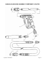
1
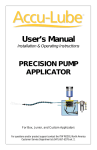
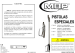
Pressure Washers
and Accessories
EQUALIZER 3200
(PN 9490A-E)
Operators Manual
and Parts Lists
Delco Pressure Washers LIT-EQ3200-DEL
Equalizer 3200 Manual
Page 1
INTRODUCTION
Thank you for selecting a high pressure power washer from Delco Pressure Washers.
Your pressure washer has been manufactured using the most advanced components in the
pressure industry.
When operated properly, our equipment has been designed and manufactured to give you years
of trouble free, reliable use, with a minimal amount of regular maintenance.
Your pressure washer is mechanical, as with all mechanical equipment it requires proper
installation, operation and maintenance as outlined in this manual.
The Operators Manual has been written for your benefit. For your safety and the safety of
others, we recommend you and all operators read and understand the contents.
Should you experience any difficulty with your Delco pressure washer, please contact your
nearest Delco Distributor immediately.
We are aware of your investment in an Delco pressure washer, therefore, our prime concern is
that you become one of our “satisfied” owners. Please feel free to send us your comments and
ideas.
THANK YOU!!!
Equalizer 3200 Manual
Page 2
PRESSURE WASHER LIMITED WARRANTY
1. DELCO® Cleaning Systems, LLC warrants its products for a period of one year from the date of
purchase, against defects in material and/or workmanship. The warranty covers parts and labor,
but excludes transportation.
2. Normal wear and tear items such as valves, seals, etc., are warranted for the initial 30 days
following purchase by the end-user.
3. The high-pressure hose and accessories (trigger gun, extension/lance/wand and cleaning
nozzles) are warranted for the initial 30 days following purchase by the end-user.
4. The burner coil on all DELCO® Cleaning Systems, LLC, hot water pressure washers and steam
cleaners is warranted for five (5) years, excluding abuse due to leaving unit in unheated building,
causing coil to freeze and burst.
5. Parts repaired or replaced under this warranty (except wear items) are warranted for the balance
of the original warranty period or ninety (90) days, whichever is longer. Defective parts replaced
under this warranty are the property of DELCO® Cleaning Systems, LLC.
6. All warranty service will be performed by a trained technician employed by an Phoenix Cleaning
Systems, LLC distributor/dealer. Servicing distributor/dealer will abide by the DELCO® Cleaning
Systems, LLC, Service Center Warranty Policy.
7. Warranty does not cover damage caused by freezing, abuse or chemicals. Abuse includes but is
not limited to unauthorized repair, alterations carried out by any entity or individuals other than
DELCO® Cleaning Systems, LLC, authorized service personnel, damage caused by
contaminants in the water supply or operation in a manner which conflicts with instructions found
in the Owners Manual.
8. DELCO® Cleaning Systems, LLC, and its distributors/dealers disclaim responsibility for any loss
of time, use of equipment, loss of income, or any incidental or consequential damages.
9. Settlement of any warranty claim will be at the sole discretion of DELCO® Cleaning Systems,
LLC.
Thank You for Purchasing our Products!
Effective January, 2005, and supersedes all other warranties.
Equalizer 3200 Manual
Page 3
IMPORTANT SAFETY PRECAUTIONS
IMPORTANT:
Please read the following instructions before installing and operating this equipment.
DANGER
THIS EQUIPMENT CAN BE HAZARDOUS TO OPERATOR SAFETY AND ONLY AUTHORIZED
PERSONNEL WHO HAVE READ AND UNDERSTAND THE INSTALLATION AND OPERATION
MANUAL SHOULD
BE PERMITTED TO OPERATE THIS EQUIPMENT. DO NOT LEAVE WAND UNATTENDED
WHILE EQUIPMENT IS RUNNING.
Failure to follow all cautionary warnings and procedures may result in serious or fatal injury and/or
property damage including, but not limited to: fire, severe burns, concussion from explosion,
electrocution, scalding, penetration by pressurized water, chemical reaction, asphyxiation, cuts,
contusions, laceration, and loss of body parts and/or life.
DO’S
1. ALWAYS WEAR SAFETY GLASSES, GOGGLES or FULL FACE SHIELD; GLOVES, and when
spraying acids WEAR RAIN GEAR. NEVER RUN ACIDS THROUGH THE PUMP ON THIS
EQUIPMENT.
2. USE ONLY THE SAME SIZE NOZZLE SUPPLIED WITH THIS EQUIPMENT.
3. CHECK YOUR BATTERY FOR WATER LEVELS AND MAINTAIN A GOOD CHARGE.
4. USE ¾" (inch) x 50' (foot) GARDEN HOSE FOR WATER SUPPLY-.
5. USE A CLEAN FUEL CAN FOR REFUELING UNIT.
6. USE CLEAN DIESEL FUEL OR KEROSENE. NO ADDITIVES. Fill fuel tank each evening. This
will help minimize condensation in fuel tank, and prolong fuel pump life.
7. Always follow chemical manufacturer’s recommendations in use of chemicals with this
equipment. Immediately after using chemical solutions through this equipment, flush thoroughly
with clear water.
8. Disconnect all electrical power before performing any maintenance on this equipment.
9. Make sure positive is always positive and negative is always negative to keep from shorting out.
10. When storing this equipment in freezing weather conditions, this equipment must be drained
thoroughly; and the plumbing system charged with a 50% solution of permanent type antifreeze.
Antifreeze should be used when the equipment is not in service for prolonged periods or is being
transported in freezing weather. NOTE: Antifreeze must be flushed out of equipment thoroughly
before any cleaning project begins. Failure to do so could result in damage to paint or chemical
attack on painted surfaces.
11. Use a water softener on your water system if it is high in mineral content (HARDNESS). Failure
to do so will result in lime build-up in plumbing systems.
12. Use only manufacturer approved components when replacing parts on this equipment. Failure
to do so may create operating conditions that are hazardous to personal health, safety, and will
void the warranty.
13. Use only recommended oil in pump.
Equalizer 3200 Manual
Page 4
14. Always cool down coil.
DO NOT’S
DO NOT - UNDER ANY CIRCUMSTANCES - POINT THE HIGH PRESSURE NOZZLE AT
YOURSELF, OTHER PEOPLE, OR ANIMALS!
1. DO NOT use an undersized discharge nozzle.
2. DO NOT disconnect the pressure hoses or wand while the equipment is HOT, PRESSURIZED or
RUNNING.
3. DO NOT operate this equipment without sufficient water supply to the pump.
4. DO NOT operate this equipment without proper ventilation or in a closed space.
5. DO NOT use any type of fuel other than # 2 diesel, kerosene or # 1 home heating oil.
6. DO NOT leave wand unattended while equipment is running.
7. DO NOT point the stream of water from nozzle toward any person or animal (including the
operator).
8. DO NOT touch exhaust stack, metal wand and hose on HOT WATER UNIT. THEY GET VERY
HOT!
9. DO NOT obstruct the exhaust stack.
10. DO NOT run engine or burner within 25 feet of flammable materials or dust.
11. DO NOT use this equipment around or near explosive environment of any kind. (Gas, paint,
solvents, etc.)
12. DO NOT screw the pop-off valve all the way in to prevent leaking or dripping.
13. DO NOT adjust the unloader-regulator valve (on trigger control units) to a pressure in excess of
200 PSI of equipments motor or pump rating.
14. DO NOT secure trigger gun in the open position (ON). Operate ONLY with your hand during
operation to prevent injury.
15. DO NOT allow air into the water system through soap valve or loose fittings.
16. DO NOT operate the machine if the water pressure drops or is low.
17. DO NOT continue to operate this machine if burner fails to shut off when trigger is released
(closed).
18. DO NOT continue to operate this machine if burner fails to light.
19. DO NOT smoke or operate this machine while filling or emptying fuel tank(s), or
connecting/disconnecting tanks and fittings.
20. DO NOT operate this machine if coil becomes clogged or soothed.
21. DO NOT alter machine from manufacturer’s design.
22. DO NOT attempt to pull beyond normal length.
23. DO NOT attempt to service this machine without first disconnecting the electrical service. Failure
to do so may cause severe or fatal electrical shock.
24. DO NOT BY-PASS ANY SAFETY DEVICE ON THIS MACHINE!
Equalizer 3200 Manual
Page 5
INSTALLATION
1. LOCATION
Avoid operating units in small areas or near exhaust fans. Adequate oxygen is needed for combustion
or dangerous carbon monoxide will result. Stationary units should be installed in accordance with local
plumbing and heating codes.
2. FUEL SUPPLY
Oil Fired Units: Fill fuel tank with clean kerosene, No. 1 home heating fuel, or diesel fuel (without
anti-gel additives.)
3. VENTING THE UNITS If the unit is to be used in an enclosed area it must be vented out.
The Draft Regulator (on oil-fired units) and chimney must be
same size as the stack on the cleaner unit. Poor draft will cause
the unit to soot-up and not operate efficiently. When installing
the machine so the stack will be as straight as possible,
protruding through the roof at a sufficient height to eliminate
down-draft and to comply with local codes.
Always disconnect the battery when servicing your cleaner.
Equalizer 3200 Manual
Page 6
OPERATING THE MACHINE
PRE-OPERATING INSTRUCTIONS
1. Connect the swivel end of the discharge hose to the cleaning gun.
2. Attach the hose to the machine outlet.
3. Check the fuel level in the fuel tank. Add fuel if required. It is best to keep fuel tank full during
nonworking conditions.
4. Attach an ordinary garden hose to the float tank inlet. Turn on the water supply and let the float
tank fill.
5. Place the end of the soap line into your soap solution container.
OPERATING INSTRUCTIONS
NOTE: On initial start up, or if machine has not been operated for several days, it is advisable to
remove the nozzle from the cleaning gun and flush out any foreign material. Open the water supply.
Turn on the engine and let the unit run until clear water flows through the cleaning gun.
1. Turn on the water supply.
2. Add fuel if required. Check oil levels in pump and engine before starting.
3. Install the nozzle tip into the cleaning gun.
4. Close the soap valve. (turn fully clockwise)
5. Securely hold the cleaning gun and turn the switch to position 1(pump).
6. The recommended method of cleaning is:
A. Wet entire surface and remove the loose dirt with water only,
B. Turn on the soap by opening the soap valve (turn the handle counterclockwise). NOTE: The
operating pressure of the machine will drop to nearly zero until the soap line is primed.
C. Cover the entire surface to be cleaned with soap/water solution by applying from the bottom
up. Allow the soap to stay on surface four to five minutes.
D. Close the soap valve and wash at high pressure with water only from the top down.
NOTE: Soap will flush from the coil and discharge hose within a minute or two of operation.
E. For hot water washing, turn the switch to position 2 (burner). CAUTION: If there is a sudden loss
of pressure while washing with hot water, turn the burner off immediately and attempt to locate
the problem while running cold water only. Failure to turn the burner off could cause excessive
temperature and pressure build-up in the heating coil.
Equalizer 3200 Manual
Page 7
SHUT DOWN INSTRUCTIONS
1. If the burner is on turn control switch to position 1(pump).
2. Run water through the pump until cool water flows from the cleaning gun. Failure to do this could
result in increased coil scaling.
3. Turn the control switch to off.
4. Turn off the water supply.
5. If the machine will be exposed to freezing temperatures, see winterizing procedure.
THINGS TO CHECK DAILY
1. Check oil level in pump.
2. Fill fuel tank at the end of each day’s use to prevent condensation build-up in fuel system.
3. Fill soap container.
4. Check oil level in engine.
THINGS TO CHECK WEEKLY
1. Check and clean water float tank and pump inlet screen.
2. Check all hoses for leaks and damage. Repair or replace as needed.
3. Check pressure nozzle for wear. Replace if needed.
4. Check all nuts and bolts. Tighten as needed (DO NOT OVER TIGHTEN.)
5. Check all water connections for leaks. Tighten if loose.
6. Check belts and pulleys for wear and tightness. (DO NOT CHECK WHILE MACHINE IS
RUNNING.)
Equalizer 3200 Manual
Page 8
MAINTENANCE OF COMPONENTS
PUMPS
1. Refer to pump section in this manual for your model of equipment.
2. Change pump oil after the first 25 hours of use.
hours or 3 months, whichever comes first.
Subsequent changes should be every 250
A. Disconnect power supply.
B. Remove drain plug on pump and drain oil.
C. If the oil has water in it, it is important to flush out the pump with oil before refilling
pump with the proper oil.
3. Refilling: Replace drain plug and fill slowly to the dot in the center of sight glass, or the proper
level on dip stick. Do not over fill.
4. Use high quality 30 wt. non-detergent oil.
OIL BURNERS
1. BLOWER FAN: Clean blower fan in burner housing once a year or as often as needed. Dirt and
deposits will reduce air delivery and affect combustion.
2. FUEL NOZZLE: Keep tip free of surface deposits wiping with a clean, solvent saturated, cloth rag.
The nozzle should be changed once a year for maximum heating and emission control.
3. FUEL FILTER: Clean or replace every 400 hours or 3 months, whichever comes first (or as
needed). This will help prolong fuel pump life and burner efficiency.
DESCRIPTION
Racor Water Separator
4. FUEL TANK: Drain one pint of fuel from bottom of fuel tank every 50 hours of use or every two
weeks, whichever comes first. Check for water or contaminates in fuel. If any are present, drain
and flush fuel tank then refill with clean fuel. This will prolong fuel pump life and burner efficiency.
5. ELECTRODES: Clean off carbon deposits on electrodes. To adjust electrodes refer to figure and
these instructions:
A. TO REMOVE THE GUN ASSEMBLY: Disconnect the oil
line at the burner fan housing. Remove gun holding nut
on outside of housing. Loosen transformer hold-down
screw and swing open transformer on hinges. Gun
assembly can now be removed by turning 1/4 turn and
lifting out and pulling down through this opening.
B. SPACING OF ELECTRODES: The electrodes should be
spaced 1/8 inch apart, 5/16 inch above the top of fuel
nozzle and 1/4 inch from the center of fuel nozzle tip, to the electrodes.
Equalizer 3200 Manual
Page 9
6. FUEL PUMP: To bleed air out of fuel pump, open air bleed valve on side of fuel pump. Turn
machine and burner ON. When fuel looks clear (NOT FOAMING), close air bleeding valve. Air is out
of fuel lines and fuel pump.
A. To check fuel pressure, plumb a 200 PSI gauge into the port marked gauge. DO NOT USE
BLEED VALVE PORT TO CHECK FUEL PUMP PRESSURE.
B. To adjust fuel pressure, insert a small flat screwdriver into pressure regulator slot and turn
clockwise to increase pressure and counter clockwise to decrease pressure. One full turn is about
10 PSI. Use a pressure gauge. normal operating pressure is 140 PSI. DO NOT EXCEED 150
PSI.
C. Service the fuel pump once every 50 hours or 3 months by cleaning the fuel strainer screen.
A clogged strainer or fuel filter will cause fuel pump starvation and dry the fuel pump up.
The ONLY lubrication the fuel pump has is the fuel that runs through it. KEEP IT CLEAN for
longer fuel pump life.
WINTERIZING
1. Shut off and disconnect the water supply.
2. Drain float tank.
3. Install antifreeze kit (available through local dealer.)
4. Remove nozzle from wand, and insert pick up hose and soap line into a bucket of 50% solution of
antifreeze. Pump antifreeze through machine. Open and close trigger gun a few times to
winterize unloader system. When antifreeze flows from the wand, shut the pump off. Disconnect
antifreeze kit.
NOTE: BEFORE attempting to wash ANY painted surface, pump anti-freeze out of machine into a
clean bucket and save for next use.
Equalizer 3200 Manual
Page 10
DE-SOOTING COIL
Poor grades of fuel oil or inadequate combustion air will cause heavy soot build up on the outside
surface of the heating coil. This will insulate the coil and restrict air flow through the coil, further
aggravating the soot build up.
To clean off soot, add Red Devil Soot Remover, using manufactures mixing instructions, or remove coil
and clean thoroughly, or Call a Factory Authorized DELCO Dealer.
DE-LIMING OR DE-SCALING OF COIL
In hard water areas, or when using the wrong kind of soap, lime build-up inside the coil pipe will occur.
Lime build-up will decrease the water temperature, water flow may eventually plug the coil.
It is recommended that a low pressure auxiliary pump be used if de-liming or de-scaling is needed.
To install low pressure auxiliary pump.
1. Disconnect high pressure hose that goes between high pressure pump and coil inlet.
2. Connect about four feet of hose with screen to suction side of a low pressure auxiliary pump.
3. Connect a discharge hose between the low pressure auxiliary pump discharge side and the inlet.
4. Disconnect high pressure discharge hose from coil outlet.
5. Connect another 5-6 feet of hose to the coil outlet and run to a 5 gallon bucket.
6. Stick low pressure auxiliary pump suction hose w/screen into 5 gallon bucket.
7. Mix 2 gallons of water with 1 container of Coil Doctor.
8. Turn on pump and circulate the acid mixture through the coil system for about 40 minutes or until
discharge solution stops foaming.
After cleaning, remove low pressure auxiliary pump assembly and connect all plumbing. Remove
pressure tip from end of wand. Turn on pressure washer and run clean water through machine for
about 5 minutes. This flushes out the coil and neutralizes any remaining acid. Replace pressure tip.
OR, call your Factory Authorized DELCO® Distributor.
WARNING :
COIL DOCTOR IS ACID AND IS HARMFUL TO SKIN AND EYES.
ALWAYS FOLLOW MANUFACTURERS LABEL DIRECTIONS.
Equalizer 3200 Manual
Page 11
DIAGNOSIS AND MAINTENANCE
PROBLEM
Low Pressure
Pulsation, pump runs
extremely rough, pressure
low.
Water leakage from under
the manifold
Oil leak between crankcase
and pumping section *Slight
leakage.
Oil leaking in area of
crankshaft
Excessive play in the end of
the crankshaft.
Water in crankcase inside of
the crankcase
Oil leaking at the rear
portion of the crankcase
Loud knocking noise in
pump
Frequent or premature
failure of the packing
Strong surging at the inlet
and low pressure at the
discharge side.
Equalizer 3200 Manual
PROBABLE CAUSE
SOLUTION
Worn nozzle
Replace nozzle of proper size.
Belt slippage.
Tighten or replace; use correct belt.
Air leak in inlet plumbing.
Use PTFE liquid or tape.
Pressure gauge inoperative or not
registering accurately.
Relief valve stuck partially plugged or
improperly adjusted.
Check pressure with new gauge and replace as needed.
Clean and reset relief valve to system pressure and correct bypass. Check supply tank for contamination.
Worn seat or valves.
Clean or replace with valve kit.
Inlet suction strainer clogged or improperly
sized.
Worn seals. Abrasives in pumped fluid,
severe cavitation; inadequate water
supply, stressful inlet conditions.
Use adequate size for inlet pump connection and fluid being
pumped. Clean frequently.
Install and maintain proper filter, check line size and flow available
to pump. Install a C.A.T.
Fouled or dirty inlet or discharge valves.
Clean inlet and discharge valve assemblies.
Worn inlet or discharge valves.
Replace with valve kit.
Leaky discharge hose.
Faulty Pulsation Dampener
Replace hose. Check connections.
Restricted inlet or air entering inlet
plumbing.
Check filters and clean as needed. Check fittings and use PTFE
liquid or tape for air tight connection.
Stuck inlet or discharge valve
Worn seals
Worn crankcase seals
Clean or replace valve. Check supply tank for contamination.
Replace with seal kit, check inlet pressure and system
temperature, use Thermo Valve in by- inlet pressure regulator in
inlet line.
Replace crankcase seals
Worn crankshaft seal Bad bearing
Replace damaged seals. Replace bearing.
Worn bearing
Replace bearing.
Humid air condensing into water
Leaking of crankcase seals or seals
installed backward
Damaged or improperly installed oil gauge,
crankcase cover, or drain plug o-ring
Change oil every 3 months or 500 hours intervals using premium
grade 10W30 Non-detergent hydraulic oil, (other approved oil
every month or 200 hours.)
Replace seals. Follow proper installation procedure. Contact Cat
Pumps supplier for crankcase servicing.
Replace oil gauge, crankcase cover or drain plug o-ring. Thread in
oil gauge and drain plug hand tight to avoid extruding o-ring.
Pulley loose on crankshaft
Check key and tighten screw
Worn bearing, connecting rod or
crankshaft.
Consult Cat Pumps supplier for crankcase servicing.
Check precharge (should be 30-50%) of system pressure or
replace as needed.
Stressful inlet conditions.
Cracked or scored plungers Abrasive
material in the fluid being pumped Check
supply tank for contamination.
Excessive pressure and/or temperature of
fluid being pumped.
Install C.A.T.
Replace plungers Install proper filtration on pump inlet plumbing.
Over pressure of inlet or discharge
Reduce pressure per specifications.
Running pump dry.
Foreign particles in the inlet or discharge
valve or worn inlet or discharge valves.
DO NOT RUN PUMP WITHOUT WATER!
Check for smooth surfaces on inlet and discharge valve seats.
Replace with kit if pitted or worn. Check supply tank for
contamination, Install and regularly clean filter. Do not pump
abrasive fluids.
Check pressure and fluid inlet temperature; be sure they are within
specified range.
Page 12
Notes:
Equalizer 3200 Manual
Page 13
TT 2028 PUMP COMPONENT LOCATOR
Recommended Grades of Pump Oil:
DELCO Pump Oil is recommended as your first choice. This oil contains de-oxidizer, anti-wear, and rust
inhibitor additives. A high quality SAE #30 non-detergent oil can be used in place of DELCO Pump Oil,
but should be changed more often. Pump Capacity: 11.2 Fluid Ounces
Equalizer 3200 Manual
Page 14
TT 2028 PUMP PARTS LIST
Ref. No.
Qty.
Part No.
Description
1
2
3
4
5
6
7
8
9
10
11
12
13
14
15
16
17
18
19
20
21
22
23
24
25
26
27
28
29
30
31
32
33
34
35
36
37
49
50
51
52
53
54
55
56
57
58
59
1
2
1
1
3
1
1
8
8
6
6
6
6
6
6
6
6
3
3
3
3
3
1
1
1
3
3
3
3
3
3
3
1
4
1
3
3
4
4
1
4
4
1
1
1
1
1
1
IP 700-02
IP 700-04
IP 700-06
IP 700-08
IP 700-10
IP 700-12
IP 700-14
IP 700-16
IP 700-18
IP 700-20
IP 700-22
IP 700-24
IP 700-26
IP 700-28
PF 026-01
IP 700-32
IP 100-23
IP 100-28
IP 100-24
IP 700-40
IP 700-42
IP 700-44
IP 700-46
IP 700-49
IP 700-50
IP 700-52
IP 700-54
IP 700-56
IP 700-58
IP 700-60
IP 700-62
IP 700-64
IP 700-66
IP 700-68
IP 700-70
IP 700-72
IP 700-74
IP 700-76
IP 700-78
IP 700-80
IP 700-82
IP 700-84
IP 700-86
IP 700-88
IP 700-90
IP 700-92
IP 700-95
IP 700-97
CRANKCASE
PLUG
O-RING
PROTECTOR
OIL SEAL
PLUG
MANIFOLD
WASHER
SCREW
O-RING
VALVE SEAT
VALVE PLATE
SPRING
VALVE CAGE
O-RING
VALVE CAP
VALVE ASSEMBLY
HEAD RING
PACKING
PACKING RETAINER
O-RING
O-RING
SIGHT GAUGE
NEEDLE BEARING
OIL DIP STICK
NUT
WASHER
PLUNGER
O-RING
BACK-UP RING
FLINGER WASHER
CONNECTING ROD PIN
CRANKCASE COVER
SCREW
COVER GASKET
CONNECTING ROD END
CONNECTING ROD
SCREW
WASHER
FLANGE
SCREW
WASHER
SPACER
O-RING
OIL SEAL
SNAP RING
BEARING
CRANKSHAFT
Equalizer 3200 Manual
Page 15
TT 2028 Repair Kits
RK 371-01 Valve Repair Kit
Ref. No.
Qty
Part #
15
17
6
6
PF 026-01
IP 100-23
RK 733-02 Plunger Repair Kit
Ref. #
Qty
Part #
18
19
20
21
22
3
3
3
3
3
IP 100-28
IP 100-24
IP 700-40
IP 700-42
IP 700-44
RK 733-03 V-Packing Kit
Ref. #
Qty
Part #
18
19
21
22
3
3
3
3
Equalizer 3200 Manual
IP 100-28
IP 100-24
IP 700-42
IP 700-44
Description
O-RING
VALVE ASSEMBLY
Description
HEAD RING
PACKING
PACKING RETAINER
O-RING
O-RING
Description
HEAD RING
PACKING
O-RING
O-RING
Page 16
UV-7500-2 UNLOADER COMPONENT LOCATOR
Equalizer 3200 Manual
Page 17
Pos. Ref.
UNLOADER VALVE COMPONENT PARTS LIST
Designation, Denominación, Désignation,
Part No.
Bezeichnung
1
CP-540081
2
CP-32094
3
CP-107672
4
CP-45694
5*
CP-20184
6*
CP-14190
7
CP-170673
8*
CP-13969
9*
CP-14759
10*
CP-107675
11
CP-45696
12
CP-107680-2
Equalizer 3200 Manual
Adjusting Cap
Tapón de Protección de Ajuste
Bouchon de Protection de Ajustage
Intstellung Schutzkappe
Spring
Muelle
Ressort
Feder
Spring Retainer
Retenedor de Muelle
Retenue de la Ressort
Federplatte
Piston Stem, M5
Vástago de Émbolo, M5
Tige de Poussoir, M5
Kolbenschaft, M5
Back-Up Ring
Anillo Antiextrusion
Bague Anti-Extrusion
Stuetzring
O-Ring
O-Anillo
O-Anneau
O-Ring
Piston Retainer
Retenedor de Émbolo
Retenue d’Poussoir
Kolbensprengring
O-Ring
O-Anillo
O-Anneau
O-Ring
O-Ring
O-Anillo
O-Anneau
O-Ring
Back-Up Ring
Anillo Antiextrusion
Bague Anti-Extrusion
Stuetzring
Valve & Ball Assembly
Ensamblaje de Válvula & de Bola
Ensemble de Soupape & de Bille
Ventil & Kugel Anordnung
Valve Seat
Asiento de Válvula
Siège de Soupape
Ventilsitz
UV7500-2
1
1
1
1
1
1
1
1
1
1
1
1
Page 18
UNLOADER VALVE COMPONENT PARTS LIST
Pos. Ref.
Part No.
13*
CP-13963
14*
CP-13969
15
8000743
16
CP-45924
17*
CP-13969
18
CP-45695
19
CP-107681
20
CP-32097
Equalizer 3200 Manual
Designation, Denominación, Désignation,
Bezeichnung
O-Ring
Empaque-O
O-Anneau
O-Ring
O-Ring
Empaque-O
O-Anneau
O-Ring
Check Valve with O-Ring
Válvula de Regulación con O-Anillo
Robinet de Réglage avec O-Anneau
Drosselventil mit O-Ring
Spring
Muelle/Resorte
Ressort
Feder
O-Ring
Empaque-O
O-Anneau
O-Ring
Bypass Fitting, 3/8 in NPT
Conexión de Derivación, 3/8 in NPT
Raccord de Dérivation, 3/8 in NPT
Nebenschlußabdichtung, 3/8 in NPT
Dicharge Fitting, 3/8 in NPT
Conexión de Descarga, 3/8 in NPT
Raccord de Décharge, 3/8 in NPT
Abflußabdichtung, 3/8 in NPT
O-Ring Kit Includes: *5, *6, *8, *9, *10, *13, *14 & *17
Conjunto de O-Anillo
Trousse de O-Anneau
O-Ring-Satz
UV7500-2
1
1
1
1
1
1
1
1
Page 19
BURNER (Beckett 12V) COMPONENT LOCATOR & PARTS LIST
Ref.No.
1
2
3
4
5
6
7
8
9
10
11
12
13
14
15
16
17
18
19
20
Part No.
29601A
29602A
29603A
29604A
29605A
193871
45027A
962139
29606A
29609A
197216
962219
193107
29612A
48415A**
29641A
47000A
51454A
962626
NI
Qty.
1
1
1
1
1
1
1
1
1
1
1
4
1
1
1
1
1
1
2
1
Equalizer 3200 Manual
Description
Air Shutter
Air Band
Escutcheon Plate
Gasket, Square Plate
Air Tube Flange Assembly
Flange Gasket
Motor
Mounting Screws 1/4" - 20NC x 5/8
Blower Wheel (R.W.B. only)
Coupling
Fuel Unit
Mounting Screws 1/4" - 20 NC x 7/8"
Pump Nozzle Port Fitting
Connector Tube Assembly
Ignition Transformer Assembly with Interrupted Ignition
Nozzle Line Electrode Asm.
Oil Valve
Brushes, Replaceable Motor
Mounting Screws 10 - 24NC x 5/16
Transformer Gasket
Page 20
EQUALIZER 4300 / 3200 ELECTRICAL SCHEMATIC (12VDC)
Equalizer 3200 Manual
Page 21
GUNVALVE AND HOSE ASSEMBLY COMPONENT LOCATOR
Equalizer 3200 Manual
Page 22
GUNVALVE AND HOSE ASSEMBLY COMPONENT LOCATOR
PARTS LIST
Ref. No.
1
2
3
4
5
6
7
8
9
10
11
12
Qty.
1
1
1
1
2
1
1
1
1
1
1
1
Part No.
QC-251-22
QC-250-51
GE-600-36
GC-590-40
QC-381-22
192278
DH-477-50
QC-380-43
192276
DH-166-50
197055
DH-499-50HP
Equalizer 3200 Manual
Description
O-Ring / O-Anillo
Female Socket, ¼ / Ancla Hembra, ¼
Extension Tube, 3 ft / Tubo de Extensión, 3 ft
Spray Gun / Pistola Aerografica
O-Ring / O-Anillo
Quick Coupling Socket, 3/8 / Manguito de Acomplamiento Rápido, 3/8
Hose, 3/8 x 50 ft, 3000 PSI / Tubo Flexible, 3/8 x 50 ft, 3000 psi
Female Plug, 3/8 / Tapón Hembra, 3/8
Male Socket, 3/8 / Ancla Macho, 3/8
Hose, 3/8 x 50 ft, 4000 PSI / Tubo Flexible, 3/8 x 50 ft, 4000 psi
Male Plug, 3/8 / Tapón Macho, 3/8
Hose Assembly / Ensamblaje de Tubo Flexible
Page 23
GC 590-40 GUNVALVE COMPONENT LOCATOR
Equalizer 3200 Manual
Page 24
GC 590-40 GUNVALVE COMPONENT LOCATOR PARTS
LIST
Ref.
No.
Qty.
Part No.
1
2
3
4
5
6*
8*
9*
10
11
12*
13*
14*
15*
16
17*
18
19*
1
1
1
1
1
1
1
1
1
1
1
1
1
2
7
1
1
GC-765-14
8001660
GC-765-75
GC-764-44
8002258
GC-765-22
GC-764-20
GC-764-18
8001661
GC-764-41
GC-764-38
GC-764-36
GC-764-32
GC-764-30
GC-765-16
GC-765-30
GC-765-53
8000650
Housing (Right) / Carcasa (Derecho)
Housing (Left) / Carcasa (Izquierdo)
Trigger / Gatillo
Pin / Pasador
Valve Body / Cuerpo de la Valvula
Trigger Cam / Leva de Gatillo
O-Ring / Empaque-O
Control Bolt / Tornillo de Control
Trigger Lock / Cerrojo del Gatillo
Cap / Funda - Tapa
Valve Spring / Muelle de Válvula
Valve Ball / Válvula de Bola
Valve Seat / Asiento de la Válvula
O-Ring / Empaque-O
Self-Tapping Screw / Tornillo de Rosca Cortante
Spring / Muelle
Discharge Tube Assembly / Ensamblaje de Tubo de Descarga
Inlet Tube / Tubo de Entrada
20*
21
22
1
1
1
8000168
GC-764-50
GC-765-54
Inlet Fitting / Conexión de Admisión
Pin / Pasador
Inlet Tube Assembly Includes: *19 & *20
Ensamblage de Tubo de Entrada
23
1
RK-775-75
Gunvalve Repair Kit Includes: *6, *8, *9, *12 - *15 & *17
Conjunto de Reparacion de Pistola Aerografica
Equalizer 3200 Manual
Description
Page 25
1111 E. Lake Francis Dr. • Siloam Springs, AR 72761 • 1-800-BUY-DELCO
Equalizer 3200 Manual
Page 26