1
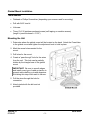
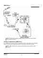
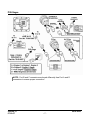
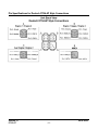
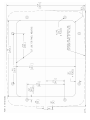
PowerView™
Model PV1000
Hardware Installation Manual
00-02-0599
07-19-07
Section 78
In order to consistently bring you the highest quality, full featured products, we reserve the right to change our
specifications and designs at any time. The latest version of this manual can be found at www.fwmurphy.com.
Warranty - A limited warranty on materials and workmanship for one year is given with this FW Murphy product.
A copy of the warranty may be viewed or printed by going to www.fwmurphy.com/support/warranty.htm
Please read the following information before installing.
BEFORE BEGINNING INSTALLATION OF THIS MURPHY
PRODUCT:
•
Read and follow all installation instructions.
•
Disconnect all electrical power to the machine.
•
Make sure the machine cannot operate during installation.
•
Follow all safety warnings of the machine manufacturer.
•
Please contact FW MURPHY immediately if you have any
questions.
Table of Contents
Product Information................................................................................................................ 1
Inspecting Package Contents.......................................................................................1
Hardware Installation.............................................................................................................. 2
Dash-Mounted Installation............................................................................................2
Gimbal Mount Installation.............................................................................................3
Wiring Instructions ................................................................................................................. 4
Single Engine ...............................................................................................................4
Dual Engine Static Addressing.....................................................................................5
NMEA Wiring................................................................................................................6
PVA Gages ..................................................................................................................7
Pin Specifications for Deutsch DT04-6P Style Connections.........................................8
Wiring Schematic .........................................................................................................9
Specifications........................................................................................................................ 10
(THIS PAGE INTENTIONALLY LEFT BLANK)
Product Information
The PowerView™ display is designed for instrumentation on electronically controlled engines
communicating using the SAE J1939 Controller Area Network (CAN), NMEA 2000 (GPS
features) or a proprietary blend of protocols. The PowerView display is a multifunction tool that
enables operators to view many different engine, equipment, or transmission parameters and
service codes, and can support many devices simultaneously.
Two mounting options are provided for the display. The in-dash mounting option requires a
hole to be cut for insertion of the display. A plastic installation template P/N 78000386 is
included in the box and a drawing is also provided in the back of this document.
The gimbal-mount method enables the display to be installed on a flat surface. Its design
allows you to rotate and tilt the unit for the best display position for the operator’s viewing.
NOTE: Please read the PV1000 Operations Manual for detailed instruction on
the use and operation of the display.
Inspecting Package Contents
Before attempting to install the product, it is recommended that you ensure all parts are
accounted for and inspect each item for damage (which sometimes occurs during shipping).
The items included in the box are:
•
PV1000 unit
•
front cover snap on – P/N 78-05-0302
•
installation kit – P/N 78-00-0386 includes:
•
8 mounting screws and nuts
•
extra SD card cover
•
back plate (can be used as mounting template)
•
Installation manual
•
Operations manual
Section 78
07-19-07
00-02-0599
-1-
Hardware Installation
The following instructions will guide you through installing the PowerView display.
Dash-Mounted Installation
Tools needed.
•
Drill with 9/64” size bit
•
Jig Saw
•
Wrench or socket for #6 Keps locking nuts (provided) to studs
Preparing the Dash
Determine the location of the PowerView in the dash. Use the Installation Template (included
in the box) as a guideline to cut a hole in the dash to the specified dimensions. Drill holes
where indicated on the template for the mounting screws.
NOTE: Use the plastic template included in the box whenever possible.
If you must use the paper template from the manual and you downloaded this
document from the FW Murphy website, be aware that the pdf file may not
automatically print to scale. When submitting the file for print, you will need to
select “None” for Page Scaling. Check the accuracy of the printed template by
verifying the measurements labeled on the template are correct.
If this manual was supplied with your product, the template will be correct.
Mounting the Unit
1. Attach the eight threaded studs to the back of the PowerView case.
2. Place the back side of the display through the opening in the dash.
3. Use the studs to line up the unit with the drilled holes.
4. Push the unit through the opening and studs through the drilled holes until the back of
the case is flush.
5. Use the #6 Keps locking nuts provided to tighten unit to the dash. Use the appropriate
wrench or socket to tighten. Torque lock nuts to 8-10 inch pounds.
Section 78
07-19-07
00-02-0599
-2-
Gimbal Mount Installation
Tools Needed
•
Flathead or Phillips Screwdriver (depending upon screws used for mounting)
•
Drill with 9/64” size bit
•
Hole saw
•
Three (3) 6-32 stainless panhead screws (self tapping or machine screws)
(length = panel thickness + 0.125”)
Mounting the Unit
1. Determine where the gimbal mount will be located on the dash. Attach the PowerView
to the gimbal mount and tighten the adjustment knob to hold in place.
2. Mark the screw holes needed for the
mount.
3. Drill holes for the mount.
4. Create a “pass-through” hole for the wires
from the unit. This hole can be partially
hidden by the triangle base of the gimbal
mount
IMPORTANT! Be sure to smooth edges
and install some type of cable protection to
prevent cable chaffing, cuts and abrasions.
Not taking this step could result in failures.
5. Pull the wires through the hole for
connection.
6. Attach gimbal with the bolt and nut
provided.
Section 78
07-19-07
00-02-0599
-3-
Wiring Instructions
The following illustrations are examples of various typical quick-connect options for 1 or 2
engine setups and gages. Wiring harnesses are sold separately.
Single Engine
Software Configuration for Single Engine Setup
To set the software configuration for single engine, on the System Settings screen, under
Wiring Configuration, select Engine(s) – Single Harness to Plug A – Engine 1, Engine 2.
Section 78
07-19-07
00-02-0599
-4-
Dual Engine Static Addressing
NOTE: Port A and B have different connector keys to ensure proper connection.
All cables are black with the exception of cables for Port B, which are yellow.
Software Configuration for Dual Engine Static Addressing
To set the software configuration for dual engine static addressing, on the System Settings
screen, under Wiring Configuration, select Engine(s) – Dual Harness to Plug A & B –
Engine1, Engine 2.
Section 78
07-19-07
00-02-0599
-5-
NMEA Wiring
NOTE: The NMEA wire harness contains blocking pins that only allow the cable
to be connected to Plug D.
Software Configuration for NMEA Setup
If only NMEA devices such as GPS are connected to Plug D, and engines are connected to
Plug A or B, then use the appropriate single or dual engine configuration settings.
NOTE: NMEA can be used in conjunction with all other engine options listed in
this manual.
Section 78
07-19-07
00-02-0599
-6-
PVA Gages
NOTE: Port B and C connectors are keyed differently than Port A and D
connectors to ensure proper connection.
Section 78
07-19-07
00-02-0599
-7-
Pin Specifications for Deutsch DT04-6P Style Connections
Section 78
07-19-07
00-02-0599
-8-
Wiring Schematic
Section 78
07-19-07
00-02-0599
-9-
Specifications
Electrical
Display
Resolution
Orientation
Backlighting
Processor
Flash Memory
RAM
EEPROM
Operating Voltage
Power Consumption
CAN
RS-485
Protocols
Connection
Keyboard
6.4” Color transmissive TFT LCD
VGA, 640 x 480 pixels
Landscape
CCFL, 350 cd/m² (50,000 h lifetime) not replaceable
Sharp ARM9 LH7A404, 200 MHz
Philips ARM7 LPC2194 70 MHz
16 Mbytes
32 Mbytes SDRAM
32 Kbytes
6 to 32 VDC, protected against
reverse polarity and load-dump
10 W full backlight
22 W full backlight with heater (< -10º C)
4 CAN ports according to CAN specification 2.0B.
One port isolated according to NMEA 2000
2 MODBUS Master ports at 38.4 Kbaud
J1939, NMEA 2000, proprietary
4 Deutsch DT04-6P 6-pin connectors
8 Capacitive Touch Keys
Mechanical
Mounting Variants
Dimensions
Cutout for panel mounting
Case Material
Weight
Section 78
07-19-07
Panel Mounting – Mounts with eight screws into the lip of the bezel.
Gimbal Mounting – Uses an articulating gimbal.
(W x H) 8.74 x 7.23 in
Panel Mount Depth – 0.605 in
Unit Depth – 3.265 in
(W x H) 7.15 x 5.65 in
High impact acrylic front case
Polycarbonate back case
2 lb
00-02-0599
- 10 -
Environmental
Operating Temperature
Storage Temperature
Protection
Emissions
Immunity
Section 78
07-19-07
-40º C to +85º C
-40º C to +85º C
IP68
IEC 60945, 95/54/EC
SAE J1113, ISO 11452
00-02-0599
- 11 -
MURPHY, the Murphy logo, PV1000 and PowerView are registered and/or common law trademarks of Murphy
Industries, Inc. This document, including textual matter and illustrations, is copyright protected by Murphy
Industries, Inc., with all rights reserved. (c) 2006 Murphy Industries, Inc. Other third party product or trade names
referenced herein are the property of their respective owners and are used for identification purposes only.