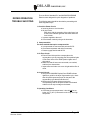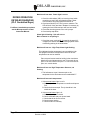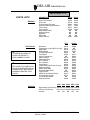
1
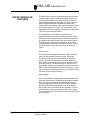
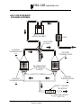
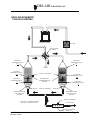
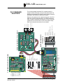
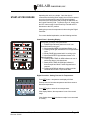
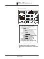
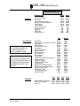
DRI-AIR INDUSTRIES, INC.
ARID-X & HP4-X 18-100
FLOOR MOUNT DRYERS
OPERATING MANUAL
OPERATING MANUAL - ARID-X, HP4-X 18-100 FM DRYERS
Revision 10/8/02
Page 1
DRI-AIR INDUSTRIES, INC.
DRI-AIR INDUSTRIES, INC.
16 THOMPSON ROAD
P.O. BOX 1020
EAST WINDSOR, CT 06088-1020
Tel. (860) 627-5110
FAX (860) 623-4477
Internet http://www.dri-air.com
e-mail: [email protected]
Page 2
OPERATING MANUAL - ARID-X , HP4-X 18-100 FM DRYERS
Revision 10/8/02
DRI-AIR INDUSTRIES, INC.
CONTENTS
DRYER OPERATION/FEATURES --------------------------- 4
AIR FLOW SCHEMATIC FOR ARID-X DRYERS -------- 6
AIR FLOW SCHEMATIC FOR HP4-X DRYERS --------- 7
DRYER CYCLE DIAGRAM ------------------------------------ 8
PLC STANDARD ELECTRICS ------------------------------- 9
INSTALLATION PROCEDURE ----------------------------- 10
Electrical Connection ------------------------------------- 10
Check for correct motor rotation ----------------------- 10
START-UP PROCEDURE ----------------------------------Standard Electrics ----------------------------------------To Set Temperature: -------------------------------------Microprocessor Control ----------------------------------
11
11
11
12
DRYER OPERATION-TROUBLE SHOOTING --------- 13
DRYER OPERATION-DETAILED DIAGNOSIS -------- 14
DRI-AIR ROTARY ZONE VALVE --------------------------- 15
PARTS LISTS
ARID-X & HP4-X 18 - 35 -------------------------------- 16
ARID-X & HP4-X 50 - 100 ------------------------------ 17
OPERATING MANUAL - ARID-X, HP4-X 18-100 FM DRYERS
Revision 10/8/02
Page 3
DRI-AIR INDUSTRIES, INC.
DRYER OPERATION/
FEATURES
The ARID-X dryer series is a dual bed design that provides a
constant supply of dry air to the material hopper. While one
bed is removing moisture from the process air the other is
regenerating by heating the desiccant to a high temperature.
Once the regenerated bed cools down, the Zone Valve
switches the airflow, and the newly regenerated bed is used to
desiccate the process air stream. The saturated bed is now
regenerated in the same manner, completing the regeneration
cycle. The cycle is depicted Page 8.
The airflow design of the ARID-X dryers makes the
regeneration cycle more efficient because we utilize a small
amount of the desiccated process air rather than ambient air
to regenerate the desiccant bed. This reduces the impact of
the high moisture content of the ambient air, which would
contaminate the desiccant bed, and allows the dryer to attain
a lower dew point. Please see the Air Flow Schematic on
Page 6.
HP4-X Design
Our patented HP4-X design incorporates 4 desiccant beds
where two are stacked, one over the other. This nearly
doubles the amount of desiccant available for drying the
process air stream, and because of the tower design, the
dryer is able to regenerate the desiccant in the same time as
our ARID-X series. This allows the dryer to operate in very
high humidity conditions without affecting the process air dew
point. In fact, this design produces dew point levels of – 40’ to
-80’ C for faster more complete drying of your material. Please
see the Air FLow Diagram on Page 7.
Hopper Design
Dri-Air’s ”all stainless” hopper design utilizes a stainless steel
inner shell surrounded by a stainless steel jacketed insulation
layer. The easily removable stainless steel spreader cone
promotes proper material flow to ensure that the material is
dried efficiently and no dried material is left at the hopper
bottom that needs to be fed out prior to operating. You must
ensure that your hopper is adequately sized for your usage
rate and is kept filled, to ensure that you have sufficient time to
dry the material.
Page 4
OPERATING MANUAL - ARID-X , HP4-X 18-100 FM DRYERS
Revision 10/8/02
DRI-AIR INDUSTRIES, INC.
DRYER OPERATION/
FEATURES (Cont.)
Dryer Controls
The ARID-X series can be supplied with the standard PLC
Control Module or the advanced Microprocessor Control
Module, while the HP4-X series is only available with the
Microprocessor Control Module.
The PLC Control module includes a PLC control board,
display board, temperature controller and touch pad that is
programmed for the drying cycle described above. The
controller, display board and touch pad indicate the machine
status, alarms, set points and allow you to enter operational
settings for the dryer. These are explained in more detail later
in this manual.
The Microprocessor Control Module is one of the most
sophisticated yet operator friendly controls on the market. It
has many more features than the PLC control module that
provide the operator with more control and operational
flexibility with the dryer. These features and the operating
instructions are covered in detail in the Microprocessor
Control Instruction Manual included with your dryer.
OPERATING MANUAL - ARID-X, HP4-X 18-100 FM DRYERS
Revision 10/8/02
Page 5
DRI-AIR INDUSTRIES, INC.
AIR FLOW SCHEMATIC
FOR ARID-X DRYERS
V O RT E X B LO W E R
FILT E R
4-W AY Z O N E
VA LV E
C O N TR O L
TH E R M O C O U PLE
H1
XX
C O N TR O L
TH E R M O C O U PLE
H2
VENT
R E G E N E R ATIO N
AND PROCESS
H E ATE R
S A FE TY TH ER M A L
C O N TR O L
TH E R M O C O U PLE
L1
C O N TR O L
TH E R M O C O U PLE
L2
S A FE TY TH ER M A L
TO H O P P E R
P R O C E S S H E AT E R
(A P D 5-9)
Page 6
OPERATING MANUAL - ARID-X , HP4-X 18-100 FM DRYERS
Revision 10/8/02
DRI-AIR INDUSTRIES, INC.
AIR FLOW SCHEMATIC
FOR HP4-X DRYERS
VO RTEX BLOW ER
F ILT E R
4 -W AY Z O N E
VA LV E
CONTROL
TH ER M O C O U P LE
H1
XX
CONTROL
TH ER M O C O U P LE
H2
VENT
CONTROL
TH ER M O C O U P LE *
M1
CONTROL
TH ER M O C O U P LE
L1
SAFETY THER M AL
SECONDARY
R E G E N E R AT IO N
H E AT E R
CONTROL
TH ER M O C O U P LE *
M2
CONTROL
TH ER M O C O U P LE
L2
SAFETY THER M AL
R E G E N E R AT IO N
AND PROCESS
H E AT E R
R E G E N E R AT IO N
AND PROCESS
H E AT E R
SAFETY THER M AL
* - CO NTRO L THERM O CO UPLE
F O R P L C C O N T R O L O N LY
TO H O P P E R
P R O C E S S H E AT E R
(H P D 5 -9 )
OPERATING MANUAL - ARID-X, HP4-X 18-100 FM DRYERS
Revision 10/8/02
Page 7
Page 8
Zo ne 2 C o o ling
Va lve Shifts
Va lve Shifts
Zo ne 1 C o o ling
DRYER CYCLE
DIAGRAM
Zo ne 2 He a ting
D rye r C ycle
D ia g ra m
D e sica nt B e d s
Zo ne 1 He a ting
DRI-AIR INDUSTRIES, INC.
XX
OPERATING MANUAL - ARID-X , HP4-X 18-100 FM DRYERS
Revision 10/8/02
UNUSED
L1
L2
M1
M2
H1
+
+
-
+
-
+
-
+
-
+
-
+
-
Tb1
C h0
C h1
C h2
C h3
C h4
C h5
OPERATING MANUAL - ARID-X, HP4-X 18-100 FM DRYERS
Revision 10/8/02
Jp3
7
6
Jp2
5
4
Jp1
3
Page 9
L2
R7
R6
R5
R4
C2
Jp5
Jp6
+ C18
C17
C12
R37
D0
D1
Rn6
D2
C7
C6
C5
C4
D3
D4
C8
U3
D5
C15
D15
U6
D7
C9
C13
U N U SED
D6
INPUTS
U4
J2
PO WER
U N U SED
Smal l PLC03 REV E
L1 Br1+
Jp4
U2
C2
U8
D14
D13
D12
D11
D10
D9
D8
C18
C19
J5
C14
DRI-AIR INDUSTRIES
EXPANDER BD REV C
R3
U5
Tb2
J5
R2
R1
Rn4
U18
XX
Jp7
+
OSC2
OSC1
+
+
Jp7
Rn7
OSC3
14
50
M2
T1
AL2
UNUSED
-
-
-
-
-
SS2
SS1
SS5
SS4
SS3
+
+
+
+
+
Z1 BOTTOM HEATER
Z2 BOTTOM HEATER
PROCESS HEATER
ARID-X 50-100
Z2 TOP HEATER
Z1 TOP HEATER
14 ZONE VALVE
13 MAIN CONTACTOR/TEMP CONTROL
12 UNUSED
11 HIGH TEMP. ALARM (OPTIONAL)
10 ALARM (OPTIONAL)
9A UNUSED
9
110 VAC
FROM XFORMER
CR1
AL1
J11
UNUSED
J11A
8A UNUSED
8
MOTHER BOARD
P/N 84100
U7
U1
L2
L1
+
C 20
U9
QT9
+
S1
H.P ONLY 50-100 PROCESS TUBE
QT5 QT6 QT7 QT8
GROUND
JUMP
UNUSED
UNUSED
HI TEMP. ALARM SIGNAL
7 DAY TIMER
SAFETY
# 9 TEMP. CONT SIGNAL
R36
C 14
2
11
10
9
8
UNUSED
UNUSED
TC1
7 DAY TIMER
7
OL1
6
5
4
3
50-300
NON H.P.
PORT
DISPLAY BOARD - P/N 83401
D 16
2
TC1
JP3
1 2 3
DegC
X 10
J2
J1
ANALOG
TC
JP2
S2
1
0
C4
C9
OSC1
C5
C8
D 20
1
C3
U10
C11
C7
C6
JP1
C19
C21
R 14
R38
0
C2
U1
C1 UNUSED
C1
C10
C18
C20
Rgain
D 15
C1
PW R
C12
C13
C 14
C 15
C 16
C 17
H2
1 2 3
TC rev B
1 2
-
R 13
C 22
C 23
R 12
R8
D 12
Z1
C 15
C0
U2
Rn3
C 13
C1
D 10
C2
D 14
D 16 C 3
U9
Rn5
D9
C16
J2
D 13
O SC 3
R 11
D8
C 11
U 2A
U11
U5
J118
O SC 1
1
O SC 2
J12
1
R2
D 11
O UT PUTS
PLC STANDARD
ELECTRICS
Rn7
O SC 1
THERMOCOUPLE BOARD
DRI-AIR INDUSTRIES, INC.
The control package includes a PLC controller which is
programmed for the drying cycle previously discussed. The
display board indicates the machine status, heater operation
and alarms. See section on start up for details.
Below are descriptions of the inputs and outputs of the PLC
which are used for trouble shooting. A lit LED indicates the
input or output is actuated. All inputs are 12 volts AC and all
outputs are 110 volts AC and 15 v DC to the heater relays.
Refer to the electrical schematic for more detail.
C 11
H I TEM P
M AIN
SAFETY
TEM P
50-300
N O N H .P.
DRI-AIR INDUSTRIES, INC.
INSTALLATION
PROCEDURE
For all Dri-Air models except ARID-X 10, AHM-1, & PDII
Electrical Connection:
Open electrical access door on the front of the machine by
turning the disconnect off and turning the lower clamping
screw 1/2 turn counterclockwise. Locate the disconnect by
following the operating handle down to the electrical panel.
Insert the incoming power cable or conduit through the hole
provided on the side of the machine.
« use approved wire and fastening means «
Wire incoming power to the top of the disconnect as shown in
the diagrams below.
NOTE:
When 3 wire supplies are used in place of 4 wire supplies,
a control transformer is required.
XX
3 PHASE DRYER INSTALLATION
CHECK FOR CORRECT MOTOR ROTATION
BEFORE RUNNING DRYER
To check motor rotation.......
Leave the electrical cabinet door open so the blower can be
observed. Turn on the power to the dryer and press the ON/
START touch pad and then immediately press the OFF/STOP
touch pad. Observe the cooling fan on the top of the blower
motor and verify the fan is turning clockwise. If the motor is
not turning clockwise, switch any two adjacent supply wires.
The unit is now ready for operation.
Page 10
OPERATING MANUAL - ARID-X , HP4-X 18-100 FM DRYERS
Revision 10/8/02
DRI-AIR INDUSTRIES, INC.
Standard Electrics
START-UP PROCEDURE
Operating this unit is very simple. Once the dryer is
connected to the facility power supply, the unit can be started
by turning the disconnect located on the electrical panel
enclosure to the ON position and pressing the ON button on
the Control Panel Key Pad. To shut the dryer off, simply push
the OFF button on the Control Panel Key Pad and turn the
disconnect to the OFF position.
Setting the process air temperature is done using the Digital
Controller.
For a more detailed explanation, see the following sections.
Control Panel - Operating Display
Turn power on to dryer using disconnect.
1. POWER light indicates power to the unit is on.
Press ON button on key pad.
XX
2. Illuminated BLOWER Light indicates Blower is on.
3. Flashing ZONE light indicates bed is in Regeneration
cycle.
4. Steady ZONE light means bed is in cooling cycle.
5. Illuminated HEATER light indicates heater is on.
Alarm Conditions:
6. Flashing HIGH TEMP. ALARM indicates an over or
under temp alarm. Unit shuts down.
7. Steady HIGH TEMP. ALARM light indicates a
thermocouple has failed. Further diagnostics are
required.
8. Flashing ALARM light indicates a safety override
condition has occured. Dryer shuts down.
Digital Controller - Setting Process Air Temperature:
Press SET button - temperature set display will flash.
Press up arrow to increase temperature and down arrow to
decrease temperature.
Press SET again to enter the new temperature.
If the display flashes, the temperature is out of the control
range.
If the display shows 0000 the thermocouple is not connected
or is faulty.
OPERATING MANUAL - ARID-X, HP4-X 18-100 FM DRYERS
Revision 10/8/02
Page 11
DRI-AIR INDUSTRIES, INC.
Microprocessor Control
1.
2.
3.
4.
Power light indicates there is power on.
After initializing, dri Air will be displayed.
Press START to start the dryer.
To set the temperature:
press SET - right display shows set temp
change setting using arrow keys
press ENTER to input new setting
5. Left display indicates actual temperature
6. Right display shows dewpoint or set temp
press TEMP D.POINT button to change
7. To set high temp alarm: (degrees over setting)
press ALARM - right display shows setting
change setting using arrow keys
press ENTER to input new setting
8. Status block indicates heater on or fault
9. See manual for setting 7-day timer .
10. Configuration of the dryer parameters is done
using the setup button. see manual.
For a more detailed explanation of the features and operation
of the Microprocessor Controller, please consult the
Microprocessor Control Operating manual enclosed with this
unit.
Page 12
OPERATING MANUAL - ARID-X , HP4-X 18-100 FM DRYERS
Revision 10/8/02
DRI-AIR INDUSTRIES, INC.
DRYER OPERATION
TROUBLE SHOOTING
The new Dri-Air Standard PLC and MICROPROCESSOR
Electrics were designed for quick diagnosis of problems.
The following steps should be done before proceeding with
other diagnostic steps.
1. Check the Power Circuit:
a. Incoming fuses or circuit breaker
b. All dryer fuses:
Each fuse, with the exception of the main fuses, has
a blown fuse indicator light that illuminates when the
fuse is blown.
c. Is power supplied to the unit?
d. Check heater continuity using a volt ohmmeter.
2. Compressed Air:
For those models that require compressed air.
a. Is compressed air connected with at least 60 PSI
b. Check water separator and drain if necessary
c. Pressure gage should read 60 PSI
3. Air Flow Circuit:
a. Ensure Zone Valve position corresponds to the
regeneration cycle by comparing the Zone position lights
on the Zone Valve to the ZONE position lights on the
dryer panel.
b. Make sure that all hoses are connected, not crushed,
and free from obstructions.
c. Inspect filter and make sure cover is tight and the filter is
clean.
4. Control Circuit:
a. Using the PLC/MICRO Display Panel ZONE indicator
lights as a guide for the dryer regeneration cycle, check
that all inputs/outputs are proper for the part of the
regeneration cycle that the machine is in.
b. Monitor the PLC output lights to ensure the
corresponding LED on the power board is illuminated
and there is an output voltage to the heater.
5. Operating Conditions:
a. Check the process temperature. It should not be set
below 140° F (60° C) because the unit will go into high
temp alarm.
OPERATING MANUAL - ARID-X, HP4-X 18-100 FM DRYERS
Revision 10/8/02
Page 13
DRI-AIR INDUSTRIES, INC.
Machine will not start: Power light is not on.
DRYER OPERATION
DETAILED DIAGNOSIS
(PLC Controlled Dryer)
For Micro Controlled dryers please
see the Microprocessor Control
Instruction Manual
1. Check circuit breakers (CB1) or incoming fuses inside
control box to see if they are tripped or blown. Reset
circuit breakers by turning them off and then on.
2. Check small fuses (FU1 & FU2) next to contactor. The
LED will be lit if they are blown. Replace if necessary by
opening the fuse holder and put new fuse into holder.
3. Check that incoming power to the unit is proper.
4. Check safety snap discs.
Alarm light is flashing: Unit will not run.
Main contactor is not pulling in.
1. Check the motor overload OL1 located in the panel. If it
is tripped, the window will show as orange/yellow. Reset
overload by pushing in the reset button.
Machine will not run: High Temp Alarm Light flashing:
This indicates that the temperature has exceeded the high
limit programmed into the temperature control or the set
temperature can not be reached.
Press stop and restart machine holding in the start button.
Monitor the actual temperature to see if it exceeds the set
point or can not reach the set point. If it can not reach set
point, see section below.
Machine will not run. High Temperature Alarm on, not
flashing:
1. This indicates an “open” thermocouple or the
temperature in the desiccant tower exceeded 900° F.
Machine will not reach temperature:
1. If the process heater light is not lit.
A. Check output from temperature controller and input to
PLC.
B. Check the thermocouple. The tip should be in the
middle of the hose.
2. If the process heater light is lit.
A. Check fuses on power board
B. Check solid state relays on power board.
C. Check that the air flow is correct.
D. Check blower rotation
E. Check heater for continuity.
Page 14
OPERATING MANUAL - ARID-X , HP4-X 18-100 FM DRYERS
Revision 10/8/02
DRI-AIR INDUSTRIES, INC.
Check the limit first by pressing the SET button on the
temperature control and holding until AL is displayed. The
setting shown indicated the amount over set point that the
alarm will be actuated. It is factory set to 50°F (30°C) and
should not be set below 30°F (16°C) or it will actuate too soon.
If the temp exceeds the set point check the following:
1. Remove the hose from the top of the hopper to check air
flow. There should be air flow out of the hopper with a
suction on the hose. If there is little or no flow, check the
inlet hose.
2. Inspect the filter to make sure that it is clean and not
affecting the air flow.
3. Check the power boards to see if one of the solid state
relays has failed on. Using an ammeter or voltmeter on
the output to the heater, see if there is power when the
LED is not lit which will indicate a failed relay.
4. Check the valve position.
DRI-AIR
ROTARY ZONE VALVE
The Dri-Air rotary valve is designed to provide very little flow
restriction and no leakage. It incorporates high temperature,
self adjusting seals for years of trouble free service. The
electrical controls are built into the end of the valve and
include position lights.
Trouble shooting is easy. If the lights indicating position do not
match the zone displayed on the control panel, or there are no
lights, the valve is not working properly. See if the cam is
actuating a switch.
DO NOT PUT FINGERS INTO VALVE WITH POWER ON
Check all electrical connections to make sure they are tight.
Contact factory with the serial number of the dryer for a
replacement valve.
OPERATING MANUAL - ARID-X, HP4-X 18-100 FM DRYERS
Revision 10/8/02
Page 15
DRI-AIR INDUSTRIES, INC.
ARID-X & HP4-X 18 - 35
PARTS LISTS
GENERAL
ELECTRICAL
NOTE:
TO ORDER BLOWERS OR
OVERLOAD REFER TO
PART NUMBER ON ITEM.
*:
IEC CONTACTOR USED IN ALL
FM, PD & HM DRYERS AND CLL
POWER PACKS WITH SERIAL
NUMBERS GREATER THAN
D14650
DESCRIPTION
Arid-X
HP4-X
Dryer Filter Element
Zone Valve
Thermocouple (Process)
Desiccant 80082 (Lbs/Machine)
Tower Clamp
Tower Gasket
Regeneration Valve
Pressure Switch
Regulator
MAC Valve
Caster (Swivel)
81055
83705
84054
8 lbs.
81017
81028
NR
NR
NR
NR
80981
81055
83705
84054
14 lbs.
80017
81028
NR
NR
NR
NR
80981
Disconnect
Temperature Control (RKC CB-100)
Main Board
Display Board
Thermocouple Board
Transformer
Current Transformer
Main Contactor
Solid State Relay
IEC Contactor
IEC Contactor*
Power Board
Power Board (208 & 230 v Dryers)
Single Pole Relay
Double Pole Relay
Dual Solid State Board
Toggle Switch
Safety Thermal Switch(Tower)
Thermocouple (Tower)
TRI-Solid State Board
Dewpoint Sensor
STD
MICRO
82308
84016
84100
83401
84049
83437
NR
82270
82302
80576
84860
83493
84080
82496
80587
NR
80466
80221
82174
NR
81908
82308
NR
82071
82072
NR
84131
82246
82270
82302
80576
84860
83493
84080
82496
80587
82870
80466
80221
82174
83468
81908
208V 230V 400V 480V 575V
HEATERS
Regeneration (Cone Style) 83342 83373 83982 83374 84235
HP Center (Flat Style)
82373 82373 83958 82505 84260
Process
NR
NR
NR
NR
NR
Page 16
OPERATING MANUAL - ARID-X , HP4-X 18-100 FM DRYERS
Revision 10/8/02
DRI-AIR INDUSTRIES, INC.
ARID-X & HP4-X 50 - 100
GENERAL
ELECTRICAL
NOTE:
TO ORDER BLOWERS OR
OVERLOAD REFER TO
PART NUMBER ON ITEM.
*:
IEC CONTACTOR USED IN ALL
FM, PD & HM DRYERS AND CLL
POWER PACKS WITH SERIAL
NUMBERS GREATER THAN
D14650
DESCRIPTION
Arid-X
HP4-X
Dryer Filter Element
Zone Valve
Thermocouple (Process)
Desiccant (Pounds / Machine)
Tower Clamp
Tower Gasket
Regeneration Valve
Pressure Switch
Regulator
MAC Valve
Caster (Swivel)
81331
83705
84054
30 lbs.
81172
82795
NR
NR
NR
NR
80981
81331
83705
84054
50 lbs.
81172
82795
NR
NR
NR
NR
80981
Disconnect
Temperature Control (RKC CB-100)
Main Board
Display Board
Thermocouple Board
Transformer
Current Transformer
Main Contactor
Solid State Relay
IEC Contactor
IEC Contactor*
Power Board
Power Board (208 & 230 v Dryers)
Single Pole Relay
Double Pole Relay
Dual Solid State Board
Toggle Switch
Safety Thermal Switch(Tower)
Safety Thermal Switch(Process)
Thermocouple (Tower)
Transformer .050
TRI-Solid State Board
Dewpoint Sensor
230V
STD
MICRO
82308
84016
84100
83401
84049
83437
NR
82270
82302
80576
84860
83493
84080
82496
80587
NR
80466
80221
80551
82175
82245
NR
81908
82308
NR
82071
82072
NR
84131
82246
82270
82302
80576
84860
83493
84080
82496
80587
82870
80466
80221
80551
82175
82245
83468
81908
400V
480V
575V
HEATERS
Regeneration (Cone Style)
HP Center (Flat Style)
Process
OPERATING MANUAL - ARID-X, HP4-X 18-100 FM DRYERS
Revision 10/8/02
81351 81766 81366 81432
82364 83934 82493 83372
82343 84204 82319 84065
Page 17
DRI-AIR INDUSTRIES, INC.
NOTES:
Page 18
OPERATING MANUAL - ARID-X , HP4-X 18-100 FM DRYERS
Revision 10/8/02
DRI-AIR INDUSTRIES, INC.
NOTES:
OPERATING MANUAL - ARID-X, HP4-X 18-100 FM DRYERS
Revision 10/8/02
Page 19
DRI-AIR INDUSTRIES, INC.
NOTES:
Page 20
OPERATING MANUAL - ARID-X , HP4-X 18-100 FM DRYERS
Revision 10/8/02