1
EMA
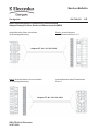
Alkatrészlista
Tűzhely, főzőlap
2250
PNC
949592498
ELC
00
Márkanév
AEG Electrolux
Modell
78001KF-MN 69F
Piac
BE - CZ - DE - EE ES - FI - LT - LV NL - PT - RU - UA
Elektromos,
indukciós
Distriparts Deutschland GmbH
Muggenhofer Straße 135
D-90429 Nürnberg
Germany
Fax +49 (0)911 323 1022
© Electrolux
Publikáció szám
599524631
2009/10/28
DGT
NDGTMG4029
© Electrolux
- 1 -
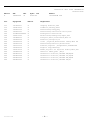
Mátrix
A
PNC
949592498
Poz.
Anyagszám
Mátrix
Megnevezés
001
012
093
094
096
098
099
306
999
999
999
999
999
999
999
999
999
999
3307266217
3305879201
3305623005
3305623021
973949592498001
3871870063
3304588001
3306596002
3305142006
3305623039
3305733010
3305934006
3306374012
3306485008
8229255230
8229255248
8229255255
8229255263
A
A
A
A
A
A
A
A
A
A
A
A
A
A
A
A
A
A
Üveglap kerettel,69F
Indukció,főzőlap,D210
Felszerelés,erőegység
Felszerelés,szellőztető motor,hűtő
Konfigurált elektronika
Elektronika,beadagolás,dupla,L+R
Talapzat,keret,elektronika,HIC UI
Burkolat,sorkapocs,G4
Cavar ,rögzítés,Elektronika fedél,4x14 PZ
Felszerelés,hálózati,elektronika
Tömítés,ragasztó ,üvegkerámia,6x2x2900mm
Rögzítő rugó,munkalap
Kábel,kijelző- és kapcsoló modul,szûrõ,X67
Hálózati kábel,gumi ,4x2,5
Használati utasítás,78001KF DE,EN,EL
Használati utasítás,78001KF SV,FI,RU
Használati utasítás,78001KF FR,PT,ES
Használati utasítás,78001KF DA,NO
© Electrolux
ELC
00
Robbantott ábra szám: NDGTMG4029
N00002079216
Modell
78001KF-MN 69F
Gyárt. Idő
20051219
- 2 -
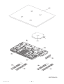
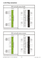
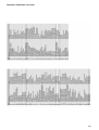
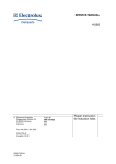
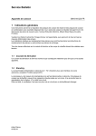
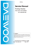
Operative Equipment Overview
© Electrolux
- 3 -
EN
THE ITEM(s) SHOWN IN
THIS DRAWING MUST
NOT CONTAIN
FORMALDEHYDE,
CADMIUM, MERCURY,
ASBESTOS ORPBB/PBDO.
9
X1/
1
X1/
2
X1/
3
D
SAFETY RISKS
!
5
4
3
2
1
Induktionsmodul
induction module
X2
3pol
X1
X12
1
Bedienplatine rechts
user interface right
X14
Filterplatine
filter board
2
3
4
X9
X10
3
1
X13
1
2
3
4
X8
X7
1
3
X11
1
X4
X5
PE
X17
2
D
10pol
1
2
3
4
3
1
X10
X2
X1
Leistungsplatine / power board
links / left
1
: VISIBLE SURFACES
DRAFT ANGLES (NOT SHOWN): 00°00'00"
[2] CRITICAL DIMENSIONS WHICH
MUST BE UNDER CAPABILITY
6
E
X7
C
7
N2
THIS DRAWING CONTAINS CONFIDENTIAL INFORMATIONS.
IT'S PROPERTY OF ELECTROLUX WITHOUT WHOSE
PERMISSION IT MAY NOT BE COPIED, SHOWN OR HANDED
TO A THIRD PARTY OR OTHERWISE USED, AND IT IS TO
BE RETURNED PROMPTLY UPON REQUEST TO ELECTROLUX
WHICH IS RESPONIBLE FOR THE DRAWING.
E
8
X9
1
2
3
X8
X6
1
3
X10
X1
X2
Leistungsplatine / power board
rechts / right
2
X4
4
4
X5
X6
X8
M
3
X5
X9
X7
Bedienplatine links
user interface left
X4
C
Spulenträger / coil carrier
R
X1/
L
R
L
R
L
R
L
see respective wiring
diagram hob cpl.
siehe entprechenden
Verdrahtungsplan Mulde
komplett
4
X1/ 5
B
B
PE
-
DEVELOPED FLAT AREA
-
THEORETICAL FLAT AREA
X1/
Lüfter
fan
Leistungsplatine
power board
Filterplatine
filter board
Leistungsplatine
power board
A
first edition
Weiß
links
left
LENGTHS AND DIAMETERS:
<18 mm.
: ±--18 - 80 mm. : ±-->80 mm.
: ±---
: ±--*
ANGLES
A
GENERAL TOLERANCES
ZUST
2
3
rechts
right
DESIGN
MODIFICATIONS
OWNER
DATE
CHD
DGR-PE_PD
4
TITLE
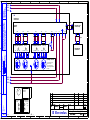
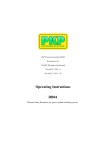
circuit diagram induction G4 (split)
Schaltplan Induktion G4 (split)
7
EUROPEAN
METHOD
2005-03-21
APPR
Weiß
- 4 8
DATE
USERS
NUMBER
9
2005-03-21
REQUEST
DESIGN
TITEL
©A4 Electrolux
DGT 26149
Weiß
DGT
1
DRN
SIGNATURE
6
5
4
3
387 0608
2
SHEET
REV
01(01)
1
A
A
SERVICE MANUAL
HOBS
© Electrolux Distriparts
Muggenhofer Straße 135
D-90429 Nürnberg
Germany
Fax +49 (0)911 323 1022
DGS-TDS-N
Ausgabe: 04.08
DGS-TDS-N
21.04.08
Publ.-Nr.
599 519 523
685
EN
Repair-Instruction
for induction hobs
2
599 519 523 EN
1 General Information
These instructions serve the repairing of autarkic cooking hobs and cooking hobs in combination with
an oven with 3 or 4 inductions cooking zones respectively of the type E.G.O.. Also includes hobs with
2 induction zones (Domino, Mixed, Mixed gas) and the Frontline appliance series.
Please search for the corresponding alarm
symptom and then go through the alarm remedy measures from top to bottom.
Information concerning the replacement of parts is to be found in the corresponding replacement
instructions or are included with the spare parts.
All work is only to be carried out on the induction modules and the heating elements are only to be
carried out after they have been disconnected.
1.1
Leak current
A leak current of 5mA is normal and is therefore much higher than with other appliances.
1.2
Standby
The Standby power consumption amounts to < 1W (Induction plus user interface in the autonomous,
exception Frontline up to 2W).
The µprocessor for the measuring of the coil temperature is deactivated in standby, i.e. should the
cooking hob be heated up to hot pan being on the zone, no heating display "H“ is displayed when
switched off.
In this condition, the ventilator is also not switched on by external heating.
DGS-TDS
21.04.08
3
1.3
599 519 523 EN
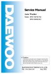
Block Diagram/Hob elements
Coils incl. Temperature
sensors.
Touch control w. carrier
Cover plate
Coil carrier
Cooling fan
Induction module w.
plastic housing incl.
mains terminal
Filter pcb
Power mod. Left
PowerMod. Right
DGS-TDS
21.04.08
4
599 519 523 EN
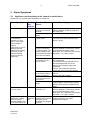
2 Alarm Symptoms
2.1
Appliance not functioning at all, cannot be switched on
References e.g. (1) refer to the illustrations in Chapter 2.8
Alarm Symptom
Cooking Possible Alarm
Hob
Cause
Display
Alarm Remedying
House fuse triggered
None
(1) Test the pin assignment and
230VAC between N and the phases on
the supply line.
See chapter 3 Testing Power Component
Cooking field cannot
be switched on.
Normally no "pips"
approx. 4 sec. after
mains voltage is
applied
respectively no quick
flashing up of the
display in the cooking
zone with not selfsufficient cooking
zones or front line
appliances.
None
Incorrect connection at
the power connection
terminal.
Final induction phase
defect.
Electronic system no
longer reacts
No mains voltage or
incorrect connection
(1 phase missing ->no
control voltage; N not
connected to terminal 4
and 5 not connected)
(1) Test the pin assignment and
230VAC between 4 N and the 2 phases
on supply line terminals 1 and 2.
Both of the "N“s should be connected to
terminals 4 + 5, if appr. jumper.
Disconnect the appliance from the mains
using the house fuse, reactivate after
approx. 10 sec..
No 5VDC betw. Pin 1 +
3 of the Bus for the
Touch Control
(2) Test 1+3 5VDC on the underside of
the cooking field
(corresponds with the external lines of
the bus between filter and Touch
Control), if not applied, replace the
Filterboard.
Caution: this is difficult to test from
underneath using normal test probes!
Connector of the cable (3) Test connector at the filter and Touch
to the Touch Control /
Control.
Display not inserted.
Reapply the mains voltage.
Fuse strip conductor burnt See chapter 3 "Check power section'"
out and/or final induction
phase defect
Touch control/display
defect.
Every 5-10 sec "beep"
of touch control
None
Only Frontline
All
appliances: cooking
indications
zone can not be
ON
activated. Display fully
on for more than 5 sec.
DGS-TDS
21.04.08
N not connected to
terminal 4 or 5.
Flat band cable
between user interface
and glass (touch
keyboard) not plugged
correctly.
If 5VDC exist and power component already
replaced: replace Touch Control, ensure
that the Touch Control is applied to the
glass.
(1) Test the pin assignment and
230VAC between 4 N and the 2 phases
on supply line terminals 1 and 2.
Both of the "N“s should be connected to
terminals 4 + 5, if appr. jumper.
Check line for seat and correct position
(contact direction), see capter
"References Frontline"
5
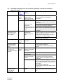
2.2
599 519 523 EN
Individual cooking zones do not work (partially) or work incorrectly or
cannot be used
Alarm Symptom Cooking Possible Alarm
Hob
Cause
Display
Alarm Remedying
Pan does not heat
up.
Pan in the border
area of the pan
detection and only
works with low power
Pan not detected.
Use different pot or this pot on a smaller
hob. See Chapter 4 Pot Detection
Information
Touch Control defect.
1) See Chapter 5. Touch Control Autarkic
Cooking Hobs Information..
2) Should this not help, replace Touch
Control.
(4) Change installation situation.
Normal
cooking
phase
Flashing
"F“
Display "F" with 2
hobs with all pots
(also 1 hob with 3
hob models)
Flashing
"F“
No power on all hobs Normal
cooking
phase
Individual buttons
cannot be used or
cannot always be
used.
Cooking hob power
Normal
too low or not
cooking
provided for a longer phase
duration.
Check whether the pots or pans are
suitable for induction. See 4 Pot Detection
Information
Coil not correctly
Check whether the coil lines are connected
connected.
and the torque has been adhered to.
Distance between coil Check whether the coil is applied to the
and glass ceramic too glass ceramic and whether the glass was
large.
pushed was pushed down when screwing
in position.
1 phase missing ; only (1) Test the pin assignment and
possible with
230VAC between 4 N and the 2 phases on
induction SW.Ver.
supply line terminals 1 and 2.
0.50.
Both of the "N“s should be connected to
terminals 4 + 5, if appr. jumper.
Should the above not succeed, replace the
affected power component..
Demo mode
See Chapter 5.2
activated.
Incorrectly installed,
exhaust not possible
to the front.
Unsuitable pots
(bottom bent)
Induction coil is not
applied to the glass
ceramic
Fan does not start.
"H" in display when
cooking hob and
oven cold and
switched off.
DGS-TDS
21.04.08
"H“
Temperature sensor
defect.
See Chapter 4 Pot Detection Information
Check whether the glass ceramic was
pushed down when being screwed in
position and the coil has been correctly
positioned.
1) When setting a cooking phase >0, the
fan runs at a slow speed. If not, check the
fan for foreign bodies, remove these where
appropriate.
2) If necessary, replace fan.
3) Should this not succeed, replace power
component.
Replace corresponding coil with
temperature sensor. Also see Instructions
"E4“.
6
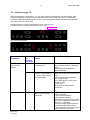
2.3
599 519 523 EN
Alarm message "E“
When the appliance is switched on, "E“ / „xx“ Alarm Number is displayed in the timer display. With
Frontline the display of the front zone indicates the error number when switching on. The affected
zones are subsequently displayed with an "E" in the cooking phase display and are thereby disabled.
The other zones can still be used.
example (left touch control / right indication in the cooking zone):
1) Display alarm number after switching on for 10 sec.
Alarm number
E5
2) 2 zones are disabled.
0
E
Alarm
Symptom
E
0
Display in Possible Alarm
the
Cause
Cooking
Hob Timer
Alarm display in the "E0“
Touch Control
display.
Incorrect configuration on
the Filterboard.
"E3“
Under voltage or over
voltage, is only displayed
for 10 sec. after voltage
has been applied.
"E4“
Coil temperature sensor
defect or not correctly
connected.
DGS-TDS
21.04.08
Alarm Remedying
Disconnect cooking hob from mains,
wait 10 sec and reconnect the mains
supply.
Should alarm still be displayed,
replace filterboard..
1) Disconnect cooking hobs from the
mains, wait 10 sec. and reconnect the
mains.
2) Should alarm still be displayed,
test L1 against N (4),
test L2 against N (5) at the mains
connection (1).
3) If OK, see
See Chapter 3 Testing Power
Component
1) (5)Inspecting the contacts on the
power component.
Is the connector inserted?
2) The resistance at room
temperature (25°C) amounts to 1000
Ohm. This corresponds to approx. 3.3
Ohm per +1°C deviation.
If not in this range, replace affected
coil including temperature sensor.
3) Should above not succeed, replace
power component concerned.
7
Alarm
Symptom
Display
in the
Cooking
Field
Timer
Alarm display in the "E5“
Touch Control
"E6“
Possible Alarm
Causes
Alarm Remedying
1 phase missing
1) Check the house fuse.
2) Check the pin assignment, (1)
test L1 against N (4),
test L2 against N (5)
3) If ok, see Chapter 3.
1) (5)Checking of the contact with the power
element.
Is the temp. Sensor connector locked in place
or the dummy connector (3 zone appliances,
no coil connected) inserted?
2) The resistance at room temperature (25°C)
is 1000 Ohm.A deviation of +1°C
corresponds to approx. +3.3 Ohm
Replace the corresponding coil incl.
Temperature sensor if not in this zone.
Communication
interference
between filter and
power component.
or temp. Sensor is
defective/missing
"E7“
"E8“
"E9“
DGS-TDS
21.04.08
599 519 523 EN
Note: a norm
requirement with
regard to new
powerboards results
in the power supply
for the electronics
on the powerboard
being deactivated in
the case of a
missing or incorrect
temp. sensor value.
Alarm Temperature
sensor heat sink
power component
Communication
interference betw.
filter and Touch
Control.
Central line at
RAST2.5 connector
/ line defect.
Incorrect
configuration for the
Touch Control on
the Filter board.
1) Check the cables between the two boards.
(6), Reinsert connector.
Or replace cable.
2) Should all of the zones on the cooking hob
be affected (Display "E" in the cooking phase
display), replace filter board .
3) Should the above not succeed, replace
power component.
Replace affected power component.
1) (3) Inspect connector at filter and the
Touch Control. Replace cable or filter and
Touch Control.
Reconnect mains voltage.
2) Should above not succeed, replace Touch
Control.
3) Should above not succeed, replace Filter
board.
Disconnect cooking field from the mains. Wait
10 sec. and reconnect to the mains voltage.
Should alarm still be displayed, replace Filter
board.
8
2.4
Other alarm symptoms
Alarm
symptoms
Display
Buzzer defect
Individual display
elements do not
illuminate or do not
do so continuously.
Penetrating aromas
from the hob when
warm.
Pots cause noises
2.5
599 519 523 EN
Possible Alarm
Cause
Alarm Remedying
Touch control
defect.
Defective display
elements
Replace Touch Control.
Coils subjected to a
manufacturing
defect.
Unsuitable pots.
Normal sound level
The aroma is non-toxic. Replace the affected
coils. These also have a slight arom when
cold. Clean the glass and aluminium sheet.
See Chapter 4 Pot Detection Information.
Interference noises result from the high
working frequency of the induction. This can
vary from pan to pan.
When measured in operation pursuant to
EN60335 §11-3 pursuant to EN60704 with 4
pots <47dBA.
A pot with boiling water has approx. 6062dBA.
Replace Touch Control.
Cooking zone with electric heating element not functioningt
Alarm symptoms
Possible Alarm Cause Alarm Remedying
Cooking zone not
functioning.
No phase 2 power voltage
or wrong connection
Electric heating element
defect
Relay defective
If the above should not
succeed.
DGS-TDS
21.04.08
(1) Check the pin configuration and
230V AC between N (4) and the phases
at terminals 1 and 2.
(7) Check whether the electric heating
element is open between the connections
or whther it has short-circuited. Replace
the heating element if defective.
8) Check whether the rely is defective
and whether no voltage is applied to the
electric heating element. Also refer to the
circuit diagram.
Replace the filter module with the relay
9
599 519 523 EN
(1)
(7)
(8)
2.5.1 Electric heating element relay instructions
•
•
2.6
Refer to the wiring diagram xxx.
The electric heating element is pulsed on relay board HOC2000 in the cooker.
Phase commutation with the cooker/hob combination, refer to Chapter 2.6, special error
images for the cooker/hob combination.
Special error images for the cooker/hob combination
•
•
•
•
Peculiarities:
Output
L2 is not continuous and is only connected through when the right zone is switched through
(D37 / D39, Details, refer to the wiring diagram).
The display in the hob is supplied with 5V DC from the induction module.
The electronic hob control in the cooker is supplied with 5V DC from the HOC2000
powerboard in the cooker.
Mixed with the electric heating element:
with the cooker/hob combination, the phases are normally connected to the
L1
left cooking zone
L2
right cooking zone
The induction module (front left and right cooking zones) are however connected to the
continuous phase L1.
Therear right electric heating element zone is always connected to L2.
L2 is only available however of one of the right cooking zones is switched on.
In order to avoid an overloading of L1, the rear left zone is therefore operated with L1 (D29) or
L2 (D37) if the front right zone is switched on.
The phase commutation is executed with the assistance of relays K501 and K504
A safety conductor strip (9) conductor strip of the K501 which can trigger a relay in case of an
error occurring (e.g. contact stuck together).
The output of the 210mm induction cooking zone is set to "P" if none of the right zones are
switched on and the rear left zone is fully switched on, without this display being released.
DGS-TDS
21.04.08
10
599 519 523 EN
(9)
2.6.1 No display or error display on the cooking zone display on the cooker
Alarm symptoms
Display
Error display "E".
"E" if the
display
exists.
When voltage is applied, the
hob display illuminates
briefly.
But: no display at the cooker,
no display at the hob, no
output at the induction zones.
DGS-TDS
21.04.08
Possible Alarm Cause Alarm Remedying
Errors in the cooking zone display in
the cooker concern the hob. I.e. the
same error number is displayed as in
the hob display. For error displays,
refer to Chapter 2.3. Error display "E".
hob control in the cooker
defective.
Additional instructions and tips
concerning cooker problems are to be
found in the Competence Service
Manual Doc. No. xxx.
11
599 519 523 EN
2.6.2 Cooking zone at the cooker okay, no display at the hob or no output.
Alarm symptoms
Display
The diplay in the hob does
None.
not illuminate when voltage is
connected.
Cooker display okay.
But: no cooking stage display
at the hob, no output at the
induction zones.
Possible Alarm Cause Alarm Remedying
Output connector not
inserted..
Check the connector (10) and
the cable, check that it is
correctly engaged.
No cooker output.
Check pin D35 at the output
connector to determine
whether 230V AC voltage is
connected.
Communication connector
1) Checking the connection
not inserted or line
between cooker / hob (11).
damaged.
2) Hereby also explicitly check
the entrance point of the cable
at the hob for damage (14).
3) Check the seat of the
connector at the display in the
hob (12) to the induction
module or (13) to the cooker /
external user interface, ditto
induction module.
No 5V DC betweem Pin 1+3 (2) check 5V DC Pin 1+3 on
of the display bus
the underside of the hob.
(corresponds to the our lines
of the bus line from the filter
to the display), if not
connected, replace the
filterboard. Caution: it is
difficult to measure this from
below with normal test probe!
Display defect
When voltage is applied, the
hob display illuminates
briefly. Display at cooker is
okay.
But: no output at the
induction zones
DGS-TDS
21.04.08
Replace display
See normal diagnosis chapter
2.2, individual induction
cooking zones do not
(temporarily) work or
incorrectly or cannot be
operated or see 2.3 chapter
error display "E"
12
599 519 523 EN
(10)
(11)
(12)
(13)
(14)
Display in the hob
4 hobs dep. In comb. With cooker
(14)
external user Interface
2.7
Unknown display
For details, refer to the cooking field instruction manual
Symbol
„.“
„-“
„A“
„E“
„F“
„H“
„L“
„P“
„∪“
DGS-TDS
21.04.08
Comment
Intermediate cooking levels („4.“)
Induction – zone switched off because of over temperature at the coil sensor (empty
pot)
Fast heating up function („Ankochstoss“)
Alarm display siehe 2.3 Alarm message "E“
Pot detection – no pot detected
Residual heat indication
Lock – Function or key lock
Power (booster) function for induction
Keeping warm
13
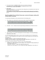
2.8
599 519 523 EN
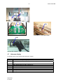
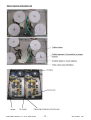
Control Point Illustrations
(2)
Terminal
1
2
3
4
5
Pin 1, 3
(1)
(5)
(3)
(4)
Air inlet
Min. 5 mm
Min. 20mm
Oven
Remark: if there is no ventilation gap in the front it’s still possible to operate the hob. Only with longer useage ( >15 min. ) the
performance will drop. For Mixed hob this is e.g. – 20%, for full induction hobs it’s higher.
DGS-TDS
21.04.08
14
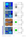
2.9
599 519 523 EN
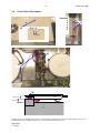
Images control point for 2 zones / Mixed Induction
(1)
(5)
(7)
(6)
(3)
Attention: mains connection for Domino is directly on filter pcb.
(1) Domino
(3)
(2)
DGS-TDS
21.04.08
15
599 519 523 EN
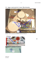
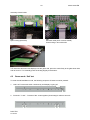
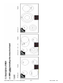
3 Testing Power Component
1. When alarm messages and disabled zones exist ("E“ in cooking phase display), please make
a note of the power component which is affected.
2. (7) Check whether the lead from the filter board is connected, also check the bus lines (6)
µprocessors filter to power component.
3. If (8) IGBT has become shorted, this normally means that the IGBT housing is damaged.
Replace power component
4. (8) Measure resistance at the IGBTs
Pin1-Pin2 or Pin2-Pin3
>50kOhm
Æ Okay
<50Ohm
Æ power component defect & replace
Only replace the affected power component and (9) insert 20A fuse, completely separate the
fuse strip conductor.
S12 = right power component
S11 = left power component
5. By a short-circuit and destroyed power component, it is imperative that the coil lines be
inspected for signs of damage.
6. Also replace the filterboard should the replacement of the power component not succeed.
(6)
(9)
(7)
(7)
(6)
(8) 8 St. IGBT
Pin 1 2 3
DGS-TDS
21.04.08
16
599 519 523 EN
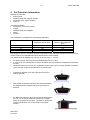
4 Pot Detection Information
Suitable pot materials:
• Steel enamel
• Stainless steel (with magnet. bottom)
• Aluminium (with magnet. bottom)
• Cast iron
Unsuitable materials:
• Aluminium (Æ too much power)
• Copper
• Stainless steel (not magnetic)
• Glass
• Ceramic
The pot detection is designed for the following diameters:
Nominal burner ∅ [mm]
Minimum pot bottom ∅
instruction manual [mm]
145
180
210
260
125
145
180
180
Minimum pot bottom ∅
adjusted with steel plate
[mm]
100
120
140
180
With regard to Ind. G4, the same diameter is stipulated in the instruction manuals as for the previous
model. However, the real diameter which still functions is much smaller.
The performance for different pots can very by as much as +/- 10-15%.
•
•
•
As reference pots, we recommend enamelled steel pots (e.g. Silit).
2-3 mm thick round steel plates in various diameters are very suitable for testing the pot detection
function.
Sandwich bottoms can cause very unpleasant noises if they are not correctly pressed. The same
is the case with regard to handles which are a little loose.
•
The bottom diameter of the pot is decisive and not the
exterior diameter.
•
With regard to stainless steel pots with sandwich bottoms,
the diameter of the magnetic part of the pot bottom is
decisive.
•
an additional influencing factor is the vertical distance from
the coil, i.e. an uneven sandwich bottom has a negative
effect on the power consumption. The effect is exactly the
same if the induction coil is not pressed on the glass
ceramic.
DGS-TDS
21.04.08
17
599 519 523 EN
5 Touch Control Autarkic Cooking Hobs Information
•
5.1
The Touch Control works on the basis of the infrared principle, i.e. a signal is transmitted with a
transmitter which is then reflected by the finger and received once more.
Instructions on the operation / possible operation errors if the buttons do
not function:
•
Do not use with the flat finger. Hold the finger relatively upright.
Otherwise 2 buttons can be activated, this is not signalled.
•
Please do not approach slowly, especially not from the side, it is better to approach the button
faster.
A signal change is above all evaluated.
•
Applying excessive pressure to the cooking hob will not make a difference.
It is better to release it for 5 sec. and then press the button again.
•
If the adjustment of the cooking stage/timer does not continue after the button has been released,
this is due to the fact that the Touch Control receives a "Button Pressed" signal even from a
distance of some mm.
If the user interface is not adjacent to the glass ceramic, the signal for the key evaluation is very
much smaller and the keys can not be operated any more, i.e. pay always attention to intact
plastic carriers.
•
If the appliance switches off without that the glass ceramic has been touched, is this because a
key in the extreme case.is switching even in a distance / height of 10 mm. This is the function
principle of the touch control and is a normal behaviour. I.e. do not replace the touch control!
DGS-TDS
21.04.08
18
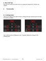
5.2
599 519 523 EN
Demo mode / Self test (Service mode) / Alarm Menu
To enter the self-test/Demo mode, the following sequence of buttons must be pressed:
1. Hob is off. Press main switch continuously until display is going off (without beep).
2. Press the "+" and " -" buttons of the front zones together (->short beep) for about 3 seconds (->
again short beep)
3. Press the timer selection key
Step 1
Step 3
d.
Step 2
4. The display shows a "d" for demo mode.
If you press the timer select key again you switch to “S” for Service mode,
another press gets you to “E” the alarm menu.
5. By pressing the button "+" of a cooking zone you activate the menu.
For example, status like above shown in the graphic – hob is in demo mode,
press ‘+’ key of zone to deactivate the demo mode.
Demo Mode:
If demo mode is activated the display with the „d“ shows additionally a dot.
After selecting the demo mode, the electronic goes to off. Now it can be used like usual but only
without heater activation. The deactivation of the demo mode is done in the same procedure as
activating. After deactivating the demo mode the electronic must go off. Now the hob can be used in
normal mode.
Service Mode “s”
Routine:
1. Test all LEDs / Displays for 10 Sec.
2. Show Software version Touch control for 10 Sec. in timer display
In the 7-Segment Display for zone right front (zone 4) an “0” is displayed as an indication that it is
step 0 – HUI.
3. Software display version power board.
Alarm Mode “E”
The last 5 stored alarm codes (if >o) are displayed like an actual alarm, each for 5 sec., starting with
the oldest (read request ‘5’ Alarm code message) to the newest (read request ‘1’).
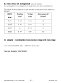
5.3
Product history
5.3.1 Change from automatic boost to manual boost
This change was done due to customer complaints. It was introduced in series production July2004.
The change is implemented with a modified configuration on the filter board of the induction.
DGS-TDS
21.04.08
19
599 519 523 EN
5.3.2 Error appliance can not be operated, display indicates "0"
This error has been disappeared after a reset.
For that there were 2 fault reasons in the hardware and software, this was removed by SW Vers. 4.2
from Dec. 2004.
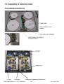
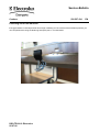
6 Frontline self-sufficient hobs
6.1
Special references disassembly/assembly in case of a service:
1. Disassemble appliance
Î Remove tension clips
2.
Open appliance
Î Attention! Before disassembling the glass draw off the connecting line between the user interface at the glass and
induction.
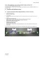
3. Replacement of display units
Î By means of a coin loosen plastic carriers by pressing and turning (29)
Î Shift back the plastic carrier until the front edge can be seen.
Î Lay plastic carrier to the bottom side
Î Remove locking bars like (30)
Î Draw off flat band cable
Î Replace electronic board
Î Assemble in the same way. Pay absolute attention to the correct putting and locking of the
band cable.
User interface and connection of two electronics at the glass ceramic (58 and 72 cm appliances)
(29)
(33) clamp bradings into the locking clips of the right carrier.
DGS-TDS
21.04.08
(33)
20
599 519 523 EN
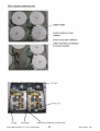
Assembly of band cable
(30)
Open locking (black bar)
(31)
Put band cable (silver contacts visible)
Close locking in arrow direction
(32)
Turn down the electronic with displays onto the glass side, press the carrier flatly to the glass lower side
and let it lock in. For assembly press the locking slightly to the bottom.
6.2
Demo mode / Self test
To enter the self-test/Demo mode, the following sequence of buttons must be pressed:
1. Hob is off. Press main switch continuously until display is going off.
2. Press the "+" and " -" buttons of the zones together (short beep) for about 3 seconds
DGS-TDS
21.04.08
21
599 519 523 EN
3. Then automatically the software version of the user interface is displayed,
for example „2“ „8“ = version 28 and all LEDs / Displays are ON for 10 Sec.
There is no alarm history mode available.
4. Demo mode
By pressing the button "A" / „P“ of one of the rear cooking zone you activate the demo mode, the
LED for Power function active is ON.
With activation of the demo mode the hob can be used like usual but without heater activation.
The deactivation of the demo mode is done in the same procedure as activating. The Led has to
be off.
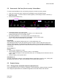
New Demo Mode/ Service Mode/ Alarm menu control philosophy starting with
October 2007 production
To access the self-test/demo mode, press the buttons in the following order:
1.
The cooking zone is switched off. Press the main switch until the display goes dark.
2.
Press the "+" and "-" buttons of the zones (short beep) simultaneously for about 3 seconds.
3.
After 3 seconds, a "d" for demo mode appears in the timer display or in the hot plate display
(depending on the model).
You can change between demo mode "d", service mode "S" and alarm menu "E" using the timer
button or "A" button (depending on the model). if you do not select anything, the unit will switch off.
Demo Mode „d“
Activation: Press the "+" button of the left-hand cooking zone
Indication in the timer display or in the cooking zones display (depending on the model): "do"
You can use the unit as usual, but without heater activation.
To be able to use the unit normally, you have to carry out the following steps:
Repeat 1. to 3.; after 3 seconds, the timer display or the cooking zones display (depending on
the model) indicates a "do".
Deactivation: press the "+" button of the left-hand cooking zone
Indication in the timer display or in the cooking zones display (depending on the model): "d"
DGS-TDS
21.04.08
SERVICE MANUAL
COOKERS
Cookers
© Electrolux Distriparts
Fürther Straße 246
D-90429 Nürnberg
Germany
DGS-TDS-N
Ausgabe: 10.09
Publ.-Nr.:
599 722 426
685
DE
New hob oven
combination
„Criss Cross“
DGS-TDS-N 04.09 U. H. / A. B. © Electrolux
-2-
599 717587
DE
DGS-TDS-N 04.09 U. H. / A. B. © Electrolux
-3-
599 717587
DE
DGS-TDS-N 04.09 U. H. / A. B. © Electrolux
-4-
599 717587
DE
DGS-TDS-N 04.09 U. H. / A. B. © Electrolux
-5-
599 717587
DE
DGS-TDS-N 04.09 U. H. / A. B. © Electrolux
-6-
599 717587
DE
DGS-TDS-N 04.09 U. H. / A. B. © Electrolux
-7-
599 717587
DE
DGS-TDS-N 04.09 U. H. / A. B. © Electrolux
-8-
599 717587
DE
DGS-TDS-N 04.09 U. H. / A. B. © Electrolux
-9-
599 717587
DE
DGS-TDS-N 04.09 U. H. / A. B. © Electrolux
- 10 -
599 717587
DE
DGS-TDS-N 04.09 U. H. / A. B. © Electrolux
- 11 -
599 717587
DE
DGS-TDS-N 04.09 U. H. / A. B. © Electrolux
- 12 -
599 717587
DE
Service Bulletin 599720823
DGS-TDS-N 04.09 U. H. / A. B. © Electrolux
- 13 -
599 717587
DE
Service-Bulletin
Cookers
599 525 778
EN
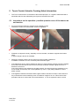
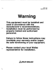
Induction hobs „G4“
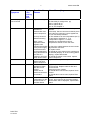
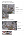
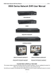
Problem description:
If you do not stick the transport safety adhesive on the coil connection cover after
repairs, the high-frequency magnetic field can lead to a temperature rise in the coil
area. The coil can be damaged by this. In order to eliminate this problem altogether,
you should not reapply the transport-safety adhesive tape after repairs.
Transport safety adhesive tape before repair
Do not apply adhesive tape after repair
The figure shows improper adhesion which may lead to damage from overheating of the coil located on top.
DGS-TDS-N © Electrolux
13.02.06
Service-Bulletin
Cookers
599 527 434
EN
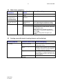
Fastening set for full induction
If the gap between countertop and hob is too large or differing or if the corners of the hob frame protrude, you
can compensate this using the fastening sets spare part no. 319 409 802/0.
DGS-TDS-N © Electrolux
05.07.06
Service-Bulletin
Cooking appliances
599 528 416
EN
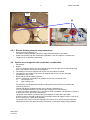
Scorch locations with plug connections
Problem:
Charred respectively burnt plugs/pin terminals with electronics and switches.
Reason:
Due to faulty crimpings or expanded plugs arise scorch locations within the area of the line
connection. When you leave the former plug in case of a service, e.g. when substituting a
defective electronic, this fault will repeat again in most cases.
Problem removal:
In case of scorch and fire locations respectively within the area of plug connections
you always have to replace the affected connectors.
That means, cut the plug at the corresponding braid (cable) and connect a new plug.
Leave the former plug at the pin terminal and return it, if possible unchanged and packed in
good condition, together with the defective spare part to the works in Rothenburg to the
following address
AEG Hausgeraete GmbH
Abt.: DGT-QZ zu Hd. H. Leis
Bodelschwingstr. 1
DE-91541 Rothenbiurg ob der Tauber
The required pliers and the plug-in sleeves can be obtained as spare parts.
SP No.
899 298 001 194/4
407 139812/9
899 298 001 301/5
899 298 001 302/3
DGS-TDS-N © Electrolux
14.02.07
Description
AMP pliers
Plug-in sleeve 4.8x0.8 St. nickelized 0.5-1.5mm²
Plug-in sleeve 6.3x0.8 St. nickelized 0.3-0.8mm²
Plug-in sleeve 6.3x0.8 St. nickelized 1.2-2.5mm²
SERVICE BULLETIN
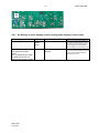
NOT CONFIGURED ELECTRONIC BOARDS (Rev. 02)
In the sections:
-
“Electrical equipment” in Washing machines, Washer-dryers, Dryers and Dishwashers spare part lists.
“Diffuser” or “Cooling Unit” in Refrigeration appliances.
the “configured electronic board”, identified by the first digits “973” of the spare part, is featured, where possible.
Also the “not configured electronic board” can be indicated in the same sections and with the same position.
The configuration of this board is possible only if you have the suitable equipment (software and hardware) for
this type of activity and if you have taken part to the training.
It is still not possible to programme the not configured electronic boards in all Countries.
ATTENTION:
We will not accept returns of not configured electronic boards that have been wrongly ordered or that are
damaged in some parts.
For any further question please contact your local Service Representative.
REVISIONS:
Revision
Date
00
05/2008
Document creation
01
06/2008
Updated text
02
11/2008
Updated document for use in Refrigeration appliances
EN
Description
Publication no.
599 70 81-16
Rev. 02
11/2008
PR
Service-Bulletin
Cookers
599 708 219
EN
Autark induction hob with „G4“ induction module
Switching of the output on and off with the selected power mode
G4 induction module
Problem description:
The induction module switches the power on and off with the selected power mode
(...“the cooking zone clocks“.). This mainly affects the cooking zones with diameters
of 210 mm and 280 mm.
Problem remedy:
In case of a failure, the performance electronic must be replaced in accordance with
the spare parts documentation.
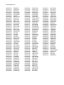
Affected serial numbers: 735.... up to including 826....
DGS-TDS-N © Electrolux
11.07.2008
Affected appliances:
949 592 213
949 592 215
949 592 235
949 592 242
949 592 243
949 592 260
949 592 264
949 592 325
949 592 326
949 592 327
949 592 328
949 592 329
949 592 330
949 592 331
949 592 332
949 592 333
949 592 375
949 592 383
949 592 399
949 592 400
949 592 467
949 592 468
949 592 470
949 592 472
949 592 492
949 592 495
949 592 496
949 592 498
949 592 499
949 592 502
949 592 503
949 592 505
949 592 506
949 592 507
949 592 508
949 592 509
949 592 510
949 592 546
949 592 547
949 592 548
949 592 549
949 592 586
949 592 591
949 592 592
949 592 593
949 592 598
949 592 618
949 592 619
949 592 620
949 592 622
949 592 660
949 592 661
ZKT 851DX
GK58TCICN
ZKT 651DX
ZKT 641DBV
ZKT 651DBV
68070 M-MN
GK78HIO
68001 KF-AN
68001 KF-N
68001 KF-N
68001 K-IN
68001 K-MN
68101KF-AN
68101K-MN
88101 KF-N
88101 K-MN
88101 K-IN
68001 K-MN
DIK 2492-UR
DIK 2491-UR
QHC 6501
QHC 8501
QHC 6501
QHC 8501
68001 K-MN
QHC 6501X
QHC 8501X
78001KF-MN
78001KF-N
QHC 7505
QHC 7505P
DIK 2470-UR
DIK 2470-RF
DIK 2470-AL
GK69TCICN
GK69TCIO
78001KF-N
KF-E7423
QHC 6503
EHD 6680P
EHD 7680P
EHD 60120X
EHD 60140I
EHD 80160I
EHD 80160P
AHD 68200P
JHD 60140X
JHD 60140I
JHD 80160X
JHD 68200P
EHD 60140P
EHD 60140X
949 592 662
949 592 663
949 592 664
949 592 665
949 592 666
949 592 671
949 592 672
949 592 695
949 592 696
949 592 697
949 592 698
949 592 700
949 592 709
949 592 710
949 592 711
949 592 725
949 592 727
949 592 741
949 592 742
949 592 743
949 592 744
949 592 745
949 592 750
949 592 761
949 592 762
949 592 763
949 592 764
949 592 765
949 592 766
949 592 768
949 592 775
949 592 780
949 592 781
949 592 782
949 592 783
949 592 785
949 592 786
949 592 787
949 592 788
949 592 790
949 592 857
949 592 858
949 592 859
949 592 860
949 592 861
949 592 862
949 592 863
949 592 864
949 592 866
949 592 867
949 592 869
949 592 870
EHD 60140P
EHD 60140P
EHD 60120P
EHD 80160P
EHD 80160P
EHD 68200P
EHD 68200P
AHD 60140P
AHD 60140OW
AHD 60120P
AHD 60120OW
EHD 60140P
78001K-MN
GK 624000IF
68072 M-MN
EHD 80160PX
EHD 68200PX
GK 583TCICN
GK 583TCIO
GK58TCICN
GK58TCIO
GK58TCIPCN
EHD 60120P
GK69HICN
GK69HIO
GK78HICN
GK78HIO
GK78TCIO
GK78TCICN
78000 KF-MN
88001KF-N
DIK 2480-UR
DIK 2480-RF
88001K-IN
88001K-MN
68000KF-N
78000KF-N
78001KF-MN
78001K-IN
68000 M-MN
68031 KF-AN
68031 KF-N
68031 KF-N
68031 K-IN
68031 K-MN
88031KF-N
88031K-MN
88031K-IN
DIK 3480-UR
DIK 3460-UR
QHC 8504P
QHC 8504P
949 592 871
949 592 872
949 592 873
949 592 874
949 592 877
949 592 878
949 592 879
949 592 880
949 592 881
949 592 882
949 592 884
949 592 888
949 592 889
949 592 890
949 592 896
949 592 908
949 592 916
949 592 919
949 592 920
949 592 921
949 592 922
949 592 923
949 592 924
949 592 925
949 592 926
949 592 932
949 592 933
949 592 957
949 592 958
949 592 959
949 592 976
949 592 977
949 592 978
949 592 979
949 592 990
949 592 991
949 592 994
949 593 003
949 593 053
68031 K-MN
QHC 8504X
QHC 6504N
EHD 60150I
JHD 60150X
JHD 60150I
JHD 80140X
EHD 60150P
EHD 60150X
EHD 60150P
AHD 60150P
GK58TCICN
GK58TCIO
GK58TCIPCN
68072 MF-N
JHD 80140P
JHD 80140I
JHD 68200X
JHD 68200I
JHD 80160P
JHD 80160I
EHD80180P
AHD60160P
EHD60160P
EHD60160P
JHD60160P
JHD80180P
ZKS851DX
ZKS651DBV
ZKS651DX
JLBIIH804
QHC 6504P
QHC 6504X
QHC 6504P
AHD 60150OW
AHD 60150S
68031SI
PAI8000E
ZKM8510DX
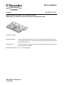
Service-Bulletin
Kochgeräte
599 720 823
DE
Neue Anschlußstecker Einbauherd/ Einbaukochfeld
Adapterlösung für ältere Geräte mit Wrasenaustritt (MEH)
Anschlußstecker ältere Kochfelder
mit Strahlungsbeheizung
Blauer Anschlußstecker
neue Einbauherde Exxx -6/ -7
Adapter ET.-Nr.: 561 023 700/9
Blauer Anschlußstecker neue Kochfelder
mit Strahlungsbeheizung
Anschlußstecker ältere Einbauherde
Exxx -5
Adapter ET.-Nr.: 561 023 600/1
DGS-TDS-N © Electrolux
29.07.2009
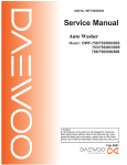
Operative Equipment Overview
EN
THE ITEM(s) SHOWN IN
THIS DRAWING MUST
NOT CONTAIN
FORMALDEHYDE,
CADMIUM, MERCURY,
ASBESTOS ORPBB/PBDO.
9
X1/
1
X1/
2
X1/
3
D
SAFETY RISKS
!
5
4
3
2
1
Induktionsmodul
induction module
X2
3pol
X1
X12
1
Bedienplatine rechts
user interface right
X14
Filterplatine
filter board
2
3
4
X9
X10
3
1
X13
1
2
3
4
X8
X7
1
3
X11
1
X4
X5
PE
X17
2
D
10pol
1
2
3
4
3
1
X10
X2
X1
Leistungsplatine / power board
links / left
1
: VISIBLE SURFACES
DRAFT ANGLES (NOT SHOWN): 00°00'00"
[2] CRITICAL DIMENSIONS WHICH
MUST BE UNDER CAPABILITY
6
E
X7
C
7
N2
THIS DRAWING CONTAINS CONFIDENTIAL INFORMATIONS.
IT'S PROPERTY OF ELECTROLUX WITHOUT WHOSE
PERMISSION IT MAY NOT BE COPIED, SHOWN OR HANDED
TO A THIRD PARTY OR OTHERWISE USED, AND IT IS TO
BE RETURNED PROMPTLY UPON REQUEST TO ELECTROLUX
WHICH IS RESPONIBLE FOR THE DRAWING.
E
8
X9
1
2
3
X8
X6
1
3
X10
X1
X2
Leistungsplatine / power board
rechts / right
2
X4
4
4
X5
X6
X8
M
3
X5
X9
X7
Bedienplatine links
user interface left
X4
C
Spulenträger / coil carrier
R
X1/
L
R
L
R
L
R
L
see respective wiring
diagram hob cpl.
siehe entprechenden
Verdrahtungsplan Mulde
komplett
4
X1/ 5
B
B
PE
-
DEVELOPED FLAT AREA
-
THEORETICAL FLAT AREA
X1/
Lüfter
fan
Leistungsplatine
power board
Filterplatine
filter board
Leistungsplatine
power board
A
first edition
Weiß
links
left
LENGTHS AND DIAMETERS:
<18 mm.
: ±--18 - 80 mm. : ±-->80 mm.
: ±---
: ±--*
ANGLES
A
GENERAL TOLERANCES
ZUST
2
3
rechts
right
DESIGN
MODIFICATIONS
OWNER
DATE
CHD
DGR-PE_PD
4
Weiß
TITLE
circuit diagram induction G4 (split)
Schaltplan Induktion G4 (split)
NUMBER
7
DATE
USERS
EUROPEAN
METHOD
2005-03-21
APPR
A4
8
2005-03-21
REQUEST
DESIGN
TITEL
9
DGT 26149
Weiß
DGT
1
DRN
SIGNATURE
6
5
4
3
387 0608
2
SHEET
REV
01(01)
1
A
A