1
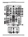
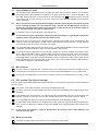
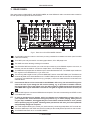
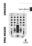
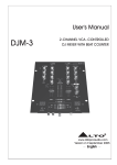
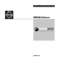
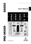
Version 1.0 July 2001 www.behringer.com ENGLISH VMX200 PRO MIXER Users Manual PRO MIXER VMX200 SAFETY INSTRUCTIONS CAUTION: To reduce the risk of electric shock, do not remove the cover (or back). No user serviceable parts inside; refer servicing to qualified personnel. WARNING: To reduce the risk of fire or electric shock, do not expose this appliance to rain or moisture. This symbol, wherever it appears, alerts you to the presence of uninsulated dangerous voltage inside the enclosurevoltage that may be sufficient to constitute a risk of shock. This symbol, wherever it appears, alerts you to important operating and maintenance instructions in the accompanying literature. Read the manual. DETAILED SAFETY INSTRUCTIONS: All the safety and operation instructions should be read before the appliance is operated. Retain Instructions: The safety and operating instructions should be retained for future reference. Heed Warnings: All warnings on the appliance and in the operating instructions should be adhered to. Follow instructions: All operation and user instructions should be followed. Water and Moisture: The appliance should not be used near water (e.g. near a bathtub, washbowl, kitchen sink, laundry tub, in a wet basement, or near a swimming pool etc.). Ventilation: The appliance should be situated so that its location or position does not interfere with its proper ventilation. For example, the appliance should not be situated on a bed, sofa, rug, or similar surface that may block the ventilation openings, or placed in a built-in installation, such as a bookcase or cabinet that may impede the flow of air through the ventilation openings. Heat: The appliance should be situated away from heat sources such as radiators, heat registers, stoves, or other appliances (including amplifiers) that produce heat. Power Source: The appliance should be connected to a power supply only of the type described in the operating instructions or as marked on the appliance. Grounding or Polarization: Precautions should be taken so that the grounding or polarization means of an appliance is not defeated. Power-Cord Protection: Power supply cords should be routed so that they are not likely to be walked on or pinched by items placed upon or against them, paying particular attention to cords and plugs, convenience receptacles and the point where they exit from the appliance. Cleaning: The appliance should be cleaned only as recommended by the manufacturer. Non-use Periods: The power cord of the appliance should be unplugged from the outlet when left unused for a long period of time. Debris and Liquid Entry: Care should be taken that debris and/or liquids do not enter the enclosure through openings. Damage Requiring Service: The appliance should be serviced by qualified service personnel when: - The power supply cord or the plug has been damaged; or - Debris or liquid has entered the appliance; or - The appliance has been exposed to rain; or - The appliance does not appear to operate normally or exhibits a marked change in performance; or - The appliance has been dropped, or the enclosure damaged. Servicing: The user should not attempt to service the appliance beyond that which is described in the operating instructions. All other servicing should be referred to qualified service personnel. 2 PRO MIXER VMX200 FOREWORD Dear Customer, Welcome to the team of PRO MIXER users and thank you for demonstrating your faith in us by purchasing the BEHRINGER VMX200. Writing this foreword to you is an extremely pleasant task. After several months of intensive brainstorming and the subsequent realization of their ideas, our engineers finally achieved an ambitious goal: the construction of an outstanding DJ MIXER, which, due to its remarkable functions, provides maximum flexibility and impressive performance. As with any new product, the development of this new PRO MIXER also meant a great deal of responsibility. Throughout the entire planning and development phases, we kept youthe discerning end-user and DJ, your requirements and your requests at the focal point of our considerations. Meeting your professional expectations required a lot of effort and more than a few night shifts, but this is exactly the kind of challenge that keeps us alive and kicking. Developing a new product always brings a large number of people together, and its a great feeling when all involved can take pride in the results. It is an important part of our philosophy to share our gratification with you, since youre the most important member of the BEHRINGER team. With your highly competent suggestions for new products, youve contributed immensely to the development and success of our company. In return, we bring you uncompromising quality, guaranteed by the stringent BEHRINGER quality control system, as well as excellent technical and audio specifications, at an extremely favorable price. We hope that this will enable you to fully unfold your creativity without being hampered by budget constraints. We are often asked how we manage to produce such high-grade devices at such unbelievably low prices. The answer is quite simple: its you, our customers! Lots of satisfied customers means large sales volumes, which in turn enables us to reduce production and logistics expenses. We believe its only fair to pass this benefit back to youafter all, your success is our success! I would like to thank everyone who helped make our new PRO MIXER project possible and successful. Each of those people made very personal contributions, from our engineers and designers to our numerous staff members and finally to you as a BEHRINGER user. My friends, its been worth the trouble! Thank you very much, Uli Behringer 3 PRO MIXER VMX200 PRO MIXER Professional 2-channel ultra low-noise DJ mixer s Super-smooth Ultraglide faders with up to 500,000 life cycles s Awesome QRS 3D surround effect s Dedicated curve control for all faders s VCA engines for utmost reliability and smooth audio performance s Gain and 3-band kill EQ (-32 dB) per stereo channel s Auto-talkover function with separate depth control s Extremely precise assignable level meter with peak hold function s Professional crossfader reverse switch VMX200 s Intelligent dual auto-BPM counter with time and beat sync display s Extremely low-noise ULN-(Ultra-Low Noise) design, like those on professional studio consoles s Gold-plated cinch sockets for excellent audio qualities s Super-rugged construction ensures long life, even under the most demanding conditions s Manufactured under ISO9000 certified management system 4 PRO MIXER VMX200 TABLE OF CONTENTS 1. INTRODUCTION..................................................................................................................... 5 1.1 Before you get started ..................................................................................................................... 5 2. FRONT PANEL ........................................................................................................................ 6 2.1 2.2 2.3 2.4 2.5 2.6 2.7 Input channels 1 and 2 .................................................................................................................... Mic channel .................................................................................................................................... PFL section (Pre-Fader Listening) ................................................................................................... Main out section ............................................................................................................................. QRS-3D surround function ............................................................................................................... Beat counter ................................................................................................................................... Crossfader section .......................................................................................................................... 7 7 7 7 8 8 8 3. REAR PANEL ........................................................................................................................... 9 4. SPECIFICATIONS .................................................................................................................. 11 5. WARRANTY ........................................................................................................................... 12 1. INTRODUCTION With the BEHRINGER PRO MIXER VMX200, you have purchased an absolutely state-of-the-art DJ mixer. Its extensive features, i.e. beat counter and effects loop, open the door to new and creative ways of working, while making it suitable for a variety of professional applications. At the same time, the VMX200 is extremely easy to operate, allowing you to completely unfold your creativity. Time waits for no one, and neither you nor we want to be left behind. Thats why we invested months of research and development into creating a DJ mixer that offers up-to-date features and technology to give you a true cutting edge for your performances. Fully optimized for dance club applications and DJ systems, the VMX200 promises full-blown DJing funand success. Lets be honest: nobody likes reading users manuals. We know you want to plug in and get jammin, but please take the time to read the following instructions. Weve kept them as short as possible, and it will be well worth the few minutes it takes you. Armed with a thorough understanding of the VMX200s features and functions, youll be able to get the most out of this exciting product. + The following instructions will give you a brief run-down on the terminology and functions of the VMX200. After reading, please store this manual in a safe place for future reference. 1.1 Before you get started Your PRO MIXER was carefully packed in the factory and the packaging is designed to protect the unit against rough handling. Nevertheless, we recommend that you carefully examine packaging and contents for any signs of physical damage which may have occurred during transit. + If the unit is damaged, please do not return it to BEHRINGER, but notify your dealer and the shipping company immediately. Otherwise, claims for damage or replacement may not be granted. Shipping claims must be made by the consignee. Please take care to always ensure adequate ventilation. Do not place the PRO MIXER near heating units or heat-generating devices in order to avoid overheating. CAUTION! + We would like to point out that high volumes can permanently damage your sense of hearing and/or your headphone or speaker systems. Therefore, please turn the MAIN control in the MIC/MAIN section all the way to the left before turning on the mixer. And please exercise caution and common sense when setting volume levels. 1. INTRODUCTION 5 PRO MIXER VMX200 2. FRONT PANEL Fig. 2.1 Front view of the PRO MIXER VMX200 6 2. FRONT PANEL PRO MIXER VMX200 2.1 Input channels 1 and 2 1 + 2 + The PHONO-LINE/LINE switch selects one of the input pairs on the respective channel. The PHONO setting (and inputs) are intended for turntables; for all other signal sources, i.e. a CD or MD player, use the LINE setting and inputs. A second switch on the rear panel (see ) enables the phono input pair to be switched to line level, allowing 2 line-level units to be connected and selected via the PHONOLINE/LINE switch. Never connect line-level equipment to the highly sensitive phono inputs! The output levels of phono cartridge systems are in the millivolt range, whereas CD and MD players, as well as tape decks, provide outputs levels in the volt range. In other words, the level of line signals is up to 100 times higher than phono output levels. The GAIN control is used to adjust the input signal level. The overall level of your signal is also effected by the EQ settings. Its a good idea to adjust the equalizer before you set the level with the GAIN control. 3 Each of the two input channels is equipped with a 3-BAND EQUALIZER with kill characteristic. The maximum amount of attenuation (-32 dB) is much higher than the maximum boost (+12 dB), allowing entire frequency spectrums to be removed from a track. 4 The CHANNEL fader adjusts the final channel volume. The ULTRAGLIDE fader is VCA-controlled (VCA = Voltage-Controlled Amplifier) to ensure smooth operation and long life. 5 The CURVE switch underneath the channel fader enables you to select between three fade modes: SOFT, MID and SHARP. In SOFT mode the fader controls the volume in a linear, continuous manner. Run a track through on of the VMX200s channels and pull the fader down slowly: the volume will decrease gradually. In SHARP mode the fader takes on a more logarithmic effect, reducing the volume faster towards the lower end of the fader range, even if you move the fader smoothly. MID mode is a combination of the SOFT and SHARP modes. 2.2 Mic channel 6 The mic section is equipped with a 2-BAND (HIGH and LOW) EQUALIZER with standard (not kill) characteristics, allowing you to fine-tune your microphone signal and adapt it to your overall sound. 7 The LEVEL control adjusts the volume of the microphone signal. The ON switch puts you on air (or off). 2.3 PFL section (Pre-Fader Listening) The PFL signal is a pre-fader headphones signal, enabling you to pre-listen to a signal source without effecting the main signal. 8 The LEVEL control determines the volume of the headphones signal. 9 The MIX control lets you fade between channels 1 and 2 when the MODE switch (see below) is set to STEREO. 10 It the MODE switch is set to SPLIT, the channels are strictly separated: channel 1 will be heard on the left side, channel 2 on the right. In this mode, the MIX control has no influence on the PFL signal. 11 The LEVEL METER displays the level of the signal selected via the MAIN/PFL button. 12 The MAIN/PFL button allows you to route either the main or the PFL signal to the display. Remember: PFL is your pre-listening or headphone signal and MAIN is the signal assigned to the outputs of the VMX200. + In PFL mode, the channel 1 signal is displayed on the left side of the LEVEL METER, and channel 2 on the right. 2.4 Main out section 13 The main out section also has a LEVEL control to adjust the output level. 2. FRONT PANEL 7 PRO MIXER VMX200 14 2.5 The PRO MIXER VMX200 is equipped with a talkover function, which works very simply: if you speak into the microphone while a track is running, the volume of the music is automatically reduced, so that your voice is always in front. The TALK control allows you to determine how much the music volume is lowered (max. -24 dB). 3D surround function The built-in QRS effect widens the stereo image and adds life and transparency to your soundan easy way to put a unique final polish on your music and turn your performance into an incomparable experience. The SURROUND control determines the intensity of the effect, which can be turned on and off via the ON button. 2.6 Beat counter The PRO MIXER VMX200s built-in beat counter is an extremely useful feature, allowing smooth crossfades between two tracksan important key to the success of your performance. The beat counter analyzes and displays the tempi of your tracks in BPM (Beats Per Minute). The beat counter sections of channel 1 and 2 are identical. . In the case of multiple tempo The tempo of the track is shown in the respective channels DISPLAY changes, the display would change continuously, causing unnecessary confusion and rendering the function virtually useless. Enter the SYNC LOCK button : with it, you can limit the range of possible tempo values within a song. Pressing this button once the counter has caught and displayed a realistic value will simplify things. The BEAT ASSIST button allows you to set the beat counters tempo manually, similar to tap tempo. Pressing the button three times in time with the track will set the beat counter and its display at that tempo. The BEAT ASSISST and SYNC LOCK buttons are each equipped with an LED to show that the respective function is activated. Once the tempo of the two tracks have been determined and locked with the SYNC LOCK or BEAT ASSIST buttons, the tempo difference between channel 1 and 2 will be depicted via the 9-segment TEMPO DIFFERENCE LED display . It shows the degree of the tempo difference by a respective deflection to the right (channel 2 track is faster) or to the left (channel 2 track is faster). The center LED lights when the tempi are equal. The synchronization of channel 1 and 2 is shown in the TIME OFFSET LED display below the TEMPO DIFFERENCE display. When the center LED is lit, the tracks are in sync with each other. When the display moves to the left or right, the corresponding channel is running out of sync. The TEMPO DIFFERENCE and TIME OFFSET displays are only active when the tempi of both channels have been locked as explained above. To exit the SYNC LOCK or BEAT ASSIST mode, simply press the SYNC LOCK key in both channels again. 2.7 Crossfader section 21 The CROSSFADER is used to fade between channels 1 and 2. Like the channel faders, the crossfader section is equipped with a 45-mm VCA-controlled ULTRAGLIDE fader. 22 The REVERSE switch enables you to invert the direction of the crossfader, so that you can quickly switch from channel 1 to channel 2. This effect is created by simply pushing the REVERSE switch down (TAP)as soon as it is released, it returns to its original position and your crossfade setting (and your music) is at it was before. Pressed upwards, the switch locks into the reversed position (HOLD). To reset it, simply push it downwards. 23 The CROSSFADER CURVE control in the crossfader section is similar to the CURVE switches in channels 1 and 2 (see ). The control allows you to fade between the various crossfader curve modes. 24 The MIC INPUT connector is a balanced ¼" TRS socket for microphone connection. + 25 8 We strongly recommend the use of high-grade cables and connectors for the transmission of audio signals. Inferior quality materials cannot supply acceptable audio quality or corrosion protection. The HEADPHONES socket allows you to connect your headphones for pre-listening (PFL signal). For best results, use headphones with an impedance rating of at least 32 Ohms. 2. FRONT PANEL PRO MIXER VMX200 3. REAR PANEL With the exception of MIC INPUT and HEADPHONES, all of the VMX200s audio connections are located on the rear panel and supplied as RCA connectors. Fig 3.1: Rear view of the PRO MIXER VMX200 26 The PHONO inputs for channel 1 and 2 are primarily intended for turntable connection (see PHONO/ LINE switch below). 27 The LINE inputs may be used for connecting tape decks, CD or MD players etc. 28 The GND connection allows grounding of a turntable. 29 The PHONO/LINE switch allows you to set the input sensitivity of the PHONO inputs to line level, so that they can also be used for connection of tape decks, CD or MD players etc. 30 The VMX200 is equipped with an effects loop for external effects devices. The SEND output sends the PFL signal to a connected device, e.g. a reverb unit. 31 The resulting effect signal can be input to the MAIN OUT section via the RETURN input. The effect level must be adjusted on the external effects unit. The RETURN input can also be used as an extra input for connection of an additional signal source (e.g. sampler)also in this case the level must be set on the external device. + 32 + 33 34 If an external effects unit is connected via the VMX200s effect loop, the selected PFL signal is sent to the unit. If you change the PFL section setting, e.g. to pre-listen to another channel, that signal will be sent to the effects unitthe effect signal of a different track will be mixed to your MAIN OUT signal. Remember: the effects unit gets its signal from the PFL section (see ). Use the AMP output to connect the VMX200 to an amplifier. The level is controlled by the LEVEL control in the MAIN OUT section. In order to avoid power-up thumps, which can damage your loudspeakers, please power up your amplifier last. There should be no signal present, e.g. no music playing, when you turn on your amp. In addition, we suggest that you set all volume-related controls to zero (down) before powering up your system. Following these precautions will save you from unpleasant and potentially dangerous surprises. The TAPE output enables you to record your performance by connecting a tape deck, DAT recorder etc. Unlike the AMP output, the TAPE level is fixed, so that you have to adjust the input level on the recorder. The POWER ON switch turns on the PRO MIXER. 3. REAR PANEL 9 PRO MIXER VMX200 35 + 36 37 10 FUSE HOLDER/VOLTAGE SELECTOR. Before you connect the equipment to an AC outlet, please be sure that the voltage displayed corresponds with your local AC voltage. If you should need to replace the fuse, be sure to replace it with one of the same type and value. Some units allow you to switch between 230 V and 115 V by rotating the fuse holder. Note: To operate the unit at 115 V, you must install a fuse with the double ampere rating. This is the socket for the power cable. The impulse behavior of any given amplifier circuit depends largely upon the power supplys inherent reserves. All mixers contain numerous operational amplifiers (op-amps) for processing line-level signals. Due to the restricted performance of their power supplies, many mixers show stress symptoms when used under extreme conditions, resulting in inferior audio quality. Thanks to its generously proportioned power supply, this will never happen to your VMX200: The sound will always be clear, transparent and powerful. SERIAL NUMBER. Please take the time to fill out and return the warranty card within 14 days after the date of purchase. This will entitle you to all the benefits of our extended warranty. Alternatively, you can register online at www.behringer.com. 3. REAR PANEL PRO MIXER VMX200 4. SPECIFICATIONS AUDIO INPUTS Mic input Phono inputs 1 and 2 Line inputs 1 and 2 Return 40 dB gain, servo-balanced 40 dB gain @ 1 kHz, unbalanced 0 dB Gain, unbalanced 0 dB Gain, unbalanced AUDIO OUTPUTS Main Out Tape Out Send Headphones max. +21 dBu @ +10 dBu (Line In) typically 0 dBu typically 0 dBu typically 125mW @ 1 % THD EQUALIZER (+/-8 dB) Stereo Low Stereo Mid Stereo High Mic Low Mic High +12 dB/-32 dB @ 50 Hz +12 dB/-32 dB @ 1,2 Hz +12 dB/-32 dB @ 10 kHz +12 dB/-12 dB @ 50 Hz +12 dB/-12 dB @ 10 kHz GENERAL Signal-to-noise ratio (S/N) Crosstalk Distortion (THD) Frequency response Input gain adjustment > 86 dB (Line) > 77 dB (Line) < 0,06 % 20 Hz - 20 kHz -20 dB - +9 dB POWER SUPPLY AC voltage USA/Canada U.K./Australia Europe DIMENSIONS AND WEIGHT Dimensions (H x W x D) Weight 120 V ~, 60 Hz, fuse T 400 mA H 240 V ~, 50 Hz, fuse T 250 mA H 230 V ~, 50 Hz, fuse T 250 mA H approx. 3 1/2" (88 mm) x 8" (203 mm) x 11" (280 mm) approx. 2.5 kg (5 lbs. 8 oz) BEHRINGER is constantly striving to maintain the highest professional standards. As a result of these efforts, modifications may be made from time to time to existing products without prior notice. Specifications and appearance may differ from those listed or illustrated. 4. SPECIFICATIONS 11 PRO MIXER VMX200 5. WARRANTY § 1 WARRANTY CARD/ONLINE REGISTRATION To be protected by the extended warranty, the buyer must complete and return the enclosed warranty card within 14 days of the date of purchase to BEHRINGER Spezielle Studiotechnik GmbH, in accordance with the conditions stipulated in § 3. Failure to return the card in due time (date as per postmark) will void any extended warranty claims. Based on the conditions herein, the buyer may also choose to use the online registration option via the Internet (www.behringer.com or www.behringer.de). § 2 WARRANTY 1. BEHRINGER (BEHRINGER Spezielle Studiotechnik GmbH including all BEHRINGER subsidiaries listed on the enclosed page, except BEHRINGER Japan) warrants the mechanical and electronic components of this product to be free of defects in material and workmanship for a period of one (1) year from the original date of purchase, in accordance with the warranty regulations described below. If the product shows any defects within the specified warranty period that are not due to normal wear and tear and/or improper handling by the user, BEHRINGER shall, at its sole discretion, either repair or replace the product. 2. If the warranty claim proves to be justified, the product will be returned to the user freight prepaid. 3. Warranty claims other than those indicated above are expressly excluded. § 3 RETURN AUTHORIZATION NUMBER 1. To obtain warranty service, the buyer (or his authorized dealer) must call BEHRINGER (see enclosed list) during normal business hours BEFORE returning the product. All inquiries must be accompanied by a description of the problem. BEHRINGER will then issue a return authorization number. 2. Subsequently, the product must be returned in its original shipping carton, together with the return authorization number to the address indicated by BEHRINGER. 3. Shipments without freight prepaid will not be accepted. § 4 WARRANTY REGULATIONS 1. Warranty services will be furnished only if the product is accompanied by a copy of the original retail dealers invoice. Any product deemed eligible for repair or replacement by BEHRINGER under the terms of this warranty will be repaired or replaced within 30 days of receipt of the product at BEHRINGER. 2. If the product needs to be modified or adapted in order to comply with applicable technical or safety standards on a national or local level, in any country which is not the country for which the product was originally developed and manufactured, this modification/adaptation shall not be considered a defect in materials or workmanship. The warranty does not cover any such modification/adaptation, irrespective of whether it was carried out properly or not. Under the terms of this warranty, BEHRINGER shall not be held responsible for any cost resulting from such a modification/adaptation. 3. Free inspections and maintenance/repair work are expressly excluded from this warranty, in particular, if caused by improper handling of the product by the user. This also applies to defects caused by normal wear and tear, in particular, of faders, potentiometers, keys/buttons and similar parts. 4. Damages/defects caused by the following conditions are not covered by this warranty: s misuse, neglect or failure to operate the unit in compliance with the instructions given in BEHRINGER user or service manuals. s connection or operation of the unit in any way that does not comply with the technical or safety regulations applicable in the country where the product is used. s damages/defects caused by force majeure or any other condition that is beyond the control of BEHRINGER. 5. Any repair or opening of the unit carried out by unauthorized personnel (user included) will void the warranty. 6. If an inspection of the product by BEHRINGER shows that the defect in question is not covered by the warranty, the inspection costs are payable by the customer. 7. Products which do not meet the terms of this warranty will be repaired exclusively at the buyers expense. BEHRINGER will inform the buyer of any such circumstance. If the buyer fails to submit a written repair order within 6 weeks after notification, BEHRINGER will return the unit C.O.D. with a separate invoice for freight and packing. Such costs will also be invoiced separately when the buyer has sent in a written repair order. § 5 WARRANTY TRANSFERABILITY This warranty is extended exclusively to the original buyer (customer of retail dealer) and is not transferable to anyone who may subsequently purchase this product. No other person (retail dealer, etc.) shall be entitled to give any warranty promise on behalf of BEHRINGER. § 6 CLAIM FOR DAMAGES Failure of BEHRINGER to provide proper warranty service shall not entitle the buyer to claim (consequential) damages. In no event shall the liability of BEHRINGER exceed the invoiced value of the product. § 7 OTHER WARRANTY RIGHTS AND NATIONAL LAW 1. This warranty does not exclude or limit the buyers statutory rights provided by national law, in particular, any such rights against the seller that arise from a legally effective purchase contract. 2. The warranty regulations mentioned herein are applicable unless they constitute an infringement of national warranty law. The information contained in this manual is subject to change without notice. No part of this manual may be reproduced or transmitted in any form or by any means, electronic or mechanical, including photocopying and recording of any kind, for any purpose, without the express written permission of BEHRINGER Spezielle Studiotechnik GmbH. BEHRINGER is a registered trademark. ALL RIGHTS RESERVED. © 2001 BEHRINGER Spezielle Studiotechnik GmbH. BEHRINGER Spezielle Studiotechnik GmbH, Hanns-Martin-Schleyer-Str. 36-38, 47877 Willich-Münchheide II, Germany Tel. +49 (0) 21 54 / 92 06-0, Fax +49 (0) 21 54 / 92 06-30 12 5. WARRANTY FEDERAL COMMUNICATIONS COMMISSION COMPLIANCE INFORMATION PRO MIXER VMX200 Responsible party name: MUSIC Group Services USA, Inc. Address: 18912 North Creek Parkway, Suite 200 Bothell, WA 98011, USA Phone/Fax No.: Phone: +1 425 672 0816 Fax: +1 425 673 7647 PRO MIXER VMX200 complies with the FCC rules as mentioned in the following paragraph: This equipment has been tested and found to comply with the limits for a Class B digital device, pursuant to part 15 of the FCC Rules. These limits are designed to provide reasonable protection against harmful interference in a residential installation. This equipment generates, uses and can radiate radio frequency energy and, if not installed and used in accordance with the instructions, may cause harmful interference to radio communications. However, there is no guarantee that interference will not occur in a particular installation. If this equipment does cause harmful interference to radio or television reception, which can be determined by turning the equipment off and on, the user is encouraged to try to correct the interference by one or more of the following measures: • Reorient or relocate the receiving antenna. • Increase the separation between the equipment and receiver. • Connect the equipment into an outlet on a circuit different from that to which the receiver is connected. • Consult the dealer or an experienced radio/TV technician for help. This device complies with Part 15 of the FCC rules. Operation is subject to the following two conditions: (1) this device may not cause harmful interference, and (2) this device must accept any interference received, including interference that may cause undesired operation. Important information: Changes or modifications to the equipment not expressly approved by MUSIC Group can void the user’s authority to use the equipment. behringer.com