1
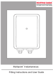
Handy Dri 24
Fitting Instructions and User Guide
Please read and understand these instructions prior to
installing your Handy Dri hand drier. They are for use by
competent personnel i.e. trained, experienced and
qualified. Instructions only detail key operations. They do
not supersede national, mandatory or legal requirements
which may apply to the product, installation, environment
or personnel associated with servicing the Handy Dri.
Particular attention should be paid to the section headed
IMPORTANT INSTALLATION POINTS. Following
installation and commissioning, the operation of the hand
drier should be explained to the customer and these
instructions left with them for future reference.
TECHNICAL SPECIFICATIONS
Voltage
Frequency
Rated power
Heating element power
Motor input power
Noise level
Air volume
Air temperature rise
Electrical class
Ingress protection
Dimensions
Weight (Net)
230V - 240V
50Hz - 60Hz
2400W
2200W
200W
80± 3dB(A)
51 l/s
35 K measured 50mm from
the outlet
1
IPX1
284 W x 248 H x 202 D
6.6kg
1.0 SAFETY INSTRUCTIONS
1.1
1.2
Always disconnect from the mains before removing the
cover.
Do not run the Handy Dri with the cover removed or the
motor will not be effectively cooled.
Please note that improper use of electrical appliances can give
rise to hazards that children can not recognise.
2.0 IMPORTANT INSTALLATION
POINTS
2.1
2.2
2.3
2.4
2.5
Check the mains electrical supply is within the range 230V
to 240V 50/60Hz before connecting the Handy Dri.
The Handy Dri must be installed by a qualified electrician.
The Handy Dri is intended for wall mounting only.
The Handy Dri should be mounted at least 600mm away
from any sink or wash basin.
All electrical work must comply with the relevant parts of
both the latest BS7671(IEE Wiring Regulations) and part
P Building Regulations. Special requirements must be
observed when installed in bathrooms etc.
3.0 INSTALLATION WALL MOUNTING
3.1
3.2
3.3
3.4
3.5
To remove the cover:
Completely unscrew the two screws located on the
underside of the unit, using the special hexagon wrench
supplied.
Lift the cover away from the backplate, and over the
sensor housing, before removing the cover completely.
Choose the mounting position for the Handy Dri taking
into account :
• The position of the electrical connection.
• The recommended height, (see the mounting
template).
• A distance of 150mm must be left between each
unit to allow access for servicing.
• The Handy Dri must not be installed in zone 2
situations (Part P) eg. within 600mm of a bath,
sink, basin etc.
• The Handy Dri must be mounted at least 250 mm
above any surface.
Ensure that the wall can support the weight of the unit
(see TECHNICAL SPECIFICATIONS) and that there are
no hidden services (electricity, gas or water) below
surface of the wall.
Using the template, mark the fixing positions, drill positions
with an 8mm drill, plug and screw into position (confirm
suitability of all screws and plugs for use with the
wall, if unsuitable due to wall type provide alternative
fixings).
4.0 INSTALLATION ELECTRICAL REQUIREMENTS
WARNING: This appliance must be earthed. It is suitable
for a.c. supply only. Disconnect the electrical supply
before removing the cover. Installation must be in
accordance with the current local Wiring Regulations.
4.1 A double pole isolating switch, with a contact separation of
at least 3mm in both poles, should be incorporated in the
electrical supply. The supply should be fused 13 Amp.
4.2 The nominal cross sectional area of the supply cable
should be 1.5mm2 minimum.
4.3 The unit can be connected using fixed wiring brought in
through the rear of the unit, or using a flexible cord through
the bottom of the unit.
4.4 Where the cable enters from the bottom it must pass
through the cable bushing. If wired from the rear, the cable
bushing must be exchanged with the blank bushing in the
backplate. Bushings are removed by depressing the
securing tabs built into them.
4.5 Strip the sheath of the flexible cord so that when the
conductors are connected to the terminals the sheath is
still gripped in the cable bushing.
4.6 Where fixed wiring is used, sleeve the bare circuit
protective conductor with green/yellow sleeving.
Make the electrical connections.
BROWN or RED to the terminal block marked “L”
BLUE or BLACK to the terminal block marked “N”
GREEN/YELLOW or bare to terminal on the base plate
marked .
Figure 1: Wiring Diagram
Sensor
7
Schematic Circuit Diagram
6
5
M
4
Timer
Motor
Heater
2
Relay Contact
3
1
Thermostat
L
N
5.0 OPERATION
5.1
5.2
5.3
The Handy Dri is fitted with an infrared system which
detects the presence of the hands.
To turn the unit on place the hands 10 to 30 cm below the
air nozzle and the unit will automatically start.
When the hands are withdrawn the unit will automatically
stop.
6.0 MAINTENANCE
6.1
6.2
To keep the Handy Dri operating efficiently and to prolong
the life, the inlet grill and outlet nozzle should be regularly
vacuumed.
The outer case should be cleaned using a proprietary
cleaner suitable for the surface finish.
7.0 SPARE PARTS
Item
Fan Blade
Fan Enclosure A
Fan Enclosure B
Timer Assembly
Heater Assembly
Air Outlet Holder
Sensor Rubber
Motor Rubber
Air Outlet Rubber
Motor
Sensor
Thermostat
Motor Brushes
Product Code
95607171
95607172
95607173
95607174
95607175
95607176
95607177
95611010
95611011
95612022
95612023
95612025
95612024
8.0 FAULT FINDING
SAFETY NOTE: DISCONNECT THE ELECTRICAL
SUPPLY BEFORE REMOVING THE COVER. DO NOT
BYPASS ANY SAFETY CONTROLS
SYMPTOM
Unit does not
turn on.
POSSIBLE CAUSE
ACTION
1. Local switch off.
2. Local fuse blown.
3. Circuit breaker at main
board off.
4. Sensor not fully located
in the front cover.
5. Sensor wire
disconnected.
6. Motor fuse and thermal
fuse blown.
7. Thermostat faulty.
1. Turn local switch on.
2. Replace local fuse.
3. Re-set breaker.
Motor runs
intermittently.
1. Brushes worn.
1. Replace brushes.
Airflow is cold
continuously.
1. Element fault.
1. Replace heating
element assembly.
4. Relocate sensor.
5. Check connections to
pcb and sensor.
6. Replace motor.
7.Replace thermostat.
No airflow and 1. Motor fuse blown.
elements cycle
hot and cold.
1. Replace motor.
Unit runs
continuously.
1. Reposition unit or
reflective surface.
1. Reflective surface less
than 250mm below
sensor.
9.0 GUARANTEE
The Handy Dri 24 is guaranteed for a period of five years from
the date of purchase provided:
1. The unit has been installed in accordance with these
instructions.
2. The unit has not been tampered with and has been
regularly maintained as detailed in the maintenance
instructions.
The guarantee excludes normal motor brush wear and tear.
This guarantee does not affect the statutory rights of the
consumer.
10.0 Environmental Information
Old appliances contain valuable materials that
can be recycled. Do not dispose of such
appliances with normal domestic waste but
rather by way of appropriate collecting points.
NOTES
Spares Stockists
For the fast and efficient supply of spares please contact the stockists
listed below.
Parts Center
PO Box 48, Tomlinson Road, Leyland, Preston, Lancashire, PR5 1JX
Tel: 01772 819671
www.partscenter.co.uk
Electric Water Heating Co
2 Horsecroft Place, Pinnacles, Harlow, CM19 5BT
Tel 0845 0553811
Email : [email protected]
SPD Special Product Division
Unit 9 & 10, Hexagon Business Centre, Springfield Road,
Hayes, Middlesex UB4 0TY
Tel: 020 8606 3567
UK Spares Ltd
Tower Lane, Warmley, Bristol BS30 8XT.
Tel: 0117 961 6670
William Wilson
94 Kinning Street, Glasgow G5 8LW.
Tel: 0141 420 1661
Newey & Eyre Specialist Products Division
Please contact your local branch.
Heatrae Sadia Heating
Hurricane Way Norwich NR6 6EA
www.heatraesadia.com
Main No:
Main Fax:
Sales:
Service:
Service Fax:
01603
01603
08700
08701
08701
420100
420218
603262
600125
600181
36 00 5953
ISSUE_2