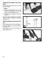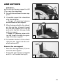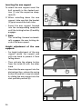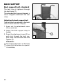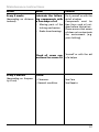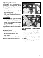
1
GB
OPERATING MANUAL
FOLDING WHEELCHAIR, MODEL
1.736
W e
m o v e
p e o p l e .
Contents
Introduction .................................................................................................. 6
Acceptance .................................................................................................... 7
Adaptation .................................................................................................... 7
Handling the wheelchair ............................................................................. 7
Specifications ........................................................................................................7
Use .........................................................................................................................8
Auxiliary drives .....................................................................................................8
Overview ....................................................................................................... 9
Driving behaviour ...................................................................................... 10
Safety information .............................................................................................10
Supplementary user/safety information...........................................................10
Brake ............................................................................................................ 12
Pressure brakes ...................................................................................................13
Locking the pressure brakes.........................................................................13
Releasing the pressure brakes......................................................................13
Drum brake for attendant ...........................................................................14
Leg supports ............................................................................................... 16
Calf strap ........................................................................................................16
Folding up the footplates ............................................................................17
Swivelling away the leg supports ................................................................17
Dismantling the leg supports .......................................................................18
Attaching the leg supports ..........................................................................18
Adjusting the height of the footplate ........................................................19
Angle adjustable footplates.........................................................................19
Continuous leg support .....................................................................................20
Folding up the footboard ............................................................................20
Folding down the foot board ......................................................................20
Height adjustment of the footboard ..........................................................20
Adjusting the height of the footboard .......................................................21
Angle adjustable footboards .......................................................................21
2
Height-adjustable leg support ..........................................................................22
Folding up the foot plates ...........................................................................22
Swivelling off and removal of the leg supports .........................................22
Attaching the leg supports ..........................................................................23
Height adjustment of the leg support ........................................................23
Adjusting the height of the footplate ........................................................24
Depth adjustment of the calf cushion.........................................................24
Armrests ...................................................................................................... 25
Remove the arm support..............................................................................25
Inserting the arm support ............................................................................26
Height adjustment of the arm supports .....................................................26
Mudguard.................................................................................................... 27
Adapting the clothes guard .........................................................................27
Seat .............................................................................................................. 28
Seat strap, standard ......................................................................................28
Seat cushion ........................................................................................................29
Adjusting the seat depth ..............................................................................29
Back support ............................................................................................... 30
Back support belt, standard ..............................................................................30
Adjusting the back support belt ..................................................................30
Angle adjustable back support .........................................................................31
Adjustment of the back support angle .......................................................31
Adjustment of the back tube bracket .........................................................31
Height adjustable back support ........................................................................32
Adjusting the back support height .............................................................32
Adjustable back ..................................................................................................33
Push handles ............................................................................................... 35
Height adjustable push handles........................................................................35
Height adjustment ........................................................................................35
Removing the push handles .........................................................................36
Inserting the push handles ...........................................................................36
Push handles with tube guidance .....................................................................37
Height adjustment ........................................................................................37
Adjusting the clamping strength .................................................................37
3
Wheels ......................................................................................................... 38
Drive wheels .......................................................................................................38
Quick release axle .........................................................................................38
Handrims .............................................................................................................39
Steering wheels ..................................................................................................39
Tyres .....................................................................................................................39
Support castors .......................................................................................... 40
Swivel-away support castors .............................................................................40
Swinging the support castors.......................................................................40
Insertable anti-tip castors ..................................................................................41
Removing/attaching the support castor......................................................41
Adjusting the support castor .......................................................................41
Correct support castors length.....................................................................41
Manoeuvre rollers ...................................................................................... 42
Shunting castors without brakes ......................................................................42
Seatbelt ....................................................................................................... 43
Fastening the seatbelt with buckle .............................................................43
Adjusting the belt length .............................................................................43
Therapy table .............................................................................................. 44
Mount the therapy table ..............................................................................44
Individual adjustment ............................................................................... 45
Seat height /Seat angle ......................................................................................45
Drive wheel position .....................................................................................46
Steering wheel position ...............................................................................46
Back support belt height ...................................................................................47
Folding/Transport ....................................................................................... 48
Folding/Unfolding ..............................................................................................48
Folding the wheelchair .................................................................................48
Carrying the wheelchair ...............................................................................49
Unfolding the wheelchair ............................................................................49
4
Loading and transportation ...................................................................... 50
Safety information ........................................................................................50
Transport in vehicles .....................................................................................50
Transport security ..........................................................................................50
Transport in handicapped transport automobile ............................................51
Maintenance ............................................................................................... 53
Cleaning and Care ..............................................................................................53
Upholstery and covers ..................................................................................53
Plastic parts ....................................................................................................53
Finish ..............................................................................................................53
Chassis ............................................................................................................54
Disinfection .........................................................................................................54
Reinstallment ......................................................................................................54
Maintenance ............................................................................................... 54
Maintenance instructions ..................................................................................55
Flat tyre ...............................................................................................................58
Tyre change ...................................................................................................58
Adjusting the brakes ..........................................................................................59
Fine adjustment of the pressure brakes ......................................................59
Repair ..................................................................................................................60
Customer service.................................................................................................60
Spare parts ..........................................................................................................60
Disposal ..........................................................................................................60
Inspection.................................................................................................... 61
List of annual maintenance work .....................................................................62
Inspection certificate through the dealer ........................................................63
Technical specifications ............................................................................. 65
Tools.....................................................................................................................69
Tightening torque for screwed connections ....................................................69
Meaning of the labels on the wheelchair ........................................................70
Notes............................................................................................................ 71
Guarantee ................................................................................................... 74
5
INTRODUCTION
We thank you for the confidence you
have placed in our company by choosing a wheelchair from this series.
This manual is to help you get accustomed to the handling of the wheelchair as well as to prevent accidents.
☞ Note:
Please note that the illustrated
equipment variants can deviate
from your model.
The model 1.736, fulfils the wish for
mobility and more independence by
way of a new styling of the proven
MEYRA technology.
With all equipment and their accessories the wheelchair offers die respective adaptation to your disability.
Like any other vehicle, a wheelchair is
a technical aid. It requires explanation,
a little care and holds dangers when
used improperly. The correct handling
must therefore be learned.
– We have therefore also listed
chapters with options that might
not be applicable for your vehicle.
!
Attention:
Read and observe the following
documentation belonging to the
wheelchair before first operation:
– this operating manual,
– the safety information < Mechanical wheelchairs >.
☞ Note:
Children should read the documentation belonging to the wheelchair
together with their parents respectively a supervisor or attendant before first use.
6
ACCEPTANCE
All products are checked for faults
in the factory and packed in special
boxes.
☞ Note:
☞ However, we request that you
check the vehicle for possible
transport damage immediately on
receipt – preferably in the presence
of the carrier.
☞ The packaging of the wheelchair
should be stored for a further
transport that might become necessary.
HANDLING THE WHEELCHAIR
Specifications
The wheelchair, model 1.736 was developed for adults and adolescents.
Three frames are available:
– short,
– medium,
– long.
The wheelchair solely serves to transport one person in the seat and not as
a hauling aid, transporters or similar.
ADJUSTMENT
Our specialist workshop supplies your
wheelchair ready for use and adjusted
to suit your special requirements.
☞ Note:
The tools required for adjustments
and maintenance is listed under
chapter < Technical Data >.
7
Use
Auxiliary drives
Through its constructive advantages
the wheelchair can universally be
implemented on hard surfaces and
therefore an allround-wheelchair:
Before attaching auxiliary drives the
following notes have to be considered:
– for indoors (e.g. apartment, day
care),
!
– outdoors (e.g. in parks),
– as a companion on tours (e.g. in a
bus or train).
The wheelchair offers manifold adjustment possibilities to individual vital statistics.
The wheelchair should be adapted
to your needs by a specialist dealer
before the first use. The adaptation
will take into account the driving experience, the physical limits of the
user and the main place of use of the
wheelchair.
!
8
Attention:
Always have adaptation and adjustment work carried out by a
specialist dealer.
Attention:
Attachment of auxiliary drives may
only be done on wheelchair models cleared for these.
☞ The list of wheelchair models
cleared for auxiliary drives can be
acquired at any authorised dealer.
OVERVIEW
The overview shows the most important components of the wheelchair.
1
2
9
3
4
5
13
8
7
6
Pos. Description
1
2
3
4
5
6
7
8
Back support
Arm support
Seat cushion
Leg support
Calf strap
Footrest
Steering wheel
Toggle
joint
Brake
12
11
10
Pos. Description
9
10
11
12
13
Push handle
Side element
Handrims
Drive wheel
Tilt aid
brake/Pressure
9
DRIVING
Alignment of the driving behaviour
and the personal abilities is to be carried out together with your specialist
dealer or therapist and is achieved after a short acquaintance period, test
drive.
!
Attention:
Drive with extreme caution during
these first trips!
• Observe the section < driving training > in the safety instructions <
Mechanical wheelchairs >!
Safety information
!
Attention:
Please follow all instructions in the
safety information < Mechanical
wheelchairs >.
• A directly opposed change of direction from backward motion without steering into a forward motion
with simultaneously inward swivelling steering wheels has the effect
of a full stop.
• Applying a safety belt prevents
falling out toward the front.
• In order to raise the backward tilting stability supporting wheels can
be mounted later on.
• When propelling the wheelchair
over the tyre there is a risk of injury in the area of the pressure brake.
10
Supplementary user/safety
information
• Clean, passive lighting is required
for driving in public traffic.
• Do not throw or drop parts belonging to the wheelchair! – Detachable parts like e.g. side elements
and drive wheels have to be used
properly To guarantee their function.
• Removable parts, e.g. side elements and drive wheels must be
checked for correct locking before
starting to drive. Drive wheels with
defective linchpin (quick-fit) axles
can detach from the wheelchair
during the drive.
• By adding on or removing accessories/components the dimensions
and weight of the wheelchair
change which can affect the driving behaviour.
• Never leave children/adolescents in
wheelchairs unsupervised.
• Always approach small obstacles,
e.g. steps or curbs, slowly and at a
right angle (90°) until the steering
wheels almost touch the obstacle.
Briefly stop the wheelchair and
then drive over the obstacle.
• Keep well clear of rail grooves, rails
and gully covers or similar sources
of danger. If not possible, cross such
obstacles at a right-angle (90°).
• Maintain a sufficient safety distance between the wheelchair and
drops, steps and obstacles. This
distance must allow enough time
to react and enough distance to
brake/turn.
• Tyres are made of a rubber mixture and can leave permanent or
difficult-to-remove marks on some
surfaces (e.g. plastic, wooden or
parquet flooring, carpets, mats).
• To prevent damages due to corrosion do not use ore store the
wheelchair in damp rooms.
Recommendation for driving in
twilight or darkness
• Avoid as far as possible driving on
roads or bicycle paths during darkness. Wear light-coloured clothing
that can be seen at a distance.
• Always reduce the speed before a
curve. A sharper curve requires a
lower speed. Never lean outwards
in a curve.
11
BRAKE
By locking the brakes the wheelchair
is to secured against unintentional
rolling off (parking brake).
1
The locking brake belongs to the most
important safety features of a wheelchair and is available as a pressure
brake (1).
!
Attention:
Please observe the maintenance
instructions as well as instructions
in the section < General safety instructions > and < Brakes > in the
safety instructions < Mechanical
wheelchairs >.
• The wheelchair loaded with the
user may not let itself be pushed in
with the brakes engaged.
• In order to prevent an unintentional curve while braking the wheelchair on slopes, both brakes are to
be activated simultaneously.
– Depending on the inclination of
the road a sideward tilting has to
be reckoned with.
• Do not support the body on the
lateral brake levers.
• The brake performance reduces
with
– tyre profile is worn
– tyre pressure is too low
– tyres are wet.
12
!
Attention:
Arrange an immediate repair of
the brakes by your specialist workshop if the braking performance
reduces.
• Do not park wheelchairs with PU
tyres with activated pressure or
butterfly-brakes. – Deformations in
the running surface may remain.
• If possible propel the wheelchair
over the handrims. – Perhaps danger of jamming in the area of the
brake!
Pressure Brake
A metered braking from driving
speed (operating brake) is possible
with the brake levers (1) of the pressure brakes.
Service brake
1
Press the two brake levers evenly only
slightly to the front, this brakes the
wheelchair in a metered fashion.
Locking the pressure brakes
To secure the wheelchair against any
unintentional rolling, press both brake
levers forward all the way (1).
2
☞ Note:
It should not be possible to push
the wheelchair forward when both
brakes are locked.
Releasing the pressure brakes
Pull both brake levers back all the way
(2).
13
Drum brake for attendant
A metered braking from driving speed
(operating brake) is possible with the
brake levers of the drum brakes.
The wheelchair is also to be secured
against unintentionally rolling away
(parking brake) by engaging these
brakes.
1
Locking the drum brakes
Pull both brake levers evenly to secure
the wheelchair against unintentional
rolling away.
Press the latch (1) forward.
Release the brake lever. – Depending
on the adjustment the latch engages
in the first (A) or second (B) locking
position and activates the brake.
☞ Note:
☞ The wheelchair loaded with the
user may not let itself be pushed in
with the brakes engaged.
☞ If the third locking position (C) is
required to activate the brake, it
must be readjusted by a specialist
workshop.
14
C
B
A
Loosen the drum brakes
Pull both brake levers (1) until the
latches (2) automatically jump out of
the lock.
Release both brake levers. – The parking brakes are release and the wheelchair ready to go.
!
Attention:
For driving the front and rear brake
levers must be disengaged.
2
1
☞ Note:
The braking effect depends upon:
– the condition of the tyres,
– the condition and attachment of
the brakes,
– the brake lever adjustment,
– the road condition.
!
Attention:
The braking effect decreases with:
– worn brake pads,
– loose brake lever,
– defective drum brakes.
•
If the effect of the brake lessens
immediately have them readjusted
in a specialist workshop.
15
LEG SUPPORTS
!•
Attention:
Do not use the leg supports to lift
or carry the wheelchair.
1
The parking brakes are to be engaged before all assembly work. –
This prevents the wheelchair from
rolling away accidentally.
Calf strap
The calf strap (1) prevents the feet
from sliding off of the footplates.
– It is guided around special ligament (2) and adjusted in length
with a velcro fastener.
Removal of the calf belt is achieved by
opening the velcro straps.
!
16
Attention:
Never drive without leg strap (except when shuffling)! – The leg
strap is omitted for height adjustable leg supports and is replaced
by the leg padding.
2
Folding up the footplates
The footplates are to be folded up
for entry into, exiting the wheelchair
or scuttling (forward motion of the
wheelchair with the feet) (1).
Turning the leg supports to the
side
For easy transfer out of/into the
wheelchair as well as driving closer to
a closet, bed or bathtub the leg supports can be swivelled away toward
the in-/outside (3) and (4).
1
– Therefore pull or press the respective locking lever (2) and swivel the
corresponding leg support inward/
outward.
2
☞ Note:
For this the calf strap is to be loosened on one side.
!
•
Attention:
Swivelled-away leg stump supports
are automatically unlocked and
can easily fall off. Note this when
handling (e.g. transport).
When swivelling them back make
sure that the leg support audibly
locks into place.
☞ Note:
3
After swivelling the leg support inward again do not forget to check
the corresponding locking device.
Afterwards replace the calf strap.
4
17
Removing the leg supports
For easy transfer into and out of the
wheelchair as well as a reduced wheelchair length (important for transport)
the leg support can be removed (1).
☞ Note:
Before swivelling the leg support
loosen or remove the calf belt on
one side.
1
– Remove both feet from the footplates.
– Pull or press the locking lever backward (2).
– Swivel the leg support sideways
and take them off toward the top
(1).
Attaching the leg supports
With the leg support in a swivelledaside position, hang it in and then
swivel it to the front until the locking
device audibly latches.
☞ Note:
After swivelling the leg support inward again do not forget to check
the corresponding locking device.
Afterwards replace the calf strap.
18
2
Adjusting the height of the footplate
Remove the clamping screw (1) to adjust the height.
1
Telescope the foot plate to the desired height and then secure it with
the clamping screw.
Angle adjustable footplates
After loosening the clamping screw (2)
pull out the dovetail connection and
adjust the angle of the footplates.
☞ The setting screw (3) serves to horizontally correct the angle of the
footplates.
Afterwards retighten the clamping
screw.
– In doing so the teeth of the angle
adjustment must join again
2
3
19
Continuous leg support
The footboard of the continuous leg
support (1) can be folded up to the
side.
Folding up the foot board
For an unobstructed foot area, fold
up the left side of the foot board to
the right as far as it will go (2).
1
Folding down the foot board
Fold down the left side of the foot
board until it rests on the foot board
holder (3).
Height adjustment of the footboard
2
Loosen the clamping screw (4) to adjust the height.
Telescope the foot plate to the desired
height and then retighten the screw.
☞ Note:
The maximum extension is indicated by a marking (6) on the tube
(5).
3
4
6
5
20
Adjusting the height of the footboard
1
Loosen the clamping screw (1) to adjust the height.
Telescope the footboard to the desired height and then retighten the
screw.
Angle adjustable footboards
After loosening the clamping screw (2)
pull out the dovetail connection and
adjust the angle of the footplates.
Afterwards retighten the clamping
screw.
– In doing so the teeth of the angle
adjustment must join again
2
21
Height-adjustable leg support
Folding up the footplates
For entry and exiting the footplates
(1) are to be folded up and the calf
cushions (2) swivelled outward in driving direction.
2
1
Swivelling off and removal of the
leg supports
For easy transfer out of/into the
wheelchair as well as driving closer to
a closet, bed or bathtub the leg supports can be swivelled outward and
removed.
3
☞ Note:
☞ Operate parking brakes. – This
prevents accidental rolling of the
wheelchair (see section < Brakes
>).
– Swivel the calf cushions in driving
direction outward.
– Remove both feet from the footplates.
– Pull or press the respective locking
lever (3) backward and swivel the
respective leg support outward
and remove it to the top if necessary.
!
•
22
Attention:
Swivelled-away leg stump supports
are automatically unlocked and
can easily fall off. Note this when
handling (e.g. transport).
When swivelling them back make
sure that the leg support audibly
locks into place.
☞ Note:
After swivelling the leg support inward again do not forget to check
the corresponding locking device.
– Afterwards swivel the calf cushion
inward again.
Attaching the leg supports
With the leg support in a swivelledaside position, hang it in and then
swivel it to the front until the locking
device audibly latches.
☞ Note:
After swivelling the leg support inward again do not forget to check
the corresponding locking device.
1
– Afterwards swivel the calf cushion
inward again.
Height adjustment of the leg support
When seated in the wheelchair, ask a
carer to raise the leg support to the
desired level. The length adjustment
is given through the turning point at
the height of the knee joint.
To lower the leg support, remove the
load momentarily from the support
by raising the lower thigh (ask an attendant if necessary), and loosen the
clamping lever (1).
Attention:
Never put the free hand into the
adjustment mechanism while adjusting the height adjustable leg
support. – Danger of crushing!
The leg support can now be moved
slowly downwards.
!
•
Operate parking brakes. – This
prevents accidental rolling of the
wheelchair (see section < Brakes
>).
•
Do not let the leg support drop
on its own weight. – Danger of
squashing!
After the adjustment retighten the
clamping lever (1).
1. First secure the leg support with
one hand against folding down,
and then loosen the clamping lever (1).
2. Have the leg support lifted to the
desired level by an attendant and
retighten the clamping lever (1).
23
Adjusting the height of the footplate
Loosen the clamping screw (1) to adjust the height.
☞ Note:
☞ Loosen the clamping screw (1) so
1
far that no damage to the coating
occurs during the adjustment.
☞ Observe the maximum extension
mark (2).
Telescope the foot plate to the desired
height and then retighten the clamping screw (1).
Depth adjustment of the calf cushion
Depth adjustment of the calf plates is
achieved after removing the respective screws (3).
2
Reassemble the screws (3) after the
depth adjustment.
3
24
ARM SUPPORTS
!•
Attention:
Do not use the arm supports to lift
or carry the wheelchair.
1
Do not drive without the arm supports!
•
If possible propel the wheelchair
over the handrims.
– Danger of jamming between
drive wheel and arm support!
•
When being pushed by the attendant the user has to keep his hands
on the arm supports or in his lap
and not at the sides between body
and arm support.
– Danger of jamming when sticking the fingers through the openings of the arm support!
2
☞ To transfer into/out of the wheelchair the arm support can be swivelled backward (2).
Remove the arm support
– Press the locking button (1) to remove the arm support.
– Swivel the arm support upward (2)
and lift it off toward the top(3).
3
25
Inserting the arm support
To attach the arm support insert the
bolt currently in the slanted position (1) into the respective receptacle (2).
3
1
☞ When swivelling down the arm
2
support, take care that the bracket
(3) grips around the back tube.
– Swivel the arm support forward
into the corresponding receptacle
until the locking button (4) audibly
engages.
4
☞ Note:
The swivelling forward automatically engages the rear locking device of the arm support.
Height adjustment of the arm
supports
– For height adjustment of the arm
support secure the support pad
with one hand to prevent it from
falling down.
– Then activate the release button
from the inside (5) with the other
hand.
– Now slide the arm support into the
desired position, release the spring
button (5) and let it snap into place
by sliding the arm support into the
next possible position (6).
5
6
26
CLOTHES GUARD
X
4
The distance (X) to the clothes guard
running parallel to the wheel diameter (1) is to be aligned to the selected
wheel position.
!
Attention:
The distance X between the driving
wheel and the mudguard should
be as small as possible (approx. 1
cm). – Danger of crushing!
Adapting the clothes guard
– Remove the corresponding drive
wheel.
☞ Hereto observe chapter < Drive
wheels >.
2
– Dismantle the screwed connections
(2).
– Position the clothes guard (1) to
the equalising wheel circumference.
– Reassemble the screwed connections (2).
3
☞ Note:
☞ After removing the clothes guard
the attachment clamp (3) can be
dismantled, turned by 180° and
be reassembled. By this further attachment positions are possible for
the clothes guard.
☞ After alignment to the wheel circumference check the functions of
the arm support.
27
SEAT
Seat strap, standard
1
The seat strap (1) is tensed through
the seat tubes and can be bent upward in the middle for folding (2).
☞ Therefore observe chapter < Folding/Unfolding >.
2
28
Seat cushion
The seat cushion is aligned to the
centre and placed from front to back
onto the velcro straps at the sides of
the adjustable seat strap (1).
The seat cushion can be removed toward the top for folding (2). – Velcro
fastener.
1
Adjusting the seat depth
The seat depth can be continuously
adjusted by max. 3 cm by sliding the
front adjustable seat strap (3).
☞ Note:
For this slide the two velcro seat
straps parallel on both sides.
Afterwards realign the seat cushion
and place it in the centre (4). – Velcro
fastener.
2
3
4
29
BACK SUPPORT
Back support belt, standard
The back strap is tightened through
the back tubes (1).
The extended back support element is
velcro strapped underneath the seat
strap.
1
Adjusting the back support belt
Two holes each are already in the back
tubes t attach the back strap (2).
1. Screw out the attachment screw
(3) on each side.
2. Adjust the back support strap in
height.
3. Screw the attachment screw (3) on
each side through the back support strap into the back tube and
tighten (2).
!
30
Attention:
The height adjustment of the back
strap is only to be done in a specialist workshop.
3
2
Angle adjustable back support
The angle adjustable back support (1)
can be adjusted in angle by +/- 10° in
5°-steps.
Adjustment of the back support
angle
– Therefor remove the arm supports
(2).
1
☞ Observe chapter < Arm support >.
– Then screw out the attachment
screws (3) on both sides (2).
3
– Then adjust the back support tubes
parallel to the desired back angle.
– Then remount the screws on both
sides (3) and adjust the back tube
brackets on both sides.
2
Adjustment of the back tube
bracket
4
– First loosen the clamping screw
(4) of the back support bracket of
each arm support and slide it backward (5).
– Then reinsert the arm supports (5).
– Then slide the back support bracket of each arm support into the respective back tube (6) and tighten
the clamping screw (4).
5
4
6
31
Height adjustable back support
The height adjustable back support
(1) is continuously adjustable in height
(2).
Adjusting
height
the
back
support
– Therefor remove the back cushion
(3). – Velcro fastener.
1
☞ Observe chapter < Adjustable back
support >.
– Then loosen the clamping screws
(4) on both sides and adjust the
back tubes parallel according to
the cm scale at the side to the same
height (5).
– Then retighten the attachment
screws (4) on both sides.
2
☞ The telescopic tubes are secured
by a spring wire within the tube
to prevent them from being pulled
out completely.
☞ If the spring wire is defective the
4
telescopic tubes can be adjusted to
max. 15 cm according to the scale
(5).
☞ Defective spring wires can be re-
3
placed in the specialist workshop.
5
32
4
Adjustable back
The adjustable back is adjustable
through a velcro strap, the so called
spanning straps (1).
The cushion (2) is placed over it and
attached with the velcro strap.
1
2
Adjusting the adjustable back
☞ Note:
☞ The fitting of the adjustable back
(1) is best carried out with the user
sitting in the wheelchair and the
seat angle is set at 0°.
☞ Adjustment is carried out from the
bottom to the top.
☞ The lower part of the adjustable
back should remain slightly loose
so that it adapts to the buttocks
when bending forward.
!
2
Attention:
The overlapping of the Velcro fastener has to be at least 10 cm!
1. Pull off the rear part of the cushion.
2. Span the spanning straps tightly
over the small of the back and
lumbar spine in order to give maximum support.
3. Adjust the remaining straps to the
form of the back.
4. Afterwards loosen the front part
of the cushion and align it with the
spanning straps.
☞ In doing so the user should lean
forward. If necessary ask an aid to
help out!
33
Place the back cushion
The back cushion (1) is to be folded
over in the centre between the two
horizontal seams 180° around the upper spanning straps (2), (3). – This creates a soft upper edge.
1
2
☞ Note:
When the user leans against the
front cushion again, pay attention
that:
3
☞ The pressure of the back must be
spread evenly throughout the back
cushion.
☞ A complete hand should fit in between the cushion and back at the
upper edge of the back cushion.
☞ The head of the user must be held
at balance by the back cushion.
4
The extended parts of the back support are fastened to the top or bottom seat surface depending on the
adjusted back support height (4).
☞ Note:
With an adjusted back support
height from 9 cm according to the
scale on the side, the straps of the
back cushion are led around the
back tubes (5).
34
5
PUSH HANDLES
Height adjustable push handles
The height adjustable push handles
(1) are attached to the back support
with a clamping jig each (2) and can
be adjusted to the requirements of
the attendant.
1
The push handles are continuously
height adjustable, swivelling in steps
of 30° and secured against being
pulled out.
☞ Note:
Further varieties of push handles
are optionally available at you specialist dealer.
2
Height adjustment
– Loosen the clamping screw with
the clamping levers (2) so far that
the respective push handle can be
adjusted into the desired position.
– Lift the push handle to the desired
height.
– Retighten the clamping screw with
the clamping levers (2).
Special features of the clamping
lever
The clamping lever (2) can be turned
into an operation position that is comfortable for you.
– For this pull the lever outward, until the teething is released.
– After turning the lever let the
teething engage again.
35
Removing the push handles
Loosen the clamping screw with the
clamping lever (3) and pull the according push handle up as far as it
will go.
Press the respective spring button (1)
inward and pull the push handle out
of the clamping device (2).
Inserting the push handles
Press down the spring button (1) and
insert the push handle from the top
into the respective clamping device
(2).
Push the push handle through the
clamping device (2) and retighten the
clamping screws with the clamping lever in the desired position (3).
36
4
5
3
Push handles with tube
guidance
The push handles (1) are guided
swivel-proof inside the back tube and
steplessly height by up to 10 cm.
2
Height adjustment
– First hold onto the push handle
that is to be adjusted then swivel
the corresponding clamping lever
(2) with the other hand into the
horizontal position.
1
– Then adjust the push handle to the
desired height and clamp it tight
(3).
– For this swivel the clamping lever
downward (1).
!
Attention:
After each adjustment the secure
fit of the push handles is to be
checked with a pull-/push test!
3
☞ Note:
With the clamping lever swivelled
down, the respective push handle
may not let itself be moved.
Adjusting the clamping effect
The clamping effect can be adjusted
with the screw (4).
4
5
– For the adjustment swivel the
clamping lever up (5).
– To increase the clamping effect
turn the screw (4) in by about
one quarter rotation. – Check the
clamping function.
37
WHEELS
Drive wheels
The drive wheels are on a quick release axle.
☞ No person may be seated in the
1
wheelchair during assembly or removal. The wheelchair must stand
on a level and firm surface. Before
starting the disassembly work,
support the frame to prevent the
wheelchair from tipping over and
secure it to prevent an unwanted
movement or tipping over.
Quick release axle
The driving wheels can be removed
and reassembled without any tools.
– For this first unlock the quick release axle by pressing the spring
button (1), then pull the drive
wheel off toward the outside.
To replace the drive wheels unlock the
respective quick release axle by pressing the spring button (1) and press it
as far as possible into the axle receptacle.
Attention:
After inserting the drive wheel the
locking button must stick a couple
of millimetres out of the wheel
nut.
☞ The locking bolt is to be kept clean.
☞ Note:
☞ After each assembly the locking
☞ If the drive wheels has too much
!
device is to be checked with sideward pulling/pressing on the drive
wheels!
38
A functional fault may occur in the
case of contamination due to sand
or earth or in the event of freezing
of moist cold air.
sideward lag or the axle does not
engage, have it maintained immediately by the specialist dealer.
Handrims
All handrims are designed for a 15
mm to 25 mm (standard adjustment)
(1) distance to the drive wheel.
!
•
Attention:
Replacement of handrims or modification of handrim distances
should always be carried out by
your specialist workshop.
1
Observe the safety instructions <
Mechanical wheelchairs >, chapter
< Handrims >!
Steering wheels
The steering wheels can be exchanged
without difficulty.
For removal of the wheels the screw
axle (2) has to be disassembled.
2
Tyres
Air tyres:
The air pressure of the tyres is noted
on both sides of the wheels or can be
viewed in the < Technical data >.
Puncture proof tyres:
The puncture proof tyre can be recognised through the missing air pressure
valve.
39
SUPPORT WHEELS
The support castors serve to increase
the tilting stability.
!
Attention:
In certain situation the support
castors do not provide sufficient
protection against falling over.
1
1
Therefore, do not:
▲ Leaning the upper body far back.
▲ When the wheelchair starts suddenly, especially when driving uphill.
▲ Driving over steps, e.g. curbs or
stairs.
– Danger of falling over forwards.
☞ Note:
☞ Observe the safety and general
handling instructions < Mechanical
wheelchairs >!
Swivel-away support castors
The swivelling support castors (1) can
be swung inward under the seat (2).
☞ Swivelling of the support castors
can be done by an attendant or
aid.
Swinging the support castors
First press the support castors down
out of the lock then swivel them under the seat (2), or toward the back
(1) until the respective lock engages
automatically.
☞ Note:
This function can be performed
with the foot.
40
2
Stick-in support wheels
Removing/attaching the support
castor
To remove / insert the support castors
press down the respective spring button (1).
1
When replacing the support castors
slide them in until the spring button
(1) automatically snaps into place.
2
☞ Note:
The spring button must engage visibly and audibly. – Check the function!
Adjusting the support castor
Press the spring button to adjust the
support castor (2), the reposition the
support castor accordingly until the
spring button automatically locks into
the next position.
☞ Note:
The spring button must engage visibly and audibly. – Check the function!
Correct support castors length
The support castors must reach further
out than the drive wheels in order to
achieve a sufficient support function.
!
Attention:
For sufficient tilting stability both
support castors are to be positioned evenly.
• Have the function checked by the
specialist dealer after each change
to the seat height and wheel size!
☞ Note:
Therefore observe the safety instructions < Mechanical wheelchairs > chapter < Inclinations,
overcoming obstacles > as well as <
Driving on elevators, lifts and escalators >!
41
MANOEUVRE ROLLERS
For driving through tight passages
(e.g. in trains) the wheelchair can be
pushed over the shunting castors (1)
without drive wheels by an attendant.
By removing the drive wheels the
wheelchair can be used as a transit
chair when combined with the shunting castors.
Shunting castors without
brakes
!
Attention:
The transit wheelchair may only be
parked under the supervision of an
attendant! – No braking function
possible!
– Danger of accidents through uncontrolled rolling motions!
☞ Note:
When using the shunting castors
the attendant is responsible for
the safety of the person sitting in
the wheelchair.
☞ Observe the safety information <
Mechanical wheelchairs >!
Height adjustment
After changing the seat height as
well as after changing the size of the
wheels, the shunting castors may have
to be adjusted in height again.
☞ The correct height setting is to be
checked by the specialist dealer
and readjusted if necessary.
42
1
SEAT BELT
3
The seatbelt serves to strap in a person sitting in the wheelchair.
2
– Additional stabilisation of the sitting position.
– Prevents the user from falling forwards out of the wheelchair.
4
– Continuous adjustment to suit the
user’s needs.
The seatbelt is screwed from the back
onto the respective back support
tube.
☞ Note:
The retrospective assembly of a retaining strap is only to be carried
out by a specialist workshop!
!
Attention:
The retaining strap is not part of
the retaining system for the wheelchair and/or user during transport
in a handicapped vehicle.
Fastening the seatbelt with buckle
Adjustment of belt length
– Pull both belt halves to the front
☞ Note:
and slide the catch halves together
so that they latch together. Then
carry out a pull test.
To open the seatbelt the red locking
button (2) is pressed down.
!
The seatbelt should not be pulled
too tight.
The length of the seatbelt can be
changed by sliding the buckle (3) and
/ or pulling the end of the strap (4).
Attention:
Make sure that no objects are
trapped between belt and the
body! – Thus you avoid painful
pressure points
43
THERAPY TABLE
!
•
Attention:
Place, adjust and reposition or remove the therapy table only after
activating the brakes.
Sharp objects (e.g. watches, rings,
knives or belt buckles) as well as
coarse dust can cause unattractive
brush marks in the surface of the
therapy table.
•
Do not use aggressive or granular
cleaning agents to clean the therapy table!
•
Do not place any hot objects onto
the therapy table!
•
Do not drive with the therapy table attached when there are loose
objects or containers with fluids on
it!
•
Do not use the therapy table as
handle for carrying the wheelchair!
Mount the therapy table
The therapy table is pushed from the
front over the arm support cushions
(1).
!
44
Attention:
For a safe stability of the inserted
therapy table only arm supports
with long arm support cushions
should be applied (1).
1
INDIVIDUAL ADJUSTMENT
2
The adjustment possibility offers a:
1
– individual adaptation of the seat
height to your lower leg length,
– user compatible seat angle,
– increased tilting stability.
!
•
Attention:
Individual adjustments like repositioning the drive and steering
wheels are only to be carried out
by your specialist dealer.
Every new adaptation can change
the driving behaviour.
Seat height /Seat angle
3
The user compatible adjustment of the
seat height and –angle is done by:
– Repositioning the axle receptacle
(1) within the vario-block (2).
– Repositioning the vario-block (2).
– Changing the size of the steering
wheel.
– Assembly of the castor stem (3)
into a further position.
4
– Assembly of the steering axle (4)
into further positions.
45
Driving wheel position
The positions of the drive wheel depends on:
2
– the desired seat height,
1
– the seat angle,
– the steering wheel.
!
Attention:
If the vario-block (2) with the axle
receptacle (1) is repositioned horizontally, the wheel base is changed
and thus also the driving behaviour.
•
With each displacement of the axle
receptacle (1) toward the front the
danger of tilting increases!
•
Therefore only drive with support
castors to increase the tilting stability!
Steering wheel position
The necessary position of the steering
wheel is predetermined by the specification of the respective drive wheel
position.
☞ Note:
The castor bushing (3) has to be
readjusted after every position
change of the drive wheels.
46
3
Back support belt height
The back strap height can be adjusted
into a further attachment position by
repositioning the back strap (1).
– Therefore first remove the attachment screws (2) of the back strap.
1
– Afterwards reposition the back
strap and retighten with the attachment screws (2).
2
47
FOLDING/TRANSPORT
Folding/Unfolding
Folding the wheelchair
The Lightweight Wheelchair can be
folded without tools in few steps, (1).
Remove the seat cushion, if applicable.
If necessary remove the calf strap.
Remove the leg supports or fold up
both footplates, see section < Leg supports >.
If available separate the back stiffening bracket, therefore view chapter <
Back stiffening bracket >.
Pull the back support extension off toward the bottom, view chapter < Back
support belt >.
Bend the back belt to the rear.
Pull the seat belt upward in the front
and back center (1).
48
1
Carrying the wheelchair
Your wheelchair can be carried without difficulty when folded.
Fold the wheelchair, therefore view
chapter < Folding the wheelchair >.
From the front push one lower arm
under the upward folded seat belt.
Place other hand underneath the rear
seat fold for support.
2
Lift the wheelchair to horizontal position.
Unfolding the wheelchair
Tip the wheelchair slightly to one side
in order to make the unfolding easier.
At the side resting on the floor, press
the seat tube down to the end stop
(2).
☞ Note:
☞ You may need to press down both
seat tubes with the hands in order
to do this.
☞ Observe that the seat tube sits securely on the support surface.
49
LOADING AND TRANSPORTATION
Safety information
▲ For the transport in vehicles, you
must leave the wheelchair and sit
in a suitable seat in the vehicle. The
transportation of persons in wheelchairs is prohibited. – The wheelchair is not designed to withstand
the forces which are generated in
accidents, which exposes the user
to considerable risks.
Transport in vehicles
Transport security
Carry out the following steps when
the wheelchair is located in the transport vehicle:
– Operate parking brakes.
– Any parts that have been dismantled from the wheelchair should be
stored safely in a protected place.
– Remove bags, walking sticks and
other items not belonging to the
wheelchair and stow these safely.
– Secure the wheelchair by way of
elastic straps.
The following items may be necessary
due to lack of space for the transport
in vehicles.
Only fasten the elasticised belts to
parts of the car envisaged for this purpose and to the frame tubes of the
wheelchair!
▲ Remove the leg supports.
▲ Do not use the side elements, foot-
▲ Removing the head support.
▲ Detach drive wheels.
The parts detached for the transport
must be carefully stowed and carefully attached again before the next
journey!
☞ Note:
☞ During reassembly, ensure that
each part is correctly installed and
securely fastened. Check that components are correctly positioned.
☞ Check the correct seating of the
components.
50
plates or push bar to rig the wheelchair. Only use permitted fastening
material.
☞ Suitable fixing points can usually
be found in the car and in the vehicle operating manual.
☞ Before transporting the wheelchair,
ask your car dealer how to secure it
without risk to the existing fixtures
or other safety fittings!
Transport in handicapped
transport automobile
Should transport in an electric vehicle
be inevitable, it must feature a retaining system according to DIN 75078
part 2. Should you require a retaining system please contact a specialist
dealer.
The transport vehicle (handicapped
transport vehicle) needs to have the
equipment for transporting wheelchairs according to DIN 75078 Part 1.
This norm describes a „power-knotsystem“. With this system the unit
wheelchair and user is secured in a
handicapped transport vehicle. The
system is divided into two components:
The lap seat belt must be length adjustable and fit with a latch to connect with the receptacle of the vehicle
shoulder strap.
The standardised latches are on the
one side connected to the wheelchair
and on the other hand with the spanning loops or hole grid of permitted
strap reactors that are countersunk
into the floor of the vehicle according
to DIN 75078 part 1.
The restraint system only offers sufficient safety in regular traffic situations (sharp braking manoeuvres and
similar) but not during collisions outside of the normative testing values.
Especially not during a boot crash.
☞ Note:
The headrest on the wheelchair
serves as a support for the posture
of the head, not as a transport security. Therefore a handicapped
transport vehicle-firm head support is necessary!
– Personal retaining system (PRS)
– Wheelchair
retaining
system
(WRS)
The retaining system should fulfil the
following technical requirements:
– Strap course of the PRS in the area
of the pelvis and shoulder with as
little as possible risk of injuries of
inner organs.
– Simple, clear and quick operation
through the driving service and
good accessibility within the transport vehicle.
!
Attention:
Angle adjustable back supports are
to be set vertically.
• Tipped seats are to be set horizontal.
• Height adjustable seats are to be
put into the basic position
The power-knot-system is a firm, retrofittable element on the wheelchair,
on which the PRS and WRS merge.
These requirements are fulfilled by a
4-point-system that consists of 2 front
standardised latches for spanning reactor and 2 rear standardised latches
for spanning retractor and lap seat
belt.
51
Product liability instructions
☞ Transport in the wheelchair with a
handicapped transport automobile
(BTW) is done at own risk!
☞ We do not accept liability for dam-
Special safety instructions for
shell seats
!
ages or other possessions that occurred through the transport in a
handicapped transport automobile.
•
Safety information
☞ When transporting a person, make
sure that there are no objects
jammed underneath the straps!
– Thus you avoid painful pressure
points
☞ As far as possible use a vehicle-installed seat during transportation.
☞ Only transport the wheelchair in
driving direction.
☞ The driver, resp. the attendant is
responsible for the professional
securing of the wheelchair in the
BTW.
☞ For professional transport in a BTW
the wheelchair and person have to
be placed on the therefore determined space and secured with the
corresponding securing system.
☞ Loose object are to be stored securely.
52
Attention:
The power knot on children's seats
and generally for shell provisions
(incl. RECARO-system) serves solely
for securing the wheelchair inside
the handicapped transport vehicle!
Only use seats that have been
cleared by the manufacturer for
the transport in a handicapped vehicle.
☞ It must be guaranteed that hip- and
shoulder strap lie tight around the
user. Otherwise the person might
slide out underneath the belt in
case of an emergency.
☞ Securing of the person must be
achieved with a strap that is integrated into the seat or shell.
SERVICE
Plastic parts
Cleaning and maintenance
The arm supports and parts are made
of high-quality plastic.
☞ Note:
☞ Do not clean the wheelchair with a
☞ Only clean the plastic parts with
warm water and neutral detergent
or soft soap.
high-pressure cleaner!
☞ For care you should use silicon free
cleansing or care agents on a warm
water basis such as the leather care
emulsion from Sonax. – In doing so
the manufacturers instructions are
to be observed.
☞ Do not use aggressive cleaning
agents e.g. solvents, or hard brushes etc.
!
Attention:
The arm supports are made of polystyrene and are affected by nonionic tensides as well as through
solvents and especially alcohol.
☞ When using commercial plastic
cleansers the manufacturers application instructions are to be observed.
Upholstery and covers
Finish
Clean the upholstery and covers with
warm water and hand wash lotion.
Spots can be removed with a sponge
or a soft brush.
The high quality finish ensures an
optimum of protection against corrosion.
☞ Note:
☞ For paint and chrome care the
Wash off persistent dirt with commercial fine detergent.
commercially
available
brand
name paint and chrome cleansers
are recommendable.
☞ Do not soak! Do not machine
☞ Should the coating be damaged
wash!
Follow-up with clean water and allow
to dry.
with scratches or similar, these areas can be touched up with our
paint pen available at the specialist dealer.
53
Chassis
Reinstallment
The chassis and wheels can be cleaned
damp with a mild detergent. Afterwards dry off well.
Before reimplementation the wheelchair is to undergo a complete inspection.
☞ Note:
☞ Note:
Check the chassis for corrosion
damages as well as other damages.
Occasional application of a light cover of oil to all moving parts (see also
Maintenance Instructions) will ensure
that your wheelchair will give you
many years of service.
Disinfection
If the product is used by more than
one person (for example in a care centre), the use of a commercial disinfectant is mandatory.
For hand disinfection of the product
we recommend Incidin plus in 0.25 to
0.5% concentrations or an equivalent
disinfectant.
☞ In doing so the manufacturers instructions are to be observed.
☞ Note:
Before disinfection the upholstery
and handles are to be cleaned.
54
The hygienic measures required
for reimplementation are to be
carried out in correspondence with
the validated hygienic plan.
MAINTENANCE
The following maintenance Instruction gives you a guide for carrying out
the maintenance work.
☞ They do not give information
about the actual extent of work
required on the vehicle.
Maintenance instructions
WHEN
WHAT
Remark
Before starting out
Test brakes for faultless operation
Carry out test yourself or
with a helper.
Activate brake lever to
the limit. The locked
wheels should not be
able to turn under operating conditions. If they
can still turn, the brakes
must be repaired by a
specialist workshop.
Check brake for wear
Move brake lever to
the side
Carry out tests yourself
or have a helper do it.
If you notice any increasing slackness on
the brake lever take
the wheelchair to your
specialist workshop immediately for repairs.
– Danger of accidents!
Check all screwed on
parts for secure fit
The following is to be
checked with great care:
– Attachment of the
back- and seat profiles
at the side frame,
– attachment of the
footplate to the side
frame,
– attachment of the
stabiliser rod underneath the seat surface.
55
Maintenance instructions
WHEN
WHAT
Remark
Before starting out
Check air pressure of
the tyres
Do it yourself or with the
aid of a helper.
Use a tyre pressure tester
or, if not available, the
'thumb press' method or
similar (view Safety instructions < Mechanical
wheelchairs > chapter <
Brakes >).
Standard tyres:
4 bar = 56 psi
High-pressure tyres:
8.0 bar = 116 psi
56
Check tyre profile
Carry out visual check
yourself.
If the tyre profile is worn
down or if the tyre is
damaged, consult a specialist workshop for repairs.
Check the back tubes
and frame tubes for
damages.
Carry out tests yourself
or have a helper do it.
If deformations or cracks
occur in the welding
seams, contact a specialist workshop immediately for repairs.
– Danger of accidents!
Maintenance instructions
WHEN
WHAT
Remark
Every 8 weeks
(depending on distance
covered)
Lubricate the following components with
a few drops of oil
Do it yourself or with the
aid of a helper.
Components must be
free from used oil residues before lubrication.
Please ensure that excess
oil does not contaminate
the environment (e.g.
your clothing)
– Moving parts of the
locking mechanism.
– Brake lever bearings.
Check all screw connections for secure fit
Every 6 months
(depending on frequency of use)
Yourself or with the aid
of a helper
Check:
– Cleanness.
See Care
– General condition.
See Repairs.
57
Flat tyre
If a flat tyre occurs to the air filled
tyres due to puncture by sharp objects
such as nails, screws, glass splinters,
etc. the damage should be eliminated
by repairing (mending the inner tube)
or replacing the inner tube.
!
Attention:
Sitting in the wheelchair during a
wheel change is not permitted. The
wheelchair must stand on a level
and firm surface. Before starting
the disassembly work, support the
frame to prevent the wheelchair
from tipping over and secure it to
prevent an unwanted movement
or tipping over.
Changing the tyres
☞ Note:
!
Always change tyres in pairs. – Differently worn tyres can impair the
straight-on travel of the wheelchair.
Attention:
Before tyre repair, open the pneumatic valve and vent any remaining
compressed air in the inner tube.
☞ Note:
The air pressure for the tyres is
shown on both sides of the tyre
and in the < Technical data > section.
58
1
Tyre change of the drive wheels
!
Attention:
Ensure that the tyre cover is always
removed and reinstalled with the
appropriate tyre levers (bicycle accessories).
Never use screw drivers or other
pointed /sharp edged objects as levers!
Tyre change
wheels
of
the
steering
Before replacement or repair the
steering wheel axle (1) is to be disassembled.
☞ Note:
Take note of the arrangement of
all sleeves and washers used.
Adjusting the brakes
According to the < Maintenance instructions > the brakes are to be
checked for function after each repositioning of the drive wheels and readjusted if necessary.
– Loosen the clamping screws (1) of
one pressure brake.
1
– Afterwards Preadjust the respective brake by repositioning it accordingly.
Pressure brake:
– For this slide the brake bolt of the
inactivated brake (2) to approx. 5
mm - 10 mm in front of the drive
wheel and align it at a right angle
to the drive wheel.
2
– Retighten the clamping screws (1).
Adjust opposite pressure brakes as described.
Equally adjust both pressure brakes,
taking into account
– tread of the drive wheels,
– air pressure of the tyres and
– user weight.
adjust evenly. – Danger of accidents
caused by one sided braking effect!
Fine adjustment of the pressure
brakes
– Slacken the clamping screws (1).
– Fine tuning is achieved by slight repositioning of the respective pressure brake.
– Retighten the clamping screws (1).
☞ Note:
Inspect function and accurate fit of
the pressure brakes (2).
59
Repair
To conduct repair or maintenance
work trustfully contact a specialist
workshop. It is briefed in carrying out
the work and has educated personnel.
Customer Service
Please contact a specialist dealer if
you have any questions or need help.
A specialist dealer has been trained
by us in our factory according to our
guidelines and can give advice and
carry out maintenance, servicing and
repairs.
Spare parts
Spare parts can only be ordered from
specialist dealers. In case of repair
work, only original spare parts are to
be used!
☞ Note:
Spare parts from other manufacturers can cause malfunctions.
The spare parts list with the respective
part numbers and drawings is available at the specialist dealer.
!
60
Attention:
Safety relevant parts or assembly
groups are only to be assembled in
a specialist workshop. – Danger of
accidents!
You must state the serial number (Fz-INr.) of the wheelchair when ordering
spare parts in order to ensure that the
correct spare part is supplied! You will
find this on the type plate.
Whenever a wheelchair change/modification is carried out by the dealer,
the supplementary information, e.g.
assembly/operating instructions must
be attached to the operating manual
for the wheelchair, the date of the
modification must be recorded and
stated when ordering spare parts.
This should prevent wrong order details on future spare parts orders.
Disposal
▲ The vehicle packing material can
be disposed of as recyclable material.
▲ The metal parts can be disposed of
as recyclable scrap metal.
▲ The plastic parts can be disposed of
as recyclable plastic.
▲ The disposal must comply with the
respective national law.
▲ Please enquire about local disposal
arrangements at your municipal
authority.
INSPECTION
For safety reasons and to prevent accidents which can result from wear
not detected in good time, an annual
inspection is necessary in the case of
normal operating conditions. This is
to be carried out in accordance with
the following service checklist.
Have this work carried out by a specialist workshop in order to ensure
that the wheelchair offers the highest
level of safety and reliability.
The employees of the workshop are
familiar with the technology of the vehicle and have suitable tools. They can
identify the start of wear in good time
and use only original spare parts.
☞ Note:
It is recommended under severe
operating conditions, e.g. daily
use in home care – with frequently
changing wheelchair users – to undertake interim check-ups of the
brakes and chassis.
61
List of annual maintenance work
Preparation for visual check
Remove the seat and back support elements, leg supports, arm support units. If
necessary, clean the vehicle or the modules before the visual check.
Visual check
❑ Check frame, attachments and accessories for damages, corrosion as well as
damages to the coating.
General checks
❑ Check the securing screws for tightness.
❑ Check the securing of all add-on elements.
❑ Check the attachment of the plastic parts, handgrips, add-on parts and accessories.
❑ Check the bowden cables for damages.
Chassis
❑
❑
❑
❑
Check the fastening of the steering and drive wheels.
Check the function of the quick-release axles.
Check the tyre condition and tyre pressure.
Check the condition, functioning and smooth-operation of the steering
wheel suspension.
Brakes
❑ Check the function of the brakes.
Oil/Grease
❑ Rotating points and bearing points of control levers and moving parts.
❑ Bowden cables.
Final check
❑
❑
❑
❑
62
Check the lighting and signalling devices.
Brake-/steering-/driving test additionally on inclinations and slopes.
General function test of the mechanical adjustment units.
Drive test.
Inspection certificate through the dealer
Vehicle data:
Model:
Delivery note no.:
Vehicle identification No.
Pre-delivery inspection
Recommended safety inspection
(at least every 12 months)
Stamp of specialist dealer:
Stamp of specialist dealer:
Signature:
Signature:
Place, date:
Place, date:
Next safety inspection in 12 months
Next safety inspection in 12 months
Date:
Date:
Recommended safety inspection
(at least every 12 months)
Recommended safety inspection
(at least every 12 months)
Stamp of specialist dealer:
Stamp of specialist dealer:
Signature:
Signature:
Place, date:
Place, date:
Next safety inspection in 12 months
Next safety inspection in 12 months
Date:
Date:
63
Recommended safety inspection
(at least every 12 months)
Recommended safety inspection
(at least every 12 months)
Stamp of specialist dealer:
Stamp of specialist dealer:
Signature:
Signature:
Place, date:
Place, date:
Next safety inspection in 12 months
Next safety inspection in 12 months
Date:
Date:
Recommended safety inspection
(at least every 12 months)
Recommended safety inspection
(at least every 12 months)
Stamp of specialist dealer:
Stamp of specialist dealer:
Signature:
Signature:
Place, date:
Place, date:
Next safety inspection in 12 months
Next safety inspection in 12 months
Date:
Date:
Recommended safety inspection
(at least every 12 months)
Recommended safety inspection
(at least every 12 months)
Stamp of specialist dealer:
Stamp of specialist dealer:
Signature:
Signature:
Place, date:
Place, date:
Next safety inspection in 12 months
Next safety inspection in 12 months
Date:
Date:
64
TECHNICAL DATA
All data within the following table relates to the standard version of the stated
model.
Dimensional tolerance is +/-1.5 cm, +/-2°
Short form of wheelchair dimensions:
SH = Seat height
SW = Seat width
SD = Seat depth
BH = Backrest height
Model:..................................................................................................... 1.736
Type plate: .............................................................................. at the crossbrace tube
Dimensions
(unless otherwise noted with 24“ drive wheels)
Length with leg supports
Short frame (SD 35 cm / 22"): ...........................................................................88 cm
Medium frame (SD 43 cm / 24"): ....................................................................104 cm
Long frame (SD 50 cm / 24"): ..........................................................................112 cm
Length without leg supports
Short frame (SD 35 cm / 22"): ...........................................................................66 cm
Medium frame (SD 43 cm / 24"): ......................................................................77 cm
Long frame (SD 50 cm / 24"): ............................................................................85 cm
Width: ....................................................................................................... SW + 18 cm
(tightest adjustment of the handrims)
Height without head support
(in centre height position of the drive wheels)
Short frame: .........................................................................................approx. 83 cm
Medium frame: ....................................................................................approx. 92 cm
Long frame: ..........................................................................................approx. 92 cm
Back support belt height (w/out seat cushion)
Short frame: ............................................................................................. 34 to 40 cm
Medium frame: ........................................................................................ 38 to 44 cm
Long frame: .............................................................................................. 38 to 44 cm
Height adjustable back support: ........................................................BH + 0 - 15 cm
65
Seat width
Short frame: ............................................................................................. 32 to 36 cm
Medium frame: ........................................................................................ 38 to 50 cm
Long frame: .............................................................................................. 48 to 58 cm
Seat strap depth
Short frame: ............................................................................................. 33 to 38 cm
Medium frame: ........................................................................................ 40 to 46 cm
Long frame: .............................................................................................. 48 to 53 cm
Seat height, front (variable)
Short frame: ....................................................................................... 42.5 to 49.5 cm
Medium frame: .................................................................................. 44.0 to 56.0 cm
Long frame: ........................................................................................ 44.0 to 56.0 cm
Seat to arm supports (code 21, 84, 81): ................................................. 20 to 29 cm
Wheels
Steering wheel
6 x 1 ¼“ (Ø 150 mm) Pneumatic tyres:............................................. 2.5 bar = 35 psi
6 x 1 ¼“ (Ø 150 mm):.........................................................................puncture proof
Pneumatic tyres 7 x 1 3/8“: ............................................................... 2.5 bar = 35 psi
Ø 125 mm: ............................................................................................... solid rubber
Ø 142 mm: ........................................................................................soft solid rubber
Ø 150 mm (PUS): .................................................................................. puncture safe
Driving wheel
Pneumatic tyres 24 x 1 3/8“: ................................................................ 4 bar = 56 psi
24 x 1 3/8“ ............................................................................................ puncture safe
Pneumatic tyres 24 x 1“:....................................................................... 4 bar = 56 psi
24 x 1“................................................................................................... puncture safe
Pneumatic tyres 22 x 1 3/8“: ................................................................ 4 bar = 56 psi
22 x 1 3/8“ ............................................................................................ puncture safe
Pneumatic tyres 22 x 1“:....................................................................... 4 bar = 56 psi
22 x 1“................................................................................................... puncture safe
66
Transport dimensions:
Length (without drive wheels, without leg supports)
Short frame: .......................................................................................................49 cm
Medium frame: ..................................................................................................61 cm
Long frame: ........................................................................................................69 cm
Width (folded wheelchair):...............................................................................28 cm
Temperatures
Ambient temperature: ..................................................................... -20° C to +40° C
Storage temperature: ......................................................................... -10°C to +40°C
Permitted inclination/slopes
Permitted inclination:................................................................................. 8 % (14 °)
Permitted slopes: ........................................................................................ 8 % (14 °)
Stability against tipping over: ................................................................... 8 % (14 °)
Weights
Max. loading therapy table: ............................................................................. 15 kg
Seat cushion: ..................................................................................................... 0.7 kg
Transport weight: ........................................................................................ min. 8 kg
(without arm supports, leg supports, cushion, drive wheels)
67
(Short frame)
Max. permissible total weight *: ...................................................................... 90 kg
Max. permissible user weight (including additional load): ............................ 75 kg
maximum additional load:................................................................................ 10 kg
Empty weight: ............................................................................................ min. 12 kg
(with drive wheels)
(Medium frame)
Max. permissible total weight *: .................................................................... 142 kg
Max. permissible user weight (including additional load): .......................... 125 kg
maximum additional load:................................................................................ 10 kg
Empty weight: ............................................................................................ min. 13 kg
(with drive wheels)
(Long frame)
Max. permissible total weight *: .................................................................... 178 kg
Max. permissible user weight (including additional load): .......................... 160 kg
maximum additional load:................................................................................ 10 kg
Empty weight: ............................................................................................ min. 14 kg
(with drive wheels)
*
☞ Note:
The maximum total load is calculated on the basis of the unloaded weight of
the wheelchair and the maximum passenger weight.
Additional weight due to subsequent additions or luggage reduce the maximum permissible passenger weight.
Example:
A driver wishes to take luggage with a weight of 5 kg. Thus, the maximum
passenger weight is reduced by 5 kg.
68
Tools
The following tools are required for adjustments and maintenance:
Open-end or ring spanner .............................. Wrench width (WW) 8 / 10 / 13 mm
Hexagonal stud wrench ............................................ Wrench width 3 / 4 / 5 / 6 mm
Phillips screwdriver .............................................................. Size PH resp. PZ 0 / 1 / 2
Slot screw drivers ........................................................................................ Size small
Tightening torque for screwed connections
If not noted otherwise the screwed connections are to be tightened with the
corresponding torque.
Thread diameter M 4..........................................................................................3 Nm
Thread diameter M 5..........................................................................................5 Nm
Thread diameter M 6........................................................................................10 Nm
Thread diameter M 8........................................................................................25 Nm
Thread diameter M 10 .....................................................................................50 Nm
Thread diameter M 12 .....................................................................................85 Nm
69
Meaning of the labels on
the wheelchair
Attention!
Read the operating manuals and other provided documentation.
Do not lift the wheelchair at the arm
supports or leg supports.
Detachable parts are not suitable for
carrying.
Attention
Readjust the brakes.
Attention
Increased danger of tilting when on
inclinations / slopes, especially in combination with short wheel base.
70
NOTES
71
NOTES
72
NOTES
73
GUARANTEE
We accept a guaranty for this product according to the legal regulations.
Apart from this we warrant:
– 2 years for frame.
We reserve the right to make technical improvements.
In the case that you find fault in this
product or parts thereof, return the
following guaranty slip under statement of the reasons for your complaint.
Do not forget to include the requested information regarding model description, delivery note number with
date of delivery, vehicle identification
number (Fz-I-Nr.) and your retailer.
The vehicle identification number (FzI-Nr.) is indicated on the type plate.
Pre-condition in any case is the intended use of the product, the use
of original spare parts by authorised
dealers as well as maintenance and inspections in regular intervals.
Guaranty is not granted for surface
damages, tyres of the wheels, damages due to loosened screws or nuts
as well as worn out attachment holes
due to frequent assembly work.
Furthermore, damages to the product
caused by improper cleaning using
steam cleaning equipment or the deliberate or accidental flooding of the
components are also excluded.
!
Attention:
Failure to observe the instructions
in the operating manual, improperly carried out maintenance work
and, especially, technical changes
and additions (add-ons) carried
out without our prior consent will
lead to a general loss of guarantee
and product liability.
☞ Note:
This operating manual as a part of
the product is to be handed out in
case of a change of owner.
The product conforms with the EC Directive 93/42/EEC (MDD) for medical products
74
GUARANTEE COUPON
Fill in the details! If necessary, copy and return.
Guarantee
Model designation:
Delivery note no.:
Vehicle ID No. (Fz-I-Nr.) (view type
plate):
Date of delivery:
Stamp of the dealer:
75
Your specialist dealer:
We
76
move
peopl e.
MEYRA-ORTOPEDIA
Vertriebsgesellschaft mbH
Meyra-Ring 2 · D-32689 Kalletal-Kalldorf
P.O. Box 1 703 • D-32591 Vlotho
Fon +49 (0)5733 922-355
Fax +49 (0)5733 922-9355
[email protected]
www.meyra-ortopedia.de
205 320 401 • (Status: 2008-09) All technical modifications reserved!