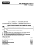
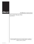
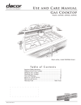
1
Installation Instructions
Gas Cooktop
Models: SGM304, SGM365, SGM466
Part No. 65141 Rev. M
Table of Contents
Important Safety Instructions........................................... 1
Important Information About Safety Instructions............... 1
General Safety Precautions.............................................. 2
Installation Specifications................................................. 3
Product Dimensions.......................................................... 3
Electrical Requirements.................................................... 4
Gas Supply Requirements................................................ 4
Cabinet and Countertop Layout........................................ 5
Installation Instructions..................................................... 8
Verify Package Contents................................................... 8
Installing the Cooktop....................................................... 8
Connecting the Gas Line.................................................. 8
Installing the Burner Components..................................... 9
Verifying Proper Operation................................................ 9
Installation Checklist....................................................... 10
Parts List..........................................................................11
Wiring Diagrams............................................................... 12
Before You Begin...
Important:
•
Installer: In the interest of safety and to minimize problems, read these installation instructions completely and carefully before you begin the installation process. Leave these installation instructions with the customer.
•
Customer: Keep these installation instructions for future reference and the local electrical inspector’s use.
NOTE: Dacor ® is not responsible for service required to correct a faulty installation.
Customer Service Information
If You Need Help...
Product Data Label
If you have questions or problems with installation, contact
your Dacor dealer or the Dacor Customer Service Team. For
repairs to Dacor appliances under warranty call the Dacor
Distinctive Service line. Whenever you call, have the model
and serial number of the appliance ready. The model and
serial number are printed on the product data label.
•
The product data label contains the model and serial
number information and the electrical and gas supply
requirements.
•
It is attached to the chassis on the bottom of the unit.
Dacor Customer Service
Phone: (800) 793-0093 ex 2813 (U.S.A. and Canada)
Monday — Friday 6:00 a.m. to 5:00 p.m. Pacific Time
Front of unit
Web site: www.dacor.com
Dacor Distinctive Service (repairs under warranty only)
Phone: ((800) 793-0093 ex 2822 (U.S.A. and Canada)
Monday — Friday 6:00 a.m. to 5:00 p.m. Pacific Time
Product data
label
All specifications are subject to change without notice. Dacor assumes no liability for changes to specifications.
© 2007 Dacor, all rights reserved.
Important Safety Instructions
Important Information About
Safety Instructions
IMPORTANT: If you smell gas:
•
•
Do not use or light any appliance.
•
Do not touch any electrical switch or use any electrical devices, including the telephone, in your building.
•
From a neighbor’s phone, immediately call the gas
supplier. Follow the gas supplier’s instructions.
•
If you cannot contact the gas supplier, call the fire
department.
•
The Important Safety Instructions and warnings in
these instructions are not meant to cover all possible
problems and conditions that can occur. Use common
sense and caution when installing, maintaining or operating this or any other appliance.
Always contact the Dacor Customer Service Team
about problems and conditions that you don’t understand. See Customer Service Information.
Safety Symbols and Labels
DANGER
Immediate hazards that WILL result in severe personal
injury or death.
warning
Hazards or unsafe practices that COULD result in severe
personal injury or death.
caution
Hazards or unsafe practices that COULD result in minor
personal injury or property damage.
warning
TO REDUCE THE RISK OF INJURY TO PERSONS IN
THE EVENT OF A RANGE TOP GREASE FIRE:
a. SMOTHER FLAMES with a close-fitting lid, cookie
sheet or metal tray, then turn off the burner. BE
CAREFUL TO PREVENT BURNS. If the flames do
not go out immediately, EVACUATE AND CALL THE
FIRE DEPARTMENT.
b. NEVER PICK UP A FLAMING PAN - you may be
burned.
c. DO NOT USE WATER, including wet dish cloths or
towels - a violent steam explosion may result.
d. Use a fire extinguisher ONLY if:
◊
You have a Class ABC extinguisher, and you
already know how to operate it.
◊
The fire is small and contained in the area where
it started.
◊
The fire department is being called.
◊
You can fight the fire with your back to an exit.
DANGER
DANGER
IMPORTANT: Do not store or use combustible, flammable
or explosive vapors and liquids (such as gasoline) on or
in the vicinity of this or any other appliance. Also keep
items that could explode, such as aerosol cans, away
from the cooktop. Do not store flammable or explosive
materials in adjacent cabinets or areas (including above
and below the cooktop).
warning
WARNING – NEVER use this appliance as a space
heater to heat or warm the room. Doing so may result
in carbon monoxide poisoning and overheating of the
appliance.
warning
WARNING – NEVER cover any slots, holes or passages
on the cooktop and cooktop chassis. Doing so blocks
air flow through the cooktop and may cause carbon
monoxide poisoning. Aluminum foil linings may also trap
heat, causing a fire hazard. Keep all slots, holes and
passages clear of grease and grime.
CALIFORNIA PROPOSITION 65
WARNING
The burning of gas cooking fuel generates some
by-products that are on the list of substances which
are known by the State of California to cause cancer or
reproductive harm. California law requires businesses
to warn customers of potential exposure to such
substances. To minimize exposure to these substances,
always operate this unit according to the use and care
manual, ensuring you provide good ventilation when
cooking with gas.
READ AND SAVE THESE INSTRUCTIONS
1
Important Safety Instructions
General Safety Precautions
To reduce the risk of fire, electric shock, serious injury or death when using your appliance, follow basic safety precautions, including the following:
WARNING
•
Read the accompanying use and care manual completely before operating this appliance.
•
Keep packaging materials away from children.
Plastic sheets and bags can cause suffocation.
•
If you receive a damaged product, immediately contact your dealer or builder. Do not install or use a
damaged appliance.
•
This cooktop must be properly installed and grounded by a qualified installer according to these installation instructions prior to use. The installer should
show the customer the location of the gas shut off
valve and the power cord so that they know where
and how to turn off the gas supply and disconnect
power to the cooktop.
warning
•
Do not leave children alone or unattended in the
area around the cooktop. Do not allow children to
play with the controls or touch other parts of the
cooktop. Do not store items of interest to children
on top of or above the cooktop. Children could be
burned or injured while climbing on the appliance.
•
Clean the cooktop thoroughly before operating it for
the first time. Make sure that all the cooktop parts
are dry before lighting a burner.
•
Keep flammable items, such as paper, cardboard,
plastic and cloth away from the burners and other
hot surfaces. Do not place such items on the
cooktop. Do not allow pot holders to touch hot surfaces or gas burners.
•
Do not wear loose or hanging apparel while using
the cooktop. Do not allow clothing to come into contact with the cooktop and surrounding areas during
and immediately after use.
•
Do not use this appliance in combination with a surface (countertop) ventilation system. Dacor strongly
recommends the installation of a range hood in conjunction with this appliance.
•
Do not install, repair or replace any part of the
cooktop unless specifically recommended in the literature accompanying it. A qualified service technician
should perform all other service.
•
Do not use towels or bulky cloth as pot holders.
•
Do not use the cooktop to heat sealed containers.
The container and contents may explode, causing
personal injury.
•
Before servicing or installing this cooktop, make sure
that the gas supply is turned off at the gas supply
valve and that the power plug is disconnected from
the electrical outlet.
•
If the cooktop is near a window, do not use long curtains as window treatment. The curtains could blow
over the cooktop and create a fire hazard.
•
Disconnect the power plug from the electrical outlet
before cleaning. Clean this appliance only in the
manner specified in the use and care manual.
•
Non-stick coatings, when heated, can be harmful to
birds. Remove birds to a separate, well-ventilated
room when operating the cooktop.
•
Only use the cooktop for cooking tasks expected of
a home appliance as outlined in the literature accompanying it. This cooktop is not intended for commercial or laboratory use.
•
DO NOT TOUCH THE SURFACES OF THE
COOKTOP DURING OR IMMEDIATELY AFTER
USE.
•
Do not operate this appliance if the power cord is
damaged.
•
Turn the knobs to the OFF position prior to removing
them from the valve stems.
•
Cut or remove the third (ground) prong from the
power cord.
•
To avoid a fire hazard, do not hang flammable or
heat sensitive objects over the cooktop.
•
Use an adapter plug.
Do not climb on any part of the appliance.
•
Use an extension cord.
•
Use a power cord that is frayed or damaged.
•
Connect to an electrical outlet with a ground fault
interrupter (GFI).
•
2
IMPORTANT - This appliance
is equipped with a threeprong grounding plug for your
protection against possible
electric shock hazards. Plug it
only into a dedicated, grounded
three-prong electrical outlet.
It is the responsibility of the
customer to make sure the proper type of outlet is
installed. Do not under any circumstances:
Installation Specifications
warning
Observe all governing codes and ordinances during planning and installation. Contact your local building department for
further information.
Product Dimensions
All tolerances ±1/16” (±1.6 mm) unless otherwise noted.
1 5/8" (4.1 cm)
bottom of base
to cooking surface
30"
(76.2 cm)
4" (10.2 cm)
chassis height
21"
(53.3 cm)
Model SGM304
27 5/8" *
(70.2 cm)
19 1/2" *
(49.5 cm)
1 5/8" (4.1 cm)
bottom of base
to cooking surface
* including embosses/screws in side of chassis
36"
(91.4 cm)
21"
(53.3 cm)
4" (10.2 cm)
chassis height
33 1/2" *
(85.1 cm)
19 1/2" *
(49.5 cm)
Model SGM365
4" (10.2 cm)
chassis height
* including embosses in side of chassis
46"
(116.8 cm)
1 5/8" (4.1 cm)
bottom of base
to cooking surface
21"
(53.3 cm)
44 5/8" *
(113.3 cm)
19 1/2" *
(49.5 cm)
Model SGM466
* including embosses/screws in side of chassis
3
Installation Specifications
Electrical Requirements
warning
To prevent an electric shock hazard, the power supply
must meet the specifications stated below. It is the owner’s responsibility to make sure that the electrical service
meets electrical requirements and that the electrical outlet
has been properly installed by a licensed electrician.
•
•
The cooktop is supplied with a factory installed,
40-inch, three-prong, grounding electrical plug. It is
connected to the chassis at the bottom right rear corner
(see Chassis Bottom Diagram below). It must be connected to a dedicated, grounded three-prong electrical
outlet installed by a licensed electrician.
The electrical installation, including minimum supply
wire size and grounding, must be done in accordance
with National Electric Code ANSI/NFPA 70* and local
codes and ordinances. A copy of this standard may be
obtained from:
National Fire Protection Association
1 Batterymarch Park
Quincy, MA 02269-9101
•
The correct voltage, frequency and amperage must be
supplied to the electrical outlet according to the product
data label located on the bottom of the chassis. See
the Gas and Electrical Requirements table on this
page for reference.
•
Be certain to locate the electrical outlet so that the
power cord may be easily disconnected if the unit
needs service.
Gas Supply Requirements
•
Be certain that the cooktop being installed is correct for
the gas service being provided (natural gas or LP gas).
Also, if operating the cooktop at an altitude above 4000
ft. (1219 m) make sure it is equipped for high altitude
operation.
•
Units equipped for LP operation have “LP” in the
model number listed on the product data label. See the
Chassis Bottom Diagram for label location.
•
Units equipped for high altitude operation have an “H”
at the end of the model number listed on the product
data label.
•
Check your local building codes for the proper method
of installation. In the absence of local codes, this
appliance should be installed in accordance with the
National Fuel Gas Code ANSI Z223.1/NFPA 54.
•
An external manual shut-off valve must be installed
between the gas inlet and the cooktop for the purpose
of turning on or shutting off gas to the appliance.
•
The cooktop comes from the factory with a regulator in
the shipping carton. The regulator must be installed in
the gas line that runs from the cooktop gas inlet to the
gas shut off valve. Use only the regulator provided.
•
Models SGM304 and SGM365 come with a 1/2” regulator. Model SGM466 comes with a 3/4” regulator,
approved for connection to a 1/2” house gas supply.
The cooktop gas connection is located on the bottom of the
cooktop in the back right corner as you face the front of the
unit. See the Chassis Bottom Diagram on this page.
SGM304
SGM365
SGM466
SGM304LP
SGM365LP
SGM466LP
Gas type
Natural gas
LP gas
Manifold
pressure
4” Water
column
10” Water
column
Min. gas supply
pressure **
5” Water
column
11” Water
column
Max. gas supply
pressure
1/2 psi
1/2 psi
Total connected
load
0.25 Amp.
(0.03 kW)
0.25 Amp.
(0.03 kW)
120 Vac,
60 Hz, 15 Amp.
120 Vac,
60 Hz, 15 Amp.
Front of unit
Product data label
Gas inlet Electric cord
Chassis Bottom Diagram
Circuit
requirement
Gas and Electrical Requirements*
* The electrical and gas data on this page is for reference
only. If the above data does not agree with the product data
label, use the data on the product data label.
** The gas supply pressure for testing the regulator setting
shall be at least 1 inch water column (249 Pa) above the
specified manifold pressure.
4
Installation Specifications
Cabinet and Countertop Layout
•
warning
•
To reduce the risk of personal injury caused by
reaching over a hot appliance, avoid locating cabinet
storage space directly above the cooktop.
•
Failure to meet or exceed the maximum and minimum dimensions/clearances stated in these instructions may result in a fire hazard.
•
Follow the countertop manufacturer’s instructions
regarding the minimum corner radius, use of heat
reflective tape, reinforcement of corners, etc.
•
•
Allow a minimum 1/4” (6 mm) clearance between the
bottom of the cooktop chassis and all combustible surfaces, including the upper edge of a drawer installed
below the cooktop.
B
Under Cabinet Clearances
Model
Carefully check the location where the cooktop will be
installed. For best performance, the cooktop should be
placed away from drafts that may be caused by doors,
windows and heating and air conditioning outlets.
This appliance is to be used in conjunction with a suitable vent hood or approved Dacor raised vent system.
•
A
18" min.
(45.7 cm)
1,
30" min. 2
(76.2 cm)
See cutout
dimensions
29” (73.7 cm)
SGM365
35 1/4” (89.5 cm)
SGM466
46” (116.8 cm)
The gas supply piping, gas shut-off valve and the electrical outlet must be located so they do not interfere
with the cooktop when it is installed. If installing another
appliance in the cabinet below, allow for the routing of
gas and electrical service behind it.
•
Access to the gas shut-off valve and regulator when
the unit is installed.
•
Access to the electrical outlet when the cooktop is in
place. The 40” (101.6 cm) power cord must be able to
reach the electrical outlet.
•
Access to the underside of the cooktop for service and
inspection purposes.
•
Clearance inside the cabinet to allow for proper hold
down bracket installation.
1, 3
Combustible
surface to rear
SGM304
The installation must allow for the following:
Combustible overhead
cabinets
13" max.
(33.0 cm)
B: Minimum*
* To allow clearance for hold down brackets
All tolerances +1/16” (+1.6 mm), -0
unless otherwise noted.
3
1/4” (6 mm)
min. clearance
to combustible
surfaces
1 7/8" min.
(4.8 cm)
7 1/2” (19.1 cm) min. to
combustible side wall,
above counter both sides
1
Measured from cooking surface (top of cooktop grate).
If installing with an overhead vent hood, also check hood
specifications for minimum required clearances.
3
Not applicable for cabinets more than a horizontal distance of 6”
(15.2 cm) from edge of cooktop. Allow 7 1/2” (19.1 cm) from edge
of cutout.
2
Minimum Required Clearances Around the Cooktop
Model
A: Minimum
SGM304
30” (76.2 cm)
36” (91.4 cm)
SGM365
36” (91.4 cm)
42” (106.7 cm)
SGM466
48” (121.9 cm)
54” (137.2 cm)
To allow access to the utilities and cooktop bottom, a fixed
shelf should not be installed below the cooktop. See the following pages for countertop cutout dimensions.
Raised Vent Compatibility
If installing the cooktop with a raised vent, install only the
approved Dacor model numbers specified below:
Cooktop Models
Approved Raised Vent Models
SGM304
ERV30, ERV3015, PRV30 or RV30
SGM365
ERV36, ERV3615, PRV36 or RV36
SGM466
PRV46 or RV46
A: Recommended
5
Installation Specifications
Cutout Dimensions
All tolerances +1/16” (+1.6 mm), -0, unless otherwise noted.
IMPORTANT: Be careful to use the correct cutout diagram (on the facing page) to determine the countertop dimensions
for the installation type. Carefully double check all dimensions against the table below and the correct diagram before cutting the countertop.
Countertop Dimensions
Cutout
Diagram
C Min.
D
E
F
G
H
SGM304 without raised
vent
Figure 1
(Square)
2 7/8”
(7.3 cm)
19 3/4”
(50.2 cm)
27 3/4”
(68.6 cm)
NA
NA
NA
SGM304 with ERV30,
ERV3015 and PRV30
Figure 1
(Square)
3/8”
(1.0 cm)
22 1/2”
(57.2 cm)*
27 3/4”
(68.6 cm)
NA
NA
NA
SGM304 with RV30
Figure 1
(Square)
5/8”
(1.6 cm)
22 1/4”
56.5 cm)*
27 3/4”
(68.6 cm)
NA
NA
NA
SGM365 without raised
vent
Figure 1
(Square)
2 3/8”
(6.0 cm)
19 3/4”
(50.2 cm)
33 5/8”
(85.4 cm)
NA
NA
NA
SGM365 with ERV36,
ERV3615 and PRV36
Figure 1
(Square)
3/8”
(1.0 cm)
22 1/2”
(57.2 cm)*
33 5/8”
(85.4 cm)
NA
NA
NA
SGM365 with RV36
Figure 1
(Square)
5/8”
(1.6 cm)
22 1/4”
(56.5 cm)*
33 5/8”
(85.4 cm)
NA
NA
NA
SGM466 without raised
vent
Figure 1
(Square)
2 7/8”
(7.3 cm)
19 3/4”
(50.2 cm)
44 3/4”
(113.7 cm)
NA
NA
NA
SGM466 with PRV46
Figure 2
(Notched)
3/8”
(1.0 cm)
22 1/2”
(57.2 cm)*
44 3/4”
43 1/2”
(113.7 cm) (110.5 cm)
5/8”
(1.6 cm)
2 5/8” **
(6.7 cm)
SGM466 with RV46
Figure 2
(Notched)
5/8”
(1.6 cm)
22 1/4”
(56.5 cm)*
44 3/4”
43 1/2”
(113.7 cm) (110.5 cm)
5/8”
(1.6 cm)
2 3/8” **
(6.0 cm)
Installation Type
* Total cutout depth, accommodates both the cooktop and raised vent
** IMPORTANT: Notch depth is included in total cutout depth (D). DO NOT add notch depth to total cutout depth (D).
3/8” min. (1.0 cm)
flat countertop overhang
required behind cutout
Stiffener
Countertop
SGM series cooktop
Cabinet face
3/8” min. (1.0 cm) space
behind raised vent
chassis to clear stiffener
ERV or PRV series raised
vent: Check raised vent
dimensions/specifications
to determine proper fit
Floor
Side View - SGM Series Cooktop with
ERV or PRV Series Raised Vent
6
5/8” min. (1.6 cm)
flat countertop overhang
required behind cutout
Stiffener
Countertop
SGM series cooktop
Cabinet face
5/8” min. (1.6 cm) space
behind raised vent
chassis to clear stiffener
RV series raised vent:
Check raised vent
dimensions/specifications
to determine proper fit
4 5/8” (11.7 cm)
9 7/8” (25.1 cm) with
CABP3 blower installed
Floor
Side View - SGM Series Cooktop with
RV Series Raised Vent
Installation Specifications
Rear
wall
Vertical
combustible
surface
4 1/4" (10.8 cm) min.
from mounting surface to
combustibles below
cooktop chassis
C
E
7 1/2" (19.1 cm) min.
to combustible
side wall above
countertop
(both sides)
D
1 7/8" min.
(4.8 cm)
Figure 1 - Square Countertop Cutout Diagram
4 1/4" (10.8 cm) min. from
mounting surface to combustibles
below cooktop chassis
Rear
wall
H
Vertical
combustible
surface
G
C
F
H
E
7 1/2" (19.1 cm) min.
to combustible
side wall above
countertop
(both sides)
D
1 7/8" min.
(4.8 cm)
Figure 2 - Notched Countertop Cutout Diagram
7
Installation Instructions
Verify Package Contents
•
Hold down brackets (2)
•
Gas pressure regulator
•
Grates (2 for SGM304, 3 for SGM365 and SGM466)
•
Burner sets (4 for SGM304, 5 for SGM365, 6 for
SGM466)
•
Stainless steel cleaner (stainless steel models only)
Connecting the Gas Line
warning
If any parts are missing, see the Parts List section on
page 11 for ordering information.
Installing the Cooktop
WARNING
•
Verify that the power supply meets the specifications
on page 4 before proceeding.
•
To prevent damage to the gas pressure regulator,
install it only after the cooktop is mounted in its permanent position.
•
Verify that the gas supply meets specifications before
connection. See page 4.
•
Do not install or use the cooktop without the included
gas regulator installed.
•
Ensure that the arrow on the regulator points in the
direction of the gas flow, towards the cooktop.
•
Do not apply excessive pressure when tightening gas
connections and fittings.
•
Do not use Teflon tape or plumber’s putty on flexible
gas line connections.
•
Test the gas lines for leaks as instructed before use.
Do not use a flame to check for leaks.
•
The maximum gas supply pressure to the regulator
must never exceed 1/2 pounds per square inch (psi)
or 3.5 kPa.
•
The cooktop and shut-off valve must be disconnected
from the gas supply piping system during any pressure testing exceeding 1/2 psi (3.5 kPa).
•
The cooktop must be isolated from the gas supply
piping system by closing the shut-off valve to the
cooktop during any gas supply piping system pressure testing equal to or less than 1/2 psi (3.5 kPa).
•
For LP gas installations, the LP gas tank must have
its own high-pressure regulator in addition to the
pressure regulator supplied with the cooktop.
important
•
Do not over-tighten the hold down bolts. Over tightening the hold down bolts may result in improper
operation of the dual gas burners.
•
Do not use a hardening compound or caulk to permanently seal the cooktop into place. The cooktop must
be readily removable if service is required. Removal
of sealant to service the unit will be performed at the
customer’s expense.
1. If the cooktop will be used with a raised vent, install the
vent according to it’s installation instructions first.
2. Lower the cooktop into the cutout and center it.
3. Secure the cooktop to the countertop using the two (2)
provided hold-down brackets as shown.
1. Attach the gas pressure regulator (included with the
cooktop) to the cooktop pipe nipple inlet. For tight
installations, the regulator may be installed upstream
from the pipe nipple, anywhere between the shut-off
valve and the cooktop. For best performance, minimize
gas pressure loss by attaching the regulator as close
as possible to the cooktop gas inlet.
2. Complete connection of the gas supply to the cooktop
by installing a minimum 1/2” flexible gas line (not
included) between the pressure regulator and the shutoff valve.
Hold down bracket
mounting holes
(both sides)
3. Check for gas leaks:
Gas inlet
◊
Turn all cooktop control valves to the OFF position.
◊
Turn on the gas supply valve and check all lines
and connections for leaks using a soap and water
solution or a gas leak detector.
◊
Turn the gas supply off.
Electric cord
Hold Down
Bracket Installation
8
Installation Instructions
Installing the Burner Components
Verifying Proper Operation
warning
warning
•
Never attempt to operate the cooktop with any of the
burner parts removed.
•
Do not attempt to adjust the burner air mixture settings. All adjustments are preset at the factory.
1. Remove the burner heads, burner rings, burner caps
and grates from their shipping packages.
2. Install the burners as shown. When installing the burner components, twist each piece back and forth slightly
until it drops completely into place. The burners will
not operate properly unless all of the burner pieces are
properly seated.
3. Gently set the grates on top of the spill tray. Make sure
that the rubber feet are positioned in the dimples.
•
Make sure that power to the electrical outlet is turned
off at the circuit breaker panel or fuse box and that
the gas is turned off at the gas supply valve before
proceeding.
•
The cooktop must be properly grounded at all times
when electrical power is applied.
Prior to operating the cooktop, read the accompanying use
and care manual carefully.
1. Make sure all the cooktop burner controls are in the
OFF position.
2. Connect the power cord to the electrical outlet.
3. Turn on power to the electrical outlet at the circuit
breaker or fuse box.
4. Depress and turn one burner control knob at a time
slowly counterclockwise to the HIGH position. Verify
that the associated burner igniter sparks, then return
the knob to the OFF position. Repeat for all of the
remaining control knobs.
Grate
Burner cap
Burner ring
Top frame
Burner head
(fixed)
5. Turn on the gas supply valve.
6. Perform the following ignition test for all of the burners:
•
Press and turn the control knob slowly counterclockwise to the HIGH position. Only the selected
burner will spark. It may take up to four seconds
for the burner to ignite, at which time the igniter
will stop sparking. If ignition does not occur within
four seconds, turn off the knob, wait for at least five
minutes to allow any gas to dissipate, then repeat
the test.
Knob
Cooktop Burner Components
Tabs
5 places
Low
position
Off position
Notches
5 places
Area of
operation
Knob position
indicator
(polished surface)
Burner
designation
Light and high
position
Burner Control Knob
Burner Ring Installation Detail
Continued...
9
Installation Instructions
Verifying Proper Operation (cont) Installation Checklist
•
Once the burner lights, rotate the control knob
counterclockwise from HIGH to LOW to adjust the
flame height progressively.
•
When the unit is installed properly, the flame will
be steady. It will also have a sharp, blue inner cone
that will vary in length proportional to the burner
size. The flame will be reduced by the Smart
Flame™ feature under the grate fingers to increase
grate life.
warning
To ensure a safe and proper installation, the following
checklist should be completed by the installer to ensure
that no part of the installation has been overlooked.
Proper installation is the responsibility of the homeowner.
The importance of proper installation of your Dacor
cooktop cannot be overemphasized.
□□ Is the electrical outlet for the cooktop grounded and
located according to these instructions and in accordance with all applicable electrical codes? See page
4.
□□ Is the gas service for the cooktop located and installed
according to these instructions and in accordance with
all applicable codes? See page 4.
□□ Has the gas supply inlet pressure been measured to
Normal Flame Appearance
NOTE: If the cooktop does not operate properly, follow
these troubleshooting steps:
•
Verify that power and gas are supplied to the cooktop.
•
Check to make sure that the power plug is connected
to the electrical outlet and that power is turned on at
the circuit breaker or fuse box.
•
Check to make sure that the burners are properly
seated.
•
If the burner continues to spark after ignition without
stopping, have a licensed electrician check the electrical outlet for proper grounding or reversed polarity.
•
Repeat the above burner ignition test.
•
If the appliance still does not work, contact Dacor
Distinctive Service at (877) 337-3226. Do not attempt
to repair the appliance yourself. If you need service, be
sure to have the model and serial numbers available
when you call. See inside cover for location.
Dacor is not responsible for the cost of correcting problems
caused by a faulty installation.
10
ensure that it does not exceed the maximums stated in
these instructions? See page 4.
□□ Is the cooktop secured using the provided hold-down
brackets? See page 8.
□□ Is the cooktop connected to the gas supply according
to these instructions and in accordance with all applicable codes? Did the installer check the gas supply for
leaks? See page 8.
□□ Are the burners and grates properly installed according
to these instructions? See page 9.
□□ Has proper operation been verified?
□□ Has the warranty been activated on-line or the warranty
card filled out completely and mailed?
Installation Instructions
Parts List
SGM466
Replacement parts may be obtained by contacting Dacor
Customer Service.
Dacor Customer Service
Phone: (800) 793-0093 (U.S.A. and Canada)
Monday — Friday 6:00 a.m. to 5:00 p.m. Pacific Time
Parts Used on All Models
Description
Dacor Part
Number
Hold down bracket w/screws
(2 sets)
12269
Stainless steel cleaner
(stainless steel models only)
A302
Description
Regulator (natural gas)
Regulator (LP)
Dacor Part
Number
62320
62434
Grate
82926SB
Burner cap - left front, right front
72435SB
Burner ring - left front, right front
86918
Burner cap - left rear, center front, right rear
86524SB
Burner ring - left rear, center front, right rear
86408
Burner cap - center rear
86523SB
Burner ring - center rear
86407
SGM304
Description
Regulator
Dacor Part
Number
82540
Grate
82925SB
Burner cap - left front
72435BM
Burner ring - left front
86918
Burner cap - left rear, right front
86524BM
Burner ring - left rear, right front
86408
Burner cap - right rear
86523BM
Burner ring - right rear
86407
SGM365
Description
Regulator
Grate - large
Dacor Part
Number
82540
82925SB
Grate - small
62443SB
Burner cap - left front
72435BM
Burner ring - left front
86918
Burner cap - left rear, right front
86524BM
Burner ring - left rear, right front
86408
Burner cap - center rear, right rear
86523BM
Burner ring - center rear, right rear
86407
11
Wiring Diagrams
12
Wiring Diagrams
13
Wiring Diagrams
14
Notes
15
Notes
16
Dacor ● 14425 Clark Avenue, City of Industry, CA 91745 ● Phone: (800) 793-0093 ● Fax: (626) 403-3130 ● www.dacor.com