1
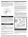
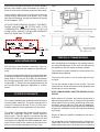
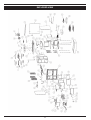
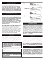
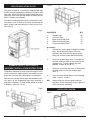
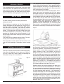
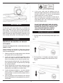
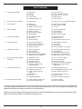
RAYBURN 370 SFW
To ensure safety, satisfaction and maximum service, this Cooker should be installed by a suitably qualified
and competent person. The provision of a Central Heating facility, requires that the hot water systems involved,
conform fully to good plumbing practice and established standards.
INSTALLATION INSTRUCTIONS
TABLE OF CONTENTS
Page No.
1.
Technical Data .................................................................................................................................. 3
2.
Specification ......................................................................................................................................4
3.
Electrical Connections........................................................................................................................4
3.
Site Preparation .................................................................................................................................5
4.
Cooker Position..................................................................................................................................5
5.
Builders Opening................................................................................................................................5
6.
The Chimney......................................................................................................................................5
7.
Cooker Flue Connection ....................................................................................................................6
8.
Flue Layouts.......................................................................................................................................7
9.
Ventilation & Combustion Air Requirements ......................................................................................7
10.
Flue Box .............................................................................................................................................8
11.
Central Heating & Hot Water Systems ...............................................................................................8
12.
Central Heating Pump Control ...........................................................................................................8
13.
High Up-Draughts ..............................................................................................................................9
14.
Cooker Clearance ..............................................................................................................................9
15.
Testing & Commissioning...................................................................................................................9
16.
CO Alarm..........................................................................................................................................10
17.
Exploded View..................................................................................................................................11
18.
Parts List ..........................................................................................................................................12
2
Consumer Protection Act 1987
As responsible manufacturers, we take care to make
sure that our products are designed and constructed to
meet the required safety standards when properly installed and used.
Firebricks, Fuel beds, Fuels - when handling use
disposable gloves.
Fire Cement - when handling use disposable gloves.
In case of skin contact wash immediately with plenty of
water.
IMPORTANT NOTICE: PLEASE READ THE ACCOMPANYING WARRANTY: Any alteration that is not approved by AGA, could invalidate the approval of the
appliance, operation of the warranty and could also affect your statutory rights. Use only authorised replacement parts.
Glues and Sealants - exercise caution - if these are
still in liquid form use face mask and disposable gloves.
Glass Yarn, Mineral Wool, Insulation Pads,
Ceramic Fibre, Kerosene Oil - may be harmful if
inhaled, may be irritating to skin, eyes, nose and throat.
When handling avoid inhaling and contact with skin or
eyes. Use disposable gloves, face-masks and eye protection. After handling wash hands and other exposed
parts. When disposing of the product, reduce dust with
water spray, ensure that parts are securely wrapped.
All local regulations including those referring to
national and European standards need to be
complied with when installing the appliance.
Control of Substances - Health and Safety
Important
This appliance may contain some of the materials that
are indicated. It is the Users/Installers responsibility to
ensure that the necessary personal protective clothing
is worn when handling, where applicable, the pertinent
parts that contain any of the listed materials that could
be interpreted as being injurious to health and safety,
see below for information.
Handling Adequate facilities must be available for loading, unloading and site handling.
Asbestos
This stove contains no asbestos. If there is a possibility
of disturbing any asbestos in the course of installation
then please seek guidance and use appropriate
protective equipment.
TECHNICAL DATA
Manufactured Smokeless Fuel (Ancit)
Mode
Total Output (kW)
Room Output (kW)
Boiler Output (kW)
Efficiency
Winter
21.6
8.2
13.4
72.7
Summer
12.2
4.3
7.9
69.8
Typical Refuelling Interval To Obtain Nominal Outputs:
2.0 hrs
Flue Gas Temperature At Nominal Output:
231-260oC
Flue Gas Mass Flow:
14.1-16.9 g/s
Wood Logs
Mode
Total Output (kW)
Room Output (kW)
Boiler Output (kW)
Efficiency
Winter
15.3
5.3
10.0
69.9
Summer
10.9
4.7
6.2
63.6
Typical Refuelling Interval To Obtain Nominal Outputs:
1.0 hrs
Flue Gas Temperature At Nominal Output:
269-282oC
Flue Gas Mass Flow:
18.8-21.3 g/s
Maximum Log Length
380mm
3
General
Gross Weight:
400kg
Flue Outlet Diameter:
150mm
Max Water Pressure:
1.79 Bar
Minimum Flue Draught:
15 pa
Boiler Water Capacity:
20 Litres
SPECIFICATION
Fig.1
*(Int.)
*(Int.)
WARNING:- THIS APPLIANCE MUST NOT BE USED WITHOUT WATER CONNECTED, OTHERWISE
DAMAGE TO THE BOILER MAY BE CAUSED AND/OR HEAT DAMAGE TO SURROUNDING
SURFACES.
* (Int.) Internal Thread
ELECTRICAL CONNECTIONS
The installation of any electrical services during
the installation of this cooker with boiler and the
associated heating system must be carried out
by a registered competent electrician and in
accordance with the requirements of the latest
issue of BS 7671.
4
Checking existing chimney
The internal and external condition of the chimney
should be checked before the appliance is installed
and rectification made where necessary to prevent
leakage or porosity. The soundness of the chimney
which should have a minimum flue dimension of
150mm diameter can be confirmed by smoke testing
Advice on the test method can be obtained from
HETAS.
SITE PREPARATION
The non-combustible hearth must be solid and level
and together with the walls adjacent to the cooker and
chimney, conform to current Building Regulations.
The cooker and chimney flue installation should be in
accordance with current issues of British Standards
BS EN 15287-1:2007 design, installation and commissioning of chimneys. BS EN 14336:2004: Heating
Systems in Buildings. Installation and commissioning
of water based heating systems. BS EN 12828: 2003;
Heating Systems in Buildings. Design of water based
heating systems. BS EN 12831: 2003; Heating Systems in Buildings. Method for calculation of the design
heat load. As applicable to the appliance. The boiler
installation section must also be in accordance with
the byelaws of the local Water Undertaking,
Regulations for the Electrical Equipment of Buildings
published by the Institute of Electrical Engineers and
any relevant requirements of the Local Authority.
When repairing or re-using chimneys its recommended that the building control office be consulted
before the commencement of work with particular
attention to the chimney height and its termination.
The chimney must be swept before installation.
Erecting New Chimney
The flue through the chimney should be formed with
pre-cast moisture and acid-resistant liners with a minimum internal dimension of 185mm square and all in
accordance with the current Building Regulations
(England and Wales) and in Scotland the Building
Standards (Scotland) (Consolidation) Regulations
and the Codes of Practice for chimneys and flues BS.
6461 Part 1 and BS 7566 Parts 1 to 4.
Ensure that any electrical wiring is correctly earthed.
COOKER POSITION
Ensure the chimney liners are free of projecting internal building jointing composition before the appliance
is installed.
When the cooker is installed in a recess it must be
‘freestanding’ and not built-in solid at the sides. Ensure that any combustible material e.g. kitchen furniture is spaced away from the cooker to the
recommended distances. See Clearance to
Combustibles Section.
Factory made Insulated Chimneys
It is recommended the chimney be ceramic lined and
comply with BS. 4543.
The minimum chimney diameter is 150mm.
BUILDERS OPENING
IN ALL TYPES OF CHIMNEYS THE MINIMUM
HEIGHT FOR CORRECT OPERATION OF THE
COOKER IS 4.8m AND SHOULD TERMINATE
ABOVE THE ROOF IN ACCORDANCE WITH
REGIONAL STATUTORY REQUIREMENTS.
The fireplace recess should comply with current building regulations, and have an opening of 1,080mm
wide minimum, by 343mm deep minimum and
1,680mm high minimum from floor is recommended.
RECOMMENDED FLUE DRAUGHT - 15Pa/.06” WG
MINIMUM. THE APPLIANCE SHOULD BE
INSTALLED AND CONFORM TO THE CURRENT
CODES OF PRACTICE FOR INSTALLATION OF
DOMESTIC HEATING AND COOKING APPLIANCES BURNING SOLID FUEL - BS 8303.
PLEASE NOTE: IT IS ADVISABLE TO CHECK THE
SIZE/WIDTH OF YOUR APPLIANCE BEFORE
FINALLY FIXING ANY KITCHEN UNITS SINCE
ENAMELLED CAST IRON CAN VARY IN SIZE.
THE CHIMNEY
ALWAYS ADVISE THE USER TO CLEAN THE
COOKER FLUES IN ACCORDANCE WITH THE
OPERATING INSTRUCTIONS AND TO HAVE THE
CHIMNEY SWEPT AT A MINIMUM OF 6 MONTHLY
INTERVALS AFTER THE COOKER IS COMMISSIONED. A VISUAL INSPECTION SHOULD BE
CARRIED OUT MONTHLY.
The minimum chimney draught requirement at nominal total heat output is 15 Pa/.06” WG.
This appliance is not suitable for installation in a
shared flue system.
5
Where the chimney is believed to have previously
served an open fire installation it is possible that the
higher flue gas temperature from a closed appliance
may loosen deposits that were previously firmly adhered, with the consequent risk of flue blockage. It is
therefore recommended that the chimney be swept a
second time within a month of regular use after installation.
WARNING: PROLONGED SOOT FORMATION MAY
RESULT IN THE FLUEWAYS BECOMING
BLOCKED AND COULD GIVE RISE TO THE RELEASE OF CARBON MONOXIDE, A POISONOUS
GAS, INTO THE ROOM.
COOKER FLUE CONNECTION
Fig. 2
DESN 515206
The position of available types of flue layouts are
shown in Figs. 2, 3 and 4, the cooker flue chamber is
adaptable to provide either top or back flue outlets,
by means of the reversible loose socket.
(a) Rear Flue Outlet
This must only be used where there is a brick flue
immediately behind the cooker. Provision must be
made for a condensate collecting vessel and
cleaning door. See Fig. 3.
NOTE: MAXIMUM HORIZONTAL LENGTH 150mm.
EXTENDED REAR FLUE PIPE AND BENDS
ARE NOT RECOMMENDED.
(b) Top Flue Outlet
The cooker should be connected to the main flue
via a 150mm minimum diameter cast iron pipe or
appropriately sized vitreous enamelled mild steel
pipe and be sealed to the cooker flue chamber
with soft rope and fire cement.
Fig. 3
DESN 515207
Fig. 4
DESN 515208 A
Any bends in the flue pipe must be not less than
135º (45º from horizontal) and be complete with
a cleaning door.
A minimum 6” vertical length of flue pipe must be fitted
before any bend is included.
6
This increases to 141.1cm2 where a flue draught stabiliser is fitted. If another appliance is fitted in an adjacent room it will be necessary to calculate an
additional air supply.
FLUE LAYOUTS
In Fig. 2. the cooker is installed in an existing recess.
There must be a clearance of not less than 150mm
between the top of the flue pipe and any overhanging
brickwork.
All materials used in the manufacture of air vents
should be such that the vent is dimensionally stable,
corrosion resistant, and no provision for closure. The
effective free area of any vent should be ascertained
before installation. The effect of any grills should be
allowed for when determining the effective free area
of any vent.
Any cavities or pockets above the register plate
should as far as possible be filled and if necessary
the flue pipe should be extended into the throat of the
chimney and soot door provided for chimney sweeping.
If a flue liner or insulated chimney is used, the size
should not be less than 150mm diameter.
Air vents direct to the outside of the building should
be located so that any air current produced will not
pass through normally occupied areas of the room.
There are two Isokern pumice liners which are also
recommended. One is the standard 175mm diameter
and the other is a 170mm thin wall. The thin wall has
a smaller outer diameter and is designed to fit an existing chimney system. Both have a lifetime guarantee.
An air vent outside the building should not be located
less than the dimensions specified within the Building
Regulations and B.S. 8303: Part 1 from any part of
any flue terminal. These air vents must also be satisfactorily fire proofed as per Building Regulations and
B.S. 8303: Part 1.
In Fig. 3, the cooker is connected direct to a brick flue.
Horizontal pipe runs between cooker and brick flue
must not be used.
Air vents in internal walls should not communicate
with bedrooms, bedsits, toilets, bathrooms or rooms
containing a shower.
In Fig. 4, the cooker is connected to an existing brick
flue with a length of flue pipe. Square bends and horizontal runs must not be used. There must be a
cleaning door at every bend.
Air vents traversing cavity walls should include a continuous duct across the cavity. The duct should be installed in such a manner as not to impair the weather
resistance of the cavity.
NOTE: WHATEVER METHOD OF INSTALLATION IS
EMPLOYED, AIR MUST NOT BE ALLOWED TO
ENTER THE CHIMNEY EXCEPT THROUGH THE
COOKER. ALL JOINTS MUST BE AIR-TIGHT.
Joints between air vents and outside walls should be
sealed to prevent the ingress of moisture. Existing air
vents should be of the correct size and unobstructed
for the appliance in use. If there is an extraction fan
fitted in adjacent rooms where this appliance is fitted,
additional air vents may be required to alleviate the
possibility of spillage of products of combustion from
the appliance/flue while the fan is in operation. There
must not be an extractor fan fitted in the same room
as the appliance.
If the chimney is unlined, and there is any doubt about
its condition, it should be lined in accordance with current Building Regulations.
PROVISION MUST ALWAYS BE MADE FOR
SWEEPING THE CHIMNEY.
IMPORTANT: CEMENT TYPE PIPES AND FITTINGS MUST NOT BE USED WITHIN 2m. OF THE
COOKER. CHIMNEYS OF PLAIN PIPE ARE NOT
RECOMMENDED BUT CERTAIN PROPRIETARY
MAKES OF INSULATED CHIMNEY ARE SUITABLE.
Where such an installation exists, a test for spillage
should be made with the fan or fans and other appliances using air in operation at full rate, (i.e.extraction
fans, tumble dryers) with all external doors and windows closed.
If spillage occurs following the above operation, an
additional air vent of sufficient size to prevent this occurrence should be installed.
VENTILATION & COMBUSTION AIR
REQUIREMENTS
It is imperative that there is sufficient air supply to the
cooker in order to support correct combustion. The
air supply to this appliance must comply with current
t Building Regulations. The minimum effective air
requirement for this appliance is 91.3cm2.
7
Especially Airtight Properties:-
In combined systems, the water draw-off pipes to the
taps must be dead-leg connection from the vent/expansion pipe.
If the cooker is being fitted in a property where the
design air permeability is less than 5m3 / (h.m2) (normally newer properties built from 2006), then a permanent ventilation must be fitted to provide 550mm2
of ventilation for each kW of rated output. If a draught
stabiliser is also fitted then the requirement is
850mm2 per kW of rated output.
There are only two boiler tappings on this cooker and
a typical design layout is shown in Fig. 6.
An injector tee is provided which must be fitted to ensure adequate primary flow circulation when the water
circulator is operating, otherwise there may be a lack
of domestic hot water. The heating flow and return
pipes may be 22mm, the return pipe being connected
to the 28mm primary return by the injector tee, and
the tee outlet connected to the boiler return pipe.
Fig.5
All installations must be fitted with a drain tap at the
lowest point of the system.
Inhibitor
A corrosion inhibitor MUST be added to the heating
system to protect the heat exchanger and pipework.
Inhibitor must also be replaced if the system is
drained after installation. As a precaution, the heating
system MUST also be flushed out prior to the addition
of the inhibitor to ensure any flux, debris is removed.
FLUE BOX
Fig.6
Apply fire cement to the socket in the hob. Attach a
short length of 6” (150mm) I.D. pipe approx. 10”
(250mm) long to the outlet of the flue box by means
of fire cement. Place the flue box on the hob and the
pipe into the wall and consolidate the fluebox and pipe
into the fire cement. Apply 3 or 4 coils of 10mm (1/2’)
insulating rope to the pipe and fill the wall cavity with
fire cement. (See fig. 5).
CENTRAL HEATING AND
HOT WATER SYSTEM
THIS APPLIANCE MUST NOT BE USED WITHOUT
WATER CONNECTED.
Typical Central Heating/Hot
Water System
It is recommended that a 190 litre (40 galls) indirect
hot water storage cylinder of the double feed type e.g.
(Complying with BS. 1566 Part 1:DF Type 10) should
be lagged and fixed vertically as near as possible to
the cooker.
CENTRAL HEATING PUMP CONTROL
The 28mm minimum diameter primary flow and return
pipes must not exceed 10m in length and pipes longer
than 5m must be lagged.
The central heating pump must be controlled by fitting
a pipe thermostat on the flow pipe as close as possible to the cooker. If it is used on its own it should be
set to approx. 55oC
Ensure that the flow pipe has an open vent and rises
continuously from the boiler to the cylinder to ensure
good gravity circulation.
8
Fig.8
Alternatively the pipe thermostat (A) can be wired in
parallel with another pipe thermostat (b) which is
wired in series with a timeclock and room thermostat.
Worktop
Worktop
In this instance priority can be given to hot water by
setting the pipe thermostat (A) to approx. 85oC used
only to prevent boiling, the pipe thermostat (B) should
be set to approx. 55oC.
AT LEAST ONE RADIATOR (USUALLY THE BATHROOM) SHOULD NOT BE FITTED WITH A TRV
(THERMOSTATIC RADIATOR VALVE), TO ACT AS
A HEAT LEAK, SHOULD THE BOILER OVERHEAT
AND THE PUMP FAIL TO START.
75
Back filler piece
75
Gap between Cooker & Kitchen units
must be filled using a filler strip
Fig.7
Fig.8a
Cooker front must be
kept in line with front
of kitchen unit.
TESTING & COMMISSIONING
HIGH UPDRAUGHTS
After completing the installation, the heating contractor should demonstrate to the user the operation of
the appliance and the routine cleaning method.
Tall chimneys may develop excessively high updraughts which prevent the appliance operating correctly.
The protective grease should be removed from the
hotplate before lighting.
It is recommended that a proprietary brand adjustable
flue draught stabiliser having an openable cross sectional area of 182.5sq cm (6”ø pipe) be fitted above
the flue pipe connection, either in the brickwork or into
a right angle ‘T’; fitting in the flue pipe position that will
not inconvenience appliance operation or maintenance.
Check that the system is full of water and free from
air locks.
For the first couple of days do not overfire. The cast
iron inside the cooker will build up heat gradually and
overfiring may cause damage.
COOKER CLEARANCE
NOTE: SMOKE/SMELL EMITTED DURING INITIAL
USAGE
The Cooker should not be installed at zero clearance
to combustible materials. The sides should have a
minimum clearance of at least 75 mm (3”) from combustible materials unless otherwise fully insulated.
Some parts of the cooker have been coated with a
light covering of protective oil. During initial operation
of the cooker, this may cause smoke/smell to be emitted and is normal and not a fault with the appliance,
it is therefore advisable to open doors and or windows
to allow for ventilation. Lift the lids to prevent staining
the linings.
This cooker is supplied with a back filler piece which
should be used with fitting the cooker between
kitchen units. This filler piece is mounted to the wall
behind the cooker using the appropriate screws and
rawl plugs (not supplied) and allows adequate clearance from the front of the cooker to the front of the
kitchen units for door opening (see Fig.8 & 8a)
Ensure all parts are fitted in accordance with the instructions.
On completion of the installation allow a suitable period of time for any fire cement and mortar to dry out,
before lighting the stove. Once the stove is under fire
9
check all seals for soundness and check that the flue
is functioning correctly and that all products of combustion are vented safely to atmosphere via the chimney terminal.
On completion of the installation and commissioning
ensure that the operating instructions for the stove are
left with the customer. Advise the user what to do
should smoke or fumes be emitted from the stove.
Building Regulations require that whenever a new or
replacement fixed solid fuel or wood/biomass appliance is installed in a dwelling a carbon monoxide
alarm must be fitted in the same room as the appliance. Further guidance on the installation of the carbon monoxide alarm is available in BS EN
50292:2002 and from the alarm manufacturer’s
instructions.
CO ALARM
Provision of an alarm must not be considered a
substitute for either installing the appliance correctly or ensuring regular servicing and maintenance of the appliance and chimney system.
Your installer should have fitted a CO alarm in the
same room as the appliance. If the alarm sounds
unexpectedly, follow the instructions given under
“Warning Note” below.
WARNING:If the CO Alarm sounds unexpectedly:1. Open Doors and windows to ventilate the
room and then leave the premises.
2. Let the fire go out.
10
EXPLODED VIEW
11
PARTS LIST
No.
1.
2.
3.
4.
5.
6.
7.
8.
9.
10.
11.
12.
13.
14.
15.
16.
17.
18.
19.
20.
21.
22.
23.
24.
25.
26.
27.
28.
29.
30.
31.
32.
33.
34.
35.
36.
37.
38.
39.
40.
41.
42.
43.
44.
45.
46.
47.
48.
49.
50.
51.
52.
53.
54.
55.
Description
Code
No.
Description
Code
Spin Valve
Front Cleaning Door
Bonnet Blanking Plate
Fire Door
Oven Door
Ash Door
Warming Oven Door
Ash Door Back
Bonnet
Bonnet Cover
Bonnet Spin Valve
Trivet
Front
Hob
Riddling Handle
Thermostat Holder
Side Panel
Back Panel
Upper Blanking Plate
Front Cover Plate (Short)
Front Cover Plate (Long)
Fire Bar Link
Donard SF Ashpan
Base
Boiler
Lower Blank Plate
Main Oven Door Panel
Warming Oven Door Panel
RH Strap
Base Plate
Fix Plate RH
Fix Plate LH
Hob Back Filler Piece
Oven Side Flue Plate
Hinge Cover Plate
Thermostat Without Knob
Thermometer 100 to 300
Main Oven Door Insulation
Warming Door Insulation
Serial Number Plate
Gasket (200 * 43 * 2mm)
Silicone Oven Seal 266mm
Silicone Oven Seal 312mm
Silicone Oven Seal 416mm
Steam Escape
Riddling Grate
Fire Bar Standard
Fire Bar Frame
Hotplate
Cleaning Plateto Hotplate
Front Cleaing Door Clip
Summer Grate Support
Summer Front Brick
Summer Back Brick
Summer Side Brick
B00032AXX
B00164BXX
B00296AXX
B00558AXX
B00559AXX
B00560AXX
B00561AXX
B00562AXX
B00571AXX
B00572AXX
B00573AXX
B00574AXX
B00584AXX
B00644AXX
F00063AXX
F00076AXX
F00078AXX
F00079CXX
F00082AXX
F00083AXX
F00084AXX
F00097AXX
F00100AXX
F00101DXX
F00102DXX
F00117AXX
F00906AXX
F00907AXX
F00911BXX
F00914AXX
F00915AXX
F00916AXX
F00986AXX
F01001AXX
F01257AXX
G00004AXX
G00519AXX
J00230AXX
J00231AXX
N00234BXX
P00011BXX
P00097AXX
P00098AXX
P00099AXX
Q00107AXX
Q00113AXX
Q00148AXX
Q00149AXX
Q00152AXX
Q00154AXX
Q00158AXX
Q00162AXX
Q00163AXX
Q00164AXX
Q00165AXX
56.
57.
58.
59.
60.
61.
62.
63.
64.
65.
66.
67.
68.
69.
70.
71.
72.
73.
74.
75.
76.
77.
78.
79.
80.
81.
82.
83.
84.
85.
86.
87.
88.
89.
90.
91.
92.
93.
94.
95.
96.
97.
98.
99.
100.
101.
102.
103.
104.
105.
106.
107.
Baffle
Base Plate
Oven Bottom Back
Oven Bottom Side (Left)
Oven Bottom Side (Right)
Oven Bottom
Top Oven Back
Right Side Oven Top
Top Oven Side (Left)
Oven Top
Fire Bar Special
Cleaning Plate To Hob
Flue Way Right
Fire Door Back
Oven Damper
Lining Panel - 300
Strap - Lid Centre Fixing
Cup - Coil Handle
Coil Handle
Insulating Cover
Insulating Cover Base
Hinge Butt” (Black)
Oven Damper Knob (Black)
T/Stat Knob (Black)
Towel Rail Bracket RH
Towel Rail Bracket LH
RH Door Handle (Black)
Extended Hinge (Black)
Lid Hinge
Boiler Plug
Cleaning Brush
Poker
Scraper
Roasting Tin
Oven Shelf
Stay Rod
Secondary Air Pipe
Grill For Roasting Tin
Ashpan Lifter
Towel Rail Bung
Port Hole Cover
Spacer
Pivot Pin
Catch
Fix Spindle
Torsion Spring 1557 RH
Towel Rail
Damper Axle
Badge
Steam Vent
Stay Rod Nut
Stay Rod Nut Cap
Q00166BXX
Q00168BXX
Q00169AXX
Q00170BXX
Q00171BXX
Q00172BXX
Q00173BXX
Q00176CXX
Q00177AXX
Q00187CXX
Q00233AXX
Q00590AXX
Q00735BXX
Q00746AXX
Q00749AXX
RO2E340773
RO2M342362
RO4M340521
RO4M340522
RO4M342347
RO5E342348
U00029AXX
U00032AXX
U00094AXX
U00106AXX
U00107AXX
U00156AXX
U00158AXX
U00197AXX
V00016AXX
V00072AXX
V00073AXX
V00074AXX
V00091AXX
V00092BXX
V00096AXX
V00097AXX
V00099AXX
V00499AXX
V00522AXX
V00774AXX
V00775AXX
V00800AXX
V00801AXX
V00802AXX
V00865AXX
V00888AXX
V00905AXX
V01040AXX
W00904AXX
W00920AXX
W00923AXX
12
NOTES
13
NOTES
14
NOTES
15
With AGA Rangemster’s policy of continuous product improvement, the Company reserves the right
to change specifications and make modifications to
the appliance described at any time.
Manufactured by
AGA Rangemaster
Station Road
Ketley Telford
Shropshire TF1 5AQ
England
www.rayburn-web.co.uk
www.agacookshop.co.uk
N00636AXX
DP140901
RAYBURN 370 SFW
This appliance is hot while in operation and retains its heat for a long period of time after use.
Children, aged or infirm persons should be supervised at all times and should not be allowed
to touch the hot working surfaces while in use or until the appliance has thoroughly cooled.
When using the cooker in situations where children, aged and/or infirm persons are
present a fireguard must be used to prevent accidental contact with the stove. The fireguard
should be manufactured in accordance with BS 8423:2002.
USER INSTRUCTIONS
TABLE OF CONTENTS
Page No.
1.
2.
Schematic ........................................................................................................................................ 3
Summer Operation.............................................................................................................................4
3.
Recommended Fuels .........................................................................................................................4
4.
Operation ...........................................................................................................................................4
5.
Lighting The Fire ................................................................................................................................4
6.
Fuelling...............................................................................................................................................4
7.
Condensation .....................................................................................................................................4
8.
External Riddling ................................................................................................................................5
9.
Ash Removal......................................................................................................................................5
10.
Thermostat With Override ..................................................................................................................6
11.
Overnight Burning ..............................................................................................................................6
12.
Firedoor Spin Valve............................................................................................................................6
13.
Ashdoor Spin Valve............................................................................................................................6
14.
Boiler Insulating Plate ........................................................................................................................6
15.
Summer Grate & Heatshield Assy......................................................................................................7
16.
Hotplate Covers .................................................................................................................................7
17.
Cooking Utensils ................................................................................................................................8
18.
Use of Ovens .....................................................................................................................................8
19.
Internal Flue Cleaning ........................................................................................................................8
20.
Grate Removal ...................................................................................................................................9
21.
Cleaning .............................................................................................................................................9
22.
Opening Cooker Door ........................................................................................................................9
23.
Air Supply.........................................................................................................................................10
24.
Cooker Clearance ............................................................................................................................10
25.
Chimney Fires ..................................................................................................................................10
26.
CO Alarms ........................................................................................................................................11
27.
Fault Findings...................................................................................................................................12
2
Consumer Protection Act 1987
As responsible manufacturers, we take care to make
sure that our products are designed and constructed to
meet the required safety standards when properly installed and used.
Firebricks, Fuel beds, Fuels - when handling use disposable gloves.
Fire Cement - when handling use disposable gloves.
In case of skin contact wash immediately with plenty of
water.
IMPORTANT NOTICE: PLEASE READ THE ACCOMPANYING WARRANTY: Any alteration that is not approved by AGA, could invalidate the approval of the
appliance, operation of the warranty and could also affect your statutory rights. Use only authorised replacement parts.
Glues and Sealants - exercise caution - if these are
still in liquid form use face mask and disposable gloves.
Glass Yarn, Mineral Wool, Insulation Pads,
Ceramic Fibre, Kerosene Oil - may be harmful if
inhaled, may be irritating to skin, eyes, nose and throat.
When handling avoid inhaling and contact with skin or
eyes. Use disposable gloves, face-masks and eye protection. After handling wash hands and other exposed
parts. When disposing of the product, reduce dust with
water spray, ensure that parts are securely wrapped.
All local regulations including those referring to national and European standards need to be complied
with when installing the appliance.
Control of Substances - Health and Safety
Important
This appliance may contain some of the materials that
are indicated. It is the Users/Installers responsibility to
ensure that the necessary personal protective clothing
is worn when handling, where applicable, the pertinent
parts that contain any of the listed materials that could
be interpreted as being injurious to health and safety,
see below for information.
Hanlding Adequate facilities must be available for loading, unloading and site handling.
Asbestos
This stove contains no asbestos. If there is a possibility
of disturbing any asbestos in the course of installation
then please seek guidance and use appropriate protective equipment.
SCHEMATIC
3
1.
Blanking Plate
2.
6” Flue Box
3.
Trivet
4.
Hob
5.
Towel Rail
6.
Oven Thermometer
7.
Main Oven Door
8.
Front Cleaning Door
9.
Warming Oven Door
10.
Base Frame
11.
Ashpit Door
12.
Boiler Thermostat
13.
Riddling Cover
14.
Fire Door
15.
Hotplate
16.
Cleaning Panel to Hotplate
17.
Hotplate Covers
18.
Flue Damper
Fig.1
SUMMER OPERATION
(i.e. when Central heating is not in use).
The fire-box of this cooker can not be modified to
reduce the boiler output while cooking. Therefore if
cooking is carried out during the summer months then
adequate dissipation of the heat produced be allowed
for in your central heating circuit to ensure that the hot
water within the circuit does not boil.
By-pass
Position
RECOMMENDED FUELS
All fuels should be stored under cover and kept
as dry as possible prior to use. This appliance has
been tested using manufactured briquetted smokeless fuel (Ancit) for closed appliances, sized between
20g and 140g and wood logs. Other fuels are
commercially available and may give similar results.
Wood logs up to 380mm long are suitable. All fuels
should be stored under cover and kept as dry as
possible prior to use.
Cooker
Position
LIGHTING THE FIRE
Do not use fuels with a Petro-coke ingredient as this
may cause the grate to overheat, causing damage.
Reduced outputs will result when fuels of lower
calorific values are used. Never use gasoline or
gasoline type lantern fuel, kerosene, charcoal lighter
fluid or similar liquids to start or freshen up a fire in
this heater. Keep all such liquid well away from the
heater at all times. Operate the stove only with the
fuelling door closed except for re-fuelling.
Fully open the thermostat and set the flue damper to
by-pass, kindle with paper and sticks in the usual way
and ignite by using a taper or rolled wad of paper inserted into the ashpit. Under no circumstances should
any inflammable liquid i.e. petrol, paraffin etc. be used
to light the fire. When the fire is well established close
the direct damper fully and keep it closed. Add fuel to
the firebox as required and adjust the thermostat to
suit the current requirements. The cooker should not
be used as an incinerator.
OPERATION
FUELLING
Before lighting the fire move the flue damper position
to ‘by-pass’ this will allow flue gases to the chimney
unobstructed, when the fire is established the damper
position can be moved to cooker. See Fig.1
When fuelling set the flue damper to by-pass as this
will help to eliminate smoking. Afterwards be sure to
reset the flue damper to the required setting. Never
pack fuel tightly or fill the firebox to capacity. A lower
level fire is more effective particularly in regard to
water heating efficiency. The maximum fuel level is
up to the bottom of the firebox door and rising upwards at a 30o angle towards the back of the firebox.
WARNING: If there is a possibility that a part of
the heating system may be frozen you should
not light the stove until you are confident that
the system is free of ice, has no leaks and water
is able to fully circulate.
CONDENSATION
WARNING: Do not to use an aerosol spray near
the appliance when it is in use or while the
appliance remains hot.
If the appliance is run for extended periods on a low
fire, especially when burning wood or peat the fire can
cool down to such an extent that vapour in the flue
gases may condense. This will make the inside of the
flue damp so that the soot sticks to the flue and the
tarry mixture formed may drip down into the appliance. It is always a good idea to run at a high rate
WARNING: Ensure that curtains close to the
cooker cannot ignite even when displaced by a
prevailing draught.
4
Some attention should be paid to the amount of ash
that is allowed to build up in the firebox. Wood has
better burning characteristics if a bed of ash is allowed to build up, riddling only being necessary to
level up the fire (for cooking, for example). Coal or
smokeless fuels, on the other hand, burn better if they
are well riddled to allow a good airflow to the fire. For
slow combustion it is better to have a thicker ash bed
for all fuels. Therefore, do not riddle the fire before
slowing it down for overnight burning, but riddle it if
required in the morning or before cooking.
whenever possible, because it is so easy to light, a
lot of people, especially in the Summer, run the appliance for just a few hours with a strong roaring fire.
The appliance is then allowed to die until the hot
water is used up and then is relit. From the appliance
and flue point of view, this is a better technique than
running a low fire continually. (Fig. 1 & 2)
Fig.2
When using anthracite or coal avoid excessive firing
conditions. High temperatures are unnecessary and
can do serious harm to the cooker. The first indication
that overheating is taking place will be the formation
of clinker (melted ash) in the firebox and this should
be removed immediately otherwise damage will occur
to the firebars and cooker components and any damage here should be repaired without delay.
ASH REMOVAL & DISPOSAL
Your cooker is provided with a steel ashpan. This
ashpan should be emptied every day.
If ashes are allowed to build to grate level you could
damage the firebars by overheating. We recommend
that you remove ashes following overnight burn or
when the ashpan is 2/3 full.
Fig.3
To remove the ashpan using the glove provided, slide
the aspan carefully from the ash compartment.
Ashes should be placed in a metal or other non-combustible container with a tight fitting lid. The closed
container of ashes should be placed on a non-combustible material, pending final disposal. If ashes are
buried in soil, or otherwise dumped they should be retained in the closed container until they are thoroughly
cooled.
When ashpan is replace, please ensure that the ash
door is closed and latched securely.
EXTERNAL RIDDLING
Lift the riddling cover on the ash door and insert the
operating tool into the hole until it engages with the
spigot on the grate and move vigorously. In addition
it is also recommended that the firebed itself be thoroughly raked at intervals thus loosening up such debris as clinker, stones, etc. which are then easily
removed. (Fig.3).
5
Fig.4
OVERNIGHT BURNING
There is a small air bypass into the ashdoor and this
is normally sufficient when the thermostat is closed to
hold the fire at least 10 hours after banking. If the fire
is out and the fuel unburned set the control knob of
the thermostat from 1/2 to 1 in order to sustain
overnight burning.
Riddling
Cover
FIREDOOR SPIN VALVE
Control
Knob
Fig.6
THERMOSTAT WITH MANUAL OVERRIDE
The air supply to the fire is controlled by the thermostat probe inserted into the boiler and the control knob
attached to the ash door.
The automatic thermostat has 6 settings which control
the heat to which the boiler water will rise for central
heating purposes. Setting 0 will close the thermostat,,
setting 3 will give a nominal burning rate of 21/2 to 3kg
per hour of house coal. Setting 5 will give maximum
water heating and high oven temperatures.
Heated secondary air enters the firebox through a
spin valve in the firedoor back plate while the valve is
open to assist combustion of smoke volatiles.
The thermostat will close down when the water
reaches the temperature chosen by the selected setting, it will close fully when the water temperature
reaches 90 - 95o C when set at 5 - to prevent boiling.
Close when burning anthracite. (See Fig.6)
(See Fig. 5)
ASHDOOR SPIN VALVE
The thermostat manual override has 4 settings which
retain the air flap in a predetermined open position for
steady heat when baking and cooking. It will only
close fully when the water temperature reaches 90 95o C when set at 5 - to prevent boiling.
The ashdoor spin valve allows additional air to the
firebox for marginal draught conditions. This can be
adjusted to suit your requirements. Close when setting the cooker for overnight burning. (See Fig.7)
Fig.5
Fig.7
Spin Valve
6
Fig.10
BOILER INSULATING PLATE
This plate is fitted by removing the hotplate and sliding the insulating plate down between the boiler and
oven side. Make sure that the spacing projections are
facing the oven and the top flange is resting on the
boiler. Replace the hotplate.
The boiler insulating plate may be used with the summer plates or on its own as a means of reducing the
boiler output and increasing the heat to the oven.
(See Fig. 8)
Fig.8
CONTENTS
1.
2.
3.
4.
5.
QTY
Support legs
Summer Grate
Back Heat Shield Plate
Side Heat Shield Plate
Front Heat Shield Plate
(2)
(1)
(1)
(2)
(1)
Assembly:
1.
Remove the rocker grate through the ashpit
door. Brush down the sides of the fire
chamber and clean out the debris before
fitting the summer grate and heat shields.
2.
Insert the support legs (item 1) through the
fire door and rest them on the shaker grate
support lugs. To lock support legs into
position, fit legs as per fig. 15.
ASSEMBLY INSTALLATION INSTRUCTIONS
3.
To obtain a reduction in boiler output during the summer the Cooker is supplied with a removable summer
grate and cast iron heat shield plates as standard.
Insert the summer grate (item 2) through the
fire door and rest it on the support legs
(item 1).
4.
Insert the heat shield plates in the following
order - items 3, 4 and 5.
NB.
When using the summer grate and heat
shields it will be necessary to use a poker to
clear ash before refuelling.
SUMMER GRATE & HEAT SHIELD
Remove the existing rocker grate and stand the summer grate on the supporting legs after inserting it
through the firedoor. Fit heat shield plates as shown
in diagram. (See fig. 9 & 10)
Fig.9
HOTPLATE COVERS
Fig.11
7
This period may well be extended as time goes by if
there is little sign of deposits. Some people find they
need to sweep the flue every six to eight weeks but a
longer period is more normal and in some cases this
may be as long as 12 months.
COOKING UTENSILS
The insulating covers retain most of the heat that
would otherwise be radiated into the kitchen. They
also retain the heat in the hotplates so that rapid heating of cooking utensils will result when one or both of
them are lifted for cooking purposes. (See Fig. 11)
For most efficient heat transfer to water jacket, all surfaces that come into contact with the flue gases
should be kept clean. Regular cleaning will maintain
the efficiency of the unit. Use the scraping tool to remove deposits from the inside surfaces of the firebox,
the flue ways and top water tube. Regularly look at
the top and side of the oven by removing the hotplate
cleaning panel and removing the deposits with
scraper. To help keep deposits to a minimum, it is a
good idea to have a fast fire for 15 minutes at least
once a week. Loose deposits will be scoured off and
will make the necessity of cleaning out less frequent.
USE OF OVENS
For best cooking results use heavy based, flat
bottomed utensils.
When baking or roasting, set the flue damper to
cooker and open the thermostat fully until the thermometer shows a temperature about 50oF higher
than that which is required. Then close the thermostat to a point where the required temperature is sustained (a little practice will soon show how much
thermostat adjustment is necessary). Much will depend on the strength of the chimney draught. It will
be found that a thermostat setting of 3 will be suitable
in most cases.
Fig.13
The main oven is heated on all four faces. The simmering oven is heated on the top face only.
The temperature will be about half that of the main
oven, for slow cooking, of casseroles, stews, soups
etc.
Every week, depending on the type of fuel used, it will
be necessary to take off the cleaning access plates
to remove deposits. The procedure is as follows:
INTERNAL/FLUE CLEANING
Allow cooker to cool down completely, remove all
loose sections on top of the Cooker, set the flue
damper to by-pass, remove the flue box plate from
the flue chamber and remove the cleaning door from
the front of the Cooker in order to obtain access. Remove the hotplate cleaning panel and hob cleaning
plate, and clean the heat collecting fins on the hotplate. Carbon deposits on these surfaces will reduce
efficiency by up to 20%. All deposits from the flue
pipe and the top of the oven may be brushed both into
the firebox and down the side of the oven.
The flue or chimney will need to be cleaned regularly.
How often will depend a lot on how your Cooker is
run, but, to start with, make a point of inspecting the
flue system every one or two weeks
Fig.12
Deposits which have accumulated on the side of the
oven must also be brushed downwards. To remove
the accumulated ash and soot, thoroughly clean out
the residue from the side flues and base plate through
the front cleaning door opening — this operation is
essential otherwise the flow of hot gases will be obstructed and satisfactory oven temperatures will not
be maintained, apart from which such deposits may
contribute to smoking. Replace all the loose parts
which have been removed making sure that all cooking surfaces have been thoroughly cleaned on the underside. (See Figs. 12, 13 & 14).
8
Fig.14
6. In the oven, spills and fat splashes are carbonised at high temperatures: occasionally brush
out with a stiff brush. The shelves can be soaked
and cleaned with a cream cleanser.
7. Both insulating covers should be raised and allowed to cool before cleaning the enamel with a
soapy damp cloth. Use a wire brush to keep the
cast iron hotplate clean.
DO NOT USE ABRASIVE PADS OR OVEN CLEANERS CONTAINING CITRIC ACID ON ENAMELLED SURFACES. ENSURE THAT THE CLEANSER MANUFACTURERS INSTRUCTIONS ARE ADHERED TO.
GRATE REMOVAL
Lift the back of the grate and push it in towards the
back of the boiler until the front of the bars pass the
front casting. Tilt the grate up on the right hand side,
drop down the left hand side towards the back of the
boiler and pass the grate through the opening in the
front casting, taking care not to damage the enamel.
OPENING COOKER DOOR
1. To Open Door Lift handle and pull door open. See
Fig. 15.
CLEANING
Fig.15
IMPORTANT: BE CAREFUL OF THE HOT APPLIANCE.
General cleaning must be carried out when the
cooker is cool.
Stanley cookers are finished in a high gloss vitreous
enamel. To keep the enamel in the best condition observe the following tips:
1. Wipe over daily with a soapy damp cloth, followed
by a polish with a clean dry duster.
2. If milk, fruit juice or anything containing acid is
spilt on the hob or down the cooker, be sure to
wipe it immediately or the vitreous enamel may
2. To Close Door - Lift handle, push door closed,
press down to engage latch and release. See
Fig.16.
be permanently discoloured. Jam and preservatives containing sugar can permanently damage
the vitreous enamel.
Fig.16
3. Keep a damp cloth to hand while cooking, to wipe
up any spills as they occur, so they do not harden
and become more difficult to remove later.
4. If spills do become baked on, a cream cleanser
can be used. For stubborn deposits a soap impregnated pad can be carefully used on the vitreous enamel.
5. Use only products recommended by the Vitreous
Enamel Association, these products carry the Vitramel label.
9
Action: In case of a chimney fire follow these steps
but do not put yourself or others in peril:
NOTE - DO NOT SLAM SHUT THE DOORS
AS THIS WILL LEAD TO DAMAGE TO THE
DOOR HANDLES.
1. Call the fire brigade immediately.
AIR SUPPLY
2. Get everyone out of the property.
3. Close down the air supply to the appliance i.e. the
primary air spinner and the flue damper. Limiting
the fires air supply will reduce its intensity. If there
is a damper in the chimney connector, plug or
close the opening.
A permanent unobstructed air vent communicated
directly to outside air or an adjacent room which itself
has a permanent air vent to outside is required.
Any air inlet grilles must be positioned so that they are
not liable to blockage.
4. If a fire extinguisher is available, open the
appliance door just enough to insert the nozzle of
a 10lb, dry chemical fire extinguisher rated for
Class ABC fires. Discharge the entire content of
the fire extinguisher into the appliance and shut the
door.
It is not permissible to use an air extraction device in
the same room as the appliance, unless additional
ventilation is provided to prevent any adverse effect
on the flue.
Effect of Extractor Fan
Avoid if possible the installation of an extractor fan in
the same room as the cooker. Compensating air inlets
must be introduced equivalent to the capacity of the
fan when fitted.
COOKER CLEARANCE
The Cooker should not be installed at zero clearance
to combustible materials. The sides should have a
minimum clearance of at least 7.5 cm (3”) from combustible materials unless otherwise fully insulated.
This cooker is supplied with a back filler piece which
should be used with fitting the cooker between kitchen
units. This filler piece is mounted to the wall behind
the cooker using the appropriate screws and rawl
plugs (not supplied) and allows adequate clearance
from the front of the cooker to the front of the kitchen
units for door opening (see Fig.5 & 5a)
CHIMNEY FIRES
Prevention: Chimney fires do not occur in clean, intact, properly installed chimneys. Have a professional
chimney sweep clean and inspect your appliance at
least once a year. More frequent cleaning may be required, based on the type of fuel burned and the frequency of use. In general, an older appliance or one
that is used frequently, will require more than one
clean per year.
Detection: The first indication of a chimney fire is
usually the noise - a roaring sound grows louder as
the fire’s intensity increases. Clouds of black smoke
and sparks will be seen exiting the top of the chimney;
in severe fires, flames can extend several feet about
the chimney.
10
CO ALARMS
Building Regulations require that whenever a new or
replacement fixed solid fuel or wood/biomass appliance is installed in a dwelling a carbon monoxide
alarm must be fitted in the same room as the appliance. Further guidance on the installation of the carbon monoxide alarm is available in BS EN
50292:2002 and from the alarm manufacturer’s instructions.
Provision of an alarm must not be considered a
substitute for either installing the appliance correctly or ensuring regular servicing and maintenance of the appliance and chimney system.
Your installer should have fitted a CO alarm in the
same room as the appliance. If the alarm sounds
unexpectedly, follow the instructions given under
“Warning Note” below.
Properly installed, operated and maintained this
stove will not emit fumes into the dwelling. Occasional fumes from de ashing and re fuelling may
occur. However, persistent fume emission is potentially dangerous and must not be tolerated. If fume
emission does persist, then the following immediate
action should be taken:
(a)
Open doors and windows to ventilate the
room and then leave the premises.
(b)
Let the fire go out.
(c)
Check for flue or chimney blockage and
clean if required
(d)
Do not attempt to relight the fire until the
cause of the fume emission has been
identified and corrected. If necessary seek
expert advice.
The most common cause of fume emission is flueway or chimney blockage. For your own safety
these must be kept clean at all times.
11
FAULT FINDINGS
1.
Poor Chimney Draught
(a)
(b)
(c)
(d)
(e)
2.
Excessive Chimney Draught
(a) High Chimney
(a) Open Flue Cover of fit Draught Stabiliser
3.
Down Draught
(a) High Trees
(b) High Buildings
(c) Negative Pressure Zone
(a) Raise Chimney Height
(b) Raise Chimney Height
(c) Fit Cowl
4.
Cooker Smoking
(a)
(b)
(c)
(d)
(a)
(b)
(c)
(d)
5.
Hot Plate Not Heating
(a) Soot Under Hot Plate
(b) Fire too Low
(c) Utensils not Flat
(a) Remove and Clean
(b) Build better Fire
(c) Use machined based Utensils
6.
Oven Not Heating
(a)
(b)
(c)
(d)
Poor Chimney Draught
Flueways blocked with soot
Damper open to Chimney
Faulty Thermostat
(a)
(b)
(c)
(d)
Raise Height or Fit Cowl
Clean Out
Close Damper
Check and replace if necessary
7.
Radiators Not Heating
(a)
(b)
(c)
(d)
(e)
Pump not Working
Air in Radiators
Pipe System Faulty
Excessive Number of Radiators
Radiator Valves not adjusted
(a)
(b)
(c)
(d)
(e)
Check and replace if defective
Vent Radiators
Check Pipe Sizes and Circuit
Turn off un-needed Radiators
Adjust Valves to give even flow
8.
Domestic Hot Water Cylinder
not heating
(a)
(b)
(c)
(d)
(e)
Cylinder too Large
Flow Pipe too small
Flow Pipe crossed
Cylinder too far away
Hot water from boiler not
reaching cylinder
(a)
(b)
(c)
(d)
(e)
Use 135 - 180 L Cylinder
Use 25mm Bore Pipe
Reverse Flow Pipe
Not more than 7.8m fully lagged.
Adjust Flow Control Valves or
fit injector tee.
9.
Intermittent Performance
(a) Cooker starved of Primary Air
(b) Extraction Fan in room
(c) Cooker subjected to wind
change
(d) Dirty Flueways
(e) Poor Fire
(f) Uncontrolled Burning
(d) Clean Flueways Frequently.
(e) Burn more Fuel
(f) Repair or Replace Thermostat
(a) Leak in Indirect Cylinder Coil
(b) Incorrect Cylinder Fitted
(a) Replace Cylinder
(b) Check with installer
10.
Domestic Hot Water Rusty
Obstruction
Too Low
Too Wide
Crack in Wall
Shared by another unit
Insufficient Primary Air
Chimney Choked
Side Flueways Choked
Down Draught
(a)
(b)
(c)
(d)
(e)
Clear and Clean
Raise Height above Ridge
Fit Flue Liner 15 to 23 c.m.
Repair Cracks
Cut of other Unit.
Provide Room Air Inlet
Clean Chimney
Clean Flueways
Raise Chimney Height
(a) Provided Air Inlet in Room.
(b) Provide additional Air Inlet in room
(c) Raise Chimney of Fit Cowl
It is of the utmost importance to keep the flue pipe and chimney clear of deposits by regular sweeping of the
chimney irrespective of whether the fuel used is classed as smokeless or not. All fuels give rise to soot or ash
deposits and regular cleaning is essential for safe operation.
Blocked or partially obstructed flueways and chimneys will cause dangerous fumes to be emitted into the room,
these may well be invisible if a smokeless fuel is burned.
12
NOTES
13
NOTES
14
NOTES
15
With AGA Rangemaster’s policy of continuous
product improvement, the Company reserves the
right to change specifications and make modifications to the appliance described at any time.
Manufactured by
AGA Rangemaster
Station Road
Ketley Telford
Shropshire TF1 5AQ
England
www.rayburn-web.co.uk
www.agacookshop.co.uk
16
N00637AXX
DP140901