1
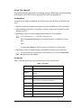
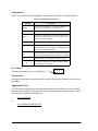
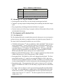
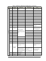
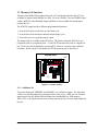
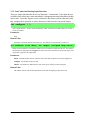
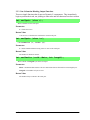
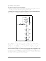
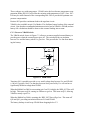
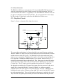
RabbitCore 2000 C-Programmable Core Module User’s Manual 001004 - C RabbitCore 2000 User’s Manual Part Number 019-0077 • 001004 - C • Printed in U.S.A. Copyright © 2000 Z-World, Inc. • All rights reserved. Z-World reserves the right to make changes and improvements to its products without providing notice. Trademarks • Dynamic C® is a registered trademark of Z-World, Inc. • Windows® is a registered trademark of Microsoft Corporation • Rabbit 2000™ is a trademark of Rabbit Semiconductor Notice to Users When a system failure may cause serious consequences, protecting life and property against such consequences with a backup system or safety device is essential. The buyer agrees that protection against consequences resulting from system failure is the buyer’s responsibility. This device is not approved for life-support or medical systems. All Z-World products are 100 percent functionally tested. Additional testing may include visual quality control inspections or mechanical defects analyzer inspections. Specifications are based on characterization of tested sample units rather than testing over temperature and voltage of each unit. Z-World may qualify components to operate within a range of parameters that is different from the manufacturer’s recommended range. This strategy is believed to be more economical and effective. Additional testing or burn-in of an individual unit is available by special arrangement. Company Address Z-World, Inc. Rabbit Semiconductor 2900 Spafford Street Davis, California 95616-6800 USA Telephone: (530) 757-3737 Facsimile: (530) 753-5141 Web site: http://www.zworld.com E-mail: [email protected] 2932 Spafford Street Davis, California 95616-6800 USA Telephone: (530) 757-8400 Facsimile: (530) 757-8402 Web site: http://www.rabbitsemiconductor.com E-mail: [email protected] RabbitCore 2000 Table of Contents About This Manual 1. Introduction1 1.1 Features .......................................................................................................................................2 1.2 Advantages of Using the RabbitCore 2000.................................................................................3 1.3 Development and Evaluation Tools ............................................................................................3 1.3.1 Development Kit........................................................................................................3 1.3.2 Documentation...........................................................................................................4 2. Subsystems......................................................................................................................5 2.1 Switching Between Program Mode and Run Mode....................................................................6 2.1.1 Detailed Instructions: Changing from Program Mode to Run Mode ........................6 2.1.2 Detailed Instructions: Changing from Run Mode to Program Mode ........................6 2.2 RabbitCore 2000 Digital Inputs and Outputs..............................................................................7 2.2.1 Dedicated Inputs ......................................................................................................10 2.2.2 Dedicated Outputs....................................................................................................10 2.3 Memory I/O Interface................................................................................................................11 2.3.1 Additional I/0 ...........................................................................................................11 2.4 Serial Communication...............................................................................................................12 2.4.1 Serial Ports ...............................................................................................................12 2.4.2 Programming Port....................................................................................................12 2.5 Clock Doubler ...........................................................................................................................13 2.6 Memory .....................................................................................................................................14 2.6.1 SRAM ......................................................................................................................14 2.6.2 Flash EPROM ..........................................................................................................14 2.6.3 Dynamic C BIOS Source Files ................................................................................14 3. Software Reference.......................................................................................................15 3.1 More About Dynamic C............................................................................................................16 3.1.1 Operating System Framework .................................................................................16 3.1.2 Using Dynamic C.....................................................................................................17 3.2 I/O..............................................................................................................................................17 3.3 Serial Communication Drivers..................................................................................................18 3.3.1 Open and Close Functions .......................................................................................19 3.3.2 Non-Cofunction Blocking Input Functions .............................................................20 3.3.3 Non-Cofunction Blocking Output Functions...........................................................21 3.3.4 Single-User Cofunction Input Functions .................................................................22 3.3.5 Single-User Cofunction Output Functions ..............................................................23 3.3.6 Circular Buffer Functions ........................................................................................24 Appendix A. Specifications ..............................................................................................27 A.1 Electrical and Mechanical Specifications.................................................................................28 A.1.1 Headers ...................................................................................................................30 A.2 Bus Loading .............................................................................................................................31 A.3 Rabbit 2000 DC Characteristics ...............................................................................................33 A.4 I/O Buffer Sourcing and Sinking Limit....................................................................................34 User’s Manual Appendix B. Prototyping Board .......................................................................................35 B.1 Mechanical Dimensions and Layout........................................................................................ 36 B.2 Power Supply ........................................................................................................................... 37 B.3 Using the Prototyping Board ................................................................................................... 37 B.3.1 Adding Other Components..................................................................................... 40 Appendix C. Power Management .....................................................................................41 C.1 Power Supplies......................................................................................................................... 42 C.1.1 Batteries and External Battery Connections........................................................... 42 C.1.2 Battery Backup Circuit ........................................................................................... 43 C.1.3 Power to VRAM Switch......................................................................................... 44 C.1.4 Reset Generator ...................................................................................................... 45 C.2 Chip Select Circuit................................................................................................................... 45 Appendix D. Sample Circuits ...........................................................................................47 D.1 D.2 D.3 D.4 D.5 RS-232/RS-485 Serial Communication................................................................................... 48 Keypad and LCD Connections ................................................................................................ 49 LCD Connections .................................................................................................................... 50 External Memory ..................................................................................................................... 51 D/A Converter.......................................................................................................................... 52 Schematics RabbitCore 2000 About This Manual This manual provides instructions for installing, testing, configuring, and interconnecting the RabbitCore 2000 (RCM 2000) and the RCM 2000 Prototyping Board. Assumptions Assumptions are made regarding the user’s knowledge and experience in the following areas: • Ability to design and engineer the target system that a RabbitCore 2000 will control. • Understanding of the basics of operating a software program and editing files under Windows on a PC. • Knowledge of basic assembly language and architecture for controllers. & For a full treatment of C, refer to the following texts: The C Programming Language by Kernighan and Ritchie (published by PrenticeHall). and/or C: A Reference Manual by Harbison and Steel (published by Prentice-Hall). • Knowledge of basic assembly language and Rabbit microprocessor architecture. & For more information on the Rabbit 2000 microprocessor, refer to the Rabbit 2000 Microprocessor user’s Guide. Acronyms Table 1 lists and defines the acronyms that may be used in this manual. Table 1. Acronyms Acronym User’s Manual Meaning EPROM Erasable Programmable Read-Only Memory EEPROM Electronically Erasable Programmable Read-Only Memory NMI Nonmaskable interrupt PIO Parallel Input/Output (Individually programmable input/output) PRT Programmable Reload Timer RAM Random Access Memory RTC Real-Time Clock SRAM Static Random Access Memory UART Universal Asynchronous Receiver Transmitter Conventions Table 2 lists and defines the typographic conventions that may be used in this manual. Table 2. Typographic Conventions Example Description while Bold Courier font indicates a program, a fragment of a program, or a Dynamic C keyword or phrase. // IN-01… Program comments are in normal Courier font. Italics Courier italics indicate that something should be typed instead of the italicized words (e.g., type a file name where filename is shown). Edit Bold sans serif font indicates a menu or menu selection. … An ellipsis indicates that (1) irrelevant program text is omitted for brevity, or that (2) the preceding program text may be repeated indefinitely. [ ] Square brackets in a C function’s definition or program segment indicate that the enclosed directive is optional. < > Angle brackets are used to enclose classes of terms. a | b | c A vertical bar indicates that a choice should be made from among the items listed. Pin Number 1 A black square indicates pin 1 of all headers. Pin 1 J1 Measurements All diagram and graphic measurements are in inches followed by millimeters enclosed in parenthesis. Application Notes The CD contains application notes and technical notes that will enhance your use of Rabbit-based products and provide information about the latest product enhancements. These notes are also available on the Web sites. www.zworld.com or www.rabbitsemiconductor.com RabbitCore 2000 1. INTRODUCTION User’s Manual 1 The RabbitCore 2000 is a microprocessor core module designed to be the heart of your own controller built around the plug-in module. Data processing is done by a Rabbit 2000 microprocessor operating at 25.8 MHz (RCM2000 and RCM2010). The RabbitCore 2000 has a Rabbit 2000 microprocessor, a static RAM, a flash memory, two quartz crystals (main oscillator and timekeeping), and the circuitry necessary for reset and management of battery backup of the Rabbit 2000’s internal real-time clock and the static RAM. Two 40-pin headers bring out the Rabbit 2000 I/O bus, address lines, data lines, parallel ports, and serial ports. The RabbitCore 2000 receives its +5 V power from the user board on which it is mounted. The RabbitCore 2000 can interface will all kinds of digital devices through the user board. The RabbitCore 2000 Development Kit comes with a Prototyping Board that can be used to demonstrate the operation of the RabbitCore 2000 and to prototype new circuits. 1.1 Features • Small size: 1.90" × 2.30" (48.3 mm × 58.4 mm) • Microprocessor: Rabbit 2000 running at 25.8 MHz (RCM2000 and RCM2010) • 40 CMOS-compatible parallel I/O lines grouped in five 8-bit ports (shared with serial ports) • 8 data lines (D0–D7) • 13 address lines (A0–A12) • I/0 read, write, buffer enable • Status, watchdog and clock outputs • Two startup mode inputs for master/slave configuration • External reset input • Reset output • Five 8-bit timers, two 10-bit timers; five timers are cascadable in pairs • 256K flash EPROM, 512K SRAM • Real-time clock • Watchdog supervisor • Provision for customer-supplied backup battery via connections on header J2 • Four CMOS-compatible serial ports: maximum asynchronous baud rate of 806,400 bps, maximum synchronous baud rate of 6.45 Mbps. Two ports are configurable as clocked ports. Appendix A, “Specifications,” provides detailed specifications for the RabbitCore 2000. Three versions of the RabbitCore 2000 are available. Their standard features are summarized in Table 1. 2 RabbitCore 2000 Table 1. RabbitCore 2000 Features Model Features RCM2000 Full-featured controller. RCM2010 RCM2000 with 128K SRAM RCM2020 RCM2000 with 18.432 MHz clock and 128K SRAM 1.2 Advantages of Using the RabbitCore 2000 • Fast design time since the basic core has already been designed and built. • Competitive pricing compared with purchasing and assembling the individual components. • Easy programming, including production installation of a program. • Generous memory size allows large C programs with tens of thousands of lines of code, and substantial data storage. 1.3 Development and Evaluation Tools 1.3.1 Development Kit The Development Kit has the essentials that you need to design your own a microprocessor-based system, and includes a complete software development system (Dynamic C). The items in the Development Kit and their use are as follows: • CD-ROM with Dynamic C® software, RabbitCore 2000, and Rabbit™ 2000 microprocessor documentation. You may install this software by inserting the disk into your CD-ROM drive. If it doesn’t start automatically, click on “setup.exe.” This software runs under Windows ‘95, Windows ‘98, and Windows NT. We suggest taking the option to load the documentation to your hard disk. The documentation is in both HTML and Adobe PDF format, and may be viewed with a browser. • RabbitCore 2000 (RCM2020 model). This is a complete controller board that includes a Rabbit 2000 processor, 256K of flash memory, 128K of SRAM. • Prototyping Board. The RabbitCore 2000 can be plugged into this board. The Prototyping Board includes a 5 V supply for powering the RabbitCore 2000, and various accessories such as pushbutton switches, and LEDs. In addition, you can add your own circuitry using through-hole or surface mount parts in the prototyping space provided. • Programming cable. The programming cable is used to connect your PC serial port directly to the RabbitCore 2000 to write and debug C programs that run on the Rabbit 2000. • AC adapter. The AC adapter is used to power the Prototyping Board and the RabbitCore 2000. The wall transformer is supplied only for Development Kits sold for the North American market. The Prototyping Board can also be powered from any DC voltage source between 7.5 V and 25 V. The linear regulator becomes rather hot for voltages above 15 V. User’s Manual 3 1.3.2 Documentation • Our documentation is provided in paperless form on the CD-ROM included in the Development Kit. (A paper copy of the “Getting Started” page is included.) Most documents, including this comprehensive RabbitCore 2000 User’s Manual, are provided in two formats: HTML and PDF. HTML documents can be viewed with an Internet browser, either Netscape Navigator or Internet Explorer. HTML documents are very convenient because all the documents are hyperlinked together, and it is easy to navigate from one place to another. PDF documents can be viewed using the Adobe Acrobat reader, which is automatically invoked from the browser. The PDF format is best suited for documents requiring high resolution, such as schematics, or if you want to print the document. Don’t print a hard copy from the HTML version because the HTML version has no page numbers and the cross-references and table of contents links only work if viewed on line. The PDF versions contain page number references to allow navigation when reading a paper version of the manual. To view the online documentation with a browser, open the file default.htm in the docs folder. 4 RabbitCore 2000 2. SUBSYSTEMS Chapter 2 describes the principal subsystems for the RabbitCore 2000. • Switching Between Program Mode and Run Mode • Rabbit 2000 Core Module Digital Inputs and Outputs • Serial Communication • Memory User’s Manual 5 2.1 Switching Between Program Mode and Run Mode The RabbitCore 2000 is automatically in Program Mode when the programming cable is attached, and is automatically in Run Mode when no programming cable is attached. See Figure 1. Run Mode RESET S2 S3 S3 J6 RS-232 C5 RXB TXB A3 A1 STAT PC1 PC3 PC5 PC7 PD1 PD3 PD5 PD7 A0 PC0 PC2 PC4 PC6 PD0 PD2 PD4 PD6 GND A5 A2 /RSTI A7 SM1 A9 A4 VCC A11 A6 C6 VRAM C4 GND RXC TXC C2 U2 A8 J4 DS3 /RSTO VCC PA1 PB3 A10 /IOR PE0 PE2 PE4 GND DS1 DS2 PB2 C3 /WDO /BEN PE1 PE6 D0 D2 D4 D6 GND /RESO S1 JP1DS2 PA0 J3 /IOW PE3 PE5 PE7 D1 D3 D5 /RSTI PWR D2 VCC C5 RN1 A12 A10 A8 A6 A4 A2 A0 PC0 PC2 U1 PC4 PC6 + PD0 C1 PD2 PD4 PD6 GND VBAT SM0 SM0 SRAM J5 J2 A9 A7 A5 A3 A1 STAT PC1 PC3 PC5 PC7 PD1 PD3 PD5 PD7 VCC VRAM SM1 JP1 U2 R4 PB7 J3A11 TP3 A12 C2 R2 TP2 S2 DS3 C3 D7 Y2 PB5 PB1 PA5 PA7 PA6 PA4 PB2 PB0 PA1 VCC PA3 PA2 PA0 GND /RSTI SM1 VRAM VCC GND VCC SM0 GND VBAT J2 PB3 R3 PB6 /WDO Y1 C1 GND PA0 PA2 R1 PA4 U1 PA6 PB0 PB2 PB4 PB6 PCLK D7 D5 D3 D1 PE7 PE5 PE3 PE1C4 /IOW /BEN PCLK J1 PA1 PA3 PA5 PA7 PB1 PB3 PB5 PB7 GND D6 D4 D2 D0 PE6 PE4 PE2 PE0 /IOR PB4 TXB RCM2000 PROTOTYPING BOARD RESET S2 RXC TXC RXB /RSTO PD5 PD3 PD7 PD6 PD1 PC7 Pins 3840 To PC COM port GND VCC J1 C6 PD4 PC5 PC3 PC1 C5 PD2 C4 PC4 STAT J6 RS-232 PC2 A1 A3 S3 S3 C2 U2 PC0 A5 DS3 S2 DS3 PA1 PB3 A0 A7 A9 DS1 DS2 PB2 A2 A4 A6 A11 J4 A10 /IOR PE0 VCC S1 JP1DS2 PA0 C3 /WDO /BEN PE2 PE4 PE6 D0 D2 D4 D6 GND /RESO GND D2 J3 /IOW PE1 PE3 PE5 PE7 D1 D3 Colored side lines up with pin 1 /RSTI PWR PD0 C5 TP1 RN1 A12 A10 A8 A6 A4 A2 A0 PC0 PC2 U1 PC4 PC6 + PD0 C1 PD2 PD4 PD6 GND VBAT SM0 PC6 SRAM J5 J2 A9 A7 A5 A3 A1 STAT PC1 PC3 PC5 PC7 PD1 PD3 PD5 PD7 VCC VRAM SM1 JP1 R4 PB7 J3A11 TP3 A12 TP2 U2 D5 PB5 C2 R2 D7 PB3 Y2 PB6 PB1 PA7 PA6 PB2 PB0 PA3 PA1 PA5 PA4 PA2 GND J2 PA0 VCC R3 C3 PCLK /WDO Y1 C1 GND PA0 PA2 R1 PA4 U1 PA6 PB0 PB2 PB4 PB6 PCLK D7 D5 D3 D1 PE7 PE5 PE3 PE1C4 /IOW /BEN PB4 RCM2000 PROTOTYPING BOARD J1 PA1 PA3 PA5 PA7 PB1 PB3 PB5 PB7 GND D6 D4 D2 D0 PE6 PE4 PE2 PE0 /IOR A8 TP1 VCC J1 Power Rabbit 2000 Core Module GND Power Rabbit 2000 Core Module VBAT Program Mode RESET Core Module when changing mode: Short out pins 3840 on header J2, OR Press RESET button (if using Prototyping Board), OR Remove, then reapply power after removing or attaching programming cable. Figure 1. RabbitCore 2000 Program Mode and Run Mode Setup 2.1.1 Detailed Instructions: Changing from Program Mode to Run Mode 1. Disconnect the programming cable from header J3 of the RabbitCore 2000. D2 3. Attach the programming cable to header J3 on the RabbitCore 2000. DS1 DS2 PA1 S2 JP1DS2 PA0 PB2 2.1.2 Detailed Instructions: Changing from Run Mode to Program Mode S1 RESET PWR DS3 S3 The RabbitCore 2000 is now ready to operate in the Run Mode. J5 RN1 S2 DS3 2. Reset the RabbitCore 2000. You may do this as explained in Figure 1. Figure 2 shows the location of the RESET button on the Prototyping Board. PB3 Figure 2. Location of Prototyping Board Reset Button 4. Reset the RabbitCore 2000. You may do this as explained in Figure 1. Figure 2 shows the location of the RESET button on the Prototyping Board. The RabbitCore 2000 is now ready to operate in the Program Mode. 6 RabbitCore 2000 2.2 RabbitCore 2000 Digital Inputs and Outputs Figure 3 shows the subsystems designed into the RabbitCore 2000. PA0PA7 4x CMOS synchronous/ asynchronous PCLK RESET WDO PB0 PB5 PB6 PB7 PD0PD7 Port A Port B Port D Serial Ports (Port C) RABBIT 2000 CORE MODULE Port E PE0PE7 Address Lines A0A12 I/O Control IORD IOWR BUFEN Programming Port Misc. Outputs Real-Time Clock Watchdog 7 Timers Slave Port Clock Doubler RAM Backup Battery Support Data Lines DA0DA7 Flash Figure 3. RabbitCore 2000 Subsystems The RabbitCore 2000 has 40 parallel I/O lines grouped in five 8-bit ports available on headers J1 and J2. The 24 bidirectional I/O lines are located on pins PA0–PA7, PD0-PD7, and PE0-PE7. The pinouts for headers J1 and J2 are shown in Figure 4. J2 A12 A10 A8 A6 A4 A2 A0 PC0 PC2 PC4 PC6 PD0 PD2 PD4 PD6 GND VBAT SMODE0 /RES_OUT VCC J1 A11 A9 A7 A5 A3 A1 STATUS PC1 PC3 PC5 PC7 PD1 PD3 PD5 PD7 VCC VRAM SMODE1 /RES_IN GND GND PA0 PA2 PA4 PA6 PB0 PB2 PB4 PB6 PCLK D7 D5 D3 D1 PE7 PE5 PE3 PE1 /IOWR /BUFEN VCC PA1 PA3 PA5 PA7 PB1 PB3 PB5 PB7 GND D6 D4 D2 D0 PE6 PE4 PE2 PE0 /IORD /WDO Note: These are the pinouts as seen on the Bottom Side of the Core Module. Figure 4. RabbitCore 2000 I/O Pins User’s Manual 7 The ports on the Rabbit 2000 microprocessor used in the RabbitCore 2000 are configurable, and so the factory defaults can be reconfigured. Table 2 lists the Rabbit 2000 factory defaults and the alternate configurations. Table 2. RabbitCore 2000 Pinout Configurations Pin Pin Name 1, 20 GND 2 VCC Default Use Alternate Use PA[0:7] Parallel I/O Slave port data bus SD0–SD7 11 PB0 Input Serial port clock CLKB 12 PB1 Input Serial port clock CLKA 13 PB2 Input Slave port write /SWR 14 PB3 Input Slave port read /SRD 15 PB4 Input SA0 16 PB5 Input SA1 17 PB6 Output 18 PB7 Output Slave port attention line /SLAVEATTN 19 PCLK Output (Internal Clock) Output 21–28 D[7:0] Input/Output 3–10 Notes CLKA is connected to programming port (header J3, pin 3) Header J1 Slave port address lines 8 Rabbit 2000 data bus 29 PE7 I7 output or slave port chip select /SCS 30 PE6 I6 output 31 PE5 I5 output or INT1B input 32 PE4 33 PE3 I3 output 34 PE2 I2 output 35 PE1 I1 output or INT1A input 36 PE0 I0 output or INT0A input 37 /IOWR Output (I/O write strobe) 38 /IORD Output (I/O read strobe) 39 /BUFEN Output (I/O buffer enable) 40 /WDO Output (Watchdog output) Bitwise or parallel programmable I/O Disable by removing R27 I4 output or INT0B input May also be used to output a 30 µs pulse Outputs a pulse when the internal watchdog times out RabbitCore 2000 Table 2. RabbitCore 2000 Pinout Configurations (continued) Header J2 Pin Pin Name Default Use Alternate Use Output Notes Rabbit 2000 address bus 1–13 A[12:0] 14 STAT Output (Status) Output 15 PC0 Output TXD 16 PC1 Input RXD 17 PC2 Output TXC 18 PC3 Input RXC 19 PC4 Output TXB 20 PC5 Input RXB 21 PC6 Output TXA 22 PC7 Input RXA 21 PC6 Output TXA 22 PC7 Input RXA 23–26 PD[0:3] 27 PD4 28 PD5 29 PD6 ATXA output 30 PD7 ARXA input 31, 40 GND 32, 39 VCC 33 VBATR 3 V battery input 34 VRAM 2.1 V output 100 kΩ minimum load (0,0)—start executing at address zero No programming cable attached 35–36 SMODE0, SMODE1 37 /RES_OUT 38 /RES_IN User’s Manual Connected to programming port 16 mA sourcing and sinking current at full AC switching speed Bitwise or parallel programmable I/O, can be driven or open-drain output ATXB output ARXB input SMODE0 =1, SMODE1 = 1 (0,1)—cold boot from Cold boot from asynslave port chronous serial port A at (1,0)—cold boot from 2400 bps (programming clocked serial port A cable connected) With programming cable attached Reset Output Reset Input 9 As shown in Table 2, pins PA0–PA7 can be used to allow the Rabbit 2000 to be a slave to another processor. PE0, PE1, PE4, and PE5 can be used as external interrupts INT0A, INT1A, INT0B, and INT1B. Pins PB0 and PB1 can be used to access the clock on Serial Port B and Serial Port A of the Rabbit microprocessor. Pins PD4 and PD6 can be programmed to be optional serial outputs for Serial Ports B and A. PD5 and PD7 can be used as alternate serial inputs by Serial Ports B and A. 2.2.1 Dedicated Inputs PB0 and PB1 are designated as inputs because the Rabbit 2000 is operating in an asynchronous mode. Four of the input-only pins are located on PB2–PB5. These pins are used for the slave port. PB2 and PB3 are slave write and slave read strobes, while PB4 and PB5 serve as slave address lines SA0 and SA1, and are used to access the slave registers (SD0– SD7), which is the alternate assignment for parallel port A. When Port C is used as a parallel port, PC1, PC3, PC5, and PC7 are inputs only. These pins can alternately be selectively enabled to serve as the serial data inputs for Serial Ports D, C, B, and A. 2.2.2 Dedicated Outputs Two of the output-only pins are located on PB6–PB7. PB7 can also be used with the slave port as the /SLAVEATTN output. This configuration signifies that the slave is requesting attention from the master. When Port C is used as a parallel port, PC0, PC2, PC4 and PC6 are outputs only. These pins can alternately serve as the serial data outputs for Serial Ports D, C, B, and A. 10 RabbitCore 2000 2.3 Memory I/O Interface Thirteen of the Rabbit 2000 address lines (A0–A12) and all the data lines (D0–D7) are available as outputs on the RabbitCore 2000. I/0 write (/IOWR), I/0 read (/IORD), buffer enable (/BUFEN), and Watchdog Output (/WDO) are also available for interfacing to external devices. The STATUS output has three different programmable functions: 1. It can be driven low on the first op code fetch cycle. 2. It can be driven low during an interrupt acknowledge cycle. 3. It can also serve as a general-purpose output. The output clock is available on the PCLK pin. The primary function of PCLK is as a peripheral clock or a peripheral clock ÷ 2, but PCLK can instead be used as a digital output. PCLK can also be disabled by removing R27 if there is a need to reduce radiated emissions. Removing R27 will disable the PCLK output on pin 19 of header J1. Bottom Side R10 Q10 Q11 D10 D11 D12 R11 R12 R13 A1 R30 A0 STAT PC0 PC1 Q13 R28 R31 R32 PC3 PC4 PC5 PC6 PC7 C14 PC2 GND VCC VBAT VRAM /RSTI VCC GND R36 C18 SM1 C17 SM0 /RESO C16 R42 R41 R40 PD7 J1 VCC PA0 PA1 PA2 PA3 PA4 PA5 PA6 PA7 PB0 PB1 PB2 PB3 PB4 PB5 PB6 PB7 PCLK GND D7 D6 D5 D4 D3 R38 PD6 Flash EPROM R39 PD5 R27 C13 R37 PD4 U10 PD3 C15 PD1 PD2 R34 R35 PD0 R33 C12 U11 R26 A3 R29 A2 R17 R18 JP2 R25 A5 A4 R16 C11 A6 GND R15 R24 A7 R23 R22 R21 A9 A8 C10 A11 A10 Q14 Q15 D13 A12 R27 R14 R19 R20 Q12 D2 D1 D0 PE7 PE6 PE5 PE4 PE3 PE2 PE1 PE0 /IOW /IOR /BEN /WDO Figure 5. Location of R27 2.3.1 Additional I/0 Two status mode pins, SMODE0 and SMODE1, are available as inputs. The logic state of these two pins determines the startup procedure after a reset. /RES_IN is an external input used to reset the Rabbit 2000 microprocessor and RabbitCore 2000 memory. /RES_OUT is an output from the reset circuitry that can be used to reset other peripheral devices. User’s Manual 11 2.4 Serial Communication The RabbitCore 2000 does not have an RS-232 or an RS-485 transceiver directly on the RabbitCore 2000 board. However, the Prototyping Board does support a industry standard RS-232 transceiver chip. See Appendix B, “Prototyping Board,” for more information. 2.4.1 Serial Ports There are four serial ports designated as Serial Ports A, B, C, and D. All four serial ports can operate in an asynchronous mode up to the baud rate of the system clock divided by 32. An asynchronous port can handle 7 or 8 data bits. A 9th bit address scheme, where an additional bit is sent to mark the first byte of a message, is also supported. Serial ports A and B can be operated alternately in the clocked serial mode. In this mode, a clock line synchronously clocks the data in or out. Either of the two communicating devices can supply the clock. When the Rabbit provides the clock, the baud rate can be up to 1/4 of the system clock frequency, or more than 6.45 Mbps for a 25.8 MHz clock speed. 2.4.2 Programming Port Serial Port A has special features that allow it to cold-boot the system after reset. Serial Port A is also the port that is used for software development under Dynamic C. The RabbitCore 2000 has a 10-pin program header labeled J3. The Rabbit 2000 startupmode pins (SMODE0, SMODE1) are presented to the programming port so that an externally connected device can force the RabbitCore 2000 to start up in an external bootstrap mode. The Rabbit 2000 Microprocessor User’s Manual provides more information related to the bootstrap mode. The programming port is used to start the RabbitCore 2000 in a mode where it will download a program from the port and then execute the program. The programming port transmits information to and from a PC while a program is being debugged. The RabbitCore 2000 can be reset from the programming port via the /RESET_IN line. The Rabbit 2000 status pin is also presented to the programming port. The status pin is an output that can be used to send a general digital signal. The clock line for Serial Port A is presented to the programming port, which makes fast serial communication possible. 12 RabbitCore 2000 2.5 Clock Doubler The RabbitCore 2000 takes advantage of the Rabbit 2000 microprocessor’s internal clock doubler. A built-in clock doubler allows half-frequency crystals to be used to reduce radiated emissions. The 25.8 MHz (RCM 2000 and RCM2010) and 18.4 MHz (RCM 2020) frequencies are generated using 12.9 MHz and 9.2 MHz crystals. The clock doubler is disabled automatically in the BIOS for crystals with a frequency above 12.9 MHz. The clock doubler can be disabled if 25.8 MHz or 18.4 MHz clock speeds are not required. Disabling the Rabbit 2000 microprocessor’s internal clock will reduce power consumption and further reduce radiated emissions. The clock doubler is disabled with a simple change to the BIOS as described below. 1. Open the BIOS source code file, RABBITBIOS.C in the BIOS directory. 2. Change the line #define CLOCK_DOUBLED 1 // set to 1 to double the clock if XTAL<=12.9MHz, to read as follows. #define CLOCK_DOUBLED 0 // set to 1 to double the clock if XTAL<=12.9MHz, 3. Change the serial baud rate to 57,600 bps when the RabbitCore 2000 is operated at 12.9 MHz or 9.2 MHz. 4. Save the change using File > Save. User’s Manual 13 2.6 Memory 2.6.1 SRAM The RabbitCore 2000 is designed to accept 32K to 512K of SRAM packaged in an SOIC case. The existing standard models of the RabbitCore 2000 come with 128K or 512K of SRAM. Figure 6 shows the locations and the jumper settings for the jumpers at JP1 used to set the SRAM size. The “jumpers” are 0 Ω surface-mounted resistors. SRAM 128K JP1 Flash EPROM 512K JP1 3 2 1 TP1 C1 3 2 1 C2 JP1 R12 R13 A7 A6 A5 A4 A3 R29 A2 A1 R30 A0 STAT PC0 PC1 R16 R28 R31 PC2 R32 PC3 PC4 PC5 PC6 PC7 PD1 PD2 PD3 PD4 PD5 PD6 PD7 GND VCC VBAT VRAM /RSTI VCC GND R27 C13 R36 R14 J1 VCC PA0 PA1 PA2 PA3 PA4 PA5 PA6 PA7 PB0 PB1 PB2 PB3 PB4 Flash EPROM PB5 PB6 PB7 PCLK GND D7 D6 D5 D4 D3 C18 SM1 C12 U11 C17 SM0 /RESO JP2 C16 R42 R41 R40 PD0 R33 R17 R18 R26 A8 R15 R25 A9 C11 A10 GND R24 A11 R38 VCC R11 R39 GND R4 D12 R37 /RESO A12 U10 /RSTI D11 R19 R20 Q12 C15 C5 D10 R23 R22 R21 SRAM A12 A10 A8 A6 A4 A2 A0 PC0 PC2 PC4 PC6 PD0 PD2 PD4 PD6 GND VBAT SM0 Q11 Q14 Q15 D13 U2 TP3 A11 A9 A7 A5 A3 A1 STAT PC1 PC3 PC5 PC7 PD1 PD3 PD5 PD7 VCC VRAM SM1 Q10 3 2 1 C10 R2 TP2 J2 Q13 Y2 C3 512K JP2 R10 Y1 GND PA0 PA2 R1 PA4 U1 PA6 PB0 PB2 PB4 PB6 PCLK D7 D5 D3 D1 PE7 PE5 PE3 PE1C4 /IOW /BEN R3 3 2 1 R34 R35 /WDO JP2 C14 VCC PA1 PA3 PA5 PA7 PB1 PB3 PB5 PB7 GND D6 D4 D2 D0 PE6 PE4 PE2 PE0 /IOR J1 128K/256K D2 D1 D0 PE7 PE6 PE5 PE4 PE3 PE2 PE1 PE0 /IOW /IOR /BEN /WDO J3 Top Side Bottom Side Figure 6. RabbitCore 2000 Jumper Settings for SRAM and Flash EPROM Size 2.6.2 Flash EPROM The RabbitCore 2000 is also designed to accept 128K to 512K of flash EPROM packaged in a TSOP case. The existing standard models of the RabbitCore 2000 come with 256K of flash EPROM. Figure 6 shows the locations and the jumper settings for the jumpers at JP2 used to set the flash EPROM size. The “jumpers” are 0 Ω surface-mounted resistors. ! Z-World recommends that any customer applications should not be constrained by the sector size of the flash EPROM since it may be necessary to change the sector size in the future. 2.6.3 Dynamic C BIOS Source Files The Dynamic C BIOS source files handle different standard RAM and flash EPROM sizes automatically. 14 RabbitCore 2000 3. SOFTWARE REFERENCE User’s Manual 15 3.1 More About Dynamic C Dynamic C has been in use worldwide since 1989. Dynamic C is specially designed for programming embedded systems. Dynamic C features quick compile and interactive debugging in the real environment. A complete reference to Dynamic C is contained in the Dynamic C Reference Manual. Dynamic C for Rabbit™ processors uses the standard Rabbit programming interface. This is a 10-pin connector that connects to the Rabbit serial port A. It is possible to reset and cold-boot a Rabbit processor via the programming port. No software needs to be present in the target system. More details are available in the Rabbit 2000 Microprocessor User’s Manual. Dynamic C cold-boots the target system and compiles the BIOS. The BIOS is a basic program of a few thousand bytes in length that provides the debugging and communication facilities that Dynamic C needs. Once the BIOS has been compiled, the user can compile his own program and test it. If the BIOS fails because the program stops running, a new cold boot and BIOS compile can be done at any time. The BIOS can be customized by using #define options. Dynamic C does not use include files, rather it has libraries that are used for the same purpose, that is, to supply function prototypes to programs before they are compiled. Libraries are much easier to use compared to include files. Dynamic C supports assembly language, either as separate functions or as fragments embedded in C programs. Interrupt routines may be written in Dynamic C or in assembly language. 3.1.1 Operating System Framework Dynamic C does not include an operating system in the usual sense of a complex software system that is resident in memory. The user has complete control of what is loaded as a part of his program, other than those routines that support loading and debugging (which are inactive at embedded run time). However, certain routines are very basic and normally should always be present and active. • Periodic interrupt routine. This interrupt routine is driven by the Rabbit periodic interrupt facility, and when enabled creates an interrupt every 16 ticks of the 32.768 kHz oscillator, or every 488 µs. This routine drives three long global variables that keep track of the time: SEC_TIMER, MS_TIMER, and TICK_TIMER that respectively count seconds, milliseconds, and 488 µs ticks. These variables are needed by virtually all functions that measure time. The SEC_TIMER is set to seconds elapsed since 1 Jan 1980, and thus also keeps track of the time and date. The periodic interrupt routine must be disabled when the microprocessor enters sleepy mode and the processor clock is operating at 32.768 kHz. The interrupt routine cannot complete at this slow speed before the next tick of the periodic interrupt. In this situation, the hardware real-time clock can be read directly to provide the time. 16 RabbitCore 2000 • Watchdog support routines. Although the Rabbit watchdog can be disabled, this is not recommended since the watchdog is an essential facility for recovering when a program stops running. Very few systems are crash-free in real life. 3.1.2 Using Dynamic C You have a choice of doing your software development in the flash memory or in the static RAM. There are 256K bytes of flash and 128K SRAM memory. The advantage of working in RAM is to save wear on the flash, which is limited to about 100,000 writes. ! Note that an application can be developed in RAM, but cannot run standalone from RAM after the programming cable is disconnected. All applications can only run from flash. Do not depend on the flash sector size for debugging. Due to the volatility of the flash market, the RabbitCore 2000 and Dynamic C were designed to accommodate flash devices with various sector sizes. When using flash EPROM, the compile to a file is followed by a download to the flash EPROM. The disadvantage of using flash EPROM is that interrupts must be disabled for approximately 5 ms whenever a break point is set in the program. This can crash fast interrupt routines that are running while you stop at a break point or single-step the program. Flash EPROM or RAM is selected with the Dynamic C Options > Compiler menu. 3.2 I/O The RabbitCore 2000 was designed to interface with other systems, and so there are no drivers written specifically for this purpose. The general Dynamic C read and write functions allow you to customize the parallel I/O to meet your specific needs. For example, use WrPortI(PEDDR, &PEDDRShadow, 0x00); to set all the port E bits as inputs, or use WrPortI(PEDDR, &PEDDRShadow, 0xFF); to set all the port E bits as outputs. The sample programs in the Dynamic C SAMPLES directory provide further examples. User’s Manual 17 3.3 Serial Communication Drivers The Prototyping Board has room for an RS-232 chip for which the Rabbit serial library, RSERIAL.LIB, provides users with a set of functions that send and receive entire blocks of data without yielding to other tasks, a set of single-user cofunctions that send and receive data but yield to other tasks, and a set of circular buffer functions. The naming convention is serXfn: ser - serial X - the port being used: A, B, C, or D fn - the function being implemented For example, serBgetc() is the serial port B function getc(), which returns a character. The Rabbit serial functions are listed in the following groups. Open and Close Functions Non-Cofunction Blocking Input Functions Non-Cofunction Blocking Output Functions Single-User Cofunction Input Functions Single-User Cofunction Output Functions Circular Buffer Functions 18 RabbitCore 2000 3.3.1 Open and Close Functions The open and close functions enable and disable serial communication over the specified port. int serXopen (long baud); Currently only 8N1 transmission (8 data bits, no parity, 1 stop bit) is supported. The open function sets up the interrupt service routine vector. Parameters baud—desired baud rate in bits per second Return Value 1—The baud rate set on the Rabbit is the same as the input baud rate. 0—The baud rate set on the rabbit does not match the input baud rate. int serXclose ( ); Disables the serial port interrupt service routine. Parameters None. Return Value 1 User’s Manual 19 3.3.2 Non-Cofunction Blocking Input Functions These are simple functions that do not use Dynamic C costatements. If no input data are available when called, they return immediately with appropriate status information in their return value. Once they begin to receive characters, they do not yield to other tasks until they complete their operation or until a character-to-character time-out period elapses. int serXgetc ( ); Gets a single character. Always returns immediately, either with the next available input byte, or with –1 if none is available. Parameters None Return Value An integer with return character in the low byte. No character is represented by a return of –1. int serXread (void *data, int length, unsigned long tmout); Reads a block of characters. Returns the number of bytes read from an input serial stream. The stream is considered to be ended when all length bytes have been read or when the timeout period elapses waiting for data to appear in the input buffer. Parameters data—Destination data structure. The user must ensure data is allocated for at least length bytes. length—The number of bytes to read. tmout—The number of milliseconds to wait for receipt of each byte before timing out. Return Value The number of bytes read into data until timed out or until all length bytes have been read. 20 RabbitCore 2000 3.3.3 Non-Cofunction Blocking Output Functions These are simple functions that do not use Dynamic C costatements. They immediately begin to perform their task, not yielding to other tasks until all characters have been written. int serXputc (char c); Writes a character to the serial port. Parameters c—Character to write Return Value 1 for success, 0 if the character could not be written to the port. int serXputs (char *s); Calls serXwrite (s, strlen (s)). Parameters s—Null-terminated character string source to write to the serial port. Return Value The number of characters written. int serXwrite (void *data, int length); Writes a block of length bytes to the serial port. Parameters data—Destination data structure. The user must ensure data is allocated for at least length bytes. length—The number of bytes to read. Return Value The number of bytes written to the serial port. User’s Manual 21 3.3.4 Single-User Cofunction Input Functions These are Dynamic C cofunctions. If the input buffer they use is locked or becomes full during the course of their operation, they yield to other tasks, but do not return to execute the next statement within their own costatement block until they have completed their operation. scofunc int cof_serXgetc ( ); Reads a single character from the serial port, yielding when not successful, and only returning when a character is successfully read. Parameters None Return Value An integer with the character read in the low byte. scofunc int cof_serXgets(char *s, int length, unsigned long tmout); Reads a null-terminated string, completes its execution when a carriage return is read, length number of characters are read, or the character to character time-out period elapses after the first character is read. It yields to other tasks while the input buffer is locked or becomes empty during its execution, and only returns control to the following statement in its own costatement block when it completes. Parameters data—Destination data structure. The user must ensure data is allocated for at least length bytes. length—The number of bytes to read. tmout—The number of milliseconds to wait for each character after the first character is read. Return Value 1—CR or length bytes read into s. 0—Function times out before reading CR or length bytes. scofunc int cof_serXread(void *data, int length, unsigned long tmout); Reads a block of characters, completes its execution when length number of characters are read, or the character-to-character time-out period elapses after the first character is read. It yields to other tasks while the input buffer is locked or becomes empty during its execution and only returns control to the following statement in its own costatement block when it completes. Parameters data—Destination data structure. The user must ensure data is allocated for at least length bytes. length—The number of bytes to read. tmout—The number of milliseconds to wait for each character after the first. Return Value The number of bytes read. 22 RabbitCore 2000 3.3.5 Single-User Cofunction Output Functions These are Dynamic C cofunctions. If the output buffer they use is locked or becomes empty during the course of their operation, they yield to other tasks, but do not return to execute the next statement within their own costatement block until they have completed their operation. scofunc void cof_serXputc (char c); Writes a single character to the serial port, yielding to other tasks when unsuccessful, and returning only when the character is successfully written. Parameters c—Character to write to the serial port. Return Value None scofunc void cof_serXputs(char *s); Writes a null-terminated character string to the serial port, yielding to other tasks when unsuccessful or whenever the buffer is full, returning only when the string is successfully written. Parameters s—Null-terminated character string written to the serial port. Return Value None scofunc void cof_serXwrite (void *data, int length); Writes a block of characters to the serial port, yielding to other tasks when unsuccessful or whenever the buffer is full, returning only when all the data is successfully written. Parameters data—Source data structure to write to the serial port. length—Number of characters in data to write. Return Value None User’s Manual 23 3.3.6 Circular Buffer Functions These functions act on or report status of the circular transmit/receive buffers. Macro definitions are used to establish the buffer sizes: xINBUFSIZE—read buffer size, where x is A, B, C, or D xOUTBUFSIZE—write buffer size where x is A, B, C, or D The user must define each buffer size for each port being used to be a power of 2 minus 1 with a macro. The size of 2^n - 1 enables masking for fast rollover calculations. If no value or an illegal value is defined, a default size of 31 will be used and a compiler warning will be given. When using cofunctions, smaller buffer sizes can yield more frequently to other tasks, but have the risk of a large input data stream overrunning the buffer and losing data if the other task executes for too long relative to the baud rate. int serXpeek ( ); Returns the first character in the receive buffer, if any are available, without removing it from the buffer. Parameters None Return Value An integer with return character in the low byte. No character is represented by a return of –1. void serXrdFlush ( ); Flushes the serial port receive buffer. Parameters None Return Value None void serXwrFlush ( ); Flushes the serial port transmit buffer. Parameters None Return Value None 24 RabbitCore 2000 int serXrdFree ( ); Calculates the free space in the serial port receive buffer. Parameters None Return Value The number of characters the serial port receive buffer can accept before becoming full. int serXwrFree ( ); Calculates the free space in the serial port transmit buffer. Parameters None Return Value The number of characters the serial port transmit buffer can accept before becoming full. int serXrdUsed ( ); Calculates the number of characters ready to read from the serial port receive buffer. Parameters None Return Value The number of characters currently in the serial port receive buffer. User’s Manual 25 26 RabbitCore 2000 APPENDIX A. SPECIFICATIONS User’s Manual 27 A.1 Electrical and Mechanical Specifications Figure A-1 shows the mechanical dimensions for the RabbitCore 2000. 2.30 (58.4) 1.31 (33.3) JP1 SRAM C5 R4 /RESO GND VCC J3 0.50 0.50 (14) (13) 0.31 (5.0) (3.2) (6.9) 0.125 dia 0.31 (9.42) Y2 /RSTI 1.90 U2 A12 A10 A8 A6 A4 A2 A0 PC0 PC2 PC4 PC6 PD0 PD2 PD4 PD6 GND VBAT SM0 (48.3) C2 R2 J2 A11 A9 A7 A5 A3 A1 STAT PC1 PC3 PC5 PC7 PD1 PD3 PD5 PD7 VCC VRAM SM1 0.27 R1 TP3 0.27 U1 R3 (0,0) for Pin 1 coordinates C3 TP2 0.371 /WDO Y1 C1 GND PA0 PA2 PA4 PA6 PB0 PB2 PB4 PB6 PCLK D7 D5 D3 D1 PE7 PE5 PE3 PE1C4 /IOW /BEN 0.20 J1 0.20 TP1 VCC PA1 PA3 PA5 PA7 PB1 PB3 PB5 PB7 GND D6 D4 D2 D0 PE6 PE4 PE2 PE0 /IOR 2.30 (13) (14) (6.9) (5.0) (58.4) 1.90 (48.3) Figure A-1. RabbitCore 2000 Dimensions Table A-1 provides the pin 1 locations for the RabbitCore 2000 headers viewed from the top side (as in Figure A-1). Table A-1. Jackrabbit Header Pin 1 Locations 28 Header Description Pin 1 (x,y) Coordinates (Inches) J1 RabbitCore 2000 subsystems (0.221, 1.675) J2 RabbitCore 2000 subsystems (2.181, 1.675) J3 Programming port (1.600, 0.214) RabbitCore 2000 Table A-2 lists the electrical, mechanical, and environmental specifications for the RabbitCore 2000. Table A-2. RCM2000 Specifications Parameter Specification Board Size 1.90" × 2.30" × 0.50" (48.3 mm × 58.4 mm × 12.7 mm) Operating Temperature –40°C to +85°C Storage Temperature –55°C to +125°C Humidity 5% to 95%, noncondensing Input Voltage 4.75 V to 5.25 V DC Current 58 mA at 9.216 MHz, 5 V DC 74 mA at 12.9024 MHz, 5 V DC 98 mA at 18.432 MHz, 5 V DC 130 mA at 25.8048 MHz, 5 V DC Standby Current 16 µA (typical), 50 µA (maximum) General-Purpose I/O 40 parallel I/0 lines grouped in five 8-bit ports: 24 bidirectional, 10 inputs only, 6 outputs only Memory, I/O Interface 13 address lines, 8 data lines, I/O read/write, buffer enable, status, clock Additional Digital Inputs 2 startup mode (for master/slave), reset in Additional Digital Outputs Watchdog output, reset out Microprocessor Rabbit 2000 Clock 25.8048 MHz (18.432 MHz option) SRAM 512K (supports 32K–512K) Flash EPROM 256K (supports 128K–512K) Timers Five 8-bit timers cascadable in pairs, one 10-bit timer with 2 match registers that each have an interrupt Serial Ports Four CMOS-compatible ports. Two ports are configurable as clocked ports, one is configurable as RS-232 programming port. Serial Rate CMOS maximum asynchronous 806,400 bps maximum synchronous 6.45 Mbps Watchdog/Supervisor Yes Time/Date Clock Yes User’s Manual 29 Table A-2. RCM2000 Specifications (continued) Parameter Specification Socket Strip (for connection Pinrex 2x20, 2 mm pitch (PS2S-2X20GOB) to headers J1 and J2) Recommended Standoff (to attach RabbitCore 2000 9/32” (7.14) with 4-40 screw to user board) Provision for user-supplied backup battery (2.85 V to 3.15 V) via connections on header J2 Backup Battery A.1.1 Headers The RabbitCore 2000 uses headers at J1, J2, and J3 for physical connection to other boards. J1 and J2 are 2 × 20 SMT headers with a 2 mm pin spacing. J3 is a 2 × 5 header with a 2 mm pin spacing. Figure A-2 shows the layout of another board for the RabbitCore 2000 to be plugged in to. These values are relative to the header connectors. 1.960 J1 (49.78) 1.094 J2 (27.79) 0.020 sq typ (0.5) 0.079 (2.0) 1.30 (33.0) 0.079 (2.0) 0.125 dia (3.2) Figure A-2. J1 and J2 Header Layout (Top View) 30 RabbitCore 2000 A.2 Bus Loading When designing an interface to the RabbitCore 2000, careful attention must be paid to bus loading. This section provides bus loading of external devices. Table A-3 lists the capacitance for the various RabbitCore 2000 I/O ports. Table A-3. Capacitance of Rabbit 2000 I/O Ports Input Capacitance (pF) Output Capacitance (pF) Parallel Ports A to E 12 14 Data Lines D0–D7 30 32 Address Lines A0–A12 30 32 I/O Ports Table A-4 lists the external capacitive bus loading for the various Rabbit 2000 output ports. Be sure to add the loads for the devices you are using in your custom system and verify that they do not exceed the values in Table A-4. Table A-4. External Capacitive Bus Loading -40°C to +85°C Clock Speed (MHz) Maximum External Capacitive Loading (pF) A[12:1] D[7:1] 25.8 50 A[12:1] D[7:1] 18.4 55 for 90 ns flash 100 for 55 ns flash* A0 D0 25.8, 18.4 100 PD[3:0] 25.8, 18.4, 100 PA[7:0] PB[7,6,1,0] PC[6,4,2,0] PD[7:4] PE[7:0] 25.8, 18.4 90 All data, address, and I/O lines with clock doubler disabled 12.9, 9.2 100 Output Port * The RCM2020 operating at 18.4 MHz will typically come with a flash EPROM whose access time is 55 ns. Because of the volatility of the memory market, a 90 ns flash EPROM could be used on the RCM2020. User’s Manual 31 The values from the table above are derived using 55 ns (25.8 MHz version) and 90 ns (18.4 MHz version) memory access times. External capacitive loading can be improved by 10 pF for commercial temperature ranges, but do not exceed 100 pF. See the AC timing specifications in the Rabbit 2000 Users Manual for more information. Figure A-3 shows a typical timing diagram for the Rabbit 2000 microprocessor memory read and write cycles. Memory Read (no wait states) T2 T1 CLK A[19:0] valid Tadr Tsetup D[7:0] valid Thold /CSx valid /OEx Memory Write (no extra wait states) Tw T1 T2 CLK A[19:0] valid Tadr D[7:0] /CSx valid /WE valid Thold /WEx Figure A-3. Memory Read and Write Cycles Tadr is the time required for the address output to reach 0.8 V. This time depends on the bus loading. A0 has a stronger driver and can handle larger capacitive loads than the other address lines. Tsetup is the data setup time relative to the clock. Tsetup is specified from 30%/70% of the VDD voltage level. Add 1.5 ns to Tadr for each 10 pF of additional bus loading above 70 pF. 32 RabbitCore 2000 A.3 Rabbit 2000 DC Characteristics Table A-5 outlines the DC characteristics for the Rabbit 2000 at 5.0 V over the recommended operating temperature range from Ta = –40°C to +85°C, VDD = 4.5 V to 5.5 V. Table A-5. 5.0 Volt DC Characteristics Symbol Parameter Test Conditions Min IIH Input Leakage High VIN = VDD, VDD = 5.5 V IIL Input Leakage Low (no pull-up) VIN = VSS, VDD = 5.5 V -10 IOZ Output Leakage (no pull-up) VIN = VDD or VSS, VDD = 5.5 V -10 VIL CMOS Input Low Voltage VIH CMOS Input High Voltage VT CMOS Switching Threshold VDD = 5.0 V, 25°C VOL CMOS Output Low Voltage VOH IOH = See Table A-6 CMOS Output High Voltage (sourcing) VDD = 4.5 V User’s Manual Typ Max Units 10 µA µA 10 µA 0.3 x VDD V 0.7 x VDD V 2.4 IOL = See Table A-6 (sinking) VDD = 4.5 V 0.2 0.7 x VDD 4.2 V 0.4 V V 33 A.4 I/O Buffer Sourcing and Sinking Limit Unless otherwise specified, the Rabbit I/O buffers are capable of sourcing and sinking 8 mA of current per pin at full AC switching speed. Full AC switching assumes a 25.8 MHz CPU clock and capacitive loading on address and data lines of less than 100 pF per pin. Address pin A0 and data pin D0 are rated at 16 mA each. Pins A1–A12 and D1–D7 are each rated at 8 mA. The absolute maximum operating voltage on all I/O is VDD + 0.5 V, or 5.5 V. Table A-6 shows the AC and DC output drive limits of the parallel I/O buffers when the Rabbit 2000 is used in the RabbitCore 2000. Table A-6. I/O Buffer Sourcing and Sinking Capability Output Drive Pin Name Sourcing*/Sinking† Limits (mA) Full AC Switching SRC/SNK Maximum‡ DC Output Drive SRC/SNK PA [7:0] 8/8 12/12 PB [7, 1, 0] 8/8 12/12 PC [6, 4, 2, 0] 8/8 12/12 PD [7:4] 8/8 12/12 16/16 12/25 8/8 12/12 Output Port Name PD [3:0]** PE [7:0] * The maximum DC sourcing current for I/O buffers between VDD pins is 112 mA. † The maximum DC sinking current for I/O buffers between VSS pins is 150 mA. ‡ The maximum DC output drive on I/O buffers must be adjusted to take into consideration the current demands made my AC switching outputs, capacitive loading on switching outputs, and switching voltage. The current drawn by all switching and nonswitching I/O must not exceed the limits specified in the first two footnotes. ** The combined sourcing from Port D [7:0] may need to be adjusted so as not to exceed the 112 mA sourcing limit requirement specified in the first footnote. Some of the values listed are different from those listed in the Rabbit 2000 Microprocessor User’s Manual to take into account external loading of the Rabbit 2000 while it is part of the RabbitCore 2000. Loads that exceed the values listed above need to be buffered. 34 RabbitCore 2000 APPENDIX B. PROTOTYPING BOARD Appendix B describes the features and accessories of the Prototyping Board, and explains the use of the Prototyping Board to demonstrate the RabbitCore 2000 and to build prototypes of your own circuits. User’s Manual 35 B.1 Mechanical Dimensions and Layout Figure B-1 shows the mechanical dimensions and layout for the RabbitCore 2000 Prototyping Board. J5 DS1 DS2 PB2 PA1 S2 PB3 J6 RXB TXB PD1 PD3 PD5 PD0 PD2 PD4 GND PC7 PC6 VCC PC5 PC4 /RSTI PC3 PC2 SM1 PC1 PC0 VRAM STAT A0 SM0 A1 A2 /RSTO A3 A4 VCC A5 A6 PD6 A7 A8 GND A9 A10 VBAT A11 A12 C6 4.00 C5 PD7 C4 GND RXC TXC RS-232 (102) S3 C3 /WDO PE0 PE2 PE4 PE6 D0 D2 D4 D6 GND PB7 PB5 PB3 PB1 PA7 PA5 /IOR /IOW /BEN PE1 PE3 PE5 PE7 D1 D3 D5 D7 PCLK PB6 PB4 PB2 PA6 PA4 PB0 PA3 PA1 DS3 S3 PA0 + C1 S2 DS3 U1 U2 J4 S1 JP1DS2 C2 PA2 GND J2 D2 PA0 VCC RCM2000 PROTOTYPING BOARD PWR RESET RN1 J3 J1 VCC GND GND 4.30 (110) Figure B-1. RabbitCore 2000 Prototyping Board Dimensions Table B-1 lists the electrical, mechanical, and environmental specifications for the Prototyping Board.. Table B-1. Prototyping Board Specifications Parameter Board Size 4.00" × 4.30" × 1.19" (102 mm × 110 mm × 30 mm) Operating Temperature –40°C to +70°C Humidity 5% to 95%, noncondensing Input Voltage 7.5 V to 25 V DC Maximum Current Draw (including user-added circuits) 36 Specification 1 A at 12 V and 25°C, 0.7 A at 12 V and 70ºC Prototyping Area 2" × 3" (51 mm × 76 mm) throughhole, 0.1" spacing Standoffs/Spacers 4, accept 6-32 x 3/8 screws RabbitCore 2000 B.2 Power Supply The RabbitCore 2000 requires a regulated 5 V ± 0.25 V dc power source to operate. Depending on the amount of current required by the application, different regulators can be used to supply this voltage. The Prototyping Board has an onboard LM340-T5 or equivalent. The LM340-T5 is an inexpensive linear regulator that is easy to use. Its major drawback is its inefficiency, which is directly proportional to the voltage drop across it. The voltage drop creates heat and wastes power. A switching power supply may be used in applications where better efficiency is desirable. The LM2575 is an example of an easy-to-use switcher. This part greatly reduces the heat dissipation of the regulator. The drawback in using a switcher is the increased cost. The Prototyping Board itself is protected against reverse polarity by a Shottky diode at D2 as shown in Figure B-2. LINEAR POWER SUPPLY +RAW DCIN POWER IN J1 1 2 3 Vcc D2 1N5819 1 C1 10 µF 7805 U1 3 2 C2 100 nF Figure B-2. Prototyping Board Power Supply Capacitor C1 provides surge current protection for the voltage regulator, and allows the external power supply to be located some distance away. B.3 Using the Prototyping Board The Prototyping Board is actually both a demonstration board and a prototyping board. As a demonstration board, it can be used to demonstrate the functionality of the RabbitCore 2000 right out of the box without any modifications to either board. There are no jumpers or dip switches to configure or misconfigure on the Prototyping Board so that the initial setup is very straightforward. The Prototyping Board comes with the basic components necessary to demonstrate the operation of the RabbitCore 2000. Two LEDs (DS2 and DS3) are connected to PA0 and PA1, and two switches (S2 and S3) are connected to PB2 and PB3 to demonstrate the interface to the Rabbit 2000 microprocessor. Reset switch S1 is the hardware reset for the RabbitCore 2000. To maximize the availability of RabbitCore 2000 resources, the demonstration hardware (LEDs and switches) on the Prototyping Board may be disconnected. This is done by cutting the traces below the silk-screen outline of header JP1 on the bottom side of the ProtoUser’s Manual 37 typing Board. Figure B-3 shows the four places where cuts should be made. An exacto knife would work nicely to cut the traces. Alternatively, a small standard screwdriver may be carefully and forcefully used to wipe through the PCB traces. Bottom Side JP1 DS2 DS3 S2 S3 PA0 PA1 PB2 PB3 Cut Figure B-3. Where to Cut Traces to Permanently Disable Demonstration Hardware on Prototyping Board The power LED (PWR) and the RESET switch remain connected. Jumpers across the appropriate pins on header JP1 can be used to reconnect specific demonstration hardware later if needed. Table B-1. Prototyping Board Jumper Settings Header JP2 Pins Description 1–2 PA0 to LED DS2 3–4 PA1 to LED DS3 5–6 PB2 to Switch S2 7–8 PB3 to Switch S3 Note that the pinout at location JP1 on the bottom side of the Prototyping Board (shown in Figure B-3) is a mirror image of the top side pinout. The Prototyping Board provides the user with RabbitCore 2000 connection points brought out conveniently to labeled points at headers J2 and J4 on the Prototyping Board. Small to medium circuits can be prototyped using point-to-point wiring with 20 to 30 AWG wire between the prototyping area and the holes at locations J2 and J4. The holes are spaced at 0.1" (2.5 mm), and 40-pin headers or sockets may be installed at J2 and J4. The pinouts for locations J1 and J3, which correspond to J2 and J4, are shown in Figure B-4. 38 RabbitCore 2000 J3 J1 VCC PA1 PA3 PA5 PA7 PB1 PB3 PB5 PB7 GND D6 D4 D2 D0 PE6 PE4 PE2 PE0 /IORD /WDO GND PA0 PA2 PA4 PA6 PB0 PB2 PB4 PB6 PCLK D7 D5 D3 D1 PE7 PE5 PE3 PE1 /IOWR /BUFEN A11 A9 A7 A5 A3 A1 STATUS PC1 PC3 PC5 PC7 PD1 PD3 PD5 PD7 VCC VRAM SMODE1 /RES_IN GND A12 A10 A8 A6 A4 A2 A0 PC0 PC2 PC4 PC6 PD0 PD2 PD4 PD6 GND VBAT SMODE0 /RES_OUT VCC Figure B-4. RabbitCore 2000 Prototyping Board Pinout (Top View) A pair of small holes capable of holding 30 AWG wire appears to the side of each hole pair at locations J2 and J4 for convenience of point-to-point wiring when headers are installed. The signals are those of the adjacent pairs of holes at J2 and J4. These small holes are also provided for the components that may be installed below location J4. There is an additional 2" × 3" of through-hole prototyping space available on the Prototyping Board. VCC and GND traces run along the edge of the Prototyping Board for easy access. A GND pad is also provided at the lower right for alligator clips or probes. VCC trace VCC GND GND trace GND pad Figure B-5. VCC and GND Traces Along Edge of Prototyping Board User’s Manual 39 B.3.1 Adding Other Components There is room on the Prototyping Board for a user-supplied RS-232 transceiver chip at location U2 and a 10-pin header for serial interfacing to external devices at location J6. A Maxim MAX232 transceiver is recommended. When adding the MAX232 transceiver at position U2, you must also add 100 nF charge storage capacitors at positions C3–C6 as shown in Figure B-6. PWR D2 S1 DS1 DS2 PA1 PB2 DS3 32 2 MAX S3 S2 DS3 PA0 S2 JP1DS2 U1 C1+ RESET J5 RN1 PB3 U2 C3 RS-232 C4 C5 J6 RXC TXC S3 C2 C6 GND RXB TXB 100 nF storage capacitors Figure B-6. Location for User-Supplied RS-232 Transceiver and Charge Storage Capacitors There are two sets of pads that can be used for surface mount prototyping SOIC devices. The silk screen layout separates the rows into six 16-pin devices (three on each side). However, there are pads between the silk screen layouts giving the user two 52-pin (2x26) SOIC layouts with 50 mil pin spacing. There are six sets of pads that can be used for 3to 6-pin SOT23 packages. There are also 60 sets of pads that can be used for SMT resistors and capacitors in an 0805 SMT package. Each component has every one of its pin pads connected to a hole in which a 30 AWG wire can be soldered (standard wire wrap wire can be soldered in for point-to-point wiring on the Prototyping Board). Because the traces are very thin, carefully determine which set of holes is connected to which surface mount pad. 40 RabbitCore 2000 APPENDIX C. POWER MANAGEMENT User’s Manual 41 C.1 Power Supplies The RabbitCore 2000 requires a regulated 5 V ± 0.25 V DC power source. A RabbitCore 2000 with no loading at the outputs operating at 18.432 MHz typically draws 98 mA, and a RabbitCore 2000 operating at 25.8048 MHz typically draws 130 mA. The RabbitCore 2000 will consume 13 mA to 15 mA of additional current when the programming cable is used to connect J3 to a PC. C.1.1 Batteries and External Battery Connections The RabbitCore 2000 does not have a battery, but there is provision for a customer-supplied battery to back up SRAM and keep the internal Rabbit 2000 real-time clock running. Header J2, shown in Figure C-1, allows access to the external battery. This header makes it possible to connect an external 3 V power supply. This allows the SRAM and the internal Rabbit 2000 real-time clock to retain data with the RabbitCore 2000 powered down. GND 31 32 VCC VBAT 33 34 VRAM External Battery Figure C-1. External Battery Connections at Header J2 A lithium battery with a nominal voltage of 3 V and a minimum capacity of 165 mA·h is recommended. A lithium battery is strongly recommended because of its nearly constant nominal voltage over most of its life. The drain on the battery by the RabbitCore 2000 is typically 16 µA when no other power is supplied. If a 950 mA·h battery is used, the battery can last more than 6 years: 950 mA·h ------------------------ = 6.8 years. 16 µA The actual life in your application will depend on the current drawn by components not on the RabbitCore 2000 and the storage capacity of the battery. Note that the shelf life of a lithium battery is ultimately 10 years. 42 RabbitCore 2000 C.1.2 Battery Backup Circuit The battery-backup circuit serves two purposes: • It reduces the battery voltage to the real-time clock, thereby reducing the current consumed by the real-time clock and lengthening the battery life. • It ensures that current can flow only out of the battery to prevent charging the battery. Figure C-2 shows the RabbitCore 2000 battery backup circuitry. VRAM R12 0Ω MMBT5088LT1 Q12 R13 VBAT 4.3 MΩ R14 R11 1.3 kΩ 220 kΩ D12 D11 D10 R20 2 MΩ R19 0Ω R18 0Ω R17 0Ω Figure C-2. RabbitCore 2000 Battery Backup Circuit Resistor R12, shown in Figure C-2, is typically not stuffed on the RabbitCore 2000. VRAM and Vcc are nearly equal (<100 mV, typically 10 mV) when power is supplied to the RabbitCore 2000. R14 prevents any catastrophic failure of Q12 by limiting current from the customer-supplied battery. Resistors R11 and R20 make up a voltage divider between the battery voltage and the temperature-compensation voltage at the anode of diode D12. This voltage divider biases the base of Q12 to about 0.9 × VBAT. VBE on Q12 is about 0.55 V. Therefore, VRAM is about 0.9 × VBAT - 0.55 V, or about 2.15 V for a 3 V battery. User’s Manual 43 These voltages vary with temperature. VRAM varies the least because temperature-compensation diodes D10–D12 will offset the variation with temperature of Q12’s VBE. R17– R19 may be stuffed instead of the corresponding D10–D12 to provide the optimum temperature compensation. Resistor R13 provides a minimum load to the regulator circuit. VRAM is also available on pin 34 of header J2 to facilitate battery backup of the external circuit. Note that the recommended minimum resistive load at VRAM is 100 kΩ, and new battery life calculations should be done to take external loading into account. C.1.3 Power to VRAM Switch The VRAM switch, shown in Figure C-3, allows a customer-supplied external battery to provide power when the external power goes off. The switch provides an isolation between Vcc and the battery when Vcc goes low. This prevents the Vcc line from draining the battery. VCC R10 VRAM 0Ω Q11 FDV302P R16 10 kΩ /RES_OUT R15 22 kΩ Q10 MMBT3904 Figure C-3. VRAM Switch Transistor Q11 is needed to provide a very small voltage drop between Vcc and VRAM (<100 mV, typically 10 mV) so that the processor lines powered by Vcc will not have a significantly different voltage than VRAM. When the RabbitCore 2000 is not resetting (pin 2 on U10 is high), the /RES_OUT line will be high. This turns on Q10, causing its collector to go low. This turns on Q11, allowing VRAM to nearly equal Vcc. When the RabbitCore 2000 is resetting, the /RES_OUT line will go low. This turns off Q10 and Q11, providing an isolation between Vcc and VRAM. The battery backup circuit keeps VRAM from dropping below 2 V. 44 RabbitCore 2000 C.1.4 Reset Generator The RabbitCore 2000 uses a reset generator, U10, to reset the Rabbit 2000 microprocessor when the voltage drops below the voltage necessary for reliable operation. The reset occurs between 4.50 V and 4.75 V, typically 4.63 V. The RabbitCore 2000 has a reset output, pin 37 on header J3, presented to the headers. The reset generator has a reset input, pin 38 on header J3, that can be used to force the RabbitCore 2000 to reset. C.2 Chip Select Circuit Figure C-4 shows a schematic of the chip select circuit. VRAM R28 /CSRAM Q14 /CS1 Q13 VRAM R30 R33 100 kΩ /RES D13 C14 2200 pF 10 kΩ R32 47 kΩ Q15 R31 300 kΩ Figure C-4. Chip Select Circuit The current drain on the battery in a battery-backed circuit must be kept at a minimum. When the RabbitCore 2000 is not powered, the battery keeps the SRAM memory contents and the real-time clock (RTC) going. The SRAM has a powerdown mode that greatly reduces power consumption. This powerdown mode is activated by raising the chip select (CS) signal line. Normally the SRAM requires Vcc to operate. However, only 2 V is required for data retention in powerdown mode. Thus, when power is removed from the circuit, the battery voltage needs to be provided to both the SRAM power pin and to the CS signal line. The CS control circuit accomplishes this task for the CS signal line. In a powered-up condition, the CS control circuit must allow the processor’s chip select signal /CS1 to control the SRAM’s CS signal /CSRAM. So, with power applied, /CSRAM must be the same signal as /CS1, and with power removed, /CSRAM must be held high (but only needs to be battery voltage high). Q13 and Q14 are MOSFET transistors with opposing polarity. They are both turned on when power is applied to the circuit. They allow the CS signal to pass from the processor to the SRAM so that the processor User’s Manual 45 can periodically access the SRAM. When power is removed from the circuit, the transistors will turn off and isolate /CSRAM from the processor. The isolated /CSRAM line has a 100 kΩ pullup resistor to VRAM (R28). This pullup resistor keeps /CSRAM at the VRAM voltage level (which under no power condition is the backup battery’s regulated voltage at a little more than 2 V). Transistors Q13 and Q14 are of opposite polarity so that a rail-to-rail voltages can be passed. When the /CS1 voltage is low, Q13 will conduct. When the /CS1 voltage is high, Q14 will conduct. It takes time for the transistors to turn on, creating a propagation delay. This delay is typically very small, about 10 ns to 15ns. The signal that turns the transistors on is a high on the processor’s reset line, /RES_OUT. When the RabbitCore 2000 is not in reset, the reset line will be high, turning on n-channel Q13 and Q15. Q15 is a simple inverter needed to turn on Q14, a p-channel MOSFET. When a reset occurs, the /RES_OUT line will go low. This will cause C14 to discharge through R31 and R33. This small delay (about 160 µs) ensures that there is adequate time for the processor to write any last byte pending to the SRAM before the processor puts itself into a reset state. When coming out of reset, CS will be enabled very quickly because D13 conducts to charge capacitor C14. 46 RabbitCore 2000 APPENDIX D. SAMPLE CIRCUITS Appendix D provides these sample circuits that incorporate the RabbitCore 2000. • RS-232/RS-485 Serial Communication • Keypad and LCD Connections • LCD Connections • LCD Connections • D/A Converter User’s Manual 47 D.1 RS-232/RS-485 Serial Communication RS-232 1 Rabbit 2000 Core Module V+ V C1+ 100 nF J2 100 nF 3 C1 4 C2+ 5 C2 VCC 100 nF 2 6 100 nF 19 PC4 11 T1IN T1OUT 14 TXB 17 PC2 10 T2IN T2OUT 7 TXC 20 PC5 12 R1OUT R1IN 13 RXB 18 PC3 9 R2OUT R2IN 8 RXC 15 PC0 4 D 16 PC1 1 R Rabbit 2000 Core Module J2 28 PD5 47 kΩ 3 2 RS-485 VCC 680 Ω A 6 B 7 DE 485+ 220 Ω 485 680 Ω RE SP483EN Figure D-1. Sample RS-232 and RS-485 Circuits Sample Program: PUTS.C in SAMPLES/SERIAL. 48 RabbitCore 2000 D.2 Keypad and LCD Connections Rabbit 2000 Core Module J1 VCC 10 kΩ resistors PB0 PB2 PB3 PB4 PB5 11 13 14 15 16 J2 Keypad Row 0 Row 2 Row 3 Row 4 Row 5 PC1 PD6 PD7 20 29 30 Row 1 Col 0 Col 1 NC NC Figure D-2. Sample Keypad Connections Sample Program: KEYLCD.C in SAMPLES/COREMODULE. Rabbit 2000 Core Module 4 5 6 7 8 9 10 PA1 PA2 PA3 PA4 PA5 PA6 PA7 100 nF 680 Ω 3 470 Ω 1 kΩ 2.2 kΩ 4.7 kΩ 10 kΩ 20 kΩ J1 2x20 LCD VLC 2 6 4 5 11 12 13 14 7 8 9 10 VLC VCC /CS C/D /WR D4 D5 D6 D7 D0 D1 D2 D3 Figure D-3. Sample LCD Connections Sample Program: KEYLCD.C in SAMPLES/COREMODULE. User’s Manual 49 D.3 LCD Connections 2x20 LCD DB0DB7 D0D7 Rabbit 2000 Core Module 2x20 LCD D0D7 DB0DB7 /PE0 /IOR /IOW /PE1 E E Figure D-4. Sample LCD Connections Sample Program: LCD_DEMO.C in SAMPLES/COREMODULE. The shaded part of the circuit in Figure D-4 can be used to drive a second LCD, but additional software not included in LCD_DEMO.C will have to be written. 50 RabbitCore 2000 D.4 External Memory The sample circuit can be used with an external 64 Kbit memory device. Larger SRAMs can be written to using this scheme by using other available Rabbit 2000 ports (parallel ports A to E) as address lines. 8K × 8 SRAM Rabbit 2000 Core Module A0A12 A0A12 D0D7 D0D7 /WE /OE /CE /IOW /IOR /BEN Figure D-5. Sample External Memory Connections Sample Program: EXTSRAM.C in SAMPLES/COREMODULE. User’s Manual 51 D.5 D/A Converter The output will initially be 0 V to -10.05 V after the first inverting op-amp, and 0 V to +10.05 V after the second inverting op-amp. All lows produce 0 V out, FF produces 10 V out. The output can be scaled by changing the feedback resistors on the op-amps. For example, changing 5.11 kΩ to 2.5 kΩ will produce an output from 0 V to -5 V. Op-amps with a very low input offset voltage are recommended. HC374 649 kΩ 22 pF 22 pF 5.11 kΩ 10 kΩ – 10 kΩ 324 kΩ 162 kΩ CT0CT7 PA0PA7 20 kΩ +5 V E V+ > 12 V V < 12 V 4.99 kΩ 5.11 kΩ 47 kΩ CLK 1.19 kΩ Vo 10 kΩ +5 V 47 kΩ PE3 + 80.6 kΩ 40.2 kΩ – + PE2 Figure D-6. Sample D/A Converter Connections 52 RabbitCore 2000 SCHEMATICS User’s Manual REVISION APPROVAL REVISION HISTORY REV APPEND THE FOLLOWING DOCUMENTS WHEN CHANGING THIS DOCUMENT: PROJECT ENGINEER DESCRIPTION ECO APPROVAL DATE DOCUMENT CONTROL APPROVAL DATE DRAWING CONTENT: 2900 SPAFFORD ST. DAVIS, CA 95616 530 - 757 - 4616 APPROVALS: INITIAL RELEASE B SIGNATURES DATE NONE B NONE REVISION APPROVAL REVISION HISTORY REV APPEND THE FOLLOWING DOCUMENTS WHEN CHANGING THIS DOCUMENT: PROJECT ENGINEER DESCRIPTION ECO APPROVAL DATE DOCUMENT CONTROL APPROVAL DATE DRAWING CONTENT: 2900 SPAFFORD ST. DAVIS, CA 95616 530 - 757 - 4616 APPROVALS: INITIAL RELEASE B SIGNATURES DATE NONE B NONE REVISION APPROVAL REVISION HISTORY REV APPEND THE FOLLOWING DOCUMENTS WHEN CHANGING THIS DOCUMENT: PROJECT ENGINEER DESCRIPTION ECO APPROVAL DATE DOCUMENT CONTROL APPROVAL DATE DRAWING CONTENT: ZWORLD 2900 SPAFFORD ST. DAVIS, CA 95616 530 - 757 - 4616 APPROVALS: INITIAL RELEASE B SIGNATURES DATE NONE