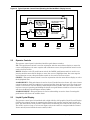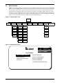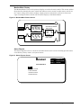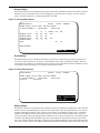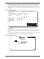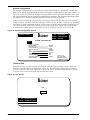
1
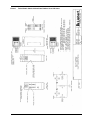
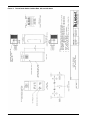
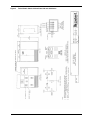
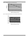
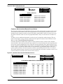
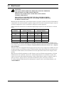
POWER PROTECTION
Static Transfer Switch
100 to 1200 Amps
Installation &
Operation
Manual
TABLE OF CONTENTS
IMPORTANT SAFETY INSTRUCTIONS . . . . . . . . . . . . . . . . . . . . . . . . . . . . . . . . . . . . . . . . . . . . . 1
1.0
INSTALLATION . . . . . . . . . . . . . . . . . . . . . . . . . . . . . . . . . . . . . . . . . . . . . . . . . . . . . . . . 2
1.1
Unpacking and Installation . . . . . . . . . . . . . . . . . . . . . . . . . . . . . . . . . . . . . . . . . . . . . . . . . 2
1.1.1
1.1.2
1.1.3
1.1.4
1.1.5
1.1.6
1.1.7
1.2
Unpacking and Preliminary Inspection . . . . . . . . . . . . . . . . . . . . . . . . . . . . . . . . . . . . . . . .
Handling Considerations . . . . . . . . . . . . . . . . . . . . . . . . . . . . . . . . . . . . . . . . . . . . . . . . . . . .
Unit Preparation . . . . . . . . . . . . . . . . . . . . . . . . . . . . . . . . . . . . . . . . . . . . . . . . . . . . . . . . . .
Location Considerations . . . . . . . . . . . . . . . . . . . . . . . . . . . . . . . . . . . . . . . . . . . . . . . . . . . .
Floor Pedestal Installation . . . . . . . . . . . . . . . . . . . . . . . . . . . . . . . . . . . . . . . . . . . . . . . . . .
Attachment of the Static Switch to the Precision Power Center. . . . . . . . . . . . . . . . . . . . .
Leveling of the Static Switch Without Floor Pedestals . . . . . . . . . . . . . . . . . . . . . . . . . . . .
2
2
6
6
8
9
9
Power and Control Wiring . . . . . . . . . . . . . . . . . . . . . . . . . . . . . . . . . . . . . . . . . . . . . . . . . 10
1.2.1
1.2.2
1.2.3
1.2.4
Input And Output Power Connections . . . . . . . . . . . . . . . . . . . . . . . . . . . . . . . . . . . . . . . .
Input Junction Box Installation (If Used) . . . . . . . . . . . . . . . . . . . . . . . . . . . . . . . . . . . . .
System Grounding . . . . . . . . . . . . . . . . . . . . . . . . . . . . . . . . . . . . . . . . . . . . . . . . . . . . . . . .
Control Wiring Connections . . . . . . . . . . . . . . . . . . . . . . . . . . . . . . . . . . . . . . . . . . . . . . . .
11
12
12
12
2.0
OPERATING INSTRUCTIONS . . . . . . . . . . . . . . . . . . . . . . . . . . . . . . . . . . . . . . . . . . . . . 14
2.1
Operator Control Panel . . . . . . . . . . . . . . . . . . . . . . . . . . . . . . . . . . . . . . . . . . . . . . . . . . . 14
2.2
Operator Controls . . . . . . . . . . . . . . . . . . . . . . . . . . . . . . . . . . . . . . . . . . . . . . . . . . . . . . . . 15
2.3
Liquid Crystal Display . . . . . . . . . . . . . . . . . . . . . . . . . . . . . . . . . . . . . . . . . . . . . . . . . . . . 15
2.4
Menu Screens . . . . . . . . . . . . . . . . . . . . . . . . . . . . . . . . . . . . . . . . . . . . . . . . . . . . . . . . . . . 16
2.5
Operating Guidelines . . . . . . . . . . . . . . . . . . . . . . . . . . . . . . . . . . . . . . . . . . . . . . . . . . . . . 26
2.5.1
2.5.2
2.5.3
2.5.4
Normal System Turn-On . . . . . . . . . . . . . . . . . . . . . . . . . . . . . . . . . . . . . . . . . . . . . . . . . . .
Manual Transfer / Preferred Source Selection . . . . . . . . . . . . . . . . . . . . . . . . . . . . . . . . . .
Maintenance Bypass . . . . . . . . . . . . . . . . . . . . . . . . . . . . . . . . . . . . . . . . . . . . . . . . . . . . . .
Normal System Shutdown . . . . . . . . . . . . . . . . . . . . . . . . . . . . . . . . . . . . . . . . . . . . . . . . . .
26
26
27
27
2.6
Alarm Messages . . . . . . . . . . . . . . . . . . . . . . . . . . . . . . . . . . . . . . . . . . . . . . . . . . . . . . . . . 28
2.7
Communication Interfaces . . . . . . . . . . . . . . . . . . . . . . . . . . . . . . . . . . . . . . . . . . . . . . . . . 30
3.0
MAINTENANCE . . . . . . . . . . . . . . . . . . . . . . . . . . . . . . . . . . . . . . . . . . . . . . . . . . . . . . 31
i
FIGURES
Figure 1
Figure 2
Figure 3
Figure 4
Figure 5
Figure 6
Figure 7
Figure 8
Figure 9
Figure 10
Figure 11
Figure 12
Figure 13
Figure 14
Figure 15
Figure 16
Figure 17
Figure 18
Figure 19
Figure 20
Figure 21
Figure 22
Figure 23
Figure 24
Figure 25
Figure 26
Figure 27
Figure 28
Figure 29
Typical Static Switch Cabinet Data, Ratings Up to 250 Amps . . . . . . . . . . . . . . . . . . . . . . . . . 3
Typical Static Switch Cabinet Data, 400 and 600 Amps . . . . . . . . . . . . . . . . . . . . . . . . . . . . . . 4
Typical Static Switch Cabinet Data, 800 and 1200 Amps . . . . . . . . . . . . . . . . . . . . . . . . . . . . . 5
Recommended Derating for High Altitude Operation . . . . . . . . . . . . . . . . . . . . . . . . . . . . . . . . 7
Maximum Ambient Temperature for Full Load Operation at Higher Altitudes . . . . . . . . . . . 7
Floor Pedestal Details. . . . . . . . . . . . . . . . . . . . . . . . . . . . . . . . . . . . . . . . . . . . . . . . . . . . . . . . . . 8
Typical Static Switch One-Line Diagram . . . . . . . . . . . . . . . . . . . . . . . . . . . . . . . . . . . . . . . . . 10
Typical One-Line Diagram for Static Switch on the Output of the Precision Power Center
Transformers . . . . . . . . . . . . . . . . . . . . . . . . . . . . . . . . . . . . . . . . . . . . . . . . . . . . . . . . . . . . . . . . 10
Typical Control Wiring Connections . . . . . . . . . . . . . . . . . . . . . . . . . . . . . . . . . . . . . . . . . . . . . 13
Typical Operator Control Panel (Showing the Monitor/Mimic Display Screen) . . . . . . . . . . . 15
Operator Menu Tree . . . . . . . . . . . . . . . . . . . . . . . . . . . . . . . . . . . . . . . . . . . . . . . . . . . . . . . . . . 16
Master Menu Screen . . . . . . . . . . . . . . . . . . . . . . . . . . . . . . . . . . . . . . . . . . . . . . . . . . . . . . . . . . 16
Monitor/Mimic Display Screen . . . . . . . . . . . . . . . . . . . . . . . . . . . . . . . . . . . . . . . . . . . . . . . . . . 17
Status Reports Screen. . . . . . . . . . . . . . . . . . . . . . . . . . . . . . . . . . . . . . . . . . . . . . . . . . . . . . . . . 17
Present Status Screen. . . . . . . . . . . . . . . . . . . . . . . . . . . . . . . . . . . . . . . . . . . . . . . . . . . . . . . . . 18
Event History Screen . . . . . . . . . . . . . . . . . . . . . . . . . . . . . . . . . . . . . . . . . . . . . . . . . . . . . . . . . 18
History Status Screen . . . . . . . . . . . . . . . . . . . . . . . . . . . . . . . . . . . . . . . . . . . . . . . . . . . . . . . . . 19
System Status Screen . . . . . . . . . . . . . . . . . . . . . . . . . . . . . . . . . . . . . . . . . . . . . . . . . . . . . . . . . 19
System Configuration Screen . . . . . . . . . . . . . . . . . . . . . . . . . . . . . . . . . . . . . . . . . . . . . . . . . . . 20
Time Screen . . . . . . . . . . . . . . . . . . . . . . . . . . . . . . . . . . . . . . . . . . . . . . . . . . . . . . . . . . . . . . . . . 20
Auto Dial Setting Screen . . . . . . . . . . . . . . . . . . . . . . . . . . . . . . . . . . . . . . . . . . . . . . . . . . . . . . 21
Setpoints Screen . . . . . . . . . . . . . . . . . . . . . . . . . . . . . . . . . . . . . . . . . . . . . . . . . . . . . . . . . . . . . 22
Source Transfer Screen. . . . . . . . . . . . . . . . . . . . . . . . . . . . . . . . . . . . . . . . . . . . . . . . . . . . . . . . 22
Start-Up Procedures Screen 1 . . . . . . . . . . . . . . . . . . . . . . . . . . . . . . . . . . . . . . . . . . . . . . . . . . 23
Start-Up Procedures Screen 2 . . . . . . . . . . . . . . . . . . . . . . . . . . . . . . . . . . . . . . . . . . . . . . . . . . 23
Bypass Procedures Screen 1 . . . . . . . . . . . . . . . . . . . . . . . . . . . . . . . . . . . . . . . . . . . . . . . . . . . . 24
Bypass Procedures Screen 2 . . . . . . . . . . . . . . . . . . . . . . . . . . . . . . . . . . . . . . . . . . . . . . . . . . . . 24
Meter Calibration Screen . . . . . . . . . . . . . . . . . . . . . . . . . . . . . . . . . . . . . . . . . . . . . . . . . . . . . . 25
Customer Alarm interface Definitions Screen . . . . . . . . . . . . . . . . . . . . . . . . . . . . . . . . . . . . . 25
TABLES
Table 1
Table 2
Table 3
ii
Alarm Messages . . . . . . . . . . . . . . . . . . . . . . . . . . . . . . . . . . . . . . . . . . . . . . . . . . . . . . . . . . . . . 29
Terminal/Modem Commands . . . . . . . . . . . . . . . . . . . . . . . . . . . . . . . . . . . . . . . . . . . . . . . . . . . 30
IMPORTANT SAFETY INSTRUCTIONS
Save these instructions
This manual contains important instructions that should be followed during the installation and
maintenance of the Static Transfer Switch.
!
WARNING
THE UNIT IS SUPPLIED BY MORE THAN ONE POWER SOURCE.
UNIT CONTAINS HAZARDOUS VOLTAGES IF ANY OF THE
INPUT SOURCES IS ON, EVEN WHEN THE UNIT IS IN BYPASS.
TO ISOLATE THE UNIT, TURN OFF AND LOCK OUT ALL INPUT
POWER SOURCES.
VERIFY THAT ALL INPUT POWER SOURCES ARE DEENERGIZED AND LOCKED OUT BEFORE MAKING
CONNECTIONS INSIDE UNIT.
LETHAL VOLTAGES EXIST INSIDE THE UNIT DURING
NORMAL OPERATION. ONLY QUALIFIED SERVICE
PERSONNEL SHOULD PERFORM MAINTENANCE ON THE
STATIC SWITCH.
NOTE
Read the entire manual before installing or operating the system. Adhere to
all operating instructions and warnings on the unit and in this manual.
The unit should not be loosened from its shipping pallet until all handling
by forklift or pallet jack is completed.
The Floor Pedestals may be reverse assembled for shipping. Before
installing the pedestals, be sure they are assembled properly.
Liebert Corporation neither recommends nor knowingly sells this product
for use with life support or other FDA-designated “critical” devices.
The Static Transfer Switch is suitable for indoor use only. Protect unit
from excessive moisture and install in an area free from flammable liquids,
gases, or corrosive substances.
The unit is designed to operate from solidly grounded AC power sources
only. Provide input overcurrent protection in accordance with the unit
ratings. Wire and ground the unit according to national and local
electrical safety codes. All wiring should be installed by a qualified
electrician.
Before unit is placed into service for the first time, after equipment
relocation, or after the unit has been de-energized for an extended period of
time, a thorough equipment inspection and supervised start-up by
qualified service personnel are strongly recommended.
!
CAUTION
This unit complies with the limits for a Class A digital device,
pursuant to Part 15 Subpart J of the FCC rules and EN550022.
These limits provide reasonable protection against harmful
interference in a commercial environment. This unit generates,
uses and radiates radio frequency energy and, if not installed and
used in accordance with this instruction manual, may cause
harmful interference to radio communications. Operation of this
unit in a residential area may cause harmful interference that the
user must correct at his own expense.
1
1.0
INSTALLATION
1.1
Unpacking and Installation
NOTE
Read the entire manual before installing and operating the system. Upon
receipt of the Precision Power Center Static Switch, the installer should
perform the following steps to assure a high-quality installation.
1.1.1
Unpacking and Preliminary Inspection
A high-quality installation begins on the receiving dock.
1. Upon receipt and before unpacking, inspect the shipping crate for damage or mishandling.
Check the Shock-Watch™ indicator. If indicator is red, note on shipper’s receipt and check for
concealed damage. If any damage as a result of shipping is observed, file a damage claim with
the shipper within 24 hours and contact your local Liebert representative or Liebert Global
Services at 1-800-543-2378 to inform them of the damage claim and the condition of the
equipment.
2. If unit is to be stored before installation, it is recommended to store the unit in a dry
environment with temperatures in the range of 0°C to 40°C. Use original packing materials or
other suitable means to keep the unit clean. When opening the shipping crate, use care not to
puncture the container with sharp objects.
NOTE
The unit should not be loosened from the shipping pallet until all handling
by forklift or pallet jack is completed.
1.1.2
Handling Considerations
The Static Switch is bolted to a wooden shipping pallet to allow handling by forklift equipment.
Easily Moved—The unit is furnished with integral castors that allow the unit to be rolled into
place after it has been unbolted and removed from the shipping pallet.
Check the unit size and weight—Refer to the cabinet drawings furnished with the unit for size
and weight. Typical cabinet dimensions are shown in Figure 1 through Figure 3. Typical unit
weights are:
100-250 amp
500 lb (225 kg)
400-600 amp
750 lb (340 kg)
800-1200 amp
1700 lb (770 kg).
Plan the route—The route that the unit will follow to its installed location should be planned to
ensure that all passages are large enough to accommodate the unit and support the weight. For
example, are the doorways, elevators, ramps, etc., adequate? Are there any nonnegotiable corners
of offsets in hallways?
Move with care—In order to prevent panel damage, it is recommended that the exterior panels
be removed before the unit is moved and replaced once handling is complete. When replacing the
exterior panels, remember to reconnect all panel ground wires.
2
Installation
Figure 1
Typical Static Switch Cabinet Data, Ratings Up to 250 Amps
Installation
3
Figure 2
4
Typical Static Switch Cabinet Data, 400 and 600 Amps
Installation
Figure 3
Typical Static Switch Cabinet Data, 800 and 1200 Amps
Installation
5
1.1.3
Unit Preparation
To remove unit from the shipping pallet, set the pallet in a level area where there is enough room
to maneuver and remove the unit.
Remove the rear and side panels (if furnished) to provide access to the unit frame and to prevent
damage to the exterior panels during handling. Be sure to carefully disconnect the panel ground
wires by pulling the quick-disconnect terminals at the unit frame before lifting off the panels.
Remove the bolts holding the unit to the shipping pallet (located in the base of the unit). Remove
the shipping blocks from under the frame of the unit.
If unit is provided with an unloading ramp, locate the ramp against the pallet at the front or rear
of the unit. Secure ramp to the pallet such as by nailing the overlapping edge of the ramp to the
pallet. Carefully roll the unit off the pallet onto the floor.
If unit is not provided with an unloading ramp, use unit lifting equipment to raise the unit off the
pallet and onto the floor.
Roll the unit to its intended location. Before maneuvering the unit to the intended location, see
1.1.4 - Location Considerations.
1.1.4
Location Considerations
The Static Switch is intended to be bolted to the associated Precision Power Center. The unit may
also be used without a Precision Power Center, but then it must be equipped with the optional
side panels.
If unit is used with a Precision Power Center, the recommended location is bolted to the Precision
Power Center to minimize the interconnecting cable runs.
Operating Environment— The unit is designed to be installed indoors where the ambient air
temperature is in the range of 0°C and 40°C with a relative humidity of 0% to 95% non-condensing.
The unit is designed with top and bottom cable terminations to allow maximum flexibility in its
installation. If bottom cable entry is used, sufficient cable bending space must be provided by a
raised floor or the optional floor pedestals.
Altitude—The standard units are designed for full load operation up to 4000 feet (1200m) above
sea level. See Figure 4 for recommended deratings for altitudes greater than 4000 feet (1200 m).
Operation at full load at higher altitude can be accommodated in ambient temperatures less than
40°C ambient. Figure 5 shows the maximum allowable ambient temperature for full load operation at altitudes above 4000 feet (1200 m).
Recommended Minimum Service Clearances are at the front and rear of the unit. Side
access is required on 80 to 600 amp units to facilitate input/output connections and to allow maintenance of input/output connections. The minimum service clearance required by the National
Electrical Code (NEC) Article 110-16 is 30 in. (762 mm) for units with voltages up to 150 volts to
ground and 42 in. (1067 mm) for units with voltages over 150 volts to ground. Clearance of at least
18 in. (457 mm) is required above the unit for cooling air flow.
Heat Output—The unit produces minimal heat during normal operation.
6
Switch Size
Heat Output
BTU/Hr (kW)
100/100 amp
1,600 (0.47)
250/250 amp
2,800 (0.82)
400/400 amp
4,000 (1.17)
600/480 amp
5,600 (1.64)
800/640 amp
8,000 (2.34)
1200/960 amp
11,000 (3.22)
Installation
Figure 4
Recommended Derating for High Altitude Operation
100
Rating (%)
98
96
94
92
90
88
10000
9500
9000
8500
8000
7500
7000
6500
6000
5500
5000
4500
4000
0
86
Altitude (Feet Above Sea Level)
Maximum Ambient Temperature for Full Load Operation at Higher Altitudes
10000
9500
9000
8500
8000
7500
7000
6500
6000
5500
5000
4500
4000
40
39
38
37
36
35
34
33
32
31
30
0
Max. Ambient Temperature (C)
Figure 5
Altitude (Feet Above Sea Level)
Installation
7
1.1.5
Floor Pedestal Installation
Floor pedestals are optional equipment intended to provide bottom cable clearance without relying on a raised floor to support the unit. The pedestals are adjustable over a limited range
(approximately 3 1/2 in. [89 mm]) to allow leveling of the unit and minor adjustments of the
installed height.
If floor pedestals are used for the Precision Power Center, additional floor pedestals are required
for the Static Switch.
NOTE
The floor pedestals may be reverse assembled for shipping. Before
installing the pedestals, be sure they are assembled as shown in Figure 6.
When the pedestal is properly assembled, the washer on the top provides a
bearing surface for the unit, the welded nut provides a means to raise and
lower the height, and the jam nut provides a means to lock the height of the
pedestal.
To install the pedestals, insert the pedestal shaft into the tubing provided in the unit’s base.
Adjust the unit height by turning the welded nut/shaft assembly into or out of the pedestal base.
Lock the height by tightening the jam nut against the pedestal base.
The pedestal may be mounted to the floor by means of the four holes provided in the pedestal
base.
Figure 6
Floor Pedestal Details
3”
(76mm)
Threaded Shaft
Washer
Welded Nut
Jam Nut
Pedestal
Base
0.56” (14mm) Dia.
Mounting Holes
2.25”
(57mm)
2.25”
(57mm)
2.25”
(57mm)
8
Installation
2.25”
(57mm)
6”
(152mm)
Square
1.1.6
Attachment of the Static Switch to the Precision Power Center
The Static Switch can be bolted to either the left or right side of a Precision Power Center having
the same height and depth. For Static Switches applied on the input to the Precision Power Center (see Figure 7), left side mounting is preferred. For Static Switches applied on the output of
the transformer (see Figure 8), the Static Switch is recommended to be located in between the
two Precision Power Centers.
After determining the location of the Static Switch, if bottom cable entrance/exit is required and a
raised floor is used, provide a cutout in the raised floor for the bottom cable entrance/exit.
To attach the Static Switch to a Precision Power Center, follow the same procedures as for attaching a sidecar to the Precision Power Center. Remove the side panel, the upper panel retainers,
and the lower panel hooks from the Precision Power Center and save for use on the Static Switch.
Align the Static Switch and Precision Power Center frames and bolt the frames together using the
hardware provided (bolts, washers, nuts, and spacers), one set in each corner, utilizing matching
holes in the frames.
If the Static Switch is on the outside of the line-up, install the upper panel retainers and lower
panel hooks that were removed from the Precision Power Center.
After electrical connections are completed, install the side panels. Be sure to reconnect the panel
ground wires.
1.1.7
Leveling of the Static Switch Without Floor Pedestals
The Static Switch is furnished with casters and leveling feet. After final positioning of the unit in
installations without floor pedestals, adjust the leveling feet located in each corner of the frame
base to level and stabilize the unit.
Installation
9
Figure 7
Typical Static Switch One-Line Diagram
SOURCE 1
SOURCE 2
STS1
CB1
STS2
CB2
K2
K1
K2 K3
CB4
CB3
K1 K3
CB5
OUTPUT
Figure 8
Typical One-Line Diagram for Static Switch on the Output of the Precision Power Center
Transformers
SOURCE 1
SOURCE 2
MICB1
MICB2
ISOLATION
TRANSFORMER
CB1
STS1
ISOLATION
TRANSFORMER
STS2
K2
K1
K2 K3
225A
1.2
225A
CB4
225A
CB2
CB3
K1 K3
CB5
225A
225A
225A
Power and Control Wiring
All power and control wiring should be installed by a qualified electrician. All power and control
wiring must comply with the NEC and applicable local codes. Unless otherwise labeled, the recommended tightening torque is as shown in 3.0 - Maintenance.
10
Installation
1.2.1
Input And Output Power Connections
If the unit is furnished with input junction boxes, the input power connections are made to the
input power terminals located in the junction boxes. Input power cables, furnished with the input
junction boxes, are shipped unattached to the unit for connection between the junction boxes and
the lugs provided inside the unit.
If junction boxes are not furnished, the input power connections are made to the lugs provided
inside the unit.
Output power connections are made to the lugs provided inside the unit. See unit wiring diagrams
furnished with the unit.
!
WARNING
RISK OF ELECTRIC SHOCK
VERIFY THAT ALL INPUT POWER AND CONTROL CIRCUITS
ARE DE-ENERGIZED AND LOCKED OUT BEFORE MAKING
CONNECTIONS INSIDE UNIT.
The two input power feeds to the Static Switch should be from two independent sources to avoid a
common source failure. Further, to ensure proper operation of the Static Switch, the two input
sources must be the same nominal voltage level and phase rotation. For uninterrupted automatic
transfer, the two input sources should be synchronized within 15 degrees.
!
WARNING
RISK OF UNIT DAMAGE
THE INPUT SOURCES TO THE STATIC SWITCH MUST BE
GROUNDED-WYE SOURCES. INPUT SOURCES OTHER THAN
SOLIDLY GROUNDED-WYE SOURCES MAY CAUSE DAMAGE TO
THE SWITCH.
The Static Switch is designed for operation with 3- or 4-wire solidly grounded sources only. For 4wire operation, the common source neutral must be connected to the Static Switch. See Figure 7
for a typical one-line diagram. Refer to the unit wiring diagram.
The input and output power wire size should be based on the upstream overcurrent protection
device, observing the NEC and local codes. If the Static Switch is bolted to the Precision Power
Center, the intra-cabinet interconnecting wiring can be sized based on NEC Table 310-17.
The molded case switches contained in the Static Switch are typically non-automatic circuit
breakers that rely on the upstream and/or load overcurrent protection. Upstream overcurrent protection should be rated equal to or less than the rating of the Static Switch molded case breakers.
The Static Switch input and output power and ground lugs accommodate a wide range of wire
sizes:
Switch Size
Power and Ground Lug Wire Range
100 amp
#14 to #2/0 AWG
250 amp
#4 AWG to 350 kcmil
400 amp
(2)#4 AWG to (2) 350 kcmil
600 amp
(2)#4 AWG to (2) 350 kcmil
800 amp
(3) #2/0 AWG to (3) 500 kcmil power
(3) #4 AWG to (3) 350 kcmil ground
1200 amp
(4) #2/0 AWG to (4) 500 kcmil power
(4) #4 AWG to (4) 350 kcmil ground
Installation
11
1.2.2
Input Junction Box Installation (If Used)
The input junction box option is available to simplify input connections to the Static Switch. Two
input junction boxes and the associated flexible 10 foot long (3 meters) input cables are provided.
(This option is available only with bottom cable entrance, typically when the unit is located on a
raised floor.)
The junction boxes, if used, can be shipped with the unit or advanced shipped for installation during the rough-in stage of construction. Locate the junction boxes a maximum of 8 feet (2.4 meters)
from the planned location of the Static Switch.
Due to a lack of clearance for the cables below the unit, the cables are also shipped loose from the
unit for installation at the site. The input cables connect from the input junction boxes to the
input power lugs inside the Static Switch.
The standard configuration for the input junction boxes and cables is for 3-wire-plus-ground
feeds. If the input neutral is required, special 4-wire-plus-ground input cables and junction boxes
are required. Consult factory for details.
Junction box dimensions are as follows:
Switch Size
Length
Inches (mm)
Width
Inches (mm)
Height
Inches (mm)
100 amp
16 (406)
14 (356)
6 (152)
250 to 600 amp
30 (762)
16 (406)
6 (152)
The junction box terminal wire size range is:
1.2.3
Switch Size
Power and Ground Lug Wire Range
100 amp
#14 to #2/0 AWG
250 to 600 amp
(2) #4 AWG to (2) 500 kcmil
System Grounding
Equipment grounding—Grounding is primarily for equipment and personnel safety, although
proper grounding also enhances equipment performance.
All input and output power feeds must include an equipment grounding means as required by the
NEC and local codes.
An insulated equipment ground conductor is recommended to run with each input and output
power feed. The equipment ground conductors should be at least the minimum size conductor per
the NEC based on the upstream overcurrent protection device.
If conduit is used as a grounding means, adequate electrical continuity must be maintained at all
conduit connections. The use of isolating bushings with a metal conduit can be a safety hazard
and is not recommended.
4-Wire-Plus-Ground Systems—When 4-wire-plus-ground input feeds are utilized, the input
power sources must be properly grounded. Because the neutral is not switched by the Static
Switch, the neutrals of the two power sources will be solidly interconnected. The NEC prohibits
grounding a power source at more than one point. Connecting the neutrals of two grounded power
sources together effectively grounds each of the sources at more than one point, which allows neutral current to flow on the ground system, defeats ground fault protection, creates a safety hazard,
and violates the NEC. Where possible, the two power sources should be located in close
proximity and a single neutral-to-ground bond made (as shown in Figure 8 or as is typical
with a double-ended substation).
1.2.4
Control Wiring Connections
All external control wiring to/from the Static Switch is optional and consists of relay contacts indicating switch status, modem and remote monitoring connections. Connections are made to terminal blocks located in the monitoring compartment. See Figure 9 for typical relay contact outputs.
Refer to the wiring diagram furnished with the unit.
12
Installation
For alarm annunciation with Precision Power Centers, it is recommended that the N.O.
summary alarm contact and N.C. auto transfer enable contact be connected to two of the Precision
Power Center PMP N.O. customer alarm inputs (Precision Power Center control terminals 9 and
10, 9 and 11, 9 and 12, or 9 and 13) to alarm when the
Static Switch has an alarm condition (summary alarm) and when the Static Switch is not able to
make an automatic transfer (such as when one of the input sources is not available, the two input
sources are not synchronized, there is a switch failure, etc.). Be sure to program customer alarm
messages for these two contacts, such as “STATIC SWITCH ALARM” and “STS XFER INHIBIT.”
For modem and remote monitoring information, refer to 2.7 - Communication Interfaces.
For Customer Alarm Interface and Remote Source Selection information, refer to Customer Alarm Interface/Remote Source Select in 2.0 - Operating Instructions.
Figure 9
Typical Control Wiring Connections
Summary
Alarm
K1
1
3
5
Auto Xfr
Enabled
K2
7
9
Source 1
Available
K3
11
13
15
17
Source 2
Available
K4
19
21
23
STS on
Source 1
K6
In Sync
K5
25
27
29
31
33
35
STS on
Source 2
K7
37
39
41
Isolated Relay Output Contacts
RS-232
PORT
(Full Duplex)
TXD
RXD
GROUND
1
2
3
4
MODEM
PORT
RS-232
PORT
(Simplex)
DCD
TXC
RXD
GROUND
TXD
GROUND
SiteScan Interface
(RS422)
5
6
7
8
9
10
11
12
13
14
15
16
RS232 / Terminal
Communication Ports
1
2
Twisted Pair
#22 AWG Min.
To SiteScan
SiteScan
Communication Port
STS
Overload
K8
43
45
47
Dry Contacts
(By Others)
TB1 1 #1
2
3
#2
Alarm
4
Interface 5 #3
6
Board
7
#4
8
9
#5
10
TB2 1 #6
2
3
4
#7
5
6
#8
7
S2 Preferred
S1 Preferred
Optional
Customer
Alarm
Inputs
Remote Source Select /
Customer Alarm Inputs
Static Transfer Switch Control Connections
(Located Behind Mimic Panel)
Installation
13
2.0
OPERATING INSTRUCTIONS
NOTE
Before unit is placed into service for the first time, after equipment
relocation, or after the equipment has been de-energized for an extended
period of time, a thorough equipment inspection and supervised start-up by
qualified personnel are strongly recommended. Contact your local Liebert
representative or Liebert Global Services at 1-800-543-2378 to arrange for
equipment inspection and start-up.
After the initial equipment start-up, the following operating guidelines can be used for standard
equipment operation. These guidelines should be reviewed for any special equipment modifications, special site conditions, or company policies that may require changes to the standard equipment operation.
Description of Static Switch Operation—The Static Switch uses pairs of silicon controlled
rectifiers (SCRs) connected in paralleled opposing pairs to function as a switching contact. Three
pairs of SCRs connect the AC load to the selected “Preferred” source as long as the preferred
source is available. A second set of SCRs stands ready to transfer the AC load to the “Alternate”
source should the preferred source fail. The switching action is a very fast break-before-make
with less than a 1/4 cycle break in the AC waveform.
During static switch transfers and retransfers, the conduction state of the SCRs is carefully monitored and controlled to prevent a current path from one source to the other. This technique prevents a good source from feeding into the other faulted source.
The “Preferred” source is the source that will normally carry the load when both sources are available. The “Preferred” source is selectable by the user from the operator control panel. The unselected source is referred to as the “Alternate” source and will carry the load if the “Preferred”
source should fail or if a manual transfer is initiated.
Maintenance Bypass—Manually operated, key-interlocked maintenance bypass provisions
allow bypassing of the Static Switch to either source and isolation of the Static Switch for maintenance or repair. Refer to the Static Switch one-line diagram (Figure 7) and the maintenance
bypass operating instructions. While operating on maintenance bypass, all voltages can be
removed from the Static Switch electronics to facilitate safe repair.
All breakers of the Static Switch are plug-in types, which can allow any breaker to be replaced
without de-energizing the output bus. The Merlin Gerin breakers have an interlock in the plug-in
base, which prevents the breaker from being withdrawn in the ON position. The breaker will trip
OFF before it disconnects from the plug-in base.
2.1
Operator Control Panel
The Static Switch is furnished with a menu-driven operator control panel, which provides operator information and control of the Static Switch. A full-graphic liquid crystal display (LCD) is
used to display a mimic one-line diagram of the switch, monitored parameters, system status,
alarm information, history information, system setpoints, meter calibration, and operational procedures. Below the LCD are push-button switches for menu selection, alarm reset, and alarm
silence. The typical operator control panel is shown in Figure 10.
14
Operating Instructions
Figure 10 Typical Operator Control Panel (Showing the Monitor/Mimic Display Screen)
CB4
CB1
STS 1
A-B
B-C C-A
480V 480V 480V
150A 150A 150A
60.0 Hz
Preferred
CB2
STS 2
A-B
B-C C-A
480V 480V 480V
0A
0A
0A
60.0 Hz
Alternate
UP
2.2
DOWN
SELECT
Auto Retransfer Disabled
History Stored
OUTPUT
KVA
KW
125
101
Transfers
CB3
Load
10
Transfer Inhibit
Peak-I1 OVLD
CB5
ALARM
RESET
ALARM
SILENCE
Operator Controls
The operator control panel is furnished with five push-button switches.
UP—This push-button switch is used in conjunction with the menu-driven display to move the
cursor or highlight up. On some setpoint and calibration screens, this push-button switch is also
used to increase values.
DOWN—Similar to the UP push-button switch, the DOWN push-button switch is used in conjunction with the menu-driven display to move the cursor or highlight down. On some setpoint
and calibration screens, this push-button switch is also used to decrease values.
SELECT—This push-button switch is used in conjunction with the menu-driven display to select
the highlighted item.
ALARM RESET—This push button is used to clear all latched inactive alarms. All active alarms
remain in memory until the condition is corrected and the alarm has been reset. The alarm reset
switch is also used to clear the History Status Report memory buffer. After the alarm condition
has been corrected, pressing and holding the alarm reset push-button switch for at least 5 seconds
will clear the History Status Report memory buffer.
ALARM SILENCE—This push button is used to acknowledge an active alarm. Pressing this
push button will silence the audible alarm.
2.3
Liquid Crystal Display
The operator control panel is furnished with a high visibility, full-graphics Liquid Crystal Display
(LCD) as the primary means of communication between the operator and the static switch controls. The menu-driven LCD provides comprehensive monitoring and control of the static switch.
The LCD is active as long as at least one input to the static switch is energized and the Control
Power switch (located inside the static switch) is ON.
Operating Instructions
15
2.4
Menu Screens
Figure 11 shows the menu tree for the screens available to the operator on the LCD. The Master
Menu, shown in Figure 12, contains the primary menu selections for monitoring and controlling
the operation of the static switch. From any of the primary screens (accessed directly from the
Master Menu), pushing the Select switch once will return to the Master Menu. From any of the
secondary screens, pushing the Select switch twice will return to the Master Menu. Descriptions
of the push-button switch functions appear in highlighted text on each screen except the Monitor/
Mimic screen. The cursor position is indicated by the highlighted box.
Figure 11 Operator Menu Tree
Master
Menu
Monitor/
Mimic
Status
Reports
System
Configuration
Setpoints
Source
Transfer
Start-Up
Procedures
Bypass
Procedures
Meter
Calibration
Present
Status
System
Parameters
Retransfer
Delay
Source 1
Volts
Event
History
Date
Retransfer
Voltage
Source 1
Amps
History
Status
Time
Phase
Difference
Source 2
Volts
System
Status
Auto
Dial
Frequency
Deviation
Source 2
Amps
Enable
Backlight
Auto
Retransfer
Language
Selection
Counter
Reset
Customer
Alarm Definition
Figure 12 Master Menu Screen
UP : CURSOR UP
DOWN : CURSOR DOWN
SELECT : CHOOSE
MASTER MENU
MONITOR/MIMIC DISPLAY
SOURCE TRANSFER
STATUS REPORTS
START-UP PROCEDURES
SYSTEM CONFIGURATION
BYPASS PROCEDURES
SETPOINTS
METER CALIBRATION
CUSTOMER ALARM DEFINITIONS
16
Operating Instructions
Monitor/Mimic Display
The Monitor/Mimic screen is the primary display screen for the static switch. This screen mimics
the power flow through the static switch and indicates source status, breaker status, switch status, source voltage and current readings, output power measurements, and active alarm messages. Pressing the Select switch will return the display to the Master Menu.
Figure 13 Monitor/Mimic Display Screen
CB4
CB1
STS 1
A-B
B-C C-A
480V 480V 480V
150A 150A 150A
60.0 Hz
Preferred
CB2
STS 2
A-B
B-C C-A
480V 480V 480V
0A
0A
0A
60.0 Hz
Alternate
Auto Retransfer Disabled
History Stored
OUTPUT
KVA
KW
125
101
Transfers
CB3
Load
10
Transfer Inhibit
Peak-I1 OVLD
CB5
Status Reports
The Status Reports screen is a menu of available switch status screens including present status,
event history, history status, and system status.
Figure 14 Status Reports Screen
UP
: CURSOR UP
DOWN
: CURSOR DOWN
SELECT : CHOOSE
STATUS REPORTS
EXIT
PRESENT STATUS
EVENT HISTORY
HISTORY STATUS
SYSTEM STATUS
Operating Instructions
17
Present Status
The Present Status screen displays the present (real-time) conditions of the static switch, which is
updated every second while the screen is displayed. It includes active alarms, source voltages,
source currents, frequency, and the output kVA and kW.
Figure 15 Present Status Screen
PRESENT STATUS
ORDER - 000000
06/17/95
SITE ID - 00000
**** ACTIVE ALARMS ****
SOURCE 1 VOLTS
SOURCE 1 AMPS
SOURCE 2 VOLTS
SOURCE 2 AMPS
14:06:26
FRAME 35
SITE TAG - 0000000
Transfer Inhibit
A
B
C
480
150
480
0
480
150
480
0
480
150
480
0
Peak-I1 OVLD
HERTZ
KVA
KW
125
101
60.0
60.0
LOAD
END OF REPORT
SELECT : EXIT
Event History
The Event History screen displays the history of the static switch active alarms in sequence of
occurrence. The sequence of occurrence is identified by date, time, and frame number. The last
128 alarms are stored in a nonvolatile memory and can be viewed from the Event History screen
by using the Up and Down keys to sequence through the frames.
Figure 16 Event History Screen
EVENT HISTORY
ORDER - 000000
06/15/95
SITE ID - 00000
10:34:27
FRAME 41
SITE TAG - 0000000
**** ACTIVE ALARMS ****
Transfer Inhibit
Source1 Fail
Source1 UV
Peak-I1 OVLD
UP : NEXT FRAME
DOWN : PREVIOUS FRAME
SELECT : EXIT
History Status
The History Status screen displays 64 sequential frames in 4-millisecond intervals of the Present
Status screens surrounding the occurrence of a major alarm. The Up and Down keys are used to
sequence through the frames. The sequence of occurrence is identified by date, time, and frame
number. The History Status frames are stored in a nonvolatile memory buffer that is continuously overwritten until a designated fault condition occurs. Upon occurrence of a designated fault
condition, the History Status buffer stores the next 23 frames, then freezes until reset. At that
time, the “History Stored” message is displayed on the Monitor/Mimic screen and the History Status screens can be viewed. The History Status buffer then contains 40 frames before the fault, the
18
Operating Instructions
frame when the fault occurred, and the next 23 frames. The 64 frames of History Status can be a
very useful diagnostic tool. As such, it is recommended that the History Status buffer not be reset
until the designated fault condition that caused the buffer to be latched is viewed and investigated by a qualified service technician. After the alarm condition has been corrected, the History
Status buffer can be reset (unfrozen) by pressing and holding the Alarm Reset switch for at least
5 seconds.
Figure 17 History Status Screen
HISTORY STATUS
ORDER - 000000
05/20/95
SITE ID - 00000
FRAME 41
SITE TAG - 0000000
**** ACTIVE ALARMS ****
Transfer Inhibit
Source1 Fail
Source1 UV
SOURCE 1 VOLTS
SOURCE 1 AMPS
SOURCE 2 VOLTS
SOURCE 2 AMPS
LOAD
09:17:52
A
B
C
387
1021
480
0
398
1138
480
0
392
1089
480
0
Peak-I1 OVLD
HERTZ
KVA
KW
96
65
60.0
60.0
UP : NEXT FRAME
DOWN : PREVIOUS FRAME
SELECT : EXIT
System Status
The System Status screen displays the total unit operating hours and the total number of switch
transfers, which are stored in nonvolatile memory. The total operating hours can not be reset by
the user.
The total number of switch transfers is also displayed on the Monitor/Mimic screen. The number
of switch transfers displayed can be reset by the user from the Setpoints screen.
Figure 18 System Status Screen
SELECT : EXIT
SYSTEM STATUS
EXIT
Total Operating Hours
Total Transfers
000168
0078
Operating Instructions
19
System Configuration
The System Configuration screen displays the Static Switch and site “personality” information.
Some of this information, including the system parameters, model number, and order number, is
set at the factory and should be changed only by qualified service personnel. The time, date, and
auto dial parameters may be changed by qualified user personnel. The Language Selection allows
the displays to be changed to English, French, German, Italian, or Spanish.
Certain screens contain the “Security Access” message, which indicates that access for making
changes to these screens is controlled. Changes to these screens should be made only by qualified
personnel. To make authorized changes, access to the rear of the control panel is required to activate the “Interlock” push-button switch (located on the back of the hinged control panel). The
security access authorization is reset when the screen requiring security access is exited.
Figure 19 System Configuration Screen
UP : CURSOR UP
SECURITY ACCESS
DOWN : CURSOR DOWN
SELECT : CHOOSE
EXIT
SYSTEM CONFIGURATION
System Parameters
Model Number
Order Number
Site ID Number
Site TAG Number
Date
Time
Auto Dial
Enable Backlight
Language Selection
System Options
STA250
000000
00000
0000000
03/02/98
14:51:59
YES
YES
English
Version 1.05
Copyright 1998
Liebert Corporation
All Rights Reserved
Time and Date
The system’s time and date settings are changed using the Time and Date screens, which are
selectable from the System Configuration screen. The Up and Down push buttons are used to
increase or decrease the value indicated by the arrow cursor. The Select push button is used to
move the arrow cursor to the next digit and exit the screen.
Figure 20 Time Screen
Time
13:15:03
UP : INCREASE VALUE
DOWN : DECREASE VALUE
SELECT : WALK-THRU / EXIT
20
Operating Instructions
Auto Dial Setting
The Auto Dial Setting screen (which is accessed from the System Configuration screen) controls
the settings of the optional, internal modem. To change any of the auto dial settings, use the Up
or Down push-button switches to move the cursor to the setting to be changed and push the Select
switch. Use the Up or Down push-button switches to toggle the selected values to the desired setting, then press the Select push-button switch to select the desired value. In the case of the auto
dial phone numbers, pressing the Select push-button switch accepts the highlighted number and
moves the cursor to the next digit. After all changes are made, move the cursor to the Exit selection and press the Select push-button switch to return to the System Configuration screen.
Designated major alarms activate the auto dial modem sequence if the auto dial is enabled and
the unit is equipped with the optional internal modem. Automatic dial attempts are made to the
first number at periodic intervals for the first 30 minutes. If connection is not established in that
time period, the system automatically rolls over to the second number. Auto dial attempts are
made again at periodic intervals for the next 30 minutes. The process repeats itself until connection is made. Upon connection, the system transmits a present status data, which includes all
active alarms messages. If the History Buffer is frozen, the system transmits the status data for
the event that froze the History Status buffer. After transmission, the modem will automatically
hang up and return to the auto-answer mode.
Figure 21 Auto Dial Setting Screen
UP : CURSOR UP
DOWN : CURSOR DOWN
SELECT : CHOOSE
EXIT
AUTO DIAL SETTING SCREEN
Enable Auto Dial
Modem Baud Rate
Auto Dial Number
Second Number
Modem Initialization String
YES
2400
0 000 000-0000
0 000 000-0000
xxxxxxxxxxxxxxxxxxx
Operating Instructions
21
Setpoints
The Setpoints screen is used to adjust the user-accessible switch settings. To limit access to the
settings to qualified personnel, Security Access is required to make changes to the settings. The
retranslate delay settings are the time delays in auto retranslates back to the preferred source
after the preferred source is restored. The phase difference setting is the allowable phase difference between the input sources before disabling manual or auto retranslates. The frequency deviation setting is the allowable frequency variation from nominal (60.0 or 50.0 Hz) before activating
the frequency deviation alarm. The frequency setting applies to both input sources. The auto
retransfer enable setting allows enabling or disabling the auto retransfer feature of the switch
back to the preferred source after the preferred source is restored. The transfer counter reset
resets the Monitor/Mimic screen transfer counter to zero.
Figure 22 Setpoints Screen
SECURITY ACCESS
UP
: CURSOR UP
DOWN
: CURSOR DOWN
SELECT : CHOOSE
EXIT
SETPOINTS
Retransfer Delay (Sec.)
Retransfer Voltage Diff. (%)
Phase Difference (Degrees)
Frequency Deviation (0.1 Hertz)
Auto Retransfer Enabled
Transfer Counter Reset
3
8
15
5
YES
NO
Source Transfer/Preferred Source Select
The Source Transfer screen is used to manually initiate a switch transfer to the other source by
changing the preferred source selection. Transfer instructions are included on the Source Transfer Screen, shown below.
Figure 23 Source Transfer Screen
SELECT : MASTER MENU
VOLTAGE COMPARISON
A-B B-C C-A
SOURCE1 - 480 480 480
SOURCE2 - 481 480 479
SYNCHRONIZATION
FREQUENCY
60.0 Hz
60.0 Hz
-30
0
+30
SOURCE2 LEAD =
2 Deg
ON SOURCE1
TRANSFER INSTRUCTIONS
SOURCE1 IS PREFERRED
1. Verify CB2 is closed, SOURCE2 voltages are correct,
OKAY TO TRANSFER
and sources are within synchronization window.
2. If the OK TO TRANSFER message is displayed,
simultaneously press the ALARM RESET and DOWN
buttons.
3. Verify that the transfer was successful by checking the
ON SOURCE status message.
4. If TRANSFER PROHIBIT message is displayed, check
for alarm messages on the “MONITOR/MIMIC” screen.
22
Operating Instructions
Start-Up Procedures
The Start-Up Procedures screens display the typical switch turn-on procedures after the initial
switch start-up has been completed. These guidelines should be reviewed for any special equipment modifications, load equipment considerations, special site conditions, or company policies
that may require changes to the standard equipment start-up procedures.
NOTE
Before the system is placed into service for the first time, after equipment
relocation, or after the equipment has been de-energized for an extended
periods of time, a thorough equipment inspection and supervised start-up
by qualified service personnel are strongly recommended. Contact your
local Liebert representative or Liebert Global Services (in the United
States, 1-800-LIEBERT) to arrange for equipment inspection and startup.
Figure 24 Start-Up Procedures Screen 1
DOWN : NEXT PAGE
SELECT : MASTER MENU
START-UP PROCEDURES
1.
Make certain all unit breakers are OFF. The bolts of key interlocks for CB1
and CB2 should be retracted and the bolts of key interlocks for CB4 and CB5
should be extended.
2.
Verify nominal input voltages are applied to both unit inputs (SOURCE 1 and
SOURCE 2). Verify that the LCD control panel is operating properly.
Close CB1. Verify SOURCE1 and CB1 breaker status on the “MONITOR/MIMIC”
screen.
Close CB2. Verify SOURCE2 and CB2 breaker status on the “MONITOR/MIMIC”
screen.
Verify preferred source switch box and OUTPUT box are highlighted on the
“MONITOR/MIMIC” screen. (See “SOURCE TRANSFER” screen to change preferred
source).
3.
4.
5.
Figure 25 Start-Up Procedures Screen 2
UP : FIRST PAGE
SELECT : MASTER MENU
START-UP PROCEDURES (Cont’d)
6.
Close output breaker CB3. Verify CB3 breaker status on the “MONITOR/MIMIC”
screen.
7.
Press ALARM RESET. Verify that there are no active alarms.
8.
Turn ON load equipment following manufacturer’s recommendations.
Operating Instructions
23
Bypass Procedures
The Bypass Procedures screens display the typical switch bypassing procedures. Screen 1 displays instructions to bypass the switch to the current input source. Screen 2 displays instructions
to return from bypass to normal operation.
Figure 26 Bypass Procedures Screen 1
DOWN : NEXT PAGE
SELECT : MASTER MENU
BYPASS PROCEDURES (to SOURCE 1)
1.
If bypass to SOURCE1 is not desired, select the “SOURCE TRANSFER” screen
and follow the instructions to transfer the load to the desired bypass
source.
2.
Remove interlock key from CB5 and place in CB4 interlock.
3.
Open the alternate source input breaker CB2. Rotate and remove the interlock
key and insert key in the CB4 bypass breaker interlock.
4.
Rotate interlock keys in CB4 bypass breaker interlock to retract interlock.
5.
Close bypass breaker CB4. Verify breaker status on “MONITOR/MIMIC” screen.
6.
Open source input breaker CB1. Rotate interlock key and remove to lockout
breaker.
Open isolation breaker CB3 to remove power from static switch.
7.
Figure 27 Bypass Procedures Screen 2
UP : FIRST PAGE
SELECT : MASTER MENU
BYPASS PROCEDURES (Return to Normal Mode)
1.
Insert key in the CB1 breaker interlock. Rotate key to retract interlock.
2.
Close source input breaker CB1. Verify SOURCE1 and CB1 breaker status on
the “MONITOR/MIMIC” screen.
Close output breaker CB3. Verify CB3 breaker status and switch STS 1 and
OUTPUT boxes are highlighted on the “MONITOR/MIMIC” screen.
Open bypass breaker CB4. Rotate keys in CB4 interlock to extend interlock.
3.
4.
5.
Remove proper key from CB4 interlock and insert in CB2 breaker interlock.
Rotate key to retract CB2 breaker interlock.
6.
Close source input breaker CB2. Verify SOURCE 2 and CB2 breaker status on
the “MONITOR/MIMIC” screen.
Meter Calibration
The Meter Calibration screen is used to calibrate the displayed parameters. The voltages and currents for each phase of each source are adjustable individually. The kVA and kW measurements
are calculated based on the voltages and currents. To limit access to authorized personnel, Security Access is required to make changes to the calibration screen. The meter calibrations do not
affect the switch transfer setpoints, which are independently adjustable by internal controls
accessible only to qualified service personnel.
24
Operating Instructions
Figure 28 Meter Calibration Screen
SECURITY ACCESS
UP : CURSOR UP
DOWN : CURSOR DOWN
SELECT : CHOOSE
METER CALIBRATION
EXIT
SOURCE 1 VOLTS PHASE A-B
SOURCE 1 VOLTS PHASE B-C
SOURCE 1 VOLTS PHASE C-A
SOURCE 1 AMPS PHASE A
SOURCE 1 AMPS PHASE B
SOURCE 1 AMPS PHASE C
SOURCE 2 VOLTS PHASE A-B
SOURCE 2 VOLTS PHASE B-C
SOURCE 2 VOLTS PHASE C-A
SOURCE 2 AMPS PHASE A
SOURCE 2 AMPS PHASE B
SOURCE 2 AMPS PHASE C
Customer Alarm Interface/Remote Source Select
The Customer Alarm Interface Definitions Screen is used to program the customer alarm names
and actions. Each customer alarm can be programmed to latch (requiring manual reset), to be
included in the summary alarms, to freeze the history status buffer, and/or to activate the autodial. Each customer alarm can also be programmed with a delay on activation of 0 to 999.9 seconds.
To limit access to authorized personnel, security access is required to make changes. The customer alarm inputs are dry contacts connected to the optional customer alarm interface board.
Refer to 1.2.4 - Control Wiring Connections.
Customer Alarms #1 and #2 can be used for remote preferred source selection. The customer
alarm interface and remote preferred source options are activated using the system options selection on the system configuration screen. With the remote preferred source option activated, closing the customer Alarm #1 Input selects Source 2 as preferred. Closing customer Alarm #2 Input
selects source 1 as preferred. With neither or both Alarm #1 and Alarm #2 inputs closed, the
remote preferred source selection is ignored, and the current STS preferred source is retained.
The remote preferred source selection is also ignored while the unit source transfer screen is activated to allow local override of the remote source selection.
Figure 29 Customer Alarm interface Definitions Screen
SECURITY ACCESS
UP : CURSOR UP
DOWN : CURSOR DOWN
SELECT : CHOOSE
CUSTOMER ALARM INTERFACE DEFINITIONS
EXIT
Alarm Name
ALARM #1 Source 2 Preferred
ALARM #2 Source 1 Preferred
ALARM #3 Customer Alarm
ALARM #4 Customer Alarm
ALARM #5 Customer Alarm
ALARM #6 Customer Alarm
ALARM #7 Customer Alarm
ALARM #8 Customer Alarm
Latching
YES
YES
NO
NO
NO
NO
NO
NO
Summary Freeze
YES
NO
YES
NO
NO
NO
NO
NO
NO
NO
NO
NO
NO
NO
NO
NO
Dial
NO
NO
NO
NO
NO
NO
NO
NO
Delay
0
0
0
0
0
0
0
0
Operating Instructions
25
2.5
Operating Guidelines
After the initial equipment start-up, the following operating guidelines can be used for standard
equipment operation. These guidelines should be reviewed for any special equipment modifications, special site conditions, or company policies that may require changes to the standard equipment operation.
2.5.1
Normal System Turn-On
Make certain all Static Switch Breakers (CB1, CB2, CB3, CB4, and CB5) are in the OFF position
and the key interlocks for CB1 and CB2 have their bolts retracted and keys captive. The key interlocks for CB4 and CB5 should have their bolts extended, thus preventing CB4 or CB5 from being
turned ON. Building power should be applied to both static switch inputs. The LCD control panel
should be active and operate properly when at least one of the inputs is energized. Verify nominal
input voltages are applied to both inputs (Source 1 and Source 2). The input voltages, selected preferred source, breaker and switch status, and alarms are indicated on the Monitor/Mimic screen.
Close CB1. Verify that Source 1 voltages are nominal and CB1 breaker status is correctly indicated on the Monitor/Mimic screen.
Close CB2. Verify that Source 2 voltages are nominal and CB2 breaker status is correctly indicated on the Monitor/Mimic screen.
Verify that the preferred source static switch box is highlighted on the Monitor/Mimic screen,
indicating which static switch (STS1 or STS2) is On.
Close Output Breaker CB3. Verify CB3, the Output box, and the Load box are highlighted, indicating that CB3 is closed and the Output and Load are energized.
Press the Alarm Reset push-button switch to reset previous alarms. Verify on the Monitor/Mimic
screen that there are no active alarms. If any active alarms are displayed, refer to 2.6 - Alarm
Messages for a description of the alarms and possible causes. All active alarm conditions should
be corrected before proceeding.
Turn on the load equipment following the load equipment manufacturer’s recommendations. In
some applications, the static switch supplies a Precision Power Center, in which case, the normal
turn-on sequence for the Precision Power Center should be followed.
It is recommended that the LCD be left with the Monitor/Mimic screen displayed to readily see
the status of the switch and any active alarms.
2.5.2
Manual Transfer / Preferred Source Selection
From Master Menu screen on the operator control panel, select the Source Transfer screen. The
source voltages, frequencies, and synchronization values are displayed on the Source Transfer
screen, along with the transfer instructions.
Verify that the input breakers CB1 and CB2 are closed and that Source 1 and Source 2 input voltages are correct and within the synchronization window.
The Source Transfer screen displays the present input source (e.g., On Source 1), which source is
preferred (e.g., Source 1 Is Preferred), and if manual transfer is permitted or prohibited. If the
Okay To Transfer message is displayed and it is desired to transfer to the alternate source, simultaneously press the Alarm Reset and either Up or Down switches. Use the Down switch when
transfer to Source 2 is desired and the Up switch when transfer to Source 1 is desired.
When conditions are correct, the switch will transfer to the alternate source by selecting the alternate source as the preferred source. Verify that the alternate source is designated as the preferred
source and that the input source changes to the desired source (as indicated by the On Source 1 or
On Source 2 message.
If the Transfer Prohibit message is displayed, check for alarm messages on the Present Status
screen. Correct alarm conditions before attempting a source transfer.
NOTE
When the remote source selection option (Remote Control) is activated, the
change of state of customer alarm inputs #1 and #2 (Remote Preferred
Source Selection) will override the manual transfer selection when the
source transfer screen is exited.
26
Operating Instructions
2.5.3
Maintenance Bypass
The static switch is equipped with bypass breakers CB4 and CB5 to allow manual bypass of the
switch electronics to either input source in case of switch failure or for maintenance of the switch.
Through proper operation, the static switch can be bypassed without de-energizing the load using
a make-before-break switching sequence. However, the unit can be bypassed using a make-beforebreak switching sequence only to the same source that the switch is switched to, as indicated by
the highlighted STS box on the Monitor/Mimic screen or the On Source message of the Source
Transfer screen. If the switch is not connected to the source to which maintenance bypass is
desired, follow the manual transfer/preferred source select instructions to transfer the static
switch to the desired input source. In case of source or switch failure, the unit should be bypassed
only to the current input source. For convenience, bypass instructions are displayed on the
Bypass Procedures screens.
To bypass the unit to the same source that the switch is connected to, make sure that the
bypass breaker interlock key (from CB4 or CB5) is in the key interlock of the desired bypass
breaker (CB4 or CB5).
Open (turn Off) the other source static switch input breaker (CB1 or CB2) and rotate the interlock
key to extend the bolt of the key interlock thus preventing that input breaker (CB1 or CB2) from
being closed. Remove the key from the input breaker’s interlock and insert it in the key interlock
of the desired bypass breaker (CB4 or CB5). The key from CB1 only fits into the interlock of CB5
and the key from CB2 only fits into the interlock of CB4. Rotate the keys in the bypass breaker’s
interlock to retract the bolt of the bypass breaker’s interlock. The bypass breaker key interlocks
require two keys, one from the opposite source’s input breaker (CB1 or CB2) and the bypass
breaker key. There is only one bypass breaker key, which allows only one bypass breaker to be
closed at a time. Close (turn On) the bypass breaker. Verify the breaker status on the Monitor/
Mimic screen.
To isolate the static switch, open the static switch input breaker (CB1 or CB2), rotate the interlock key of the input breaker to extend the bolt, and open the output/isolation breaker CB3. To
return to normal operation from maintenance bypass, insert the key in the interlock of the
static switch input breaker (CB1 or CB2) from the same source as the closed bypass breaker.
Rotate the key to retract the interlock bolt.
Close the input breaker from the same source as the closed bypass breaker. Verify the input voltages and the breaker status on the Monitor/ Mimic screen. Close the output/isolation breaker
CB3. Verify the CB3 breaker status and that the STS and Output boxes are highlighted on the
Monitor/Mimic screen.
If the STS box, Output box, and CB3 are not highlighted, do not proceed. If the STS box,
Output Box, and CB3 are highlighted, open the bypass breaker (CB4 or CB5). Rotate the bypass
breaker interlock keys to extend the interlock bolt.
Remove the input breaker interlock key from the bypass breaker interlock and insert it in the
other source input breaker (CB1 or CB2) interlock. Rotate the key to retract the interlock bolt
from the other source input breaker.
Close the other source input breaker. Verify the other source input voltages and breaker status on
the Monitor/Mimic screen. Press the Alarm Reset to reset previous alarms. Verify that there are
no active alarms. If any active alarms are displayed, refer to 2.6 - Alarm Messages for a description of the alarms and possible causes. All active alarm conditions should be investigated and corrected.
2.5.4
Normal System Shutdown
When the static switch is operating on static switch (not maintenance bypass), turn off the load
equipment per manufacturer’s recommendations. Open CB3 to turn Off the static switch output.
Open the input breakers CB1 and CB2. To completely de-energize the unit, turn OFF building
power to both inputs to the static switch.
When the static switch is operating on bypass, turn off the load equipment per manufacturer’s
recommendations. Open the bypass breaker (CB4 or CB5) to turn Off the static switch output. To
completely de-energize the unit, turn OFF building power to both inputs to the static switch.
Operating Instructions
27
2.6
Alarm Messages
The static switch monitoring system detects and annunciates a comprehensive set of alarm conditions. Alarm messages are displayed on the Monitor/Mimic screen below the Output box. Alarm
messages remain active until the alarm condition has been corrected and the Alarm Reset switch
has been pushed. All active alarms are displayed on the Present Status screen. A record of the
last 128 alarms is stored in nonvolatile memory and can be viewed from the Event History
screens.
Upon occurrence of designated major alarms, the History Status buffer is frozen capturing the
Present Status screens before and after the alarm condition. When the History Status buffer is
frozen, the History Stored message is displayed above the Output box on the Monitor/Mimic
screen. When the History Stored message is displayed, qualified service personnel should view
the contents of the History Status buffer, investigate the cause of the alarm as soon as practical,
and reset the buffer to allow it to capture future alarm events. The History Status buffer is reset
by pressing and holding the Alarm Reset switch for five (5) seconds.
The Peak I1 OVLD and Peak I2 OVLD alarms inhibit automatic transfer due to an overload or
load fault. These alarms can be set for auto or manual transfer inhibit reset. In the auto reset
mode, transfer inhibit is reset as soon as the load current returns to normal. In the manual reset
mode, the Security Access Interlock must be activated to reset the transfer inhibit. In either
mode, the alarm message is latched and must be reset after the alarm condition has been cleared.
The cause of Peak I1 OVLD or Peak I2 OVLD needs to be investigated and resolved (such as by
reducing the overload condition or clearing the output fault) before returning the switch to normal
operation.
A shorted or open SCR alarm latches and automatically trips open a source input breaker (CB1 or
CB2) to prevent transfers in the event of an SCR failure. The SCR failure must be investigated
and repaired before returning the switch to normal operation. Both source input breakers must be
opened (such as when the unit is placed in maintenance bypass for servicing) before a shorted or
open SCR alarm can be reset.
When the system is furnished with an optional modem and a telephone line is connected to the
modem, the system can be programmed to automatically dial out upon occurrence of any of certain designated alarms. The auto-dial settings are accessed from the System Configuration
screen. For more information on the auto-dial feature, see the 2.7 - Communication Interfaces.
Table 1 lists available alarm messages, a description of the alarm, and any special functions activated with the alarm. The special functions are indicated as follows:
F—The indicated alarm Freezes the History Status buffer.
L—The indicated alarm Latches. A latched alarm remains displayed until the alarm condition has been corrected and the Alarm Reset switch has been pushed.
D—The indicated alarm initiates the Auto-Dial sequence through the optional modem.
A—The indicated alarm activates the Audible alarm
28
Operating Instructions
.
Table 1
Alarm Messages
Alarm Message
Source1 Fail
Description/Cause
Action
Input Source 1 voltages are above or below acceptable thresholds.
F, L, D, A
Source2 Fail
Input Source 2 voltages are above or below acceptable thresholds.
F, L, D, A
OF/UF
Source frequencies are above or below user-adjustable thresholds.
A
Shorted SCR1
One or more of the SCRs in STS1 have failed shorted.
F, L, D, A
Shorted SCR2
One or more of the SCRs in STS2 have failed shorted.
F, L, D, A
Open SCR1
One or more of the SCRs or fuses in STS1 have failed open.
F, L, D, A
Open SCR2
One or more of the SCRs or fuses in STS2 have failed opened.
F, L, D, A
Overload
The RMS load current has exceeded rated switch current for >5
seconds.
F, L, D, A
Peak I1 OVLD
The peak current through STS1 has exceeded the overload
threshold that inhibits source transfer.
F, L, D, A
Peak I2 OVLD
The peak current through STS2 has exceeded the overload
threshold that inhibits source transfer.
F, L, D, A
Transfer Inhibit
Uninterrupted transfer is inhibited due to input source failure,
sources out of sync, switch failure, or unit in bypass.
A
Out of Sync
The input sources are not synchronized within the user-adjustable
phase difference (synchronization window).
A
Source1 CB1 Open
Input breaker CB1 is not closed.
A
Source2 CB2 Open
Input breaker CB2 is not closed.
A
Output CB3 Open
Output breaker CB3 is not closed.
A
Bypass CB4 Closed
Bypass breaker CB4 is closed.
A
Bypass CB5 Closed
Bypass breaker CB5 is closed.
A
Auto Rexfer Failed
The switch has failed to transfer back to the preferred source after
the preferred source has been restored.
A
Power Supply Fault
One or more of the redundant control power supplies has failed.
D, A
Control Fuse Open
One or more of the control power fuses has opened.
F, L, D, A
Logic Failure
The system has detected a control logic failure.
D, A
Equip. Over Temp
The system heat sink temperature has exceeded the design limits.
A
Fan Failure
One or more of the redundant cooling fans has failed.
D, A
Auto Retransfer Primed
The automatic transfer sequence back to the preferred source after
source failure has been initiated.
(status
message)
Auto Retransfer Disabled
The feature of automatic transfer back to the preferred source after
source failure has been disabled (turned Off).
(status
message)
History Stored
The History Status buffer has been frozen by the occurrence of one
of the designated alarms. (Press and hold Alarm Reset switch for 5
seconds to clear History Status buffer).
(status
message)
Operating Instructions
29
2.7
Communication Interfaces
The static switch monitoring system includes two RS-232 communication ports, an optional
modem, an optional RS422 SiteScan Communications Port, and switch status contacts for remote
monitoring of the static switch. One of the RS-232 ports is intended for the connection to a local
terminal. The other RS-232 port is for connection to the optional modem. Connections to the communication ports are made by wiring to terminal boards located in the monitoring system compartment located behind the operator control panel. Connection points are shown on the control
wiring interconnection drawing. Typical connections are shown in Figure 9. Contact Liebert Global Services for assistance when attaching an external device to the static switch.
Data link requirements are Full Duplex Asynchronous RS-232 format. The terminal may be configured as DTE or DCE, with a Baud rate of 2400. The baud rates are 1200 or 2400 with 8 Data
Bits, 1 Stop Bit, No Parity, and Handshaking is not required.
Local Terminal Port—This communication port can be used to send switch status and history
information to a local terminal in an RS-232 format. The Present Status screen is sent to this port
whenever a new alarm occurs. Commands for requesting other information and for changing the
date and time are shown in Table 2.
Modem Port—This communication port automatically dials the programmed phone number
when a designated alarm occurs. Automatic dial attempts are made to the first phone number at
periodic intervals for 30 minutes. After that time, auto dial attempts are made to the second
phone number at periodic intervals for the next 30 minutes. The process is repeated until successful connection is made. Upon successful connection, the system transmits the Present Status
screen information, then hangs up. System status and history information can be requested and
date and time can be changed through the modem. The modem commands are shown in Table 2.
Table 2
Terminal/Modem Commands
Key(s)
30
Function
A, return
Displays the Present Status screen information.
^B, return
Displays the Event History screens starting with the most recent frame.
C, return
Displays the History Status screens starting with the most recent frame.
F (no return)
A toggle switch command to stop and start data scrolling.
G, return
Resets (unfreezes) the History Status buffer. (Do not reset the History Status buffer until
qualified personnel have reviewed its contents).
Q (no return)
Interrupts (quits) the data output.
d mm/dd/yy, return
Sets the date (month/day/year) of the monitoring system clock.
t hh:mm:ss, return
Sets the time (hour:minute:second) of the monitoring system clock.
H, return
Prompts the system to hang up the modem.
backspace
Moves terminal cursor left to cancel previous entry.
Operating Instructions
3.0
MAINTENANCE
!
WARNING
ONLY QUALIFIED SERVICE PERSONNEL SHOULD PERFORM
MAINTENANCE ON THE STATIC SWITCH.
LETHAL VOLTAGES EXIST INSIDE THE UNIT DURING
NORMAL OPERATION.
THE UNIT IS SUPPLIED BY MULTIPLE AC POWER SOURCES.
DISCONNECT AND LOCK-OUT ALL POWER SOURCES BEFORE
WORKING INSIDE UNIT.
Minimal periodic maintenance of the Static Switch is required. As with all electrical distribution
components, the system should be regularly inspected for electrical connection integrity, signs of
excessive temperatures, dirt accumulation, and proper system operation.
Unless otherwise labeled, the recommended tightening torque for all nut and bolts is as shown
below.
Shaft Size
Grade 2 Standard
Electrical Connections with
Belleville Washers
In.
Lb.-In.
N-M
Lb.-In.
N-M
#10
17
3
35
4
1/4
53
6
80
9.0
5/16
107
12
180
20.4
3/8
192
22
240
27.1
1/2
428
48
480
54.3
The Static Switch includes comprehensive system alarms and fault detection to identify operational problems. To increase the degree of confidence of proper system operation, periodic transfer
tests can be easily performed. See Source Transfer/Preferred Source Select in 2.5 - Operating Guidelines.
The Static Switch is equipped with integral transient voltage surge suppressors (TVSS). In areas
of high transient or overvoltage activity, TVSS should be inspected periodically and replaced as
needed. The TVSS modules are furnished with status lights which indicate the integrity of the
module.
Even the most reliable equipment can fail. Contact your local Liebert representative or Liebert
Global Services for assistance. In the U.S., Liebert Global Services is available to assure fast
repair of your unit with minimal downtime. Liebert Global Services offers a complete range of
start-up services, repair services, preventive maintenance plans, and service contracts.
To contact Liebert Global Services for information or repair service in the United States, call
1-800-LIEBERT.
Maintenance
31
32
Maintenance
Static Transfer Switch
100 - 1200 amps
Technical Support
U.S.A.
Outside the U.S.A.
1-800-LIEBERT
+614-841-6755 or 1-800-222-5877
U.K.
+44 (0) 1628 403200
France
+33 (0) 1 43 60 01 77
Germany
Italy
Netherlands
E-mail
Web site
Worldwide FAX
tech support
+49 89 99 19 220
+39 2 98250 1
+31 (0) 475 503333
[email protected]
http://www.liebert.com
+614-222-5877 option #4
The Company Behind The Products
With more than 500,000 installations around the globe, Liebert is the world leader in computer
protection systems. Since its founding in 1965, Liebert has developed a complete range of support
and protection systems for sensitive electronics:
• Environmental systems: close-control air conditioning from 1.5 to 60 tons.
• Power conditioning and UPS with power ranges from 250 VA to more than 1000 kVA.
• Integrated systems that provide both environmental and power protection in a single, flexible
package.
• Monitoring and control — on-site or remote — from systems of any size or location
Service and support, through more than 100 service centers around the world, and a 24-hour
Customer Response Center.
While every precaution has been taken to ensure accuracy and completeness of this literature,
Liebert Corporation assumes no responsibility, and disclaims all liability for damages resulting
from use of this information or for any errors or omissions.
© 2000 Liebert Corporation. All rights reserved throughout the world. Specifications subject to
change without notice.
® Liebert and the Liebert logo are registered trademarks of Liebert Corporation. All names
referred to are trademarks or registered trademarks of their respective owners.
Printed in U.S.A.
SL-20530
Revised: October 2000