1
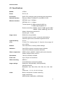
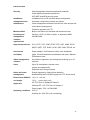
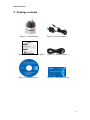
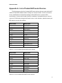
E-Guard
802.11 b/g Wireless IP Camera
With pan/tilt function
Model : IC502w
User Manual
Mundo Digital Guatemala
http://www.digimundos.com
Revision: 000109
Date: 2008/9/2
For firmware version v010711
E-Guard IC502w
Table of Contents
1.
INTRODUCTION..........................................................................................................................6
2.
HARDWARE DESCRIPTION AND QUICK INSTALLATION/USAGE ................................8
3.
4.
5.
2.1.
MAJOR HARDWARE COMPONENTS. ......................................................................................8
2.2.
QUICK INSTALLATION AND USAGE ........................................................................................9
2.3.
WIRELESS CONNECTION .....................................................................................................13
WEB CONFIGURATIONS ........................................................................................................15
3.1.
INFORMATION ......................................................................................................................16
3.2.
VIDEO DISPLAY ...................................................................................................................17
3.3.
NETWORK ............................................................................................................................19
3.4.
WIFI SECURITY ....................................................................................................................21
3.5.
ADVANCED NETWORK.........................................................................................................24
3.6.
VIDEO SETTINGS .................................................................................................................25
3.7.
3GPP/RTSP SETTINGS ......................................................................................................27
3.8.
MOTION DETECTION............................................................................................................28
3.9.
SD-CARD RECORD CONTROL..............................................................................................30
3.10.
MICRO-SD CARD RECORDED FILES DISPLAY .....................................................................31
3.11.
LED DISPLAY CONTROL ......................................................................................................32
3.12.
DATE/TIME ...........................................................................................................................33
3.13.
ADMIN ..................................................................................................................................34
3.14.
UPGRADE ............................................................................................................................35
3.15.
REBOOT...............................................................................................................................37
3.16.
SAFE MODE .........................................................................................................................38
3.17.
SET TO FACTORY DEFAULT ..................................................................................................39
FEATURES AND SPECIFICATIONS......................................................................................40
4.1.
FEATURES ...........................................................................................................................40
4.2.
SPECIFICATIONS..................................................................................................................41
PACKAGE CONTENTS............................................................................................................43
APPENDIX A. LIST OF TESTED NAT/ROUTER DEVICES ........................................................44
APPENDIX B. MAXIMUM ALLOWED VIDEO USERS.................................................................45
APPENDIX C. PERFORMANCE INFORMATION .........................................................................46
APPENDIX D. TROUBLE SHOOTING............................................................................................47
APPENDIX E. 3GPP/ISMA OPERATION........................................................................................49
2
E-Guard IC502w
APPENDIX F. THIRD PARTY AND EMBEDDED WEB PAGE INTEGRATION ........................50
3
E-Guard IC502w
List of Figures and Tables
Figure 2-1: Major components in the front panel
Figure 2-2: Major components in the back panel
Figure 2-3: IP CAM connection diagram.
Figure 2-4: Connect Ethernet cable to a switch/router.
Figure 2-5: The installation CD disk
Figure 2-6: The ID/Password card
Figure 2-7: Running window of CamView program
Figure 2-8: Pop-up play-video password window
Figure 2-9: Unplug the Ethernet cable to enable the WiFi function
Figure 3-1: Open the web configuration page from CamView software
Figure 3-2: IP CAM Web configuration login page
Figure 3-3: IP CAM Information page
Figure 3-4:Video display page
Figure 3-5: Network settings page for DHCP function
Figure 3-6: Network settings page for fixed IP address
Figure 3-7: WiFi security disabled page
Figure 3-8: WiFi security enabled page
Figure 3-9: WiFi testing page
Figure 3-10: Advanced network settings page
Figure 3-11: Video settings page
Figure 3-12: 3GPP/RTSP enabled page
Figure 3-13: Motion detection enabled page
Figure 3-14: Led Control settings page
Figure 3-15: System date/time settings page
Figure 3-16: Admin settings page
Figure 3-17: Firmware upgrade settings page
Figure 3-18: Firmware upgrade status page
Figure 3-19: System reboot settings page
Figure 3-20: System reboot under-going page
Figure 3-21: Micro-SD card recording page
Figure 3-22: Safe mode information page
Figure 3-23: Stick the reset button to set to the factory default
Figure 5-1: IC502w body
Figure 5-2: Power Adaptor
Figure 5-3: Quick installation guide
Figure 5-4: Ethernet cable
4
E-Guard IC502w
Figure 5-5: Installation CD
Figure 5-6: ID/Password Card
Table A-1: List of tested Wireless AP/router devices
Table A-2: List of tested Wired NAT/router devices
5
E-Guard IC502w
1. Introduction
The IC502w IP Camera is designed with the “user-friendly” idea deep in mind. The
user can install the IC502w easily on his/her home network and then access the IP
Camera anywhere in the world through the accompanied video management software
- CamView program without setting some complicated DNS name or changing the
router’s settings. It’s just a plug & play action.
For indoor surveillance and remote monitoring, the IC502w provides the best image
quality in its class, and excellent performance. The IC502w IP Camera also provides
the best bandwidth efficiency, it offers 640x480 resolution, 30 fps frame rate, real
MPEG4 image compression ability. The built-in microphone enables remote users to
not only view, but also listen for additional monitoring options.
With 3GPP/ISMA support, users can see the video of the IP camera on any 3G
mobile phone anywhere, anytime. With pan/tilt support, users can monitor the video in
a much larger viewing angle range.
Of course, with the built-in Web server, the IC502w IP Cameras can also be
managed from a standard web browser on a Windows computer.
The IC502w IP Camera provides both wireless IEEE 802.11 b/g and wired Ethernet
network interfaces for flexible installation. It supports the WEP and WPA (Wi-Fi
Protected Access) security modes to provide the best security for wireless networks.
The IC502w IP Camera provides motion detection function. Users can easily setup
this function and receive the notification with the snapshot images through email
and/or ftp when some motion events are detected.
The IC502w IP camera is ideal for securing small businesses, home offices and
residences over a local area network and/or the Internet.
The differences
It’s very easy to see the video of the IC502w IP Camera, you only need to key in
the ID/Password of the IP CAM any where in the world, you do not need to remember
the IP address or domain name or DDNS name or port number. And you do not need
to modify the settings(like port mapping, fixed IP, DDNS, virtual server) of the
NAT/router devices, it’s just a plug & play usage.
So, the differences are the followings:
♦ Public IP address needed ?
No
♦ Dynamic DNS needed ?
No
♦ Port mapping in router?
No
♦ Virtual server in router ?
No
6
E-Guard IC502w
♦ UPnP support in router ?
No
♦ What’s needed ?
ID and Password
7
E-Guard IC502w
2. Hardware description and quick installation/usage
The IP CAM is designed to be very easy to install and use. First, let’s see the
major components of the IP CAM products.
2.1. Major hardware components.
The major components on the front panel of the IP CAM products are the built-in
microphone, lens and LEDs :
1. Microphone – for receiving the audio/voice. Effective distance is about 5 meters.
2. Lens – the focus of the lens is fixed, you do not need to spend time to adjust the
focus, the effective focus range is from 30cm to infinity.
3. Status indication LED (red) – this LED is to indicate the Internet connection status.
When the Internet connection is connected, the LED will be constant red light. If
there is any Internet connection problem, the LED will be blinking red light.
4. Ethernet indication LED (blue) – this LED is to indicate if the Ethernet link is ok
and packet traffic is sending/receiving. When the Ethernet cable is connected, the
LED is constant blue light. When there is packet sending/receiving, the LED is
blinking blue light.
Figure 2-1: Major components in the front panel
The major components on the back panel of the IP CAM products are the bracket
screw jack, power jack, Ethernet jack and reset button:
1. Bracket screw jack – this is the position to screw in the bracket of the IP CAM.
With the bracket, you can put the IP CAM on the desk, on the wall or on the ceiling.
(Bracket not provided)
2. Power jack – this is the place to plug in the power adaptor. The power needed for
this IP CAM is 5V/1.0A, please make sure you are using the correct power
adaptor.
8
E-Guard IC502w
3. Ethernet jack – this is the place to plug in the RJ45 Ethernet cable. When the
Ethernet link is ok, the Ethernet indication LED on the front side will be blue light.
4. Reset button – this is the button to reset the IP CAM to default factory settings.
You need to use a small stick like pencil or tooth stick to press the reset button for
more than 3 seconds to enable the reset function. Usually when you forgot the
administrator account, you will probably need to do this reset action to reset to the
default factory settings. Please refer to section 3.15 for more details.
5. Wall mount – this is the place to hang the IP CAM on the ceiling or on the wall.
6. Antenna – this is the 802/11 b/g wireless antenna.
7. Digital I/O : one digital input and one digital output is provided to give users control
to alarm speaker or to signal alarm detection.
Figure 2-2: Major components in the back panel
2.2. Quick installation and usage
There are only three things that you need to do to see the video from the IP CAM.
1. Connect the IP CAM to the home/office network.
2. Install the CamView software on the notebook/PC.
3. Key in the ID/password of the IP CAM(from the IP/Password card) on the
CamView, and then you can see the video.
First, Connect the IP CAM to the home/office network
Please connect the IP CAM accessaries to the IP CAM body correctly, including
the power adapter and Ethernet cable, as shown in Figure 2-3. And connect the other
end of the Ethernet cable to the home network or office network. Usually, this Ethernet
cable is plugged into a home NAT/router device or an Ethernet switch if in the office,
as shown in Figure 2-4. Since the default settings of the IP CAM use DHCP function
and very often there is a DHCP server on most of the Home/office network, the IP
CAM should be connected to the Internet immediately. The Internet status LED is
9
E-Guard IC502w
constant red light to indicate this good connection status. If the LED is blinking, please
refer to section 3.3~3.5 to try other network settings.
Figure 2-3: IP CAM connection diagram.
Figure 2-4: Connect Ethernet cable to a switch/router.
Second, Install the CamView software on the notebook/PC
Please insert the installation CD into the CD-ROM drive in your notebook or
personal computer (must be running Microsoft Windows OS). Execute the program
CamViewInstaller-xxx.exe on the disk. The program will pop-up some windows about
the installation options, please press the “next” button to proceed with the installation.
After the installation is complete, there will be a CamView icon on the desktop of your
computer screen, please execute this icon. The CamView program will run
immediately.
10
E-Guard IC502w
Figure 2-5: The installation CD disk
Third, Use CamView program to see the video
Figure 2-5 is the running window of the CamView program. If the computer and
IP CAM is connected to the same network, the IP CAM ID will be displayed in the
“Auto Search” list. You can double click the “Auto Search” to search all the connected
IP CAMs any time. The only thing left right now for seeing the video is to double click
the IP CAM ID item in the “Auto Search” list. For example, if the IP CAM ID is
001-001-029, you can then double click the 001001029 item in the “Auto Search” list
to view the video. A window asking for password input will pop up. Please key-in the
password in your ID/Password card into this field and click “ok”. The video will then be
displayed on the window.
Figure 2-6: The ID/Password card
Notice :
1. You can modify this play-video password by entering into the web configuration
pages. Please refer to section 3.6 for more information.
2. You can also add the IP CAM into the CameraList in the CamView software to
have more convenient video display, please refer to the user manual of the
CamView software for more functions.
11
E-Guard IC502w
Seeing the video in a remote location
After the IP CAM is installed and you can see the video from the CamView
software in the local network, it’s very easy to see the video in a remote location. All
you need to do is add a camera item in the “CameraList” folder of the CamView
software, key in the IP CAM ID and Password(from the ID/Password card). And then
double click this camera item. You will then see the Camera video immediately. No
further NAT/router setting modifications are needed.
Figure 2-7: Running window of CamView program
Figure 2-8: Pop-up play-video password window
12
E-Guard IC502w
2.3. Wireless connection
The IP CAM can also be connected to the home/office network through the
802.11 b/g wireless connection. There are only three things that you need to do to
have the wireless connection:
1. Set the WiFi security settings on the web configuration page.
2. Test if the WiFi settings are correct.
3. Unplug the Ethernet cable.
First, set the WiFi security settings on the web configuration page.
Make sure there is a WiFi router or AP on your home or office network. Write
down the WiFi security parameters used in this WiFi AP/router, including the SSID ,
security mode, encryption protocols and the “key” values. The supported WiFi security
mode of the IP CAM is WEP(64 bits and 128 bits) and WPA-PSK(TKIP and AES). In
most of the home/office WiFi environment, this is quite enough.
The easiest way to set the WiFi settings on the IP CAM is through CamView
software. Right-click the searched IP CAM in the “Auto Search” list and click the “Web
Configure” to open the login window of the IP CAM. Fill in all the WiFi security
parameters you have written down. The WiFi configuration is complete now.
Please refer to section 3.4 for more detailed description if needed
.
Second, test if the WiFi settings are correct
You can now test if the above WiFi settings are correct. Click the “WiFi test” on
the “WiFi Security” settings web page. The testing result will be displayed in less than
60 seconds. If the test is failed, please check the WiFi security parameters and test
again.
Third, unplug the Ethernet cable
If the WiFi test is successful, you can then enable the WiFi connection by
unplugging the Ethernet cable from the IP CAM. The IP CAM will detect the Ethernet
cable unplugged condition and start the WiFi connection. After the WiFi is connected,
the IP CAM will connect to the Internet immediately.
Notice :
1. Please remember that the WiFi connection will use a different IP address, you will
need to do the “Auto Search” function in the CamView again to find the IP CAM
again after the WiFi is connected.
2. If you want to switch back to the wired Ethernet connection, just plug in the
Ethernet cable into the IP CAM again. Do not need to disable the WiFi function on
the web pages.
13
E-Guard IC502w
Figure 2-9: Unplug the Ethernet cable to enable the WiFi function
14
E-Guard IC502w
3. Web configurations
You can login into the web configuration page by directly key-in the IP address of
the IP CAM or right-click the searched IP CAM in the “Auto Search” list of the
CamView software and click the “Web Configure” to open the login window of the IP
CAM.
Figure 3-1: Open the web configuration page from CamView software
The default login account is “admin”, leave the Password field empty.
Figure 3-2: IP CAM Web configuration login page
15
E-Guard IC502w
3.1. Information
The first page of the web configuration of the IP CAM IC502w is the information
page. You can see the model name/firmware version, IP CAM ID, registration status,
network type and current video settings( bandwidth, resolution) in this page.
The IP CAM can be viewed remotely by the CamView software only when the IP
CAM is registered. If this IP CAM is not registered, please check the Ethernet wiring of
your network environment. The “Network type” field displays the network
connection(wired or wireless) and method(DHCP, PPPoE or static ip) the IP CAM is
running. The “Video users” field displays the number of connected video viewing
users.
Figure 3-3: IP CAM Information page
16
E-Guard IC502w
3.2. Video Display
This display page allows you to view the video display and control the pan/tilt
movement of the IP camera. For the first time use of this display on a computer, an
activeX component will be automatically downloaded into the browser. This could
take some time, depends on the internet speed. The component is downloaded
from a public domain, so that the computer must be connected to the Internet.
If you want to modify the video display screen size, please refer to section 3.6
for more details.
Figure 3-4: Video display page
Pan/tilt control:
1. Control by CamView – this is to enable/disable the pan/tilt control function by
CamView software.
2. Speed – this is to control the pan/tilt moving step distance for each pan or tilt
movement, fast means larger step movement.
3. Pan – click this button will let the IP CAM do one horizontal pan scan movement.
4. Tilt – click this button will let the IP CAM do one vertical tilt scan movement.
5. Patrol control – you can set up to 5 patrol points that will let the IP CAM to patrol
through these patrol points periodically. To set the patrol point, first move the IP
CAM to the desired view position by clicking the different arrow buttons, and then
press the “position” button of the specific patrol point. The (x,y) axis values will be
17
E-Guard IC502w
updated accordingly. You can click the (x,y) axis of the patrol point to direct the
view to this specific patrol point directly. After the patrol points are set, you can
click the “Patrol” button to start the automatic patrol. The patrol movement will
remain even after power-off and power-on, and will be stopped only after pressing
“Stop” button.
6. Stay xx secs – this is the time for each patrol point to stay before going to next
patrol point.
7. Patrol – click this button to start the patrol movement of the IP CAM. After this is
started, the IP CAM will do the patrol forever even after reboot or power off/on until
stopped.
8. Stop – this will stop the patrol movement.
18
E-Guard IC502w
3.3. Network
The Network page allows you to modify the network settings of the wired
Ethernet. The default settings use DHCP to obtain an IP address automatically. In
most of the home and office network environment, there is a DHCP server running. In
this situation, by using this default settings, the IP CAM can work immediately in most
of the time.
If the Ethernet cable is unplugged, the IP CAM will lose connection. But as soon
as the Ethernet cable is plugged in again, the IP CAM will obtain a new IP address
immediately.
Figure 3-5: Network settings page for DHCP function
If the network environment does not support DHCP function, you will need to set
the network settings of the IP CAM manually. Please fill all the fields including “IP
address”, “Subnet mask”, “Default gateway” and “DNS server” to let the network work.
All these settings must be correct for your network environment, otherwise the IP
CAM can not work.
The default setting is “Obtain an IP address automatically”.
19
E-Guard IC502w
Figure 3-6: Network settings page for fixed IP address
20
E-Guard IC502w
3.4. WiFi security
You can use the wireless to connect the IP CAM to the network. If your network
environment has a 802.11 b/g router or AP running, you can check the “Enable WiFi
function” button to use the wireless.
Figure 3-7: WiFi security disabled page
In order to use the wireless network, you need to fill the following fields:
1.
SSID – this is the ID of the wireless router or AP of your wireless network
environment, must be set correctly.
2.
Security mode – this is the security mode used in the wireless router or AP. Need
to choose one of the three modes – None, WEP and WPA-PSK.
WEP : Wireless Encryption Protocol.
WPA : WiFi Protected Access.
PSK : Pre-Shared Key.
TKIP : Temporal Key Integrity Protocol.
AES : Advanced Encryption Standard.
3.
WEP mode – when the WEP mode is chosen, you need also choose between
64-bit(5 char), 64-bit(10 hex), 128-bit(13 char) and 128-bit(26 hex) encryption
mode, and then fill the WEP key correctly.
4.
WPA-PSK mode - when the WPA-PSK mode is chosen, you need also choose
between TKIP and AES encryption mode, and then fill the WPA-PSK key
correctly.
21
E-Guard IC502w
All the fields in this page must be filled correctly with the same settings the
wireless router or AP using.
Figure 3-8: WiFi security enabled page
You can also click the “WiFi test” button to check if the IP CAM can connect to
the wireless network for these settings. You will need to unplug the Ethernet cable to
enable the wireless connection after the “WiFi test” is successful.
After the setting and “Save&Apply”, do not need to restart the IP CAM to let the
WiFi work, only need to unplug the Ethernet cable.
The default setting is “Disable WiFi Function”.
22
E-Guard IC502w
Figure 3-9: WiFi testing page
23
E-Guard IC502w
3.5. Advanced Network
In some special situation, your network environment only provides PPPoE
connection(ADSL service), there is no NAT/router available. You will then need to set
the PPPoE settings in the “Advanced Network” page. Only the PPPoE username and
password are needed to let PPPoE work. After the “Save&Apply” button is pressed,
the PPPoE function will work immediately. You can check the “Registration status” in
the “Information” page to see if the IP CAM is registered using the PPPoE connection.
Please be noticed that the DHCP or static IP settings in the “Network” page can
work together with the PPPoE connection. Only that the PPPoE has higher priority, so,
if the PPPoE is working, the IP CAM will use PPPoE to connect to the Internet.
The default setting is “Disable PPPoE”.
Figure 3-10: Advanced network settings page
24
E-Guard IC502w
3.6. Video Settings
The IP CAM is designed to provide high quality video for viewing from CamView
software. In this page, you cam modify some settings related to the video viewing:
1. Password(play video) – this is the password needed for viewing the video from the
CamView software. Together with the IP CAM ID, you can view the video of this IP
CAM anywhere in the world through the Internet.
2. Internet speed – this is the Internet bandwidth of your network environment.
Higher value will generate higher video quality. But if your internet connection can
not provide more bandwidth than the specified value, the video quality could
degrade. So, please key in a value that is lower than your internet bandwidth.
3. Select resolution & frame rate automatically – you can let the system select the
suitable video resolution and frame rate automatically for you. The selection is
based on the “Internet speed” value. This is the recommended default setting.
4. Resolution – there are three choices : 160x120, 320x240 and 640x480. If you
decide to choose the value manually, you can choose one of the three values. But,
please be noticed that if the Internet speed is slow(low value), high
resolution(640x480) or frame rate could cause very bad video quality.
5. Frame rate – the video frame display rate. Higher value means faster movement
and continuity in the video display.
6. Favor/Preference – choose between “Video motion” and “Image quality”. When
the real bandwidth is not enough for the selected “Internet speed”, the system will
need to degrade the video motion or image quality. This selection will decide if the
user want to maintain the “video motion” or “image quality” when the internet
speed is not good enough.
7. Brightness – the brightness of the video, lower value means darker display.
8. Low light ability – The low light ability could be enabled or disabled. When the low
light ability is enabled, the system could see better video clearance under low light
situation, but the moving object will not be very clear under this low light
environment.
9. Video color – choose between “colored” and “black&white”.
10. Video reversal – can do “vertical” and/or “horizontal” video reversal display, this is
needed if the ip camera is hung on the ceiling or wall.
11. Outdoor/Indoor video – for better video display quality, modify this setting when
taking indoor or outdoor video. The default setting is “Outdoor video”, in most
cases, this is also ok for indoor usage. Under some special cases, there could be
some strip lines on the video display when the IP camera is taking indoor video. In
this situation, change the setting to “Indoor video” will solve the problem. Please
also be noticed that in “Indoor video” setting, the video display of outdoor view is
25
E-Guard IC502w
very vague. For indoor usage, if there is strong sun light into the room, please
select the “Indoor+sun light” choice.
12. Enable/disable audio microphone – you can enable or disable the audio
microphone on the IP CAM. If disable, there will be no voice on the CamView
video viewing.
13. Enable/disable time display on video – if enabled, the date/time of the system will
be displayed on the left-upper corner of the video.
When this modification is “Save&Apply”ed, it works immediately, but all the
connected video viewing users will be disconnected.
Figure 3-11: Video settings page
26
E-Guard IC502w
3.7. 3GPP/RTSP settings
The IP CAM is able to be viewed from a 3G mobile phone, for detailed settings
on the 3G mobile phone, please refer to Appendix E.
Users can disable the 3G mobile access ability in this page. After the
3GPP/RTSP feature is disabled, no 3G mobile phone is allowed to access the video
of the IP camera. When this is disabled, the rtsp stream with MPEG2 audio is still
working, please refer to Appendix F for more details about rtsp stream with MPEG2
audio.
The “Access URL” line is the url address for 3G mobile phone to input for seeing
the video of the IP camera. Different 3G mobile may need to input this url in different
way, detailed information could be found in the user manual of different 3G mobiles.
Please be noticed that usually public IP address is needed for the IP camera, so that
the 3G mobile could access the IP camera’s video.
The default setting is “Enable 3GPP/RTSP”.
Figure 3-12: 3GPP/RTSP enabled page
27
E-Guard IC502w
3.8. Motion Detection
The IP CAM provides the motion detection function, you can enable the motion
detection ability in this page, the IP CAM will then send out an email with a jpeg
picture attached in the email and/or send out the jpeg picture file to a ftp server. The
related settings are explained below:
1. Detection sensitivity – there are three possible choices in this field.
“High” means high sensitivity, i.e., the detection is triggered by a very small
movement in the video image. If “High” is selected and the size of the moving
object is larger than about 1% of the whole video area, it is detected. Please be
noticed that the real size of the object could be large or small, anyway, the
detection is only based on the relative size of the object. Probably a small pencil
moving near the IP CAM could be detected, but a moving car far away from the IP
CAM could not be detected.
“Low” means low sensitivity, i.e., the detection is triggered by a very large
movement. If the size of the moving object is larger than about 10% of the whole
video area, it is detected. “Median” means 3% to trigger the detection.
2. Send email message – if this item is enabled, the IP CAM will send out an email
message with the jpeg picture attached to the specified email account.
3. Email recipient – this is the email address to receive the detection notice message.
An email message with the jpeg picture file named by the date/time of the
triggered moment will reach this address.
4. SMTP server – this is the SMTP server that will help to transfer the email message.
This server is irrelevant to the “Email recipient” address.
5. SMTP username/password – this the account to use the SMTP server to transfer
the email message. The SMTP server and username/password account are only
for transfer the email message to the “Email recipient”, the “Email recipient” could
be on another email server or any reachable email address.
6. SMTP server test – after the settings are filled, you could press “SMTP server test”
to check if all the settings are correct.
7. Send FTP message – if this item is enabled, the IP CAM will send out a jpeg
picture file to the specified ftp account.
8. FTP server – this is the FTP server address to receive the jpeg file.
9. FTP username/password – this is the username/password to login into the FTP
server, so, this triggered jpeg file will be allowed to reach this FTP server.
10. Remote folder – the jpeg file will be put under this folder of the FTP server.
When this modification is “Save&Apply”ed, it works immediately, but all the
connected video viewing users will be disconnected.
28
E-Guard IC502w
The default setting is “Disable Motion Detection”.
Figure 3-13: Motion detection enabled page
29
E-Guard IC502w
3.9. SD-card record control
The IP camera has a micro-SD card slot that users could insert micro-SD card
into the IP camera for video recording usage. The maximum size supported for the
micro-SD card is 2G bytes. In the “Record Control” page, users could control the
recording method for the micro-SD card :
1. Disable/motion trigger/Schedule recording – choose to disable the recording,
trigger the recording by motion detection or doing the scheduled recording.
2. When SD card full – choose to stop the recording or doing cyclic recording when
the micro-SD card storage is running out of space (storage full).
3. Motion trigger – when motion trigger is chosen, need to choose the “Detection
sensitivity”, the micro-SD card will start to record at least 30 seconds when a
motion in the video is detected.
4. Schedule recording – when schedule recording is chosen, can do either periodic
scheduled recording or fixed time recording.
A.
Periodic scheduled recording – will do the video recording into micro-SD
card periodically every week during the selected week days and time
duration.
B.
Fixed time recording – will do a continuous recording into micro-SD card
during the specified time duration.
Figure 3-14: Micro-SD card recording control page
30
E-Guard IC502w
3.10.
Micro-SD card recorded files display
The recorded files on the micro-SD card could be displayed and downloaded on
the “Recording File” page. You can press the “Download” to download the recorded
file into your computer and then be played by the CamPlay software. The file could
also be deleted by pressing the “Delete” command. The recorded files are named and
sorted by their beginning time of the recording duration.
The information about the storage capacity and available space of the inserted
micro-SD card is also displayed.
Figure 3-15: Micro-SD card recorded files display page
31
E-Guard IC502w
3.11.
Led Display Control
The IP CAM provides the Led Display Control function, you can enable or disable
the led display/indication on the front panel of the IP cam device. The related settings
are explained below:
1. Normal led display – select this to enable the status led and ethernet led display.
2. Turn off led display always – select this to disable the status led and ethernet led
display.
3. Turn off led display after network connected – select this then the led will display
when the Internet connection has some problem, the led display will be off when
the Internet connection is successful.
Figure 3-16: Led Control settings page
32
E-Guard IC502w
3.12.
Date/Time
The IP CAM can synchronize the date/time with the universally available time
server( for example stdtime.gov.tw) through NTP protocol. The date/time will then be
corrected with the time server anytime when the Internet is connected.
Users can choose the different TimeZone of their areas to display the correct
time.
Figure 3-17: System date/time settings page
33
E-Guard IC502w
3.13.
Admin
In this page, you can modify the web login account. With this account, you can
login to the IP CAM and do any modifications. The default account is “admin” without
password. If the login account is forgotten, you can reset the IP CAM to the factory
default settings by following the steps in section 3.15 and login with the “admin”
account.
Please be noticed that this account is different from the video play password in
the “Video settings” page.
Figure 3-18: Admin settings page
34
E-Guard IC502w
3.14.
Upgrade
If there is some new firmware available from the supplier of this IP CAM, you can
upgrade the firmware on this page. Please ask for the correct information about FTP
server, username/password account and firmware filename from your supplier, and
then do this upgrade. A status message about the percentage done in the upgrade
procedure is displayed. Please be noticed that during the upgrade procedure, do not
power off the IP CAM, otherwise, the IP CAM could probably enter into the safe
mode(section 3.14). After the upgrade procedure is finished, the system will restart
automatically.
You can upgrade from the ftp server or from the local file in your computer.
During this upgrade procedure, do not try to modify other settings or view the
video.
Figure 3-19: Firmware upgrade settings page
35
E-Guard IC502w
Figure 3-20: Firmware upgrade status page
36
E-Guard IC502w
3.15.
Reboot
You can restart the IP CAM manually on this page. All the connected video
viewing users will be disconnected.
Figure 3-21: System reboot settings page
Figure 3-22: System reboot under-going page
37
E-Guard IC502w
3.16.
Safe Mode
If by some abnormal operation, for example, powered off during the critical point
of the upgrade procedure, the IP CAM will enter into the safe mode. In this mode, you
will see the following “Safe mode” page when login into this IP CAM. Please do the
upgrade operation immediately to recover the system. On this safe mode, the IP CAM
can not display the video on the CamView software, but you can still find this IP CAM
on the “Auto search” list.
The steps to recover from “safe mode” are the followings :
1. Use CamView to locate the IP CAM by clicking the “Auto Search” item on the
CamView software.
2. Login into the web configuration page of the IP CAM.
3. Upgrade the firmware from the “Upgrade” page.
Figure 3-23: Safe mode information page
38
E-Guard IC502w
3.17.
Set to factory default
For some reason, for example you forgot the web login password, you may want
to set the IP CAM to the factory default settings. The only thing you need to do is
using a stick to press the “reset” button on the back of the IP CAM body for more than
3 seconds and release it, do this when the IP CAM is powered on. The IP CAM will
reset to the factory default settings and restart automatically.
The web login account will be “admin” (no password), the play-video password
will be “ipcam” after reset to factory default.
Figure 3-24: Stick on the reset button to set to the factory default
39
E-Guard IC502w
4. Features and specifications
4.1. Features
¾
Easily access the camera from anywhere in the world via the ID/password
¾
No complicated NAT/router settings needed.
¾
Free video management software - CamView program accompanied for easy
access and multi-camera management.
¾
3GPP/ISMA support.
¾
Wide range Pan/tilt motion control.
¾
Built-in Web server for managing via standard web browser.
¾
Supports enhanced MPEG-4 compression
¾
Supports resolution of up to 640x480 pixels, 30 frames per second.
¾
View video from your Wireless or wired Ethernet network
¾
802.11 b/g WiFi security supports WEP and WPA-PSK(TKIP and AES).
¾
Supports PPPoE protocol for direct ADSL connection.
¾
Motion Detection and E-mail/FTP notification, attach jpeg image file.
¾
Synchronize the time through NTP protocol.
¾
Connect up to 20 users simultaneously (please see appendix B).
¾
Built-in microphone for synchronized audio.
¾
Built-in micro-SD card interface for video storage on SD card.
¾
Online Firmware upgrade, will enter safe mode when power is off during critical
firmware upgrade point.
¾
Watchdog function to prevent system failure.
40
E-Guard IC502w
4.2. Specifications
Models
IC502w
Power
DC 5V, 2A
Processors
RISC CPU, hardware video processing and compression.
Network interface
Ethernet 10BaseT/100BaseTX, Auto-MDIX, RJ-45
Wireless interface
IEEE 802.11g 6 - 54 Mbps
IEEE 802.11b 1 - 11 Mbps
Transmit power: 14.5dBm typically @ 802.11g
17.5dBm typically @ 802.11b
Receiver sensitivity: 54Mbps: Typical -73dBm @ 10% PER
11Mbps: Typical -86dBm @ 10% PER
Modes: Infrastructure and ad-hoc
Antenna gain: 1.8 dBi
Image sensor
RGB VGA 1/4 inch CMOS
Automatic exposure control, automatic white balance,
automatic gain control, automatic brightness control.
Light sensitivity
0.2 Lux
Lens
3.2 mm, F2.0, viewing angle: 61°, fixed iris, focus range: 40
cm to infinity
Buttons
One reset button, to factory default settings
Indicators
One LED for internet connection status indication
One LED for Ethernet connection indication
Video compression
MPEG-4 Part 2 (ISO/IEC 14496-2) with motion detection,
profiles: Simple Profile, level 0-3
Resolutions
160x120, 320x240, 640x480
Frame rate
Up to 30 fps in all resolutions
Video streaming
MPEG-4
Controllable frame rate and bandwidth
Image settings
Resolution: VGA(640x480), QVGA(320x240),
QQVGA(160x120)
Bandwidth : 64k, 128k, 256k, 512k, 768k, 1M, 1.2M, 1.5M
bps
Frame rate : 1~5, 10, 15, 20, 25, 30 fps
Audio
Built-in microphone for audio monitoring
Audio compression:
MPEG2 audio, AMR-NB for 3GPP/ISMA
41
E-Guard IC502w
Security
Web management username/password protection
Video display ID/password protection
WiFi WEP and WPA security mode
Installation,
Installation tool on CD and Web-based configuration
management and
Automatic configuration backup and restore
maintenance
Video management software-CamView for video access and
multi-camera management
Firmware upgrades via FTP
Minimum Web
Built-in web server for standard web browser access
browsing and
Pentium 4 CPU 1.0 GHz or higher, or equivalent AMD
management
256 MB RAM
software
requirements
Supported protocols
IPv4, HTTP, TCP, ICMP, RTSP, RTP, UDP, IGMP, RTCP,
SMTP, SNTP, FTP, DHCP, UPnP, ARP, DNS, PPPoE, etc.
Accessories
Power adaptor, RJ45 ethernet cable, quick installation
(included)
guide, CD with installation tool/software and User’s Manual,
ID/Password card.
Video management
Surveillance application for viewing and archiving up to 16
software
cameras
Users
Up to 20 simultaneous unicast users
(please see appendix B)
Unlimited users using multicast
Alarm and event
Events triggered by video motion detection
management
Notification/upload of JPEG images over FTP and/or email
Dimensions (HxWxD)
and weight
120 x 91 x 84 mm,
350 g, camera body only.
Approvals
CE, FCC Part 15 Subpart B Class B
Wireless RF - CE, FCC Part 15 Subpart C
Power supply: FCC, UL EN 60950
Operating conditions
0-50 °C
Humidity 20 - 80% RH (non-condensing)
42
E-Guard IC502w
5. Package contents
Figure 5-1: IC502w body
Figure 5-2: Power Adaptor
Figure 5-3: Quick installation guide
Figure 5-4: Ethernet cable
Figure 5-5: Installation CD
Figure 5-6: ID/Password Card
43
E-Guard IC502w
Appendix A. List of Tested NAT/router Devices
The followings are the list of tested NAT/router devices that can work with the IP
CAM and CamView software when viewing in a remote location. You do not need to
do any modification on the default settings of the NAT/routers. In some office
environment, if some strict firewall function is enabled, it’s possible that you can not
view the IP CAM video through the firewall router. In this situation, please contact your
MIS person to solve the problem.
Brand name
Model name
Asus
WL-550gE
Belkin
P5D7230-4
Buffalo
WHR-G54S
Buffalo
WHR-HP-G54
Corega
CG-WLBARGO
D-Link
DI-524
LanTech
WL54G-BR
Linksys
WRT54G
Netgear
WNR834B
PCi
BLW-HPMM
SMC
SMCWBR14-G2
ZyXEL
P-334WH
Table A-1: List of tested Wireless AP/router devices
Brand name
Model name
AboCom
CAS5047
ASUS
RX3041
Buffalo
BBR-4HG
Corega
CG-BARSD
DLink
DI-604
Edimax
BR-6104K
LanTech
HR-114Pro
Lemel
LM-IS6500
PCi
BRL-04R
ZyXEL
Prestige-334
Table A-2: List of tested Wired NAT/router devices
44
E-Guard IC502w
Appendix B. Maximum Allowed Video Users
The maximum allowed video users for a single IC502w camera at the same time
is dependent on the video settings including “Internet speed” and resolution. The
followings are the summary of the maximum allowed video users:
1. When audio is disabled.
For video resolution of 160x120 pixels
Frame rate\bandwidth
64k ~ 512k 1M ~ 1.5M
5fps ~ 30 fps
20
4
For video resolution of 320x240 pixels
Frame rate\bandwidth
64k ~ 256k 512k
768k
1M ~ 1.5M
5fps ~ 30 fps
20
9
4
18
For video resolution of 640x480 pixels
Frame rate\bandwidth
512k
768k
1M ~ 1.5M
5fps ~ 30 fps
8
6
4
2. When audio is enabled.
For video resolution of 160x120 pixels
Frame rate\bandwidth
64k ~ 256k 512k
1M ~ 1.5M
5fps ~ 30 fps
20
4
14
For video resolution of 320x240 pixels
Frame rate\bandwidth
64k ~ 256k 512k
768k
1M ~ 1.5M
5fps ~ 30 fps
20
8
4
12
For video resolution of 640x480 pixels
Frame rate\bandwidth
512k
768k ~ 1.2M
1.5M
5fps ~ 30 fps
6
4
3
45
E-Guard IC502w
Appendix C. Performance Information
1. Video Performance Information
The video quality is dependent on the video parameter settings and the network
quality. If you want to have a better video quality, you will usually set higher resolution
and higher frame rate. This is fine when you are viewing the video locally in the same
network. But when you want to see the video remotely through the Internet, you need
to know the Internet speed (bandwidth) connected to your home network. If the
“Internet speed” setting of your IP camera is very large, but your real Internet speed
(bandwidth) is relatively low, the video quality could be very bad. In some worst case,
the video display could be disconnected. In order to have the best video quality, you
better have broadband service from your ISP and set the “Internet speed” of the IP
camera a little lower than the real Internet speed provided by your ISP.
Also need to notice that when multiple users are displaying the videos from the
same IP camera at the same time, the video bandwidth times number of users will be
needed for the Internet speed.
2. WiFi Performance Information
The WiFi performance is dependent on the distance between the IP camera and
the AP (Access Point) / router and dependent on the number of devices connected to
the AP/router. Also need to consider that if there are any barriers like wall or floor
between the IP camera and the AP/router. IF there are some open space between the
IP camera and the AP/router, you also need to know that the performance will be
interfered in rainy day. The antenna gain and it’s direction in the AP/router will also
affect the WiFi performance. In general case, when the IP camera is set to the default
video setting ( 256k bps) and there are no other interferences between the IP camera
and the AP/router, the working straight distance is about 100 meters between IP
camera and the AP/router.
46
E-Guard IC502w
Appendix D. Trouble shooting
1. What’s going on when the red led light on the IP camera is flashing?
A: When the IP Cam is connected to the Internet and working correctly, the red led
light will be on constantly. If the red led light is flashing, it’s probably because there
is some network connecting problem. Please check the network connection again
and follow the instructions on the user manual to set it up again.
2. When the IP Cam is connected to the network through wireless connection,
the video quality is not good, how could I fix this problem?
A: When the IP Cam is connected using wireless network and the video quality is not
good, it’s probably because the distance of the IP Cam is too far away from the
wireless AP(Access Point) or WiFi router, or there are too many devices
connected to the AP, or maybe because the WiFi antenna is not in the best
position. Please try to figure out which one is the cause of the problem and you
can then fix this problem.
3. Could I adjust the effective focus of the IP Cam?
A: The effective focus of the IP Cam is from 30cm to infinity, so, in almost all
circumstances you can see the video clearly. There is no need to adjust the
effective focus.
4. What’s the viewing angle of the IP Cam?
A: The viewing angle of the IP Cam is about 60 degrees.
5. What’s the longest distance using the IP Cam to see the video?
A: When using the IP Cam to see a long-distance object, whether it’s clear or not
depends on the size of the object. Usually when your eyes can see something
clearly in that distance, the IP Cam can also see that object clearly in about the
same distance.
6. What should I do if the password is forgotten, and the ID/password card is
missing?
A: The easiest way to solve this problem is to reset the IP Cam to the factory default.
Please stick on the reset button on the rear panel of the IP Cam for more than 3
seconds and release it. The IP Cam will then restart to the factory default. The
default administrator account is “admin”, administrator password is empty. The
default video-play password is “ipcam”. You can adjust these account and
passwords by using the browser to login into the IP Cam and do the needed
modifications.
7. What should I do if I can not hear the audio sound from the IP Cam?
A: There is a microphone inside the IP Cam. If you can see the video from the
accompanied CamView software, but can not hear the audio sound, please check
the followings:
(1). Check if the speaker of the computer is turned on, you can try to play a audio
file on the computer to verify this.
(2). Check if the microphone on the IP Cam is enabled. Please login into the web
configuration page of the IP Cam, select the “video” settings, click the “Enable
audio microphone” choice.
8. I can see the video in a remote place, but the video quality is not good and
sometimes the video will disconnect and then the video will reconnect again
by itself.
47
E-Guard IC502w
A: It’s probably because the internet bandwidth (internet speed) is not big enough.
Please try to apply for a better internet connection from your Internet Service
Provider or decrease the bandwidth settings of the IP Cam. You can adjust the
bandwidth requirement of the IP Cam either from the CamView software or login
into the web configuration page of the IP Cam to do the modification.
9. Does the IP Cam provide the recording function?
A: You can do the recording of the video/audio of the IP Cam from the CamView
software with the CamView software version later than the version number v1.1.
Another software CamPlay is needed to play the recorded vide/audio files.
10. The video seems a little dark when the IP Cam is used inside the house, how
could I improve this?
A: The sensor used in the IP Cam is the CMOS type. Although the sensitivity of the
sensor is already very good compared to other product’s CMOS sensor, there is
still a limitation. If the video is still too dark for your environment, please try to
increase the lightness of the light source. Another model of our IP Cam products
IC212w with IR led inside could help on some of the very tough environment. But
please be noticed that when the IR led is turned on in the dark room, the video will
be black and white only.
11. Why the video display is stopped, and the frame rate shown on the display
banner is 30?
A: It’s probably because the bandwidth of your internet connection is too small,
maybe you need to decrease the bandwidth of the video settings of your IP
Camera, and then try again.
12. Can I connect the IP camera directly to my PC/notebook with an Ethernet
cable?
A: If the IP camera is directly connected to your PC/notebook computer using an
Ethernet cable, the IP camera will automatically use an IP address called “auto
IP” with IP address 169.254.xxx.xxx. If your PC/notebook computer is configured
to DHCP, it will also use an “auto IP” address. But this will take about one minute
after the IP camera is connected to the computer and you need to make sure that
the WiFi interface on your PC/notebook computer is disabled. After about one
minute, you can run the CamView software to access the IP camera, the CAM ID
should be displayed on the “auto-search” list. You can then see the video by
double clicking the CAM ID icon. But you need to know that in this situation, other
local or remote computer can not see the video.
48
E-Guard IC502w
Appendix E. 3GPP/ISMA operation
3GPP/ISMA is using RTSP protocol for 3G mobile phone to display the video
stream from some network devices, including IP camera. The IC502w support the
RTSP protocol and video/audio codec needed by 3GPP/ISMA. Users only need to
access the address rtsp://ip_cam_address/CAM_ID.password on the 3G mobile
phone to access the video of the IP camera. No other extra configuration is needed on
the IP camera. Where ip_cam_address is the public IP address of the IP camera.
CAM_ID is the unique Camera ID of the specific IP camera. Password is the video
play password of the specific IP camera(detailed in section 3.6). Different 3G mobile
phone may need different operation to be able to key in the rtsp address, please
contact the 3G mobile phone customer service for more details.
The video quality and resolution is the same value as set on the “video settings”
page. Since the bandwidth provided by the 3G service is under 256k bps, better to
configure the “Internet speed” of the IP camera to 128k or 64k bps.
Notice 1: when the audio microphone is enabled on the IP camera, if the “Internet
speed” in “video settings” page is bigger than 256k or the resolution is 640x480, the
audio will be disabled for 3GPP/ISMA access. In all other cases, the 3G mobile phone
will be able to hear the audio from the IP camera.
Notice 2 : when the audio microphone is enabled on the IP camera, if there is any
3G mobile access to the IP camera( the mobile will hear the audio ), in this same time,
there will be no audio on the CamView playing window for this IP camera.
For more information about operation on different 3G mobile phones, please
contact us for detailed document.
49
E-Guard IC502w
Appendix F. Third party and embedded web page
integration
For third party and embedded web page integration, IC502w support the
standard RTSP protocol and video/audio codecs needed by most generally used
video play software, including Apple QuickTime and VideoLAN. The supported media
protocols including TCP and UDP. IC502w will automatically use TCP or UDP media
stream depends on the connection request. The video codec supported is MPEG4,
the audio codecs supported are AMR-NB and MPEG2-audio.
The access methods are the followings :
rtsp://ip_cam_address/CAM_ID.password.mp2
for MPEG4 video + MPEG2 audio
rtsp://ip_cam_address/CAM_ID.password
for MPEG4 video + AMR-NB audio
Where ip_cam_address is the IP address of the IP camera. CAM_ID is the
unique Camera ID of the specific IP camera. Password is the video play password of
the specific IP camera(detailed in section 3.6). Users can modify the password of the
IP camera to prevent others to see the video.
For embedded web page integration, add the following codes into the proper
position of the desired web page :
<object classid="clsid:5C519EC4-2BAE-44CE-B7F5-AD0CCD4BEFBD"
id="mpeg4ax"
codebase="http://www.starvedia.com/ActiveX/axmpeg4.cab#Version=0,0,0,0"
width="320" height="240">
<param name="Src" value=" rtsp://ip_cam_address/CAM_ID.password.mp2">
</object>
50