1
Preface
SIMATIC
Industrial PC
SIMATIC HMI IPC677C
Operating Instructions
Safety
1
Description
2
Planning the use
3
Mounting
4
Connecting
Integration into an
automation system
7
Operation and configuration
8
Operation
9
Functions
10
11
12
Troubleshooting/FAQs
13
Technical data
14
Dimensional drawings
15
Detailed descriptions
16
Appendix
List of
Abbreviations/Acronyms
A5E02722710-01
6
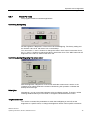
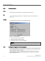
Commissioning
Service and maintenance
Alarm, error, and system
messages
05/2010
5
A
B
Legal information
Warning notice system
This manual contains notices you have to observe in order to ensure your personal safety, as well as to prevent
damage to property. The notices referring to your personal safety are highlighted in the manual by a safety alert
symbol, notices referring only to property damage have no safety alert symbol. These notices shown below are
graded according to the degree of danger.
DANGER
indicates that death or severe personal injury will result if proper precautions are not taken.
WARNING
indicates that death or severe personal injury may result if proper precautions are not taken.
CAUTION
with a safety alert symbol, indicates that minor personal injury can result if proper precautions are not taken.
CAUTION
without a safety alert symbol, indicates that property damage can result if proper precautions are not taken.
NOTICE
indicates that an unintended result or situation can occur if the corresponding information is not taken into
account.
If more than one degree of danger is present, the warning notice representing the highest degree of danger will
be used. A notice warning of injury to persons with a safety alert symbol may also include a warning relating to
property damage.
Qualified Personnel
The product/system described in this documentation may be operated only by personnel qualified for the specific
task in accordance with the relevant documentation for the specific task, in particular its warning notices and
safety instructions. Qualified personnel are those who, based on their training and experience, are capable of
identifying risks and avoiding potential hazards when working with these products/systems.
Proper use of Siemens products
Note the following:
WARNING
Siemens products may only be used for the applications described in the catalog and in the relevant technical
documentation. If products and components from other manufacturers are used, these must be recommended
or approved by Siemens. Proper transport, storage, installation, assembly, commissioning, operation and
maintenance are required to ensure that the products operate safely and without any problems. The permissible
ambient conditions must be adhered to. The information in the relevant documentation must be observed.
Trademarks
All names identified by ® are registered trademarks of the Siemens AG. The remaining trademarks in this
publication may be trademarks whose use by third parties for their own purposes could violate the rights of the
owner.
Disclaimer of Liability
We have reviewed the contents of this publication to ensure consistency with the hardware and software
described. Since variance cannot be precluded entirely, we cannot guarantee full consistency. However, the
information in this publication is reviewed regularly and any necessary corrections are included in subsequent
editions.
Siemens AG
Industry Sector
Postfach 48 48
90026 NÜRNBERG
GERMANY
A5E02722710-01
Ⓟ 05/2010
Copyright © Siemens AG 2010.
Technical data subject to change
Preface
Overview
Purpose of this manual
These operating instructions contain all the information you need for commissioning and
operating the SIMATIC IPC677C.
It is intended both for programming and testing personnel who commission the device and
connect it with other units (automation systems, programming devices), as well as for service
and maintenance personnel who install add-ons or carry out fault/error analyses.
Basic knowledge required
A solid background in personal computers and Microsoft operating systems is required to
understand this manual. General knowledge in the field of automation control engineering is
recommended.
Scope of this manual
This manual applies to devices with order numbers 6AV780.…
Approvals
For more information, please refer to the chapter "Certificates and Guidelines" in the
appendix.
CE marking
For more information, please refer to "Directives and Declarations" in the "Certificates and
Guidelines" section of the appendix.
Standards
Please refer to sections "Application planning" and "Technical data".
Position in the information landscape
The documentation for the Panel PC includes the following sections:
● SIMATIC HMI IPC677C, Operating Instructions (compact), with the following information:
– Commissioning
– Legal information
● SIMATIC HMI IPC677C, Operating Instructions
The documentation is supplied with the Panel PC in electronic form as a PDF file on the
"Documentation and Drivers" CD. The documentation is available in German, English,
French, Italian, Spanish, and Chinese.
SIMATIC IPC677C
Operating Instructions, 05/2010, A5E02722710-01
3
Preface
Conventions
Representation
Validity
"File"
Terminology that appears in the user interface, for example
menu commands, tabs, buttons
Required input, for example limit values, tag values
Path information
"File > Edit"
Operational sequences, for example, menu commands, shortcut
menu commands
<F1>, <Shift>+<F1>
Keys and key combinations
The "IPC677C", "control unit" and "computer unit" are uniformly referred to as "device" in
these operating instructions. The full term is only used when a concrete reference is
necessary.
Furthermore, the "CP 1616 onboard" is referred to as "CP".
Note
A note is important information about the product, handling the product or a reference to
specific sections of the documentation that require special consideration.
Trademarks
All names labeled with ® symbol are registered trademarks of Siemens AG. Other names
used in this documentation may be trademarks, the use of which by third parties for their
own purposes could violate the rights of the owner.
HMI®
SIMATIC®
SIMATIC HMI®
SIMATIC WinCC®
SIMATIC WinCC flexible®
Panel PC 677B®
IPC677C®
4
SIMATIC IPC677C
Operating Instructions, 05/2010, A5E02722710-01
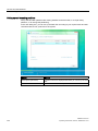
Table of contents
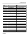
Preface ...................................................................................................................................................... 3
1
2
3
4
5
Safety ...................................................................................................................................................... 11
1.1
Safety guidelines..........................................................................................................................11
1.2
General Information .....................................................................................................................12
1.3
ESD directives..............................................................................................................................15
Description............................................................................................................................................... 17
2.1
Design of IPC677C ......................................................................................................................17
2.2
Characteristics of IPC677C..........................................................................................................18
2.3
Accessories of IPC677C ..............................................................................................................20
Planning the use ...................................................................................................................................... 21
3.1
Overview ......................................................................................................................................21
3.2
Unpacking and checking the delivery ..........................................................................................21
3.3
Device identification data .............................................................................................................22
3.4
Mounting positions and fastening ................................................................................................23
3.4.1
Installation guidelines...................................................................................................................23
3.4.2
Installation information stainless steel front .................................................................................25
3.4.3
Permitted mounting positions.......................................................................................................25
3.4.4
Type of fixation.............................................................................................................................26
3.4.5
Stainless steel front type of fixation .............................................................................................26
3.4.6
Protection against dust and water ...............................................................................................26
3.5
Mounting cutout ...........................................................................................................................27
3.5.1
Preparing the mounting cut-out....................................................................................................27
3.5.2
Mounting depth of the device.......................................................................................................28
3.6
EMC Guideline .............................................................................................................................29
Mounting.................................................................................................................................................. 31
4.1
Securing the device with clamps..................................................................................................31
4.2
Securing with screws ...................................................................................................................32
4.3
Fix the device with stainless steel front using clamps .................................................................33
Connecting .............................................................................................................................................. 35
5.1
Connection elements ...................................................................................................................35
5.2
Connecting the 100 - 240 V AC Power Supply............................................................................37
5.3
Connecting the (24 V) DC power supply .....................................................................................40
5.4
Connecting the Equipotential Bonding Circuit .............................................................................41
5.5
Equipotential bonding with stainless steel front ...........................................................................42
5.6
Connecting Ethernet/USB strain relief .........................................................................................42
5.7
Connecting the PROFINET strain relief.......................................................................................43
5.8
Connecting the power plug locking mechanism ..........................................................................43
SIMATIC IPC677C
Operating Instructions, 05/2010, A5E02722710-01
5
Table of contents
6
7
8
6
Integration into an automation system ..................................................................................................... 45
6.1
Overview ..................................................................................................................................... 45
6.2
6.2.1
6.2.2
Device in SIMATIC S7 network................................................................................................... 46
MPI/PROFIBUS-DP network....................................................................................................... 46
Connecting an S7 automation system ........................................................................................ 46
6.3
Transferring authorizations ......................................................................................................... 47
6.4
Networking via Industrial Ethernet .............................................................................................. 47
6.5
PROFINET .................................................................................................................................. 48
Commissioning ........................................................................................................................................ 51
7.1
Overview ..................................................................................................................................... 51
7.2
Switching on the device .............................................................................................................. 51
7.3
Windows XP, Windows 7 Security Center .................................................................................. 52
7.4
Setting up the Microsoft Windows operating system .................................................................. 52
7.5
7.5.1
7.5.2
Additional applications ................................................................................................................ 53
Touch Panel set-up ..................................................................................................................... 54
Key Panel adjustment ................................................................................................................. 55
7.6
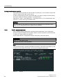
BIOS settings .............................................................................................................................. 56
7.7
USB ............................................................................................................................................. 56
7.8
7.8.1
7.8.2
7.8.3
7.8.4
Notes on operation...................................................................................................................... 57
DVD burner ................................................................................................................................. 57
2HDD system (optional) .............................................................................................................. 57
RAID1 system (optional) ............................................................................................................. 58
Compact Flash card (optional).................................................................................................... 60
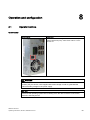
Operation and configuration..................................................................................................................... 63
8.1
Operator Controls........................................................................................................................ 63
8.2
8.2.1
8.2.2
8.2.3
Normal operation......................................................................................................................... 64
Switching on the device .............................................................................................................. 64
Logging on to the operating system using the on-screen keyboard ........................................... 65
Switching off the device .............................................................................................................. 66
8.3
8.3.1
8.3.2
8.3.3
8.3.4
8.3.5
8.3.6
8.3.7
8.3.8
8.3.9
8.3.10
Additional drivers and applications ............................................................................................. 66
Standard calibration procedure................................................................................................... 67
Activate touch functionality.......................................................................................................... 68
Extended Touch touch functionality ............................................................................................ 68
Deactivate touch functionality ..................................................................................................... 69
KeyTools (for key panel devices)................................................................................................ 70
On-screen keyboard (for touch panel device)............................................................................. 70
Panel PC Tools ........................................................................................................................... 71
CheckLanguageID ...................................................................................................................... 72
Multilingual settings for the operating system ............................................................................. 72
USB keyboard controller ............................................................................................................. 73
SIMATIC IPC677C
Operating Instructions, 05/2010, A5E02722710-01
Table of contents
9
10
11
Operation................................................................................................................................................. 75
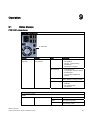
9.1
Status displays .............................................................................................................................75
9.2
9.2.1
9.2.2
9.2.3
9.2.3.1
9.2.3.2
9.2.3.3
9.2.4
9.2.5
9.2.6
Device with key panel ..................................................................................................................76
Safety ...........................................................................................................................................76
Overview ......................................................................................................................................76
Keys .............................................................................................................................................77
Control keys .................................................................................................................................77
Alphanumeric and numeric keys..................................................................................................77
Cursor keys ..................................................................................................................................79
External keyboards ......................................................................................................................79
Labelling function keys and softkeys ...........................................................................................79
Using the integrated mouse .........................................................................................................81
9.3
9.3.1
Device with touch panel ...............................................................................................................81
Operating a touch panel...............................................................................................................82
Functions ................................................................................................................................................. 85
10.1
Introduction ..................................................................................................................................85
10.2
Temperature monitoring...............................................................................................................85
10.3
Watchdog (WD)............................................................................................................................86
10.4
Fan monitoring .............................................................................................................................87
10.5
SRAM buffer memory ..................................................................................................................87
10.6
Battery monitoring........................................................................................................................87
Service and maintenance ........................................................................................................................ 89
11.1
Maintenance.................................................................................................................................89
11.2
Maintenance and care of devices with stainless steel front.........................................................90
11.3
Chemical resistance of stainless steel fronts...............................................................................92
11.4
Handling of stainless steel surfaces ............................................................................................92
11.5
Spare parts...................................................................................................................................93
11.6
Separating the control unit from the computer unit......................................................................94
11.7
11.7.1
11.7.2
11.7.2.1
11.7.3
11.7.3.1
11.7.3.2
11.7.4
11.7.4.1
11.7.4.2
11.7.4.3
11.7.4.4
11.7.4.5
11.7.5
11.7.6
Expansion and parameter assignment ........................................................................................96
Opening the Device .....................................................................................................................96
Memory expansion.......................................................................................................................97
Removing/Installing Memory Module...........................................................................................97
Installing PCI/PCIe cards .............................................................................................................99
Notes on the modules ..................................................................................................................99
Installing / removing expansion modules.....................................................................................99
Installing drives ..........................................................................................................................101
Options of installing disk drives..................................................................................................101
Installing/removing a drive bay module .....................................................................................102
Removing / installing an optical drive ........................................................................................103
Installing / removing hard disks..................................................................................................104
Removing/installing an SSD drive .............................................................................................105
Installing/removing an on-board Compact Flash card ...............................................................106
Installing/removing an additional Compact Flash card ..............................................................108
11.8
11.8.1
Removing and installing hardware components ........................................................................110
Repairs.......................................................................................................................................110
SIMATIC IPC677C
Operating Instructions, 05/2010, A5E02722710-01
7
Table of contents
12
13
14
15
8
11.8.2
11.8.3
11.8.4
11.8.5
11.8.6
11.8.7
11.8.8
11.8.9
Preventive maintenance............................................................................................................ 111
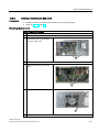
Replacing the Backup Battery................................................................................................... 111
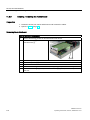
Removing/Installing the Power Supply ..................................................................................... 114
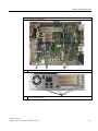
Installing / removing the bus board ........................................................................................... 115
Installing / removing the motherboard....................................................................................... 116
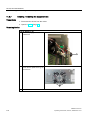
Installing / removing the equipment fan .................................................................................... 118
Installing / removing the power supply fan................................................................................ 119
Processor replacement ............................................................................................................. 120
11.9
11.9.1
11.9.1.1
11.9.1.2
11.9.2
11.9.2.1
11.9.2.2
11.9.3
11.9.3.1
11.9.3.2
11.9.4
11.9.4.1
11.9.4.2
11.9.4.3
11.9.5
11.9.5.1
11.9.6
11.9.6.1
11.9.6.2
11.9.7
11.9.7.1
11.9.8
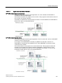
Installing the software ............................................................................................................... 121
Reinstalling the operating system ............................................................................................. 121
Windows Embedded Standard 2009 ........................................................................................ 121
Windows XP Professional / 7 Ultimate...................................................................................... 122
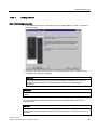
Partitioning data media ............................................................................................................. 126
Setting up the partitions under Windows XP Embedded .......................................................... 126
Setting up partitions under Windows XP Professional / Windows 7 Ultimate........................... 127
Installing drivers and software .................................................................................................. 127
Installing drivers and software .................................................................................................. 127
Driver installation under Windows Embedded Standard 2009 ................................................. 128
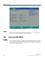
RAID1 system setup ................................................................................................................. 128
Settings in the BIOS setup and RAID ROM option................................................................... 128
Replacing a defective drive in the RAID system ....................................................................... 129
Installing the RAID Controller software ..................................................................................... 131
Installing burner software .......................................................................................................... 131
Installing the burner software .................................................................................................... 131
Installing updates ...................................................................................................................... 131
Updating the operating system ................................................................................................. 131
Installing or updating application programs and drivers ........................................................... 132
Data backup .............................................................................................................................. 132
Creating an image..................................................................................................................... 132
CP 1616 onboard ...................................................................................................................... 132
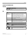
Alarm, error, and system messages ...................................................................................................... 133
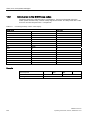
12.1
Boot error messages................................................................................................................. 133
12.2
Introduction to the BIOS beep codes ........................................................................................ 134
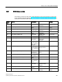
12.3
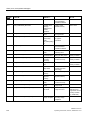
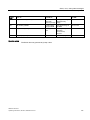
BIOS beep codes ...................................................................................................................... 135
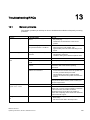
Troubleshooting/FAQs........................................................................................................................... 143
13.1
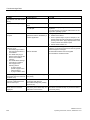
General problems...................................................................................................................... 143
13.2
Problems when Using Modules of Third-party Manufacturers.................................................. 145
13.3
Display a temperature error by means of the DiagBase application ........................................ 145
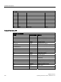
Technical data ....................................................................................................................................... 147
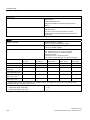
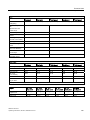
14.1
General specifications............................................................................................................... 147
14.2
Ports and status displays .......................................................................................................... 152
14.3
Current/power requirements of the device................................................................................ 153
14.4
AC voltage supply ..................................................................................................................... 154
14.5
DC power supply....................................................................................................................... 155
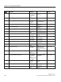
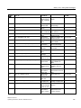
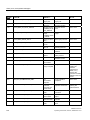
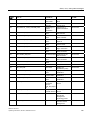
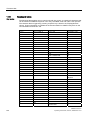
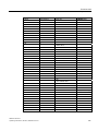
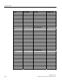
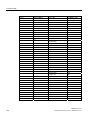
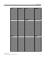
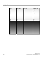
14.6
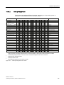
Keyboard table .......................................................................................................................... 156
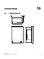
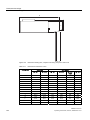
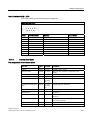
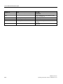
Dimensional drawings............................................................................................................................ 163
15.1
Dimension drawing IPC............................................................................................................. 163
15.2
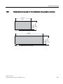
Dimensional drawings for the installation of expansion modules ............................................. 165
SIMATIC IPC677C
Operating Instructions, 05/2010, A5E02722710-01
Table of contents
16
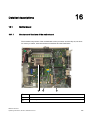
Detailed descriptions ............................................................................................................................. 167
16.1
Motherboard...............................................................................................................................167
16.1.1 Structure and functions of the motherboard ..............................................................................167
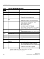
16.1.2 Technical features of the motherboard ......................................................................................168
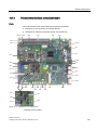
16.1.3 Position of the interfaces on the motherboard ...........................................................................169
16.1.4 External ports .............................................................................................................................170
16.1.5 Internal interfaces ......................................................................................................................175
16.1.6 Front ports..................................................................................................................................177
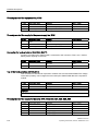
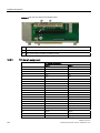
Bus board...................................................................................................................................181
16.2
16.2.1 Layout and principle of operation...............................................................................................181
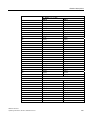
16.2.2 PCI slot pin assignment .............................................................................................................182
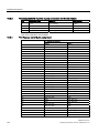
16.2.3 Pin assignment 12 V power supply connection for WinAC module...........................................184
16.2.4 PCI Express slot x16 pin assignment ........................................................................................184
16.3
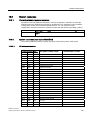
System resources ......................................................................................................................185
16.3.1 Currently allocated system resources........................................................................................185
16.3.2 System resources used by the BIOS/DOS ................................................................................185
16.3.2.1 I/O address allocation ................................................................................................................185
16.3.2.2 Interrupt Assignments ................................................................................................................187
16.3.2.3 Exclusive PCI hardware interrupt...............................................................................................188
16.3.2.4 Memory address assignments ...................................................................................................189
16.4
BIOS Setup ................................................................................................................................190
16.4.1 Overview ....................................................................................................................................190
16.4.2 Starting BIOS Setup...................................................................................................................190
16.4.3 BIOS Setup menus ....................................................................................................................191
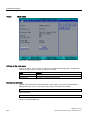
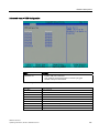
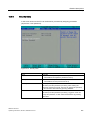
16.4.4 Main menu .................................................................................................................................192
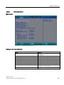
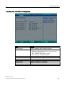
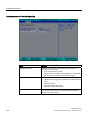
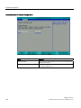
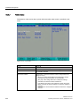
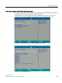
16.4.5 Advanced menu .........................................................................................................................193
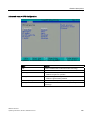
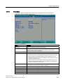
16.4.6 Security menu ............................................................................................................................201
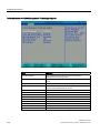
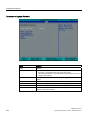
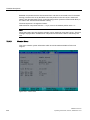
16.4.7 Power menu ...............................................................................................................................202
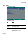
16.4.8 Boot Menu..................................................................................................................................203
16.4.9 Version Menu .............................................................................................................................206
16.4.10 Exit menu ...................................................................................................................................207
16.4.11 BIOS Setup default settings.......................................................................................................208
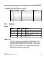
16.5
Communications processor CP 1616 onboard ..........................................................................212
16.5.1 Introduction ................................................................................................................................212
16.5.1.1 Properties...................................................................................................................................212
16.5.1.2 Network connections..................................................................................................................212
16.5.1.3 Typical Communication Partners ...............................................................................................213
16.5.2 Firmware loader .........................................................................................................................214
16.5.2.1 Loading firmware .......................................................................................................................215
16.5.3 Further actions in STEP 7/NCM PC ..........................................................................................216
A
Appendix................................................................................................................................................ 217
A.1
Certificates and guidelines.........................................................................................................217
A.1.1
Guidelines and declarations.......................................................................................................217
A.1.2
Standards, certificates and approvals........................................................................................218
B
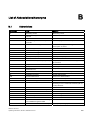
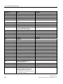
List of Abbreviations/Acronyms.............................................................................................................. 223
B.1
Abbreviations .............................................................................................................................223
Glossary ................................................................................................................................................ 227
Index...................................................................................................................................................... 233
SIMATIC IPC677C
Operating Instructions, 05/2010, A5E02722710-01
9
Table of contents
10
SIMATIC IPC677C
Operating Instructions, 05/2010, A5E02722710-01
1
Safety
1.1
Safety guidelines
WARNING
Emergencies
In the event of a device fault, interrupt the power supply immediately. Inform the customer
service personnel responsible. Malfunctions can occur when the operator controls or power
cable are damaged or when liquids or foreign objects penetrate the device.
WARNING
Following the results of a risk analysis, additional protection equipment on the machine or
the system is necessary to avoid endangering persons. With this, especially the
programming, configuration and wiring of the inserted I/O modules have to be executed, in
accordance with the safety performance (SIL, PL or Cat.) identified by the necessary risk
analysis. The intended use of the device has to be ensured.
The proper use of the device has to be verified with a function test on the system. This test
can detect programming, configuration and wiring errors. The test results have to be
documented and, if necessary, entered into the relevant documents that verify safety.
Note
This device corresponds to the regulations of the EU low-voltage directive and the GPSG,
verified by conformity with national and international standards (DIN EN, IEC) by a UL
approval (cULuc). Please comply with all the information in these operating instructions
when assembling the device.
Electrical connection
WARNING
Disconnect the device from the mains before every intervention.
Do not touch power lines or data transmission lines during electrical storms and do not
connect any cables.
System expansions
Only install system expansion devices designed for this device. If you install other
expansions, you may damage the system or violate the safety requirements and regulations
for radio frequency interference suppression. Contact your technical support team or where
you purchased your PC to find out which system expansion devices may safely be installed.
CAUTION
If you install or exchange system expansions and damage your device, the warranty
becomes void.
SIMATIC IPC677C
Operating Instructions, 05/2010, A5E02722710-01
11
Safety
1.2 General Information
High frequency radiation
CAUTION
Unintentional operating situations
High frequency radiation, from cell phones for example, can cause unintentional operating
situations under some circumstances. Further information is available in the section "EMC
requirements" of the "Technical data" chapter.
Handling and disposal of lithium batteries
WARNING
Danger of explosion and the release of harmful substances!
Do not throw lithium batteries into fire, do not solder onto the cell body, do not open, do not
short circuit, do not reverse pole, do not heat above 100 °C, dispose of according to
regulations, and protect from direct sunlight, moisture and condensation.
Replace lithium batteries with the same brand or a brand recommended by the
manufacturer.
Dispose of used lithium batteries as hazardous waste, individually, in accordance with the
local regulations.
Repairs
Only authorized personnel are permitted to repair the device.
WARNING
Unauthorized opening of and improper repairs to the device may result in substantial
damage to equipment or risk of personal injury to the user.
1.2
General Information
Overview
CAUTION
The device must only be operated in closed rooms. Failure to comply nullifies the warranty.
Operate the device only in accordance with the ambient conditions specified in the technical
specifications. Protect the device against dust, moisture and heat. Do not place the device in
direct sunlight.
12
SIMATIC IPC677C
Operating Instructions, 05/2010, A5E02722710-01
Safety
1.2 General Information
Transport
Unpack the device at its installation location. Transport the device only in the original
packaging. Do not transport the device when it is mounted.
NOTICE
Adhere to these stipulations each time the device is transported, otherwise the guarantee is
void.
CAUTION
Condensation
When transporting the device at low temperatures, ensure that no moisture gets on or into
the device. This also applies if the device is subjected to extreme changes in temperature.
Commissioning
Allow the device to slowly adjust to room temperature before commissioning the device. Do
no place the device near heat radiation. If moisture condensation occurs, wait at least 12
hours before you switch on the device.
Vibration
Optical drives are sensitive to vibration. Inadmissible vibration during operation may result
in loss of data or damage to the drive or data medium.
Before transporting the device, wait at least 20 seconds to allow the drive to stop
completely.
Tools & downloads
Please check regularly if updates and hotfixes are available for download to your device.
Downloads are available on the Internet at "Support". http://www.siemens.com/asis
(https://www.automation.siemens.com/Industrial-PC/html_76/support/asis.htm).Under
"ASIS", click on "Drivers and Bios Updates" and select the device family. Alternatively, click
on "Downloads" at "Tools & Downloads". You can use "Search terms" to search for the
required download.
Optical drive
NOTICE
An optical drive should only be operated in a mechanically undisturbed environment without
vibrations and shock and at a temperature of < 40°C.
Safety-relevant applications
WARNING
Maloperation
Do not perform safety-relevant functions of the user software with the touch screen.
SIMATIC IPC677C
Operating Instructions, 05/2010, A5E02722710-01
13
Safety
1.2 General Information
Resistance to chemicals
CAUTION
Adhere to the information regarding chemical resistance of the panel front. For additional
information, refer to the Internet at "Technical Support
(http://support.automation.siemens.com)". Enter the article ID 22591016 in the "Search for
product information". The available article is displayed.
Sources of light
NOTICE
Position the screen so that it is not subject to direct sunlight or other strong sources of light.
Defective pixels in the display
At present, the manufacturing process of modern displays does not guarantee that all pixels
of the display will be perfect. A small number of defective pixels in the display is therefore
unavoidable. This does not present a functional problem as long as the defective pixels are
not bunched in one location.
Further information is available in the section "General technical data" of the "Technical
data" chapter.
Backlighting
The brightness of the backlighting decreases incrementally during its operational life. In
order to not shorten the operational lifetime of the backlighting unnecessarily, activate the
backlighting reduction.
Burn-in effect on TFT displays
An image may occasionally leave a burn-in effect in the background if it appears too long on
the screen. This burn-in effect will automatically disappear after a certain amount of time if,
for example, the screen saver is activated. The longer the same image is displayed on the
screen, the longer it will take for the burn-in effect to disappear.
Screen saver
Generally, you should always activate the screen saver. If a screen saver is activated,
please observe the following:
● The liquid crystals in screen savers which actuate active black when the backlighting is
on renew themselves. Pay attention to the length of time the backlighting is activated.
● Screen savers that reduce the backlighting extend the life span of the backlighting.
● Screen savers that switch off the backlighting shorten the life span of the backlighting.
Consider the following carefully:
● Screen saver
● Switch off the backlighting regularly
● Permanent display of the customer application
14
SIMATIC IPC677C
Operating Instructions, 05/2010, A5E02722710-01
Safety
1.3 ESD directives
1.3
ESD directives
What does ESD mean?
Almost all electronic modules are equipped with highly integrated components and elements
in MOS technology. For technological reasons, these electronic components are very
sensitive to overvoltages and, consequently, to electrostatic discharge. These components
are therefore marked as follows:
● ESD: Electrostatically Sensitive Devices
● ESD: Internationally recognized marking for components and modules susceptible to
electrostatic discharge
The following symbols on switch cabinets, module carriers or packaging indicate their
susceptibility to electrostatic discharge:
ESD components are destroyed by voltage and energy far below the limits of human
perception. Voltages of this kind occur as soon as a device or an assembly is touched by a
person who is not electrostatically discharged ESD components which were subject to such
voltage are usually not recognized immediately as being defective, because the malfunction
does not occur until after a longer period of operation.
Note
More information is located on the rating label. The rating label is described in the chapter
"Planning use."
Precautions against electrostatic discharge
Most plastics can be charged easily. Therefore, keep plastics away from ESD components!
When working with electrostatically sensitive components, make sure that the person, the
workstation and the packaging are properly grounded. Conduct the electrostatic charge
away from your body by touching the mounting plate for the interfaces, for example.
Handling ESD modules
As a rule: Only touch ESD components if unavoidable due to necessary tasks.
Only touch the components when the following holds true:
● You are permanently grounded by means of an ESD armband.
● You are wearing ESD shoes or ESD shoes grounding protective strips in connection with
ESD floors.
Before you touch an electronic assembly, your body must be discharged. Touch a
conductive object immediately beforehand, e.g. a bare metal part of a switch cabinet or the
water pipe.
SIMATIC IPC677C
Operating Instructions, 05/2010, A5E02722710-01
15
Safety
1.3 ESD directives
Do not allow chargeable, highly insulated materials, e.g. plastic films, insulating tabletops,
synthetic clothing fibers, to come into contact with ESD components.
Place ESD components only on conductive surfaces (work surfaces with ESD surface,
conductive ESD foam, ESD packing bag, ESD transport container).
Do not expose ESD components to visual display units, monitors or televisions. Maintain a
distance of at least 10 cm to screens.
Handle flat components only by their edges. Do not touch component connectors or
conductors. This prevents charges from reaching and damaging sensitive components.
Measuring and modifying ESD components
Measure the ESD component under the following conditions only:
● The measuring device is grounded with a protective conductor, for example.
● The probe on the potential-free measuring device has been discharged, e.g. by touching
the bare metal of a part of the switch cabinet.
● Your body is discharged. To do so, touch a grounded metallic object.
Solder only with grounded soldering irons.
Shipping ESD modules
Always store or ship ESD components in conductive packaging, e.g. metallized plastic boxes
or metal cans. Leave the components and parts in their packaging until installation.
If the packaging is not conductive, wrap the ESD component in a conductive material, e.g.
rubber foam, ESD bag, household aluminum foil, or paper, before packing. Do not wrap the
ESD component in plastic bags or plastic film.
In ESD components containing installed batteries, make sure that the conductive packaging
does not touch the battery connectors or short circuit. Insulate the connectors with suitable
material.
16
SIMATIC IPC677C
Operating Instructions, 05/2010, A5E02722710-01
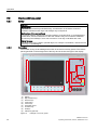
2
Description
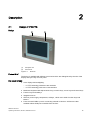
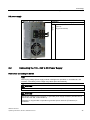
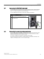
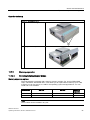
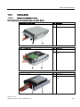
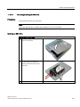
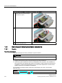
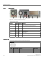
2.1
Design of IPC677C
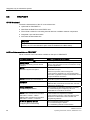
Design
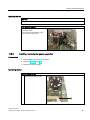
(1)
Computer unit
(2)
Control unit
Figure 2-1
IPC677C
Product Brief
The device is available with different control units which are distinguished by the size of the
display and by the key or touch panel.
Key panel variants
● Color display with backlighting:
– 12'' TFT technology with 800 x 600 resolution
– 15'' TFT technology with 1024 x 768 resolution
● Membrane keyboard with alphanumeric keys, numeric keys, cursor keys and control keys
● Function keys and softkeys
● Integrated mouse
● LEDs for power supply, temperature, softkeys, <Shift> and <ACK> function keys and
buttons
● Front-mounted USB 2.0 port for connecting external I/O devices. All fronts are also
available without USB port accessible from the front
SIMATIC IPC677C
Operating Instructions, 05/2010, A5E02722710-01
17
Description
2.2 Characteristics of IPC677C
Key panel variants
● Color display with backlighting
– 12" TFT technology; 800 x 600 resolution
– 15" TFT technology; 1024 x 768 resolution
– 15" TFT technology; resolution 1024 x 768 pixels, with stainless steel front INOX
– 19" TFT technology; 1280 x 1024 resolution
● LEDs for power supply and temperature
● Front-mounted USB 2.0 port for connecting external I/O devices (except INOX). All fronts
are also available without USB port accessible from the front.
Refer to the "Specifications" section for more information.
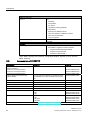
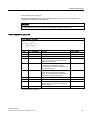
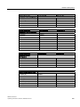
2.2
Characteristics of IPC677C
Basic data
Design
Panel mounting device, computer unit
Processor
Intel® Celeron™ P4505 mobile processor 1.86 GHz,
2 MB second-level cache, 2 cores / 2 threads
Intel® Core™ i3-330E mobile processor 2.13 GHz,
3 MB second-level cache, 2 cores /4 threads,
hyperthreading, virtualization
Intel® Core™ i7-610E mobile processor 2.53 GHz,
4 MB second-level cache, 2 cores /4 threads,
hyperthreading, turboboost and virtualization
Chipset
Mobile Intel® QM57 Express Chipset
Main memory
1 GB SDRAM (DDR3)
Expandable up to 4 GB SDRAM (DDR3)
ECC, optional
Slots for add-ons
1x PCI 290 mm long and 1x PCI 185 mm long
1x PCI 290 mm long and 1x PCI Express x16 185 mm
long
Graphics
Intel® HD graphics controller,
chip set integrated 2-D and 3-D engine,
Dynamic Video Memory Technology
(uses up to 256 MB RAM)
CRT:
Max. 1280x1024 at 100 Hz / 32-bit color depth
Max. 1600x1200 at 60 Hz / 32-bit color depth
Maximum resolution:
2038x1536 at 75 Hz / 16-bit color depth
LCD via DVI-I: 1600x1200 at 60 Hz / 32-bit color depth
120 V / 230 V AC, 190 W; varying voltage
24 V DC, 210 W
Power supply
Both with bridging of transient loss of voltage according to
NAMUR: Max. 20 ms at 0.85 rated voltage.
The 24V DC power supply is protected against reversed
polarity.
18
SIMATIC IPC677C
Operating Instructions, 05/2010, A5E02722710-01
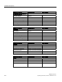
Description
2.2 Characteristics of IPC677C
Basic data
Drives and storage media
1 x 3.5" hard disk or
2 x 2.5" hard disk or RAID1 system
Capacity see order forms
Mass storage
DVD drive
DVD burner
Flash memory
Slot for Compact Flash card
1 x Solid State Disk
Ports
Ethernet
2x 10/100/1000 Mbps (RJ45)
PROFIBUS/MPI
12 Mbps (isolated potential, compatible to CP 5611),
optional
PROFINET
10/100 Mbps (CP 1616 onboard), three RJ45; optional
USB
External: 4x USB 2.0 high current
(max. 2 can be simultaneously operated as high current)
Internal: 1x USB 2.0 high current + 1x USB 2.0 low
current on a 10-pole male connector, 1x USB 2.0 low
current for internal USB stick/dongle
Front ports: 1x USB 1.1, 1x USB 2.0,
both high current
COM
Serial V.24 port
Monitor
1x DVI-I (VGA monitors can be connected with a DVI/VGA
adapter that is available as an accessory)
Monitoring and safety functions
Temperature
When permitted temperature range is exceeded
Warning messages from application program that can
be analyzed: local (DiagBase), via LAN (DiagMonitor,
optionally available)
Fans
Failure of device and power supply fans
Warning messages from application program that can
be analyzed: local (DiagBase), via LAN (DiagMonitor,
optionally available)
Watchdog
Monitoring function for program execution
Restart can be parameterized in the event of a fault
Warning messages from application program that can
be analyzed: local (DiagBase), via LAN (DiagMonitor,
optionally available)
LED display
2 LEDs for displaying system status that can be
programmed by the user1
Transient voltage interruption
Up to 20 ms buffer time with full load
Buffer memory (optional)
2 MB battery-buffered SRAM1)
1)Contact
Customer Support for information about addressing the LEDs or the SRAM under a
Windows operating system.
SIMATIC IPC677C
Operating Instructions, 05/2010, A5E02722710-01
19
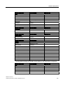
Description
2.3 Accessories of IPC677C
Optional expansions
SIMATIC PC DiagMonitor software
≥ V 4.2
Software tool for monitoring local and remote SIMATIC
PCs:
Watchdog
Temperature
Fan speed
Hard disk monitoring (SMART)
Communication:
Ethernet port (SNMP protocol)
OPC for integration in SIMATIC software
Client server architecture
Layout of log files
SIMATIC IPC Image & Partition Creator
Software tool for local data backup and partitioning of
hard disks
Software
Operating systems
Without
Preinstalled / supplied on restore CD/DVD:
– Windows Embedded Standard 2009
–
English on CompactFlash
Windows 7 Ultimate MUI 1)
1) MUI:
Multi Language User Interface; 6 languages (English, German, French, Spanish,
Italian, Chinese)
2.3
Accessories of IPC677C
Accessories
Comment
Order No.
Film for protecting the touch panel against
dirt and scratches
for the 12" touch panel version
for the 15" touch panel version
for the 19" touch panel version
Film for labeling the function keys
(slide-in labels)
6AV7671-2BA00-0AA0
6AV7671-4BA00-0AA0
6AV7672-1CE00-0AA0
You can find print templates for the slide-in labels
are available on the "Documentation and Drivers"
CD.
Touch pen
6AV7672-0DA00-0AA0
6AV7672-1JB00-0AA0
DVI / VGA adapter
6ES7648-3AB00-0XA0
External USB disk drive
1 m connecting cable
6FC5235-0AA05-1AA1
PCI multi-I/O module
Provides one parallel and one serial port
6ES7648-2CA00-0AA0
SIMATIC PC Image Creator software
Software tool for saving data locally
6ES7648-6AA03-0YX0
Module for DDR2 RAM, DIMM expansion
512 MB
1 GB
2 GB
6ES7648-2AG30-0HA0
6ES7648-2AG40-0HA0
6ES7648-2AG50-0HA0
Module for DDR3 RAM, DIMM expansion
1 GB
2 GB
1 GB, ECC
2 GB, ECC
6ES7648-2AH40-0KA0
6ES7648-2AH50-0KA0
6ES7648-2AH40-1KA0
6ES7648-2AH50-1KA0
You can find ordering information on the Internet at: http://mall.automation.siemens.com.
20
SIMATIC IPC677C
Operating Instructions, 05/2010, A5E02722710-01
Planning the use
3.1
3
Overview
Introduction
This section describes the first steps after unpackaging, the permitted mounting positions
and the fixation. This section describes the necessary considerations for EMC.
Field of application
The Panel PC is an industry-standard PC platform for demanding tasks in the field of PCbased automation. The Panel PC is designed for on-site use on the machine, installed for
example in:
● Control cabinet installation
● Swivel arm mounting
● Rack mounting
Note
In the following, the term "switchgear cabinet" also refers to rack, mounting rack,
switchboard, operator panel and console. The term "device" represents the Panel PC and
its variants.
3.2
Unpacking and checking the delivery
Procedure
1. Please check the packaging material for transport damage upon delivery.
2. If any transport damage is present at the time of delivery, lodge a complaint at the
shipping company in charge. Have the shipper confirm the transport damage
immediately.
3. Unpack the device.
CAUTION
Do not lie the device on its back. This will avoid any damage to an optical drive which
may be present. Lie the front side on a soft surface to avoid damaging the front panel
USB port.
4. Keep the packaging material in case you have to transport the unit again.
SIMATIC IPC677C
Operating Instructions, 05/2010, A5E02722710-01
21
Planning the use
3.3 Device identification data
NOTICE
The packaging protects the device during transport and storage. Therefore, never
dispose of the original packaging material!
5. Please keep the enclosed documentation in a safe place. You will need the
documentation when you start up the device for the first time.
6. Check the package contents for completeness and any visible transport damage. Check
for completeness using the enclosed scope of delivery list.
7. Should the contents of the package be incomplete or damaged, please inform the
responsible supply service immediately and fax us the enclosed form "SIMATIC IPC/PG
quality control report".
WARNING
Make sure that a damaged device is not installed nor put into operation.
8. Note the identification information as described in the chapter "Identification data of the
device".
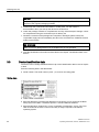
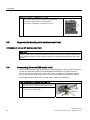
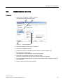
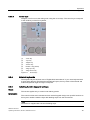
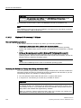
3.3
Device identification data
The device can be clearly identified with the help of this identification data in case of repairs
or theft.
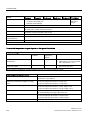
Enter the following data in the table below:
● Serial number: The serial number (S VP...) is found on the rating plate.
Rating plate
● Order number of the device
● Ethernet addresses: The Ethernet addresses of the device can be viewed in the BIOS
Setup (F2) under "Main > Hardware Options > Onboard Ethernet Address".
● Microsoft Windows "Product Key" on the "Certificate of Authenticity" (COA). The COA
label is bonded to the device. The Product Key is always required to reinstall the
operating system.
22
SIMATIC IPC677C
Operating Instructions, 05/2010, A5E02722710-01
Planning the use
3.4 Mounting positions and fastening
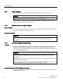
COA label
Serial number:
S VP ...
Order No.
6AV78.....
Microsoft Windows Product Key
Ethernet address 1
Ethernet address 2
3.4
Mounting positions and fastening
3.4.1
Installation guidelines
Before installing the device, read the following general notes relating to installation.
WARNING
Danger, high voltage
Isolate the power supply to the switchgear cabinet before opening it. Ensure that the power
to the switchgear cabinet cannot be turned on accidentally.
CAUTION
The device is approved for operation in closed rooms only.
● Ensure that the protective contact socket of the building installation is easily accessible
and that there is a mains disconnect switch in switchgear cabinet installations.
● Position the screen in an ergonomic position favorable to the user. Choose a suitable
installation height.
● Position the screen so that it is not subject to direct sunlight or other strong sources of
light.
● Optical drives are susceptible to shock. Shocks during operation can lead to the loss of
data or damage to the drive or data carrier. Optical drives are not only suitable for
continuous operation.
● Applies to devices which are installed in swivel arm housings: Avoid rapid or jerky
movements of the swivel arm during operation. The ensuing forces could lead to possible
irreversible damage of the hard disk.
The stops of the swivel arm must be damped in order to avoid any mechanical shock
effect to the Panel PC on attachment.
● Applies to devices which are installed in cabinet doors: Prevent the doors being slammed
shut. The ensuing forces could lead to possible irreversible damage of the hard disk.
SIMATIC IPC677C
Operating Instructions, 05/2010, A5E02722710-01
23
Planning the use
3.4 Mounting positions and fastening
● The computer unit together with its AC power supply satisfies the requirements for fire
protected enclosures according to EN 60950-1. Therefore it can be installed without any
additional fire protective covering.
● The computer unit with DC power supply does not fulfill the requirements according to
EN 60950-1 in the power supply unit area. The device must therefore be installed in such
a way that it is part of an operating area with restricted access (for example, a locked
switchgear cabinet, control panel or server room).
NOTICE
When using the device in the area of Industrial Control Equipment (UL 508), ensure that
it is classified as "Open Type". A mandatory requirement for approval or operation
according to UL 508 is therefore that the device be installed in an enclosure certified for
UL 508.
● Provide adequate volume in the switchgear cabinet for air circulation and heat transport.
Keep at least 10 cm distance between the device and switchgear cabinet.
● Make sure that the maximum air intake temperature is not exceeded (refer to the
"Technical specifications" chapter). The maximum air intake temperature must be
accounted for especially when sizing closed switchgear cabinets.
● The minimum distance between the device and the housing is 10 cm on the air output
side at the fan.
● Position the device in such a way that the air vents of the housing are not covered up
following mounting.
● Ensure there is enough free space in the switchgear cabinet to allow the sheet metal
cover to be removed. You will otherwise have to remove the device from the switchgear
cabinet or swivel arm when replacing memory or the battery.
● Equip the switchgear cabinet with struts for stabilizing the mounting cut-out. Install struts
where necessary.
● Avoid extreme environmental operating conditions. Protect your device against dust,
moisture and heat.
● The device is designed for use in normal industrial environments to IEC 60721-3-3
(pollutant class 3C2 for chemical influence, 3S2 for sand and dust.) The device may not
be operated in severe environments which are subject to caustic vapors or gases without
taking additional protective measures (such as the provision of clean air.)
● Install the device in such a way that it poses no danger, e.g. by falling over (see Chapter
"Technical Specifications").
● During assembly, please comply with the approved installation positions.
NOTICE
If you mount the device in an impermissible installation position or you do not observe
the environmental conditions (see Chapter "Specifications"), you endanger the product
safety provided by the UL-approval and compliance with the low-voltage directive (via
EN 60950-1). In additional, the functionality of the device is no longer guaranteed.
For additional information, refer to the dimension diagrams in the appendix.
24
SIMATIC IPC677C
Operating Instructions, 05/2010, A5E02722710-01
Planning the use
3.4 Mounting positions and fastening
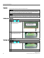
3.4.2
Installation information stainless steel front
Before you install the device, read the additional installation guidelines below:
● Make sure that you can access the device from the rear.
● The mounting cut-out should be deburred.
● When operating the device in a switch cabinet, ensure compliance with permitted ambient
conditions and, in particular, that permitted ambient temperatures are not exceeded.
Make allowances for the fact that the thermal conductivity of control cabinets made of
stainless steel is not as good as that of an aluminum cabinet, for example.
● Check the seal on the device. Always install the device with this seal.
● Always use the included clamping frame and clamps to mount the device.
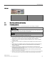
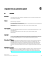
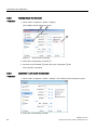
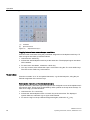
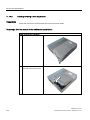
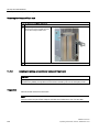
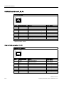
3.4.3
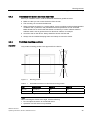
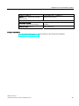
Approval
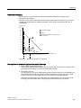
Permitted mounting positions
Only certain mounting positions are approved for the device.
˞
Figure 3-1
Mounting position
Table 3- 1
Permissible deviations from the vertical mounting position
TFT
Temperature
12"; 15"
up to 50
19"
up to 45 °C
1)
°C1)
Angle A
˟
Angle B
20°
20°
20°
20°
With a total loading of slots amounting to 15 W
Note
When mounting the device at an angle, note the following.
Do not subject the device to mechanical stress.
Operation of a DVD drive is not permitted.
SIMATIC IPC677C
Operating Instructions, 05/2010, A5E02722710-01
25
Planning the use
3.4 Mounting positions and fastening
3.4.4
Type of fixation
The computer unit is secured in the mounting cut-out either with clamps or screws.
NOTICE
Securing with screws is not possible with the 12" touch screen variant.
Select the type of fixation suitable to your requirements for the degree of protection (see
section "Protection against dust and water") .
3.4.5
Stainless steel front type of fixation
Type of fixation
The device is fastened with the included clamps. Additional fastening bore holes or threaded
bolts are not required for the control panel.
Degree of protection
CAUTION
Degree of protection IP66 is only ensured if the seal of the device is correctly positioned
and evenly pressed on the control panel. Refer to the "Installation" section for more
information.
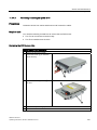
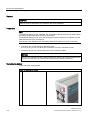
3.4.6
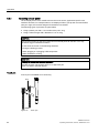
Protection against dust and water
Principle
With the relevant installation, the device is protected on the front against the ingress of dust
and water. The "degree of protection" is in accordance with IEC 60529: On the front, the
device has degree of protection IP65, the rear of the operator section and the computer unit
have degree of protection IP20.
CAUTION
Ensure that the material strength at the mounting cut-out is a minimum of 2 mm and a
maximum of 6 mm. Please follow the specifications for the dimensions in the "Mounting cutout" section.
The degrees of protection IP65, IP54 and Enclosure Type 4, are only guaranteed when the
following conditions are met:
The surface plane deviation of the mounting cut-out in relation to the external dimensions of
the control unit amounts to ≤ 0.5 mm when the control unit is mounted.
Degree of protection IP65 and Enclosure Type 4
The degrees of protection IP65 and Enclosure Type 4 are only provided for clamp mounting
together with a ring seal.
26
SIMATIC IPC677C
Operating Instructions, 05/2010, A5E02722710-01
Planning the use
3.5 Mounting cutout
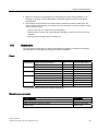
IP54 degree of protection
The IP54 degree of protection is applicable for the following conditions:
Key panel
Touch panel
12"
15"
15"
19"
X
X
X
-
Screw mounting
See also
Industry Mall (http://mall.automation.siemens.com)
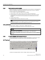
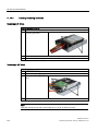
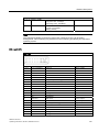
3.5
Mounting cutout
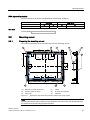
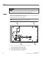
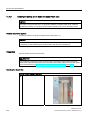
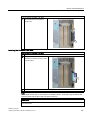
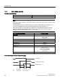
3.5.1
Preparing the mounting cut-out
The following illustration shows the dimensions for the mounting cut-out.
$
/
$
/
/
/
6
6
/
6
/
/
6 6
/
/
/
/
/
6
6
/
PP
/
(1)
Drill hole for screw attachment
(4)
Clamp
(2)
Pressure points for clamp
(5)
RZ 120 in the seal area
(3)
Setscrews
(6)
Seal area
Figure 3-2
Drill holes for the screws and pressure points for the clamp screws
Note
Mounting dimensions can be read from the dimension overview or they can be transferred to
the cabinet from the mounting template supplied.
SIMATIC IPC677C
Operating Instructions, 05/2010, A5E02722710-01
27
Planning the use
3.5 Mounting cutout
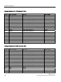
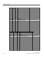
Table 3- 2
Dimensions for the mounting cut-out in mm
Control
unit
L1
L2
L3 1)
L4 1)
L5
L6 2)
L7 2)
L8 2)
L9 2)
A1
A2
S1
S2
S3
S4
S5 3)
S6 3)
S7 3)
Tolerance
±1
+1
±0.2
±0.2
±0.5
±0.5
±0.5
±0.5
+1
±1
±1
±1
±1
±1
±1
Touch
panel
12" TFT
15" TFT
15" TFT INOX
450
290
465
235
112
—
—
—
—
16
10
78
78
56
—
450
321
465
279
112
186
135
25
165
16
17
51
51
56
—
368
450
450
290
290
380
—
465
465
—
235
235
112
112
112
—
—
—
—
—
—
—
—
—
—
—
—
16
16
16
10
10
10
19
81
46
35
81
46
56
56
—
—
—
33
Touch
panel
12" TFT
15" TFT
19" TFT
1)
M6 thread or drill holes with a diameter of 7 mm
2)
Cut-outs for the shafts of the insert strips are only necessary for 15" key panels.
3)
Two clamps necessary for vertically securing clamps only for 19" touch panel fronts.
Preparing the mounting cut-out
Steps for preparing the mounting cut-out
3.5.2
1
Select a location suitable for mounting, taking into account the mounting position.
2
On the basis of the dimensions, check whether the required screw and pressure points on the
rear and the seal area are easily accessible after the completion of the mounting cut-out.
Otherwise the mounting cut-out is useless.
3
Complete the mounting cut-out in accordance with the dimensions.
Mounting depth of the device
7
28
SIMATIC IPC677C
Operating Instructions, 05/2010, A5E02722710-01
Planning the use
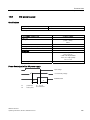
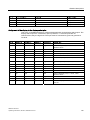
3.6 EMC Guideline
Panel PC with operator control units
Depth D
Key panel with 12" TFT
105 mm
Key panel with 15" TFT
124 mm
Touch panel with 12" TFT
123 mm
Touch panel with 15" TFT
121 mm
Touch panel with 15" TFT INOX
126 mm
Touch panel with 19" TFT
130 mm
Note
Additional mounting depth with optical drive
The installation depth increases by 21 mm when an optical drive is installed in the device.
3.6
EMC Guideline
Electromagnetic compatibility
The device fulfills the requirements of the EMC law of the Federal Republic of Germany as
well as the EMC directive of the Single European Market.
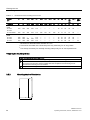
The device is designed as a built-in device. You can ensure compliance with the EN 610004-2 (ESD) EMC standard by installing the device in grounded metal cabinets (for example, 8
MC cabinets, Siemens catalog NV21).
Note
For additional information about EMC requirements, refer to the Specifications section.
Installing the device according to EMC directive
Basics for interference-free operation:
● Install the controller according to EMC directive
● Use interference immune cable
Note
The instructions "Guidelines for the assembly of interference immune programmable logic
controllers" with the article ID 1064706 and the manual "PROFIBUS networks" with the
article ID 1971286, which also applies to the installation of the device, is located on the
"Documentation and Drivers" CD.
SIMATIC IPC677C
Operating Instructions, 05/2010, A5E02722710-01
29
Planning the use
3.6 EMC Guideline
30
SIMATIC IPC677C
Operating Instructions, 05/2010, A5E02722710-01
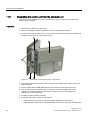
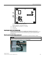
4
Mounting
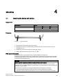
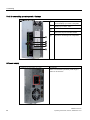
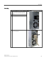
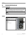
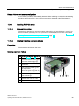
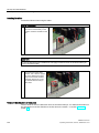
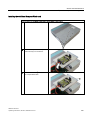
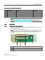
4.1
Securing the device with clamps
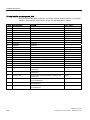
Requirement
Accessories
Display
12"
15"
19"
Clamp
6x
6x
8x
The clamps are provided with the control unit.
Tool
2.5 mm hexagonal spanner
Procedure
Figure 4-1
Clamp assembly
1. Disconnect the device from the power supply.
2. Working from the front, insert the device into the 19" rack on the swivel arm or in the
mounting cut-out.
3. Fasten the control unit from the rear using the clamps.
4. Tighten the setscrews to a torque of 0.4 - 0.5 Nm.
IP65 degree of protection
The plant builder is responsible for the correct installation of the device.
The degree of protection IP65 is only guaranteed for the front of the device if the ring seal is
properly applied with the correct size of cutout, the unit has been clamped in place, and the
instructions below are observed.
NOTICE
Control cabinet installation: Material strength at the mounting cut-out
Ensure that the material strength at the mounting cut-out is a minimum of 2 mm and a
maximum of 6 mm. Please follow the specifications for the dimensions in the "Preparing the
mounting cut-out" section.
The degrees of protection are only guaranteed when the following is observed:
The surface plane deviation of the mounting cut-out in relation to the external
dimensions of the control unit amounts to ≤ 0.5 mm when the control unit is mounted.
SIMATIC IPC677C
Operating Instructions, 05/2010, A5E02722710-01
31
Mounting
4.2 Securing with screws
4.2
Securing with screws
Note
Securing with screws is not possible with the 12" touch panel variant.
Drill holes in the control unit
Steps for drilling holes
1
Drill holes (Ø approx. 2.5 mm) from the rear in the four recesses of the control unit.
2
Drill these holes with a diameter of Ø 5.5 mm for M5 and a Ø 6.5 mm for M6.
3
Deburr the holes from the front of the control unit
NOTICE
Risk of damage
Ensure that no metal cuttings enter the device when the holes are drilled. Cover the device
with film or when drilling, use removal by suction.
Drill holes in the mounting unit
1. Drill the holes at the prepared mounting cut-out according to the information for L3 and
L4. (see Chapter "Mounting cut-out" )
2. Working from the front, insert the device into the 19" rack on the swivel arm or in the
mounting cut-out of the control cabinet.
3. Secure the control unit by inserting suitable screws and nuts
32
SIMATIC IPC677C
Operating Instructions, 05/2010, A5E02722710-01
Mounting
4.3 Fix the device with stainless steel front using clamps
IP54 degree of protection
The IP54 degree of protection is guaranteed for mounting together with the ring seal.
CAUTION
Observe the panel seal when mounting
Ensure you do not damage the panel seal when mounting the device.
NOTICE
Control cabinet installation: Material strength at the mounting cut-out
Ensure that the material strength at the mounting cut-out is a minimum of 2 mm and a
maximum of 6 mm. Please follow the specifications for the dimensions in the "Preparing the
mounting cut-out" section.
The degrees of protection are only guaranteed when the following is observed:
The surface plane deviation of the mounting cut-out in relation to the external
dimensions of the control unit amounts to ≤ 0.5 mm when the control unit is mounted.
4.3
Introduction
Fix the device with stainless steel front using clamps
This section describes how to mount the device in a control panel.
CAUTION
Mount the device as intended. This will avoid damage to the device and loss of warranty.
Follow the installation instructions.
Procedure
1. Ensure that the seal does not become twisted during mounting, otherwise the mounting
cut-out may not be correctly sealed.
2. Working from the front, insert the device into the prepared and deburred mounting cutout. Take the necessary precautions to ensure the device cannot drop out of the control
panel before it has been secured in place.
3. Place the clamping frame with the centering bore holes onto the device. Make sure that
the flat side of the frame makes contact with the back of the control panel.
Figure 4-2
Clamping frame with seal
SIMATIC IPC677C
Operating Instructions, 05/2010, A5E02722710-01
33
Mounting
4.3 Fix the device with stainless steel front using clamps
4. Insert the fastening hooks (1) of the clamps into the recesses (2) of the device. Make
sure that the centering points (4) of the clamps are inserted into the corresponding
centering bore holes (3) of the clamping frame.
Figure 4-3
Inserting the clamps
5. Tighten the screws of the clamps.
Figure 4-4
Proper positioning of the clamp
Use a hexagonal head torque wrench set to a maximum tightening torque of 0,6 N/m in order
to achieve an optimal sealing effect.
CAUTION
Any higher torque may warp the control panel or the switchboard panel. The specified
degree of protection is not ensured otherwise.
Figure 4-5
Position of the clamps
Check the proper seating of the seal on the front side. If it is not seated properly, repeat the
installation.
34
SIMATIC IPC677C
Operating Instructions, 05/2010, A5E02722710-01
5
Connecting
5.1
Connection elements
Ports
Arrangement of the ports on the front of the device
Item
Description
Description
①
DVI/VGA
DVI/VGA connection for CRT or LCD monitor
with DVI port, VGA via DVI/VGA adapter
②
Compact Flash card
Slot for Compact Flash card
③
COM
Serial V.24 port
④
USB 2.0
4 ports for USB devices
(only 2 ports can be simultaneously used as
high current)
⑤
ETHERNET
2x RJ 45 Ethernet connection for 10/100/1000
Mbps
⑥
PROFIBUS/MPI
MPI port (RS485, electrically isolated), optional
9-pin D-sub socket (optional product model)
⑦
PROFINET
CP 1616 onboard port, three RJ45 sockets
(optional product models)
The ports available on the device can be uniquely identified based on their numbering. This
numbering may deviate, however, from the numbering performed by the operating system.
SIMATIC IPC677C
Operating Instructions, 05/2010, A5E02722710-01
35
Connecting
5.1 Connection elements
Ports for connecting operator panels / displays
Arrangement of the ports
①
LVDS display ports
for TFT displays up to 1024 x 768 pixels
②
Access to 2nd LVDS display port for TFT
displays up to 1280 x 1024
③
USB 2.0 for front
④
Retaining screw for the steel cover plate
that covers the ports described below.
⑤
I/O port for connecting front components
AC power supply
Position of the IEC power connector
Description
IEC power connector to AC power supply of the
device. The maximum permitted power range is
100 V AC to 240 V AC.
36
SIMATIC IPC677C
Operating Instructions, 05/2010, A5E02722710-01
Connecting
5.2 Connecting the 100 - 240 V AC Power Supply
DC power supply
Position of the DC power connector
Description
Plug connector for DC power supply of the device
①
②
③
+ (24 V DC)
- (ground)
PE (ground terminal)
5.2
Connecting the 100 - 240 V AC Power Supply
Note before connecting the device
Note
The varying voltage power supply module is designed for operation on 120/230/240 V AC
networks. The setting of the voltage range takes place automatically.
WARNING
Do not connect or disconnect power and data cables during thunderstorms.
WARNING
The device is designed for operation on grounded power supply networks (TN networks to
VDE 0100, Part 300, or IEC 60364-3).
Operation on ungrounded or impedance-grounded power networks (IT networks) is
prohibited.
SIMATIC IPC677C
Operating Instructions, 05/2010, A5E02722710-01
37
Connecting
5.2 Connecting the 100 - 240 V AC Power Supply
WARNING
The permitted nominal voltage of the device must conform with local mains voltage.
CAUTION
The mains connector must be disconnected to fully isolate the device from mains. Ensure
easy access to this area.
A master mains disconnect switch must be installed if the device is mounted in a switch
cabinet.
Always ensure free and easy access to the power inlet on the device or that the safety
power outlet of the building installation is freely accessible and located close to the device.
Note
The power supply contains an active PFC (Power Factor Correction) circuit to conform to the
EMC guidelines.
Uninterruptible AC power systems (UPS) must supply a sinusoidal output voltage in the
normal and buffered mode when used with SIMATIC PCs with an active PFC.
UPS characteristics are described and classified in the standards EN 50091-3 and IEC
62040-3. Devices with sinusoidal output voltage in the normal and buffered mode are
identified with the classification "VFI-SS-...." or "VI-SS-....".
Localized information
For countries other than the USA and Canada:
230 V supply voltage
This device is equipped with a safety-tested power cable which may only be connected to a
grounding outlet. If you choose not to use this cable, you must use a flexible cable of the
following type: Min 18 AWG conductor cross-section and 15-A / 250-V shockproof connector.
The cable set must be compliant with the safety regulations and stipulated IDs of the country
where the system is to be installed.
For the USA and Canada:
For the United States and Canada, a CSA or UL-listed power cord must be used.
The connector must be compliant with NEMA 5-15.
120 V AC power supply
To be used is a flexible power cord approved to UL and with CSA label, and which has the
following features: Type SJT with three leads, min. 18 AWG conductor cross-section, max.
4.5 m in length and parallel ground contact connector 15 A, min. 125 V.
240 VAC power supply
Use a flexible power cord which is approved to UL and CSA, and which has the following
features: Type SJT with three conductors, min. 18 AWG conductor cross-section, max.
length 4.5 m, and tandem grounded connector 15 A, min. 250 V.
38
SIMATIC IPC677C
Operating Instructions, 05/2010, A5E02722710-01
Connecting
5.2 Connecting the 100 - 240 V AC Power Supply
Connecting
How to connect the device to the 120 V AC / 230 V AC power supply
1
Ensure that the ON/OFF switch is in "0"
position (Off) when you plug in the power cord
in order to avoid unintentional startup of the
device.
2
Connect the IEC connector
3
Connecting the power cord to the power socket
4
Fasten the cable with the supplied power plug
latch ①, if necessary.
SIMATIC IPC677C
Operating Instructions, 05/2010, A5E02722710-01
39
Connecting
5.3 Connecting the (24 V) DC power supply
5.3
Connecting the (24 V) DC power supply
Note before connecting the device
WARNING
Only connect the device to 24 V DC power supply systems which meet the requirements of
a safe extra-low voltage (SELV); in addition, a protective conductor must be connected.
The conductors must withstand the short-circuit current of the 24 V DC power source, so
that a short-circuit will not damage the cable. Only connect cables with a minimum crosssection of 1.3 mm2 (AWG16) and a maximum cross-section of 3.3 mm2 (AWG12).
NOTICE
The 24 V DC power source must be adapted to the input data of the device (see
specifications).
Connecting
Steps for connecting the device to the 24 V DC power supply
1
Ensure that the ON/OFF switch is in the '0'
(OFF) position to prevent unintentional startup
of the device when connecting it to the 24 V
power supply.
2
Switch off the 24 V DC power source.
3
Insert the DC power plug.
① DC 24 V
② ground
③ protective conductor
40
SIMATIC IPC677C
Operating Instructions, 05/2010, A5E02722710-01
Connecting
5.4 Connecting the Equipotential Bonding Circuit
Steps for connecting the device to the 24 V DC power supply
4
Fasten the cable with the supplied power plug
latch, if necessary.
Note
Reverse-polarity protection
The DC power supply (24V) has a mechanism to protect against reverse polarity. In the
event the 24 V DC lines are reversed (24 V DC nominal (-15% / +20%) and connected to
ground, the device will not sustain any damage. The device will simply fail to turn on. After
the power supply has been connected correctly, the device will again be ready to operate.
5.4
Connecting the Equipotential Bonding Circuit
A low-resistance ground connection ensures that interference signals generated by external
power supply cables, signal cables or cables to the I/O modules are safely discharged to
ground.
The equipotential bonding connection of the device is located underneath the device and is
identified by the following symbol:
Figure 5-1
Equipotential Bonding
Connecting the Equipotential Bonding Circuit
You require a TORX T20 screwdriver to connect the equipotential bonding conductor.
SIMATIC IPC677C
Operating Instructions, 05/2010, A5E02722710-01
41
Connecting
5.5 Equipotential bonding with stainless steel front
Steps for connecting the equipotential bonding
(1)
5.5
Connect the equipotential bonding connection (M4 thread) (1)
on the device (large surface, large-area contact) with the
central grounding point of the control cabinet.
The minimum permissible cross-section is 5 mm2.
Equipotential bonding with stainless steel front
Information on devices with stainless steel front
CAUTION
Ensure proper electrical contact between the enclosure of the device and the switchboard.
The conductive surfaces of the clamping frame and of the switchboard should have proper
contact.
5.6
Connecting Ethernet/USB strain relief
The Ethernet/USB strain relief supplied in the product package is used to prevent accidental
removal of the Ethernet cable and Industrial Ethernet FastConnect connector from the
device. You need two cable ties to use the strain relief. In addition to the Ethernet cables,
you can also use this strain relief to protect the four USB cables from inadvertent removal.
To secure the Ethernet strain relief, you will need a TORX T10 screwdriver.
Steps for connecting the Ethernet/USB strain relief
1
Fasten the Ethernet/USB strain relief ① to the device
enclosure with two oval-head screws (M3 thread).
2
Connect the network/USB cable and attach it to the
strain relief using cable ties ②.
42
SIMATIC IPC677C
Operating Instructions, 05/2010, A5E02722710-01
Connecting
5.7 Connecting the PROFINET strain relief
5.7
Connecting the PROFINET strain relief
The PROFINET strain relief supplied in the product package is used to prevent accidental
removal of the Ethernet cable and Industrial Ethernet FastConnect connector from the
device. You need two cable ties to use the strain relief.
To fix the PROFINET strain relief, you will need a TORX T10 screwdriver.
Steps for connecting the strain relief
1
2
Fasten the PROFINET strain relief ① to the device
enclosure with two oval-head screws (M3 thread).
Connect network cable and attach to the strain relief
using cable ties ②
5.8
Connecting the power plug locking mechanism
The power plug locking mechanism is part of the scope of supply and prevents the power
plug from being pulled out accidentally. The power plug locking mechanism is a metal
bracket that is screwed onto the computer housing.
You require a TORX T20 screwdriver for attaching it to the housing.
The power plug locking mechanism is a safety-relevant part. Read the information in the
chapter "Connecting the (120 V / 240 V AC) power supply".
SIMATIC IPC677C
Operating Instructions, 05/2010, A5E02722710-01
43
Connecting
5.8 Connecting the power plug locking mechanism
44
SIMATIC IPC677C
Operating Instructions, 05/2010, A5E02722710-01
Integration into an automation system
6.1
6
Overview
Introduction
The following options are available for integrating the device in existing or planned system
environments and networks.
Ethernet
Remote booting is supported.
The integrated Ethernet interface can be used for communication and for data exchange with
automation devices such as SIMATIC S7.
You require suitable software for this: STEP 7, WinCC, WinCC flexible, WinAC,
SIMATIC NET.
PROFIBUS/MPI
The isolated PROFIBUS interface can be used to connect distributed field devices or to link
with SIMATIC S7.
You require suitable software for this: STEP 7, WinCC, WinCC flexible, WinAC,
SIMATIC NET.
PROFINET
The CP 1616 onboard enables Panel PCs to be connected to Industrial Ethernet. Only one
CP 1616 can be installed in a PC. Detailed information can be found in the next section or in
the chapter Detailed descriptions > CP 1616 onboard communications processor.
Device driver CP16xx.sys
The device driver enables the Windows network protocols to be connected to the Ethernet
PROFINET controller "CP 1616 onboard" which is optional on the SIMATIC PCs. The
PROFINET interface will act like a 100 Mbit Ethernet interface with a MAC address when
you use this driver. The three RJ45 sockets are connected with each other via a switch.
The driver and the documentation can be found in the supplied Documentation and Drivers
CD.
PROFINET IO application
You can create, run or configure PROFINET IO applications with the "Development Kit DK16xx PN IO". It must be installed in addition to the device driver CP 16xx.sys. You can
download this kit and the documentation free of charge at the following Internet address:
(http://www.automation.siemens.com/net/html_76/produkte/040_cp_1616_developkit.htm)
SIMATIC IPC677C
Operating Instructions, 05/2010, A5E02722710-01
45
Integration into an automation system
6.2 Device in SIMATIC S7 network
SIMATIC NET
You can create, run and configure the SIMATIC installation with this software package.
Information on this can be found on the SIMATIC NET Manual Collection CD. The software
package and the documentation are not included in the package.
Additional information
You can find additional information in the catalog and in the Internet of Siemens A&D.
http://www.siemens.com/automation/mall
6.2
Device in SIMATIC S7 network
6.2.1
MPI/PROFIBUS-DP network
You can connect the device to a SIMATIC S7 automation system or a PROFIBUS DP
network via the MPI/DP interface. You can connect up to 32 PC, PG, or AS devices to one
network segment. The use of repeaters allows you to interconnect several
MPI/PROFIBUS DP network segments. The complete MPI/PROFIBUS DP network consists
of a maximum of 127 stations.
The device is physically connected to the MPI/PROFIBUS DP network via an electrically
isolated RS485 interface on the PC motherboard. The potential is isolated within the safety
low voltage circuit (SELV).
The transmission rate is limited to 187.5 Kbps with the 5-meter MPI cable for connecting to
the SIMATIC S7-CPU. To achieve baud rates over 1.5 Mbps, you require a 12 Mbps
PROFIBUS cable with the order number 6ES7901-4BD00-0XA0. In the PROFIBUS DP MPI
network, you can achieve data transmission rates of 9.6 Kbps to 12 Mbps.
6.2.2
Connecting an S7 automation system
Coupling
The device is coupled via the MPI/DP interface as follows:
● With MPI networks S7-200, S7-300, and S7-400
● PROFIBUS DP networks with DP components
Hardware requirements
You can use the following components for coupling or networking with PROFIBUS:
● RS 485 interface, MPI/DP interface, onboard
● PROFIBUS cable
Note
Refer to the SIMATIC Net catalog IK PI for more information about SIMATIC Net
expansion cards.
46
SIMATIC IPC677C
Operating Instructions, 05/2010, A5E02722710-01
Integration into an automation system
6.3 Transferring authorizations
Procedure
1. Disconnect the device from the mains.
CAUTION
Risk of damage to the device!
Neutralize the static charge of your body, the device, and the connecting cables. You
can do this by briefly touching the metal housing with the cable in your hand.
2. Insert the PROFIBUS cable in the MPI/DP socket.
3. Reconnect the device to the electrical power system.
6.3
Transferring authorizations
Note
The device has no floppy disk drive. Therefore, where necessary, transfer the authorizations
for SIMATIC HMI software from a USB floppy disk drive.
The following devices have been tested:
SINUMERIK floppy disk drive, order number 6FC5235-0AA05-1AA2
CAUTION
The USB floppy disk drive is only suitable when mounted in a control cabinet.
6.4
Networking via Industrial Ethernet
You can establish a network between the device and other computers via Industrial Ethernet.
The on-board LAN interface is a twisted-pair (TP) interface for data transfer rates of
10/100/1000 Mbps.
NOTICE
A catagory 6 Ethernet cable is required for 1000 Mbps operation.
SIMATIC IPC677C
Operating Instructions, 05/2010, A5E02722710-01
47
Integration into an automation system
6.5 PROFINET
6.5
PROFINET
CP 1616 onboard
The basic characteristics of the CP 1616 onboard are:
● Optimized for PROFINET IO
● With Ethernet-Real-Time-ASIC ERTEC 400
● Three RJ45 sockets for connecting terminal devices or addition network components
● Integrated 3-port real-time switch
● Automatic hardware detection
CAUTION
Only one CP 1616 can be installed in a PC. If you want to use an additional CP 1616
module, the "CP 1616 onboard" option must be disabled in the BIOS Setup.
Additional documentation on PROFINET
Get an overview of the information available on the topic of PROFINET.
Document designation
What is contained in this document?
This documentation is not included in the product package:
Getting Started
PROFINET IO Getting Started: Manual
Collection
The documents use concrete examples to provide
step-by-step instructions on how to commission a fully
functional application.
Manual
PROFINET System Description
This gives you the basic knowledge about the
PROFINET IO topics:
Network components, data exchange and
communication, PROFINET IO, Component Based
Automation, application example of PROFINET IO and
Component Based Automation.
Manual
From PROFIBUS DP to PROFINET IO
Read this document if you want to convert an installed
PROFIBUS system to a PROFINET system.
Readme file for CP 1616/CP 1604 and DK16xx PN IO
This provides the latest information about the
SIMATIC NET products CP 1616/CP 1604, CP 1616
onboard, the developer kit.
Configuration Manual
Commissioning PC Stations
This provides you with all the information necessary
for commissioning and configuring a PC as a
PROFINET IO Controller or IO Device.
Manual
SIMATIC NET Industrial Communication
with PG/PC: Volume 1 - Basics
This manual introduces you to industrial
communication and explains the available
communication protocols. It also describes the OPC
interface as an alternative to the IO-based user
programming interface.
SIMATIC NET Industrial Communication
with PG/PC: Volume 2 - Interfaces
S7 CPs for Industrial Ethernet
Configuring and Commissioning
48
This provides the following support:
- For commissioning S7 stations
- For establishing effective communication
SIMATIC IPC677C
Operating Instructions, 05/2010, A5E02722710-01
Integration into an automation system
6.5 PROFINET
Document designation
What is contained in this document?
Manual
SIMATIC NET - Twisted Pair and FiberOptic Networks
Configure and build your Industrial Ethernet networks
based on this document.
This documentation is part of the supplied Documentation and Drivers CD:
Operating Instructions
CP 1616/CP 1604/CP 1616 onboard
This provides you with all information required for
operation.
Installation guide
Device Driver CP16xx.sys
Read this guide if you want to install the NDIS device
driver, CP16xx.sys.
Further information
You can find the information on specific products in the Internet at the address:
http://www.siemens.de/simatic-net
SIMATIC IPC677C
Operating Instructions, 05/2010, A5E02722710-01
49
Integration into an automation system
6.5 PROFINET
50
SIMATIC IPC677C
Operating Instructions, 05/2010, A5E02722710-01
Commissioning
7.1
7
Overview
Check list
Before starting up the device for the first time, go through the following checklist:
● Have you taken into account the proper ambient and environmental conditions for the
device, as described in the specifications?
● Have you connected the equipotential bonding if required?
● Have you checked that the power supply is connected correctly and that the values are
appropriate?
● Read over this information in the respective "Connecting" chapter of the operating
instructions. Please follow all guidelines.
CAUTION
Condensation
When transporting the device at low temperatures, ensure that no moisture gets on or
into the device. This also applies if the device is subjected to extreme changes in
temperature. Wait 12 hours before switching the device on.
Allow the device to slowly adjust to room temperature before commissioning the device.
Do not subject the device to direct heat radiation from devices such as heaters.
Requirement
● The equipotential bonding is connected.
● The cables are correctly plugged in.
● A USB keyboard and a USB mouse are connected.
7.2
Switching on the device
Procedure
1. Switch on the external AC or DC supply.
2. Connect the external keyboard and mouse.
3. Switch on the equipment using the switch next to the supply connector.
4. The "POWER" LED will light up: The device starts up and boots.
Self-test
After switching on, the device performs a self test. During the self test, the message
"Press <F2> to enter SETUP" appears briefly. Do not press this key during this first start
up.
When the self-test is finished, the operating system will be loaded. You will see this from
the screen display.
5. Before you install additional hardware in the SIMATIC Panel PC, such as a PCI card,
please start up the equipment once without it.
SIMATIC IPC677C
Operating Instructions, 05/2010, A5E02722710-01
51
Commissioning
7.3 Windows XP, Windows 7 Security Center
See also
Additional applications (Page 53)
7.3
Windows XP, Windows 7 Security Center
Warning from the Windows Security Center
A warning from the Windows Security Center appears the first time you switch on your
device. The Security Center checks the status of the device in regard to the three important
security aspects listed below. If a problem is detected (an outdated antivirus program, for
example), the Security Center issues a warning and makes recommendations on how you
can better protect the device.
● Firewall: The Windows Firewall adds protection to the device by blocking network or
Internet access to the device by unauthorized users. Windows checks if the device is
protected by a software firewall.
The firewall is enabled in the factory state.
● Antivirus software: Antivirus programs add protection to the device by searching for and
eliminating viruses and other security threats. Windows checks if a full-range, up-to-date
antivirus program is running on the device.
No antivirus software is installed in the factory state.
● Automatic updates: Using the Automatic Update feature allows Windows to regularly
search for the latest critical updates for the device and to install them automatically. This
feature is disabled in the factory state.
● Realtime protection (Windows 7 only): Windows Defender displays warnings if spyware
or possibly unwanted software is installed or executed on the computer. You will also
receive a warning if programs attempt to modify important Windows settings.
Configure the Security Center according to your requirements.
7.4
Setting up the Microsoft Windows operating system
Introduction
The setup wizard appears immediately following the startup of the device. The wizard is
used to set the parameters of the operating system.
Note
The dialogs of the setup wizards differ slightly in some places for the Windows operating
systems.
In order to change to the next dialog, click on the ">>" button. In order to change the entry in
the previous dialog, click on the "<<" button.
52
SIMATIC IPC677C
Operating Instructions, 05/2010, A5E02722710-01
Commissioning
7.5 Additional applications
Procedure
1. Accept the Microsoft licensing agreement.
2. Leave the regional settings of the operating system unchanged. If required, adjust the
regional settings of the operating system only after commissioning.
3. Enter the company names and user names.
4. If this PC name is already in use as you attempt to connect the device to a network: Enter
a new PC name for identification.
The operating system will restart automatically.
The system settings are updated. The desktop is set up. The setup of the operating system
is complete.
7.5
Additional applications
First commissioning
NOTICE
Commission the device before you install additional hardware, such as a PCI interface
card.
● The "SIMATIC PC Wizard" program is automatically started once during commissioning.
● The Wizard will automatically set the device-specific drivers and applications at the initial
start of the operating system.
● The hardware is detected automatically.
Procedure
1. Start the HMI device with the original factory settings.
2. Follow the instructions displayed on the screen.
NOTICE
Malfunctions
Do not turn off the HMI device during software installation. Follow the instructions until
the end.
The dialogs can differ for the different Windows operating systems.
SIMATIC IPC677C
Operating Instructions, 05/2010, A5E02722710-01
53
Commissioning
7.5 Additional applications
7.5.1
Touch Panel set-up
Note
The configuration of the HMI device will be detected and set automatically. During the
hardware recognition, the Touch Controller is detected again and entered.
1. Calibrate the touch screen by touching the selected points as shown in the illustration.
54
SIMATIC IPC677C
Operating Instructions, 05/2010, A5E02722710-01
Commissioning
7.5 Additional applications
2. If "OSK on Windows Logon" is enabled, the Windows on-screen keyboard will be
displayed every time you log on. You can use this keyboard to enter the password, for
example. If you disable the "OSK on Windows Logon" option, then the Windows onscreen keyboard will not be displayed. An external keyboard will then be required to log
on.
In Windows 7 the Windows on-screen keyboard will not appear until you have assigned a
password for the user account.
3. Use the "Finish" button to terminate the wizard. The HMI device will be automatically
restarted for the respective configuration.
7.5.2
Key Panel adjustment
Note
The configuration of the HMI device will be detected and set automatically.
1. Use the "Finish" button to terminate the wizard. The HMI device will be automatically
restarted for the respective configuration.
SIMATIC IPC677C
Operating Instructions, 05/2010, A5E02722710-01
55
Commissioning
7.6 BIOS settings
7.6
BIOS settings
The BIOS setting "USB legacy Support" is enabled by default. Thus, the complete
functionality of a USB keyboard is available prior to starting up Windows. You can also
adjust the BIOS settings with the USB keyboard.
Note
To edit the BIOS on an operator device equipped with a touch screen, connect a USB
keyboard.
7.7
USB
Introduction
Commercially available USB peripherals can be easily and flexibly connected via the USB
interface. For example, you can connect an external USB keyboard and a USB mouse. If the
USB keyboard has a USB interface, you can connect other USB peripherals, such as a USB
mouse, directly to the keyboard.
USB interface
There are several types of USB peripherals:
● Low power devices: maximum 100 mA power consumption, e.g. mouse and keyboard
● High power devices: maximum 500 mA power consumption, e.g. hard disk with a
separate power supply and floppy drive
Note
The general USB specifications apply to the USB interfaces on the computer unit.
The USB interface on the control panel has been approved for a maximum of one
additional USB hub.
Using USB peripherals
NOTICE
When installing a USB device for the first time, make sure you have the required device
driver.
Before removing an intelligent USB device, deactivate the device in the operating system
using the dialog "Unplug or Eject Hardware". For additional information, refer to the
documentation for the operating system.
56
SIMATIC IPC677C
Operating Instructions, 05/2010, A5E02722710-01
Commissioning
7.8 Notes on operation
7.8
Notes on operation
7.8.1
DVD burner
The DVD burner drive is an optional feature. Recording methods supported by the disk drive:
Disc-at-once, Track-at-once, Session-at-once, Packet writing. You can write to CD-R, CDRW, DVD+R, DVD-R, DVD-RW, DVD+RW, DVD-RAM and dual-layer media.
Burner software
In order to utilize full functionality of the DVD burner under Windows XP, you need to install
additional software (burning software). This software is included on the CD supplied with the
device. Insert the CD in the drive, run setup and follow the instructions on the screen.
NOTICE
When first starting the burner software, no data carriers should be inserted in the drive. This
is because data carriers with errors can interrupt the automatic hard drive recognition. This
makes it impossible to correctly display the possible burner functions.
Notes on burning optical data carriers
CAUTION
Danger of data errors when burning data carriers!
Burning is permissible only in an undisturbed environment, i.e. shock and vibration stress
must be avoided. Because of heavy fluctuation in the quality of CD-Rs, data may be
corrupted in a burning session, even if no error message is initially displayed. The written
data can only be verified by comparing these with the source. To be on the safe side, data
should be verified after every burning session. When backing up an image, the data should
be restored to the hard disk and the system should be rebooted from the hard disk.
7.8.2
2HDD system (optional)
The two hard disks are configured as follows in the factory state of the device:
Hard disk 0
Hard disk 1
Partition C: System, NTFS, 25 GB
Not configured
Partition D: Data, NTFS, remaining capacity
The two hard disks are connected to the SATA ports 0 and 2. The hard disk on SATA port 2
is not configured. This gives you the option of backing up your data to this hard disk. For
information on hard disk capacities, refer to your order documentation.
SIMATIC IPC677C
Operating Instructions, 05/2010, A5E02722710-01
57
Commissioning
7.8 Notes on operation
Booting from the slave hard disk
The system boots by default from the hard disk on SATA port 0. You can also configure the
system to boot from the disk on SATA port 2.
In order to allow booting from the second hard disk, you need to configure it as the primary
boot device. Make the following settings in your BIOS Setup:
Select Boot > Legacy > Hard Disk Drive > <Hard disk name> e.g. P0- ST3500418AS, then
press the "+" key to move it up in the boot order.
NOTICE
The drive letters for the partitions on both drives are assigned by the operating system
used. You can change these in the Control Panel as required.
7.8.3
RAID1 system (optional)
This is a RAID1 system configuration (mirroring with two hard disks). This configuration
enhances system availability as the system is able to continue operation if a hard drive fails,
or if there is a cable problem at a channel.
The two hard disks are configured as follows in the factory state of the device:
RAID1 system
Partition C: System, NTFS, 25 GB
Partition D: Data, NTFS, remaining capacity
Note
You can find information regarding Intel RAID controllers in the RAID documentation on the
included "Documentation and Drivers" CD in the Drivers\RAID\Intel directory.
Figure 7-1
58
Example
SIMATIC IPC677C
Operating Instructions, 05/2010, A5E02722710-01
Commissioning
7.8 Notes on operation
RAID system management functions
The pre-installed RAID system software offers enhanced functionality for RAID system
operation and management. Start the software by selecting the "Start > Programs > Intel
Rapid Storage Technology command.
Figure 7-2
Example
The "Manage > Advanced" command returns details of the RAID volumes.
The command "Help > System Report > Save" can be used to create a report with details of
the RAID volumes.
NOTICE
The RAID status is always indicated in Windows.
A hard drive can be synchronized at operating system level if a fault is detected. It may take
up to several hours to synchronize a new disk in the background, depending on the size of
the hard disk and on the system load.
The redundant system state RAID 1 is reached again only after synchronization is
completed.
SIMATIC IPC677C
Operating Instructions, 05/2010, A5E02722710-01
59
Commissioning
7.8 Notes on operation
Comments about faults
NOTICE
Input delay
System load may briefly increase due to synchronization when a hard disk has failed,
depending on processor load and current hard disk activity.
In extreme cases, input from the keyboard and touch screen may be delayed for a brief
period.
Before you replace the defective hard disk, create a backup copy of the system.
Replacing a faulty drive in a RAID array
Replace defective RAID drives with a new drive in order to recover secure RAID1 state. The
RAID software reports the defective drive and returns details of the operable hard drive.
The functioning hard drive is indicated in BIOS by its port number, or by the RAID software
by its device port number.
7.8.4
Compact Flash card (optional)
NOTICE
We highly recommend that use use approved SIMATIC Compact Flash cards. Siemens
disclaims any liability for impairment of functions caused by the use of third-party cards.
Design
A Compact Flash card can be used on-board and in an extra mount. This mount replaces the
usual hard disk mount.
Characteristics
The Flash drive with Compact Flash card reacts just like any standard IDE hard disk preset
as a master. No special driver software is required to operate the Flash drive.
Even though the Flash drive reacts like a hard disk on the outside, there are restrictions due
to the limited number of write cycles on Flash memory. The service life of a Compact Flash
card depends on the number of write access to the medium - read accesses have no effect.
To maximize the service life of Compact Flash cards, take care that the writing to the cards
is kept to a minimum.
For example, you can do this by ensuring that:
● Swap files of the operating system and application are not located on the Compact Flash
card.
● Cyclic writing is avoided.
Operating systems such as MS-DOS and Windows XP Embedded allow this, for example.
The Enhanced Write Filter (EWF) can be used with Windows XP Embedded, for example.
This minimizes the number of write accesses to the Flash drive or avoids it entirely.
60
SIMATIC IPC677C
Operating Instructions, 05/2010, A5E02722710-01
Commissioning
7.8 Notes on operation
Flash drive functions
A Flash drive or a Compact Flash card consists of Flash memory chips.
An intelligent controller integrated in the Flash drive manages the Flash memory. This
optimizes the use of the Flash memory to achieve a maximum service life.
The service life of a Flash drive depends in part on the following factors:
● Type of file
Executable files (*.EXE) are usually only written once and stays at the same storage
location.
● The number of writes within a given time (the less the better)
Comparison of Flash drive and hard disk drive service life
Examples of the service life for a Flash drive
With a "Data logger function", a 4 KB file is written to a 1 GB Compact Flash card every
5 seconds. The cluster size is 4 KB in this case. Due to the file segmentation, the file is
always written to another location on the Compact Flash card.
With this example, the Compact Flash card has a theoretical service life of 79.3 years.
Example of the service life for a hard disk drive
The service life of a hard disk drive depends on the following factors:
● Temperature (operating & storage / transport)
● Shock (operating & storage / transport)
● Vibration (operating & storage / transport)
● Humidity (operating & storage / transport)
● Voltage supply
● Power on hours (POH)
● Duty cycle (% workload, i.e. write/read/positioning)
The service life for a hard disk is between 2.5 and 5 years, depending on the factors listed
above.
Booting from the Flash drive
A operating system must be installed before you can boot from the Flash drive. You can read
about the procedure required for installation of an operating system in the section
Reinstalling the operating system (Page 121).
SIMATIC IPC677C
Operating Instructions, 05/2010, A5E02722710-01
61
Commissioning
7.8 Notes on operation
62
SIMATIC IPC677C
Operating Instructions, 05/2010, A5E02722710-01
8
Operation and configuration
8.1
Operator Controls
On/Off switch
On/Off switch
Description
Switch the device on using the on/off switch. This requires
that the BIOS Setup entry "After Power Failure" is set to
"Power On".
WARNING
The on/off switch does not isolate the device from the mains! When the switch is in 0
position (Off), the device is still supplied with mains voltage in order to generated the
internal auxiliary voltage for the power supply.
NOTICE
Terminate the operating system before shutting down the device with the on/off switch,
otherwise data may be lost.
SIMATIC IPC677C
Operating Instructions, 05/2010, A5E02722710-01
63
Operation and configuration
8.2 Normal operation
On/off button
On/off button
Description
The on/off button has three functions:
- Switch on the PC (press briefly 1x)
- Shut down the operating system and PC
(press briefly 1x)
- Switch off the PC without shutting down the
operating system
(press and hold more than 4 seconds) =
hardware reset.
CAUTION
Data may be lost when the PC performs a hardware reset.
WARNING
The on/off button does not isolate the device from the mains!
Note
By default, the BIOS Setup entry "After Power Failure" is set to "Power On". This means the
device is switched on with the on/off switch and you do not have to operate the on/off button.
8.2
Normal operation
8.2.1
Switching on the device
Requirement
● The peripheral devices are connected.
CAUTION
To comply with the EMC guideline of the device with I/O, ensure that the manufacturer
or supplier of the components used guarantees compliance with the regulations.
Connect the I/O devices via shielded cables with metal connectors. In doing so, the
shield must be connected over a wide area with the metal connector and the connector
must be firmly connected with the device housing.
● The operating system and the service packs have been installed and set up on the hard
disk of the device. Refer to the "Commissioning" chapter for more information.
● The pre-installed drivers and applications have been set up appropriately. Further
information is available in the "Operation and configuration" chapter in the section,
"Additional drivers and applications."
● The proper ambient and environmental conditions according to the specifications for the
device and the connected I/O modules have been observed.
64
SIMATIC IPC677C
Operating Instructions, 05/2010, A5E02722710-01
Operation and configuration
8.2 Normal operation
Procedure
WARNING
Danger of incorrect operations!
The following applies to external input devices or combinations of external input devices
and control units with key panels: Ambiguous key codes can cause serious malfunctions of
the application program.
Always activate the "Security features" of "KeyTools." Please note the applicable safety
information in the "Operation and configuration" chapter in the section, "Additional drivers
and applications."
CAUTION
The device must not be switched on if there is condensation. Switch it on only after it has
been stored in a (heated) room for at least 12 hours for temperature adjustment.
1. Connect the AC device to a sockeet with protective conductor with a cable suitable for the
application. You connect the DC device to your 24 V DC power supply using the supplied
special connector.
2. Switch on the power switch of the device.
The "POWER" LED will light up. The device is now in operation and booting.
CAUTION
Risk of data loss!
Do not switch off the power supply when the device is in operation. Disconnect the
power only after the device has been correctly shut down.
After switching on the power supply, the device performs a self-test. During the self-test,
the message "Press <F2> to enter SETUP" appears briefly.
When the self-test is finished, the operating system will be loaded and the desktop will be
displayed.
The booting process has been completed successfully.
8.2.2
Logging on to the operating system using the on-screen keyboard
The logon dialog is displayed when you have assigned an administrator password.
Note
An on-screen keyboard (OSK) appears for devices with touch screen panels. You can enter
the administrator password directly on the touch screen using the screen keyboard or using
the mouse. For additional information, refer to the Microsoft help on screen keyboards.
SIMATIC IPC677C
Operating Instructions, 05/2010, A5E02722710-01
65
Operation and configuration
8.3 Additional drivers and applications
8.2.3
Switching off the device
Procedure
1. Shut down the operating system.
CAUTION
When using the operating systems Windows 2000 Professional,
Windows XP Professional or Windows XP Embedded, wait until the display has turned
dark.
2. Switch the device off using the On/Off switch.
3. In order to isolate the power supply completely, turn off the power at the power supply
switch and pull out the plug from the device.
WARNING
Always pull out the plug to isolate the device from the mains.
In the case of the direct key module, make sure the keys of the membrane keyboard
that are configured as direct control keys remain operable until the voltage of the entire
device has been switched off.
8.3
Additional drivers and applications
The necessary drivers and applications are available on the supplied "Documentation and
Drivers" CD.
Note
The supplied drivers and applications have been system-tested and are approved for this
device. No warranty can be provided for other software.
Press the "Help" button to obtain information concerning the buttons of a dialog.
66
SIMATIC IPC677C
Operating Instructions, 05/2010, A5E02722710-01
Operation and configuration
8.3 Additional drivers and applications
8.3.1
Standard calibration procedure
Procedure
1. Select "Start > Programs > UPDD > Settings".
The dialog box "UPDD Console" opens.
Figure 8-1
Standard calibration
2. Select the Controller ① you wish to calibrate.
3. Click on the "Calibration" tab ②.
4. Activate the option box "Number of points" with the 25 points calibration ③.
5. Click the button "Calibrate" ④.
The calibration screen is displayed in the selected display.
6. Touch the corresponding selections one after the other.
The entry is confirmed by a check mark, the next selection is displayed.
7. Confirm all input prompts (arrows, or crosses in the center) until the complete screen has
been calibrated.
8. Finally, confirm the input prompt "Confirm".
SIMATIC IPC677C
Operating Instructions, 05/2010, A5E02722710-01
67
Operation and configuration
8.3 Additional drivers and applications
8.3.2
Procedure
Activate touch functionality
1. Select "Start > Programs > UPDD > Settings".
The "UPDD Console" dialog box opens.
Figure 8-2
Activate touch functionality
2. Select the corresponding Controller ①.
3. Set a tick in the "Enabled" ③ option box in the "Properties" ② tab.
The Controller is activated.
8.3.3
Procedure
Extended Touch touch functionality
1. Select "Start > Programs > UPDD > Settings". The "UPDD Console" dialog box opens.
2. Select the corresponding controller.
68
SIMATIC IPC677C
Operating Instructions, 05/2010, A5E02722710-01
Operation and configuration
8.3 Additional drivers and applications
The "Extended touch" option is preset.
Note
Extended touch applies only to the Windows 7 Ultimate operating system.
If "Extended touch" is selected, the extended touch functions of Windows 7 will be available,
such as operating touch permanently, which corresponds to the right mouse button function.
8.3.4
Deactivate touch functionality
Procedure
1. Select "Start > Programs > UPDD > Settings".
The dialog box "UPDD Console" opens.
Figure 8-3
Deactivate touch functionality
2. Select the corresponding controller ①.
3. Remove the tick in the "Enabled" ② option box in the "Properties" ③ tab.
The controller is deactivated.
Note
If you close the dialog box using "Close", the touch functionality remains deactivated.
If not mouse is connected, you can also reactivate the Touch Panel by means of a key
combination. Restart the "UPDD Console" via the start menu.
The keyboard entry <Alt+p> opens the tab "Properties" ③. Then the Touch Panel can be
reactivated by entering <Alt+n>. (option box "Enabled" ②)
SIMATIC IPC677C
Operating Instructions, 05/2010, A5E02722710-01
69
Operation and configuration
8.3 Additional drivers and applications
8.3.5
KeyTools (for key panel devices)
SIMATIC KeyTools is one selection of the applications for your Panel PC. These applications
allow you to adapt key codes that are sent by the key panel of the control unit. SIMATIC
KeyTools consists of the following applications:
● Key code table: Loading and editing of key code tables
● WinCC hotkey function: WinCC hotkey function activation and deactivation
● Security features: Lock function that prevents two function keys from being activated
simultaneously. This prevents incorrect operations and undefined states of the user
program.
● Control of the key LEDs
● Keypad lock with use of two control units on one PC
Note
For a detailed description of the SIMATIC KeyTools, refer to the help menu and the
application description on the "Documentation and Drivers" CD.
Calling up KeyTools
1. Select "Start > Settings > Control Panel > SIMATIC KeyTools".
2. Select the desired application and follow the instructions on the screen.
NOTICE
Malfunctions of the user software
For security reasons always use the "Security features". If you deactivate it
nevertheless, serious malfunctions of the user software may occur when the additional
function keys and softkeys F11 to F20 and S1 to S16 are used or if own key code tables
are used.
8.3.6
On-screen keyboard (for touch panel device)
You can operate the device by means of a virtual screen keyboard. You can use it to enter
the characters directly on the touch panel or with an externally connected mouse.
Call "Touch input"
Start the "Touch input" application on the desktop. The screen keyboard is displayed.
(1) Button for language selection: German, English, Italian, Spanish, French
70
SIMATIC IPC677C
Operating Instructions, 05/2010, A5E02722710-01
Operation and configuration
8.3 Additional drivers and applications
8.3.7
Panel PC Tools
The program installs two software applications:
Controlling backlighting
Set the brightness ""Brightness" of the screen via the backlighting. The factory setting and
the "default" value is 65. Call via an icon on the desktop.
You can use the "<" and ">" buttons to change the value in each case in increments of one,
the "<<" and ">>" buttons to change the value in increments of ten. The "MIN" button set the
brightness to the value 0, "MAX" to the value 100.
Controlling backlighting using the screen saver
Sets the brightness ""Brightness" of the screen while the screen saver is active. In the
"Desktop" area, select whether the screen is black during this operation or whether the
desktop shines through.
Batch jobs
Alternatively, you can control the brightness using a software program. To do this, call the
following Windows batch job in the folder "C:\Program Files\Siemens\PPC Tools":
"BrightnessControl"
You use the command-line parameters to switch the backlighting on and off, set the
brightness to a specific value, or change the brightness at each call in specific increments.
SIMATIC IPC677C
Operating Instructions, 05/2010, A5E02722710-01
71
Operation and configuration
8.3 Additional drivers and applications
8.3.8
CheckLanguageID
Scope
The following description applies for 32-bit Windows operating systems.
Call
"c:\drivers\checklang\checklangid.exe" or reinstallation from the "Documentation and
Drivers" CD.
Function
"CheckLanguageID" displays the currently installed languages.
Figure 8-4
CheckLanguageID
● SystemDefaultLangID: System language
● UserDefaultLangID: Standard language
● UserDefaultUILangID: User interface language
NOTICE
All three languages displayed should have the same ID assigned.
8.3.9
Multilingual settings for the operating system
Windows MultiLanguage MUI operating system enables users to set the language of the GUI
to their individual preference. Some elements are not localized, however, and remain in the
original language of the system - English.
You should therefore always install English language service packs. Further information
about the language of the GUI, regional settings and inputs is available in the Internet at
http://support.microsoft.com.
72
SIMATIC IPC677C
Operating Instructions, 05/2010, A5E02722710-01
Operation and configuration
8.3 Additional drivers and applications
Setting up the language selection for Windows XP Professional
The Multilanguage User Interface (MUI) allows you to set up the Windows XP Professional
menus and dialogs for additional languages.
The default setting on your device is Windows XP Professional MUI with English menus and
dialog boxes and a US keyboard layout. You can change the language in the Control Panel.
"Start > Control Panel > Date, Time, Language, and Regional Options > Add other languages"
"Languages" tab, "Language used in menus and dialogs" field.
For the "Date, Time, Language, Regional Options" set the default as "non-Unicode
programs" under "Advanced" in addition to the language for menus and dialogs.
Setting up the language selection in Windows 7
With the Windows 7 operating system the procedure for language selection is the same as
with the Windows XP Professional.
8.3.10
USB keyboard controller
The USB keyboard controller supports the following additional functions for key models:
● Keyboard programming with the "KeyTools" application
● Adjustment of the backlighting brightness with the application "SetBrightness."
● Control of the key LEDs
The USB keyboard controller must be installed before this function can be used. You can
find details about the installation on the "Documentation and Drivers" CD.
SIMATIC IPC677C
Operating Instructions, 05/2010, A5E02722710-01
73
Operation and configuration
8.3 Additional drivers and applications
74
SIMATIC IPC677C
Operating Instructions, 05/2010, A5E02722710-01
9
Operation
9.1
Status displays
PROFINET status display
PROFINET status display
6)352),1(7
Display
Meaning
LED
Description
SF PROFINET
(optional)
Status display for CP
1616 onboard
OFF
Slow flashing
CP not available
CP disabled
No error, communication
established
Download in progress
Link status error
IO controller: IO device cannot
be addressed
IO controller: Duplicate IP
address
Fast flashing
Exception error: Diagnostics via
Web or SNMP no longer possible
AN
Diagnostic information
available
No communication
established.
Virtual status displays
The two "virtual" CP 1616 LEDs can only be seen in the SIMATIC software and can be scanned via
SNMP.
PROFINET
Virtual LEDs
SIMATIC IPC677C
Operating Instructions, 05/2010, A5E02722710-01
RUN
CP is active
STOP
CP is in the stop state
Flashes
There are no "slow flashing" or
"fast flashing" states.
75
Operation
9.2 Device with key panel
9.2
Device with key panel
9.2.1
Safety
NOTICE
Maloperation
If you activate several keys simultaneously, a malfunction on the device cannot be
excluded. Activate function keys and softkeys only in sequence!
Malfunctions of the user software
For security reasons, always use "Security features" of the KeyTools. If you deactivate it
nevertheless, serious malfunctions of the user software may occur when the additional
function keys and softkeys F13 to S16 are used or if own key code tables are used.
Risk of damage
Activating a key using a hard or pointed object, for example a screwdriver, reduces the life
of the key or can damage it.
9.2.2
Overview
The number of keys, their labeling and function is the same on all key panels. The various
panel types differ in the arrangement of the keys and in the size and type of the display.
32:(57(03
(1)
(2)
(3)
(4)
(5)
(6)
(7)
(8)
(9)
Display
Alphanumeric keys
Numeric keys
Control keys
Cursor keys
Integrated mouse
Function keys
Softkeys
USB ports (optional)
Figure 9-1
76
Example of a 12" key panel
SIMATIC IPC677C
Operating Instructions, 05/2010, A5E02722710-01
Operation
9.2 Device with key panel
9.2.3
Keys
9.2.3.1
Control keys
Control keys
The control keys activate editing functions and control functions in different applications:
(1)
Cancel
(2)
Acknowledge
(3)
Enter
(4)
Delete
(5)
Insert/Print screen (in combination with FN)
(6)
Application-specific function key codes (see key code table in appendix)
(7)
Application-specific function key codes (see key code table in appendix)
(8)
Toggling between lower-case letters and upper-case letters
(9)
Function key
(10)
Call Help
(11)
Tabulator
(12)
Backspace
Figure 9-2
9.2.3.2
Control keys
Alphanumeric and numeric keys
Alphanumeric keys
Enter letters, special characters, blank spaces and underline using the alphanumeric keys.
SIMATIC IPC677C
Operating Instructions, 05/2010, A5E02722710-01
77
Operation
9.2 Device with key panel
(1)
Underline
(2)
Space character
Figure 9-3
Alphanumeric keys 2
Toggling between lower-case and upper-case letters
Enter the lower-case letters using the pre-defined assignment of the alphanumeric keys. To
enter an upper-case letter, proceed as follows:
1. Hold down the <Shift> key.
2. Activate the desired alphanumeric key at the same time. The displayed upper case letter
will be entered.
3. To enter lower case letters, release the <Shift> key.
4. You can, however, also activate the Caps Lock function using the <FN> and <Shift> keys.
The LED on the <Shift> key is then also lit.
Numeric keys
Enter the numerals "0" to "9" and special characters, e.g. the decimal point, using the predefined assignment of the numeric keys.
Enter special characters, arithmetic signs and signs
Special characters, arithmetic signs and signs are also assigned to most of the alphanumeric
and numeric keys. These signs are indicated by white symbols on the top left of the keys. To
enter such a sign, proceed as follows:
1. Hold down the <FN> control key.
2. Activate the desired alphanumeric or numeric key at the same time. The displayed
special character, arithmetic sign or signs will be entered.
3. To enter the signs of the pre-defined assignment again, release the <FN> key.
78
SIMATIC IPC677C
Operating Instructions, 05/2010, A5E02722710-01
Operation
9.2 Device with key panel
9.2.3.3
Cursor keys
Navigate, scroll or move the writing mark using the cursor keys. The cursor keys correspond
to the usual keys of the PC keyboard.
(1)
<Left> key
(2)
<Up> key
(3)
<Right> key
(4)
<Down> key
(5)
Position 1 key (Home)
(6)
<Page up> key
(7)
<Page down> key
Figure 9-4
9.2.4
Cursor keys
External keyboards
The keyboard layout has been set to "English/USA international." If you use a keyboard with
a layout other than the "English/USA international" layout, the key codes of the internal and
external keyboards might no longer correspond.
9.2.5
Labelling function keys and softkeys
Scope
Introduction
This section applies only to control units with key panels.
The control unit has two horizontal and two vertical keypads Assign user specific functions to
the keys as needed. Label the keys with labelling strips from the accessories.
Note
The device is supplied with a sheet of labeling strips.
SIMATIC IPC677C
Operating Instructions, 05/2010, A5E02722710-01
79
Operation
9.2 Device with key panel
CAUTION
Labeling
Label the function keys and softkeys to conform with the project. Labeling without reference
to a project leads to incorrect operations on the system to be observed.
Procedure
1. Label the DIN A4 film with a laser printer, for example, using the print format templates for
MS Word on the "Documentation and Drivers" CD.
2. Cut the labeling strips along the pre-printed lines.
Note
Do not insert handwritten labeling strips until the ink has dried.
3. Insert the labeling strips into the slots provided from the rear side of the control unit.
Figure 9-5
Rear of the control unit, using example of a 12" key panel.
Similar to illustration, can deviate from device
80
(1)
Slots for long labeling strips, vertical keypads
(2)
Slots for short labeling strips, horizontal keypads
(3)
Slots for labeling strips, horizontal keypads
SIMATIC IPC677C
Operating Instructions, 05/2010, A5E02722710-01
Operation
9.3 Device with touch panel
9.2.6
Using the integrated mouse
The position on which you press the middle round button of the integrated mouse determines
the direction in which the cursor moves. The amount of pressure determines the speed of
the cursor.
Alternatively to using the integrated mouse you can also connect an external mouse to the
front USB port.
Figure 9-6
9.3
Integrated mouse
Device with touch panel
The individual variants differ in their dimensions and size of the display.
Figure 9-7
Example of a 15" touch panel
(1)
Display with touch panel
(2)
USB ports (optional)
SIMATIC IPC677C
Operating Instructions, 05/2010, A5E02722710-01
81
Operation
9.3 Device with touch panel
9.3.1
Operating a touch panel
On the display that is touch-sensitive due to the touch sensor, application-specific user
interface elements, for example buttons, are displayed. When you tap the command button
with your finger, the function assigned to the button is activated.
The following types of pressure are permissible:
● Using a plastic pen with a 1 mm radius at the point: 25 g.
● Using a silicone finger with a diameter of 1.6 cm: 50 g.
CAUTION
Only touch one point on the touch panel and not several points at one time. You may
otherwise trigger unintended reactions.
Do not touch the screen in the following situations:
- During the booting process
- When plugging or unplugging USB components
- While Scandisk is running
CAUTION
Damage to device from incorrect operation
Operate the touch panel with a finger or an approved pen.
Never use hard or pointed objects.
Touch pen
A touch pen is available as an accessory.
0[
Figure 9-8
82
Touch pen
SIMATIC IPC677C
Operating Instructions, 05/2010, A5E02722710-01
Operation
9.3 Device with touch panel
Dimensions
Length
155 mm
Maximum diameter
20 mm
CAUTION
Damage to the keys
The touch pen is not appropriate for operating the keys.
See also
Accessories of IPC677C (Page 20)
SIMATIC IPC677C
Operating Instructions, 05/2010, A5E02722710-01
83
Operation
9.3 Device with touch panel
84
SIMATIC IPC677C
Operating Instructions, 05/2010, A5E02722710-01
10
Functions
10.1
Introduction
Even in its basic version, the device supports the use of monitoring functions. When used in
combination with the appropriate software, the following functions for displaying, monitoring
and controlling are available:
● Temperature monitoring (over / under temperature)
● Monitoring of the battery level
● Monitoring of hard disks, CompactFlash cards and SSD drives with S.M.A.R.T.
functionality
● Watchdog (hardware or software reset of the computer)
● Operating hours meter (information on the cumulative run time)
SIMATIC PC DiagBase software
With the SIMATIC PC DiagBase software (included in product package), you can use these
functions for local monitoring. You can use the DiagBase Management Explorer application
for general monitoring or DiagBase Alarm Manager for notification of individual alarms.
Additional information on the functions of the SIMATIC PC DiagBase software is available in
the online help.
SIMATIC PC DiagMonitor software
SIMATIC PC DiagMonitor software is provided on CD (not included in the scope of delivery).
It contains the monitoring software, the software for the stations to be monitored and a library
for creating custom applications.
10.2
Temperature monitoring
Temperature monitoring
The temperature is monitored at several locations of the device. Amongst others, one
thermocouple monitors the processor temperature, another the temperature in the area near
the power supply, and a third the air intake temperature next to the DVI port.
The following fault reactions are triggered if one of the temperature values exceeds the set
temperature threshold:
Response
Option
Device and CPU fans accelerate to maximum
speed.
None
The DiagBase or DiagMonitor software is enabled None
SIMATIC IPC677C
Operating Instructions, 05/2010, A5E02722710-01
85
Functions
10.3 Watchdog (WD)
Temperature errors do not occur under normal operation. If a temperature does occur, check
for the following possible causes:
● Are the fan apertures covered?
● Is the fan functioning correctly?
● Is the ambient temperature within the specified range?
● Is the total output of the power supply within the specified limit?
The temperature error is retained in memory until temperatures have fallen below the
thresholds and are reset by one of the following measures:
● Acknowledgment of the error message by the monitoring software
● Restart of the device
10.3
Watchdog (WD)
Function
The watchdog monitors IPC execution and reports a crash of the IPC to the user by means
of various reactions.
The watchdog is idle when the PC is switched on or after a HW-RESET(cold restart), i.e., no
reaction of the WD is triggered.
WD reactions
If the watchdog is not triggered again within the set time, the following reactions will be
triggered:
Response
Option
WD acknowledgement
None
Trigger a PC reset
Selectable
The DiagBase or DiagMonitor software is enabled None
WD monitoring times (TWD)
The monitoring times can be set in increments of one second within a range from 3 to 255
seconds.
Note
The watchdog is retriggered if the monitoring time is changed at the active watchdog (that is
while the watchdog is running)!
86
SIMATIC IPC677C
Operating Instructions, 05/2010, A5E02722710-01
Functions
10.4 Fan monitoring
10.4
Fan monitoring
The function monitors operation of the enclosure and power supply fans. When a fan fails,
the following reactions are triggered:
Response
Option
The DiagBase or DiagMonitor software is enabled None
The fan fault is retained in memory until the cause of the fan failure has been rectified and
the error is reset by taking one of the following measures:
● Acknowledgment of the error message by the monitoring software
● Restart of the device
10.5
SRAM buffer memory
In order for applications to store data following a power failure, the motherboard features
battery-buffered SRAM. If the supply voltage fails for more than 20 ms for the AC power
supply or more than 5 ms for the DC power supply, then you will be informed about this
situation by the NAU signal.
At least 10 ms is available to copy the data to the buffered RAM. During this time, 128 Kb
can be saved with a full load and even more with a smaller configuration, in other words, a
lesser load. A maximum 2 MB memory window is displayed via a PCI address register. The
base address is initialized by the BIOS.
A corresponding function is implemented there for using the SRAM under WinAC RTX.
NOTICE
If replacement of the battery takes longer than 30 seconds, the data saved in the CMOS
RAM and in the buffered SRAM is lost.
Note
The buffer memory SRAM is available only with devices with PROFIBUS or PROFINET
interfaces.
10.6
Battery monitoring
The installed buffer battery has a service life of at least 5 years. The status can be checked
with two-tier battery monitoring. The information can be read from an I/O register and
evaluated.
When the first warning level is reached, the remaining service life of the battery for buffering
CMOS data amounts to at least 1 month.
SIMATIC IPC677C
Operating Instructions, 05/2010, A5E02722710-01
87
Functions
10.6 Battery monitoring
88
SIMATIC IPC677C
Operating Instructions, 05/2010, A5E02722710-01
11
Service and maintenance
11.1
Maintenance
Scope of maintenance
The device is largely maintenance-free. If the functioning of components, such as the backup
battery, has been impaired after a limited period of operation, they must be replaced. Please
see the relevant chapters of these operating instructions for detailed information.
When working in areas where there is dust that may be hazardous to functionality, the
device must be operated in a control cabinet with a heat exchanger or with suitable supply
air.
Note
Dust deposits must be removed at regular intervals.
Maximum dust content in the air circulating in the cabinet
Suspended component
0.2 mg/m3
Deposits
1.5 mg/m3/h
Repairs
Only authorized personnel are permitted to repair the device.
WARNING
Unauthorized opening of and improper repairs to the device may result in substantial
damage to equipment or risk of personal injury to the user.
Cleaning agents
Use dish soap or foaming screen cleaner only as cleaning agents for the front.
The rear side of the operator unit and the housing of the computer unit must only be drycleaned.
CAUTION
Do not clean the device with aggressive solvents or scrubbing agents or with pressurized
air or steam cleaner.
SIMATIC IPC677C
Operating Instructions, 05/2010, A5E02722710-01
89
Service and maintenance
11.2 Maintenance and care of devices with stainless steel front
Procedure for cleaning the device (front)
1. Switch off the device. This prevents the accidental triggering of functions when the front is
touched.
2. Dampen the cleaning cloth.
3. Spray the cleaning agent on the cloth and not directly on the device.
4. Clean the device with the cleaning cloth.
Resistance to chemicals
CAUTION
Adhere to the information regarding chemical resistance of the panel front. Additional
information can be found on the Internet
(http://support.automation.siemens.com/WW/view/en/22591016).
11.2
Maintenance and care of devices with stainless steel front
Scope of maintenance
The device is designed for low-maintenance operation. You should nonetheless clean the
screen and the control panel at regular intervals. These measures and proper handling of the
device increase the useful life of the front membrane and of the stainless steel front.
General information on cleaning
CAUTION
Do not clean the device using aggressive cleaners or detergents, greasing or abrasive
detergents, concentrated acids or caustic solutions, leather, scratching or rough rags or
other objects. For further information, refer to the section "Resistance to chemicals."
Do not clean the device with chlorine or chloride, for example, active chlorine, with laser or
ultrasonic equipment, or with dry ice.
You will damage the control panel if you clean it with high pressure equipment. If you
thermally disinfect the device, for example, using hot steam equipment, you will damage
the control panel and, in particular, the touch sensor.
The front panel is protected in accordance with the degree of protection against the ingress
of water which is directed towards the device at a defined jet force.
Observe the permitted ambient temperatures. For additional information, refer to the
chapters:
● Planning the use (Page 21), section "Mounting positions and fastening (Page 23)"
● Technical data (Page 147), section "General specifications (Page 147)"
90
SIMATIC IPC677C
Operating Instructions, 05/2010, A5E02722710-01
Service and maintenance
11.2 Maintenance and care of devices with stainless steel front
Cleaning the front membrane
Clean the front membrane using the equipment described below:
● Soft, non-abrasive window wipers or a soft, clean rag
● Rubber window wipers
● Liquid glass cleaners
● Kitchen or household paper
Additional information is available in the section "Chemical resistance of stainless steel fronts
(Page 92)".
Cleaning the stainless steel front
For information, refer to the section "Handling of stainless steel surfaces."
Procedure
WARNING
Always switch off the device before you clean the front panel, or set it to a defined state, for
example, by activating a clean screen. This avoids the risk of triggering unwanted functions
when you touch the screen or when a water jet contacts the screen.
CAUTION
Do not rub the front membrane when it is dry.
Make sure that foodstuff does not splash back into the production process.
Follow the general cleaning guidelines.
1. Switch off the device. When the system is in operation, you can also activate a clean
screen on the touch screen.
2. Always dilute glass cleaners with water before you apply these. Use clean water.
3. Use a window wiper or a cloth to wipe off the front membrane. Work from top to bottom.
Rinse off the dirt particles when doing so.
4. Rinse the window wiper or cloth several times.
5. Clean the edges with a cloth or household paper.
6. Moisten the front membrane once again.
7. Remove the moisture with the window wiper, working from top to bottom and without
leaving any streaks. After each pass, wipe off the window wiper with soft household
paper. Wipe off any water accumulating on the bottom edge of the front membrane using
soft household paper.
8. Wipe off the edges using household paper.
9. Clean the stainless steel surface with a neutral, alkaline cleaner or, if necessary, with a
caustic cleaner which does not contain active chlorine. Additional information is available
in the section "Handling of stainless steel surfaces (Page 92)".
SIMATIC IPC677C
Operating Instructions, 05/2010, A5E02722710-01
91
Service and maintenance
11.3 Chemical resistance of stainless steel fronts
11.3
Chemical resistance of stainless steel fronts
Front membrane
The resistance of the front membrane to various chemicals was tested to DIN 42 115,
section 2. The front membrane is resistant to the chemicals listed below:
● Alcohol
● Diluted acids
● Diluted caustic solutions
● Ester
● Hydrocarbons
● Household cleaners
11.4
Handling of stainless steel surfaces
Resistance
Information on the resistance of stainless steel:
● The stainless steel surface is not fully resistant to the chemicals listed below:
– Hydrochloric acid
– Sulphuric acid
– Caustic soda
– Chlorine
– Chloride
Do not clean the stainless steel surface with these chemicals or with similar acids or caustic
solutions.
● Acid steam develops, for example, when tiles are cleaned with hydrochloric acid, and is
also harmful to the stainless steel. If the stainless steel parts are unintentionally
contaminated with hydrochloric acid, rinse these off immediately with plenty of water.
● Clean the stainless steel surface with a neutral, alkaline cleaner or, if necessary, with a
caustic cleaner which does not contain active chlorine.
Cleaning guidelines
Further information on stainless steel surfaces:
● The surface should be properly ventilated.
● Keep the surface clean. Remove cleaners and food residue immediately. Make sure that
foodstuff does not splash back into the production process.
● If mechanical cleaning is necessary, do not use cleaning equipment made of metal.
– Use brushes made of plastic or natural materials, or a microfiber pad.
– Use plenty of water to clean the surface.
– Remove cleaners without leaving any residue, including corners and confined areas.
92
SIMATIC IPC677C
Operating Instructions, 05/2010, A5E02722710-01
Service and maintenance
11.5 Spare parts
● Make sure surface is not damaged: Do not damage the device during operation, or by
cleaning or repairing it using hard objects, in particular objects made of non-stainless
steel material.
● Avoid contact of the surface with corrosive parts: Extraneous rust from water lines, file
chips, residue of wire brushes or steel wool and rust films have a corrosive effect on parts
made of stainless steel.
– Remove any stains or extraneous rust immediately.
– Remove new rust spots with a mild abrasive detergent in order to prevent any further
corrosion.
– Rinse the part thoroughly after you cleaned it.
11.5
Spare parts
Use only Siemens spare parts or spare parts released by Siemens, otherwise the warranty,
CE declaration of conformity and UL approval will be invalidated.
Fronts
Front type
12" TFT, keys
Description
Front USB
Order number
PANEL 12K 677/877 ROHS
Yes
6AV7672-1AB01-0AA0
PANEL 12K 677/877 W/O USB ROHS
No *)
6AV7672-1AB11-0AA0
12" TFT, touch PANEL 12T 677B/C
15" TFT, keys
Yes
6AV7672-1AA01-0AA2
PANEL 12T 677B/C W/O USB
No *)
6AV7672-1AA11-0AA2
PANEL 15K 677/877 ROHS
Yes
6AV7672-1AD01-0AA0
PANEL 15K 677/877 W/O USB ROHS
No
15" TFT, touch PANEL 15T 677 B INOX ROHS
6AV7672-1AD11-0AA0
Yes
6AV7672-1AC22-2AA0
PANEL 15T 677B/C
Yes
6AV7672-1AC01-0AA2
PANEL 15T 677B/C W/O USB
No
19" TFT, touch PANEL 19T 677B/C
PANEL 19T 677B/C W/O USB
*)
*)
*)
6AV7672-1AC11-0AA2
Yes
6AV7672-1AE01-0AA2
No *)
6AV7672-1AE11-0AA2
For more information, refer to the chapter "Description."
Miscellaneous spare parts
Replacement part
Order number
Set of clamps
6FC5248-0AF06-0AA0
Plastic cap USB port, set with 10 pieces
6AV7672-1JA00-0AA0
Lithium battery
A5E00331143
SIMATIC IPC677C
Operating Instructions, 05/2010, A5E02722710-01
93
Service and maintenance
11.6 Separating the control unit from the computer unit
11.6
Separating the control unit from the computer unit
The control unit is separated from the computer unit to carry out repairs or to replace the
control unit, for example.
Procedure
1. Disconnect the device from the mains.
2. Open the switchgear cabinet. The device is now accessible from the back.
3. To swing away the computer unit (1): Loosen the four knurled screws (2) which attach the
computer unit to the rear of the control unit (3).
Figure 11-1
Separating the control unit from the computer unit
4. Swing the computer unit (1) away. The connectors on the back of the control unit (3) are
now accessible.
5. Loosen cables and the USB cable between the computer unit and the control unit
6. Two mounting rails are screwed onto the computer unit whose angled clips (4) are
located in the corresponding recesses in the computer unit. Lift the computer unit
vertically out of these recesses
7. Put the computer unit down carefully.
8. If required, remove the control unit as follows:
– Screw mounting: Secure the control unit against falling out and unscrew it.
– Clamp fastening: Remove the clamps that secure the control unit to the mounting wall.
94
SIMATIC IPC677C
Operating Instructions, 05/2010, A5E02722710-01
Service and maintenance
11.6 Separating the control unit from the computer unit
Figure 11-2
Other ports on the computer unit
Similar to illustration, can deviate from device
(1)
Display cable (for touch panels > 15", 2 pieces)
(2)
USB cable
(3)
IO USB cable
Separating the device in an uninstalled state
As an alternative, dismount the device completely and separate the control unit and
computer unit from one another in an uninstalled state. So that the processing unit, which is
swung away from the control unit, does not bend the lugs (4), place a surface under the
processing unit.
Mounting operator control unit on computer unit
To mount the operator control unit on the computer unit, perform the steps in reverse:
CAUTION
When you swing the control unit and processing unit together, make sure that the flatband
cables are correctly folded together and do not get squished.
SIMATIC IPC677C
Operating Instructions, 05/2010, A5E02722710-01
95
Service and maintenance
11.7 Expansion and parameter assignment
11.7
Expansion and parameter assignment
11.7.1
Opening the Device
CAUTION
Work on the open device may only be carried out by authorized and qualified personnel.
Within the warranty time, you are only allowed to install expansions for memory and
expansion card modules.
CAUTION
The device contains electronic components which may be destroyed by electrostatic
charge.
You therefore need to take precautionary measures before you open the device. Refer to
the ESD guidelines on handling electrostatically sensitive components (Page 217).
Tools
You can perform all installation tasks on the device using Torx T6, T10, T15 and T20
screwdrivers.
Preparation
Disconnect the device from the mains.
Disclaimer of liability
All technical data and approvals apply only to expansion units which are released by
SIEMENS.
Siemens disclaims any liability for impairment of functions caused by the use of third-party
devices or components.
Observe the installation instructions for the components. UL approval of the device only
applies when the UL-approved components are used according to their "Conditions of
Acceptability".
96
SIMATIC IPC677C
Operating Instructions, 05/2010, A5E02722710-01
Service and maintenance
11.7 Expansion and parameter assignment
Open the device up
Steps for opening the device
1
Remove the screws ①.
2
Swing the cover up and remove
it.
11.7.2
Memory expansion
11.7.2.1
Removing/Installing Memory Module
Memory expansion options
The motherboard is equipped with 2 slots for memory modules. For 184-pin DDR3 RAM
chips, unbuffered, without/with ECC. This allows you to expand device memory up to 4 GB,
of which you can use approx. 3.2 GB for the operating system and applications. You can
install one or two modules.
Combination
Slot X19
1
1 GB / 2GB / 4 GB
2
1 GB / 2GB / 4 GB
Slot X20
Maximum
expansion
4 GB
1 GB / 2GB / 4 GB
8 GB
Note
The modules can be installed in any slot.
SIMATIC IPC677C
Operating Instructions, 05/2010, A5E02722710-01
97
Service and maintenance
11.7 Expansion and parameter assignment
Preparation
Disconnect the device from mains and unplug all cables.
CAUTION
The electronic components on the PCBs are highly sensitive to electrostatic discharge.
Always take appropriate precautionary measures when handling these components. Refer
to the ESD directives on handling electrostatic sensitive components.
NOTICE
We highly recommend using memory modules approved by Siemens. Siemens disclaims
any liability for impairment of functions caused by the use of third-party memory modules.
Installing a memory module
How to install a memory module
1
Open the device (Page 96).
2
Note where the (polarized) cutout ①
is located on the pin side of the RAM
module before inserting it.
3
Insert the module downwards,
applying slight pressure and press it
until the locking snaps into place.
4
Close the device.
Removing a memory module
How to remove a memory module
98
1
Open the device (Page 96).
2
Release the locking mechanism on
the left and right.
3
Pull the memory module out of the slot.
4
Close the device.
SIMATIC IPC677C
Operating Instructions, 05/2010, A5E02722710-01
Service and maintenance
11.7 Expansion and parameter assignment
Display of the current memory configuration
A new memory module is automatically detected. When switching on the device and starting
the BIOS Setup using <F2>, the current memory size is displayed under "Total Memory".
11.7.3
Installing PCI/PCIe cards
11.7.3.1
Notes on the modules
The device is designed for use with modules conforming to PCI specifications V 2.2. 5 V 32bit PCI modules, universal (5 V & 3.3 V) 32-bit PCI modules and PCI Express x16 modules
can be operated. The permitted module dimensions are specified in the section Dimensional
drawings for the installation of expansion modules (Page 165).
11.7.3.2
Installing / removing expansion modules
Preparation
Disconnect the device from the mains.
Installing expansion modules
How to install an expansion module (PCI / PCI express card):
1
Open the device (Page 96).
2
Loosen the fastening screw ④ and
remove the module bracket ⑤.
3
Remove the slot cover ① from the
intended slot.
4
Insert expansion module ② into
the slot provided.
Observe the guide rail ⑥ with long
PCI modules.
5
Mount the module bracket and
insert the slider ③.
6
Fasten the slot cover ① of the
expansion module.
7
Close the device.
SIMATIC IPC677C
Operating Instructions, 05/2010, A5E02722710-01
99
Service and maintenance
11.7 Expansion and parameter assignment
Inserting the slider
Proceed as follows when using the slider:
How to install a slider
1
Push the slider through the guide
slot until it is seated firmly on the
module. Insert the module into the
slot.
CAUTION
Do not put pressure on the module! Do not apply excessive force on the slider when you
push it onto the module.
2
Cut off the rest of the slider
element: Use a knife to apply a
cut on the slider at the upper
edge of the bracket and then
break this section off. Cut off
the residual element using a
side cutter.
Notes on the allocation of resources
The two slots for the PCI cards each have an exclusive interrupt. You will find information on
the assignment of the PCI IRQ line to the PCI slot in the section " or section Bus board
(Page 181).
100
SIMATIC IPC677C
Operating Instructions, 05/2010, A5E02722710-01
Service and maintenance
11.7 Expansion and parameter assignment
11.7.4
Installing drives
11.7.4.1
Options of installing disk drives
Drive bay module for hard disk drives and optical drives
DVD burner drive bay mount
Item Description
②
DVD burner drive bay mount
Item Description
①
Slot for one 3.5" drive
②
Hard disk drive bay for one 3.5"
drive
Two 2.5" hard disks
Item Description
Operating Instructions, 05/2010, A5E02722710-01
Slot for DVD burner drive
A 3.5" hard disk drive
SIMATIC IPC677C
①
①
Two slots for 2.5" hard disks
②
Hard disk drive bay for 2.5" hard
disks
101
Service and maintenance
11.7 Expansion and parameter assignment
11.7.4.2
Installing/removing a drive bay module
Preparations
Isolate the device from mains and disconnect all connection cables.
Removing a drive bay module for hard disks and optical drives
Steps for removing the drive bay
1
Remove the four screws ①.
2
102
Lift out the drive bay module for
hard disks and the optical drive.
SIMATIC IPC677C
Operating Instructions, 05/2010, A5E02722710-01
Service and maintenance
11.7 Expansion and parameter assignment
11.7.4.3
Removing / installing an optical drive
Preparations
Isolate the device from mains and disconnect all connection cables.
Required tools
You need the following screwdrivers to remove the the DVD burner:
● Torx T10 to mount/remove the drive bay
● Torx T6 to install/remove the drive
Removing the DVD burner drive
How to remove a DVD burner drive
1
Remove the drive bay module.
2
Loosen the screws ① on the DVD
burner drive bay.
3
Remove the retaining screws ① of
the drive.
4
Disconnect the power supply and the data cable from the drive.
5
Lift the drive out.
SIMATIC IPC677C
Operating Instructions, 05/2010, A5E02722710-01
103
Service and maintenance
11.7 Expansion and parameter assignment
11.7.4.4
Installing / removing hard disks
Removing 2.5" drives
How to remove a 2.5" drive
1
Remove the drive bay module.
2
Unscrew ① the drive.
3
Remove the hard disk drive and the steel mounting bracket from the bay.
4
Disconnect the power supply and the data cable from the drive.
Removing a 3.5" drive
How to remove a 3.5" drive
1
Remove the drive bay module.
2
Disconnect the power supply and the data cable from the drive.
3
Remove the screws ① of the
drive.
4
Remove the hard disk drive from the bay.
Note
Note that special screws with inch threads (6-32 x 3/16'' St G3E) are used!
104
SIMATIC IPC677C
Operating Instructions, 05/2010, A5E02722710-01
Service and maintenance
11.7 Expansion and parameter assignment
11.7.4.5
Removing/installing an SSD drive
Preparation
Disconnect the device from the mains.
Note
The use of the SSD drive excludes the simultaneous use of a hard disk.
Installing an SSD drive
How to install the SSD drive
1
Remove the hard disk cover and
place it on the device.
2
Connect the power supply cable and
the data cable to the SSD drive.
Fasten the SSD drive with four (4)
screws ①.
4
Mount the hard disk cover.
SIMATIC IPC677C
Operating Instructions, 05/2010, A5E02722710-01
105
Service and maintenance
11.7 Expansion and parameter assignment
11.7.5
Installing/removing an on-board Compact Flash card
NOTICE
We highly recommend that use use approved SIMATIC Compact Flash cards. Siemens
disclaims any liability for impairment of functions caused by the use of third-party cards.
Memory expansion options
The device features a slot for Compact Flash cards types I / II.
NOTICE
This slot is not hot-plug capable. The Compact Flash card must be installed before the PC
is switched on and should only be removed when the device is switched off.
Preparation
Disconnect the device from the mains.
CAUTION
The electronic components on the PCBs are highly sensitive to electrostatic discharge.
Always take appropriate precautionary measures when handling these components. Refer
to the ESD directives on handling electrostatic sensitive components (Page 217).
Opening the board slot
How to install a Compact Flash card
1
106
Remove the screws.
SIMATIC IPC677C
Operating Instructions, 05/2010, A5E02722710-01
Service and maintenance
11.7 Expansion and parameter assignment
How to install a Compact Flash card
2
Slide the cover plate of the module
slot towards the DVI connection
and lift it out.
Installing the Compact Flash card
How to install a Compact Flash card
1
Open the board slot.
2
Insert the Compact Flash card in the
slot with the connector facing in until it
locks into place.
3
Open the module slot.
Note
The Compact Flash slot is coded against reversed insertion. Insert the Compact Flash card
so that its label side is facing the front panel of the PC.
CAUTION
If the Compact Flash card meets resistance, flip it over. Never insert the Compact Flash
card with force.
SIMATIC IPC677C
Operating Instructions, 05/2010, A5E02722710-01
107
Service and maintenance
11.7 Expansion and parameter assignment
Removing the Compact Flash card
How to remove a Compact Flash card
11.7.6
1
Open the board slot.
2
Press the eject button, for example
with the cover of the module slot, and
remove the Compact Flash card.
3
Open the module slot.
Installing/removing an additional Compact Flash card
NOTICE
We highly recommend that use use approved SIMATIC Compact Flash cards. Siemens
disclaims any liability for impairment of functions caused by the use of third-party cards.
Preparation
Disconnect the device from the mains.
Note
The use of the Compact Flash adapter excludes the simultaneous use of a hard disk.
108
SIMATIC IPC677C
Operating Instructions, 05/2010, A5E02722710-01
Service and maintenance
11.7 Expansion and parameter assignment
Installing the additional Compact Flash card
How to install the Compact Flash card in the Compact Flash adapter
1
Remove the hard disk cover.
2
Lift out the Compact Flash adapter
module and lay it on the device.
3
Remove the screws ① and remove
the CompactFlash latch.
SIMATIC IPC677C
Operating Instructions, 05/2010, A5E02722710-01
109
Service and maintenance
11.8 Removing and installing hardware components
How to install the Compact Flash card in the Compact Flash adapter
4
Insert the Compact Flash card in the
adapter with the connector facing in
until it locks into place.
5
Close the Compact Flash latch.
6
Mount the hard disk cover.
11.8
Removing and installing hardware components
11.8.1
Repairs
Repairing components
Only authorized personnel are permitted to repair the device.
WARNING
Unauthorized opening and improper repairs may lead to material damage and hazards to
users.
● Always disconnect the power connector before you open the device.
● Install only system expansions which are designed for this computer. The installation of
other expansions can damage the system and violate the radio-interference suppression
regulations. Contact Technical Support or your local sales department to find out which
system expansions are suitable for installation.
If you install or exchange system expansions and damage your device, the warranty
becomes void.
NOTICE
Observe the ESD instructions (Page 217).
110
SIMATIC IPC677C
Operating Instructions, 05/2010, A5E02722710-01
Service and maintenance
11.8 Removing and installing hardware components
Disclaimer of liability
All technical data and approvals apply only to expansion units which are released by
SIEMENS.
Siemens disclaims any liability for impairment of functions caused by the use of third-party
devices or components.
Tools
You can perform all installation tasks on the device using Torx T6, T10, T15 and T20
screwdrivers.
11.8.2
Preventive maintenance
To maintain high system availability, we recommend the preventative replacement of those
PC components that are subject to wear. The table below indicates the intervals for this
replacement.
11.8.3
Component
Replacement interval:
HDD
3 years
Fan
3 years
CMOS backup battery
5 years
Replacing the Backup Battery
Note
Batteries are wearing parts and should be replaced every five years in order to ensure
proper functioning of the PC.
To be noted before you replace the battery
CAUTION
Risk of damage!
The lithium battery may only be replaced with an identical battery or with a type
recommended by the manufacturer (Order No.: A5E00331143).
WARNING
Risk of explosion and release of harmful substances!
For this reason, do not burn lithium batteries, do not solder on the cell body, do not open,
do not short circuit, do not reverse polarity, do not heat above 100°C, dispose of correctly,
and protect against direct sunlight, dampness and dew.
SIMATIC IPC677C
Operating Instructions, 05/2010, A5E02722710-01
111
Service and maintenance
11.8 Removing and installing hardware components
Disposal
CAUTION
Batteries must be disposed of in accordance with local regulations.
Preparation
Note
For the BIOS setting "Profile: Standard" the configuration data of the device is deleted when
the battery replacement takes more than 30 seconds.
For the BIOS setting "Profile: User" the configuration data of the device is retained; only the
date and time has to be reconfigured.
The content of the SRAM is lost if the battery replacement takes more than 30 seconds.
1. Note down the current settings of the BIOS Setup.
A list in which you can note down this information is found in the BIOS manual.
2. Isolate the device from mains and disconnect all connection cables.
NOTICE
You can also replace the battery while the device is running; do not touch anything with
the device in this case. We recommend switching off the device beforehand.
Replacing the battery
Follow the steps outlined below:
Steps for replacing the battery
1
112
Open the battery compartment.
SIMATIC IPC677C
Operating Instructions, 05/2010, A5E02722710-01
Service and maintenance
11.8 Removing and installing hardware components
Steps for replacing the battery
2
Remove the battery holder.
3
Detach the cable.
4
Remove the old battery.
5
Fasten the new battery and reinsert the battery holder.
6
Close the battery compartment.
Reconfiguring the BIOS setup
If the battery replacement took longer than 30 seconds, the configuration data of the device
have been deleted and you need to reconfigure these in the BIOS Setup.
SIMATIC IPC677C
Operating Instructions, 05/2010, A5E02722710-01
113
Service and maintenance
11.8 Removing and installing hardware components
11.8.4
Removing/Installing the Power Supply
WARNING
Only authorized trained personnel are allowed to replace the power supply unit.
Preparations
1. Isolate the device from mains and disconnect all connection cables.
2. Open the device (Page 96).
Removing the power supply unit
How to remove the power supply module
1
Remove the drive bay module for the hard disk and DVD burner.
2
Loosen the screws ① and remove
the power supply cover.
3
Remove the screws ①
(Torx T10).
4
Detach the power plug ① from the
power supply module.
6
114
Lift out the power supply module.
SIMATIC IPC677C
Operating Instructions, 05/2010, A5E02722710-01
Service and maintenance
11.8 Removing and installing hardware components
11.8.5
Preparation
Installing / removing the bus board
1. Isolate the device from mains and disconnect all connection cables.
2. Open the device (Page 96).
Removing the bus board
How to remove the bus board
1
Remove all modules from the slots.
2
Lift out the drive bay module for hard disks and the DVD burner.
3
Loosen the screws ① and remove
the power supply cover.
4
Remove the power supply.
5
Remove the screws ① on the bus
board.
6
Loosen the screws on the enclosure.
7
Pull the bus board from the motherboard.
SIMATIC IPC677C
Operating Instructions, 05/2010, A5E02722710-01
115
Service and maintenance
11.8 Removing and installing hardware components
11.8.6
Installing / removing the motherboard
Preparation
1. Isolate the device from mains and disconnect all connection cables.
2. Open the device (Page 96).
Removing the motherboard
How to remove the motherboard
1
Remove the drive bay module for the hard disk and DVD burner.
2
Remove the screw ②. Remove the
module bracket ①.
116
3
Remove the power supply cover.
5
Remove the power supply.
4
Remove the bus board.
6
Disconnect all cables from the motherboard, noting down their positions while doing so.
7
Remove the screws ① (6 pieces) and then the screws ② (4 pieces). Remove the processor
heat sink.
SIMATIC IPC677C
Operating Instructions, 05/2010, A5E02722710-01
Service and maintenance
11.8 Removing and installing hardware components
How to remove the motherboard
8
Remove the hexagon bolts (6 pieces) from the ports.
9
Remove the motherboard.
SIMATIC IPC677C
Operating Instructions, 05/2010, A5E02722710-01
117
Service and maintenance
11.8 Removing and installing hardware components
11.8.7
Installing / removing the equipment fan
Preparations
1. Disconnect the device from the mains.
2. Open the device (Page 96).
Removing the fan
How to remove the fan
1
Pull the fan plug ① from the
motherboard.
2
Loosen the four plastic rivets ① on
the enclosure.
3
118
Take the fan out of the enclosure.
SIMATIC IPC677C
Operating Instructions, 05/2010, A5E02722710-01
Service and maintenance
11.8 Removing and installing hardware components
Installing the fan
NOTICE
Always install a fan of the same type!
Fan mounting position
The figure shows the correct fan
mounting position.
Pay attention to the direction of the
arrow on the fan enclosure!
11.8.8
Installing / removing the power supply fan
Preparations
1. Disconnect the device from the mains.
2. Open the device (Page 96).
3. Remove the power supply.
Removing the fan
How to remove the fan
1
Pull out the fan connector ①.
SIMATIC IPC677C
Operating Instructions, 05/2010, A5E02722710-01
119
Service and maintenance
11.8 Removing and installing hardware components
How to remove the fan
2
Loosen the four screws ① on the
enclosure.
3
Take the fan out of the enclosure.
Installing the fan
NOTICE
Always install a fan of the same type!
Fan mounting position
The diagram shows the correct
mounting position of the fan.
Pay attention to the direction of the
arrow on the fan enclosure!
11.8.9
Processor replacement
Operation of the CPU is not possible.
As the processor is soldered on the motherboard, it has to be completely replaced. Please
observe the information in Section Installing / removing the motherboard (Page 116).
120
SIMATIC IPC677C
Operating Instructions, 05/2010, A5E02722710-01
Service and maintenance
11.9 Installing the software
11.9
Installing the software
11.9.1
Reinstalling the operating system
11.9.1.1
Windows Embedded Standard 2009
General installation procedure
If your software becomes corrupt for any reason, you can reinstall it from the Restore CD.
The Restore CD contains a image file for the hard disk or Compact Flash card with the
original software (operating system with installed hardware drivers) and is included in the
Windows Embedded package variant.
Note
You need a USB keyboard, a USB mouse and depending on the device configuration, a
USB CD-ROM drive to reinstall the operating system.
Restoring the software to factory state using the Restore CD
You can reinstall the original factory software using the Restore CD (included in the product
package). The CD contains the necessary images and tools for transferring the factory
software to the hard disk or Compact Flash card of your PC. The following options are
available for restoring software:
● You can restore the entire Compact Flash card with drive C: (system) and drive D:
● or only drive C:. This allows you to retain any user data on drive D:.
CAUTION
With the option "Restore system partition only", all data on drive C: (system partition) will
be deleted. All data, user settings and all authorizations or license keys on drive C: are
lost! All data on drive C: of your hard disk drive will be deleted. Setup formats the hard
disk partition and reinstalls the original factory software.
When you select the "Restore entire hard disk" option, ALL the data, user settings and
authorizations or license keys will be lost on the Compact Flash card.
Restoring factory state
To restore the factory state, proceed as follows:
1. If the device does not have an optical drive, connect a USB CD-ROM drive to the device.
2. Insert the Restore CD in the drive and reboot the device. When the BIOS message
appears, press
Press <F2> go to Setup Utility
Press <F12> go to Bootmanager
appears, press the F2 key.
3. Select the Boot menu and move the entry "CD/DVD-ROM Drive" or ODD to the first
position.
4. End the BIOS setup with the "Exit Saving Changes" option.
5. Follow the on-screen instructions.
SIMATIC IPC677C
Operating Instructions, 05/2010, A5E02722710-01
121
Service and maintenance
11.9 Installing the software
CAUTION
All existing data, programs, user settings and authorizations or license keys on the
drives will be deleted and are therefore lost.
For information on the functions, refer to the README.TXT file on the Restore CD.
Note
The "USB Boot" option has to be set to "Enabled" in the Boot menu of the BIOS so that the
device can address a USB CD-ROM drive.
11.9.1.2
Windows XP Professional / 7 Ultimate
General installation procedure
If your software becomes corrupt for any reason, you have two possibilities:
● Restoring the factory state of the software with the Restore DVD
The Restore DVD contains an image file of the original supplied software (operating
system with installed drivers) and is included in the Windows XP Professional / 7 Ultimate
variant.
● Setting up the operating system with the Windows XP Professional Recovery CD
The recovery CD contains the tools required to set up the hard disk as well as the
operating system. After the required data have been copied to the hard disk, you can run
Windows Setup to install the operating system.
Note
You will need a USB keyboard in order to reinstall the operating system.
Restoring the Software to Factory State Using the Restore DVD
You can restore the original factory software using the Restore DVD. The DVD contains the
necessary images and tools for transferring the factory software to the hard disk of your PC.
The following options are available for restoring software:
● You can restore the entire hard disk with drive C: (system) and drive D:
● or only drive C:. This allows you to retain any user data on drive D:.
CAUTION
With the option "Restore system partition only", all data on drive C: (system partition) will
be deleted. All data, user settings and all authorizations or license keys on drive C: are
lost! All data on drive C: of your hard disk drive will be deleted. Setup formats the hard
disk partition and reinstalls the original factory software.
When you select the "Restore entire hard disk" option, ALL the data, user settings and
authorizations or license keys will be lost on the hard disk.
122
SIMATIC IPC677C
Operating Instructions, 05/2010, A5E02722710-01
Service and maintenance
11.9 Installing the software
Restoring factory state
To restore the factory state, proceed as follows:
1. If the device does not have an optical drive, connect a USB DVD-ROM drive to the
device.
2. Insert the Restore DVD in the drive and reboot the device. When the BIOS message
Press <F2> go to Setup Utility
Press <F12> go to Bootmanager
appears, press the F2 key.
3. Select the Boot menu and move the entry "CD/DVD-ROM Drive" or ODD to the first
position.
4. End the BIOS setup with the "Exit Saving Changes" entry.
5. Follow the on-screen instructions.
CAUTION
All existing data, programs, user settings, authorizations and license keys on the drives
will be deleted and are therefore lost.
For information on the functions, refer to the "README.TXT" file on the Restore DVD.
Note
The "USB Boot" option has to be set to "Enabled" in the Boot menu of the BIOS so that the
device can address a USB DVD-ROM drive.
Setting up the language selection for Windows XP Professional
The Multilanguage User Interface (MUI) allows you to set up the Windows XP Professional
menus and dialogs for additional languages.
Default language of your Windows XP MUI installation is English and a US keyboard layout.
You can change the language in the Control Panel. Select:
"Start > Control Panel > Regional and Language Options" "Languages" tab, "Language used in
menus and dialogs" field.
For the "Regional and Language Options" set the default as "non-Unicode programs" under
"Advanced" in addition to the language for menus and dialogs.
Setting up the operating system via the Recovery CD
There is a full graphical user interface available for recovery of Windows 7. It may take
several minutes before the first input window appears. In this window, you can set the time
and currency formats and select the keyboard language.
English is the basic language and other languages can be installed later with the MUI. The
MUI is on the recovery DVD.
Now follow the on-screen instructions. It may take several minutes before the next prompt for
the product key is displayed.
Note
Due to the previous activation, you do not need to enter the product key (COA number). This
is entered automatically during the installation.
SIMATIC IPC677C
Operating Instructions, 05/2010, A5E02722710-01
123
Service and maintenance
11.9 Installing the software
Setting up and formatting partitions
Set up the hard disk partitions after having installed a new hard disk, or to repair faulty
partitions, or to change the partitioning.
In the next dialog box, you can set up the hard disk according to your requirements and add
controllers that are not yet known to the system.
124
Options
Meaning
Drive options (advanced)
Further functions are displayed with which you can set up the hard
disk.
Load Driver
To add new drivers, for example the driver for RAID.
SIMATIC IPC677C
Operating Instructions, 05/2010, A5E02722710-01
Service and maintenance
11.9 Installing the software
Options
Meaning
Refresh
Updating
Delete
Deleting a partition
Format
Formatting a partition
New
Creating new partitions
Load Driver
To add new drivers, for example the driver for RAID
Extend
Changing the partition size
Any error messages that occur are displayed behind this icon, for
example if the hard disk was not formatted in the required "NTFS"
format.
The first partition should be at least 25 GB. The operating system must be installed on this
partition. You can use the rest of the hard disk as a data partition. Both partitions must be
installed as the NTFS file system.
When shipped, the partitions are set up as follows:
Partition
Operating system
Name
Size
File system
First
Windows 7
SYSTEM
25 GB
NTFS not compressed
Second
Windows 7
DATA
Remainder
NTFS not compressed
Following a required reboot, Windows 7 is installed on the hard disk. This process takes at
least 20 minutes.
SIMATIC IPC677C
Operating Instructions, 05/2010, A5E02722710-01
125
Service and maintenance
11.9 Installing the software
Now follow the instructions on the screen.
Note
If you want to reinstall drivers from a USB floppy disk drive, select Floppy Drive (A:) .
Note
If you want to use Microsoft Windows as a professional user, you will need the following
manual (not supplied):
Windows 7 Technical Reference (MS Press No. 5913)
This manual contains information specifically for administrators involved in installing,
managing and integrating Windows in networks or multi-user environments.
Setting up the language selection in Windows 7
With the Multilanguage User Interface (MUI), you can set up the Windows menus and
dialogs for additional languages. When shipped, Windows 7 is installed with English menus
and dialogs. You can change this in the Control Panel with the "Regional and Language
options" or "Time and Date" dialogs.
Here, you can change all system formats:
Start > Control Panel > Clock, Language, and Region > Change display language >
Regional and Language options
Here, you can only change the date and time formats:
Start > Control Panel > Clock, Language, and Region > Change display language > Time
and Date
If you want to install additional languages, you can install these later in the Control Panel, as
follows. You will find the necessary files on the recovery DVD in the "Languagepacks" folder.
Start > Control Panel > Clock, Language, and Region > Change display language >
Regional and Language options > Keyboards and Languages
Additional languages can be integrated through Windows Update.
11.9.2
Partitioning data media
11.9.2.1
Setting up the partitions under Windows XP Embedded
You need to set up the partitions on the Compact Flash card after installed a new Compact
Flash card or to repair corrupt partitions or to change the partitioning.
Partitioning the Compact Flash card
The factory state of the Compact Flash card includes the following partitions:
Partition
Name
Size
File system
1. Partition
SYSTEM
5 GB
NTFS (compressed)
2. Partition
DATA
Remainder *
NTFS (compressed)
* Due to partitioning/formatting, the actual capacity of the Compact Flash card does not
match the memory size specified on the Compact Flash card.
In order to revert to the original factory state partitions, we recommend using the software
tool "SIMATIC IPC Image & Partition Creator". Detailed information about using this tool is
available in the manufacturer documentation.
126
SIMATIC IPC677C
Operating Instructions, 05/2010, A5E02722710-01
Service and maintenance
11.9 Installing the software
11.9.2.2
Setting up partitions under Windows XP Professional / Windows 7 Ultimate
Set up the hard disk partitions after having installed a new hard disk, or to repair faulty
partitions, or to change the partitioning.
Partitioning the hard disk
The factory state of the hard disk with Windows XP/Windows 7 Ultimate includes the
following partitions:
Partition
Name
Size
File system
1. Partition
SYSTEM
25 GB
NTFS (not compressed)
2. Partition
DATA
Remainder
NTFS (not compressed)
In order to revert to the original factory state partitions, we recommend using the software
tool "SIMATIC IPC Image & Partition Creator". Detailed information about using this tool is
available in the manufacturer documentation.
11.9.3
Installing drivers and software
11.9.3.1
Installing drivers and software
NOTICE
Before you install new drivers or updates for multilingual operating systems, (MUI versions),
reset the regional settings for menus and dialogs and the default language to US English.
Install the drivers and software from the included "Documentation and Drivers" CD.
Procedure:
1. Place the CD into the drive.
2. Start the program with "START".
3. Select "Drivers & Updates" from the index.
4. Select the operating system in "Drivers & Updates".
5. Install the required driver.
NOTICE
For new Windows XP installations, the chipset driver must be installed before you install
any other drivers.
SIMATIC IPC677C
Operating Instructions, 05/2010, A5E02722710-01
127
Service and maintenance
11.9 Installing the software
11.9.3.2
Driver installation under Windows Embedded Standard 2009
The driver installation under Windows XP Embedded is conducted in the same way as under
XP Professional. Pay attention to the installation instructions of the driver manufacturer.
When drivers are being installed under Windows XP Embedded, you may see a message
that the Windows XP Installation CD or SP2 CD is required.
In this case, insert the Restore DVD. The required files are in the \Drivers_XPE folder.
11.9.4
RAID1 system setup
11.9.4.1
Settings in the BIOS setup and RAID ROM option
1. Make the following setting in the BIOS Setup:
Menu Advanced > Set SATA Controller Mode to RAID:
2. Reboot the device.
3. Set up the RAID system using the RAID ROM option.
To do this, press the key combination <Ctrl-I> when the message shown below appears
on the screen and follow the instructions.
128
SIMATIC IPC677C
Operating Instructions, 05/2010, A5E02722710-01
Service and maintenance
11.9 Installing the software
11.9.4.2
Replacing a defective drive in the RAID system
A missing drive is reported via the RAID software.
Figure 11-3
Degraded message of RAID software
Replace defective RAID drives with a new drive in order to recover secure RAID1 state. The
RAID software reports the defective drive and returns details of the operable hard drive.
The functioning hard drive is indicated in BIOS by its port number, or by the RAID software
by its port number:
Figure 11-4
Information about the functioning hard drive
SIMATIC IPC677C
Operating Instructions, 05/2010, A5E02722710-01
129
Service and maintenance
11.9 Installing the software
Always replace the defective drive with a new one of the same type and capacity.
To be able to boot from the RAID system, you must place this first in the list of bootable
sources in the BIOS "Boot" setup menu. Otherwise the system will boot from the hard disk
you have just installed and the message "Operating system not found" will be displayed.
NOTICE
BIOS messages during startup
At the first restart / cold start following a hard disk failure or installation of a new hard disk
(servicing), the RAID BIOS reports that the RAID functionality is no longer available and
offers the appropriate operator options.
NOTICE
The new HDD can be integrated into the RAID system at operating system level by means
of the RAID software. Synchronization may take several hours, depending on system load.
The "Rebuild to another disk" command initiates synchronization of the RAID1 system:
Figure 11-5
Restoring the RAID system
NOTICE
The "SIMATIC PC DiagMonitor" diagnostics and alarm software also provides information
about the RAID status. This software only needs to be installed once - logons are not
required. The diagnostics and alarm software "SIMATIC DiagMonitor " is available as an
accessory.
130
SIMATIC IPC677C
Operating Instructions, 05/2010, A5E02722710-01
Service and maintenance
11.9 Installing the software
11.9.4.3
Installing the RAID Controller software
You find the procedure for installing the RAID controller software in the RAID user manual on
the supplied "Documentation and Drivers" CD.
Note concerning Windows XP Professional
You need to select the Intel BD82QM57 Controller from the provided list when installing
Windows XP Professional for the first time.
11.9.5
Installing burner software
11.9.5.1
Installing the burner software
Information about installation of the burner / DVD software is available on the supplied CD.
11.9.6
Installing updates
11.9.6.1
Updating the operating system
Windows
The latest updates for the Windows operating system are available on the Internet at
Microsoft Side Guide (http://www.microsoft.com).
NOTICE
Before you install new drivers or operating system updates for Windows MUI versions, set
the default language to US English in the regional settings for menus and dialogs.
other operating systems
Please contact the corresponding manufacturer.
SIMATIC IPC677C
Operating Instructions, 05/2010, A5E02722710-01
131
Service and maintenance
11.9 Installing the software
11.9.6.2
Installing or updating application programs and drivers
In order to install software from a CD and/or floppy disc under Windows XP Embedded /
Windows XP Professional, the corresponding drive must be installed or connected.
Drivers for USB floppy disk and CD-ROM drives are included in Windows XP
Embedded/Windows XP Professional and do not have to be installed from other sources.
For information about installation of SIMATIC software packages, refer to the respective
manufacturer documentation.
For updates of drivers and application programs from third-party manufacturers, contact the
respective manufacturer.
NOTICE
Before you install new drivers or operating system updates for Windows XP Professional
MUI versions, set the default language to US English in the regional settings for menus and
dialogs.
11.9.7
Data backup
11.9.7.1
Creating an image
Data backup under Windows XP Embedded / Windows XP Professional / Windows 7 Ultimate
To back up data under Windows XP Embedded / Windows XP Professional /
Windows 7 Ultimate, we recommend the software tool "SIMATIC IPC Image & Partition
Creator". This tool provides comfortable and efficient functions for backup and restoring the
full content of Compact Flash cards, HDDs and individual partitions (images.)
The "SIMATIC IPC Image & Partition Creator" only supports burning to DVD media.
The software can be ordered from the Siemens online ordering system. For detailed
information about "SIMATIC IPC Image & Partition Creator", please refer to the
corresponding product documentation.
11.9.8
CP 1616 onboard
NDIS device driver
Observe the information in the supplied "Installation_CP16xx.pdf" document and on the
drivers CD.
PROFINET IO
Please note the information on the SIMATIC devices and SIMATIC NET documentation
listed in the Integration (Page 45) chapter.
132
SIMATIC IPC677C
Operating Instructions, 05/2010, A5E02722710-01
Alarm, error, and system messages
12.1
12
Boot error messages
BIOS first performs a Power On Self Test (POST) within the boot routine to verify proper
operation of certain functional units of the PC. The boot sequence is interrupted immediately
if fatal errors occur.
If the POST does not return an error, the BIOS initializes and tests further functional units. In
this startup phase, the graphics controller is initialized and any error messages are output to
the screen.
The error messages output by the system BIOS are listed below. For information on error
messages output by the operating system or programs, refer to the corresponding manuals.
On-screen error messages
On-screen error message
Meaning / suggestions
Error - CMOS battery failed
The battery on the CPU module is defective or dead.
Contact your technical support team.
Error - SMART failure detected
on HDD
Hard disk error: An error bound suggested by the manufacturer
has been exceeded. The operation of the hard disk is not secure.
The hard disk must be replaced. Contact your technical support
team.
Error - Keyboard error
Check whether the keyboard is properly connected.
No bootable device -- Please
restart system
Possible causes:
No operating system present
Wrong drive addressed (disk in drive A/B)
Incorrect active boot partition
Wrong boot drive settings in SETUP
Hard disk is not connected / defective
Error - Realtime clock has lost
power
Clock chip error.
Contact your technical support team.
Error - Keyboard controller error
Keyboard error.
Contact your technical support team.
SIMATIC IPC677C
Operating Instructions, 05/2010, A5E02722710-01
133
Alarm, error, and system messages
12.2 Introduction to the BIOS beep codes
12.2
Introduction to the BIOS beep codes
The device performs a self-test when it is switched on. If an error is detected during the
POST (Power On Self-Test), a series of beep signals are issued. The beep tones are a code
for errors and are composed of 2 x 2 sequences.
Table 12- 1
Converting the beep codes in a Hex display
Beep tones
Hex code
B
B
0
B
BB
1
B
BBB
2
B
BBBB
3
BB
B
4
BB
BB
5
BB
BBB
6
BB
BBBB
7
BBB
B
8
BBB
BB
9
BBB
BBB
A
BBB
BBBB
B
BBBB
B
C
BBBB
BB
D
BBBB
BBB
E
BBBB
BBBB
F
Example
134
Tone sequence
B
Hex code
2
BBB
Meaning
Determine RAM size
BBB
B
8
SIMATIC IPC677C
Operating Instructions, 05/2010, A5E02722710-01
Alarm, error, and system messages
12.3 BIOS beep codes
12.3
BIOS beep codes
The following section lists the POST codes relevant to users in the sequence in which they
occur: Contact Customer Support (http://www.siemens.com/automation/service&support) for
information on all other POST codes.
Display
(hex)
Meaning
Description
4DH
DXE_MTC_INIT
MTC Initial
MonoTonicCounter
initialization
Service case
4EH
DXE_CPU_INIT
CPU Middle
Initial
CPU initialization
Replace basic
module
4FH
DXE_MP_CPU_INIT
Multi-processor
Middle Initial
Multiprocessor
initialization
Replace basic
module
50H
DXE_SMBUS_INIT
SMBUS Driver
Initial
SMBUS driver
initialization
Service case
51H
DXE_SMART_TIMER_INIT
8259 Initial
SMART Timer
initialization
Service case
52H
DXE_PCRTC_INIT
RTC Initial
RTC initialization
Service case
53H
DXE_SATA_INIT
SATA Controller
early initial
Advance initialization
of the SATA
Controller
Service case
54H
DXE_SMM_CONTROLER_INIT
Setup SMM
SSM Control service
Control service,
DXE_SMMContr
oler_INIT
Service case
55H
DXE_LEGACY_INTERRUPT
Setup Legacy
Setup Legacy
Interrupt service, Interrupt service
DXE_LegacyInte
rrupt
Service case
01H
SEC_SYSTEM_POWER_ON
CPU power on
and switch to
Protected mode
Switch to Protected
Mode
Service case
02H
SEC_BEFORE_MICROCODE_PATCH
Patching CPU
microcode
Load CPU Microcode
Service case
03H
SEC_AFTER_MICROCODE_PATCH
Setup Cache as
RAM
Set up cache as RAM Service case
04H
SEC_ACCESS_CSR
PCIE MMIO
Base Address
initial
Initialize PCIE
Service case
05H
SEC_GENERIC_MSRINIT
CPU Generic
MSR initial
Initialize CPU MS
(Machine Status)
Register
Service case
06H
SEC_CPU_SPEEDCFG
Setup CPU
speed
Specify CPU speed
Service case
07H
SEC_SETUP_CAR_OK
Cache as RAM
test
Carry out RAM Test
on cache
Replace basic
module
SIMATIC IPC677C
Operating Instructions, 05/2010, A5E02722710-01
Remedy
135
Alarm, error, and system messages
12.3 BIOS beep codes
Display
(hex)
Meaning
Description
08H
SEC_FORCE_MAX_RATIO
Tune CPU
frequency ratio
to maximum
level
Setting CPU
frequency
Service case
09H
SEC_GO_TO_SECSTARTUP
Setup BIOS
ROM cache
Set up BIOS ROM
cache
Service case
0AH
SEC_GO_TO_PEICORE
Enter Boot
Firmware
Volume
Calling up the boot
firmware memory
area
Service case
70H
PEI_SIO_INIT
Super I/O initial
Initialization of the
Super I/O
Service case
71H
PEI_CPU_REG_INIT
CPU Early Initial Initialize CPU
Register
Service case
72H
PEI_CPU_AP_INIT
Multi-processor
Early initial
Multi processor
initialization
Service case
73H
PEI_CPU_HT_RESET
HyperTransport
initial
Initialize Hyper
Service case
Transport functionality
74H
PEI_PCIE_MMIO_INIT
PCIE MMIO
BAR Initial
Initialize PCIE
Register
Service case
75H
PEI_NB_REG_INIT
North Bridge
Early Initial
Initialization of the
North bridge
Service case
76H
PEI_SB_REG_INIT
South Bridge
Early Initial
Initialization of the
South bridge
Service case
77H
PEI_PCIE_TRAINING
PCIE Training
Training phase of the
PCIE device
Service case
79H
PEI_SMBUS_INIT
SMBUS Early
Initial
Initialization of the SM Service case
Bus
41H
DXE_SB_SPI_INIT
South bridge
SPI initial
Initialization of the
Serial Peripheral
Interface in the South
Bridge
Service case
42H
DXE_CF9_RESET
Setup Reset
service,
DXE_CF9Reset
Setup Reset service
Service case
43H
DXE_SB_SERIAL_GPIO_INIT
South bridge
Serial GPIO
initial,
DXE_SB_Serial
GPIO_INIT
Initializations of the
serial GPIO
Service case
44H
DXE_SMMACCESS
Setup SMM
ACCESS
service
Setup SMM access
service
Service case
45H
DXE_NB_INIT
North bridge
Middle initial
Initialization of the
North Bridge
Service case
46H
DXE_SIO_INIT
Super I/O DXE
initial
Initialization of the
Super IO
Service case
136
Remedy
SIMATIC IPC677C
Operating Instructions, 05/2010, A5E02722710-01
Alarm, error, and system messages
12.3 BIOS beep codes
Display
(hex)
Meaning
Description
47H
DXE_LEGACY_REGION
Setup Legacy
Region service,
DXE_LegacyRe
gion
Setup service Legacy
region
Service case
48H
DXE_SB_INIT
South Bridge
Middle Initial
Initialization of the
South Bridge
Service case
49H
DXE_IDENTIFY_FLASH_DEVICE
Identify Flash
device
Identify FLASH type
Service case
4AH
DXE_FTW_INIT
Fault Tolerant
Checking of the write
Write verification fault tolerance
Service case
4BH
DXE_VARIABLE_INIT
Variable Service Initialization of the
Initial
variable service
Service case
4CH
DXE_VARIABLE_INIT_FAIL
Fail to initial
Failure to initialize the Service case
Variable Service variable service
26H
BDS_CONNECT_LEGACY_ROM
Dispatch option
ROMs
Callup of the Legacy
Option ROMs
Service case
27H
BDS_ENUMERATE_ALL_BOOT_OPTION
Get boot device
information
Determine the Boot
Device information
Service case
28H
BDS_END_OF_BOOT_SELECTION
End of boot
selection
Boot selection
terminated
Service case
29H
BDS_ENTER_SETUP
Enter Setup
Menu
Callup into SETUP
Service case
2AH
BDS_ENTER_BOOT_MANAGER
Enter Boot
manager
Callup Boot Manager
Service case
2BH
BDS_BOOT_DEVICE_SELECT
Try to boot
system to OS
Booting of the OS
Service case
2CH
BDS_EFI64_SHADOW_ALL_LEGACY_ROM
Shadow Misc
Option ROM
Copying the Legacy
Option ROMs into
RAM
Service case
2DH
BDS_ACPI_S3SAVE
Save S3 resume Make available for
required data in operating state S3
RAM
RAM
2EH
BDS_READY_TO_BOOT_EVENT
Last Chipset
initial before
boot to OS
Initialization of the last Service case
chipset before the OS
Boot
2FH
BDS_GO_LEGACY_BOOT
Start to boot
Legacy OS
Boot Legacy OS
Service case
30H
BDS_GO_UEFI_BOOT
Start to boot
UEFI OS
Boot UEFI OS
Service case
31H
BDS_LEGACY16_PREPARE_TO_BOOT
Prepare to Boot
to Legacy OS
Preparation for
booting of Legacy OS
Service case
32H
BDS_EXIT_BOOT_SERVICES
Send END of
POST Message
to ME via HECI
Terminate Boot
Service
Service case
33H
BDS_LEGACY_BOOT_EVENT
Last Chipset
initial before
boot to Legacy
OS.
Initialization of the last Service case
chipset before the
Legacy OS Boot
SIMATIC IPC677C
Operating Instructions, 05/2010, A5E02722710-01
Remedy
Service case
137
Alarm, error, and system messages
12.3 BIOS beep codes
Display
(hex)
Meaning
Description
34H
BDS_ENTER_LEGACY_16_BOOT
Ready to Boot
Legacy OS.
Callup to boot the
Legacy OS
Service case
35H
BDS_RECOVERY_START_FLASH
Fast recovery
start flash
Start the BIOS
Recovery function
Service case
F9H
POST_BDS_NO_BOOT_DEVICE
No Boot Device,
PostBDS_NO_B
OOT_DEVICE
No BOOT device
found
Service case
FBH
POST_BDS_START_IMAGE
UEFI Boot Start
Image,
PostBDS_STAR
T_IMAGE
Booting of an UEFI
image
Service case
FDH
POST_BDS_ENTER_INT19
Legacy 16 boot
entry
Start Legacy 16 boot
Service case
FEH
P0ST_BDS_JUMP_BOOT_SECTOR
Try to Boot with
INT 19
Boot with INT 19
Service case
E5H
ASL_WAKEUP_S5
System wakeup
from S5
Reboot from
operating state S5
Service case
10H
BDS_ENTER_BDS
Enter BDS entry
Phase Boot Device
Selection
Service case
11H
BDS_INSTALL_HOTKEY
Install Hotkey
service
Installation of the
Hotkey service
Service case
12H
BDS_ASF_INIT
ASF Initial
Initialize Alert
Standard Format
Service case
13H
BDS_PCI_ENUMERATION_START
PCI
enumeration
Enumerate PCI bus
Service case
14H
BDS_BEFORE_PCIIO_INSTALL
PCI resource
assign complete
Assign PCI resources
Run a test by
disabling the
hardware
components in
SETUP, or by
removing the
expansion modules
installed on the bus
module
15H
BDS_PCI_ENUMERATION_END
PCI
enumeration
complete
PCI enumeration
completed
Service case
16H
BDS_CONNECT_CONSOLE_IN
Keyboard
Controller,
Keyboard and
Mouse initial
Initialization of
keyboard and mouse
Run a test by
replacing the
keyboard/mouse
17H
BDS_CONNECT_CONSOLE_OUT
Video device
initial
Initialize graphic
connection
Service case
18H
BDS_CONNECT_STD_ERR
Error report
device initial
Initialize default error
output
Service case
19H
BDS_CONNECT_USB_HC
USB host
controller initial
Initialize USB host
controller
Service case
1AH
BDS_CONNECT_USB_BUS
USB BUS driver
initial
Initialize USB bus
driver
Service case
138
Remedy
SIMATIC IPC677C
Operating Instructions, 05/2010, A5E02722710-01
Alarm, error, and system messages
12.3 BIOS beep codes
Display
(hex)
Meaning
Description
1BH
BDS_CONNECT_USB_DEVICE
USB device
driver initial
Initialize USB device
driver
Service case
1CH
BDS_NO_CONSOLE_ACTION
Console device
initial fail
Initialization of the
console faulty
Service case
1DH
BDS_DISPLAY_LOGO_SYSTEM_INFO
Display logo or
system
information
Display logo or
system information
Service case
1EH
BDS_START_IDE_CONTROLLER
IDE controller
initial
Initialization of the
IDE controller
Service case
1FH
BDS_START_SATA_CONTROLLER
SATA controller
initial
Initialization of the
SATA controller
Service case
20H
BDS_START_ISA_ACPI_CONTROLLER
SIO controller
initial
Initialization of the
Super IO
Service case
21H
BDS_START_ISA_BUS
ISA BUS driver
initial
Initialization of the
ISA bus driver
Service case
22H
BDS_START_ISA_FDD
Floppy device
initial
Initialization of the
floppy connection
Service case
23H
BDS_START_ISA_SERIAL
Serial device
initial
Initialization of the
serial connection
Service case
24H
BDS_START_IDE_BUS
IDE device initial Initialization of the
IDE connection
Service case
25H
BDS_START_AHCI_BUS
AHCI device
initial
Initialization of the
AHCI connection
Service case
56H
DXE_RELOCATE_SMBASE
Relocate SMM
BASE
Reassign SMM base
Service case
57H
DXE_FIRST_SMI
SMI test
SMI test
Service case
58H
DXE_VTD_INIT
VTD Initial
Initialize I/O
virtualization (VTD)
Service case
59H
DXE_BEFORE_CSM16_INIT
Legacy BIOS
initial
Legacy BIOS
initialization
Service case
5AH
DXE_AFTER_CSM16_INIT
Legacy interrupt
function initial
Legacy interrupts
initialization
Service case
5BH
DXE_LOAD_ACPI_TABLE
ACPI Table
Initial
ACPI table
initialization
Service case
5CH
DXE_SB_DISPATCH
Setup SB SMM
Dispatcher
service,
DXE_SB_Dispat
ch
SMM dispatcher
service
Service case
5DH
DXE_SB_IOTRAP_INIT
Setup SB
SouthBridge IOTRAP
IOTRAP Service service
Service case
5EH
DXE_SUBCLASS_DRIVER
Build AMT Table Initialization of the
AMT (Active
Management
Technology) table
Service case
5FH
DXE_PPM_INIT
PPM Initial
Service case
SIMATIC IPC677C
Operating Instructions, 05/2010, A5E02722710-01
Remedy
Initialization of the
Processor Power
Management
139
Alarm, error, and system messages
12.3 BIOS beep codes
Display
(hex)
Meaning
Description
60H
DXE_HECIDRV_INIT
HECIDRV Initial
Initialization of the
Host Embedded
Controller Interface
Service case
61H
DXE_VARIABLE_RECLAIM
Variable store
garbage
collection and
reclaim
operation
Loading of the
variable memory
Service case
7AH
PEI_PROGRAM_CLOCK_GEN
Clock Generator Initializations of the
Initial
clock generator
Service case
7BH
PEI_IGD_EARLY_INITIAL
Internal Graphic First initialization of
device early
the graphic
initial,
connection
PEI_IGDOpRegi
on
Service case
7CH
PEI_HECI_INIT
HECI Initial
Initialization of the
Host Embedded
Controller Interface
Service case
7DH
PEI_WATCHDOG_INIT
Watchdog timer
initial
Initialization of the
watchdog timer
Service case
7EH
PEI_MEMORY_INIT
Memory Initial
for Normal boot
Memory initialization
during the PEI phase
Replace the
memory modules
7FH
PEI_MEMORY_INIT_FOR_CRISIS
Memory Initial
for Crisis
Recovery
Memory initialization
for BIOS recovery
Replace the
memory modules
80H
PEI_MEMORY_INSTALL
Simple Memory
test
Memory test
Replace the
memory modules
81H
PEI_TXTPEI
TXT function
early initial
Initialization of the
Trusted Execution
Technology
Service case
82H
PEI_SWITCH_STACK
Start to use
Memory
Start the memory use
Service case
83H
PEI_MEMORY_CALLBACK
Set cache for
physical
memory
Use cache as a
physical memory
Service case
84H
PEI_ENTER_RECOVERY_MODE
Recovery device Initialize the device
initial
for BIOS recovery
Service case
85H
PEI_RECOVERY_MEDIA_FOUND
Found Recovery BIOS Recovery
image
image found
Service case
86H
PEI_RECOVERY_MEDIA_NOT_FOUND
Recovery image
not found
BIOS Recovery
image not found
Check whether the
BIOS Recovery
image exists on the
recovery medium
(e.g. USB stick).
87H
PEI_RECOVERY_LOAD_FILE_DONE
Load Recovery
Image complete
Loading of BIOS
Recovery image
completed
Service case
140
Remedy
SIMATIC IPC677C
Operating Instructions, 05/2010, A5E02722710-01
Alarm, error, and system messages
12.3 BIOS beep codes
Display
(hex)
Meaning
Description
Remedy
88H
PEI_RECOVERY_START_FLASH
Start Flash
BIOS with
Recovery image
Starting of flashing of
BIOS Recovery
image
Service case
89H
PEI_ENTER_DXEIPL
Loading BIOS
image to RAM
Copy BIOS image to
the RAM
Service case
8AH
PEI_FINDING_DXE_CORE
Loading DXE
core
Loading DXE (Driver
Execution
Environment)
program
Service case
8BH
PEI_GO_TO_DXE_CORE
Enter DXE core
Start DXE program
Service case
Special codes
The BIOS does not generate any beep codes.
SIMATIC IPC677C
Operating Instructions, 05/2010, A5E02722710-01
141
Alarm, error, and system messages
12.3 BIOS beep codes
142
SIMATIC IPC677C
Operating Instructions, 05/2010, A5E02722710-01
13
Troubleshooting/FAQs
13.1
General problems
This chapter provides you with tips on how to localize and troubleshoot frequently occurring
problems.
Problem
Possible causes
Remedy
The device is not operational
There is no power supply to the
device.
Windows no longer boots
Device is being operated outside
the specified ambient. conditions
Check the ambient conditions.
After transport in cold weather, wait
approximately 12 hours before switching on the
device.
Settings in the BIOS Setup are
incorrect
Check the settings in the BIOS Setup "SATA
Configuration" submenu
Check the setting in the BIOS Setup Boot menu
The external monitor remains
dark.
Check the power supply, the network cable and
the power plug.
Check if the On/Off switch is in the correct
position.
The monitor is switched off.
Switch on the monitor.
The monitor is in "power save"
mode.
Press any key on the keyboard.
The brightness button has been set Increase the screen brightness. For detailed
to dark.
information, refer to the monitor operating
instructions.
The power cord or the monitor
cable is not connected.
Check whether the power cord has been properly
connected to the monitor and to the system unit
or to the grounded shockproof outlet.
Check whether the monitor cable has been
properly connected to the system unit and to the
monitor.
If the monitor screen still remains dark after you
have performed these checks, please contact your
technical support team.
The mouse pointer does not
appear on the screen.
The mouse driver is not loaded.
Check if the mouse driver is correctly installed.
The mouse is not connected.
Check whether the mouse lead is connected to the
system unit. If you are using an adapter or extension
for the mouse lead, check the connectors.
Should the mouse cursor still not be visible onscreen after completing these checks and measures,
contact technical support.
Wrong time and/or date on the
PC.
SIMATIC IPC677C
Operating Instructions, 05/2010, A5E02722710-01
1. Press <F2> during the boot sequence to open
BIOS Setup.
2. Set the time and date in the setup menu.
143
Troubleshooting/FAQs
13.1 General problems
Problem
Possible causes
Remedy
Although the BIOS setting is
OK, the time and data are still
wrong.
The backup battery is dead.
Replace the backup battery.
USB device not responding.
The USB ports are disabled in your Use a different USB port or enable the port.
BIOS.
Operating system does not support Enable USB Legacy Support for the mouse and
the USB port.
keyboard.
For other devices you need the USB drivers for the
respective operating system.
DVD: The front loader does
not open.
The device is switched off or the
open/close button is disabled by a
software application.
Emergency removal of the data medium:
1. Switch off the device
2. Insert a pointed object, a pin for example, or an
opened paper clip into the emergency extraction
opening of the drive. Apply slight pressure to the
contact until the front loader opens.
3. Pull the loader further out.
The RAID software reports the RAID is not activated
following errors:
The RAID plug-in failed to
load, because the drive is
RAID is activated
not installed.
The Serial ATA plug-in
failed to load, because the
driver is not installed
correctly.
The Intel® Matrix Storage
Console was unable to
load a page for the
following reason:
– A plug-in did not
provide a page for the
selected device
– A plug-in failed to load
In this case, the messages have no negative
influence on the device function and can be ignored.
Acknowledge the messages.
After changing the hard disk,
RAID array does not have highest
the system does not boot from boot priority
the RAID array
Set the RAID array to be first in the boot order
After changing the hard disk,
"unused" is indicated for the
relevant SATA port
The system was booted without a
functioning hard disk (the
removable cartridge was possibly
not turned on)
Reboot the system with a functioning hard disk
Computer does not boot or
"Boot device not found" is
displayed
The boot device is not first in the
Change the boot priority of the boot device in the
boot priority in the BIOS setup or is Boot menu of the BIOS setup or permit boot device
excluded as a boot device
in the boot priority
144
Re-install the software from the supplied
Documentation and Drivers DVD.
SIMATIC IPC677C
Operating Instructions, 05/2010, A5E02722710-01
Troubleshooting/FAQs
13.2 Problems when Using Modules of Third-party Manufacturers
13.2
Problems when Using Modules of Third-party Manufacturers
Problem
Possible cause
The PC crashes
during startup
Double allocation of I/O
addresses
Double allocation of hardware
interrupts and/or DMA channels
Signal frequencies or signal
levels are incorrect.
Different connector pin
assignments
Remedy
Check your computer configuration:
If the computer configuration corresponds with factory state,
please contact your technical support team.
If the computer configuration has changed, restore the
original factory settings. Remove all third-party modules,
then restart the PC. If the error no longer occurs, the thirdparty module was the cause of the fault. Replace this
module with a Siemens module or contact the module
supplier.
Contact Technical Support if the PC still crashes.
13.3
If the performance of the
external 24 V power supply is
insufficient
use a larger power supply.
Display a temperature error by means of the DiagBase application
Cause
Temperature errors do not occur during the normal approved use of the device. If the
monitoring software (DiagBase or DiagMonitor) indicates a temperature error and the symbol
in the status display changes from green to red, check the following:
● Are the fan apertures covered?
● Has the fan has failed (check speed display in the monitoring software)?
● Is the ambient temperature higher than the allowed value (see technical data)?
● Is the total output of the power supply within the specified limit?
● Are the heatsinks inside the PC covered with dust?
Remedy
The temperature fault is stored until the temperature drops back below the temperature
threshold and you acknowledge the error message in the monitoring software.
● Click on the button with the "small broom" icon.
When the error message has been acknowledged, the "TEMP" LED goes out, the title bar
changes in the monitoring software and the symbol in the status bar changes from red to
green.
● Restart the PC if you have not installed the monitoring software.
SIMATIC IPC677C
Operating Instructions, 05/2010, A5E02722710-01
145
Troubleshooting/FAQs
13.3 Display a temperature error by means of the DiagBase application
146
SIMATIC IPC677C
Operating Instructions, 05/2010, A5E02722710-01
14
Technical data
14.1
General specifications
Electrical specifications
Supply voltage AC
Nominal 100 - 240 V AC (-15% / +10%), autorange
Supply voltage DC
Nominal 24 V DC (-20% / + +20%), SELV
AC device: Frequency
50 to 60 Hz, 47 to 63 Hz
Input current AC
Continuous current to 2.3 A (to 50 A for 1 ms at startup)
Input current DC
Continuous current to 8 A (to 14 A for 30 ms at startup)
Line voltage frequency
50 to 60 Hz (47 to 63 Hz)
Transient voltage interruption Namur
Max. 20 ms to (93 to 264 V)
Max. 10 events per hour, min. recovery time 1 s
Maximum power consumption AC and DC
Effective power 190 W / 210 W
Apparent power 250 VA
Maximum current
16.5 A (peak 18.5 A) at +5 V
8.5 A at +3.3 V
The total power of the +5 V and 3.3 V voltage is 90 W maximum.
6.5 A (peak 8 A) at +12 V
0.3 A at -12 V
The total power of all voltages is 150 W maximum.
Motherboard
Chipset
Mobile Intel® QM57 Express Chipset
Processor
Intel® Celeron™ P4505 mobile processor 1.86 GHz,
2 MB second-level cache, 2 cores / 2 threads
Intel® Core™ i3-330E mobile processor 2.13 GHz,
3 MB second-level cache, 2 cores /4 threads,
hyperthreading, virtualization
Intel® Core™ i7-610E mobile processor 2.53 GHz,
4 MB second-level cache, 2 cores /4 threads,
hyperthreading, turboboost and virtualization
Main memory
2 sockets maximum 4 GB SDRAM DDR3 1066
See order documentation for expansion memory
Buffer memory
2 MB SRAM,
128 KB can be backed up in the buffer time
Free expansion slots
1 x PCI 290 mm long and 1x PCI 185 mm long
1 x PCI 290 mm long and 1x PCI Express x16 185 mm long
Maximum permissible current consumption per PCI slot
5 V / 2 A or 3.3 V / 3 A, 12 V / 1 A, -12 V / 0.05 A
The accumulated power consumption (all slots) may not
exceed 30 W
SIMATIC IPC677C
Operating Instructions, 05/2010, A5E02722710-01
147
Technical data
14.1 General specifications
Disk drives
Hard disks
2.5'' or 3.5'' Serial ATA, hard disk capacity see order
documentation
3 Gbps data transfer rate
Supports NCQ (Native Command Queuing) SATA II
property
DVD burner
Serial ATA, See order documentation for features
Oscillations, max.:
10 to 58 Hz: 0.019 mm / 58 to 500 Hz: 2.5 m/s2
Burner operation only permissible in interference-free
environment
Display
Graphics controller
Intel® HD Graphics Controller,
2-D and 3-D engine integrated in chipset
Graphics memory
Dynamic Video Memory Technology
(uses up to 256 MB of RAM)
Resolutions, frequencies, color depth
CRT:
Max. 1280x1024 at 100 Hz / 32-bit color depth
Max. 1600x1200 at 60 Hz / 32-bit color depth
Maximum resolution:
2038x1536 at 75 Hz / 16-bit color depth
LCD via DVI-I: 1600x1200 at 60 Hz / 32-bit color depth
Color
display*)
12" TFT
Key panel
15" TFT
Key panel
12" TFT
Touch panel
15" TFT
Touch panel
19" TFT
Touch panel
Resolution
800 x 600
1024 x 768
800 x 600
1024 x 768
1280 x 1024
Contrast ratio, typ.
600:1
450:1
450:1
450:1
700:1
Max. light density
cd/m², typ.
350
250
350
250
300
Horizontal viewing
angle right/left/typ./min.
70° / 60°
60° / 50°
70° / 60°
60° / 50°
typically 80°
Vertical viewing angle l
above / typ. / min.
45° / 35°
40° / 30°
45° / 35°
40° / 30°
typically 80°
Vertical viewing angle l
below / typ. / min.
55° / 45°
60° / 35°
55° / 45°
60° / 35°
typically 80°
*) A small number of faults in the display is unavoidable. However, the displays do comply with the described quality
standards of the ISO standard 13406-2, class 2.
*) Bad pixels
Permanently bright, dark pixels
Permanently bright, green pixels
148
Permissible number
≤ 12
≤5
SIMATIC IPC677C
Operating Instructions, 05/2010, A5E02722710-01
Technical data
14.1 General specifications
Front
12" TFT
Key panel
Service life of
backlighting
15" TFT
Key panel
12" TFT
Touch panel
15" TFT
Touch panel
19" TFT
Touch panel
50,000 h for 24 h continuous operation, temperature dependent, remaining brightness 50%
Membrane keyboard
with
alphanumeric and
numeric keys
X
—
Function keys
36 with LED
—
Direct control key
module
optional
—
Actuating force (test
pen with 3 mm radius)
Maximum 3 N
—
Cycles (operation)
> 1 million
—
Resistive analog touch
screen
—
X
Touch force (with test
pen 2 mm diameter)
—
5N
Slide-in labels for
function keys
X
—
Front-mounted
integrated mouse
X
—
Power loss *)
12" TFT
Key panel
15" TFT
Key panel
12" TFT
Touch panel
15" TFT
Touch panel
19" TFT
Touch panel
Efficiency of the power supply 86%
Control unit
30 W
30 W
30 W
30 W
53 W
Computer unit
75 W
75 W
75 W
75 W
75 W
PCI cards
(17.5 W each)
35 W
35 W
35 W
35 W
35 W
Panel PC 677B
105 W
105 W
105 W
105 W
128 W
Panel PC with 2 PCI
plug-in cards
140 W
140 W
140 W
140 W
163 W
*) The specified values apply to the maximum configuration of the device
Weight
12" TFT
Key panel
15" TFT
Key panel
12" TFT
Touch panel
15" TFT
19" TFT
Touch panel Touch panel
15" INOX
Touch panel
Weight of
complete unit
11.9 kg
16.0 kg
12.5 kg
14.4 kg
16.8 kg
15.0 kg
Control unit
4.9 kg
9.0 kg
5.5 kg
7.4 kg
9.8 kg
8.0 kg
SIMATIC IPC677C
Operating Instructions, 05/2010, A5E02722710-01
149
Technical data
14.1 General specifications
Safety
12" TFT
Key panel
Degree of protection
15" TFT
Key panel
12" TFT
Touch panel
15" TFT
19" TFT
15" INOX
Touch panel Touch panel Touch panel
IP65/Enclosure Type 4 with clamp mount, encircling seal and pressedon plastic cap for USB port*)
IP54 with screw fastening
Protection class
Protection class I according to IEC 61140
Safety regulations
AC: EN 60950-1; UL60950-1; CAN/CSA C22.2 No 60950-1-03
DC: EN 61131-2; UL508; CSA C22.2 No 142
Certifications
AC device: cULus in accordance with UL 60950-1
DC device: cULus in accordance with UL 508
Conformity
CE
Liability of product
nonconformance
24 months
Quality assurance
According to ISO 9001
*)
IP66K, fastening
with anchor
clamps
The front USB port cannot be used in some devices.
Permissible temperature ranges depend on the type of installation
Temperature ranges
Complete unit
Temperature
in cabinet
Ambient
temperature
Cabinet
Comment
Installed in cabinet, different
temperatures
50 °C
40 °C
Maximum PCI load 15 W
Optical drives may not be operated
with a temperature > 40° C.
Installed in cabinet, same temperature
inside and outside
45 °C
45 °C
Complete configuration, maximum
PCI load 30 W (2 slots)
These values are applicable for vertical installation and when air is flowing through the cabinet.
Electromagnetic compatibility (EMC)
Interference emission
EN 61000-6-4 Class A
EN 61000-3-3, FCC Class A
Interference immunity:
Mains borne disturbance variables on supply
lines
± 2 kV, according to IEC 61000–4–4, burst
± 1 kV, according to IEC 61000–4–5, surge sym.
± 2 kV, according to IEC 61000–4–5, surge asym.
Interference immunity on signal lines
± 1 kV, according to IEC 61000–4–4, burst, length < 30 m
± 2 kV, according to IEC 61000–4–4, burst, length > 30 m
± 2 kV, according to IEC 61000–4–5, surge, length > 30 m
Immunity to discharges of static electricity
± 6 kV contact discharge according to IEC 61000–4–2
± 8 kV air discharge according to IEC 61000–4–2
Immunity to RF interference
± 2 kV, (according to IEC 61000-4-4; burst)
± 1 kV; (according to IEC 61000-4-5; Surge symm)
± 2 kV; (according to IEC 61000-4-5; Surge asymm)
Magnetic field
100 A/m, 50 Hz according to IEC 61000–4–6
150
SIMATIC IPC677C
Operating Instructions, 05/2010, A5E02722710-01
Technical data
14.1 General specifications
Climatic conditions
Temperature
During operation1) 2)
Installed in cabinet:
– With outside temperature of 40° C
1)
– With outside temperature of 45° C
Storage, transportation
Gradient
Tested to IEC 60068-2-1, IEC 60068-2-2, IEC 60068-2-14
+5° to +45° C (with maximum configuration)
Inside temperature max. 50° C (with total load of the
slots with max. 15 W)
Inside temperature max. 45° C
-20° to +60° C
Maximum 10° C / h in operation, 20° C / h storage, no condensation
When DVD burner is in operation, an ambient temperature of +5° to +40° C is applicable.
Relative humidity
During operation2)
Storage, transportation
Gradient
Tested to IEC 60068–2–78, IEC 60068–2–30
5 to 80% at 25° C (no condensation)
5 to 95% at 25° C (no condensation)
Maximum 10° C / h, no condensation
Under extreme environmental conditions such as high air humidity and temperature, bubbles can form on the touch
surface in rare cases. This only affects the appearance and does not represent any functional restriction.
2)
Air pressure
Operation
Storage/transportation
1080 to 795 hPa
(corresponds to an altitude of -1000 to 2000 m)
1080 to 660 hPa
(corresponds to an altitude of -1000 to 3500 m)
Mechanical environmental conditions
Vibration
Operation
Storage, transportation
Tested to DIN IEC 60068-2-6
10 to 58 Hz: 0.075 mm, 58 to 500 Hz: 9.8 m/s2 = 1 g
(10 cycles)
5 to 9 Hz: 3.5 mm, 9 to 500 Hz: 9.8 m/s2 = 1 g
(10 cycles)
Shock resistance
Operation
Storage, transportation
Tested to IEC 60068-2-27, IEC 60068-2-29
50 m/s2 approx. 5 g, 30 ms (3 cycles per axis)
250 m/s2 approx. 25 g, 6 ms (3 cycles per axis)
Noise emission
< 55 dB(A) according to DIN 45635-1
SIMATIC IPC677C
Operating Instructions, 05/2010, A5E02722710-01
151
Technical data
14.2 Ports and status displays
14.2
Ports and status displays
Ports
DVI-I
Port for external CRT / LCD monitor
USB
External: 4x USB 2.0 on the port side
(max. 2 can be simultaneously operated as high current)
There are 3 USBs available internally: 1x USB 2.0 high
current + 1x USB 2.0 low current on a 10-pole male
connector, 1x USB 2.0 low current for internal USB
stick/dongle
Front ports: 1x USB 2.0 high current
1x USB 1.1 high current
PROFIBUS/MPI port
Transmission rate
Operating mode
Physical port
– Memory address area
– Interrupts
PROFINET 1)
9-pin sub-D socket
9.6 Kbps to 12 Mbps, configured per software
Electrically isolated:
Data channels A, B
Control lines RTS AS, RTS_PG
5 V supply voltage (maximum 90 mA)
Grounded:
Shielding of the DP12 connection line
RS485, electrically isolated (within SELV)
– Configured automatically
– Configured automatically
3x RJ45 connection, CP 1616 compatible onboard port
based on ERTEC 400, 10/100 Mbps isolated
For unambiguous labeling, the LAN ports are numbered on the enclosure. The operating system numbering may deviate
from this.
1)
Ethernet
2x Ethernet port (RJ45)
10/100/1000 Mbps
Intel 82573 L
COM1
Serial port, 9-pin Cannon plug
Compact Flash
Slot for Compact Flash card
Status displays
Control unit
Power LED
Temperature LED
Computer unit
Ethernet LEDs
Optical drive LED
152
SIMATIC IPC677C
Operating Instructions, 05/2010, A5E02722710-01
Technical data
14.3 Current/power requirements of the device
14.3
Current/power requirements of the device
Maximum current values
Component
Base device
Voltage
1) 2)
Hard disk drive 1 x 3.5" 2)
+5 V
+3.3 V
8.5 A
2.3 A
0.6 A
Hard disk drives 2 x 2.5" 2)
1.2 A
DVD burner drive 2)
0.8 A
USB ports 3)
PCI/PCIexpress slots
+12 V
-12 V
0.7 A
0A
0.5 A
1.2 A
4A
6A
2A
Internal front interfaces (on panel devices)
2.5 A
0.1 A
3.5 A
Individual currents (max. permissible) 4)
16.5 A
8.5 A
6.5 A
1)
3)
0.1 A
0.3 A
Basis device contains motherboard, processor, memory, both fans, CF
on the selected device configuration
3) The maximum permitted accumulated power for the PCI and USB extensions is max. 30 W.
4)The max. permitted accumulated power of the + 5 V and + 3.3 V voltages is 90 W.
2) Depends
Typical power values
Component
Current
consumption
(AC-SV, U=230V)
Current
consumption
(DC-SV, U=24V)
Power consumption
Base device
0.2 A
1.9 A
45 W
Hard disk drive 1 x 3.5"
0.04 A
0.38 A
9W
Hard disk drives 2 x 2.5"
0.03 A
0.25 A
6W
DVDburner drive
0.02 A
0.17 A
4W
USB expansion
0.03 A max.
0.29 A
Max. 7 W
PCI-/PCIexpress expansion
0.16 A max.
1.54 A max.
Max. 37 W
Internal front interface (on panel
devices)
0.23 A max.
2.21 A max.
Max. 53 W
SIMATIC IPC677C
Operating Instructions, 05/2010, A5E02722710-01
153
Technical data
14.4 AC voltage supply
14.4
AC voltage supply
Technical specifications
Degree of protection
IP20 (in installed state)
Protection class
VDE 0106
Note
The power supply contains an active PFC (Power Factor Correction) circuit to conform to the
EMC guidelines.
Uninterruptible AC power systems (UPS) must supply a sinusoidal output voltage in the
normal and buffered mode when used with SIMATIC PCs with an active PFC.
UPS characteristics are described and classified in the standards EN 50091-3 and IEC
62040-3. Devices with sinusoidal output voltage in the normal and buffered mode are
identified with the classification "VFI-SS-...." or "VI-SS-....".
Power supply characteristics
AC power supply
Input data
Voltage
Nominal 100 - 240 V AC
(-15% / +10%),
widerange
Continuous current
Max. 2.3 A
Starting current (load-independent)
to 50 A for 1 ms
Active power
190 W
Apparent power
250 VA
Output data
Voltages
+5 V / 16.5 A * (18.5 A peak)
+3.3 V / 8.5 A *
* total of 90 W permitted
+12 V / 6.5 A (8 A peak)
-12 V / 0.3 A
Secondary power output
Max. 150 W
Power Good signal of the AC power supply
,QSXWYROWDJH
9VHFRQGDU\YROWDJH
32:(5*22'
7
7
7
154
SUHVHWWLPH
KROGXSWLPH
7
PV
PVPLQLPXP
SIMATIC IPC677C
Operating Instructions, 05/2010, A5E02722710-01
Technical data
14.5 DC power supply
14.5
DC power supply
Specifications
Degree of protection
IP20 (in installed state)
Protection class
VDE 0106
1)
15 W per PCI slot included
Power supply characteristics
DC power supply
Input data
Voltage
Nominal 24 V DC
(-15% / +20%),
SELV
Continuous current
Max. 8 A
Starting current (load-independent)
to 14 A for 30 ms
Active power
190 W
Output data
Voltages
+5 V / 16.5 A * (18.5 A peak)
+3.3 V / 8.5 A *
* total of 90 W permitted
+12 V / 6.5 A (8 A peak)
-12 V / 0.3 A
Secondary power output
Max. 150 W
Power Good signal of the DC power supply
,QSXWYROWDJH
9VHFRQGDU\YROWDJH
32:(5*22'
7
7
7
SUHVHWWLPH
KROGXSWLPH
SIMATIC IPC677C
Operating Instructions, 05/2010, A5E02722710-01
7
PV
PVPLQLPXP
155
Technical data
14.6 Keyboard table
14.6
Key codes
Keyboard table
The following table applies only to control units with key panels. It contains all characters that
can be entered in SIMATIC KeyTools in the "Key code table" area and under "User specific".
The character that is triggered by pressing a specific key is listed in the "Display/function"
column. Further information is available in the documentation for SIMATIC KeyTools on the
"Documentation and Drivers" CD.
Name
Code (Hex) 0x
Check-box
Display/function
aA
4
—
a
L Shift/R Shift
A
R Alt
á
R Alt+L Shift/R Shift
Á
—
b
L Shift/R Shift
B
—
c
L Shift/R Shift
C
R Alt
©
bB
cC
dD
eE
fF
gG
hH
iI
jJ
156
5
6
7
8
9
0A
0B
0C
0D
R Alt+L Shift/R Shift
¢
L Ctrl/R Ctrl
Copy
—
d
L Shift/R Shift
D
R Alt
ð
R Alt+L Shift/R Shift
Ð
—
e
L Shift/R Shift
E
R Alt
é
L Shift/R Shift
É
L Gui/R Gui
Start Windows
Explorer
—
f
L Shift/R Shift
F
L Gui/R Gui
Find folder and file
—
g
L Shift/R Shift
G
—
h
L Shift/R Shift
H
—
i
L Shift/R Shift
I
R Alt
í
R Alt+L Shift/R Shift
Í
—
j
L Shift/R Shift
J
SIMATIC IPC677C
Operating Instructions, 05/2010, A5E02722710-01
Technical data
14.6 Keyboard table
Name
Code (Hex) 0x
Check-box
Display/function
kK
0E
—
k
L Shift/R Shift
K
—
l
L Shift/R Shift
L
R Alt
ø
lL
mM
nN
oO
pP
qQ
rR
sS
tT
SIMATIC IPC677C
Operating Instructions, 05/2010, A5E02722710-01
0F
10
11
12
13
14
15
16
17
R Alt+L Shift/R Shift
Ø
—
m
L Shift/R Shift
M
R Alt
µ
L Gui/R Gui
Minimize all windows
—
n
L Shift/R Shift
N
R Alt
ñ
R Alt+L Shift/R Shift
Ñ
—
o
L Shift/R Shift
O
R Alt
ó
R Alt+L Shift/R Shift
Ó
L Ctrl/R Ctrl
Open
—
p
L Shift/R Shift
P
R Alt
ö
R Alt+L Shift/R Shift
Ö
L Ctrl/R Ctrl
Printing
—
q
L Shift/R Shift
Q
R Alt
ä
R Alt+L Shift/R Shift
Ä
—
r
L Shift/R Shift
R
R Alt
®
L Gui/R Gui
Display "Run" dialog
—
s
L Shift/R Shift
S
R Alt
ß
R Alt+L Shift/R Shift
§
L Ctrl/R Ctrl
Save
—
t
L Shift/R Shift
T
R Alt
þ
R Alt+L Shift/R Shift
Þ
157
Technical data
14.6 Keyboard table
Name
Code (Hex) 0x
Check-box
Display/function
uU
18
—
u
L Shift/R Shift
U
vV
wW
xX
yY
zZ
19
1A
1B
1C
1D
R Alt
ú
R Alt+L Shift/R Shift
Ú
—
v
L Shift/R Shift
V
L Ctrl/R Ctrl
Paste
—
w
L Shift/R Shift
W
R Alt
å
R Alt+L Shift/R Shift
Å
—
x
L Shift/R Shift
X
L Ctrl/R Ctrl
Cut
—
y
L Shift/R Shift
Y
R Alt
ü
R Alt+L Shift/R Shift
Ü
—
z
L Shift/R Shift
Z
R Alt
æ
R Alt+L Shift/R Shift
Æ
L Ctrl/R Ctrl
1!
2@
3#
4$
5%
158
1E
1F
20
21
22
—
1
L Shift/R Shift
!
R Alt
¡
R Alt+L Shift/R Shift
¹
—
2
L Shift/R Shift
@
R Alt
²
—
3
L Shift/R Shift
#
R Alt
³
—
4
L Shift/R Shift
$
R Alt
¤
R Alt+L Shift/R Shift
£
—
5
L Shift/R Shift
%
R Alt
€
SIMATIC IPC677C
Operating Instructions, 05/2010, A5E02722710-01
Technical data
14.6 Keyboard table
Name
Code (Hex) 0x
Check-box
Display/function
6^
23
—
6
L Shift/R Shift
^
7&
8*
9(
0)
24
25
26
27
R Alt
¼
—
7
L Shift/R Shift
&
R Alt
½
—
8
L Shift/R Shift
*
R Alt
¾
—
9
L Shift/R Shift
(
R Alt
'
—
0
L Shift/R Shift
)
R Alt
'
Return
28
—
Return
Escape
29
—
Escape
Backspace
2A
—
Backspace
Tab
2B
—
Tab
Space
2C
—
Space
-_
2D
—
-
=+
[{
]}
\|
2E
2F
30
31
L Shift/R Shift
_
R Alt
¥
—
=
L Shift/R Shift
+
R Alt
×
R Alt+L Shift/R Shift
÷
—
[
L Shift/R Shift
{
R Alt
«
—
]
L Shift/R Shift
}
R Alt
»
—
\
L Shift/R Shift
|
R Alt
¬
R Alt+L Shift/R Shift
¦
Europe 1
32
—
Europe 1
;:
33
—
;
SIMATIC IPC677C
Operating Instructions, 05/2010, A5E02722710-01
L Shift/R Shift
:
R Alt
¶
R Alt+L Shift/R Shift
°
159
Technical data
14.6 Keyboard table
Name
Code (Hex) 0x
’"
34
‘~
35
,<
36
.>
/?
38
Display/function
—
L Shift/R Shift
"
R Alt
´
R Alt+L Shift/R Shift
¨
—
‘
L Shift/R Shift
~
—
,
L Shift/R Shift
<
R Alt
ç
R Alt+L Shift/R Shift
Ç
—
.
L Shift/R Shift
>
—
/
L Shift/R Shift
?
R Alt
¿
Caps Lock
39
—
Caps Lock
F1
3A
—
F1
L Shift/R Shift
F13
L Ctrl/R Ctrl
S5
—
F2
L Shift/R Shift
F14
L Ctrl/R Ctrl
S6
—
F3
F2
F3
F4
F5
F6
F7
F8
160
37
Check-box
3B
3C
3D
3E
3F
40
41
L Shift/R Shift
F15
L Ctrl/R Ctrl
S7
—
F4
L Shift/R Shift
F16
L Ctrl/R Ctrl
S8
—
F5
L Shift/R Shift
F17
L Ctrl/R Ctrl
S9
—
F6
L Shift/R Shift
F18
L Ctrl/R Ctrl
S10
—
F7
L Shift/R Shift
F19
L Ctrl/R Ctrl
S11
—
F8
L Shift/R Shift
F20
L Ctrl/R Ctrl
S12
SIMATIC IPC677C
Operating Instructions, 05/2010, A5E02722710-01
Technical data
14.6 Keyboard table
Name
Code (Hex) 0x
Check-box
F9
42
—
F9
L Shift/R Shift
S1
L Ctrl/R Ctrl
S13
—
F10
L Shift/R Shift
S2
L Ctrl/R Ctrl
S14
—
F11
F10
F11
F12
Print Screen, FN+INS
43
44
45
46
Display/function
L Shift/R Shift
S3
L Ctrl/R Ctrl
S15
—
F12
L Shift/R Shift
S4
L Ctrl/R Ctrl
S16
—
Print Screen, FN+INS
Scroll Lock
47
—
Scroll Lock
Break, Ctrl+Pause
48
—
Break, Ctrl+Pause
Pause
48
—
Pause
Insert
49
—
Insert
Home
4A
—
Home
Page Up
4B
—
Page Up
Delete
4C
—
Delete
End
4D
—
End
Page Down
4E
—
Page Down
Right Arrow
4F
—
Right Arrow
Left Arrow
50
—
Left Arrow
Down Arrow
51
—
Down Arrow
Up Arrow
52
—
Up Arrow
Num Lock
53
—
Num Lock
Keypad /
54
—
Keypad /
Keypad *
55
—
Keypad *
Keypad -
56
—
Keypad -
Keypad +
57
—
Keypad +
Keypad Enter
58
—
Keypad Enter
Keypad 1 End
59
—
Keypad 1 End
Keypad 2 Down
5A
—
Keypad 2 Down
Keypad 3 PageDn
5B
—
Keypad 3 PageDn
Keypad 4 Left
5C
—
Keypad 4 Left
Keypad 5
5D
—
Keypad 5
Keypad 6 Right
5E
—
Keypad 6 Right
Keypad 7 Home
5F
—
Keypad 7 Home
Keypad 8 Up
60
—
Keypad 8 Up
Keypad 9 PageDn
61
—
Keypad 9 PageDn
Keypad 0 Insert
62
—
Keypad 0 Insert
SIMATIC IPC677C
Operating Instructions, 05/2010, A5E02722710-01
161
Technical data
14.6 Keyboard table
162
Name
Code (Hex) 0x
Check-box
Display/function
Keypad . Delete
63
—
Keypad . Delete
Europe 2
64
—
Europe 2
App
65
—
App
Keyboard Power
66
—
Keyboard Power
Keypad =
67
—
Keypad =
F13
68
—
F13
F14
69
—
F14
F15
6A
—
F15
F16
6B
—
F16
F17
6C
—
F17
F18
6D
—
F18
F19
6E
—
F19
F20
6F
—
F20
F21
70
—
F21
F22
71
—
F22
F23
72
—
F23
F24
73
—
F24
Left Control
E0
—
Left Control
Left Shift
E1
—
Left Shift
Left Alt
E2
—
Left Alt
Left GUI
E3
—
Left GUI
Right Control
E4
—
Right Control
Right Shift
E5
—
Right Shift
Right Alt
E6
—
Right Alt
Right GUI
E7
—
Right GUI
SIMATIC IPC677C
Operating Instructions, 05/2010, A5E02722710-01
15
Dimensional drawings
Dimension drawing IPC
,
-
PP
.
15.1
+
*
%
$
&
'
)
(
Figure 15-1
Dimension drawing IPC
SIMATIC IPC677C
Operating Instructions, 05/2010, A5E02722710-01
163
Dimensional drawings
15.1 Dimension drawing IPC
/
1
0
Figure 15-2
Dimension drawing IPC, computer unit swung away from control unit
Table 15- 1
Dimensions of IPC677C in mm
Control unit
164
Key panel
Touch panel
12" TFT
15" TFT
12" TFT
15" TFT
15" TFT
INOX
19" TFT
A
482.6
482.6
400.0
482.6
482.6
482.6
B
310.3
354.8
310.3
310.3
310.3
400.0
C
447.2
447.2
366.0
450.0
450.0
450.0
D
314.9
314.9
314.9
314.9
314.9
314.9
E
30.8
49.8
37.8
46.6
46
56.1
F
39.8
59.8
48.3
58.6
60
68.1
G
288.3
324.4
288.3
288.3
288.3
378.0
H
270.4
270.4
270.4
270.4
270.4
270.4
I
104.5
123.5
123.0
120.3
126
129.5
J
121.9
140.9
141
138
135
147
K
10.5
10.5
10.5
10.5
6
10.8
L
41.9
30.0
53.4
24.4
20
18.4
M
350.6
369.0
369.1
366.5
371
375.6
N
59.3
48.1
70.8
41.8
38.1
35.8
SIMATIC IPC677C
Operating Instructions, 05/2010, A5E02722710-01
Dimensional drawings
15.2 Dimensional drawings for the installation of expansion modules
15.2
Dimensional drawings for the installation of expansion modules
Figure 15-3
PP
PP
PP
Short PCI or PCI Express modules
Figure 15-4
PP
PP
PP
Maximum size of PCI module
SIMATIC IPC677C
Operating Instructions, 05/2010, A5E02722710-01
165
Dimensional drawings
15.2 Dimensional drawings for the installation of expansion modules
166
SIMATIC IPC677C
Operating Instructions, 05/2010, A5E02722710-01
16
Detailed descriptions
16.1
Motherboard
16.1.1
Structure and functions of the motherboard
The essential components of the motherboard are the processor and the chip set, two slots
for memory modules, internal and external interfaces and the Flash BIOS.
①
Processor heat sink
②
Slot for the bus board
③
Two memory module slots
SIMATIC IPC677C
Operating Instructions, 05/2010, A5E02722710-01
167
Detailed descriptions
16.1 Motherboard
16.1.2
Technical features of the motherboard
Component /
interface
Description
Characteristics
Chip set
Single chip set
Mobile Intel® QM57 Express Chipset
BIOS
Update by means of software
InsideH20 Setup Utility
Rev. 3.x
CPU
Intel® Celeron P4505 1.86 GHz
Intel® Core i3-330E 2.13 GHz
Intel® Core i7-610E 2.53 GHz
2 MByte second level cache, 2 cores / 2 threads
3 MByte second level cache, 2 cores /4 threads,
hyperthreading, virtualization
4 MByte second level cache, 2 cores /4 threads,
hyperthreading, turbo boost and virtualization
Memory
2 sockets maximum 4 GB SDRAM
DDR3
64-bit/72-bit data bus width (without ECC / with ECC)
3.3 V
SDRAM DDR3 in accordance with PC3-8500 specifications
Graphics
integrated in chip set
Onboard Intel® Graphics Media Accelerator HD Graphics
Controller, 2-D and 3-D engine integrated in chipset
Dynamic Video Memory Technology
(uses up to 256 MB of RAM)
CRT:
Max. 1280x1024 at 100 Hz / 32-bit color depth
Max. 1600x1200 at 60 Hz / 32-bit color depth
Maximum resolution: 2038x1536 at 75 Hz / 16-bit color depth
LCD via DVI-I: 1600x1200 at 60 Hz / 32-bit color depth
Hard disk
2 channels, Serial ATA
Flash
memory
Solid State Disk
RAID
Onboard Serial ATA
Intel BD82QM57, RAID 0, 1, 0+1
DVD Burner 3
connection, Serial ATA
UDMA-capable, ATA33
PROFIBUS/M Communication port SIMATIC S7
PI 2
Potential isolated 1 CP 5611 compatible
12 Mbps
PROFINET 2
10/100 Mbps, electrically isolated 1
CP 1616 compatible 3 port interface
External: 4x USB 2.0 on the port side
(max. 2 can be simultaneously operated as high current)
There are 3 USBs available internally: 2x for connecting a cover
with USB interfaces as an extension - 1x for UFDs
Front panel ports:
1x USB 2.0 high current, 1x USB 1.1 high current
USB
3.5" / 2.5" Serial ATA, see order documentation for the hard disk
capacity
- 3 Gbit/s data transmission rate
- supports NCQ (Native Command Queuing; SATA II property)
CompactFlash card
Communication interface for
PROFINET
IO applications and SIMATIC
installations
Universal Serial Bus
Ethernet
2x 10BaseT/100Base-TX
10/100/1000 Mbps, electrically isolated1
Electrically isolated within the safety extra-low voltage circuit (SELV)
Optional product variant
3 Depends on the selected device configuration
1
2
168
SIMATIC IPC677C
Operating Instructions, 05/2010, A5E02722710-01
Detailed descriptions
16.1 Motherboard
16.1.3
Position of the interfaces on the motherboard
Ports
The motherboard of the device features the following interfaces:
● Interfaces for the connection of external devices
● Interfaces for internal components (drives, bus boards etc.)
; ;
;
;
;
;
;
;
;
6
;
'
;
;
;
;
;
;
;
;
=
;
;
;
;
;
;
;
;
;
;
;
;
;
;
;
;
Figure 16-1
Interfaces on the motherboard
* Optional product variant
SIMATIC IPC677C
Operating Instructions, 05/2010, A5E02722710-01
169
Detailed descriptions
16.1 Motherboard
16.1.4
External ports
;
Figure 16-2
;
;
;
; ;
;
;
Connector pin assignment on the port
* Optional product variant
Interface
Positio
n
Connecto Description
r
USB 2.0
externa X60
l
Lower USB channel 0, upper USB channel 1
Lower USB channel 2, upper USB channel 3
PROFIBUS/MPI
externa X4
l
9-pin, standard socket, electrically isolated interface
PROFINET
externa X3
l
Three RJ45 ports
Ethernet
externa X1
l
X2
First RJ45 port
Second RJ45 port
DVI-I
externa X70
l
26-pin socket
Compact Flash
externa X50
l
50-pin CF socket, types I / II
COM1
externa X30
l
Serial port
USB ports, X60
The Universal Serial Bus interfaces have the following pinout:
USB interface
170
Pin no.
Short description
Meaning
Input / Output
1
VCC
+ 5 V (fused)
Output
2
– Data
Data channel
Input / Output
3
+ Data
Data channel
Input / Output
4
GND
Ground
–
SIMATIC IPC677C
Operating Instructions, 05/2010, A5E02722710-01
Detailed descriptions
16.1 Motherboard
The connectors are of type A.
All ports are designed as high current USB (500 mA), you can only use a maximum of 2
simultaneously as high current, however.
CAUTION
No USB devices can be connected which feed back voltage to the Box PC.
PROFIBUS/MPI interface X4
PROFIBUS/MPI interface 1
Pinno.
Short description
Meaning
Input / Output
1
–
Unassigned
–
2
–
Unassigned
–
3
LTG_B
Signal line B of MPI module
Input/output
4
RTS_AS
RTSAS, control signal for received data
stream. The signal is "1" when the directly
connected AS is sending.
Input
5
M5EXT
M5EXT return line (GND) of 5 V supply. The
current load of an external consumer
connected between P5EXT and M5EXT may
not exceed the 90 mA.
Output
6
P5 EXT
P5EXT power supply (+5 V) of the 5 V power
supply. The current load of an external
consumer connected between P5EXT and
M5EXT may not exceed the 90 mA.
Output
7
–
Unassigned
–
8
LTG_A
Signal line A of the MPI module
Input/output
9
RTS_PG
RTS output signal of the MPI module. The
control signal is "1" when the programming
device is sending.
Output
Shield
1
on connector casing
Optional product variant
SIMATIC IPC677C
Operating Instructions, 05/2010, A5E02722710-01
171
Detailed descriptions
16.1 Motherboard
PROFINET LAN X3 Port P1, P2, P3
PROFINET interface 1
/('
/('
Pinno.
Short description
1
RD+
Receive data *
Input
2
RD-
Receive data *
Input
TD+
Transmit data *
Output
SYMR
Internal with 75 Ohm terminating resistor
_
TD-
Receive data *
Output
SYMT-
Internal with 75 Ohm terminating resistor
_
3
4, 5
1)
6
7, 8
1)
S
Meaning
Input / Output
Shield
LED 1
Lit green: link
LED 2
Lights up yellow: activity
* Auto negotiation and auto crossover supported
1
Optional product variant
Ethernet RJ45 connection, X1, X2
Ethernet RJ45 connection
/('
Pinno.
Short description
Meaning
Input / Output
1
BI_DA+
Bi-directional data A+
Input / Output
2
BI_DA-
Bi-directional data A-
Input / Output
3
BI_DB+
Bi-directional data B+
Input / Output
4
BI_DC+
Bi-directional data C+
Input / Output
5
BI_DC-
Bi-directional data C-
Input / Output
6
BI_DB-
Bi-directional data B-
Input / Output
7
BI_DD+
Bi-directional data D+
Input / Output
8
BI_DD-
Bi-directional data D-
Input / Output
Shield
–
S
172
/('
SIMATIC IPC677C
Operating Instructions, 05/2010, A5E02722710-01
Detailed descriptions
16.1 Motherboard
Ethernet RJ45 connection
LED 1
Off: 10 Mbps
Lit in green color: 100 Mbps
Lit in orange color: 1000 Mbps
–
LED 2
Lit: Active connection
(to a hub, for example)
Flashing: Activity
–
Note
The interfaces available on the device have been numbered so they can be clearly
distinguished. This numbering may deviate from the numbering provided by the respective
operating system.
DVI-I port, X70
DVI-I port
Pinno.
Short description
Meaning
Input / Output
S
GND
Ground
–
S1
GND
Ground
–
C1
R
Red
Output
C2
G
Green
Output
C3
B
Blue
Output
C4
HSYNC
Horizontal synchronizing pulse
Output
C5
GND
Ground
–
CSA
GND
Ground
–
1
TX2N
TDMS data 2-
Output
2
TX2P
TDMS data 2+
Output
3
GND
Ground
–
4
NC
Unassigned
–
5
NC
Unassigned
–
6
DDC CLK
DDC clock
Input / Output
7
DDC CLK
DDC data
Input / Output
8
VSYNC
Vertical synchronizing pulse
Output
9
TX1N
TDMS data 1-
Output
10
TX1P
TDMS data 1+
Output
11
GND
Ground
–
12
NC
Unassigned
–
13
NC
Unassigned
–
SIMATIC IPC677C
Operating Instructions, 05/2010, A5E02722710-01
173
Detailed descriptions
16.1 Motherboard
DVI-I port
14
+5 V
+5 V
Output
15
GND
Ground
–
16
MONDET
Hotplug detect
Input
17
TX0N
TDMS data 0-
Output
18
TX0P
TDMS data 0+
Output
19
GND
Ground
–
20
NC
Unassigned
–
21
NC
Unassigned
–
22
GND
Ground
–
23
TXCP
TDMS clock +
Output
24
TXCN
TDMS clock -
Output
Compact Flash card, X50
Compact Flash card port
Pin no.
174
Short description
Meaning
41
RESET#
Reset (output)
7
CS0#
Chip select 0(output)
32
CS1#
Chip select 1(output)
34
IORD#
I/O read (output)
35
IOWR#
I/O write (output)
20, 19, 18,
A0-A2
Address bit 0-2 (output)
17, 16, 15, 14, 12, 11, 10, 8
A3-A10
Address bit 3-10 (output) to ground
21, 22, 23, 2, 3, 4, 5, 6, 47, 48, 49,
27, 28, 29, 30, 31
D0-D15
Data bits 0-15 (in/out)
37
INTRQ
Interrupt request (input)
9
OE# /ATA SEL#
Enables True IDE mode
24
IOCS16#
I/O-chip select 16 (input)
39
CSEL#
Cable select (output)
42
IORDY
I/O ready (input)
46
PDIAG#
Passed diagnostic
45
DASP#
Drive active/slave present (not
connected)
26, 25
CD1#, CD2#
Card detect (not connected)
33, 40
VS1#, VS2#
Voltage sense (not connected)
43
DMARQ
DMA request (input)
44
DMACK#
DMA acknowledge (output)
36
WE#
Write enable
1, 50
GND
Ground
13, 38
VCC
+ 3.3V power
SIMATIC IPC677C
Operating Instructions, 05/2010, A5E02722710-01
Detailed descriptions
16.1 Motherboard
Serial interface COM 1, X30
The COM1 serial port has the following pin assignment:
Serial interface COM1
16.1.5
Pinno.
Short description
Meaning
Input / Output
1
DCD (M5)
Receive signal (carrier)
Input
2
RxD (D2)
Receive data
Input
3
TxD (D1)
Transmit data
Output
4
DTR (S1)
Data terminal ready
Output
5
GND (E2)
Functional ground (reference potential) –
6
DSR (M1)
Ready for operation
Input
7
RTS (S2)
Request to send
Output
8
CTS (M2)
Clear to send
Input
9
RI (M3)
Incoming call
Input
Internal interfaces
Pin assignment of the internal ports
Interface
Positio
n
Memory
Internal X19, X20
2 DIMM sockets, 64-bit
Bus expansion
Internal X10, X610
Socket for bus expansion, assigned PCI bus
signals
Power supply
Internal X13
20-pin connector plug for power supply
BIOS Recovery
Internal X72
Serial ATA
Internal X50, X51,
X52, X53,
X54
Serial ATA, max. 3 drives operable
Connection for PS serial
ATA
Internal X26, X27,
X28, X29,
X30
Voltage supply for serial ATA
Connection for PS fan
Internal X131
Voltage supply for CPU fan, 4-pin male connector
Connection for
equipment fan
Internal X132
Voltage supply for equipment fan, 4-pin male
connector
Backup battery
Internal X24, X240
Voltage supply for backup battery, 2-pin male
connector
Tap for backup battery
Internal X2400
Voltage tap ( = 3V) of the backup battery,
2-pin, male connector
USB interface
Internal X43
USB channel 6 and 7, 10-pole male connector
USB interface
Internal X48
USB channel 9, upright USB socket
SIMATIC IPC677C
Operating Instructions, 05/2010, A5E02722710-01
Connector
Description
175
Detailed descriptions
16.1 Motherboard
Pin assignment of the equipment fan, X132
Pin no.
Short description
Meaning
Input / Output
1
GND
Ground
-
2
+12 V
Switched voltage supply
Output
3
CPU FAN_CLK
Clock signal
Input
Pin assignment of the supply for the power supply fan, X131
Pin no.
Short description
Meaning
Input / Output
1
GND
Ground
-
2
+12 V
Switched voltage supply
Output
3
PG1 FAN_CLK
Clock signal
Input
Connection for backup battery, X24, X240 (BATT)
A battery for buffering the CMOS RAM is connected to this connector. This is a 3 V Lithium
battery with a capacity of 750 mAh.
Pin no.
Short description
Meaning
Input / Output
1
+
Plus pole
Input
2
-
Minus pole
-
Tap of the backup battery, X2400 (OUT)
This connection is intended for expansion modules with on-board CMOS-RAM. The voltage
of the backup battery can be tapped here to backup the CMOS RAM data of the expansion
module.
Pin no.
Short description
Meaning
Input / Output
1
+
Plus pole
Output
2
-
Minus pole
-
NOTICE
No battery should be connected to this connection.
Pin assignment of the supply for the serial ATA drives X26, X27, X28, X29, X30
176
Pin no.
Short description
Meaning
Input / Output
1
2
+12 V
Voltage supply
Output
GND
Ground
–
3
GND
Ground
–
4
+5 V
Voltage supply
Output
5
+3.3 V
Voltage supply
Output
SIMATIC IPC677C
Operating Instructions, 05/2010, A5E02722710-01
Detailed descriptions
16.1 Motherboard
Pin assignment of the internal USB interface connector, X43
16.1.6
Pin no.
Short description
Meaning
Input / Output
1
VCC 5V
+ 5 V, fused
Output
2
VCC 5V
+ 5 V, fused
Output
3
USB3
USB3_M
Input / Output
4
USB5
USB5_M
Input / Output
5
USB3
USB3_P
Input / Output
6
USB5
USB5_P
Input / Output
7
GND
Ground
–
8
GND
Ground
–
9
GND
Ground
–
10
GND
Ground
–
Front ports
Overview
Interface
Position
Connecto Description
r
Display (LVDS)
Internal
X400
Connection of LCD displays with LVDS interface
(channel 1)
Display (LVDS)
Internal
X401
Connection of LCD displays with LVDS interface
(channel 2)
I/O front
Internal
X44
Ports for front I/O,
including USB channel 10
USB
Internal
X42
Internal USB 2.0 interface
(USB channel 8)
Display interfaces
TFT displays with an LVDS interface can be connected to this interface. You can connect
18-bit displays with a resolution up to 1024 x 768 pixels on X400 only (single-channel
LVDS), and of 1280 x 1024 pixels on X400 and X401 (dual-channel LVDS). On the X401,
there is also +12 V as supply voltage for the backlight inverter (max. 4.2 A) for 19" / Dual
Channel LVDS displays. The permitted display clock rate is 20 MHz to 66 MHz. The display
is selected automatically based on the code of the display select inputs.
The display power supply voltages 3.3 V and 5 V are switched via the graphic controller
depending on the requirements of the connected display units. The maximum cable length is
50 cm at a transmission rate of 455 MHz. Special cable properties are required for the
differential cable pairs specified by the LVDS specification.
SIMATIC IPC677C
Operating Instructions, 05/2010, A5E02722710-01
177
Detailed descriptions
16.1 Motherboard
Display interface (1st LVDS channel), X400
Pin no.
Short description
Meaning
Input / Output
1
P5V_D_fused
+5V (fused) display VCC
Output
2
P5V_D_fused
+5V (fused) display VCC
Output
3
RXIN0-
LVDS output signal bit 0 (-)
Output
4
RXIN0+
LVDS output signal bit 0 (+)
Output
5
P3V3_D_fused
+3.3V (fused) display VCC
Output
6
P3V3_D_fused
+3.3V (fused) display VCC
Output
7
RXIN1-
LVDS output signal bit 1 (-)
Output
8
RXIN1+
LVDS output signal bit 1 (+)
Output
9
GND
Ground
-
10
GND
Ground
-
11
RXIN2-
LVDS output signal bit 2 (-)
Output
12
RXIN2+
LVDS output signal bit 2 (+)
Output
13
GND
Ground
-
14
GND
Ground
-
15
RXCLKIN-
LVDS clock signal (-)
Output
16
RXCLKIN+
LVDS clock signal (+)
Output
17
GND
Ground
-
18
GND
Ground
-
19
NC
Unassigned
-
20
NC
Unassigned
-
Display interface (2nd LVDS channel), X401
Pin no.
Short description
Meaning
Input / Output
1
GND
Ground
-
2
GND
Ground
-
3
RXIN10-
LVDS input signal bit 0 (-)
Output
4
RXIN10+
LVDS input signal bit 0 (+)
Output
5
GND
Ground
Output
6
GND
Ground
Output
7
RXIN11-
LVDS input signal bit 1 (-)
Output
8
RXIN11+
LVDS input signal bit 1 (+)
Output
9
GND
Ground
-
10
GND
Ground
-
11
RXIN12-
LVDS input signal bit 2 (-)
Output
12
RXIN12+
LVDS input signal bit 2 (+)
Output
13
GND
Ground
-
14
GND
Ground
-
15
RXCLKIN1-
LVDS clock signal (-)
Output
16
RXCLKIN1+
LVDS clock signal (+)
Output
178
SIMATIC IPC677C
Operating Instructions, 05/2010, A5E02722710-01
Detailed descriptions
16.1 Motherboard
Pin no.
Short description
Meaning
Input / Output
17
GND
Ground
-
18
P12VF
+12 V fused
Output
19
P12VF
+12 V fused
Output
20
P12VF
+12 V fused
Output
Assignment of the display to the display select pins
One of the 15 available displays is configured automatically via the display select inputs. The
display select inputs are connected to pull–up resistors, i.e. if these inputs are not
interconnected, they are high level. The input must be connected to ground to generate a
low level.
Pin no.
LCD_SEL3
LCD_SEL2
LCD_SEL1
LCD_SEL0
Display type
0
low
low
low
low
reserved
1
low
low
low
high
1280 x 1024 (SXGA), TFT, 2 x 18-bit, LVDS
channel 1 and 2
2
low
low
high
low
DVI LCD 640 x 480
3
low
low
high
high
DVI LCD 800 x 600
4
low
high
low
low
640 x 480 (VGA), TFT, 18 bits, LVDS channel 1
5
low
high
low
high
reserved
6
low
high
high
low
1024 x 768 (XGA), TFT, 18 bits, LVDS channel
1
7
low
high
high
high
800 x 600 (SVGA), TFT, 18 bits, LVDS channel
1
8
high
low
low
low
reserved
9
high
low
low
high
reserved
10
high
low
high
low
reserved
11
high
low
high
high
reserved
12
high
high
low
low
1024 x 768 (XGA), TFT, 2 x 18-bit, LVDS
channel 1 and 2
13
high
high
low
high
DVI LCD 1024 x 768
14
high
high
high
low
DVI LCD 1280 x 1024
15
high
high
high
high
No LVDS display or DVI LCD with automatic
DDC ID
SIMATIC IPC677C
Operating Instructions, 05/2010, A5E02722710-01
179
Detailed descriptions
16.1 Motherboard
I/O front port for operator panels, X44
This port carries all signals required for connecting operator panels in addition to the display
interface. The maximum cable length is 50 cm at a USB data rate of 12 Mbps.
Pin no. Short description
Meaning
Input / Output
1
GND
Ground
-
2
P12V
Inverter voltage supply
Output
3
BL_ON
Backlight on (5 V = On)
Output
4
P5V_fused
+5 V (fused)
Output
5
GND
Ground
-
6
P3V3_fused
+3.3 V VCC (fused)
Output
7
Reserved
Reserved
-
8
Reserved
Reserved
-
9
Reserved
Reserved
-
10
Reserved
Reserved
-
11
P5V_fused
+5 V (fused)
Output
12
USB_D1M
USB data channel 10
Input / Output
13
USB_D1P
USB data+, channel 10
Input / Output
14
GND
Ground
-
15
LCD_SEL0
Display Type-Select Signal 0
Input
16
LCD_SEL1
Display Type-Select Signal 1
Input
17
LCD_SEL2
Display Type-Select Signal 2
Input
18
LCD_SEL3
Display Type-Select Signal 3
Input
19
RESET_N
Reset signal (active low)
Input
20
reserved
Reserved
-
21
HD_LED
HD LED, anode with 1 kOhm in series on the
motherboard
Output
22
DP_LED
MPI/DP LED, anode via 1 kOhm in series on the
motherboard
Output
23
Ethernet_LED
Ethernet LED, anode with 1 kOhm in series on the
motherboard
Output
24
TEMP_ERR
Temperature error LED, anode with 1 kOhm in series
on the motherboard
Output
25
RUN_R
Watchdog error LED, anode with 1 kOhm in series on
the motherboard
Output
26
RUN_G
Watchdog OK LED, anode with 1 kOhm in series on
the motherboard
Output
180
SIMATIC IPC677C
Operating Instructions, 05/2010, A5E02722710-01
Detailed descriptions
16.2 Bus board
Pin Assignment of the USB 2.0 interface, X42
Pin no. Short description
Meaning
Input / Output
1
VCC
+ 5 V, fused
Output
2
USB5
USB5_M
Input / Output
3
USB5
USB5_P
Input / Output
4
GND
Ground
-
S1
S
Shield
-
S2
S1
Shield
-
Note
For detailed information on the pin assignments of the interfaces, please contact Customer
Support (http://www.siemens.com/automation/service&support) or the Repair Center.
16.2
Bus board
16.2.1
Layout and principle of operation
The bus board is designed as a link between the motherboard and the expansion modules. It
is secured with five screws.
Two models of the bus board are available:
Variant 1 has two PCI slots (1x short, 1x long). It can host expansion modules conforming to
PCI specification (Rev. 2.2) for 5 V and 3.3 V modules. All PCI slots are master compatible.
The expansion modules are supplied with power via the bus board to motherboard
connection.
①
12V power supply connection for WinAC module
②
Slot 2
③
Slot 1
SIMATIC IPC677C
Operating Instructions, 05/2010, A5E02722710-01
181
Detailed descriptions
16.2 Bus board
Variant 2 has one PCI and one PCI Express slot.
16.2.2
①
Slot 1 PCI
②
Slot 2 PCI Express x16
③
12V power supply connection for WinAC module
PCI slot pin assignment
5V System Environment
182
Side B
Side A
1
-12V
TRST#
2
TCK
+12V
3
Ground
TMS
4
TDO
TDI
5
+5V
+5V
6
+5V
INTA#
7
INTB#
INTC#
8
INTD#
+5V
9
PRSNT1#
Reserved
10
Reserved
+5 V (I/O)
11
PRSNT2#
Reserved
12
Ground
Ground
13
Ground
Ground
14
Reserved
Reserved
15
Ground
RST#
16
CLK
+5 V (I/O)
17
Ground
GNT#
18
REQ#
Ground
19
+5 V (I/O)
Reserved
20
AD[31]
AD[30]
21
AD[29]
+3.3V
22
Ground
AD[28]
SIMATIC IPC677C
Operating Instructions, 05/2010, A5E02722710-01
Detailed descriptions
16.2 Bus board
5V System Environment
Side B
Side A
23
AD[27]
AD[26]
24
AD[25]
Ground
25
+3.3V
AD[24]
26
C/BE[3]#
IDSEL
27
AD[23]
+3.3V
28
Ground
AD[22]
29
AD[21]
AD[20]
30
AD[19]
Ground
31
+3.3V
AD[18]
32
AD[17]
AD[16]
33
C/BE[2]#
+3.3V
34
Ground
FRAME#
35
IRDY#
Ground
36
+3.3V
TRDY#
37
DEVSEL#
Ground
38
Ground
STOP#
39
LOCK#
+3.3V
40
PERR#
SDONE
41
+3.3V
SBO#
42
SERR#
Ground
43
+3.3V
PAR
44
C/BE[1]#
AD[15]
45
AD[14]
+3.3V
46
Ground
AD[13]
47
AD[12]
AD[11]
48
AD[10]
Ground
49
Ground
AD[09]
50
CONNECTOR KEY
51
CONNECTOR KEY
52
AD[08]
C/BE[0]#
53
AD[07]
+3.3V
54
+3.3V
AD[06]
55
AD[05]
AD[04]
56
AD[03]
Ground
57
Ground
AD[02]
58
AD[01]
AD[00]
59
+5 V (I/O)
+5 V (I/O)
60
ACK64#
REQ64#
61
+5V
+5V
62
+5V
+5V
SIMATIC IPC677C
Operating Instructions, 05/2010, A5E02722710-01
183
Detailed descriptions
16.2 Bus board
16.2.3
16.2.4
Pin assignment 12 V power supply connection for WinAC module
Pin
Short description
Meaning
Input /Output
1
+12 V 1
12 V voltage
Output
2
GND
Ground
-
3
GND
Ground
-
4
+5 V
5 V voltage
Output
1
1) max. permissible current: 1 A; with this power demand the total power demand for the PCI
slots are not allowed to be exceeded.
PCI Express slot x16 pin assignment
5V System Environment
184
Side B
Side A
1
2
P12V
P12V
PRSNT1_N
GND
3
P12V
P12V
4
GND
GND
5
SMBCLK
PTCK
6
SMBDAT
PTDI
7
GND
PTDO
8
P3V3
PTMS
9
PTRST_N
P3V3
10
Aux_3V3
P3V3
11
PCIE_Wake_N
PCI RST_N
12
Reserved
GND
13
GND
GND
14
PCIE_TX_P(1)
GND
15
PCIE_TX_N(1)
GND
16
M
PCIE_RX_P(1)
17
PRSNT2_N
PCIE_RX_N(1)
18
GND
GND
19
PCIE_TX_P(2)
Reserved
20
PCIE_TX_N(2)
GND
21
GND
PCIE_RXP(2)
22
GND
PCIE_RX_N(2)
23
PCIE_TX_P(3)
GND
24
PCIE_TX_N(3)
GND
25
GND
PCIE_RX_P(3)
26
GND
PCIE_RX_N(3)
27
PCIE_TX_P(4)
GND
28
PCIE_TX_N(4)
GND
29
GND
PCIE_RX_P(4)
30
GND
PCIE_RX_N(4)
31
PRSNT2_N
GND
32
GND
Reserved
SIMATIC IPC677C
Operating Instructions, 05/2010, A5E02722710-01
Detailed descriptions
16.3 System resources
16.3
System resources
16.3.1
Currently allocated system resources
All system resources (hardware addresses, memory configuration, allocation of interrupts,
DMA channels) are assigned dynamically by the Windows OS, depending on the hardware
configuration, drivers and connected external devices. You can view the current
configuration of system resources or possible conflicts with the following operating systems:
16.3.2
Windows XP
Start > Run : In the Open dialog, enter msinfo32and confirm with OK
Windows 7 Ultimate
Start > Enter "cmd" in the search function, then enter "msinfo32" in the input
box
System resources used by the BIOS/DOS
The following table describes the system resources for the factory state of the device.
16.3.2.1
I/O address allocation
I/O address (hex) Size
Description of the basic function
(bytes)
to
Possible alternative function
from
0000
000F
16
DMA controller
0010
001F
16
Motherboard resources
0020
0021
2
Programmable interrupt controller
0022
003F
30
Motherboard resources
0040
0043
4
System timer
0044
005F
28
Motherboard resources
0060
0060
1
Keyboard controller
0061
0061
1
System loudspeaker
0062
0063
2
Motherboard resources
0064
0064
1
Keyboard controller
0067
006F
9
Motherboard resources
0070
0075
6
System CMOS/real-time clock
0076
0080
11
Motherboard resources
0081
008F
15
DMA controller
0090
009F
16
Motherboard resources
00A0
00A1
2
Programmable interrupt controller
00A2
00BF
30
Motherboard resources
00C0
00DF
32
DMA controller
00E0
00EF
16
Motherboard resources
00F0
00FE
15
Numeric data processor
0110
016F
96
Not used
0170
0177
8
Secondary EIDE channel
0178
01EF
120
Not used
01F0
01F7
8
Primary EIDE channel
01F8
01FF
8
Not used
SIMATIC IPC677C
Operating Instructions, 05/2010, A5E02722710-01
Switchable in Setup, then free
185
Detailed descriptions
16.3 System resources
I/O address (hex)
0200
0207
8
Reserved for game port
0208
02E7
224
Not used
02E8
02EF
8
Reserved
02F8
02FF
8
COM2
0300
031F
32
Not used
0320
032F
16
Not used
0330
033F
16
Not used
0340
035F
32
Not used
0360
0367
8
Not used
0370
0371
2
SOM
0372
0375
4
Not used
0376
0376
1
Secondary EIDE channel
0378
037F
8
LPT 1
Switchable in Setup, then free
Switchable in Setup, then free
0380
03AF
48
Not used
03B0
03BB
12
Graphics
03BC
03BF
4
Reserved
03C0
03DF
16
Graphics
03E0
03E7
8
Not used
03E8
03EF
6
Reserved
03F0
03F5
6
Standard floppy disk controller
03F6
03F6
1
Primary EIDE channel
03F7
03F7
1
Standard floppy disk controller
03F8
03FF
8
COM1
Switchable in Setup, then free
Dynamic range; resources are managed by means of Plug and Play functionality
186
0400
0777
888
Not used
0778
077F
8
ECP LPT 1
0780
07FF
128
Not used
0800
080F
16
ACPI communications range
Fixed
0810
0CFB
1260
PCI configuration index
Fixed
0CFC
0CFF
4
PCI configuration data
Fixed
0D00
0EFF
512
Not used
0F00
0F4F
80
Super IO
0F50
0FFF
176
Not used
1000
10FF
256
Used internally
1180
11FF
128
Used internally
1800
187F
128
Used internally
8800
8BFF
1023
SATA RAID Controller
8C00
FEFF
29288
Not used for SATA RAID
8870
8897
39
PATA RAID Controller
8898
FEFF
30311
Not used for PATA RAID
1880
886F
28655
Not used
FF00
FF0F
16
EIDE bus master register
SIMATIC IPC677C
Operating Instructions, 05/2010, A5E02722710-01
Detailed descriptions
16.3 System resources
16.3.2.2
Interrupt Assignments
The functions are assigned different interrupts, depending on the operating system. A
distinction is made between the PIC and APIC modes.
,541XPEHU
&RPPHQW
,54$3,&0RGH
,543,&0RGH
$
+RVW3&,,54/LQH
%
&
'
(
)
*
+ )XQFWLRQ
6\VWHP7LPHU+3(7
;
,6$H[FOXVLYH
36.H\ERDUG&RQWUROOHU(PXODWLRQ
;
,6$H[FOXVLYH
&DVFDGHG,QWHUUXSW&RQWUROOHU
;
,6$H[FOXVLYH
&RP3RUW&20
;
FDQDOVREHXVHGIRU&20
&RP3RUW&20
;
FDQDOVREHXVHGIRU&20
)'&RQWUROOHU
;
RQO\IUHHLQ$&3,3,&PRGH
3DUDOOHOSRUW
)UHH
5HDOWLPHFORFN57&
;
)L[HG
360DXV&RQWUROOHU(PXODWLRQ
;
,6$H[FOXVLYH
1XPHULFSURFHVVRU
;
)L[HG
+'&RQWUROOHUSULPDU\
;
FDQEHVZLWFKHGRIIIL[HGLQ(QKDQFHG0RGH
+'&RQWUROOHUVHFRQGDU\
;
FDQEHVZLWFKHGRIIIL[HGLQ(QKDQFHG0RGH
6$7$
=
<
&DQEHVZLWFKHGRII
86%SRUW
=
<
&DQQRWEHGLVDEOHG
86%SRUW
=
<
&DQQRWEHGLVDEOHG
86%SRUW
=
<
&DQQRWEHGLVDEOHG
86%&RQWUROOHU
=
<
&DQQRWEHGLVDEOHG
(WKHUQHW
=
<
&DQEHVZLWFKHGRII
(WKHUQHW
=
<
&DQEHVZLWFKHGRII
9*$
=
<
&DQEHVZLWFKHGRII
352),%86RGHU352),1(7
=
<
&DQEHVZLWFKHGRIIH[FOXVLYH
1)
Host PCI-IRQ A to H will be assigned IRQ 16 to 23 permanently in ACPI mode. Host PCI-IRQ A to H will be
automatically assigned IRQ 0 to 15 in PIC mode. A specific assignment can not be enforced.
X
Interrupt in PIC and APIC mode
Y
Interrupt in APIC mode
Z
BIOS Default Interrupt in PIC mode (e.g. DOS)
Figure 16-3
Interrupt assignment in PIC mode
SIMATIC IPC677C
Operating Instructions, 05/2010, A5E02722710-01
187
Detailed descriptions
16.3 System resources
,541XPEHU
$&3,,54
,54
&RPPHQWV
+RVW3&,,54/LQH
$
)XQFWLRQ
&
'
(
)
*
+ 6ORW3&,
3&,,173LQ$
=
<
3&,,173LQ%
=
<
3&,,173LQ&
=
<
3&,,173LQ'
=
<
3&,,173LQ$
=
<
3&,,173LQ%
=
<
3&,,173LQ&
=
<
3&,,173LQ'
=
<
3&,,173LQ$
=
<
3&,,173LQ%
<
3&,,173LQ&
=
<
3&,,173LQ'
<
6ORW3&,
6ORW3&,H[SUHVV
1)
%
Host PCI-IRQ A to H will be assigned IRQ 16 to 23 permanently in ACPI mode. Host PCI-IRQ A to H will be
automatically assigned IRQ 0 to 15 in PIC mode. A specific assignment can not be enforced.
Y
Interrupt in APIC mode
Z
BIOS Default Interrupt in PIC mode (e.g. DOS)
Figure 16-4
16.3.2.3
Interrupt assignment of the slot connectors on the bus board
Exclusive PCI hardware interrupt
Applications demanding a high-performance interrupt require a high-speed hardware
interrupt reaction. The PCI hardware interrupt should be used only by one resource in order
to ensure high-speed reaction of the hardware.
Exclusive interrupt in APIC mode
IRQ assignments for Windows systems, (APIC mode)
Ethernet 1
16 1) 2)
Ethernet 2
17 1)
Profibus/MPI
19 1)
PCI slot 1
20 1)
PCI slot 2
21 1)
PCI Express slot
16 1) 3)
Requirement: The modules in the PCI slots each require only one interrupt
Requirement: VGA and PCI Express do not require an interrupt
3) Requirement: VGA does not require an interrupt and Ethernet1 is disabled
1)
2)
188
SIMATIC IPC677C
Operating Instructions, 05/2010, A5E02722710-01
Detailed descriptions
16.3 System resources
Exclusive interrupt in PIC mode
The interrupts are automatically assigned to the slots at system startup due to the default
settings in system BIOS.
Several slots may share the same interrupt, depending on the system configuration. This
functionality is known as interrupt sharing. Exclusive interrupts are not available in PIC
mode. Disable specific system resources in order to obtain exclusive interrupts. BIOS
assigns the PIC interrupts at random during restart of the system.
16.3.2.4
Memory address assignments
PCI VGA modules can be operated with expansion ROM up to 48K.
Address
Size
Description of the basic
function
0007 FFFF
512K
Conventional system
memory
0008 0000
0009 F7FF
127K
Conventional system
memory extended
0009 F800
0009 FFFF
2K
XBDA, extended Bios Data
Area
000A 0000
000A FFFF
64K
VGA graphics refresh
memory
Shared SMM for
power management
000B 0000
000B 7FFF
32K
Software graphics / text
refresh memory
Not used
000B 8000
000B FFFF
32K
VGA graphics/text refresh
memory
from
to
0000 0000
000C 0000
000C BFFF
48K
VGA BIOS expansion
000C 0000
000C FFFF
64K
VGA BIOS
000E 0000
000FFFF
2 x 64K
DMI data, System BIOS,
Options ROMs: PXE, RAID
0010 0000
CFFF FFFF
3.2GB
System memory 4 GB
memory configuration
D460 0000
D460 0FFF
4K
Motherboard resources
F000 0000
F3FF FFFF
64M
Motherboard resources
FED0 0000
FED0 03FF
1K
High Precision Event Timer
FED1 0000
FED1 3FFF
16K
Motherboard resources
FED1 8000
FED1 8FFF
4K
Motherboard resources
FED1 9000
FED1 9FFF
4K
Motherboard resources
FED1 C000
FED1 FFFF
16K
Motherboard resources
FED2 0000
FED3 FFFF
128K
Motherboard resources
FED9 0000
FED9 3FFF
16K
Motherboard resources
FEE0 0000
FEEF FFFF
1M
Motherboard resources
FF00 0000
FFFF FFFF
16M
Motherboard resources
SIMATIC IPC677C
Operating Instructions, 05/2010, A5E02722710-01
Possible alternative
function
Always occupied or
reserved
Depends on memory
configuration
189
Detailed descriptions
16.4 BIOS Setup
16.4
BIOS Setup
16.4.1
Overview
BIOS Setup program
BIOS SETUP allows you to set the hardware configuration, and system properties. SETUP is
also used to set the time and date of the realtime clock.
Changing the device configuration
Your device configuration is preset for operating with the included software. You should only
change the default values if you have modified the technical configuration your device, or if a
fault occurs when the unit is powered up.
16.4.2
Starting BIOS Setup
Starting BIOS Setup
Start the setup program as follows:
1. Reset the device (warm or cold restart).
In the figures shown, the default settings differ based on the device versions. With the
default setting, the following image appears on display following power-on, for example:
On completion of the POST, the BIOS gives you the opportunity of starting the SETUP
program. The following message appears on the screen:
–
Press F2 go to Setup Utility
–
Press ESC go to Boot Manager
2. Press the F2 key while the BIOS prompt appears on the screen.
190
SIMATIC IPC677C
Operating Instructions, 05/2010, A5E02722710-01
Detailed descriptions
16.4 BIOS Setup
16.4.3
BIOS Setup menus
The various menus and submenus are listed on the next pages. You can obtain information
on the selected SETUP item from the "item-specific help" part of the respective menu.
Figure 16-5
SETUP Main menu (example)
Menu layout
① Header
④ Help window
② Menu bar
⑤ Command line
③ System information
The screen is divided into four sections. In the top section ②, you can select the submenus
[Main], [Advanced], [Security], [Power], [Boot], [Version], [Exit]. You can select various
settings or submenus in the left middle section ③. Short help texts are displayed on the right
④ for currently selected menu entries; the bottom section contains information for operator
input.
The following figures represent examples of specific device configurations. The screen
content may deviate slightly depending on the equipment actually supplied.
You can move between the menu forms using the cursor keys [←] left and [→] right.
Menu
Meaning
Main
System functions are set here
Advanced
An extended system configuration can be set here
Security
This is where setting security functions such as the password are set.
Power
The behavior of the device after a power failure and after wake events is specified here.
Boot
This is where the boot priority is specified.
Version
This shows device-specific information (such as the release version).
Exit
Used for terminating and saving.
SIMATIC IPC677C
Operating Instructions, 05/2010, A5E02722710-01
191
Detailed descriptions
16.4 BIOS Setup
16.4.4
Main menu
Figure 16-6
Main menu (example)
Settings in the main menu
In the main menu, you can move up and down to select the following system configuration
boxes by means of the [↑] up and [↓] down cursor keys:
Field
Meaning
System Time
For viewing and setting the current time
System Date
For viewing and setting the current date
System time and date
System Time and System Date indicate the current values. Once you have selected the
appropriate option, you can use the [+] and [-] keys to modify the time setting
Hour: Minute: Second
and for the date
Month/Day/Year
You can navigate between the entries in the date and time fields (for example, from hour to
minute) using the ENTER key.
192
SIMATIC IPC677C
Operating Instructions, 05/2010, A5E02722710-01
Detailed descriptions
16.4 BIOS Setup
16.4.5
Advanced menu
Menu layout
Figure 16-7
"Advanced" menu (example)
Settings in the Advanced Menu
Entry
Meaning
Peripheral Configuration
Configuration of components on the
motherboard.
SATA Configuration
Configuration of the SATA interface.
Video Configuration
Configuration of the graphics interface
USB Configuration
Configuration of the USB ports
Chipset Configuration
Extended chipset configuration.
CPU Configuration
Configuration of CPU parameters
Active Management Technology Support
Configuration of the AMT functionality
Fan control
Activate/deactivate fan control. If deactivated, the
fan always runs at full speed.
Operating Mode Switch
Evaluate the mode switch.
SIMATIC IPC677C
Operating Instructions, 05/2010, A5E02722710-01
193
Detailed descriptions
16.4 BIOS Setup
Advanced menu > "Peripheral Configuration"
Figure 16-8
"Peripheral Configuration" submenu
Entry
Meaning
Internal COM 1
Enable (Enabled) or disable (Disabled) the serial port or
configure it automatically (Auto)
With Enabled, it is possible to specify the I/O base address and
the interrupt.
AUTO: BIOS switches on the COM. Resources are assigned in
the OS per reconfiguration.
194
Onboard Ethernet 1:
Enable or disable the onboard Ethernet 1 interface.
Ethernet 1 Address:
Display the MAC address of Ethernet 1
Onboard Ethernet 1:
Enable or disable the onboard Ethernet 2 interface.
Ethernet 1 Address:
Display the MAC address of Ethernet 2
PCI – MPI / DP / PROFINET:
Enable or disable the onboard MPI/DP or PROFINET interface.
SIMATIC IPC677C
Operating Instructions, 05/2010, A5E02722710-01
Detailed descriptions
16.4 BIOS Setup
Advanced menu > SATA/PATA Configuration
Figure 16-9
"SATA/PATA Configuration" submenu
Entry
Meaning
SATA Controller
Enable or disable the SATA and PATA controllers.
SATA Controller mode
Set operating mode of the SATA controller:
Enhanced: SATA Ports 0-3 operate in Legacy mode, SATA
Ports 4-5 in native IDE mode
AHCI : Disable or enable the AHCI support
RAID: Disables or enables RAID support
Serial ATA Port 0
Submenu for SATA Port 0 configuration
Serial ATA Port 1
Submenu for SATA Port 1 configuration
Serial ATA Port 2
Submenu for SATA Port 2 configuration
Serial ATA Port 3
Submenu for SATA Port 3 configuration
Serial ATA Port 4
Submenu for SATA Port 4 configuration
Serial ATA Port 5
Submenu for SATA Port 5 configuration
SIMATIC IPC677C
Operating Instructions, 05/2010, A5E02722710-01
195
Detailed descriptions
16.4 BIOS Setup
Advanced menu > Video Configuration
Figure 16-10 Submenu Advanced menu > Video Configuration
196
Entry
Meaning
Primary video device
Selection of the primary video interface to which the boot
messages are to be output:
IGD: Internal onboard graphics
PEG: PCIExpress graphics (internal graphics is deactivated)
PCI: PCI graphics (internal graphics is deactivated)
IGD boot type
Selection of the video device that is used during booting.
VBIOS default: The graphics specified by the VIDEO BIOS is
used.
CRT: VGA screen
EFP: External Flat Panel (DVI)
CRT+EFP: VGA and DVI screen
IGD Dual View DVI/CRT
Activate/deactivate the dual view mode: Simultaneous operation
of 2 monitors (CRT and DVI) by means of adapter (splitter) at
the DVI output of the device.
SIMATIC IPC677C
Operating Instructions, 05/2010, A5E02722710-01
Detailed descriptions
16.4 BIOS Setup
Advanced menu > USB Configuration
Figure 16-11 Submenu Advanced menu > USB Configuration
Entry
Meaning
USB Port0 -10
Enable: USB port is activated.
Auto: USB port is deactivated when no device is plugged.
Disable: USB port is deactivated.
The following table lists the assignment of the USB ports to the USB interfaces:
USB port
USB interface
0
Ext. interface X60 P1
1
Ext. interface X60 P2
2
Ext. interface X60 P3
3
Ext. interface X60 P4
6
Int. interface X43 Pin 1 - 5
7
Int. interface X43 Pin 6 - 10
8
Front-end interface of the panel fronts X42
9
Int. interface X38
10
Keyboard / Touch controller interface of the panel fronts X44
SIMATIC IPC677C
Operating Instructions, 05/2010, A5E02722710-01
197
Detailed descriptions
16.4 BIOS Setup
Advanced menu > Chipset Configuration
Figure 16-12 Submenu Advanced menu > Chipset Configuration
198
Entry
Meaning
Port 80h Cycles
Output Port 80 status display to PCI bus or LPC BUS (status
display at the device).
VT-d
Enable or disable advanced support for virtualization
technology "DIRECT I/O"
SIMATIC IPC677C
Operating Instructions, 05/2010, A5E02722710-01
Detailed descriptions
16.4 BIOS Setup
Advanced menu > CPU Configuration
Figure 16-13 Submenu Advanced menu > CPU Configuration
Entry
Meaning
TXT
Enable or disable INTEL Trusted Execution Technology.
Turbo Mode
Enable or disable Turbo Modes.
CMP support
Auto: Multi Core operation, if available
Disabled: Single Core operation
HT Support
Auto: Use hyperthreading, if available.
Disabled: Hyperthreading disabled.
Use XD Capability
Enable or disable XD (Execute Disable) Capability.
VT Support
Enable or disable virtualization functionality "Vanderpool
Technology".
SIMATIC IPC677C
Operating Instructions, 05/2010, A5E02722710-01
199
Detailed descriptions
16.4 BIOS Setup
Advanced menu > Active Management Technology Support
Figure 16-14 Submenu Advanced menu > Active Management Technology Support
200
Entry
Meaning
Intel AMT Support
Activate/Deactivate the BIOS support for Intel Active
Management Technology (AMT)
Intel AMT Setup Prompt
Activate/Deactivate the acknowledge prompt for calling the AMT
setup
Intel AMT Password Write
Activate/Deactivate AMT password write protection.
AMT CIRA Request Trig
Activate/Deactivate the CIRA Boot functionality
(CIRA: Client Initiated Remote Access)
AMT CIRA Timerout
Timer value for CIRA boot functionality.
Un-configure ME
Configuration of the ME with / without password.
USB Configure
Activate/Deactivate the USB configuration functionality.
ME Local FW Update Enable
Activate/Deactivate the FW update option of the ME
ME Local FW Qualifier
Setting of the ME Local FW Qualifier
ASF Support
Activate/Deactivate the Alert Specification Format
WatchDog Support
Activate/Deactivate the Watchdog Timer
OS Timer
Numerical value for OS
BIOS Timer
Numerical value for BIOS Watchdog Timer
SIMATIC IPC677C
Operating Instructions, 05/2010, A5E02722710-01
Detailed descriptions
16.4 BIOS Setup
16.4.6
Security menu
In this menu access to the IPC can be limited or prevented by assigning passwords
(Supervisor / User password).
Figure 16-15 Security menu
Entry
Meaning
Supervisor Password
Installed: A Supervisor password is set up
Not installed: No Supervisor password is set up
User password
Installed: A User password is set up
Not installed: No User password is set up
Set Supervisor Password
Set a Supervisor password for full access to the SETUP.
This field opens the password input dialog. After entering the
Supervisor password correctly, the user can change the password,
or clear and thus deactivate it by pressing "ENTER".
Set User Password
Set a User password for limited access to the SETUP.
This field opens the password input dialog. Logged on users can
change the password, or clear and thus deactivate it by pressing
"RETURN."
SIMATIC IPC677C
Operating Instructions, 05/2010, A5E02722710-01
201
Detailed descriptions
16.4 BIOS Setup
16.4.7
Power menu
The behavior of the device after a power failure and after wake events is specified in this
menu.
Figure 16-16 Power menu
202
Entry
Meaning
Wake on LAN Enable
Device can be activated by an event via LAN.
Wake on PME
The device switches on when a Power Management Event occurs.
Wake on Time
The device switches on at a moment to be specified when it is in
the operating state S5.
After Power Failure
Specification of the device behavior after a voltage failure and
voltage recovery.
[Power On]: After voltage failure and subsequent voltage
restoration, the device switches on automatically.
[Stay Off]: After voltage failure and subsequent voltage
restoration, the device remains switched off.
[Last State]: If the device was switched on when the power
failure occurred, the device switches on when the voltage is
restored.
Otherwise, the device remains switched off when the voltage is
restored.
SIMATIC IPC677C
Operating Instructions, 05/2010, A5E02722710-01
Detailed descriptions
16.4 BIOS Setup
16.4.8
Boot Menu
In this menu this booting behavior of the device is specified and the boot medium or
sequence of the boot media is determined.
Figure 16-17 Boot Menu
Entry
Meaning
UEFI Boot
Enable or disable the UEFI Boot functionality.
Quick Boot
Enable or disable
If enabled, the programming device starts faster because various
hardware function tests are skipped.
Quiet Boot
Booting is carried out in text mode.
POST errors
Specification of the booting behavior if errors are recognized.
Never halt on errors: Continue the booting process when errors occur.
Halt on all errors: Interrupt the booting process when errors occur.
All Without keyboard: Interrupt the booting process when errors occur,
except for keyboard errors.
All without kb/smart: Interrupt the booting process when errors occur,
except for keyboard and S.M.A.R.T errors. (SMART: Self-Monitoring,
Analysis and Reporting Technology)
NumLOCK
On = Enable numeric keypad on right
USB Boot
Allow/Do not allow booting of inserted USB devices.
Ethernet 1 Remote Boot
Enable or disable booting of the LAN1.
Off = Disable numeric keypad on right (= navigation)
Ethernet 2 Remote Boot
Enable or disable booting of the LAN2.
EFI>
Set order of the EFI boot media
Legacy>
Set traditional boot order (Normal, Advanced, Advanced Placeholder)
SIMATIC IPC677C
Operating Instructions, 05/2010, A5E02722710-01
203
Detailed descriptions
16.4 BIOS Setup
Boot menu > Legacy: Standard
Figure 16-18 Submenu "Boot / Legacy / Normal Boot Menu <Normal>"
204
Entry
Meaning
Entry
Meaning
Normal Boot Menu
Boot Type Order
Submenu for setting the boot order of component groups relative to one
another
Hard Disk Drive
Submenu for setting the boot order within the hard disk group
CD/DVD ROM Drive
Submenu for setting the boot order within the group of optical drives.
USB
Submenu for setting the boot order within the group of USB drives.
Others
Submenu for setting the boot order within the group of Others (for
example Remote Boot Device).
Normal = Boot order based on component type
Advanced = Customized boot order of all components
Advanced Placeholder = Individual, fixed booting sequence that is not
changed automatically
SIMATIC IPC677C
Operating Instructions, 05/2010, A5E02722710-01
Detailed descriptions
16.4 BIOS Setup
Boot menu / Legacy / Normal Boot Menu (Advanced)
In this menu all the connected bootable components and their booting position are displayed.
The booting position of the component can be moved freely.
During booting the component at the first position (highest booting priority) is used. If the
component is not available, booting is carried out from the next component in the list.
Figure 16-19 Submenu "Boot / Legacy / Normal Boot Menu <Advanced>"
Figure 16-20 Advanced Placeholder
SIMATIC IPC677C
Operating Instructions, 05/2010, A5E02722710-01
205
Detailed descriptions
16.4 BIOS Setup
Bootable components that are disconnected from and then reconnected to the PC between
booting processes are set by the BIOS to the first position in the case of the "Advanced"
setting, and relocated back to their original booting position (Advanced Placeholder Boot) in
the case of the "Advanced Placeholder" setting.
The boot sequence is changed as follows:
Select the boot component with the ↑↓ keys, move to the desired position with + or -.
Note
During the booting process the boot manager can be started by using the F12 key. The boot
manager displays all the available boot components and boots the device selected by the
user.
16.4.9
Version Menu
This menu contains system information which should be made available to Technical
Support.
Figure 16-21 Version menu
206
SIMATIC IPC677C
Operating Instructions, 05/2010, A5E02722710-01
Detailed descriptions
16.4 BIOS Setup
16.4.10
Exit menu
You always exit BIOS Setup in this menu.
Figure 16-22 The "Exit" menu (example)
Entry
Meaning
Exit Saving Changes
All the parameter changes are saved. Afterwards a system restart is
carried out with the new parameters.
Exit Discarding Changes
All the parameter changes are discarded and the system is restarted
with the old parameters.
Load Setup Defaults
All parameters are set to safe values.
Discard Changes
All the parameter changes are rejected.
Save Changes
All the parameter changes are saved.
Load User Profile
All the user-defined settings are loaded.
(The user settings must have been saved beforehand with the
Save User Profile function.)
Save User Profile
The set parameters are saved as a USER profile.
Load Manufacturer Profile
The manufacturer parameters are downloaded to the SETUP device.
Profiles
Display field: Displays the active profile (Standard, User, Manufacturer)
with which the device is currently operating ...
SIMATIC IPC677C
Operating Instructions, 05/2010, A5E02722710-01
207
Detailed descriptions
16.4 BIOS Setup
16.4.11
BIOS Setup default settings
Documenting your device configuration
If you have changed any default settings in Setup, you can enter them in the following table.
You can then refer to these entries for any future hardware modifications.
Note
Print out the table below and keep the pages in a safe place once you made your entries.
Note
The default setup settings vary depending on the ordered device configuration.
If you have changed any default settings in Setup, you can enter them in the following table.
You can then refer to these entries for any future hardware modifications.
BIOS Setup default settings
System parameters
Default settings
Local settings
Main
System Time
hh:mm:ss
System Date
MM/DD/YYYY
System parameters
Default settings
Local settings
Advanced>Peripheral
Configuration
Internal COM 1
Auto
Onboard Ethernet 1
Enabled
Onboard Ethernet 2
Enabled
PCI – MPI / DP
Enabled
System parameters
Default settings
Local settings
Advanced>SATA Configuration
208
SATA Controller
Enabled
SATA Controller mode
AHCI
SIMATIC IPC677C
Operating Instructions, 05/2010, A5E02722710-01
Detailed descriptions
16.4 BIOS Setup
System parameters
Default settings
Local settings
Advanced>Video Configuration
Primary video device
PEG
IGD boot type
VBIOS default
IGD Dual View DVI/CRT
Disabled
System parameters
Default settings
Local settings
Advanced > USB Configuration
USB Port0
Enabled
USB Port1
Enabled
USB Port2
Enabled
USB Port3
Enabled
USB Port6
Enabled
USB Port7
Enabled
USB Port8
Enabled
USB Port9
Enabled
USB Port10
Enabled
System parameters
Default settings
Local settings
Advanced>Chipset
Configuration
Port 80h Cycles
LPC Bus
VT-d
Enabled
System parameters
Default settings
Local settings
Advanced>CPU Configuration
P-States (IS)
Enabled
Turbo Mode
Enabled
CMP support
Auto
HT Support
Auto
Use XD Capability
Disabled
VT Support
Enabled
Turbo Mode
Disabled
SIMATIC IPC677C
Operating Instructions, 05/2010, A5E02722710-01
209
Detailed descriptions
16.4 BIOS Setup
System parameters
Default settings
Local settings
Advanced>Active Management
Technology Support
Intel AMT Support
Enabled
Intel AMT Setup Prompt
Enabled
Intel AMT Password Write
Enabled
AMT CIRA Request Trig
Disabled
AMT CIRA Timerout
30
Un-Configure ME
Disabled
USB Configure
Enabled
System parameters
Default settings
Local settings
Advanced
Fan control
Enabled
Operating Mode Switch
Disabled
Eventlog
Enabled
ECC Error Log Support
Disabled
Clear Event Log
Auto-Clear Event Log
Enabled
System Boot Event
Disabled
System parameters
Default settings
Local settings
Security
Supervisor Password
Not installed
User password
Not installed
Set Supervisor Password
Inactive (no password assigned)
Set User Password
Inactive (no password assigned)
System parameters
Default settings
Local settings
Power
210
Wake on LAN Enable
Enabled
Wake on PME
Disabled
Wake on Time
Disabled
After Power Failure
Power On
SIMATIC IPC677C
Operating Instructions, 05/2010, A5E02722710-01
Detailed descriptions
16.4 BIOS Setup
System parameters
Default settings
Local settings
Boot
UEFI Boot
Enabled
Quick Boot
Enabled
Quiet Boot
Disabled
POST errors
All without keyboard
NumLOCK
On
USB Boot
Enabled
PXE Boot to LAN 1
Disabled
PXE Boot to LAN 2
Disabled
System parameters
Default settings
Local settings
Default settings
Local settings
Boot > EFI
System parameters
Boot > Legacy
Normal Boot Menu
Standard
System parameters
Default settings
Version
Product
SIMATIC IPC 677C
BIOS Version
V15.02.01
BIOS Number
A5E02619467-ES001
InsydeH2O Version
03.59.53.1053
MPI / DP Firmware ID
01
FPGA Revision ID
00
Intel ME Version
1976
Video Option ROM
9.5.0.1037
RAID Option ROM
9.5.0.1037
PXE Option ROM
1.3.30
1) Deviating
default settings are possible. These depend on the made device configuration.
System parameters
Default settings
Local settings
Exit
Profile:
SIMATIC IPC677C
Operating Instructions, 05/2010, A5E02722710-01
Standard
211
Detailed descriptions
16.5 Communications processor CP 1616 onboard
16.5
Communications processor CP 1616 onboard
16.5.1
Introduction
16.5.1.1
Properties
The CP 1616 onboard allows the connection of industrial PCs to Industrial Ethernet.
The basic characteristics of the PCS 1616 onboard are:
● Optimized for PROFINET IO
● Enhanced Real Time Ethernet Controller 400 = ERTEC 400
● Three RJ45 sockets for connecting terminal devices or addition network components
● Integrated 3-port real-time switch
● Automatic hardware detection
16.5.1.2
Network connections
Ethernet
The CP 1616 is designed for operation in Ethernet networks. Additional features are:
● The connectors are designed for 10BaseT and 100BaseTX.
● Data transfer rates of 10 and 100 Mbps in full/half duplex mode are supported.
● The handshake is performed automatically (auto negotiation).
● A 3-port realtime switch is located in the module.
● Autocrossing
Three RJ45 connectors
The CP 1616 is connected to the LAN (Local Area Network) via one of the three RJ45
sockets of the PC.
These three sockets lead to the integrated realtime switch.
212
SIMATIC IPC677C
Operating Instructions, 05/2010, A5E02722710-01
Detailed descriptions
16.5 Communications processor CP 1616 onboard
16.5.1.3
Typical Communication Partners
CP 1616 onboard as an IO controller
The following diagram shows a typical application: CP 1616 onboard as PROFINET IO
controller on the IO controller layer.
The IO base controller user program runs on the PC. This program accesses the functions of
the IO base user program interface.
Data traffic is routed via the communication processor to several SIMATIC S7 PROFINET IO
devices, ET 200S over Industrial Ethernet.
CP 1616 onboard as IO device
The following diagram shows a typical application: Two PCs each with a CP as a PROFINET
IO device on the IO device layer.
A PC with a CP as PROFINET IO controller, a SIMATIC S7-400 with a CP 443-1 as
PROFINET IO controller and two SIMATIC S7 ET 200S PROFINET IO devices are also
connected in the network.
The IO base device user program runs on the IO device PC. This program accesses the
functions of the IO base user program interface. Data traffic is routed via the CP 1616
onboard communication processor to a PC as PROFINET IO controller, or to an S7-400
automation system with CP 443-1 over Industrial Ethernet.
352),1(7,2&RQWUROOHU
3&ZLWK&3DQG
,2%DVH&RQWUROOHU
8VHU3URJUDP
6ZLWK
&3$GYDQFHG
31,2,QGXVWULDO(WKHUQHW
3&ZLWK&3DQG
,2%DVH'HYLFH
8VHU3URJUDP
352),1(7,2'HYLFHV
SIMATIC IPC677C
Operating Instructions, 05/2010, A5E02722710-01
6,0$7,&6
(76
213
Detailed descriptions
16.5 Communications processor CP 1616 onboard
16.5.2
Firmware loader
Scenario for using the firmware loader
The CP 1616 onboard is supplied with the latest version of the firmware. If new functions
become available due to product development, you can make them available by performing
a firmware download.
Description
This section will familiarize you with the application area and use of the firmware loader. You
can find additional, detailed information about the individual loader variants in the integrated
help of the program.
Firmware
This refers to the system program in the SIMATIC NET modules.
Application area for the firmware loader
The firmware loader enables you to reload new firmware releases to SIMATIC NET modules.
It is used for:
● PROFIBUS modules
● Industrial Ethernet modules
● Modules for gateways, for example IE/PB link
Installation
The firmware loader is available on your PG/PC under Windows following the installation of
STEP 7/NCM PC.
Loader files
The firmware loader supports the following file types:
● <file>.FWL
A file form that contains further information, which is displayed by the firmware loader.
The firmware loader can use this information to check if the firmware is compatible to the
device.
Read the information provided along with the loader file, for example, in the readme file. This
information is also displayed in the firmware loader when the FWL file is loaded.
214
SIMATIC IPC677C
Operating Instructions, 05/2010, A5E02722710-01
Detailed descriptions
16.5 Communications processor CP 1616 onboard
16.5.2.1
Loading firmware
Start downloading procedure
1. In the Windows Start menu, select the menu command SIMATIC > STEP 7 > NCM S7 >
Firmware Loader.
2. Click "Next" and follow the instructions in the dialog fields that follow. A help function is
integrated in the software as support.
CAUTION
Ensure that the loader file you are using for the update is suitable for the version of
firmware on your module. If you have any doubts, contact your local Siemens
consultant.
CAUTION
Be aware that aborting the loading process may result in an inconsistent state in your
module.
You can find additional, detailed information about the individual loader variants in the
integrated help.
NOTICE
When loading the firmware or commissioning the module, be aware that the CP 1616
onboard takes five MAC addresses (always in direct sequence). The first two are shown in
the BIOS.
SIMATIC IPC677C
Operating Instructions, 05/2010, A5E02722710-01
215
Detailed descriptions
16.5 Communications processor CP 1616 onboard
Figure 16-23 Advanced menu Peripheral Configuration
Example
The lower MAC address at "Onboard Profinet" is provided for Layer 2 communication, while
the second one is used for Ethernet/PROFINET communication.
16.5.3
Further actions in STEP 7/NCM PC
Configuring
Your PC is now ready, although you still have to configure the SIMATIC NET communication
software. The rest of the procedure is described in the "Commissioning PC Stations" manual
(on the Windows PC that also contains STEP 7/NCM PC: Start > Simatic > Documentation >
English > Commissioning PC Stations).
216
SIMATIC IPC677C
Operating Instructions, 05/2010, A5E02722710-01
A
Appendix
A.1
Certificates and guidelines
A.1.1
Guidelines and declarations
Notes on the CE marking
The following applies to the SIMATIC product described in this documentation:
EMC directive
AC voltage supply
The devices with AC voltage supply fulfill the requirements of the EC directive "2004/108/EC
Electromagnetic Compatibility" and are intended for the following fields of application in
accordance with the CE marking:
Area of application
Requirement for
Interference emission
Interference immunity
Industry
EN 61000-6-4: 2007
EN 61000-6-2: 2005
The device is also compliant with the standards EN 61000-3-2:2006, harmonic currents, and
EN 61000-3-3:1995 +A1:2001 +A2:2005, voltage fluctuation and flicker.
DC voltage supply
These devices with DC voltage supply fulfill the requirements of the EC directive
"2004/108/EC Electromagnetic Compatibility" and are intended for the following fields of
application in accordance with the CE marking:
Area of application
Industry
Requirement for
Interference emission
Interference immunity
EN 61000-6-4: 2007
EN 61000-6-2: 2005
The device is also compliant with the standards EN 61000-3-2:2006, harmonic currents, and
EN 61000-3-3:1995 +A1:2001 +A2:2005, voltage fluctuation and flicker.
CAUTION
This is a system of Class A. The equipment may cause RF interference in residential areas.
In this case, the operating company may be held liable for taking appropriate measures.
SIMATIC IPC677C
Operating Instructions, 05/2010, A5E02722710-01
217
Appendix
A.1 Certificates and guidelines
Low-voltage directive
The device with AC power pack complies with the requirements of EC directive 2006/95/EC
(Low-Voltage Guidelines). Conformance with this directive has been verified according to
EN60950-1:2001 +A11:2004.
The device with DC power pack also complies with this standard but does not fall within the
area of validity of the EU low-voltage directive.
Declaration of conformity
The EC declaration of conformity and the corresponding documentation are made available
to authorities in accordance with the EC directives stated above. Your sales representative
can provide these on request.
Design guidelines
Adhere to the installation guidelines and safety instructions given in this documentation
during commissioning and operation.
Connecting peripherals
The requirements regarding interference immunity to EN 61000-6-2:2001 are met when you
connect a peripheral suitable for an industrial environment. Always use shielded cables to
connect peripherals.
A.1.2
Standards, certificates and approvals
Information on the type plate
Note
The currently valid approvals are to be found on the device's rating plate.
ISO 9001 certificate
The Siemens quality management system for all production processes (development,
production and sales) meets DIN ISO 9001:2000 requirements.
This has been certified by DQS (the German society for the certification of quality
management systems).
Q-Net certificate no.: DE-001108 QM
Software License Agreement
The device can be supplied with or without preinstalled software. For devices with
preinstalled software, please note the relevant license agreements.
218
SIMATIC IPC677C
Operating Instructions, 05/2010, A5E02722710-01
Appendix
A.1 Certificates and guidelines
Approvals for the USA, Canada and Australia
Product safety
The following approval is available for the device:
Underwriters Laboratories (UL) to Standard UL 60950-1, Report E11 5352 and
Canadian Standard C22.2 no. 60950-1 (I.T.E), or to UL508 and C22.2 no. 142
(IND.CONT.EQ)
EMC
USA
Federal Communications
Commission
Radio Frequency
Interference Statement
This equipment has been tested and found to comply with the limits for a
Class A digital device, pursuant to Part 15 of the FCC Rules. These limits
are designed to provide reasonable protection against harmful
interference when the equipment is operated in a commercial
environment. This equipment generates, uses, and can radiate radio
frequency energy and, if not installed and used in accordance with the
instruction manual, may cause harmful interference to radio
communications. Operation of this equipment in a residential area is likely
to cause harmful interference in which case the user will be required to
correct the interference at his own expense.
Shielded Cables
Shielded cables must be used with this equipment to maintain compliance
with FCC regulations.
Modifications
Changes or modifications not expressly approved by the manufacturer
could void the user’s authority to operate the equipment.
Conditions of operations
This device complies with Part 15 of the FCC Rules. Operation is subject
to the following two conditions: (1) this device may not cause harmful
interference, and (2) this device must accept any interference received,
including interference that may cause undesired operation.
CANADA
Canadian Notice
This Class A digital apparatus complies with Canadian ICES-003.
Avis Canadian
Cet appareil numérique de la classe A est conformé à la norme NMB-003
du Canada.
AUSTRALIA
This product meets the requirements of the AS/NZS CISPR22.
SIMATIC IPC677C
Operating Instructions, 05/2010, A5E02722710-01
219
Appendix
A.1 Certificates and guidelines
cULus approval, Hazardous Location
+$=/2&
CULUS Listed 7RA9 INT. CONT. EQ. FOR HAZ. LOC.
Underwriters Laboratories Inc., complying with
● UL 508 (Industrial Control Equipment)
● CSA C22.2 No. 142 (Process Control Equipment)
● UL 1604 (Hazardous Location)
● CSA-213 (Hazardous Location)
APPROVED for Use in
● Cl. 1, Div. 2, GP. A, B, C, D T4A
● Cl. 1, Zone 2, GP. IIC T4
Read the following information
Note
This product must be installed according to the NEC (National Electric Code) stipulations.
When used in environments according to class I, division 2 (see above), the device must be
mounted in an enclosure that corresponds to at least IP54 according to EN 60529.
Definition of ESD
All electronic modules are equipped with large-scale integrated ICs or components. Due to
their design, these electronic elements are highly sensitive to overvoltage, and thus to any
electrostatic discharge.
The electrostatic sensitive components/modules are commonly referred to as ESD devices.
This is also the international abbreviation for such devices.
ESD modules are identified by the following symbol:
CAUTION
ESD devices can be destroyed by voltages well below the threshold of human perception.
These static voltages develop when you touch a component or electrical connection of a
device without having drained the static charges present on your body. The electrostatic
discharge current may lead to latent failure of a module, that is, this damage may not be
significant immediately, but in operation may cause malfunction.
220
SIMATIC IPC677C
Operating Instructions, 05/2010, A5E02722710-01
Appendix
A.1 Certificates and guidelines
Electrostatic charging
Anyone who is not connected to the electrical potential of their surroundings can be
electrostatically charged.
The figure below shows the maximum electrostatic voltage which may build up on a person
coming into contact with the materials indicated. These values correspond to IEC 801-2
specifications.
3RZHULQN9
N9
6\QWKHWLFPDWHULDO
:RRO
$QWLVWDWLFPDWHULDOIRUH[DPSOHZRRG
RUFRQFUHWH
Figure A-1
5HODWLYHKXPLGLW\LQ
Electrostatic voltages on an operator
Basic protective measures against electrostatic discharge
● Ensure good equipotential bonding:
When handling electrostatic sensitive devices, ensure that your body, the workplace and
packaging are grounded. This prevents electrostatic charge.
● Avoid direct contact:
As a general rule, only touch electrostatic sensitive devices when this is unavoidable (e.g.
during maintenance work). Handle the modules without touching any chip pins or PCB
traces. In this way, the discharged energy can not affect the sensitive devices.
Discharge your body before you start taking any measurements on a module. Do so by
touching grounded metallic parts. Always use grounded measuring instruments.
SIMATIC IPC677C
Operating Instructions, 05/2010, A5E02722710-01
221
Appendix
A.1 Certificates and guidelines
222
SIMATIC IPC677C
Operating Instructions, 05/2010, A5E02722710-01
B
List of Abbreviations/Acronyms
B.1
Abbreviations
Abbreviation
Term
Meaning
AC
Alternating current
Alternating current
ACPI
Advanced Configuration and Power
Interface
PLC
Programmable controller
APIC
Advanced Programmable Interrupt
Controller
Extended programmable interrupt controler
APM
Advanced Power Management
Tool for monitoring and reducing power
consumption of the PC
AS
Automation system
AT
Advanced Technology
ATA
Advanced Technology Attachment
AWG
American Wire Gauge
US standard for the cable diameter
BIOS
Basic Input Output System
Basic Input Output System
CAN
Controller Area Network
CE
Communauté Européenne (CE symbol)
CF
Compact Flash
CLK
Clock pulse
Clock signal for controllers
CMOS
Complementary Metal Oxide
Semiconductors
Complementary metal oxide semiconductors
COA
Certificate of authentication
Microsoft Windows Product Key
CoL
Certificate of License
License authorization
COM
Communications Port
Term for the serial interface
CP
Communication Processor
Communication computer
CPU
Central Processing Unit
CPU
CSA
Canadian Standards Association
Canadian organization for tests and certifications
according to own or binational standards (with UL
/ USA) standards
CTS
Clear To Send
Clear to send
DRAM
Dynamic Random Access Memory
DC
Direct Current
The product is in conformance with all applicable
EC directives
DC current
DCD
Data Carrier Detect
Data carrier signal detection
DMA
Direct Memory Access
Direct memory access
DP
Distributed I/O
DQS
Deutsche Gesellschaft zur Zertifizierung
von Qualitätsmanagement mBH
DDRAM
Double Data Random Access Memory
SIMATIC IPC677C
Operating Instructions, 05/2010, A5E02722710-01
Memory chip with high-speed interface
223
List of Abbreviations/Acronyms
B.1 Abbreviations
Abbreviation
Term
Meaning
DSR
Data Set Ready
Ready for operation
DTR
Data Terminal Ready
Data terminal is ready
DVD
Digital Versatile Disc
Digital versatile disk
DVI
Digital Visual Interface
Digital display interface
ECC
Error Correction Code
Error correction code
ESD
Components sensitive to electrostatic
charge
EIDE
Enhanced Integrated Drive Electronics
An enhancement of the IDE standard
EMM
Expanded Memory Manager
Manages memory expansions
EN
European standard
EPROM / EEPROM
Erasable Programmable Read-Only
Memory / Electrically Erasable
Programmable Read-Only Memory
Plug-in submodules with EPROM/EEPROM chips
ESC
Escape character
Control character
EWF
Enhanced Write Filter
FAT 32
File Allocation Table 32-bit
32-bit file allocation table
FSB
Front Side Bus
GND
Ground
Chassis ground
HD
Hard disk
Hard disk
HU
Height unit
HMI
Human Machine Interface
User interface
HTTP
Hypertext Transfer Protocol
Protocol for data transfer on the Internet
Hardware
Hardware
I/O
Input/Output
IDE
Integrated Device Electronics
IEC
International Electronical Commission
IP
Ingress Protection
Data input/output on computers
Degree of protection
IRQ
Interrupt Request
Interrupt request
IT
Information Technology
Information technology
LAN
Local Area Network
Computer network that is limited to a local area.
LCD
Liquid Crystal Display
Liquid crystal display
LVDS
Low Voltage Differential Signaling
LW
Disk drive
MLFB
Machine-readable product designation
MPI
Multipoint-capable interface for
programming devices
MTBF
Mean Time Between Failures
MUI
Multilanguage User Interface
NA
Not Applicable
NAMUR
Normenarbeitsgemeinschaft für Mess- und
Regelungstechnik in der chemischen
Industrie (standardization body for
instrumentation and control technology in
the chemicals industry)
224
Language localization in Windows
SIMATIC IPC677C
Operating Instructions, 05/2010, A5E02722710-01
List of Abbreviations/Acronyms
B.1 Abbreviations
Abbreviation
Term
Meaning
NC
Not Connected
Not connected
NCQ
Native Command Queuing
Automatic re-sorting of the file and disk access,
for increased performance
NEMA
National Electrical Manufacturers
Association
Syndicate of manufacturers of electrical
components in the USA
NTFS
New Techniques File System
Secure file system for Windows versions (2000,
XP, Vista)
OPC
OLE for Process Control
Standardized interface for industrial processes
PATA
Parallel ATA
PCI
Peripheral Component Interconnect
High-speed expansion bus
PI
Protective Earth
Protective conductor
PG
Programming device
PIC
Programmable Interrupt Controller
POST
Power On Self Test
PXE
Preboot Execution Environment
Software for running new PCs without hard disk
data via the network
RAID
Redundant Array of Independent Disks
Redundant hard disk array
Programmable interrupt controller
RAM
Random Access Memory
ROM
Read-Only Memory
RS 485
Reconciliation Sublayer 485
Bi-directional bus system designed for up to 32
nodes
RTC
Real Time Clock
Real-time clock
RTS
Reliable Transfer Service
Request to send
RxD
Receive Data
Data transfer signal
SATA
Serial ATA
SDRAM
Synchronous DRAM
SELV
Safety Extra Low Voltage
Safety extra low voltage
SMART
Self Monitoring Analysis and Reporting
Technology
Hard disk error diagnostics program
SNMP
Simple Network Management Protocol
Network protocol
SO-DIMM
Small Outline Dual Inline Memory Module
SOM
SafeCard on Motherboard (SOM)
SVGA
Super Video Graphics Array
Enhanced VGA standard with at least 256 colors
SVP
Serial number of the device
TFT
Thin-Film-Transistor
Type of LCD flat-screen
TxD
Transmit Data
Data transfer signal
TWD
Watchdog Time
Watchdog monitoring time
UL
Underwriters Laboratories Inc.
US organization for tests and certifications
according to own or binational standards (with
CSA / Canada) standards
UMA
Unified Memory Architecture
URL
Uniform Resource Locator
USB
Universal Serial Bus
SIMATIC IPC677C
Operating Instructions, 05/2010, A5E02722710-01
Designation of the full address of an Internet
page
225
List of Abbreviations/Acronyms
B.1 Abbreviations
Abbreviation
Term
Meaning
UXGA
Ultra Extended Graphics Array
Graphic standard, maximum resolution 1.600 x
1.200 pixels
V.24
ITU-T standardized recommendation for data
transfer via serial ports
VGA
Video Graphics Array
VRM
Voltage Regulator Module
WD
Watchdog
Program monitoring with error detection and
alarming.
XGA
Extended Graphics Array
Graphic standard, maximum resolution 1.024 x
768 pixels
226
Video adapter which meets industrial standard
SIMATIC IPC677C
Operating Instructions, 05/2010, A5E02722710-01
Glossary
Automation system (AS)
The programmable logical controllers (PLC) of the SIMATIC S7 system consist of a central
controller, one or more CPUs, and various I/O modules.
Backup
Duplicate of a program, data carrier or database, used either for archiving purposes or for
the protection of vital and non-replaceable data against loss when the working copy is
corrupted. Some applications automatically generate backup copies of data files, and
manage both the current and the previous versions on the hard disk.
BEEP code
If the BIOS detects a boot error, it outputs an audible warning based on the current test
result
Booting
Start or restart of the computer. During booting the operating system is transferred from the
system data carrier to the work memory.
Cache
High-speed access buffer for interim storage (buffering) of requested data.
CE marking
Communauté Européene The CE marking confirms compliance of the product with
corresponding EC Directives, for example, with the EMC Directive.
Chipset
Located on the motherboard, connects the processor with the RAM, the graphic controller,
the PCI bus, and the external interfaces.
Cold start
A start sequence, starting when the computer is switched on. The system usually performs
some basic hardware checks within the cold start sequence, and then loads the operating
system from the hard disk to work memory -> boot
SIMATIC IPC677C
Operating Instructions, 05/2010, A5E02722710-01
227
Glossary
COM interface
The COM interface is a serial V.24 interface. The interface is suitable for asynchronous data
transfer.
Configuration files
These are files containing data which define the configuration after restart. Examples of such
files are CONFIG.SYS, AUTOEXEC.BAT and the registry files .
Configuration software
The configuration software updates the device configuration when new modules are installed
. This is done either by copying the configuration files supplied with the module or by manual
configuration using the configuration utility.
Controller
Integrated hardware and software controllers that control the functions of certain internal or
peripheral devices (for example, the keyboard controller).
Device configuration
The configuration of a PC or programming device contains information on hardware and
device options, such as memory configuration, drive types, monitor, network address, etc.
The data are stored in a configuration file and enable the operating system to load the
correct device drivers and configure the correct device parameters. . If changes are made to
the hardware configuration, the user can change entries in the configuration file using the
SETUP program. .
Drivers
Program parts of the operating system. They adapt user program data to the specific formats
required by I/O devices such as hard disk, printers, and monitors.
EMC directive
Directive concerning Electromagnetic Compatibility. Compliance is confirmed by the CE
marking and the EC certificate of conformity.
Energy management
The energy management functions of a modern PC allow individual control over the current
consumption of vital computer components (e.g. of the monitor, hard disk and CPU), by
restricting their activity based on the current system or component load. Energy
management is of particular importance for mobile PCs.
228
SIMATIC IPC677C
Operating Instructions, 05/2010, A5E02722710-01
Glossary
Energy options
The energy options can be used to reduce energy consumption of the computer, while
keeping it ready for immediate use. This can be configured in Windows by selecting Settings
> Control Panel > Energy options.
ESD guidelines
Directive for using electrostatic sensitive components.
Ethernet
Local network (bus structure) for text and data communication with a transfer rate of 10/100
Mbps.
Formatting
Basic partitioning of memory space on a magnetic data carrier into tracks and segments.
Formatting deletes all data on a data carrier. All data carriers must be formatted prior to their
first use.
Hard disks
Hard disks represent a form of magnetic disk storage medium (Winchester drives, hard
disks) with integrated magnetic disks.
Hub
A term in network technology. In a network, a device joining communication lines at a central
location, providing a common connection to all devices on the network.
Image
This refers to the image, for example, of hard disk partitions saved to a file in order to restore
them when necessary.
Interface
see Interface
LAN
Local Area Network: LAN is a local network that consists of a group of computers and other
devices that are distributed across a relatively restricted range and are linked with
communication cables. The devices connected to a LAN are called nodes. The purpose of
networks is the mutual use of files, printers or other resources.
SIMATIC IPC677C
Operating Instructions, 05/2010, A5E02722710-01
229
Glossary
Legacy USB support
Support of USB devices (e.g. mouse, keyboard) on the USB ports without driver.
License key
The license key represents the electronic license stamp of a license. Siemens provides the
license keys for protected software.
License key diskette
The license key diskette contains the authorizations or license keys required to enable
protected SIMATIC software.
Low-voltage directive
EC directive for product safety of products operated with low voltage (50 VAC to 1000 VAC,
70V to 1500 VDC) that are not governed by other directives. Compliance is confirmed by the
CE marking and the EC certificate of conformity.
Module
Modules are plug-in units for PLCs, programming devices or PCs. They are available as
central modules, interfaces, expansion modules or mass storage (mass storage modules),
for example.
Module bracket
The module bracket is used to fasten modules and ensure safe contact and transport.
Shocks and vibrations especially affect large, heavy modules. It is therefore recommended
to use the module bracket for this type of module. There are also short, compact and light
modules on the market. The module bracket was not designed for these modules because
the standard fastening is sufficient for them.
Motherboard
The motherboard is the core of the computer. Here, data are processed and stored, and
interfaces and device I/Os are controlled and managed.
PATA
An interface for hard disk drives and optical drives with parallel data transfer of up to 100
Mbps.
230
SIMATIC IPC677C
Operating Instructions, 05/2010, A5E02722710-01
Glossary
Plug&Play
Generally, a reference to the ability of a computer to automatically configure the system for
communication with peripheral devices (for example monitors, modems or printers). The
user can plug in a peripheral and ”play” it at once without manually configuring the system. A
Plug&Play PC requires both a BIOS that supports Plug&Play and a Plug&Play expansion
card.
POST
Self-test performed by the BIOS after the computer is switched on. Performs a RAM test and
a graphic controller test, for example. The system outputs audible signals (beep codes) if the
BIOS detects any errors; the relevant message indicating cause of error is output on the
screen.
PROFIBUS/MPI
Process Field Bus (standard bus system for process applications)
PROFINET
PROFINET is the name of the standard for Industrial Ethernet developed and maintained by
the PROFIBUS user organization. PROFINET unites protocols and specifications with which
Industrial Ethernet meets the requirements of industrial automation technology.
Programmable controller (PLC)
The programmable logical controllers (PLC) of the SIMATIC S5 system consist of a central
controller, one or more CPUs, and various other modules (e.g. I/O modules).
PXE server
A Preboot Execution Environment server is part of a network environment and can provide
software to connected computers even before they boot. This can involve operating system
installations or servicing tools, for example.
RAID
Redundant Array of Independent Disks: Data storage system which is used to store data
along with the error correction codes (e.g. parity bits) on at least two hard disks, in order to
increase system reliability and performance. The hard disk array is controlled by
management programs and a hard disk controller for error correction. The RAID system is
usually implemented in network servers.
Recovery DVD
Contains the tools for setting up the hard disks and the Windows operating system.
SIMATIC IPC677C
Operating Instructions, 05/2010, A5E02722710-01
231
Glossary
Reset
Hardware reset: Reset/restart of the PC using a button/switch.
Restart
Warm start of a computer in operating state without switching off the power supply (Ctrl + Alt
+ Del)
Restore DVD
The Restore DVD is used to restore the system partition or the entire hard disk to factory
state if the system has crashed. The bootable DVD contains all the necessary image files.
You can also create a boot disk allowing restoration via the network.
SETUP (BIOS Setup)
A program in which information about the device configuration (that is, the configuration of
the hardware on the PC/PG) is defined. The device configuration of the PC/PG is preset with
defaults. Changes must therefore be entered in the SETUP if a memory extension, new
modules or a new drive are added to the hardware configuration.
Troubleshooting
Error cause, cause analysis, remedy
V.24 interface
The V.24 interface is a standardized interface for data transmission. Printers, modems, and
other hardware modules can be connected to a V.24 interface
Warm restart
The restart of a computer after a program was aborted. The operating system is loaded and
restarted again. The hot key CTRL+ ALT+ DEL can be used to perform a warm start.
232
SIMATIC IPC677C
Operating Instructions, 05/2010, A5E02722710-01
Index
2
C
24 V DC power supply, 37
Connecting, 40
Care, 90
CE marking, 3, 217, 218
Characteristics, 18
Check list, 51
CheckLanguageID, 72
Chip set, 168
Clamping frame
Seal, 33
Cleaning, 91
Front membrane, 91
Stainless steel front, 91
Cleaning agents, 89
Cleaning guidelines, 90, 92
COA label, 23
Commissioning, 13, 51
Device, 51
Compact Flash card, 35, 106
Partitions, 126
Removing, 108
Computer unit
Separating from the control unit, 94
Condensation, 13, 51
Connecting, 11, 64, 218
24 V DC power supply, 40
Device, 46
Electrical connection, 11
Peripherals, 64, 218
Power supply 120/230 V AC, 37
S7 automation system, 46
Control elements, 81
Control unit, 18
Separating from the computer unit, 94
Couple, 46
Couple device via MPI/PROFIBUS, 46
Device, 46
Coupling with SIMATIC S7, 45
CPU, 168
A
AC power supply, 36, 154
AC voltage supply, 217
Allocation of resources, 100
Antivirus software, 52
Approval, 3
Assignment
I/O addresses, 185
B
Backlighting, 14, 17, 18
Backup battery, 176
Battery monitoring, 87
Battery replacement, 112
Beep codes, 134, 135
BIOS, 56, 168
Beep codes, 135
BIOS settings, 56
BIOS Setup, 190
Default settings, 208
Menu layout, 191
Menus, 191
Starting, 190
BIOS Setup menus
Advanced, 193
Main, 192
Security, 201
Version, 206
Boot sequence
Error messages, 133
Booting
Error messages, 133
Burner / DVD software, 131
Burner software, 57
Bus board
Design, 181
Removing, 115
SIMATIC IPC677C
Operating Instructions, 05/2010, A5E02722710-01
D
Data backup, 132
Data exchange, 45
DC voltage supply, 217
Degree of protection, 26
233
Index
IP65 degree of protection, 26
Design
Bus board, 181
Motherboard, 167
Design guidelines, 218
Device, 46, 51, 64
Commissioning, 51
Connecting, 46
Connecting an S7 automation system, 46
Couple, 46
Couple via MPI/PROFIBUS, 46
Open, 97
Separating, 95
Switching on, 64
Device configuration, 208
Device driver CP16xx.sys, 45
Device fan, 118, 119
Device fan supply, 176
Device with stainless steel front
Installation, 33
DiagBase software, 85
DiagMonitor
Expansion, 20
Temperature monitoring, 85
DiagMonitor software, 85
Diagnostics
BIOS beep codes, 135
DiagBase software, 85
DiagMonitor software, 85
Troubleshooting, 143
Dimension drawing, 164
Dimensional drawings
Expansion modules, 165
Dimensions, 164
IPC677C, 164
Directives
ESD directives, 220
Display, 14, 17, 18
Backlighting, 14
Pixel, 14
Ports, 177
Screen saver, 14
TFT-LC display, 14
Display ports, 36
Distributed, 45
Download, 13
Drive bay module, 101
Removing, 102
Driver installation, 127, 128
DVD burner, 168
DVD burner drive
Removing, 103
DVI/VGA port, 35
234
E
Electrical potential difference, 42
Electromagnetic compatibility, 29
Electrostatic charge, 15
Precautions, 15
Electrostatic sensitive devices, 220
EMC, 29
EMC directive, 29, 217, 219
AC voltage supply, 217
DC voltage supply, 217
Equipotential Bonding, 41, 42
Error messages
BIOS beep codes, 135
Booting, 133
ESD, 15, 16
Directive, 15
Handling, 15
Measuring, 16
modify., 16
Shipping, 16
ESD directives, 220
Ethernet, 45
ETHERNET port, 35
Ethernet RJ45 port, 19
Ethernet strain relief, 42
Expansion, 20
Memory, 97
Expansion modules
Mounting, 99
Expansion slots, 18
F
Factory state, 123
Fan
Removing, 118, 119
Fan monitoring, 87
Fault diagnostics, 134
Field devices, 45
Field of application, 21
Firewall, 52
First commissioning, 53
Flash drive
Booting, 61
Functionality, 61
Front membrane, 91, 92
Cleaning, 91
Front ports, 180
Function key, 79
labeling, 79
SIMATIC IPC677C
Operating Instructions, 05/2010, A5E02722710-01
Index
G
Graphics, 168
H
Hard disk drive
Removing, 104
Hard disk drives, 19
Partitions, 57, 58
Hotfix, 13
I
I/O addresses
Assignment, 185
Assignment, 185
I/O front ports, 180
Identification data, 22
IEC power connector, 36
Image
creating, 132
Immunity to interference, 29
Installation
Burner / DVD software, 131
Installation information, 23
Stainless steel front, 25
Integration
Ethernet, 45
PROFIBUS, 45
PROFINET, 45
Interface, 46
MPI/DP interface, 46
USB, 56
Interfaces assignment on the motherboard
COM2 (X31), 175
Interrupt reaction time, 188
IT communication, 45
K
Key code, 156
Key panel, 17, 76
Keyboard table, 156
L
labeling, 79, 80
Function key, 79
Softkey, 79
Labeling strips, 17, 79, 80
SIMATIC IPC677C
Operating Instructions, 05/2010, A5E02722710-01
Handwritten strips, 80
Language selection
Windows 7, 126
Windows Vista Ultimate, 73
Windows XP, 73
Laser printer, 79
LED, 17, 18
Operating status, 17, 18
License key, 121, 122
Lithium battery, 111
Localized information, 38
Low-voltage directive, 218
LVDS
Ports, 178
M
Main memory, 18
Maintaining, 90
Maintenance, 89
Measuring, 16
ESD, 16
Membrane keyboard, 17
Memory, 168
Memory configuration, 99
Memory expansion, 97
Messages
BIOS beep codes, 135
modify., 16
ESD, 16
Modules
Module bracket, 99
Monitoring
Status displays, 75
Temperature, 85
Watchdog, 86
Motherboard
Design, 167
Location of the interfaces, 169
Removing, 116
Mounting
Modules, 99
Mounting clamps, 34
Mouse, 17, 81
MPI network, 46
N
Note, 11, 12, 23
General information, 12
Installation guidelines, 23
Safety information, 11
235
Index
Numeric keys, 78
O
On / Off switch, 63, 64
Open
Device, 97
Operating, 82
Touch panel, 82
Operating status, 17, 18
Operating system
Updates, 131
Windows 7, 123
Windows XP Embedded, 126
Windows XP Professional, 123
Operating systems, 20
Operator panels, 36
P
Package contents, 22
Checking, 22
Packaging, 21
Checking, 21
Removing, 21
Partitioning
Windows XP Embedded, 126
Windows XP Professional, 127
Partitions
Hard disk drives, 57, 58
PC Wizard, 53
PCI hardware interrupt, 188
Peripheral, 56
Peripheral Configuration submenu, 194
Peripherals, 64, 218
Connecting, 64, 218
Pixel, 14
Defective pixel, 14
Port pin assignments
CF card, 174
COM1, 175
DVI, 173
Ethernet, 172
PROFIBUS/MPI, 171
USB, 170
Ports, 169
COM, 35
Display, 177
ETHERNET, 35
Ethernet, 172
LVDS, 178
Operator panels, 36
236
PROFIBUS/MPI, 19, 35, 168
RJ45 Ethernet, 19
USB, 19, 35, 168
VGA, 19, 35
POST codes
BIOS beep codes, 135
Power factor correction, 154
Power Good signal, 154
Power requirements, 153
Power supply, 18, 37
AC voltage supply, 154
DC voltage supply, 155
IEC power connector, 36
WinAC module, 184
Power supply
Removing, 114
Processor, 18
Removing, 120
PROFIBUS, 45
Integration, 45
PROFIBUS/MPI port, 19, 35
PROFIBUS-DP network, 46
PROFINET, 45, 213, 216
PROFINET IO application, 45
Protective foil, 20
R
Radiation, 12
High frequency radiation, 12
RAID controller software, 131
RAID Level 1, 59
RAID system
Management functions, 59
Rating plate, 22, 218
Recovery
Windows 7, 123
Remote boot, 45
Removing
Bus board, 115
Drive bay module, 102
DVD burner drive, 103
Fan, 118, 119
Hard disk drive, 104
Motherboard, 116
Power supply, 114
Processor, 120
Repairs, 12
Tools, 110
Replacing
Battery, 111
Resistance, 92
SIMATIC IPC677C
Operating Instructions, 05/2010, A5E02722710-01
Index
Resistance to chemicals, 14, 90, 92
Restore CD, 121
Restore DVD, 122
Restoring factory state, 121
RJ45 Ethernet, 172
S
Safety information, 11
SATA/PATA Configuration, 195
Scope, 3
Scope of maintenance, 90
Screen saver, 14
Seal, 33
Self-test, 51, 65
Separating
Device, 95
Serial port, 35
Shipping, 16
ESD, 16
SIMATIC NET, 46
SIMATIC PC Wizard, 53
Start screen, 53
starting, 53
SIMATIC S7, 45, 46
Integration, 45
Slide-in labels, 20
Slot cover, 99
Softkey, 79
labeling, 79
Softkey row, 79
Software, 13
Spare parts, 93
Stainless steel front, 91
Cleaning, 91
Degree of protection, 26
Installation information, 25
Type of fixation, 26
Stainless steel surface, 92
Standard, 3
Start screen, 53
SIMATIC PC Wizard, 53
Status displays, 75
Strain relief
Ethernet cable, 42
PROFINET cable, 43
Supply voltage, 38, 147
Switching on, 64
Device, 64
System partition, 121, 122
System resources
I/O address allocation, 185
SIMATIC IPC677C
Operating Instructions, 05/2010, A5E02722710-01
T
Temperature
Fan monitoring, 87
Monitoring, 85
Temperature error, 145
TFT technology, 17
Third-party modules, 145
Tools
Repairs, 111
Touch controller, 54
Touch panel, 17, 82
Operating, 82
Trademark, 4
Transport, 13
Troubleshooting/FAQs, 143
Type of fixation, 26
U
Update, 13
Updates
Operating system, 131
User programs and drives, 132
USB, 56
USB interface, 81
USB mouse, 81
USB peripheral, 56
USB port, 17, 19, 35
V
VGA port, 19, 35
W
Warranty, 11
Watchdog
Monitoring function, 86
Monitoring times, 86
WinAC module
Power supply connection, 184
Windows 7
Recovery, 123
Windows Security Center, 52
Windows Vista Ultimate
Language selection, 73
Windows XP
Language selection, 73
Windows XP Embedded
Partitioning the hard disk, 126
Reinstalling the Operating System, 121
237
Index
Windows XP Professional
Partitioning the hard disk, 127
Reinstalling the operating system, 122
Wizard, 53
238
SIMATIC IPC677C
Operating Instructions, 05/2010, A5E02722710-01