1
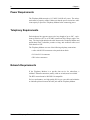
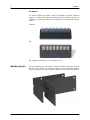
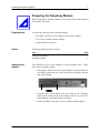
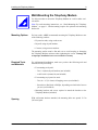
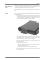
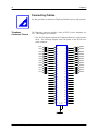
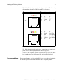
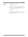
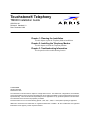
Touchstone® Telephony
TM608 Installation Guide
ARSVD01166
Release 6 Standard 1.0
Date: December 2008
Chapter 1: Planning the Installation
Use this chapter to plan the Telephony Modem installation.
Chapter 2: Installing the Telephony Modem
Use this chapter to install the Telephony Modem.
Chapter 3: Troubleshooting Information
This chapter describes troubleshooting features.
© 2008 ARRIS
All rights reserved
Printed in the USA
The information in this document is subject to change without notice. The statements, configurations, technical data,
and recommendations in this document are believed to be accurate and reliable, but are presented without express or
implied warranty. Users must take full responsibility for their applications of any products specified in this document.
The information in this document is proprietar y to ARRIS.
Protected under one or more of the following patents: 7,031,453; 7,100,011. Other patents pending or applied for.
ARRIS and Touchstone are trademarks or registered trademarks of ARRIS. All other trademarks and registered
trademarks are the property of their respective holders.
ii
Touchstone® Telephony Release 6 Standard 1.0 December 2008
Publication History
December 2008
Release 6 Standard 1.0 version of this document.
TM608 Installation Guide Release 6 Standard 1.0 December 2008
iv
Touchstone® Telephony Release 6 Standard 1.0 December 2008
Publication History
Contents
Safety Requirements ....................................................................... vii
Radio Frequency Emissions and Immunity ................................ ix
FCC Declaration of Conformity ............................................ ix
Product Safety ............................................................................ ix
CE Compliance ................................................................................. ix
Planning the Installation
1
Environmental Requirements ............................................................ 1
Site Location ...................................................................................... 1
Power Requirements ......................................................................... 2
Telephony Requirements ................................................................... 2
Network Requirements ...................................................................... 2
Telephony Modem Accessories ......................................................... 3
Telephony Adaptors .................................................................... 3
RJ-21X Adaptor .................................................................... 3
RJ-14/RJ-11 Adaptor ............................................................ 3
IDC Adaptor .......................................................................... 4
Wall-Mounting Kit ........................................................................ 4
Installing the Telephony Modem
5
Installation Over view ......................................................................... 5
Procedure: Inspecting and Unpacking the Telephony Modem ......... 6
Package Contents ....................................................................... 6
Procedure: Preparing the Telephony Modem ................................... 7
Requirements .............................................................................. 7
Attaching the Adaptor ................................................................. 7
Installing a Battery ...................................................................... 8
Procedure: Wall-Mounting the Telephony Modem ............................ 9
Mounting Options ........................................................................ 9
Required Tools and Materials ..................................................... 9
Spacing ....................................................................................... 9
Other Considerations .................................................................. 9
Procedure: Rack-Mounting the Telephony Modem ........................ 11
Required Tools .......................................................................... 11
Procedure: Connecting Cables ...................................................... 12
Telephone Connector Pinouts ................................................... 12
Recommendations .................................................................... 13
TM608 Installation Guide Release 6 Standard 1.0 December 2008
vi
Contents
Rear Panel Connectors ............................................................. 14
Subscriber Connections ............................................................ 14
Grounding Requirements .......................................................... 14
Tools .......................................................................................... 14
Troubleshooting Information
15
Front Panel LEDs ............................................................................ 15
Power-On Self Test Failure Pattern ........................................... 15
Foreign Voltage Pattern ............................................................ 15
Patterns: Normal Operation ...................................................... 17
Patterns: Star tup Sequence ...................................................... 17
MTA Star tup Sequence ...................................................... 18
CM Startup Sequence ........................................................ 18
Index
Touchstone® Telephony Release 6 Standard 1.0 December 2008
19
About this Document
This guide describes the installation and testing procedures for the Touchstone Multi-Line Telephony Modem models:
• TM608G/NA: North American DOCSIS, 115-240V AC power; 8 telephony lines with battery backup
• TM608G/CE: North Amercian DOCSIS, 115-240V AC power with
European power cord; 8 telephony lines with battery backup
Safety Requirements
ARRIS Telephony Modems comply with the applicable requirements for performance, construction, labeling, and information when used as outlined
below:
CAUTION
Risk of shock
Mains voltages inside this unit. No user serviceable parts inside. Refer service to qualified personnel only!
CAUTION
Risk of damage
Connecting the Telephony Modem to existing telephone wiring should be
performed only by a professional wiring technician.
The existing wires providing telephone service must be physically disconnected from the incumbent service provider’s network interface device. This
is a physical break in the connection, not just a discontinuation of service.
Failure to do so may result in damage to the Telephony Modem.
TM608 Installation Guide Release 6 Standard 1.0 December 2008
viii
About this Document
CAUTION
Risk of explosion
Replacing the battery with an incorrect type, heating a battery above 75°C, or
incinerating a battery, can cause product failure and a risk of fire or battery
explosion. Dispose of used batteries according to the instructions.
The battery used in this device may present a risk of fire or explosion when
heated above 75°C or incinerated. Dispose of used battery promptly. Keep
away from children. Do not dissemble or dispose of in fire.
Do not locate the equipment within 6 feet (1.9m) of a flame or ignition
source (e.g. heat registers, space heaters, fireplaces, etc.).
Do not use product near water (i.e. wet basement, bathtub, sink or near a
swimming pool, etc.), to avoid risk of electrocution.
Do not use the telephone to report a gas leak in the vicinity of the leak.
Avoid using and/or connecting the equipment during an electrical storm, to
avoid risk of electrocution.
Use only the power cord included with the equipment.
Clean the equipment using a dry cloth. Avoid solvents or other chemical
cleaners.
Equipment should be installed near the power outlet and should be easily
accessible.
The shield of the coaxial cable must be connected to earth (grounded) at the
entrance to the building in accordance with applicable national electrical
installation codes. In the U.S., this is required by NFPA 70 (National Electrical Code) Article 820. In the European Union and certain other countries,
CATV installation equipotential bonding requirements are specified in IEC
60728-11, Cable networks for television signals, sound signals and interactive services, Part 11: Safety. This equipment is intended to be installed in
accordance with the requirements of IEC 60728-11 for safe operation.
If the equipment is to be installed in an area serviced by an IT power line network, as is found in many areas of Norway, special attention should be given
that the installation is in accordance with IEC 60728-11, in particular Annex
B and Figure B.4.
In areas of high surge events or poor grounding situations and areas prone to
lightning strikes, additional surge protection may be required (i.e.
PF11VNT3 from American Power Conversion) on the AC, RF, Ethernet and
Phone lines.
When the Telephony Modem is connected to a local computer through an
Ethernet cable, the computer must be properly grounded to the building/residence AC ground network. All plug in cards within the computer must be
properly installed and grounded to the computer frame per the manufacturer’s specifications.
Touchstone® Telephony Release 6 Standard 1.0 December 2008
About this Document
Radio Frequency
Emissions and Immunity
ix
FCC Declaration of Conformity
This equipment has been tested and found to comply with the limits for a
Class B digital device, pursuant to part 15 of the FCC Rules. These limits
are designed to provide reasonable protection against harmful interference in
a residential installation. Operation is subject to the following two conditions: (1) this device may not cause harmful interference, and (2) this device
may accept any interference that may cause undesired operations.
This equipment generates, uses and can radiate radio frequency energy and,
if not installed and used in accordance with the instructions, may cause harmful interference to radio communications. However, there is no guarantee
that interference will not occur in a particular installation. If this equipment
does cause harmful interference to radio or television reception, which can be
determined by turning the equipment off and on, the user is encouraged to try
to correct the interference by one or more of the following measures:
• Reorient or relocate the receiving antenna.
• Increase the separation between the equipment and the receiver.
• Connect the equipment into an outlet on a circuit different from that to
which the receiver is connected.
• Consult the dealer or an experienced radio/TV technician for help.
The FCC advises that any unauthorized changes or modifications may void
the user’s authority to operate this equipment. For more information on FCC
conformity, please contact: ARRIS Group, 3871 Lakefield Drive, Suite 300,
Suwanee, GA 30024.
This product was FCC certified under test conditions that included the use of
the supplied cables between system components. To ensure compliance with
FCC regulation, the user must use these cables and install them properly.
Product Safety
UL listed per UL60950-1.
CE Compliance
This product complies with the provisions of the Electromagnetic Compatibility (EMC) Directive (89/336/EEC), the Amending Directive (92/31/EEC),
the Low Voltage Directive (73/23/EEC), and the CE Marking Directive
(93/68/EEC). As such, this product bears the CE marking in accordance with
the above applicable Directive(s).
A copy of the Declaration of Conformity may be obtained by contacting:
ARRIS Group, 3871 Lakefield Drive, Suite 300, Suwanee, GA 30024.
TM608 Installation Guide Release 6 Standard 1.0 December 2008
x
About this Document
As indicated by this symbol, disposal of this product
is governed by Directive 2002/96/EC of the European
Parliament and of the Council on waste electrical and
electronic equipment (WEEE). WEEE could potentially prove harmful to the environment; as such, upon
disposal of the Telephony Modem the Directive
requires that this product must not be disposed as
unsorted municipal waste, but rather collected separately and disposed of in accordance with local WEEE
ordinances.
This product complies with directive 2002/95/EC of
the European Parliament and of the Council of 27
January 2003 on the restriction of the use of certain
hazardous substances (RoHS) in electrical and electronic equipment.
Touchstone® Telephony Release 6 Standard 1.0 December 2008
1
Planning the
Installation
Use this chapter to plan the Telephony Modem installation.
Environmental Requirements
Provide at least 0.25 inch (6.4 mm) clearance on each side of the unit for
proper ventilation and cooling.
Mount the Telephony Modem properly to prevent uneven mechanical loading
on the chassis. Improper mounting can cause premature failure and potentially hazardous conditions.
When installed in a closed or multi-unit rack assembly, the operating temperature inside the rack environment may be higher than ambient temperature.
Install the Telephony Modem in an environment where the ambient temperatures remains below 50° Celsius.
Site Location
Note: Install the Telephony Modem in a restricted access location.
The Telephony Modem is designed to be installed in a wiring closet rack.
The wiring closet must provide access to power, telephony, and network
facilities as described in this chapter.
The Telephony Modem can be wall-mounted using the included wall-mounting brackets. ARRIS recommends wall-mounting to a plywood surface.
TM608 Installation Guide Release 6 Standard 1.0 December 2008
2
Chapter 1
Power Requirements
The Telephony Modem requires 115–240V, 50/60 Hz AC power. The socketoutlet must be properly earthed. Make sure that the power circuits have sufficient capacity to power the Telephony Modem before connecting power.
Telephony Requirements
Each telephone line supports copper wire loop lengths of up to 128Ω, equivalent to 1000 feet (457 m) of 26 AWG (American Wire Gauge) copper wire
loop. The loop length includes the cable between the Telephony Modem and
punch-down block, subscriber premises wiring, and extension cables used
with subscriber CPE.
The Telephony Modem uses one of the following telephony connections:
• cable with RJ-21X connectors to the punch-down block
• RJ-14 or RJ-11 connectors
• IDC rocker connectors
Network Requirements
If the Telephony Modem is to provide data service for subscribers, a
100BaseT Ethernet connection (usually a hub or switch) must be available.
The HFC network must be DOCSIS 2.0 compatible.
For best performance, use high-quality RG-6 type coax cable and minimize
or eliminate splitters between the cable jack and the Telephony Modem.
Touchstone® Telephony Release 6 Standard 1.0 December 2008
Planning the Installation
3
Telephony Modem Accessories
ARRIS provides optional accessories for the multi-line Telephony Modems.
Contact your ARRIS sales representative to order these items.
Telephony
Adaptors
The TM608 uses modular telephony adaptors (patent pending) to connect
telephone lines. The adaptors are field installable and replaceable. One of
the following adaptors is required to connect telephone lines to the Telephony
Modem. Choose the adapter best suited for the installation.
RJ-21X Adaptor
Use the RJ-21X adaptor, part number 728936, to connect the Telephony
Modem to a new or existing punch-down block.
RJ-14/RJ-11 Adaptor
Use the RJ-14/RJ-11 adaptor, part number 728934, or the RJ-11 adaptor, part
number 728935, to connect the Telephony Modem to standard telephone
cables. The RJ-14/RJ-11 adaptor provides RJ-14 connectors on odd-numbered lines for use with two-line phones.
TM608 Installation Guide Release 6 Standard 1.0 December 2008
4
Chapter 1
IDC Adaptor
Use an IDC adaptor, part number 728937 (TII adaptor) or 728942 (Channell
adaptor), to connect the Telephony Modem directly to telephone wiring. No
connectors or punch-down blocks are required for use with the IDC Rocker
adaptor.
Channell:
TII:
IDC adaptors do not require wire stripping or tools.
Wall-Mounting Kit
The wall-mounting kit, part number 729864, includes wall-mount brackets
and the screws required to attach the brackets to the Telephony Modem.
Screws required to secure the Telephony Modem to the rack are not included.
Touchstone® Telephony Release 6 Standard 1.0 December 2008
2
Installing the
Telephony Modem
Use this chapter to install the Telephony Modem.
CAUTION
Installation only by trained personnel
The TM608 is intended only for installation by wiring technicians and other
trained personnel.
Installation Overview
Perform the following procedures to install the TM608.
Procedure
Inspecting and Unpacking the Telephony Modem
Preparing the Telephony Modem
Wall-Mounting the Telephony Modem
Rack-Mounting the Telephony Modem
Connecting Cables
Page
6
7
9
11
12
Note: Tabletop usage is recommended only for lab trials rather than general
deployment.
TM608 Installation Guide Release 6 Standard 1.0 December 2008
6
Chapter 2
Inspecting and Unpacking the Telephony
Modem
Use this procedure to ensure the Telephony Modem package contains all the
required components, and that the unit is not damaged.
Package Contents
The TM608 package contains the following items:
1 Telephony Modem
2 Power cable
3 Three bar-coded MAC address labels
4 Wall-mounting brackets and screws
5 End-User License Agreement (EULA)
6 Battery (optional)
Note: If any items are missing, call your ARRIS sales representative for
replacements. If the contents appear to be damaged, file a claim with the
shipping company.
Action
Follow these steps to inspect and unpack the Telephony Modem.
1 Before opening the box, visually inspect the package for visible damage.
Note: If the package shows visible signs of damage, contact the shipping company for instructions. Do not open a damaged package
before consulting the shipping company.
2 If the package is undamaged, open the box at the top.
3 Lift the Telephony Modem bag out of the package.
4 If all the items are present and undamaged, affix the MAC address
stickers where they can be seen after installation.
Touchstone® Telephony Release 6 Standard 1.0 December 2008
Installing the Telephony Modem
7
Preparing the Telephony Modem
Before installing the Telephony Modem, use this procedure to install required
and optional accessories.
Requirements
You need the following items to attach an adaptor:
• RJ-14/RJ-11 adaptor, RJ-21X adaptor, or IDC Rocker adaptor
• Two screws (included with the adaptor)
• Small flat-blade screwdriver
Action
Perform the following tasks as needed.
Task
Page
Attaching the Adaptor
Installing a Battery
Attaching the
Adaptor
7
8
The TM608 uses one of three adaptors to attach telephone lines. Follow
these steps to attach the adaptor.
1 If an adaptor different from the required adaptor is already attached to
the TM608, remove the two screws and remove the adaptor from the
back of the TM608.
2 Align the pins on the adaptor with the sockets on the Telephony
Modem, and orient the label on the adapter with the top of the Telephony Modem, and push the adaptor into place.
3 Secure the adaptor using the two screws included with the adaptor.
TM608 Installation Guide Release 6 Standard 1.0 December 2008
8
Installing a Battery
Chapter 2
The TM608 has a battery bay in the front panel. You can install a battery in
the bay to provide power to the TM608 in case of a AC power outage. Follow these steps to install the backup battery.
1 Pull the battery door latch toward the center of the Telephony Modem
and remove the battery door. Set the battery door aside.
2 If necessary, remove the existing battery. Some batteries have a pull
strap as shown in the example below.
3 Insert the backup battery as shown below. Depending on the battery
capacity, the actual battery may differ from that shown.
4 Replace the battery door:
a Insert the battery door tab into the slot in the right side of the battery bay.
b Swing the battery door closed and press gently until it latches.
Touchstone® Telephony Release 6 Standard 1.0 December 2008
Installing the Telephony Modem
9
Wall-Mounting the Telephony Modem
Use this procedure to mount the Telephony Modem on a wall or other vertical surface.
Note: For rack-mounting instructions, see ‘‘Rack-Mounting the Telephony
Modem’’ on page 11. Rack-mounting requires the optional rack-mounting
bracket kit.
Mounting Options
For best results, ARRIS recommends mounting the Telephony Modem to one
of the following surfaces:
• Plywood or studs, using wood screws.
• Drywall, using drywall anchors.
• Concrete, using concrete anchors.
The mounting surface must be flat and even to avoid warping or damaging
the Telephony Modem enclosure when tightening the screws. Damage due
to improper installation is not covered under warranty.
Required Tools
and Materials
For wall-mounted installations, make sure you have the following tools and
materials before proceeding:
• For mounting on drywall:
– Two 1/4 (6mm) drywall anchors (not included)
– A drill with 1/4 (6mm) bit (not included)
• For mounting on plywood or studs:
– Two #6 x 1.5 (38.1 mm) self tapping screws (not included)
– Screwdriver (flat-blade or Phillips, depending on what kind of screws
you use) (not included)
• Mounting brackets and screws required to attach the brackets to the
Telephony Modem (included).
Spacing
With wall-mount brackets attached, the mounting holes are spaced 13.5 in
(343 mm) apart.
TM608 Installation Guide Release 6 Standard 1.0 December 2008
10
Other Considerations
Chapter 2
Make sure the intended mounting location has an AC receptacle (socket-outlet) nearby. The power cord must be able to reach the outlet without stretching or being run through openings in walls, ceilings, or floors.
Do not attach the power cord to the mounting surface or other building surfaces.
Action
Follow these steps to wall-mount the Telephony Modem using the provided
wall-mounting brackets.
1 Install one wall-mount bracket on each side of the Telephony Modem
so that the long flat side contacts the chassis and the brackets protrude
away from the bottom edge of the chassis, as shown below. Use four
screws to fasten each bracket to the Telephony Modem.
Note: Position the brackets so the bottom of the chassis will be against
the mounting surface. This position leaves the serial number label
exposed, and orients the front panel for best readability.
2 Make two marks, spaced horizontally, 13.5 inches (343 mm) apart, on
the mounting surface.
3 For drywall or concrete surfaces:
a Insert the mounting anchors into the wall, according to the directions provided with the anchors.
b Remove the mounting screws, leaving the anchors in place.
4 Lift the Telephony Modem into place on the wall and secure it using
the mounting screws.
Touchstone® Telephony Release 6 Standard 1.0 December 2008
Installing the Telephony Modem
11
Rack-Mounting the Telephony Modem
Use this procedure to mount the Telephony Modem in a 19-inch rack. For
wall-mounting, see ‘‘Wall-Mounting the Telephony Modem’’ on page 9.
Required Tools
To rack-mount the Telephony Modem, you need:
• #2 and #1 Phillips screwdrivers
• The optional rack-mounting bracket kit, part number 729864.
• Four screws to attach the unit to the rack.
Action
Follow these steps to rack-mount the Telephony Modem.
1 Install one rack mounting bracket on each side of the Telephony
Modem so that the smooth side contacts the enclosure and the brackets protrude away from the front edge of the unit as shown below.
Use four screws to fasten each bracket to the Telephony Modem.
2 Mount the Telephony Modem in the rack and secure it using two
screws on each side.
TM608 Installation Guide Release 6 Standard 1.0 December 2008
12
Chapter 2
Connecting Cables
Use this procedure to connect the Telephony Modem to power and networks.
Telephone
Connector Pinouts
The Telephone connector provides 8 lines of POTS (2-wire) telephone service. Three adaptors are available:
• The RJ-21X adaptor connects the Telephony Modem to a punch-down
block. The following diagram shows the pinout of the RJ-21X telephone connector.
1
RNG01
27
2
RNG02
TIP03
28
3
RNG03
TIP04
29
4
RNG04
TIP05
30
5
RNG05
TIP06
31
6
RNG06
TIP07
32
7
RNG07
TIP08
33
8
RNG08
TIP09
34
9
RNG09
TIP10
35
10
RNG10
TIP11
36
11
RNG11
TIP12
37
12
RNG12
38
13
39
14
40
15
41
16
42
17
43
18
44
19
45
20
46
21
47
22
48
23
49
24
50
25
Touchstone® Telephony Release 6 Standard 1.0 December 2008
G2
26
TIP02
G1
TIP01
Installing the Telephony Modem
13
• The RJ-14/RJ-11 adaptor provides 8 telephone jacks. The following
diagrams show the pinouts of RJ-14 and RJ-11 connectors.
Jack
Pin
Color
Signal
123456
1
2
3
4
5
6
n/c
n/c
Red
Green
n/c
n/c
n/c
n/c
Ring
Tip
n/c
n/c
123456
1
2
3
4
5
6
n/c
Black
Red
Green
Yellow
n/c
n/c
Line 2 Tip
Line 1 Ring
Line 1 Tip
Line 2 Ring
n/c
RJ-11:
RJ-14:
• The IDC adaptor provides rocker-style connections to connect telephone wires to the Telephony Modem without using tools.
To use the IDC adaptors, open the clip, insert the tip wire in the white
hole, and the ring wire in the orange hole, and snap the clip closed.
Recommendations
For best performance, use high-quality RG-6 type coax cable and minimize
or eliminate splitters between the cable jack and the Telephony Modem.
TM608 Installation Guide Release 6 Standard 1.0 December 2008
14
Rear Panel
Connectors
Chapter 2
Refer to the following photo for the locations of rear panel connectors when
performing this procedure.
1 Telephony adaptor jacks
2 Ethernet connector
3 Network RF (coax) connector
4 AC power connector
Subscriber
Connections
If the Telephony Modem is intended to provide data services, Ethernet lines
from subscriber units must be run to a switch or hub in the wiring closet.
The switch or hub must have at least one free connection for the Telephony
Modem.
Grounding
Requirements
The coax ground should be tied to AC building ground per NFPA 70
(National Electrical Code) Article 820 requirements.
Tools
A torque-limiting wrench can be used to secure RF cables.
Action
Follow these steps to connect cables to the Telephony Modem.
1 If a telephony adaptor is not already connected to the TM608, install
it as described in ‘‘Preparing the Telephony Modem’’ on page 7.
2 Connect the RF cable to the Network RF connector, and tighten to a
torque pressure of 17 to 23 Kg-cm (15 to 20 in-lb.).
Note: If a torque-limiting wrench is not available, tighten the connector by hand, then tighten a further 1/8 to 1/4 turn with a wrench.
3 (optional) Connect a 100BaseT Ethernet cable between the Telephony
Modem Ethernet jack and the Uplink port on a hub or switch.
4 Connect the power cord between the AC connector on the Telephony
Modem and the AC power source.
5 Connect telephony cables as appropriate for the installed adaptor.
Touchstone® Telephony Release 6 Standard 1.0 December 2008
3
Troubleshooting
Information
This chapter describes troubleshooting features.
Front Panel LEDs
The front panel LEDs provide information about DOCSIS and telephony status.
The LED patterns shown in this section are valid for the default firmware version installed on the Telephony Modem. See the Troubleshooting Guide corresponding to the actual firmware installed for updated LED patterns.
Power-On Self
Test Failure Pattern
When a Telephony Modem fails power-on self test (POST), it repeats the following sequence:
• POWER LED on for 2 seconds; other LEDs off
• All LEDs flash rapidly (10 times per second) for 10 seconds
A Telephony Modem repeatedly displaying this sequence is defective and
should be replaced.
TM608 Installation Guide Release 6 Standard 1.0 December 2008
16
Foreign Voltage
Pattern
Chapter 3
If the Telephony Modem detects a foreign voltage on one or more telephone
lines, it repeats the following sequence:
• All LEDs on
• The LED corresponding to the telephony line(s) with foreign voltage
If you see this sequence, immediately disconnect the affected lines and eliminate the voltage source. Common sources of foreign voltage include:
• connection to incumbent telephone service
• shorted wires
• defective CPE
Note: All telephony lines must be physically disconnected from incumbent
service before connecting the lines to the Telephony Modem. Cancellation of
incumbent service is not sufficient.
Touchstone® Telephony Release 6 Standard 1.0 December 2008
Troubleshooting Information
Patterns: Normal
Operation
Operating
Mode
AC Power
Good
Power
On
17
The following table shows LED patterns for the Telephony Modem during
normal operation.
DS
US
On =
Online
On =
Online
Flash =
Off-line
Flash =
Off-line
Online
Link
On =
network
available
On = CPE
connected
Tel. 1 – 8
On =
On-hook
Flash =
Off-hook
Off = CPE
disconnected
Off =
network
not
available
Flash = CPE
activity1
Slow Flash2 =
Line card
error
Off =
disabled
On =
On-hook
Flash =
Off-hook
AC Power
Fail
Flash
Off
Off
Off
Off
Slow Flash =
Line card
error
Off =
disabled
Firmware
Upgrade
Line Card
Protection
State4
x3
Flash
Flash
On
x
x
Flash
Flash
Flash
Flash
Flash
Flash
Off
Off
Off
Off
Off
(line)
1. This state is valid only if the Telephony Modem is online.
2. Slow Flash is 1 flash per second.
3. An x indicates the LED state reflects the ‘‘AC Power Good’’ or ‘‘AC Power Fail’’ status.
4. Line Card Protection indicates foreign voltage present on one or more lines. In this state,
the LED pattern alternates between all LEDs flashing and only the Telephony LEDs corresponding to the line or lines where the fault was detected.
TM608 Installation Guide Release 6 Standard 1.0 December 2008
18
Patterns: Startup
Sequence
Chapter 3
The following tables show LED patterns for the Telephony Modem during
each phase of the startup sequence.
MTA Startup Sequence
If the MTA fails to complete registration, note the LED pattern and call your
next level of support.
Step
0
1
2-4
5
6
7
Description
Power,
DS, US,
Online
No Power
Off
Self-Test
Flash
CM Initialization; see
‘‘CM Startup Sequence’’ below.
Telephony DHCP
On
Telephony SNMP/TFTP
On
Telephony RSIP
On
Link
Telephone
Off
Flash
Off
Flash
Off
Off
On
On
On
Flash
Off
Flash
MTA Normal Operation
CM Startup Sequence
If the modem fails to complete registration, note the LED pattern and call
your cable operator for assistance.
Step
Description
DS
US
Online
Link
2
3
4
Downstream scan/sync
Upstream ranging
DOCSIS DHCP/TFTP
Flash
On
On
Off
Flash
On
Off
Off
Flash
Off
Off
Off
CM Normal Operation
Touchstone® Telephony Release 6 Standard 1.0 December 2008
4
Index
L
A
AC power 2
connecting 14
accessories 3
adaptor, attaching 7
attaching the adaptor 7
B
battery, installing 8
bracket, rackmount 10–11
C
cable torque, RF 14
CM startup sequence, LED patterns 18
connecting AC power 14
connection
Ethernet 2
RF 2
connector, pinouts, telephone 12
connectors, rear panel 14
considerations, data service 14
contents, package 6
D
damage, in case of 6
data service considerations 14
E
environmental requirements 1
Ethernet connection 2
F
foreign voltage pattern 16
front panel LEDs 15
G
grounding requirements 14
I
in case of damage 6
inspection, unpacking and 6
installing a battery 8
LED patterns
CM startup sequence 18
MTA startup sequence 18
normal operation 17
LEDs, front panel 15
length, maximum loop 2
location, site 1
loop length, maximum 2
M
maximum loop length 2
mounting
rack 11
tabletop 5
wall 9
MTA startup sequence, LED patterns 18
N
network requirements 2
normal operation, LED patterns 17
P
package contents 6
panel
connectors, rear 14
LEDs, front 15
pattern, foreign voltage 16
patterns
CM startup sequence, LED 18
MTA startup sequence, LED 18
normal operation, LED 17
pinouts
RJ-21X 12
telephone connector 12
power
AC 2
connecting AC 14
requirements 2
power-on self test 15
R
rack mounting 11
rackmount bracket 10–11
rear panel connectors 14
requirements
environmental 1
grounding 14
network 2
TM608 Installation Guide Release 6 Standard 1.0 December 2008
20
Chapter 4
power 2
telephony 2
RF
cable torque 14
connection 2
RJ-21X, pinouts 12
S
self test, power-on 15
service considerations, data 14
site location 1
startup
LED patterns, CM 18
LED patterns, MTA 18
T
tabletop mounting 5
telephone connector, pinouts 12
telephony requirements 2
torque, RF cable 14
troubleshooting 15
U
unpacking and inspection 6
V
voltage pattern, foreign 16
W
wall mounting 9
Touchstone® Telephony Release 6 Standard 1.0 December 2008
Touchstone® Telephony
TM608 Installation Guide
© 2008 ARRIS
All rights reserved
Printed in the USA
The information in this document is subject to change without
notice. The statements, configurations, technical data, and
recommendations in this document are believed to be accurate
and reliable, but are presented without express or implied
warranty. Users must take full responsibility for their applications
of any products specified in this document. The information in
this document is proprietar y to ARRIS.
Protected under one or more of the following patents: 7,031,453;
7,100,011. Other patents pending or applied for.
ARRIS and Touchstone are trademarks or registered trademarks
of ARRIS. All other trademarks and registered trademarks are
the property of their respective holders.