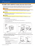
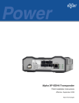
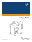
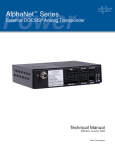
1
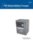
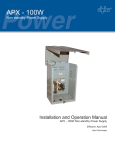
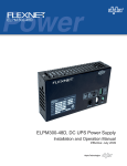
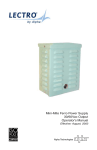
DCX3000 Portable Generator
Operation Manual
3.0kW, 36/48V, DC Portable Generator
Effective: September 2006
Alpha Technologies
Power
Alpha Technologies
®
AlphaGen DCX3000
3.0kW, 36/48V DC Portable Generator
Operation Manual
041-028-B0-003, Rev. C
Effective Date: September 2006
Copyright© 2006
Alpha Technologies, Inc.
member of The
GroupTM
NOTE:
Photographs contained in this manual are for illustrative purposes only. These photographs may not match
your installation.
NOTE:
Operator is cautioned to review the drawings and illustrations contained in this manual before proceeding. If
there are questions regarding the safe operation of this powering system, please contact Alpha Technologies
or your nearest Alpha representative.
NOTE:
Alpha shall not be held liable for any damage or injury involving its enclosures, power supplies, generators,
batteries, or other hardware if used or operated in any manner or subject to any condition not consistent with
its intended purpose, or is installed or operated in an unapproved manner, or improperly maintained.
Contacting Alpha Technologies: www.alpha.com
or
For general product information and customer service (7 AM to 5 PM, Pacific Time), call
1-800-863-3930
For complete technical support, call
1-800-863-3364
7 AM to 5 PM, Pacific Time or 24/7 emergency support
3
Table of Contents
Safety Notes .......................................................................................................................... 6
1.0
Introduction ................................................................................................................. 8
2.0
Specifications.............................................................................................................. 9
3.0
Battery Cable Connections ....................................................................................... 10
Enclosures with Generator Access Door ....................................................... 10
3.2
Enclosures without Generator Access Door ...................................................11
3.3
Grounding ...................................................................................................... 16
4.0
Starting the Engine ................................................................................................... 18
5.0
Engine Shut-Down and Cable Removal ................................................................... 20
6.0
4
3.1
5.1
Long-term Storage ......................................................................................... 20
5.2
Scheduled Maintenance ................................................................................ 20
5.3
Transporting the Generator ............................................................................ 20
5.4
Fuse Replacement ......................................................................................... 21
Maintenance Record................................................................................................. 22
041-028-B0-003, Rev. C
List of Figures
Fig. 1-1, DCX3000 Overview ................................................................................................. 8
Fig. 1-2, Basic Block Diagram ............................................................................................... 8
Fig. 3-1, Generator Access Door and Battery Pack Adapter Cable ..................................... 10
Fig. 3-2, Enclosure without Generator Access Door.............................................................11
Fig. 3-3, Alligator Clamp-style Connection .......................................................................... 12
Fig. 3-4, Ring Lug-style Connection .................................................................................... 13
Fig. 3-5, Novus-style Connection ........................................................................................ 14
Fig. 3-6, Y-style Connection................................................................................................ 15
Fig. 3-7, Generator Grounding ............................................................................................ 16
Fig. 3-8, Overview of PWE Installation ................................................................................ 17
Fig. 4-1, Starting the Engine ................................................................................................ 18
Table 4-1, Battery Voltage and Output Indications .............................................................. 19
041-028-B0-003, Rev. C
5
Safety Notes
Review the drawings and illustrations contained in this manual before proceeding. If there are any questions
regarding the safe installation or operation of this product, contact Alpha Technologies or the nearest Alpha
representative. Save this document for future reference.
To reduce the risk of injury or death, and to ensure the continued safe operation of this product, the following
symbols have been placed throughout this manual. Where these symbols appear, use extra care and
attention.
ATTENTION:
The use of ATTENTION indicates specific regulatory/code requirements that may affect the placement of
equipment and /or installation procedures.
NOTE:
A NOTE provide additional information to help complete a specific task or procedure.
CAUTION!
The use of CAUTION indicates safety information intended to PREVENT DAMAGE to material or
equipment.
WARNING!
WARNING presents safety information to PREVENT INJURY OR DEATH to the technician
or user.
6
041-028-B0-003, Rev. C
General Safety Information
•
The manufacturer cannot anticipate every circumstance that may involve a hazard, therefore, these
warnings are not all inclusive.
•
Do not use the generator or any of its parts as a step.
•
Generator must be properly grounded.
•
Do not place or operate the generator in standing water, or expose to a forced spray of water.
•
Do not make or break any connections while generator is running.
•
Fuel spillage cleanup is the responsibility of the operator and should comply with local codes and
regulations.
•
Do not refuel the generator while engine is running. Allow generator to cool before refueling.
•
For fire safety, the generator must be properly connected, maintained, and in compliance with applicable
codes and regulations.
•
Engine exhaust contains carbon monoxide gas, which can be deadly in closed or poorly ventilated areas.
•
Prior to each use, inspect the generator for leaks and damage. Immediately repair or replace any
damaged parts.
•
Never operate the generator near combustible materials.
•
Ensure cables do not cross hot surfaces or sharp edges. Inspect cables before and after each use.
•
Drain oil and empty the fuel tank before transporting. Fuel can leak from the filler cap if the generator is
tilted.
•
Never refuel the generator in the vicinity of open flames of heat sources. Do not smoke near the
generator.
•
The generator should be operated on level ground. If necessary, it may be operated on a grade <15°.
•
Use only vendor-authorized repair parts.
•
Do not operate generator unattended.
ATTENTION:
•
Alpha Technologies’ products are subject to change through continual improvement processes. Therefore,
specifications and design layouts may vary slightly from descriptions included in this manual. Updates to
the manual are issued when changes affect form, fit or function.
•
This product is manufactured to conform to the Federal Communications Commissions (FCC) Part 15,
Class A regulations. It is intended to be used for commercial, industrial or business environments.
•
This device complies with part 15 of the FCC rules. Operation is subject to the following two conditions:
(1) This device may not cause harmful interference, and (2) this device must accept any interference
received, including interference that may cause undesired operation.
041-028-B0-003, Rev. C
7
1.0 Introduction
The Alphagen DCX3000 portable DC generator supplies DC power to a power node battery bus
during AC line interruptions. Upon loss of commercial AC power, the existing battery strings supply
the power supply inverters. After some interval of battery discharge, the operator deploys the portable
generator at the site to supply power to the DC bus. The generator delivers continuous, high-quality
power throughout the commercial AC interruption period. After restoration of commercial AC power,
the operator disconnects and removes the generator.
9
1 Status LEDs
2 Engine Switch
3 Choke
1
5
8
4 Fuel Valve
2
5 Voltmeter
6 Output Off Button
7
3
4
6
7 DC Out
8 Pull-start
9 Fuel Tank
Fig. 1-1, DCX3000 Overview
Engine
Alternator
Rectifier
Load
(batteries)
DC Sense Feedback
Controller
Fig. 1-2, Basic Block Diagram
8
041-028-B0-003, Rev. C
2.0 Specifications
Engine
Honda GX 200 6.5 hp, air-cooled, OHV, single cylinder, manual recoil starting, manual choke
Fuel/Fuel Tank
Unleaded gasoline/3.5 gallon metal tank with level gauge
Rated Power
2800W continuous, 3000W maximum
Alternator
Permanent magnet, brushless, bearingless
Output Voltage
Dual range selector
36V: 39.5VDC, nominal at generator output connector
48V: 52.5VDC, nominal at generator output connector
Output Regulation
+/-1VDC
Control Features
Automatic Voltage Regulation
Electronic Governor
Overcurrent Protection
Analog voltmeter with back light
Cable Interface
Anderson type SBE-80 connector
Runtime
@25% load (48V): 15.4 hours
@25% load (36V): 17.5 hours
@100% rated load: 6.5 hours
Audible Noise
Approximately 65dBA @ 7 meters under full load
Frame
Fully enclosed
Dry Weight
117 lb
Dimensions
22" H X 17.6" W X 25.9" D (557mm x 447mm x 657mm)
Operating Temp
5°F to 104°F (-15°C to 40°C)
Required Accessories
Output Interface Cable: Available in 10', 30', or 50' lengths
Battery Interface Cable: Choose Ring Lug, Heavy-duty Alligator Clamp, or Y-adapter (Connects the
power supply’s battery input directly to the generator. See Section 3.0 for more
information)
Agency Compliance
CSA 22.2 No. 100-95
FCC part 15B Class A
CARB
UL 50, Section 30
NFPA 37, 70
EPA
Optional Accessories
Portable Generator Wheel Kit: P/N 745-793-20
Punch Tool Kit for Enclosures, 2.5" dia: P/N 745-131-20
Enclosure Upgrade Kit: P/N 745-131-21
Cable Bag and Cable Key Lanyard: P/N 745-764-21
Locking Handle: P/N 745-792-20
NOTE:
Please refer to www.alpha.com for available options and data sheets.
041-028-B0-003, Rev. C
9
3.0 Battery Cable Connections
3.1
Enclosures with Generator Access Door
Tools and Materials Needed:
•
Portable Generator Battery Cable Kit
•
DC Multimeter
Procedure:
1. Open the enclosure’s battery compartment and locate the battery pack connections for
the positive and negative battery cables leading to the power supply.
2. Observing polarity (red to positive, black to negative), connect the Battery Pack
Adapter Cable to the connections located in Step 1. Attach Ring Lug or Alligator Clamp
connections directly to the battery post. See Fig. 3-5 and Fig. 3-6 for Novus-style and Ystyle connections. Do not connect the extension cable to the DC OUT jack on the
front panel of the generator at this time.
3. Route the extension cable (10’, 30’, or 50’) into the enclosure’s battery compartment.
Protect cable from chafing against sharp edges.
4. Connect the Battery Pack Adapter Cable to the extension cable. Extension cables are
equipped with in-line fuses. Replace only with 100 Amp 300VAC fuse (Alpha P/N 460191-10).
CAUTION!
Inspect cable sets before each use for damage and wear. Use only cable sets that are designed for
this generator.
Fig. 3-1, Generator Access Door and Battery Pack Adapter Cable
10
041-028-B0-003, Rev. C
3.0
Battery Cable Connections, continued
3.2
Enclosures without Generator Access Door
Tools and Materials Needed:
•
2.5" Punch Tool Kit for Enclosures (Alpha P/N 745-131-20)
•
2.5" Enclosure Upgrade Kit (Alpha P/N 745-131-21)
•
Electric drill
•
#7 Drill bit (.2010”) or #9 drill bit (.1960”)
•
#2 Phillips screwdriver
WARNING!
Disconnect all sources of service power to the enclosure before drilling holes. Ensure the
area is clear of wires and electrical boxes. Do not locate the hole above electrical boxes to
prevent damage from water intrusion while the plug is removed.
Procedure:
1. If not previously installed, punch or cut a 2.5” hole in the enclosure (shown below) to
route the generator’s battery cable. Ensure area is clear of electrical wires and boxes.
2. Install the grommet into the hole, and install the weatherproof plug into the grommet.
3. Using the #7 or #9 drill bit, drill a hole approximately 2” below and to one side of the
grommet, attach the lanyard on the inside of the enclosure with the #10 bolt and nut
provided.
Suggested location of battery
cable hole for PWE enclosures
Hole for lanyard bolt
Fig. 3-2, Enclosure without Generator Access Door
041-028-B0-003, Rev. C
11
3.0
Battery Cable Connections, continued
3
Extension Cable Set,
50’ P/N 875-324-21
30’ P/N 875-324-20
10’ P/N 875-324-22
Red
2
Fuse
1
Alligator Clamp-style
Battery Pack Adapter Cable,
P/N 874-946-20
Black
Ensure clamps lay flat against
batteries, facing inward
Fig. 3-3, Alligator Clamp-style Connection
12
041-028-B0-003, Rev. C
3.0
Battery Cable Connections, continued
Extension Cable Set,
50’ P/N 875-324-21
30’ P/N 875-324-20
10’ P/N 875-324-22
3
Red
2
Fuse
Ring Lug-style
Battery Pack Adapter Cable,
P/N 874-946-21
1
Black
Cable rings connect directly
to the battery terminals
Fig. 3-4, Ring Lug-style Connection
041-028-B0-003, Rev. C
13
3.0
Battery Cable Connections, continued
Circuit Breaker
must be CLOSED
OUTPUTS
GENERATOR
BREAKER
CONVENIENCE
FROM XT1
UPS
BYPAS
S
EXT GENERATOR
LA-P
Plus
60A
HEATING PADS
Novus Power
Panel
BLACK
RED
Novus-style
Battery Pack Adapter Cable
P/N 875-324-23
Extension Cable Set,
50’ P/N 875-324-21
30’ P/N 875-324-20
10’ P/N 875-324-22
Fig. 3-5, Novus-style Connection
14
041-028-B0-003, Rev. C
3.0
Battery Cable Connections, continued
Y-style
Battery Pack Adapter Cable
P/N 874-946-22
Extension Cable Set,
50’ P/N 875-324-21
30’ P/N 875-324-20
10’ P/N 875-324-22
3
2
Fuse
1
Fig. 3-6, Y-style Connection
041-028-B0-003, Rev. C
15
3.0
Battery Cable Connections, continued
3.3
Grounding
Tools and Materials Needed:
#8AWG copper ground wire and clamps
Procedure:
1. Read and thoroughly understand the Engine Owner’s Manual before operating this
equipment.
2. Before starting the generator, follow all instructions outlined in the BEFORE OPERATION
section of the Engine Owner’s Manual.
3. Attach #8AWG copper grounding wire between the generator grounding lug and the
service entrance grounding bar, or directly to the utility grounding rod.
WARNING!
To prevent injury, the generator must share a common ground with the enclosure service
entrance.
Generator Grounding Lug
Fig. 3-7, Generator Grounding
16
041-028-B0-003, Rev. C
3.0
Battery Cable Connections, continued
Ground Wire
To prevent injury, the generator MUST share a common ground with the enclosure service
entrance.
Power Meter
Ground Stake
Ground Wire
Fig. 3-8, Overview of PWE Installation
041-028-B0-003, Rev. C
17
4.0 Starting the Engine
Prior to starting the generator, review the Safety Information on page 6 of this manual.
Set the generator on a flat, level surface, free of standing or running water, or combustible materials.
Operating the generator at an angle of more than 15 degrees may result in the oil level dropping
below a safe level. This may cause the low oil sensor to trip, or failure of the generator to shut down.
This generator runs very quietly. It is not always possible in ambient-noise situations to determine
whether it is running simply by sound. Verify that the generator is OFF before proceeding with the
following procedure.
Tools and Materials Needed:
#2 Flat-tip screwdriver (to open side panel)
Procedure:
1. Verify fuel is in the fuel tank.
2. Open the maintenance cover on the left side panel of the generator.
Set the Voltage Select switch to match the battery pack voltage (36V or
48V). Close cover before starting engine.
Voltage Select Switch
3. Verify polarity and battery voltage continuity on extension cables.
Connect the extension cable coupler to the DC OUT jack on the
generator. Verify the voltmeter indicates the voltage of the battery pack.
NOTE:
Set correct voltage on Voltage Select Switch. Generator will not engage with incorrect voltage
setting.
4.
5.
6.
7.
Insert key and turn the ENGINE SW to the ON position.
If the engine is cold, pull the CHOKE knob out.
Turn the FUEL VALVE to the ON position.
Pull the starter handle (right side panel) until the engine starts. Verify the OUTPUT INDICATOR
LED is a steady green (not blinking). If the OUTPUT INDICATOR LED is flashing red, a voltage
mis-match has occurred, or the battery pack is excessively discharged. Refer to the voltage table
on page 19 for more information.
8. As the engine warms, push the CHOKE knob in.
OUTPUT INDICATOR LED
(Step 7)
DC OUT
(Step 3)
ENGINE SW
(Step 4)
FUEL VALVE
(Step 6)
CHOKE
(Steps 5, 8)
Fig. 4-1, Starting the Engine
18
041-028-B0-003, Rev. C
4.0
Starting the Engine, continued
Battery Voltage 1
0V to 2V
2V to 27V
27V to 42V
42V to 55V
>56V
Voltage Select Output Indicator
(Green LED)
Switch Position
Overload Alarm
(Red LED)
Forced Output 2
36V
OFF
OFF
Not Available
48V
OFF
OFF
36V
OFF
Not Available
ENABLED
48V
OFF
FLASHING
FLASHING
36V
48V
ON
OFF
FLASHING
36V
OFF
48V
ON
36V
OFF
OFF
48V
OFF
ENABLED
Not Available
ENABLED
FLASHING
Not Available
Not Available
Not Available 3
FLASHING
Not Available 3
FLASHING
OFF
1
All battery voltage measurements are ± 1V
2
To enable forced output when the Overload Alarm LED is flashing, press the output button for at least 5
seconds. The Overload Alarm LED stops flashing. Release the output button, and then press it again for
at least five seconds. The Output Indicator LED turns on steady, and power output begins. The operator
may then release the output button.
3
Engine shuts down after 1 second.
Table 4-1, Battery Voltage and Output Indications
NOTE:
To manually disconnect the Output Voltage, press the OUTPUT SW momentarily to remove voltage from the
battery pack. See Step 1 of Section 5.0, Engine Shutdown and Cable Removal.
To re-establish output voltage after manual or automatic disconnection, turn the ENGINE SW counterclockwise to OFF. After the engine stops, turn the ENGINE SW to ON and follow the procedures in Section
4.0, Starting the Engine.
041-028-B0-003, Rev. C
19
5.0 Engine Shut-Down and Cable Removal
WARNING!
Engine block and muffler become extremely hot during normal operation.
Procedure:
1. Press the OUTPUT SW to remove voltage from the battery pack.
2. Turn the ENGINE SW OFF.
3. Turn the FUEL VALVE OFF.
4
Disconnect the battery pack adaptor from the extension cable.
5. Remove the extension cable from the front panel of the generator.
6. Remove the battery pack adaptor from the battery pack.
7. Remove #8AWG copper ground wire.
5.1
Long-term Storage
If the generator is not going to be operated for an extended period of time, follow the storage
instructions in the TRANSPORTING/STORAGE section of the Engine Owner’s Manual.
CAUTION!
Drain fuel system before extended storage. Inspect fuel system and cable sets prior to restarting
generator after extended storage.
5.2
Scheduled Maintenance
Refer to the Honda Engine Owner’s Manual and follow all instructions in the MAINTENANCE
section.
5.3
Transporting the Generator
Refer to the Engine Owner’s Manual and follow all instructions in the TRANSPORTING/
STORAGE section.
20
041-028-B0-003, Rev. C
5.0
Engine Shut-Down and Cable Removal, continued
5.4
Fuse Replacement
Tools and Materials Needed:
•
10mm and 8mm socket
•
Ratchet handle
•
Torque wrench
•
Replacement fuse: Alpha P/N 460-273-10, Hinode Electric Co. P/N 350GH-80
Procedure:
1. Set the ENGINE SW to OFF. Disconnect the extension
cable from the DC Out jack.
2. Remove the four 10mm nuts from the front plastic housing,
and remove the housing.
3. Locate the fuse cover below the OUTPUT SW.
4. Remove the two 8mm bolts on the bottom of the fuse cover.
Remove the cover.
5. Remove the two 10mm nuts holding the fuse onto the fuse
holder. When reassembling, carefully tighten nuts to the
following torque specifications:
3.2 to 6.4 N m
2.4 to 4.7 ft-lbs.
28 to 56 in-lbs.
6. Replace fuse, and reassemble the generator in reverse
order.
041-028-B0-003, Rev. C
21
6.0 Maintenance Record
Use the following form to log maintenance and repair of your DCX3000.
Maintenance Record (Refer to engine owners manual for service requirements and intervals)
Model Number
Date
22
Hour
Meter
Serial Number
Action
Initials
041-028-B0-003, Rev. C
Power
Alpha Technologies
®
Alpha Technologies
3767 Alpha Way
Bellingham, WA 98226
USA
Tel: +1 360 647 2360
Fax: +1 360 671 4936
Web: www.alpha.com
Alpha Technologies Ltd.
4084 McConnell Court
Burnaby, BC, V5A 3N7
CANADA
Tel: +1 604 430 1476
Fax: +1 604 430 8908
Alpha Technologies
Europe Ltd.
Twyford House
Thorley
Bishop's Stortford
Hertfordshire
CM22 7PA
UNITED KINGDOM
Tel: +44 01279 501110
Fax: +44 01279 659870
Alpha Technologies GmbH
Hansastrasse 8
D 91126 Schwabach
GERMANY
Tel: +49 9122 79889 0
Fax: +49 9122 79889 21
Alphatec, Ltd
P.O. Box 56468
Limassol, Cyprus
CYPRUS
Tel: +357 25 375675
Fax: +357 25 359595
AlphaTEK ooo
Khokhlovskiy Pereulok 16
Stroenie 1
109028 Moscow
RUSSIA
Tel: +7 495 916 1854
Fax: +7 495 916 1349
Alphatec Baltics
S. Konarskio G. 49
Vilnius 2009
LITHUANIA
Tel: +350 5 210 5291
Fax: +350 5 210 5292
Alpha Technologies
5 Avenue Victor Hugo
F 92140 Clamart France
FRANCE
Tel: +33 1 41 90 07 07
Fax: +33 1 41 90 93 12
Due to continuing product improvements, Alpha reserves the right to change specifications without notice.
Copyright © 2006 Alpha Technologies, Inc. All rights reserved. Alpha is a registered trademark of Alpha Technologies. 041-028-B0-003, Rev. C.