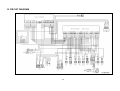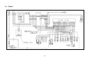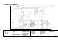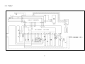
1
SERVICE MANUAL DISHWASHER ELECTROLUX HOME PRODUCTS ITALY S.p.A. Spares Operations Italy Corso Lino Zanussi, 30 I - 33080 PORCIA /PN (ITALY) Fax +39 0434 394096 Publication number 599 37 31-44 EN Dishwasher with electronic control EDW 2503-LCD & “Talkie” (Functionality) “DIVA” 60cm “DIVA BIG” 60cm “totally integrated” 911 938 … 911 988… Edition: 2005-10 Production: ZM - Solaro (IT) SOI/TD-PR 1 2 CONTENTS 1 2 3 4 5 6 7 PRECAUTIONS ...................................................................................................................................... 5 GENERAL CHARACTERISTICS............................................................................................................ 5 CONTROL PANEL.................................................................................................................................. 6 3.1 LCD ................................................................................................................................................. 6 3.2 Controls ........................................................................................................................................... 7 3.2.1 Turning the appliance on and off (S0) .......................................................................................... 7 3.2.2 Selecting programmes.................................................................................................................. 7 3.2.3 Selecting options .......................................................................................................................... 7 3.2.4 Reset ............................................................................................................................................ 7 3.3 “Talkie” Version ............................................................................................................................... 8 3.3.1 Vocal messages ........................................................................................................................... 9 WASHING ............................................................................................................................................. 12 4.1 Wash programmes........................................................................................................................ 12 4.1.1 Automatic programme ................................................................................................................ 12 4.2 Selecting a programme ................................................................................................................. 13 4.2.1 Cancelling a programme ............................................................................................................ 14 4.2.2 Interrupting a programme ........................................................................................................... 14 4.3 Options .......................................................................................................................................... 15 4.3.1 Eco-drying: ................................................................................................................................. 15 4.3.2 Extra rinse: ................................................................................................................................. 15 4.3.3 Detergent.................................................................................................................................... 15 4.3.4 Rinse-aid:.................................................................................................................................... 15 4.3.5 Water hardness: ......................................................................................................................... 15 4.3.6 Language:................................................................................................................................... 15 4.3.7 Buzzer volume:........................................................................................................................... 16 4.3.8 Brightness of LCD: ..................................................................................................................... 16 4.3.9 Contrast of LCD:......................................................................................................................... 16 4.3.10 Delayed start: ............................................................................................................................. 16 4.4 Sequence of operations ................................................................................................................ 17 BUILD CHARACTERISTICS ................................................................................................................ 18 5.1 Structure........................................................................................................................................ 18 5.2 Hydraulic circuit............................................................................................................................. 19 ELECTRICAL COMPONENTS AND FUNCTIONS .............................................................................. 20 6.1 EDW2503 Electronic control system............................................................................................. 20 6.1.1 Functions performed by the mother board ................................................................................. 20 6.1.2 Memories contained in the electronic control system ................................................................ 20 6.1.3 Power failures............................................................................................................................. 21 6.2 Electrical specifications ................................................................................................................. 21 6.2.1 Components ............................................................................................................................... 21 6.2.2 Sensors....................................................................................................................................... 21 6.3 Power feed and selection of programmes .................................................................................... 22 Water filling ........................................................................................................................................... 22 7.1 Fill circuit ....................................................................................................................................... 22 7.1.1 Pressure switches on fill level and anti-overflow system ........................................................... 22 7.1.2 Fill system................................................................................................................................... 22 7.1.3 Anti-flooding device .................................................................................................................... 22 7.1.4 Anti-overflow system .................................................................................................................. 22 7.2 Control of water filling.................................................................................................................... 22 7.2.1 Static filling ................................................................................................................................. 23 7.2.2 Dynamic filling ............................................................................................................................ 23 7.2.3 Level control during washing ...................................................................................................... 23 7.3 Water filling time............................................................................................................................ 23 7.3.1 Static filling time.......................................................................................................................... 23 7.3.2 Dynamic filling time..................................................................................................................... 23 7.3.3 Interruption of water filling .......................................................................................................... 23 7.4 Washing system............................................................................................................................ 24 7.5 Level control during washing......................................................................................................... 24 7.5.1 Control of wash pump................................................................................................................. 24 7.6 Heating .......................................................................................................................................... 24 7.7 Built-in detergent dispenser .......................................................................................................... 25 7.8 Draining ......................................................................................................................................... 25 7.8.1 “Siphon” effect ............................................................................................................................ 25 3 Regeneration system .................................................................................................................... 26 7.9 7.10 Resin washing ............................................................................................................................... 26 7.11 Regeneration levels ...................................................................................................................... 26 7.11.1 “Blending” function...................................................................................................................... 27 8 DRYING ................................................................................................................................................ 27 8.1 “Turbo-dry” drying ......................................................................................................................... 27 9 SERVICE .............................................................................................................................................. 28 9.1 Accessing the diagnostic mode .................................................................................................... 28 9.2 Displaying alarms and activating individual components.............................................................. 29 9.2.1 Table of alarm codes .................................................................................................................. 30 9.3 Cancelling alarms from memory ................................................................................................... 32 9.4 Test cycle ...................................................................................................................................... 32 9.5 Disabling / enabling pulse washing............................................................................................... 32 9.6 Enabling / disabling an extra rinse ................................................................................................ 33 9.7 Brightness ..................................................................................................................................... 33 9.8 Setting the water hardness ........................................................................................................... 33 10 CIRCUIT DIAGRAM.............................................................................................................................. 34 10.1 “Talkie” .......................................................................................................................................... 35 11 BASIC CIRCUIT DIAGRAM.................................................................................................................. 36 11.1 “Talkie” .......................................................................................................................................... 37 11.2 Checking components for proper operation.................................................................................. 38 12 QUICK GUIDE ...................................................................................................................................... 39 13 TABLE OF PROGRAMMES ................................................................................................................. 41 4 Purpose of this manual The purpose of this manual is to provide service personnel (who have the basic knowledge necessary for repairing dishwashers) with information on dishwashers equipped with the EDW2503 electronic control system with/without “Talkie” functionality, which are produced in the Solaro (MI - Italy) factory. For detailed information on the water circuits and build characteristics of the appliance, refer to the Service Manual for the “DIVA 60 cm” (publication no. 599 35 55-25 e 599 35 87-82). 1 PRECAUTIONS Electrical equipment must be serviced by qualified personnel, only. Pull out the power plug before working on internal components. Important! When the appliance is plugged in, mains voltage is present on all circuit boards even if the ON/OFF button is OFF 2 GENERAL CHARACTERISTICS Power supply ⇒ 230 - 240 V / 50 Hz (limits 187-254 V) Total power drawn ⇒ 2300 W Water supply ⇒ Min. / Max. Pressure: 5 - 80 N/cm2 Load capacity ⇒ 12 Place settings Dimensions: - width ⇒ 59.6 cm - height ⇒ 81.8 - 87.8 cm (86,8-94,8 for the “BIG”) - depth ⇒ 55.5 cm Power up / Power down ⇒ ON/OFF button, always installed Selection of programmes ⇒ By button Selection of options ⇒ By button Display system ⇒ LCD Communication (Talkie vers.) ⇒ Specific electronic board and speaker Washing systems ⇒ Combined / Pulse Water level control ⇒ Pressure switch + Software Water heating ⇒ Heating element enclosed in tube (2100 W) Temperature control ⇒ NTC temp. sensor Drying systems ⇒ Activ / Turbo Safety systems / Alarms ⇒ Full protection of water/electrical systems and software Controls: 5 3 CONTROL PANEL The configuration of the control panel may vary with: Brand and appearance of unit Type of circuit boards used Number of buttons for selecting programmes Number of buttons for selecting options Number of LEDs and/or configuration of LCD 3.1 LCD These models use a new LCD display which can display the most common languages and all letters of the alphabet, numbers and symbols. Depicted above is the LCD display with all elements lit. explanations of what may appear line-by-line on the display: Depicted below are figures and The first line will show: 1. the indication of the “programme”: the segments below program identify the number of washing phases included in the cycle selected. 2. the symbols identify the cycles and options selected or the advisory and alarm conditions The following may appear on the second line: 1. the name of the cycle selected (while it is being set) 2. once the cycle has started, the washing phases in the cycle and the temperatures involved) 3. options selected/suggested 4. time to end of cycle or delayed starting time (in hours or minutes) Delayed start time has been selected Certain types of programmes have been selected “3-in-1 detergent” option has been selected “Eco-drying” option has been selected “Sanitize” programme has been selected “Extra rinse” option has been selected An advisory/alarm has occurred Buzzer has been disabled 6 3.2 Controls 3.2.1 Turning the appliance on and off (S0) The ON/OFF button is installed on all models. The S0 button is used to turn the unit on and off. Turning off the unit with the S0 button does not cancel the programme in progress. Important! If the unit is plugged in, mains voltage is present on all circuit boards even when the ON/OFF button is not pressed (when appliance is shut off. 3.2.2 Selecting programmes It depends on the type of styling; it can be carried out as follows: • The buttons which allow scroll up and down the list of the available programmes; • The button which allows the scrolling in sequence of all available programmes. If the display shows the desired programme, press the OK-Start button to start it and close the door. The operation of the buttons and their number exclusively depend on the software in the machine. 3.2.3 Selecting options • Pressing the “Options” button many times all the available options are displayed in sequence • To enter each sub-menu press OK-Start button • Press Options button again to vary the choice • Premere il tasto OK-Start per confermare e memorizzare l’operazione effettuata. The type of options available exclusively depends on the software in the machine. In all dishwashers with this typology of electronic are always present the “Options” and “Ok/Start” buttons since these buttons are used to access the service mode (see 9). The “Cancel” button has been replaced by the combination of two buttons as described in the imprint of the control panel. 3.2.4 • Reset When the appliance is on and in selection mode, with the LCD showing the message “Set the cycle”, press for at least 5 seconds the buttons associated to “Cancel” function: the LCD language and brightness default settings are reset. This chance may result useful in case of wrong selections of unknown languages. 7 3.3 “Talkie” Version Some EDW2503 dishwasher models features also the “Talkie” functionality. These models are configured so that they can communicate in different languages according to the brand/market. The “Talkie” version of the EDW2500 features a speaker contained in a plastic box (figg. A and B), hooked to the tie and screwed to the hinge, positioned on the left front side of the inner door (fig. C) and connected electrically to the board with the voice function, which is fitted with 2 screws under the control panel (fig. D). fig. C fig. D Speaker Assembly figg. A and B Speaker Box Speaker 8 3.3.1 Vocal messages During the setting of the washing programme three types of vocal messages can be heard: • messages that explain the utility of the programme and describe the various options • messages that confirm the selection of the option • messages that remind the possible necessary operations of maintenance During the programme it can be heard: • alarm messages in case of malfunctioning also temporary; in these cases the message is immediate and is repeated till the solution of the problem The vocal messages can be deactivated using the button Options and adjusting the volume on Level 0. Warning: even if the voice is excluded, the alarm vocal messages remain always active! NOTE: The vocal messages can be reproduced in different languages. Selecting the desired language to display the messages on the display, the same language will be automatically set in the voice control board. All the possible vocal fragments are listed below; the software will buil the message by composing one, two or more fragments: English Messages Hello The program is running. To complete the program Close the door Remember to clean the dishwasher filter Remember to put salt in the special container Remember to put rinse aid in the special container Press OK-Start to continue Programs Select the program 70° INTENSIVE AUTOMATIC 30 MINUTES ENERGY-SAVING 45° GLASS 50° NORMAL 65° NORMAL PREWASH 65° QUICK 50° SAVING 45° GLASS 50° ECO 65° ECO 50° BIO 50° BIO SAVING 60° QUICK 70° INTENSIVE AUTO DAILY 60° QUICK 45° GLASS PREWASH 9 50° ECO PLATE WARMER AUTOMATIC 70° INTENSIVE 55° SHORT 20 MINUTES EAT-LOAD-RUN Very dirty pots and dishes daily use. Automatically adjusts times, temperatures and consumption according to the quantity and dirtiness of dishes. normally dirty dishes with minimum consumption fragile glasses and dishes not very dirty dishes daily use, washing at 65°C rinse dishes awaiting subsequent complete washing warm the dishes before taking them to the table or for removing the dust from dishes that have been in the cupboards for a long time reduced load of dishes used daily It is advisable to place a teaspoon of detergent in the WRD container Select possible required options Before starting the program make sure the spray arms turn freely Press OK-START to start the program The program is finished. You can switch off the dishwasher The dishwasher is in demo mode. Options and menus Childlock, keyboard safety lock Childlock is selected Childlock is deselected Childlock is active. You can deactivate it by pressing any key for 5 seconds and modifying the relevant option. You can delay the start of the program by 1 to 19 hours. Select the required time and press OK-START You have selected delayed start The count-down has started Special sanitizing option. The option has been selected The option has been deselected Add an extra rinse You have selected the extra rinse You have deselected the extra rinse With the program selected you cannot add the extra rinse The profile of the wash programs is adapted to optimize results according to the detergent selected You have selected "Normal Detergent" You have selected "3in1 Detergent" You have selected "BIO Detergent" You have selected "4in1 Detergent" Reduce drying time You have selected Eco drying You have selected normal drying 10 You can adjust the volume of all the acoustic signals The required volume has been stored You can activate or deactivate rinse aid dispensing. The modification is valid only if you have selected the 3in1 detergent option. Rinse aid dispensing is selected Rinse aid dispensing is deselected You can adjust the water softener according to water hardness The required water hardness has been stored You can adjust the display contrast The required contrast has been stored You can adjust the display brightness The required brightness has been stored The option selected is not available with this program Press OK-START to select the options displayed in sequence Press OK-START to confirm the selection Alarms Attention: the dishwasher is not filling with water. Make sure the water cock is not closed and that the filling pipe is not constricted. Attention: the dishwasher is not draining the water. Make sure the drain pipe is properly connected and not bent, and that the sink drain is not blocked. Attention: the antiflood system has been activated Attention: there may be a fault in the water recirculating pump Attention: there may be a fault in the water heating device. The program has been zero-set Press OK-START to resume program execution. If the alarm occurs again. Close the water cock, switch the dishwasher off and contact Assistance Service Cancel You have cancelled the previous selection. You can make a new one. You have cancelled the program You have cancelled the delayed start 11 4 WASHING Wash programmes I3 Short Intensive 68 2 ☺ ☺ ☺ ☺ ☺ N2 Normal (maximum speed) 50 -- 68 1 ☺ ☺ ☺ ☺ N3 Delicate -- 55 1 ☺ ☺ ☺ ☺ ☺ N4 Delicate without prewash -- 55 1 ☺ ☺ ☺ ☺ ☺ Normal 3 rinses Normal 3 rinses without prewash Axx Energy label Fast Energy label Auto performance Energy label Auto 50-65°C Short Soak Short 30 min Heat plates -- 68 2 ☺ ☺ ☺ ☺ ☺ 68 2 ☺ ☺ ☺ ☺ ☺ 60 max 55 max Glassware N5 N6 E1 E4 E5 Auto Q1 Q4 Q5 Q6 Q7 ♦ ♦ ♦ ♦ ♦ ♦ ♦ Eco drying ☺ ☺ ☺ ☺ “Tablet” 2 Bio detergent 68 Extra rinse 55 3 in 1 Half load Intensive (maximum speed) Programme Sanitize No. of rinses I2 Type Wash (ºC) Possible options Prewash (ºC) 4.1 ☺ Min. ~ 120’ 88‘ ☺ 100‘ ☺ 98‘ ☺ 89‘ ☺ 102‘ ☺ 93‘ 1 1 ☺ ☺ ☺ ☺ ☺ ☺ ☺ ☺ ☺ ☺ ☺ ☺ ♦ ☺ 162‘ 65 max 1 ☺ ☺ ☺ ☺ ☺ ☺ ☺ 141‘ 1 1 ---- ☺ ☺ ☺ ☺ ♦ ☺ ☺ ☺ ☺ ☺ ☺ --- 50-68 50 -65 max -- -- 45 1 -------- ♦ 134‘ 92‘-115’ 52‘ ♦ ♦ 12‘ ☺ ☺ ☺ ☺ ☺ 31‘ ♦ ☺ ☺ ♦ ♦ ☺ ♦ 30‘ ☺ 71‘ NB: The number and types of wash programmes vary with the configuration of the model. 4.1.1 Automatic programme Turbidity sensor Some models fitted with a turbidity sensor can be equipped with a special “Automatic” programme that optimises the cycle to compensate for the quantity of dishes loaded and the amount of dirt on them. The sensor is located on the outside of the sump and directly contacts the water. The NTC sensor that controls wash water temperature and the infrared turbidity sensor that checks the turbidity of the water (and thus the amount of dirt deposited on the dishes) are contained in a single component. Detection of dirtiness The degree of turbidity is measured during the cold prewash. A LED powered by the main board (connector H5) projects a beam of light at a photo receiver. In the photo receiver circuit (connector H6 on the main board), a current circulates that is proportional to the amount of light received (and is thus inversely proportional to the degree of turbidity). The microprocessor measures the signal in the circuit and determines the most appropriate cycle for the amount of dirt dissolved in the water. Detection of load The quantity of dishes loaded (full or 1/2 load) is detected during the first heating phase in the washing cycle by measuring the speed of water temperature increase (NTC sensor, connector H8). 12 Full load: when the slope of the curve is less than the programmed standard threshold Half load when the slope of the curve is greater than the programmed standard threshold. Phases in the automatic programme Shown below are the variations in programme phases which are made as a function of dirt level and load. Type Phases in the programme Very Load Prewash Wash First rinse Second rinse Hot rinse Drying dirty? Full Yes 68º C cold Full No 55º C cold cold 68º C 24 min. no Half full Yes 55º C Half full No 50º C 4.2 Selecting a programme 1. Open the door and turn the appliance on by pressing button S0 The LCD display lights up in one of the following situations: A welcome message appears and the appliance is in selection mode A welcome message appears and then the last programme run flashes (to run this programme again, skip to point 4) Only at first switching on the language choice is required and after setting it, the appliance in in selection mode 2. To select a programme: a) press once or more the button relative to programme selection (till the LCD shows the desired programme) or b) press once or more the buttons to scroll up and down the programme list (till the LCD shows the desired programme) 3. The following then appears on the LCD: The name of the programme, which flashes The time in minutes from the beginning to the end of the cycle Segments at the top of the display, in the same number as the number of washing phases in the programme selected The symbols that characterise the programme 4. Press the “OK/START” button to confirm the choice and start the cycle 5. At this point, the LCD will display advisories/alarms, for example, such as no salt and/or no rinse-aid in the machine. Correct the problems displayed. If the 3-in-1 detergent option has been chosen, the no rinse-aid advisory is disabled 6. Press the “OK/START” button again and close the door to start the programme. 13 4.2.1 Cancelling a programme To cancel a programme after it has been started: 1. Open the door carefully • The LCD shows the message “Close the door” 2. Simultaneously press the buttons associated to the “Cancel” function: • The LCD shows the message “Interrupt?” 3. Press OK/Start button • the machine sets itself to the cycle selection mode with “Set the programme” on the display 4. At this point, a new cycle can be selected by following the instructions reported above NB: If the cycle has not yet been started and the door is open, all the selections made can be changed by pressing the proper buttons. 4.2.2 Interrupting a programme To interrupt a programme in progress: 1. Open the door carefully By reclosing it, the cycle resumes, with a short delay, from the point at which it was interrupted. or 2. Open the door carefully and switch the appliance off with S0 button Press button S0 once again. The cycle resumes from the point at which it was interrupted. NB: “Close the door” appears on the display while the door is open Important: If the appliance is turned off or the door is opened for more than 30 seconds during the drying cycle, the cycle will end after the regeneration phase and the appliance will be set to the cycle selection mode when the machine is turned back on (the last cycle run will flash on the LCD). 14 4.3 Options Every dishwasher with the EDW2500 control system is equipped with an “Options” button: 1. When Options button is pressed repeatedly, all available options are displayed in sequence o All available options are displayed on the LCD in sequence o The LCD shows the current setting for the option displayed 2. Press “OK/START” button to select the option to be modified o The LCD flashes the current setting for the option displayed 3. When Options button is now pressed repeatedly, all the available modifications for the selected option are displayed in sequence o The LCD flashes the new setting for the option displayed 4. Press “OK/START” button to confirm the new setting o The system now returns to the cycle selection mode NB: If “Cancel” button is pressed repeatedly before point 4 is reached, the system exits the options mode and returns to the cycle selection mode, and no modification is made. Here is a description of all the options available: 4.3.1 Eco-drying: this option must be selected every time it is desired, and its availability depends on the duration of the cycle that will be run. The option is selected by pressing the relative button, and the relative icon then appears on the LCD. It is available in all programmes with at least 15 minutes of drying time (excluding “Short Intensive”, “Short”, “Short 30 min”, “Soak” and “Heat plates”): Drying time is reduced to only 15 minutes “Energy Label” programmes are shorted by 39 minutes; all other programmes are shortened by 9 minutes 4.3.2 Extra rinse: this option must be selected every time it is desired. When it is selected, the relative icon appears on the LCD. It can also be selected from the “Service” mode (see section 8). It is not available in the “Soak” and “Heat plates” cycles: A rinse with pulse washing is added that lasts around 9 minutes. 4.3.3 Detergent • NORMAL • “3 in 1”: When this option is selected, it remains selected until it is disabled, and the relative icon appears on the LCD. The option modifies the phases in the programme to optimise performance when “3 in 1” detergent tablets are used. It is not available in the “Soak” and “Heat plates” cycles: The programme length and the temperatures are specially varied to dissolve the detergent tablets Water exchange (dilution drainage) is diminished) Rinse-aid is not dispensed from the corresponding container Regeneration (washing of resins) and salt are disabled from the corresponding container • “Bio”: When this option is selected, it remains selected until it is disabled, and the relative icon appears on the LCD. The option modifies the phases in the programme to optimise performance when “bio” (organic) detergent is used and is available in all programmes: The wash times and certain temperatures are increased (in all programmes except for “Soak” and “Heat plates”) 4.3.4 Rinse-aid: When this option is selected, it remains selected until the setting is changed. Only when the “3in1” option is selected, in case of not satisfying drying results, it enables or disables the delivery of rinse-aid from the detergent dispenser. If delivery is disabled, the “Put the rinse aid” advisory does not appear on the display”. 4.3.5 Water hardness: When this option is selected, it remains selected until the setting is changed. Using a sequence of water hardness values expressed in French degrees, the user can adjust the amount of water loaded into the machine between regeneration steps. The adjustment is subdivided into 10 levels. If the first level is set, the regeneration step is disabled and the “Put the salt” advisory does not appear on the display. 4.3.6 Language: When this option is set, it remains set until the setting is changed. The language, in which the menus, programmes, options and advisories are displayed and heard, can be changed. 15 4.3.7 Buzzer volume: When this option is set, it remains set until the setting is changed. The option is used to vary the volume of the buzzer and of the vocal messages from 0 to 5. The “buzzer disabled” icon appears on the display when the setting is “0”. The alarm vocal messages remain always active even if the selected level is “0”. 4.3.8 Brightness of LCD: When this option is set, it remains set until the setting is changed. It is used to set the brightness of the back of the LCD from “0” (minimum setting) to “10” (maximum setting). 4.3.9 Contrast of LCD: When this option is set, it remains set until the setting is changed. It is used to set the contrast between the back and the writings of the LCD from “0” (minimum setting) to “10” (maximum setting). 4.3.10 Delayed start: This option enables the user to delay the start of the washing cycle and the relative options. A dedicated button is assigned to this option. To select a “delayed start” time: 1. Close the door and turn the appliance on by pressing button S0 LED L0 lights up The LCD lights up with a welcome message and is then set to the cycle selection mode 2. Press the DELAY START button The delayed start time flashes on the display Every time the button is pressed, the delayed start time increases by 1 hour up to a maximum of 19 hours [1 hr – 2 hrs …..19 hrs…0 hr] 3. Choose the programme and any options desired: The time remaining to the end of the cycle appears momentarily on the display 4. Press “OK/START” button O5 to confirm the settings 5. The “delayed start” time now begins: The time set now appears steadily on the display while the icon on the third line flashes to indicate the countdown: the time decreases by hours [19 hrs – 18 hrs – 17 hrs …..1 hr] and then by minutes during the final hour [1 hr - 59 min – 58 min… 0] NB: During the countdown (until the machine starts), the “delayed start” time can be changed or zeroed by pressing the DELAY START button. 6. When the countdown is over, the machine starts automatically. NB: The delayed start time can be set after the wash programme has been selected. 16 4.4 Sequence of operations SELECTING THE CYCLE 1. Open the door and press S0 button: The LCD display lights up with a welcome message 2. Select delayed start if desired (see 4.3.10) and/or any desired options 3. Select the desired programme The following appears on the LCD: The name of the programme The time from the beginning to the end of the cycle, in minutes The number of segments corresponding to the number of phases in the selected wash cycle The symbols that characterise the programme END CANCELLING/INTERRUPTING THE CYCLE RUNNING OF THE CYCLE START 4. Press the “OK/START” button and close the door If delayed start has been selected: The countdown starts: The time decreases by hours [19 hrs – 18 hrs …..1 hr] and by minutes during the final hour [1 hr - 59 min – 58 min… 0] When the countdown is over, the machine starts automatically 5. During the cycle, the Beam on Floor, if featured, will project a beam on the floor NB: The time to the end of the cycle decreases by minutes and is updated at the beginning of every new phase in the cycle. 6. To interrupt a programm in progress: Open the door carefully or Switch the appliance off with S0 button NB: To restart the programme, close the door and/or press button S0 once again 7. To cancel a programme in progress: Open the door carefully Simultaneously press the buttons associated to “Cancel” function The display shows the message “Interrupt?” Press the “OK/START” button to confirm cancellation 8. At the end of the programme: The buzzer sounds a number of times The Beam on Floor, if featured, will switch off The display shows END OF CYCLE and SWITCH OFF 9. Press button S0 to turn the appliance off 17 5 BUILD CHARACTERISTICS 5.1 Structure The appliance can be subdivided into four main assemblies: - BASE AREA – DOOR AREA – TUB AREA – WATER UNIT The machine is housed in an assembly of individual removable parts composed of a front panel at the bottom and two side panels. Turbo Dry Fan Drying duct Fill tank + Condenser Counterweight Base Heating element Water softener Sump Wash pump Drain pump 18 5.2 Hydraulic circuit LEGEND 1 - Fill hose 2 - Fill hose with "Acquacontrol" device 3 - Fill solenoid 4 - Regeneration solenoid 5 - Air break 6 - Steam condenser 7 - Regeneration chamber 8 - Salt tank 9 - Resin tank 10 - Level pressure switch 11 - Anti-overflow pressure switch 12 - Sump assembly 13 - Wash pump 14 -Tube-enclosed heating element 15 - Drain pump 16 - Non-return valve 17 - Drain hose 18 - Drying duct/fan 19 - Anti-flooding device 19 6 ELECTRICAL COMPONENTS AND FUNCTIONS 6.1 EDW2503 Electronic control system The EDW2503 electronic control system consists of: • One central display board with LCD and uses a separate ON/OFF button. • One main board (fig. A) placed in the lower part of the appliance, anchored to the base by a plastic support (as for appliances “DIVA” EDW2000/2003/2500). The “Talkie” version features also an electronic board, placed under the control panel and contained in a plastic box, specific for the voice control and connected electrically to the speaker positioned on the inner door. fig.A 6.1.1 Functions performed by the mother board INPUT AND OUTPUT BOARDS LEDs Display Buttons µP SENSORS ELECTRIC LOADS (Buzzer) MAIN BOARD Acquires cycle programming and commands through the input and output boards. Powers all the electrical components (solenoids, wash pump, detergent/rinse-aid dispenser, drain pump, heating element, fan motor) Controls the temperature of the wash water using a signal from an NTC sensor, and controls the speed of the wash pump using a signal from a tachometric generator. Monitors the pressure switches and the rinse-aid / salt sensors. 6.1.2 Memories contained in the electronic control system µP External serial port Asynchronous ROM Power failure and machine status RAM Internal serial port Synchronous EEPROM Configuration of appliance Description for the cycle The main board is equipped with an EEPROM that is external to the microprocessor and which is used to store data on machine configuration, programming for the cycle, and status of the cycle in case of a power failure or alarm. The configuration data is programmed at the factory by a computer with a DAAS interface. This data determines the operation of the appliance (number and types of programmes, options, LEDs, etc). 20 6.1.3 Power failures The “Power Failure” function stores information on the status of the cycle during a power failure so that when the power is restored, the cycle can resume from the point at which it was interrupted. If the appliance is in the drying phase when a power failure occurs, the cycle will end after the regeneration phase 6.2 6.2.1 Electrical specifications Components TYPE OF COMPONENT POWER RATING TYPE OF CONTROL Wash pump Max 250W Triac Drain pump Max 100W Triac Heating element Max 2100W Relè Water fill solenoid Max 10W Triac Regeneration solenoid Max 10W Triac Detergent and rinse-aid solenoid Max 10W Triac Fan motor Max 10W Triac 6.2.2 Sensors TYPE OF SIGNAL TYPE OF COMPONENT Salt sensor Digital, 5 Volts Reed Rinse-aid sensor Digital, 5 Volts Reed Analogue, 5 Volts NTC Analogue, (12 Volts, max) Opto-electronic Frequency Tachometric generator Level sensor Digital, High voltage Pressure switch Door closure sensor Digital, High voltage Switch Anti-flooding sensor Digital, High voltage Switch SENSOR Temperature sensor Turbidity sensor (on certain models, only) Tachometric sensor * NTC Temperature Sensor * NTC COMPARISON TABLE Temperature °C 10 25 60 90 Nominal value Ω 9655 4850 1205 445 21 6.3 Power feed and selection of programmes The main board is powered directly by the terminal board. The connectors involved are E3 (neutral) and E1 (line). The control/display board (user interface) is powered by 5V supplied by the main board, so programmes can be selected when the main board is turned on. When the door is closed, the input board detects the closed contacts on switch (IP) between connectors F1-F3 and starts the wash programme. The same switch supplies power to the electrical components. When the door is opened, power is shut off to the various loads and the cycle is paused. 7 Water filling 7.1 Fill circuit 7.1.1 • • Pressure switches on fill level and anti-overflow system The level of water during filling is controlled by level pressure switch (A) The anti-overflow pressure switch (B) makes sure that the level of water during filling does not exceed the safety threshold (overflow through the door). B A 7.1.2 Fill system The fill solenoid is powered by triac on the circuit board (connector A1) through the door switch (IP) and the anti-flooding microswitch (DA). The water level in the sump is controlled by pressure switch (RL). The circuit board constantly monitors the status of the pressure switch through the “sensing” line connected to connector E1: “EMPTY” if contacts 1-2 are closed “FULL” if contacts 1-3 are closed 7.1.3 Anti-flooding device When the anti-flooding device is tripped, contacts (DA) on the relative microswitch open and cut off power to the water fill solenoid. 7.1.4 Anti-overflow system If the pressure switch (PA) on the anti-overflow system is activated, the closed “FULL” contact (1-3) starts the drain pump (PS), which operates until the contact switches to “EMPTY” (1-2). If the door is opened or the machine is shut off, the drain pump shuts off. 7.2 Control of water filling The quantity of water required to perform the washing cycle is exclusively determined by the closure of the electrical contacts in the pressure switch when it switches from EMPTY to FULL. 22 In order to keep a constant amount of water in the machine, if the pressure switch should re-open to EMPTY, fresh water is introduced until the switch returns to FULL. The fill cycle is subdivided into the following sub-cycles: 7.2.1 Static filling With the motor switched off, the fill solenoid is activated and water is introduced into the appliance until the pressure switch switches to FULL 7.2.2 Dynamic filling Dynamic filling is obtained by starting the wash pump, which moves the pressure switch to the EMPTY position. At this point, the fill solenoid is actuated and water enters until the pressure switch moves to the FULL position. The speed of the motor determines the quantity of water loaded into the machine: the electronic control system actuates the wash pump at a speed that depends on the type of washing that will be executed after the machine fills: If washing is «ctrl» (constant speed): the motor is gradually accelerated to 2800 RPM. If washing is «PW» (pulse): the motor is gradually accelerated to 1900 RPM. N.B.- For more information on these washing methods, see the table of wash programmes. 7.2.3 Level control during washing The water circuit operates with greatest efficiency when the pressure switch remains constantly on FULL, since the water contained in the sump enables the pump motor to operate constantly and without the fluctuations that are caused when the pump cavitates. The fill solenoid is disabled when the pressure switch is set to FULL. 7.3 Water filling time The maximum time that the fill solenoid stays open is subdivided over the various sub-phases in the fill cycle. 7.3.1 Static filling time S.T. = max 90 seconds: this is the maximum time allowed for the pressure switch to switch to FULL. If the switch does not move to FULL within the established time, the electronic control system signals an alarm [1 0] and interrupts the washing cycle. 7.3.2 Dynamic filling time D.T. = S.T. x 3: this is the maximum time allowed for the pressure switch to switch to FULL during the entire fill phase. • If the pressure switch does not switch to FULL within the time allowed (S.T. x 3) the electronic control system shuts off the fill solenoid and the heating element (if it is on), and then completes the washing cycle. When this occurs, alarm [F0] is stored internally but is not shown to the user. The alarm can only be displayed to the service technician through a specific procedure. • During dynamic filling at 2800 RPM, if the pressure switch fails to switch to the FULL during the first 60 seconds, the electronic control system signals an alarm [1 0] and interrupts the washing cycle. 7.3.3 Interruption of water filling If the fill cycle is interrupted by opening the door or by a power failure, the elapsed time up to that point is stored. When the door is closed or power is restored, water filling resumes from the point of interruption and the operating time from that point is added to the previous time. 23 7.4 Washing system This appliance features the conventional washing system in which mechanical washing action is obtained from the wash pump, which circulates water through the water circuit and rotates the two spray arms simultaneously. The wash pump, which is equipped with a tachometric generator, is powered by an asynchronous motor equipped with a starting capacitor (3µF – 450V). The motor rotates anti-clockwise (as seen from the side of the impeller). To optimise washing performance, this appliance offers two different washing systems: «ctrl» «PW» Washing at a constant motor speed of 2800 RPM.(max. motor speed). Variable-speed (pulse) washing at 1600 > 2800 RPM. This system is controlled by the electronic control system, which sequentially activates the washing motor at two different speeds (a minimum and maximum speed) for brief intervals. MOTOR SPEED PERIOD OF TIME Normal 1600 RPM 4 sec Pulsation PW 2800 RPM 0.8 sec The motor speeds for «ctrl» and «PW» can be programmed; for further information, see the table of cycles for the specific model. 7.5 Level control during washing When the fill phase is complete, the appliance shifts to the washing phase. During this phase, which is executed with cold or heated water, the status of the pressure switch is monitored constantly to ensure that the water system is operating efficiently, and the water level is topped up if necessary. If the pressure switch returns to EMPTY during washing, the fill solenoid is activated for a maximum time of S.T. x 3 (maximum total fill time). If this time is exceeded, the washing cycle is completed but no more water is introduced. When this occurs, an alarm [F0] is stored internally but is not shown to the user. The alarm can only be displayed to the service technician through a specific procedure. 7.5.1 Control of wash pump The wash pump (PL) is powered by the triac on the main board (connector F5-F7), through the door interlock switch (IP) and the start button (PU). The main board controls the speed of the pump motor using the signal from the tachometric generator (T), which is connected across connectors G1-G2. This signal is used for: Controlling washing systems «ctrl» and «PW» Controlling the safety systems on the pump motor, and the relative alarms Controlling dynamic filling 7.6 Heating The heating element, which is enclosed in a tube, is used to heat the wash water (it does not operate during drying). The element is installed on the intake to the wash pump and is connected to the tube that feeds the upper spray arm. The heating element (RR) is connected to relay on the main board (connector E2), the start button (PU), and the pressure switch controlling the fill system (RL), which must be set to FULL (contacts 1-3 closed). Two safety thermostats are installed on the heating element: - one thermostat resets automatically (and trips at 98ºC) - the other is a fuse (that opens at 206ºC) The temperature of the water is controlled by the main board using the signal from an NTC sensor (ST) connected to connectors H7-H8. 24 7.7 Built-in detergent dispenser This dispenser consists of a plastic container divided into two separate compartments which contain detergent (A) and rinse-aid (B). It is engaged by a single coil connected to a mechanical system that actuates both functions. When the coil is activated, it moves a set of levers that engage the mechanism, which first delivers the detergent and then delivers the rinse-aid. The dispenser coil (DD) is powered by the main circuit board through the triac (connector A3-A5) at the proper points in the cycle. The circuit is closed through the contacts in the start button (PU) and the door switch (IP). Some models are equipped with a rinse-aid sensor with a reed contact (SB) connected to connectors C3-C1 on the output main board. If there is no rinse-aid, the reed contact is closed and the relative LED (on the interface board) lights up. 7.8 Draining The drain pump (PS) is powered by the triac (connector B5-F7) through the contacts on the start button (PU) and the door switch (IP). At the end of the drain phase, a check is made to verify whether the contact on the pressure switch is open (in the EMPTY position). If it is open, the cycle is allowed to move on to the next phase. If malfunctions in the drain system keep the pressure switch stuck on FULL (presence of water in the water circuit), the drain phase is repeated. After the drain phase is repeated, the electronic control system again checks the status of the pressure switch. If it is still on FULL, a drain failure alarm [i20] is signalled. The timeout for each of the two drain phases is 120 seconds. Note: Wash programmes always begin with a drain phase. 7.8.1 “Siphon” effect If the drain tube is incorrectly positioned, the so-called “siphon effect” may occur, in which case an alarm is displayed iF0 (see 9.1). The problem is particularly likely to occur during execution of the “declaration cycle”: although the drain pump shuts down at the end of a drain phase, water continues to be expelled from the machine because the drain tube is incorrectly positioned. When this occurs, water loaded by the fill solenoid during the next fill phase is directly expelled, so the “full” contact on the pressure switch does not close before its “time out”. Thus, if alarm iF0 occurs, it is a good idea to make sure the drain tube is correctly positioned as shown in the instruction manual 25 7.9 Regeneration system Regeneration of the water softening system, which takes around 4 min, is usually performed at the start of the drying phase. Every time regeneration is performed (with activation of regeneration solenoid 4), the accumulation chamber is completely emptied of its contents (about 230 cc of water). Regeneration is not carried out at every washing cycle, but at intervals that are determined by the programmed regeneration level: If regeneration level [1] is selected (no regeneration), regeneration is never performed and the "add salt" LED does not light up If regeneration level [10] is selected, regeneration is performed twice every cycle: at the end of the washing phase and at the beginning of the drying phase. The regeneration solenoid (ER) is powered by the triac (connector F1-F3 on the main board) through the start button (PU) and the door switch (IP). Some models may be equipped with a salt sensor, whose reed switch (SS) is connected to connectors H1-H3 on the board. If there is no salt in the machine, the contact closes and lights up the relative LED (on the display board). 7.10 Resin washing The resins in the water softening system are washed at the beginning of every washing cycle. Salt water solution (regeneration water) remains in the resin container from the time the cycle is completed until the time next cycle is carried out. If regeneration level [10] is selected, resin washing is carried out twice every cycle: at the beginning of the washing cycle and immediately after the regeneration procedure performed at the end of the final washing phase. The sequence of phases is as follows: a. Drainage for 30 seconds b. Water fill to normal level c. Water draining for 10 sec. d. Water filling for 15 sec. e. Complete draining 7.11 Regeneration levels The count for “as needed” execution of the regeneration cycle is made by the electronic control system based on the duration of the fill phases and thus on the quantity of water loaded (and not on the number of cycles run). The adjustment is made over 10 levels. If level [1] is selected, regeneration is not performed and the salt LED does not light. Table of regeneration values Level 1 2 3 4 *5 6 7 8 9 10 Decalcifier setting Manual 1 1 1 1 2 2 2 2 2 2 Electronic (LCD) HARDNESS 0 7°T HARDNESS 8 18°T HARDNESS 19 25°T HARDNESS 26 32°T HARDNESS 33 39°T HARDNESS 40 50°T HARDNESS 51 64°T HARDNESS 65 75°T HARDNESS 76 90°T HARDNESS 91 125°T No. of acoustic signals 1 2 3 4 5 6 7 8 9 10 Water fill between regeneration procedures litres --130 94 70 53 37 20 15 10 3 Time regeneration solenoid opens sec 0 240 240 240 240 240 240 240 240 2x240 Hardndess of water trated º F (TH) 0>7 8 > 18 19 > 25 26 > 32 33 > 39 40 > 50 51 > 64 65 > 75 76 > 90 91 > 125 º D (dH) 0> 4 4 > 10 11 > 14 15 > 18 19 > 22 23 > 28 29 > 36 37 > 42 43 > 50 51 > 70 N.B.: In some stylings the representation of the decalcifier setting on the LCD is not expressed in French hardness degrees but in levels with the message “WATER HARDNESS 1”, “WATER HARDNESS 2”, … 26 7.11.1 “Blending” function This function is performed inside the fill tank during the water fill phase. Depending on the position of the selector, softened water is automatically blended with the unsoftened water present in the appliance. The softened water is introduced from the softening system into the sump, while the unsoftened water flows (through the open by-pass valve) directly into the tank through the steam venting ring. When the regeneration system is set to levels [1-4], it is advisable to activate the BLENDING function to mix softened water with unsoftened water. This function optimises the consumption of salt, thus preventing corrosion of glassware when the water is very soft. When the BLENDING function is activated, the percentage of unsoftened water introduced into the dishwasher is 15%. The BLENDING function is activated using the selector knob located inside the tub, on the left side, in the vicinity of the steam venting grille: Position of selector position 1 = blending enabled position 2 = blending disabled 8 DRYING In these dishwashers, the dishes are dried by a steam condensation process. This drying system is based on the natural circulation of the hot air produced during the hot rinse, when steam circulates inside the condenser on the fill tank. The condenser is a (cold wall) condensation chamber filled with water, against which the hot air is ducted. This contact between the hot air and the cold wall generates a process of condensation. The type of drying system can be either “activ-dry” or “turbo-dry”, depending on the model of machine. ACTIV-DRY 8.1 TURBO-DRY “Turbo-dry” drying On some models, a forced-air drying system is used. Steam is drawn in by a fan inside the upper duct and then ducted towards the condenser in the fill tank, from where it returns to the tub via the steam venting ring. The fan motor (MV) is powered by the triac (connector D3 on the main board) through the start switch (PU) and the door switch (IP). The drying time is variable and pre-defined for each washing cycle. In some programmes, the fan operates for around 20 minutes after the end of the cycle. It shuts off (and will not restart) when the door is opened. 27 9 SERVICE A single procedure is used to access the diagnostic mode, also known as the Service mode. Once this mode is accessed, the serviceman can: • read / cancel alarms • check the various components in the appliance for proper operation • start a diagnostic cycle • adjust the brightness and contrast of the LCD In certain cases, when the user is not satisfied with washing performance, the serviceman can use a special procedure to select two supplementary options that improve performance: • Extra rinse (cold) • Disabling of pulse washing (PW), enabling of continuous washing (Ctrl) 9.1 Accessing the diagnostic mode 1. Open the door, press simultaneously and keep down buttons Option and OK-Start 2. Turn on the appliance using button S0 The LCD turns on with the welcome message 3. The first message in the diagnostic mode appears 4. Press “Options” button repeatedly to scroll through the diagnostic mode: Number of presses of button Options LCD display -- 1 ERROR CODE i 1 Function Reference • Display of alarms stored in memory and activation of machine systems See 9.2 3 LED TEST • • Test of all LEDs and the display Cancellation of all alarms stored in memory See 9.3 2 4 LINE TESTS alternates with NUMERO CICLI XX • • Selection of test cycle Count of all cycles executed See 9.4 3 5 PULS WASHING YES • Enabling/disabling of pulse washing See 9.5 4 6 EXTRA RINSE NO • Enabling/disabling of extra rinse See 9.6 5 BRIGHTNESS 5 • Brightness adjustment See 9.7 6 HARDNESS 40-50 °TH • Adjustment of regeneration level to suit water hardness See 9.8 5. To exit the diagnostic mode: Press “Cancel” button until the system is set to the cycle selection mode OR Turn off the appliance using button S0 28 9.2 Displaying alarms and activating individual components 1. Access the diagnostic mode (see 9.1) 2. Press button Ok/Start to begin displaying alarms: The display shows the last alarm that has occurred (to decode the alarm, see the table of alarms). 3. Press button Ok/Start once again to display the next to the last alarm that has occurred 4. Press button Ok/Start once again to display the third from the last alarm that has occurred 5. Press button Ok/Start repeatedly to scroll through the electronic components, as shown on the table below. Presses of button Ok/Start Display Function activated 1 1 ERR CODE i 0 Displays last alarm that has occurred (for example, no alarm) 2 1 ERR CODE i 0 Displays the next to the last alarm (for example, no alarm) 3 1 ERR CODE i 0 Displays the third from the last alarm (for example, no alarm) 4 2 TEST ACTIVAT. 4 Activates regeneration solenoid 5 2 TEST ACTIVAT. 5 Activates drain pump 6 2 TEST ACTIVAT. 6 Activates water fill solenoid until full level is reached 7 2 TEST ACTIVAT. 7 Activates heating (only with water at full level!) 8 2 TEST ACTIVAT. 8 Activates wash pump at 2800 RPM 9 2 TEST ACTIVAT. 9 Cycles detergent/rinse-aid dispenser 10 2 TEST ACTIVAT. 10 Activates drying fan (if turbo-dry) 11 2 TEST ACTIVAT. 11 Activates auto-dosing (currently not used) 12 2 TEST ACTIVAT. 12 Activates water hardness sensor (currently not used) Power is supplied to components when the door is closed. If no button is pushed within 60 seconds, the system automatically exits the diagnostic mode. NB: All functions can be accessed multiple times by pressing button Ok/Start repeatedly. 29 9.2.1 Table of alarm codes When an abnormal situation occurs that may interfere with machine functioning, the main board activates a safety system which in most cases interrupts the washing cycle. The last three alarm situations are stored in memory. Using a special procedure, service personnel can display all the alarms stored in memory. The user is only shown four of the alarms. The alarms are shown on the display and signalled with “beeps” from the buzzer (if machine is so equipped) or with vocal messages. Type of alarm Shown to user Yes i10 OPEN THE TAB i20 i30 i50 i60 Description of ALARM Water fill time-out (the pressure switch has not switched to FULL within 90 sec. during static filling, or fails to switch to FULL during the first 60 sec. of dynamic filling at 2800 RPM) Status of machine Possible causes The drain pump starts and then the cycle stops Tap closed; Water mains pressure too low; Drain solenoid / wiring faulty; Pressure switch on water circuit plugged; Level pressure switch / wiring faulty; Faulty main board (short circuit on solenoid triac) Drain circuit plugged / clogged; Drain pump faulty / obstructed (foreign bodies); Level pressure switch stuck on FULL (1-3); Pressure switch on water circuit plugged; Faulty wiring; Faulty main board. Water leakage from tub – sump and various couplings (pumps, line to upper spray arm, etc.); Floating sensor jammed; Faulty microswitch; Fill solenoid jammed; Faulty main board (short circuit on solenoid triac); Faulty wiring. Water drain time-out (the pressure switch has not returned to EMPTY after two drain phases lasting 120 sec.) The drain pump starts and then the cycle stops Intervention of anti-flooding device (drain pump operates) The cycle stops and the drain pump starts. Yes Short circuit on motor triac (wash pump operates continuously at maximum speed) Water fills to operating level (if necessary), other mechanical systems fail to operate and cycle stops. The washing motor operates at max. speed and alarm is displayed. Faulty main board Si Overheating Temperature higher than 78°C The cycle stops and the drain pump starts. Faulty heating element; Safety thermostats (open); Wiring faulty; NTC-sensor (thermal contact faulty); Scarce circulation of water in the tub; Wash pump faulty (damaged impeller) Faulty main PCB Yes PUMP BLOCKED Yes 30 Type of alarm Shown to user Description of ALARM Status of machine Possible causes i60 No Heating time-out (heating is checked every 3 minutes: the temperature must increase by a certain value every time) The programme is fully executed without heating (and with poor washing performance) Faulty heating element; Safety thermostats have tripped (open); Faulty wiring; Faulty NTC sensor (poor thermal contact); Poor water circulation in tub; Faulty wash pump (impeller stripped) Faulty main board i70 No Short circuited or open NTC sensor The programme is fully executed without heating (and with poor washing performance) i80 No Communication error between microprocessor and EEPROM Machine controls inoperative. (*) Faulty main board i90 No Improper software configuration Machine controls inoperative when unit is turned on. (*) Faulty main board (Improper software configuration). ib0 No Problem with turbidity detector (if so equipped: calibration timeout) No Problem with washing motor: no signal from tachometric generator (wash pump operates, but there is no signal from the generator) id0 iF0 No i 0 No Water additions time-out (3 times length of S.T. time-out) The programme runs as though a “very dirty” situation were detected The heating element is disconnected; if the problem persists after timeout, the wash pump operates at max. speed and an alarm is recorded (the cycle continues) The cycle continues until the next phase with no added water and no heating. The fault is corrected after a drainage phase is completed. Faulty NTC sensor; Short circuit / open circuit in wiring; Faulty main board Faulty turbidity sensor; Faulty wiring to sensor; Faulty main board Motor winding open / short-circuited; Motor jammed (foreign bodies); Faulty wiring to washing motor; Faulty motor capacitor; Tachometric generator open / short-circuited; Faulty main board Dishes overturned; Main filter clogged; Excessive foam; Poor seal on coupling between sump and pressure switch; Faulty pressure switch / poor connections; Domestic drain outlet improperly positioned (siphon effect, see 7.8.1) No alarm has been stored. (*) If it is impossible to access the diagnostic mode, turn off and then turn on the appliance to see whether a temporary block has occurred. Before replacing the circuit board, make sure it is receiving power. Check the continuity of the power cable and the operation of the radio interference filter, make sure the contacts on the door interlock switch are closed, and verify the continuity of the wiring between connectors A2 / B1 on the board and the radio interference filter. 31 9.3 Cancelling alarms from memory Every alarm should be cancelled after it has been read and after the appliance has been repaired. When the next diagnostic test is run, this will enable the serviceman to know whether the alarm has occurred again. To cancel alarms: 1. Access the diagnostic mode (see 9.1) 2. Press button Options repeatedly until the following message appears on the display: 3 LED TEST 3. Press button Ok/Start to confirm All the LEDs and the display flash for around 30 seconds The buzzer sounds repeatedly for around 30 seconds 4. This function ends automatically with the machine setting itself to the cycle selection mode. 9.4 Test cycle The test cycle is a shortened wash programme for use by service personnel only. It can be used to test all the functions in a traditional washing cycle. In effect, a normal cycle is simulated. To run the test cycle: 1. Access the diagnostic mode (see 9.1) 2. Press button Options repeatedly until the following message appears on the display: 4 LINE TESTS alternating with NO. OF CYCLES XX 3. To start the cycle: Press button Options 4. The programme starts: The programme runs like a normal cycle, complete with all phases All pause and cancellation functions are available Phase Duration Temperature Water fill, Turbo enabled 30’’ Water fill 25’’ Pulse washing, dispenser 45’’ opens Drain dilution Water fill --Pulse washing 60’’ Drain dilution Water fill --Controlled washing at 2800 RPM, heating to 60°C Controlled washing at 2800 1200’’ RPM, temp. maintained at 60°C • • 9.5 Time The total duration of the cycle is about 50 minutes. The resins are washed at the beginning of the first programme executed after the test cycle. Disabling / enabling pulse washing Some programmes use a pulse washing (PW) system. The following procedure can be used to modify this system by substituting continuous washing «Ctrl» in all cycles where «PW» pulse washing is the default. This modification enhances washing action, even in delicate programmes. To modify the wash cycle by disabling pulse washing: 1. Access the diagnostic mode (see 9.1) 2. Press button Options repeatedly until the following message appears on the display: PULSE WASHING YES (when SI flashes, pulse washing is enabled) 3. Press button Ok/Start to toggle the setting The word NO appears on the display (pulse washing is disabled) 4. To confirm: Press button Options OR wait 60 seconds OR turn the appliance off by pressing button S0 32 9.6 Enabling / disabling an extra rinse The following procedure can be used to include a supplementary rinse in all wash programmes, which improves rinsing action. To add an extra rinse: 1. Access the diagnostic mode (see 9.1) 2. Press button Options repeatedly until the following message appears on the display: EXTRA RINSE NO (when NO flashes, the extra rinse is disabled) 3. Press button Ok/Start to toggle the setting The word SI flashes on the display (extra rinse is enabled) 4. To confirm: Press button Options OR wait 60 seconds OR turn the appliance off by pressing button S0 9.7 Brightness To adjust the brightness of the display: 1. Access the diagnostic mode (see 9.1) 2. Press button Options repeatedly until the following message appears on the display: BRIGHTNESS 5 (the number 5 flashes) 3. Press button Ok/Start repeatedly until the desired brightness is obtained on the display The new brightness value flashes on the display 4. To confirm Press button Options OR wait 60 seconds OR turn the appliance off by pressing button S0 9.8 Setting the water hardness The count for “as needed” execution of the regeneration cycle is made by the electronic control system based on the duration of the fill phases and thus on the quantity of water loaded. This function optimizes this system to compensate for the hardness of the water. The adjustment is made over 10 levels, as described in section 6.11. If the lowest level of water hardness is set, regeneration is not performed and the advisory ADD SALT will not appear on the display. To set the system to compensate for the hardness of the water: 1. Access the diagnostic mode (see 9.1) 2. Press button Options repeatedly until the following message appears on the display: WATER HARDNESS 1 (1 flashes) 3. Press button Ok/Start repeatedly until the desired water hardness value appears on the display The new water hardness value flashes on the display 4. To confirm Press button Options OR wait 60 seconds OR turn the appliance off by pressing button S0. 33 10 CIRCUIT DIAGRAM 34 10.1 “Talkie” 35 11 BASIC CIRCUIT DIAGRAM AR = Orange BI = White BL = Blue CE = Light blue GI-VE = Yellow-green MA = Brown NE = Black RO = Pink VI = Violet AA/DA = Anti-flooding device CO = Capacitor DD = Detergent/rinse-aid dispenser EC = Fill solenoid ER = Regeneration solenoid GA = Interference filter IP = Door switch MR = Terminal block MV = Fan motor PL = Wash pump PS = Drain pump PU = Button array PR/RL = Level pressure switch 36 PA = Anti-overflow level switch RR = Heating element SB = Rinse-aid sensor SS = Salt sensor Turbidity = Turbidity sensor ST = Temperature sensor TAC/T = Tachometric generator TS = Safety thermostat Main Board = Main circuit board User Interface = Display board 11.1 “Talkie” 37 11.2 Checking components for proper operation To make it easier to check components, a TEST PROCEDURE has been developed which indicates the points where tester probes should be applied and the correct theoretical value for each component. Access the electronic board positioned on the basement and detach all the connectors. Connect the probes of the tester to the appropriate points. Compare the electric resistance reading with the value shown on the table Measurement points on circuit board wiring connectors: LIST OF COMPONENTS * POWER CABLE & (PU) - ON/OFF SWITCH (RR) - HEATING ELEMENT + (TS) - SAFETY THERMOSTAT PROBE CONTACTS L E1 N E3 E1 E2 (PR) - LEVEL PRESSURE SWITCH E1 B1 (PA) - ANTI-FLOODING PRESSURE SWITCH B5 E3 (IP) - DOOR MICROSWITCH F1 F3 on the Input board A3 A5 C1 C3 on the Output board CORRECT VALUES 0Ω 0Ω 25 Ω ± 8% INFINITE 0Ω INFINITE 0Ω 0Ω (SS) - SALT SENSOR H1 H3 (ST) - TEMPERATURE SENSOR H7 H8 (GT) - TACHOMETRIC SENSOR (MV) - FAN MOTOR (ER) - REGENERATION SOLENOID (EC) - FILL SOLENOID + (AA) - ANTI-FLOODING DEVICE G1 D1 F1 G2 D3 F3 1500 Ω ± 8% INFINITE 0Ω INFINITE 0Ω 4850 Ω ± 5% 1205 Ω ± 5% 210 Ω ± 8% 7750 Ω ± 8% 6K Ω ± 8% A1 A2 3800 Ω ± 8% (DD/DB) - INTEGRATED DISPENSER (SB) - RINSE-AID SENSOR (PL) - WASH MOTOR F5 F7 To the two motor wires (blue) / (red) B5 F7 NOTES with ON/OFF button pressed connected in series (2100W) on EMPTY (1-2) on FULL (1-3) on EMPTY (1-2) on FULL (1-3) Door closed OK with Rinse-aid without Rinse-aid with salt without salt (at 25ºC) (at 60ºC) OK OK OK connected in series 50 Ω ± 8% start winding 180 Ω ± 8% auxiliary winding 180 Ω ± 8% (PS) - DRAIN MOTOR OK Note: - * = Measurement points L and N refer to the pins on the plug fitted to the power cable. ** = Fill in about 4l water so that the level pressure switch is on full position. 38 12 QUICK GUIDE USER OPTIONS: Every dishwasher with an EDW2500 control unit is equipped with an “Options” button: Press options button repeatedly until the desired function appears on the display. The table below contains a brief description of the special functions available to the user: Option or Method of selection Method of activation Function Buttons LCD Buttons LCD Eco-drying ECO-DRYING NO (with flashing NO) ECO-DRYING YES (with flashing SI and symbol steadily lit) Extra rinse EXTRA RINSE NO (with flashing NO) EXTRA RINSE YES (with flashing SI and symbol steadily lit) (with flashing NORMAL) Rinse-aid dispensing RINSE-AID YES (with flashing YES) When button Options is pressed again, NO begins flashing again and the symbol disappears When button Options is pressed again, NO begins flashing again and the symbol disappears When button Options is pressed again, BIO begins flashing and the (with flashing 3IN1 and symbol relative symbol appears. When button Options is pressed again, NORMALE begins flashing again and the symbol disappears steadily lit) Normal Detergent Detergent Short description / Comment (See 4.3) DETERGENT 3IN1 When button Options is pressed again, SI begins flashing again Options Otpions RINSE-AID NO (with flashing NO) (1) Water hardness setting HARDNESS 40-50 °T (with flashing 40-50 °T) HARDNESS 51-64 °T (with flashing 51-64 °T) Language ENGLISH LANGUAGE (with flashing ENGLISH) LANGUAGE ENGLISH (with flashing ENGLISH) Buzzer BUZZER VOLUME 1 (with flashing 1) BUZZER VOLUME 2 (with flashing 2) Brightness BRIGHTNESS 5 (with flashing 5) BRIGHTNESS 6 (with flashing 6) When button Options is pressed again, the new hardness value flashes. N.B.: In some stylings the leveks 1, 2, 3, 4.. are displayed with the message “WATER HARDNESS 1”, … instead of the hardness values (40-50• for ex.) When button Options is pressed again, the next available language flashes When button Options is pressed again, the new volume level flashes When button Options is pressed again, the new brightness level flashes Press OK/START button to confirm the selection. If “Cancel” button is pressed repeatedly without confirming a choice, the system will exit the diagnostic mode and enter the cycle selection mode. When this occurs, no programming parameter is changed. If “Cancel” button is pressed for at least 6 seconds the default settings of language and brightness are reset. (1) When button Options is pressed repeatedly, the selections available for the option under consideration appear in sequence. NB: No “user” functions can be selected if a washing cycle has been selected (the unit must be in the pre-selection mode). 39 SERVICE OPTIONS: A single procedure is used to access the diagnostic mode, which is reserved for Service personnel: Press and hold down buttons Options and Ok/Start at the same time Turn on the appliance using button S0 o The LCD display lights up with a welcome message o The first item in the diagnostic mode appears When button Options is pressed repeatedly, the service functions available on the appliance appear in sequence. The table below contains a brief description of the functions available to service personnel: Option or Function LCD Display of alarms and diagnostic test on components 1 ERR CODE i Cancellation of alarms in memory 3 LED TEST Test cycle 4 TEST LINE alternating with NUMERO CICLI XX Pulse washing 5 PULSE WASHING YES (with flashing SI) Extra rinse Brightness Buttons Method of activation LCD/Leds 1 ERR CODE i 0 The appliance then switches to the cycle selection mode. The test cycle begins. All steps in the cycle are displayed. Ok/Start (1) 5 PULSE WASHING NO When button O5 is pressed again, SI begins flashing again (with flashing NO) 6 EXTRA RINSE YES (with flashing NO) (with flashing SI) Water hardness WATER HARDNESS 1 setting When button O5 is pressed a second and third time, the system displays the second and third alarm stored. When button O5 is now pressed repeatedly, all the systems on the machine are activated in sequence (2 TEST ATTUAT 4…12…12). All the LEDs and the display light up The appliance then switches to the cycle selection mode. for 30 seconds and the buzzer beeps at the same time 6 EXTRA RINSE NO BRIGHTNESS 5 Short description / Comment (See section 9) BRIGHTNESS 6 When button O5 is pressed again, NO begins flashing again When button O5 is pressed again, the new brightness level flashes (with flashing 6) When button O5 is pressed again, the new hardness value flashes WATER HARDNESS 2 (with flashing 2) To confirm the selection, press Options, OR wait 60 seconds, OR press S0 to turn the appliance off. NB: If “Cancel” button is pressed repeatedly without confirming a choice, the system will exit the diagnostic mode and enter the cycle selection mode. When this occurs, no programming parameter is changed. (1) When button Ok/Start is pressed repeatedly, the options available for the function under consideration appear in sequence. 40 13 TABLE OF PROGRAMMES The following table lists the steps in the programmes that are available on this type of appliance: ∆T +10' ctrl (∆T) 55°C ∆T +5' (∆T) 68°C ∆T +14' ctrl 2x3’ (<65°C) I3 Intensive short - - - - - - - (∆T) 50°C ∆T +2,5' ctrl (∆T) 50°C ∆T +10' (∆T) 68°C --- ctrl 2x5’ (<68°C) N2 Normal (max speed) - - - - - - - --- ∆T +6' ctrl N3 Delicate - - - - - - - --- ∆T +6' PW N4 Delicate without prewash - - - - - - --- --- --- (∆T) 50°C N5 Normal 3 rinses - - - - - - - --- ∆T +6' ctrl N6 Normal 3 rinses without prewash - - - - - - - --- --- --- E1 Energy label Axx - - - - - - - --- E5 Energy label Auto Performance - - - - - - - --- ∆T +8' Auto Auto 50-65°C - - - - - - - --- ∆T +8' ctrl Q1 Short - - - - - - - --- --- --- Q4 Soak - - - - - - - --- ∆T +8' PW Q5 Short 30 min. - - - - - - - --- --- --- Q6 Heat plates - - - - - - - --- --- --- Q7 Glassware - - - - - - - --- --- --- 2x ∆T +3’ 2x ∆T +5’ ∆T +4’ ∆T +4’ (∆T) 68°C (∆T) 55°C ∆T ctrl +8' ∆T PW +12' ∆T +2' (∆T) 55°C ∆T PW +12' (∆T) 50°C ∆T +4' (∆T) 68°C ∆T +8' ctrl 2x3’ (<65°C) (∆T) 50°C ∆T +4' (∆T) 68°C ∆T +8' ctrl 2x3’ (<65°C) ∆T +10' PW4 11’(<62°) ∆T +47' --- --- PW4 5’(<60°C) 11’-12,5’ (<65°C) ∆T +41' --- --- PW 5’(<60°C) ∆T +8' ctrl --- --- PW --- --- --- --- ∆T +4’ ∆T +4’ --- --- ctrl --- --- --- --- --- --- --- PW 5’(<60°C) --- PW ∆T +4' ∆T +2' (∆T) (∆T)68° ∆T +4' 50°C C (∆T) ----50°C ------14’(<65° ----C) ------(∆T) ∆T +9' --45°C ------- ∆T +4’ Cycle time (min.) (∆T) 55°C Drying (min.) Wash time (min.) - Type of washing Type of washing - Wash time after heating (min.) Wash time after heating (min.) - Heating (ºC) Heating (ºC) - Type of washing Wash time after heating (min.) - Wash time after heating (min.).) Heating (ºC) - Dry. Wash time (min.) Type of washing - Hot rinse Type of washing Wash time after heating (min.) Intensive (max speed) Extra rinse Bio detergent “Tablet” Eco drying I2 Half load Sanitize 3 in 1 Programme (∆T) 50°C (∆T) 50°C Extra rinse Rinse Heating (ºC) Wash Abbreviation Prewash Wash time (min.) Options Programmes ctrl 5’ (<60°C) --- PW (∆T) 69°C --- ctrl 24’ 116’ ctrl 5’ (<60°C) --- PW (∆T) 69°C --- ctrl 6‘ 85‘ --- PW (∆T) 69°C --- ctrl 24‘ 96‘ --- PW (∆T) 69°C ∆T +1’ PW 24‘ 95‘ 5’ (<60°C) 5’ PW (<60°C) ctrl PW 5’ (<60°C) --- PW (∆T) 69°C ∆T +1’ PW 24‘ 86‘ ctrl 5’ (<60°C) --- PW (∆T) 69°C --- ctrl 24‘ 99‘ ctrl 5’ (<60°C) --- PW (∆T) 69°C --- ctrl 24‘ 90‘ --- PW --- ∆T +4’ PW4 10’ (<69°C) --- PW 4 76‘ 171‘ --- PW --- ∆T +2’ 3x5s Con 2800 10’-11,5’ (<69°C) ∆T +2’ PW 64‘ 150‘ --- PW (∆T) 69°C ∆T +1’ PW 24‘ 85‘110’ --- PW (∆T) 69°C ∆T +2’ PW ‘ 48‘ --- --- ‘ 12‘ --- PW ‘ 31‘ --∆T +3’ --- ------9’ --ctrl (<69°C) (∆T) 69°C ∆T +2’ PW ‘ 29‘ 24‘ 69‘ 2x ∆T +3’ 2x ∆T +3’ 5’ (<60°C) 5’ PW (<60°C) ----5’ --(<60°C) ----3’ PW (<55°C) PW PW (∆T) 55°C --- PW Note: The total times for the programmes are approximate, only, and do not include regeneration/resin washing steps since these steps are handled on an “as needed” basis and not necessarily performed in every programme. 41