1
PS
Shipping Scales
PS60G
PS60U
PS6L
PS30
PS3L
Technical/Operator
Manual
For PS units with GEOCAL™
E15402600A
08/04
©Mettler-Toledo, Inc. 2004
No part of this manual may be reproduced or transmitted in any form or by any means,
electronic or mechanical, including photocopying and recording, for any purpose without
the express written permission of Mettler-Toledo, Inc.
U.S. Government Restricted Rights: This documentation is furnished with Restricted Rights.
METTLER TOLEDO®
Customer Feedback
Attention: Retail Quality Manager - MTWR
If you have a problem with one of our products or publications, or just a
suggestion on how we can serve you better, please fill out this form and
send it to the address on the opposite side of this page (U.S. postage paid),
or fax it to us at (614) 438-4355. Your feedback will help us to improve
product performance, quality, and service.
Part / Product Name:
Part / Model Number:
Provided By:
Customer Name:
Address:
Phone Number:
Date:
Fax Number:
Your comments:
Do not write in space below. For METTLER TOLEDO use only. Response (if appropriate) and corrective action
METTLER TOLEDO
1900 Polaris Parkway
Columbus, Ohio 43240
METTLER TOLEDO®is a registered trademark of Mettler-Toledo, Inc.
©2003 Mettler-Toledo, Inc.
Printed in USA
FOLD THIS FLAP
FIRST
NO POSTAGE
NECESSARY
IF MAILED IN
THE UNITED
BUSINESS REPLY
MAIL
POSTAGE WILL BE PAID BY ADDRESSEE
Mettler-Toledo, Inc.
Retail Quality Manager - MTWR
P.O. Box 1705
Columbus, OH 43216
USA
Please seal with tape.
INTRODUCTION
This publication is provided as a guide for individuals in the operation, use, and care of this
METTLER TOLEDO product.
Further information or assistance regarding this product may be obtained by writing to:
METTLER TOLEDO
1900 Polaris Parkway
Columbus, OH 43240-2020
(614) 438-4400
WARNING!
This equipment generates, uses, an can radiate radio frequency energy and if not installed and
used properly, i.e., in accordance with the instructions manual, may cause harmful interference
to radio communications. It has been tested and found to comply with the limits for a Class A
computing device pursuant to Subpart J of Part 15 of FCC Rules, which are designed to
provide reasonable protection against such interference when operated in a commercial
environment. Operation of this equipment in a residential area may cause interference, in
which case the user at his own expense will be required to take whatever measures may be
required to correct the interference.
METTLER TOLEDO RESERVES THE RIGHT TO MAKE REFINEMENTS OR
CHANGES WITHOUT NOTICE.
PRECAUTIONS
READ this manual BEFORE
operating or servicing this
equipment.
FOLLOW these instructions
carefully.
SAVE this manual for future
reference.
DO NOT allow untrained
personnel to operate, clean,
inspect, maintain, service, or
tamper with this equipment.
WARNING
DISCONNECT ALL POWER TO THIS UNIT BEFORE
INSTALLING, SERVICING, CLEANING, OR REMOVING THE
FUSE. FAILURE TO DO SO COULD RESULT IN BODILY
HARM AND/OR PROPERTY DAMAGE.
CAUTION
OBSERVE PRECAUTIONS FOR HANDLING
ELECTROSTATIC SENSITIVE DEVICES.
WARNING
ALWAYS DISCONNECT
this equipment from the
power source before cleaning
or performing maintenance.
CALL METTLER TOLEDO
for parts, information, and
service.
ONLY PERMIT QUALIFIED PERSONNEL TO
SERVICE THIS EQUIPMENT. EXERCISE CARE
WHEN MAKING CHECKS, TESTS AND
ADJUSTMENTS THAT MUST BE MADE WITH
POWER ON. FAILING TO OBSERVE THESE
PRECAUTIONS CAN RESULT IN BODILY HARM.
WARNING
FOR CONTINUED PROTECTION AGAINST
SHOCK HAZARD, CONNECT TO PROPERLY
GROUNDED OUTLET ONLY. DO NOT REMOVE
THE GROUND PRONG.
CAUTION
Note: If the unit has been stored or
transported in below freezing
temperatures, allow the unit to warm
up to room temperature before turning
on AC power.
BEFORE CONNECTING OR DISCONNECTING ANY INTERNAL
ELECTRONIC COMPONENTS OR INTERCONNECTING WIRING
BETWEEN ELECTRONIC EQUIPMENT, ALWAYS REMOVE POWER
AND WAIT AT LEAST THIRTY (30) SECONDS BEFORE ANY
CONNECTIONS OR DISCONNECTION’S ARE MADE. FAILURE TO
OBSERVE THESE PRECAUTIONS COULD RESULT IN DAMAGE TO
OR DESTRUCTION OF THE EQUIPMENT, OR BODILY HARM.
CONTENTS
1
Introduction...........................................................................................................1-1
Standard Features ......................................................................................................................1-2
Optional Accessories ..................................................................................................................1-2
Specifications...............................................................................................................................1-3
Physical Dimensions..................................................................................................................... 1-4
Power Requirements ..................................................................................................................... 1-5
Environmental Requirements ....................................................................................................... 1-5
Standards Compliance ...............................................................................................................1-5
AC Power Line votage Variation.................................................................................................. 1-5
RFI Susceptibility ......................................................................................................................... 1-6
Electrical Interfaces ...................................................................................................................... 1-6
2
Installation and Calibration ................................................................................2-1
Unpacking and Setup .................................................................................................................2-1
Installation .................................................................................................................................... 2-1
Basic Information .......................................................................................................................2-4
The Display................................................................................................................................... 2-4
Keys and Navigation..................................................................................................................... 2-4
Initial Calibration using GEOCAL™ ......................................................................................2-6
Power up Sequence....................................................................................................................... 2-8
Full Calibration ..........................................................................................................................2-8
Metrological Seal Installation..................................................................................................2-12
USB Installation........................................................................................................................2-12
Windows 98 ................................................................................................................................ 2-12
Windows 2000 / XP.................................................................................................................... 2-13
3
Configuring the Setup Parameters .....................................................................3-1
Basic Information .......................................................................................................................3-1
Program Block Access.................................................................................................................. 3-1
Exit Setup...................................................................................................................................... 3-1
Configuring Setup Parameters..................................................................................................3-2
Push Button Zero Program Block................................................................................................. 3-2
Zero Cursor Program Block.......................................................................................................... 3-3
Power-up Unit Program Block ..................................................................................................... 3-3
Build Program Block .................................................................................................................... 3-3
Alternate Units Program Block..................................................................................................... 3-4
Mode Program Block.................................................................................................................... 3-4
Filter Program Block .................................................................................................................... 3-5
Baud Program Block..................................................................................................................... 3-5
ASCII Program Block................................................................................................................... 3-5
Parity Program Block ................................................................................................................... 3-6
Stop Program Block...................................................................................................................... 3-6
Protocol Program Block................................................................................................................ 3-6
Sleep Program Block .................................................................................................................... 3-7
GEOCAL™ Program Block ......................................................................................................... 3-7
Calibration Program Block ........................................................................................................... 3-7
End Program Block....................................................................................................................... 3-8
4
Operating Instructions ........................................................................................ 4-1
Keypad and Display ...................................................................................................................4-1
Operator Functions ....................................................................................................................4-1
Parcel Weighing............................................................................................................................4-1
Unit Switching ..............................................................................................................................4-2
Zeroing the Scale with an Empty Container .................................................................................4-2
Repowering from Sleep ................................................................................................................4-3
5
Service and Maintenance .................................................................................... 5-1
Cleaning and Regular Maintenance .........................................................................................5-1
Troubleshooting..........................................................................................................................5-1
Error Code Section........................................................................................................................5-2
Wall Transformer..........................................................................................................................5-2
Main PCB......................................................................................................................................5-3
Blank or Half Display ...................................................................................................................5-3
No Keypad Interaction ..................................................................................................................5-3
Indicator Locked ...........................................................................................................................5-4
Load Cell Replacement..............................................................................................................5-4
Installing the Battery Kit...........................................................................................................5-4
Installing the Base Mount Display............................................................................................5-8
Installing the Ball Top Transfer Platter...................................................................................5-8
6
Parts and Accessories .......................................................................................... 6-1
PS60/PS6L/PS60U Scale Parts ..................................................................................................6-2
PS6L Parts List...........................................................................................................................6-3
PS30/PS3L Scale Parts...............................................................................................................6-4
PS30 Parts List ...........................................................................................................................6-5
Weight Display Parts .................................................................................................................6-6
Appendix A: Host Interface ..............................................................................................1
Communication Parameters......................................................................................................... 1
Protocols......................................................................................................................................... 1
ASCII Characters and Conversions .................................................................................... 2
Toledo Protocol Host Commands ....................................................................................... 4
Scale Status Byte Format.............................................................................................................. 5
Scale Confidence Byte Format ..................................................................................................... 5
Calibrate Using Host Interface .................................................................................................... 6
Configure Scale Parameters Using Host Interface .................................................................... 7
Appendix B: USB Host Interface......................................................................................1
References ...................................................................................................................................... 1
Hardware ....................................................................................................................................... 1
Electical Connections .................................................................................................................... 1
Power .............................................................................................................................................. 2
Protocol .......................................................................................................................................... 2
Chapter 1: Introduction
Standard Features
1
Introduction
Thank you for purchasing a PS shipping scale from METTLER TOLEDO.
The legal-for-trade model of the PS60 shipping scale is a low-profile, 150 ×
0.05 lb (60 × 0.02 kg) capacity scale designed to meet the needs of the legalfor- trade parcel/manifest markets. The PS60 also features an auto-ranging
capacity of 0 - 60 lb × .02 lb / 60 - 150 lb × .05 lb, as well as a weight
classifying model with the same capacity as the auto-ranging model. Both are
NTEP approved. (See Chapter 3 for a complete list of builds.)
The legal-for-trade model of the PS6L shipping scale is very much like the
PS60. It has an auto ranging capacity of 0-7 lb x 0.1oz / 7-70 lb x 0.2 oz / 70–
149 lb x 0.5 oz.
The model PS30 is a general purpose shipping scale with builds of 0-70 lb x
0.05 lb (1400d) / 0-30 x 0.02 kg (1500d) for the US and 0-30 x 0.01 kg for
Canada. The PS30 is capable of communicating in several protocols for major
shipping carriers and competitors in addition to having a Mettler-Toledo
protocol.
The model PS3L is a letter and parcel version to the PS30. It has much higher
resolution at lower weights and is a multi-interval and weight classifier scale.
This Product is intended for the US, and Canadian markets with agency
approval.
The PS60U are capable of communication either RS232 or USB. For USB,
the PS scale uses the POS HID scale protocol.
The PS, like all METTLER TOLEDO products is designed for maximum
durability and reliability in even the most demanding application
environments. The PS is manufactured in one of METTLER TOLEDO’s ten
ISO 9000 certified facilities so you are assured to receive a high-quality
product.
The scale is designed for use in parcel shipping and other light industrial
environments. This unit is not intended for washdown or hazardous area
operation, nor for operation in environments of extreme dust, heat, cold, or
humidity.
In the unlikely event you experience difficulties operating your scale, please
contact your local distributor or METTLER TOLEDO representative from
whom you purchased the scale.
(08/04) 1-1
METTLER TOLEDO PS Shipping Scale Technical/Operators Manual
Standard Features
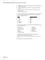
The following are standard features built into each PS shipping scale.
•
•
•
•
•
•
100 kg (PS6) or 45 kg (PS3) capacity “Eagle+” load cell
Die-cast aluminum base and sub-platter
Stainless steel or Plastic platter
RS-232 serial interface to the scale base
USB interface (PSXXU only)
Sleep mode for energy conservation (PSXXG only)
•
•
•
•
•
•
•
•
12 VDC, 60 mA power supply unit (wall-mount transformer)
D-cell alkaline battery KOP (for some models)
Car lighter jack
Ball transfer top platter
0270, 2-key weight indicator base mount display with 12 in. cable
Tower display with 14 ft cable
Wall mount display with 14 ft cable
Dual Wall mount displays with 6 ft cable
Optional Accessories
1-2 (08/04)
Chapter 1: Introduction
Specifications
Specifications
The PS shipping scale conforms to and operates best within the specifications
described in this section.
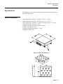
Physical Dimensions
•
•
•
•
•
•
•
•
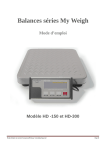
Base dimensions: 290 mm × 335 mm (11.42 in. × 13.19 in.)
Platter dimensions: 300 mm × 350 mm (11.81 in. × 13.78 in.)
Max. dimensions w/indicator: 358 mm × 350 mm (14.09 in. × 13.78 in.)
Height with platter: 80 mm (3.15 in.)
Height with platter and battery: 90 mm (3.54 in.)
Weight with display: 6.65 kg
Weight with display and battery: 7.75 kg
Shipping weight: 10 kg
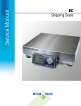
Figure 1-a: PS60 / PS6L Dimensions
Figure 1-b: PS60 Ball Transfer Dimensions
(08/04) 1-3
METTLER TOLEDO PS Shipping Scale Technical/Operators Manual
•
•
•
•
•
•
•
•
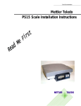
Base dimensions: 290 mm × 335 mm (11.42 in. × 13.19 in.)
Platter dimensions: 300 mm × 350mm (11.81 in. × 13.78 in.)
Maximum dimensions w/indicator: 358mm x 350mm (14.09in. x 13.71.in.)
Height with platter: 80 mm (3.15 in.)
Height with platter and battery: 90 mm (3.54 in.)
Weight (w/display, non-battery): 6.65 kg
Weight (w/display, w/battery): 7.75 kg
Shipping weight: 10 kg
Figure 1-c: PS30/PS3L Dimensions
Power Requirements
The PS operates over an input voltage range of 7.5 to 12 VDC (at 60 mA).
1-4 (08/04)
•
An external 9 VDC voltage converter supplies power to the PS.
•
An optional D-cell battery KOP can be used to power the scale
continuously for a minimum of 40 hours. Battery life is extended with the
on/off switch in the “off” position.
•
An optional 12 VDC Car Lighter Jack Cable can power the PS.
•
The PSXXU scale can be powered by the PC through the USB port.
Chapter 1: Introduction
Standards Compliance
Environmental
Requirements
The PS60 operating range is −10° to +40°C (+14°F to +104°F) at 10 to 90%
relative humidity, non-condensing. The PS30 and PS3L operating range is 0°
to 40°C (+32° F to +104°F) at 10 to 90% relative humidity, non-condensing.
The PS6L operation range is +10° to +40°C at 10 to 90% relative humidity,
non-condensing. The shipping and storage temperature range is −20° to
+60°C (-4°F to +140°F) at 0 to 95% relative humidity, non-condensing.
The scale is designed for use in parcel shipping and other light industrial
environments. This unit is not intended for washdown or hazardous area
operation, nor for operation in environments of extreme dust, heat, cold, or
humidity.
Standards
Compliance
The PS60 meets or exceeds USA NIST HB-44, Australian NSC, Canadian
MC, and international OIML requirements for a 3000 division, Class III parcel
scale.
The PS30 meets or exceeds USA NIST HB-44 for a 1400 division Class III
parcel scale, and Canadian MC requirements for a 3000 division Class III
parcel scale.
The PS6L meets or exceeds USA NIST HB-44 requirements for a 4800
division, Class III parcel scale.
The PS3L meets or exceeds USA NIST HB-44 requirements for a 0-7lb / 770lb (1120d/5600d) Class III multi-interval scale and Canadian MC
requirements for a 0-15kg / 15-30kg (3000d / 3000d) Class III multi-interval
scale.
AC Power Line Voltage
Variation
The PS meets USA NIST HB-44, Australian NSC, and Canadian MC line
voltage variation specifications as listed in the following table:
AC Line Voltage
Line Frequency in Hz
Line Voltage Variation
Specification
Minimum
Nominal
Maximum
Minimum
Nominal
Maximum
NIST HB-44
100
120
130
59.5
60
60.5
Australian NSC
102
120
132
58.8
60
61.2
Canadian MC
108
120
132
58.8
60
61.2
(08/04) 1-5
METTLER TOLEDO PS Shipping Scale Technical/Operators Manual
RFI Susceptibility
The PS60 meets the requirements of the European Norm. 45501 for RFI
susceptibility as listed below with a maximum of one display increment of
change when calibrated for recommended builds.
Radio Interference
Frequency
Field Strength
26-1000 MHz
3 volts/meter
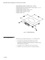
Electrical Interfaces
The PS scale’s single board construction has a load cell connector (10 position
ZIF), display connector (8 position phone jack), RS-232 interface (9-Pin
DSUB), and an input power jack. The following interconnection diagram
describes wiring connections for the PS shipping scale.
The PS can function as a peripheral device to a host through the RS-232 serial
port. Calibration and setup can be done using the Host Interface command set.
For detailed instructions describing calibration and setup using the Host
Interface, please refer to the Appendix at the end of this manual.
Figure 1-c: PS60G/PS30 Electronic Interface Diagram
1-6 (08/04)
Chapter 1: Introduction
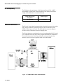
Electrical
Interfaces
Figure 1-d: PS6LH Electronic Interface Diagram
Figure 1-e: PS60U/PS30 Electronic Interface Diagram
1-7 (08/04)
FOR YOUR NOTES
Chapter 2: Installation and Calibration
Unpacking and Setup
.
2
Installation and Calibration
This chapter gives detailed instructions and important information you will
need to install the PS successfully. Please read this chapter thoroughly before
you begin installation. This information is also covered in the PS Operator
Instructions.
Unpacking and Setup
Please inspect the package as the carrier delivers it.
• If the shipping container is damaged, check for internal damage and file a
freight claim with the carrier if necessary.
• If the container is undamaged, open the box, remove the scale, and place it
on a solid, flat surface.
If you choose to dispose of the
package, please recycle the
materials.
The packaging is recyclable natural
fiber with biodegradable adhesives.
Please keep the packing material and shipping insert in case the scale needs to
be returned to METTLER TOLEDO. The PS is a precision instrument and
may be permanently damaged if not shipped in factory-approved packaging.
Typical package contents for the PS include:
•
•
•
•
•
•
•
PS Shipping Scale
Installation Instructions
Product Documentation CD
Power Supply
Optional Accessories
USB Cable (PS60U, PS6LU, PS30)
RS232 Cable
Installation
The PS shipping scale is fully assembled at the factory, and you should not
have to assemble the unit. To install components other than those installed at
the factory, please refer to Chapter 5 Service and Maintenance.
The proper environment enhances the
operation and longevity of the scale.
1. Locate a suitable environment for the scale. Refer to Chapter 1 for
environmental specifications.
2. Remove the packaging material from each side of the scale. Remove the
scale by grasping the bottom sides of the scale. Do not lift the scale by
grasping the sub-platter.
3. Place the scale on a sturdy, level surface and remove any protective
shipping materials under the platter.
(08/04) 2-1
METTLER TOLEDO PS Shipping Scale Technical/Operators Manual
4. Level the scale by turning the adjustable feet on the bottom of the unit.
When the bubble in the bubble indicator is within the circle, the PS is level
(see Figures 2-a, 2-b,). The feet must be adjusted so the scale does not
rock.
M
E
T
T
L
E
R
U
TN
I
O
LT
S VV
E
D
O
O
N
/
O
F
F
O
-
Leveling Feet (4)
Figure 2-a: PS,Leveling Feet
Incorrect
Bubble is not
within circle
Correct
Bubble is
within circle
Figure 2-b: Level Indicator
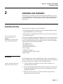
5. Unpack the power supply and plug it into the power jack in the scale base.
The jack is recessed on the bottom of the base toward the center front.
Plug the line cord into a properly grounded AC power outlet. Figure 2-c
illustrates proper power supply connection. Figure 2-d illustrates proper
power supply connection for USB models.
WARNING!
AC power sources must have proper short
circuit and over current protection in
accordance with local and national electrical
regulations. Failure to provide this may result in
bodily injury and/or property damage.
(08/04) 2-2
Chapter 2: Installation and Calibration
Initial Calibration using GeoCal
NOTE: Inside of barrel is positive.
Figure 2-c: Power Cable Connection
Figure 2-d: USB Connections
(08/04) 2-3
METTLER TOLEDO PS Shipping Scale Technical/Operators Manual
Basic Information
The following sections describe some basic information that you will need to
know as you install, calibrate, and use the PS in normal operating mode.
The Display
The PS’s display consists of six digits and five cursor positions. Each digit is
composed of seven segments and is 12 mm high. The PS’s cursor can appear
above one or more of the legends printed on the display to indicate the current
unit, stable conditions, zero, or options in setup mode.
The display area also indicates over-capacity and under-capacity conditions.
Over- and under-capacity are indicated on the display as follows:
< 0>
Over Capacity
< 0>
Under Capacity
Figure 2-e: Over/Under Capacity Display
Keys and Navigation
The PS keypad contains a UNITS key and a ZERO key:
UNITS
ZERO
0
Figure 2-f: UNITS and ZERO Key
(08/04) 2-4
Chapter 2: Installation and Calibration
Initial Calibration using GeoCal
The functions for each key in normal operating mode are as follows:
• UNITS—Press UNITS to switch between the selected main units and
alternate units.
• ZERO—Press ZERO to zero an empty scale. The reading must be within
2% of the calibrated zero.
If the scale is in Sleep mode (as defined in the Sleep program block), press
ZERO to “awaken” the scale. The scale then goes through its normal power-up
sequence and returns to normal operating mode.
The functions for each key in setup mode are as follows:
• UNITS—Press and hold UNITS for up to 8 seconds to enter setup mode.
When a program block option is displayed for selection, press UNITS to
confirm the selection.
• ZERO—Press ZERO to scroll through a list of parameter options.
(08/04) 2-5
METTLER TOLEDO PS Shipping Scale Technical/Operators Manual
Initial Calibration
using GEOCAL™
The PS shipping scale must be calibrated when the unit is initially installed to
correct for local gravity variations thereby ensuring accurate weighing results.
If the GEOCAL™ capabilities of your PS unit have been activated, the unit
has been pre-calibrated from the factory. If this is the case, the first time the
PS is powered up from the factory it should display the Geo in prompt as
follows:
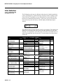
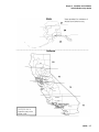
This indicates that you must select the code for your location. The latitude and
altitude of your location both effect gravity and the calibration of your scale.
Therefore, it is important to select the proper code. Refer to the table below in
order to determine the code for your area. If your location is not listed select
closest one.
GEOCAL™ Location Codes
State
Alabama
Birmingham & North
South of Birmingham
Alaska
Arizona
Phoenix & North
South of Phoenix
Arkansas
California
Colorado
Denver & North
South of Denver
Connecticut
Delaware
Florida
West Palm Beach & North
South of West Palm Beach
Georgia
Hawaii
Idaho
North of Salmon River Mtns
South of Salmon River Mtns
Illinois
Bloomington & North
South of Bloomington
Indiana
North of Indianapolis
Indianapolis & South
Iowa
North of Des Moines
Des Moines & South
(08/04) 2-6
Code
13
12
See map
12
11
13
See map
13
12
16
15
11
10
12
9
17
16
16
15
16
15
17
16
State
Code
State
Code
Kansas
Kentucky
Louisiana
Maine
Maryland
Massachusetts
Michigan
14
14
12
18
15
17
North Dakota
Ohio
Akron & North
South of Akron
Oklahoma
Oregon
18
Northwest of Lake Michigan
Southeast of Lake Michigan
Minnesota
Mississippi
Kosciusko & North
South of Kosciusko
Missouri
18
17
18
North of Springfield
Springfield & South
Montana
Helena & North
South of Helena
Nebraska
Nevada
New Hampshire
New Jersey
New Mexico
New York
Albany & North
South of Albany
North Carolina
Raliegh & North
South of Raliegh
15
14
13
12
18
17
15
13
17
16
11
17
16
14
13
Salem & North
Between Oakridge & Salem
South of Oakridge
Pennsylvania
Rhode Island
South Carolina
South Dakota
Tennessee
Texas
Northeast of Colorado River
Southwest of Colorado River
Utah
Vermont
Virginia
Washington, DC
Washington State
West Virginia
Wisconsin
Green Bay & North
South of Green Bay
Wyoming
North of Casper
Casper & South
16
15
13
18
17
16
16
16
13
17
13
12
11
13
17
14
15
18
15
18
17
15
14
Chapter 2: Installation and Calibration
Initial Calibration using GeoCal
(08/04) 2-7
METTLER TOLEDO PS Shipping Scale Technical/Operators Manual
The sequence for selecting your GEOCAL™ code is as follows:
1. Press the ZERO key to display the first code option and continue pressing
it to scroll through all of the available codes.
2. Press the UNITS key to select the code for your location. The display will
then prompt done. Press the UNITS key again to restart the scale.
Power-up Sequence
The PS goes through a power-up sequence each time power is applied or the
scale is brought from its power-down ("sleep") state. The scale performs a
diagnostic test on its ROM and RAM, then proceeds to normal operating
mode. The power-up sequence is as follows:
1. All segments of the display characters are activated. This verifies
operation of all segments.
To “awaken” the PS whenever it is in
sleep mode, press the ZERO key.
2. The scale displays the software part number followed by the software
revision status.
3. The scale then captures zero (if the zero reading is within ± 10% calibrated
capacity on power-up) and is ready for normal operation.
Full Calibration
WARNING
ONLY PERMIT QUALIFIED PERSONNEL TO
SERVICE THIS EQUIPMENT. EXERCISE CARE
WHEN MAKING CHECKS, TESTS AND
ADJUSTMENTS THAT MUST BE MADE WITH
POWER ON. FAILING TO OBSERVE THESE
PRECAUTIONS CAN RESULT IN BODILY HARM.
You can calibrate the PS scale using the UNITS and ZERO keys, or you can
calibrate the unit remotely from a computer terminal through its Host
interface. Details on calibration using a Host Interface are given in the
Appendix at the end of this manual.
To calibrate the PS at the scale:
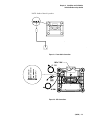
1. Disconnect the power from the scale.
2. Remove the platter, break the legal-for-trade seal (if present), and remove
the PCB cover plate to give access to the PCB.
3. Remove the calibration jumper (W1 in Figure 2-g / 2-h).
Note: PCB of PS6L looks slightly different but still has a Mlock jumper, W3.
(08/04) 2-8
Chapter 2: Installation and Calibration
Full Calibration
CAL Jumper W1
Figure 2-g: CAL Jumper on Main PSXXG PCB
Figure 2-h: CAL Jumper on Main PSXXU PCB
(08/04) 2-9
METTLER TOLEDO PS Shipping Scale Technical/Operators Manual
4. Connect the power to the scale.
This prompt only appears if the
calibration jumper is removed.
5. Enter the setup mode by pressing and holding the UNITS key for up to
eight seconds until the message Setup is displayed. Release the UNITS
key.
6. Press the UNITS key several times until the Cal prompt appears, then
press ZERO to display YES or NO. Select Yes to calibrate or select No to
abort calibration. If Yes, press UNITS to begin the calibration process.
7. Press UNITS to select the displayed approval option.
Press UNITS until the Alt prompt appears, then press ZERO to display the
desired primary and secondary units. Select from the following options: (Not
an option on PS6L)
8.
•
•
•
•
kg/kg
lb/lb
lb/kg
kg/lb
Calibration units are selected according to the scale build. For example, if
a scale has a kilogram build, select kg as the primary unit. Alternately, if
the scale has a pound build, select lb as the primary unit.
9.
If a different capacity/increment option
is selected, the Cal prompt
automatically appears.
Press UNITS to select the displayed units option.
Press UNITS until the Build prompt appears, then press ZERO to display
the desired capacity/increment option. Capacity/increment options include:
10.
Display Prompt
60-01
150-02
60-02
150-05
60-ni
200-ni
70-ni
PS60/PS60U
Build
60 x 0.01 kg
150 x 0.02 lb
60 x 0.02 kg
150 x 0.05 lb
60 x 0.01 / 0.02 kg Multi-Interval
200 x 0.05 / 0.1 lb Multi-Interval
70 x 0.02 / 0.05 kg Multi-Interval
PS6L
Note: The PS6L has only one Capacity/Increment build: 0-10 lb x 0.1 oz, 1070 x 0.2 oz, 70-150 lb x 0.5 oz.
PS30/PS3L
(08/04) 2-10
Chapter 2: Installation and Calibration
Full Calibration
Display Prompt
30-02
70-05
30-01
30-ni
70-ni
70-no
Build
30 x 0.02 kg
70 x 0.05 lb
30 x 0.01 kg
0-15 / 15-30 kg Multi-Interval
0-7 / 7-70 lb Multi-Interval
0-7 / 7-70lb/oz. Multi-Interval
11. Press UNITS to select the displayed capacity/increment option.
12. Press UNITS until the CAL prompt appears, then press ZERO to display
Y or N. Select Y(es) to calibrate or select N(o) to abort calibration. If
Y(es), press UNITS to begin the calibration process.
13. At the Empty prompt, set the empty platter on the sub-platter, then press
UNITS.
14. At the 50 lb, 20 kg, 125 lb, or 50 kg prompt, place on the platter a test
weight equaling one-third of the scale's capacity (50 lb or 20 kg), or
half of the scale’s capacity (125 lb or 50 kg) then press UNITS. The scale
automatically determines a span factor then indicates Done while the
calibration values are saved.
15. Disconnect the power from the scale. At the Empty prompt, insure that
the empty platter is on the sub-platter, then press UNITS.
16. Replace the calibration jumper (W1), then reassemble the scale.
The PS is now calibrated and ready to configure to your needs. Chapter 2 of
this manual gives setup and configuration details.
You can change the build from straight weighing to weight classifying as
follows:
1. Enter setup mode by pressing and holding the UNITS key for up to eight
seconds.
2. Press the UNITS key to display the Mode menu.
3. Press ZERO to display Classifr.
4. Press UNITS to display the End menu.
5. Press ZERO to display Save.
6. Press UNITS to return to normal operating mode.
(08/04) 2-11
METTLER TOLEDO PS Shipping Scale Technical/Operators Manual
Metrological Seal
Installation
If a wire seal is required for W & M requirements, the PS can be sealed after
calibration and setup by installing a wire seal on the Main PCB access cover,
as shown in Figure 2-i.
Figure 2-i: Wire Seal Installation
USB Installation
USB scale connection is very automatic. When you connect the scale to your
PC’s USB port, the PC will automatically sense the scale. Different versions of
Microsoft’s operating systems will vary the set-up slightly.
*** When using USB, the power adapter is not necessary. The scale will be
powered through the USB cable.***
Windows 98
The set-up for the USB drivers for Windows 98 is fairly automatic but MAY
require some interaction with dialog boxes to complete. You may be prompted
to insert your original Windows 98 CD in order to find the proper drivers.
Most Windows 98 systems will react just like Windows 2000 / XP. Here are
the messages you may see using Windows 98.
(08/04) 2-12
Chapter 2: Installation and Calibration
Full Calibration
A dialog box stating “New Hardware Found” will appear. Immediately, the PC
will begin to “Build Driver Information Database”.
1. Once this is complete, a “Add New Hardware” Wizard will
appear. Select the bottom choice of “Display a list of all the
drivers in a specific location, so you can select the driver you
want”.
2. If the drivers are not immediately found, insert your Windows
98 CD and locate the proper directory.
3. The “USB Human Interface Device” will appear as the default
driver.
4. Click on “OK” and then “Finish”
Windows 2000 / XP
This is more automatic. There are no choices to make. The PC will
automatically recognize the scale and install the appropriate driver. With no
human interaction required
(08/04) 2-13
FOR YOUR NOTES
Chapter 3: Configuring the Setup Parameters
Configuring Setup Parameters
3
Configuring the Setup Parameters
This chapter discusses basic information related to PS configuration and
specific instructions on configuring each program block and operating
parameter.
Basic Setup
Information
The following sections describe some basic information that you will need to
know as you configure the setup parameters for the PS.
Program Block Access
The PS’s operational parameters are configured in setup mode through a series
of program blocks. The program blocks are accessed as follows:
1. Press and hold the UNITS key for up to eight seconds until the message
Setup? is displayed. Release the UNITS key. When released, the PS
displays either the Pb 0 or Alt prompt indicating the first program block.
Exit Setup
Exit setup mode as follows:
1. Press UNITS to display the End prompt.
2. Press ZERO to display the desired exit option. Exit options include:
• No—Do not exit setup mode at this time.
• Save—Save all changes program block parameters then exit setup
mode.
• Abort—Exit setup mode but do not save any changes made in this
session.
• Various Defaults—Reset all program block parameters to a prespecified set of values, then exit setup mode. For details, refer to the
End Program Block section.
3. Press UNITS to carry out the displayed option. The PS automatically exits
setup mode and returns to normal operating mode unless No is selected.
There are two alternate ways to exit the setup mode:
• The scale automatically leaves the setup mode after it has been
calibrated.
(08/04) 3-1
METTLER TOLEDO PS Shipping Scale Technical/Operators Manual
• Disconnect the power from the scale. Changes will not be saved.
Configuring Setup
Parameters
This section describes the program blocks that govern normal operation
including:
•
•
•
•
•
•
•
•
Push Button Zero *
Zero Cursor *
Power-up Units *
Build *
Alternate Units
Mode *
Filter
Baud
•
•
•
•
•
•
•
•
ASCII
Parity
Stop Bits
Protocol
Sleep
GEOCAL™*
Calibration *
End
This is the order that they appear in the prompts.
* The Push Button Zero, Zero Cursor, Power-up Units, Capacity/Increment
(Build), Display Mode, GEOCAL™ Activation, and Calibrate program blocks
are hidden in setup mode when the Metrology PCB jumper (W1) is in place.
These program blocks are used only when the jumper is removed and the scale
is being calibrated. Please refer to Chapter 2 for calibration details.
The PS can also be configured remotely through the METTLER TOLEDO
Host Interface. Details for configuring the scale using the Host Interface are
given in the Appendix at the end of this manual.
To configure the PS at the scale, enter the setup mode by pressing and holding
the UNITS key for up to eight seconds until the message Setup is displayed.
Release the UNITS key, then configure the PS program block parameters.
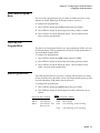
Push Button Zero
Program Block
The Push Button Zero program block lets you configure the range within
which the PS can capture zero. The push button zero capture ranges currently
supported are ± 2%, ± 5%, and ± 100%. (Metrology PCB jumper must be
removed.)
To configure the program block:
1. Press UNITS to display the Pb 0 prompt, then press ZERO.
2. Press ZERO to display the desired zero capture range.
3. Press UNITS again to accept the pct option. The PS continues to the Zero
Cursor program block.
(08/04) 3-2
Chapter 3: Configuring the Setup Parameters
Configuring Setup Parameters
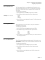
Zero Cursor Program
Block
The Zero Cursor program block lets you enable or disable the center of zero
indicator on the PS. (Metrology PCB jumper must be removed.)
To configure the program block:
1. Press UNITS to display the 0 CurS prompt, then press ZERO.
2. Press ZERO to display the desired approval setting, enable or disable.
3. Press UNITS to accept the displayed option. The PS continues to the
Power-up Unit program block.
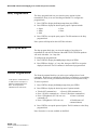
Power-up Unit
Program Block
The Power up Unit program block lets you select which units will be active on
the PS upon startup. This program block will effect the build options that are
seen in the Build program block.
To configure the program block:
1. Press UNITS to display the unitS prompt, then press ZERO.
2. Press ZERO to display the desired approval setting, pounds or metric.
3. Press UNITS to accept the displayed option. The PS continues to the
Build / Alternate Units program block.
Build Program Block
The build program block lets you chose a capacity and increment size setting
for the product based on the model you have purchased and the power-up units
selection. (Metrology PCB jumper must be removed.)
To configure the program block:
1. Press UNITS to display the buiLd prompt, then press ZERO.
2. Press ZERO to display the desired approval setting. Option may vary as
follows:
Power-up units = Pounds
150-02
150 x 0.02 lb.
150-05
150 x 0.05 lb. *
200-ni
150 x 0.05 lb., 150200 x 0.1 lb.*
PS60
Power-up units = Metric
60-01 60 x 0.01 kg
60-02 60 x 0.02 kg
60-ni
0-30 x 0.01 kg, 30-60 x 0.02 kg
70-ni
0-50 x 0.01 kg, 50-70 x 0.05 kg
(08/04) 3-3
METTLER TOLEDO PS Shipping Scale Technical/Operators Manual
PS6L
Power-up units = Pounds
149-ni
0-10 lb. x 0.1 oz, 10-70 lb. x 0.2 oz, 70-150 lb. x 0.5 oz *
150-n5
0-5 x 0.005 lb., 5-25 x 0.05, 25-150 x 0.1 lb.
Multi-interval PS30/PS3L
Power-up units = Pounds
70-05
70 x 0.05 lb.
70-ni
0-7 / 7-70 lb Multi-Interval
70-no
0-7 / 7-70 lb/oz. Multi-Interval.
Power-up units = Metric
30-01
30 x 0.01 kg
30-02
30 x 0.02 kg
30-ni
0-15 / 15-30 kg Multi-Interval
* Default for that model.
‘ni’ on the display represents Multi-Interval
‘n5’ on the display represents Multi-Interval with 0.005 lb. increment size
3. Press UNITS to accept the displayed option. The PS continues to the
Alternate Units program block.
Note: the scale can only be sealed in the build that is listed on the data label.
Alternate Units
Program Block
This program block lets you enable or disable unit switching during normal
operation.
To configure the program block:
1. Press UNITS to display the ALt prompt, then press ZERO.
2. Press ZERO to display the desired approval setting, enable or disable.
3. Press UNITS to accept the displayed option. The PS continues to the
Mode / Filter program block.
Mode Program Block
The Mode program block lets you configure which mode is used to display
weight. (Metrology PCB jumper must be removed.)
To configure the program block:
1. Press UNITS to display the nodE prompt, then press ZERO.
2. Press ZERO to display the desired mode. Options include:
• Normal
• Expanded – typically x10
• Classifier – weight classifier rounding
3. Press UNITS to accept the displayed mode option. The PS continues to the
Filter program block.
(08/04) 3-4
Chapter 3: Configuring the Setup Parameters
Configuring Setup Parameters
Filter Program Block
The Filter program block lets you configure the noise filter that is used in
determining weight stability on the scale. The PS disregards environmental
noise such as vibrations that affect the weighing accuracy according to the
filter setting.
To configure the program block:
1. Press UNITS to display the FiLtEr prompt, then press ZERO.
2. Press ZERO to display the desired noise filter. Options include:
Settling time increases with heavier
filter setting.
• Light
• Heavy
• Medium
3. Press UNITS to accept the displayed filter option. The PS continues to the
Baud program block.
Baud Program Block
This program block lets you set the baud rate (the speed at which data is
transmitted in bits-per-second).
To configure the program block:
1. Press UNITS to display the bAud prompt, then press ZERO.
2. Press ZERO to display the desired baud rate. Options include:
• 300
• 1200
• 2400
• 4800
• 9600
• 19200
3. Press UNITS to accept the displayed baud rate option. The PS continues to
the ASCII program block.
ASCII Program Block
The ASCII program block lets you select the number of bits that make up an
ASCII character. Most METTLER TOLEDO equipment communicates using
seven data bits.
To configure the program block:
1. Press UNITS to display the ASCii prompt, then press ZERO.
2. Press ZERO to display the desired bit selection. Options include:
• Seven (7)
• Eight (8)
3. Press UNITS to accept the displayed option. The PS continues to the
Parity program block.
(08/04) 3-5
METTLER TOLEDO PS Shipping Scale Technical/Operators Manual
Parity Program Block
The Parity program block lets you select the parity option for data
transmission. Parity is an error checking mechanism. To configure the
program block:
1. Press UNITS to display the PAr prompt, then press ZERO.
2. Press ZERO to display the desired parity option. Options include:
• Space
• Mark
• Odd
• Even
• None
3. Press UNITS to accept the parity option. The PS continues to the Stop
program block.
Note: options will depend on the ASCII bits selection.
Stop Program Block
The Stop program block lets you select the number of stop bits to be
transmitted for each ASCII character. Most METTLER TOLEDO products
will work with either 1 or 2 stop bits.
To configure the program block:
1. Press UNITS to display the StoP prompt, then press ZERO.
2. Press ZERO to display 1 or 2 stop bits, then press UNITS to accept the
displayed selection. The PS continues to the Protocol program block.
Protocol Program Block
Toledo protocol contained in the PS
is identical to the Toledo protocol
within the industrial builds of the
8213. The PS replaces the
industrial versions of the 8213.
The Protocol program block lets you select a pre-configured set of scale
commands. Protocols are configured in the factory according to your ordering
information. This section gives instructions on how to select a protocol only.
To select a protocol:
1. Press UNITS to display the Proto prompt, then press ZERO.
2. Press ZERO to display the desired protocol. Options include:
• Toledo (MT command set)
• Proto 4 (UPS command set)
• Proto 1 (Fed Ex command set) • Proto 5 (Purolator command set)
• Proto 2 (Weightronix SC-320 com. set)
• Proto 6 (Airborne
command set)
• Proto 3 (Weightronix 3870 com. set)
• Disable(turns off
communications)
3. Press UNITS to accept the protocol option. The PS continues to the Sleep
program block.
Note: Protocols 1-6 are not available on the PS6L.
(08/04) 3-6
Power is saved if RS-232 interface is
not used.
Chapter 3: Configuring the Setup Parameters
Configuring Setup Parameters
Sleep Program Block
The Sleep program block lets you configure the sleep timer. Power
consumption is reduced by approximately 60% while in Sleep mode.
IMPORTANT: For battery powered units, it is important to turn battery
power off (using the rocker switch underneath the scale) when the scale is
not in use.
To configure the Sleep program block:
In normal operating mode the scale is
powered-up by pressing the ZERO
(ON/OFF) key.
1. Press UNITS to display the SLEEP prompt, then press ZERO.
2. Press ZERO to display the desired sleep timer option. Options include:
• Disable—the PS will not power-down regardless of time between
transactions (inactivity)
• 5 min—the PS will enter Sleep mode after 5 minutes with no activity
3. Press UNITS to accept the sleep timer option. The PS continues to the
GEOCAL™ / End program block.
GEOCAL™ Program
Block
This program block lets you enable the GEOCAL™ prompt at power-up. If
this setting is enabled, the unit will prompt for the entry of a GEOCAL™ code
after setup is exited.
To configure the program block:
1. Press UNITS to display the GEo in prompt, then press ZERO.
2. Press ZERO to display the desired approval setting, enable or disable.
3. Press UNITS to accept the displayed option. The PS continues to the Cal
program block.
Calibration Program
Block
See Chapter 2 for detailed information about activating GEOCAL™ and
calibrating the PS. (Metrology PCB jumper must be removed.)
End Program Block
The End program block lets you save the configuration and exit setup mode.
This program block does not have parameters to configure.
To use the End program block:
1. Press UNITS to display the End prompt.
2. Press ZERO to display the desired exit option. Exit options include:
(08/04) 3-7
METTLER TOLEDO PS Shipping Scale Technical/Operators Manual
•
•
•
•
Default—Reset all program block parameters to standard MT values,
then exit setup mode.
Abort—Exit setup mode but do not save any changes made in this
session.
Save—Do not exit setup mode at this time. PS returns to the first
program block.
Def x—Company specific.
If you are using software from one of the following carriers your PS scale
can be completely configured for use by selecting one of the options
below (not available on PS6L):
Carrier
End prompt selection
• RPS
Default
• DHL
Default
• Fed Ex
Def 1
• UPS
Def 4
• Purolator
Def 5
• Airborne
Def 6
Choosing a default, rather the selecting SAVE, will automatically set the
following program blocks:
•
•
•
•
•
•
Zero Cursor
Power-up Units
Units Switching
Filter
BAUD
ASCII BIT String
•
•
•
•
•
PARITY
STOP BITS
Sleep Mode
Protocol
Display Mode
The PS6L only has the Default option. This is the standard MT
communications parameters and command set.
If your carrier is not listed try the default option, otherwise contact your
carrier.
3. Press UNITS to carry out the displayed option.
(08/04) 3-8
Chapter 3: Configuring the Setup Parameters
Configuring Setup Parameters
This page was intentionally left blank.
(08/04) 3-9
FOR YOUR NOTES
Chapter 4: Operating Instructions
Keypad and Display
4
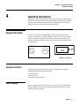
Operating Instructions
This chapter gives information that an operator will need to become familiar
with the scale and perform its functions in normal operating mode. The scale
operates based on the current program block configuration. Please refer to
Chapter 3 for more information on configuring the PS.
Keypad and Display
The PS has a simple LCD weight display with two keys that are used to
perform scale functions. Weight is displayed using up to six 7-digit numeric
characters with decimal point and comma. Cursors (horizontal bars) at the
bottom of the display indicate current weight units and zero condition when
zero is captured.
UNITS
ZERO
lb
Figure 4-a: PS Keypad
<0>
unit
0
kg
Å0 Æ
Figure 4-b: PS Display
Operator Functions
The PS supports one primary function: parcel weighing. Other operator
functions described in this chapter include:
• Unit switching
• Zero the scale
• Repower from Sleep mode
Parcel Weighing
Before weighing parcels on the PS, please be sure the scale is configured as
desired (Chapter 3) and power is applied as instructed in Chapter 2 of this
manual.To weigh a package:
(08/04) 4-1
METTLER TOLEDO PS Shipping Scale Technical/Operators Manual
You may wish to recapture zero
periodically when the scale is in
continuous use. It is not necessary to
press ZERO before each transaction.
1. Press ZERO to capture zero. The display reads 0.00 and a cursor appears
above the zero indicator in the legend.
2. Place the parcel to be weighed on the platter. The display reads the parcel
weight with a cursor above the current weight units legend.
3. Record the parcel weight, then remove the parcel from the platter.
Unit Switching
The PS lets you view the displayed scale weight in primary and secondary
units. Alternate units must be configured (in setup mode) to convert and
display in alternate units.
If primary and alternate units are the
same (as configured in the Alternate
Units program block), unit switching
is effectively disabled. The UNITS key
displays the same weight and unit
when the UNITS key is pressed.
To switch units:
1. With scale weight displayed, press the UNITS key. The PS automatically
converts the displayed weight to weight in the alternate unit as indicated
by the cursor.
2. Press UNITS again to reconvert alternate units back to primary units and
return weight display to the primary unit.
Zeroing the Scale
If zero change exceeds the 2% limit,
the scale will not capture zero. In this
case, cycle power or recalibrate.
Periodically the PS scale may need to be re-zeroed. Press ZERO to capture
zero. The scale will re-zero provided the weight is within 2% of the scale
capacity. The PS display will read 0.00
Repowering from Sleep
If the PS display is blank after a period of inactivity, the ZERO key “awakens”
the unit from its power-saving (sleep) mode.
When the ZERO key is pressed, the PS goes through its power-up sequence
and returns to normal operating mode.
4-2 (08/04)
Chapter 5: Service and Maintenance
Cleaning and Regular Maintenance
5
Service and Maintenance
This chapter gives information on servicing, upgrading, and maintaining the
PS including cleaning and regular maintenance, troubleshooting, and installing
optional equipment kits.
Cleaning and Regular
Maintenance
You may need to wipe the keypad and platter with a clean, soft cloth that has
been dampened with a mild cleaner. Do not use any type of industrial solvent
such as toluene or isopropanol (IPA). These may damage the display finish.
Do not spray cleaner directly onto the terminal.
Troubleshooting
The PS shipping scale is designed to be virtually error free and reliable. If
problems do occur, do not attempt to repair the scale before you have
determined the source of the problem. Record as much information as possible
about what has happened including any messages and physical responses. The
following troubleshooting information may help to determine the cause of the
problem.
WARNING
DISCONNECT ALL POWER TO THIS UNIT BEFORE
INSTALLING, SERVICING, CLEANING, OR REMOVING THE
FUSE. FAILURE TO DO SO COULD RESULT IN BODILY
HARM AND/OR PROPERTY DAMAGE.
CAUTION
OBSERVE PRECAUTIONS FOR HANDLING
ELECTROSTATIC SENSITIVE DEVICES.
(08/04) 5-1
METTLER TOLEDO PS Shipping Scale Technical/Operators Manual
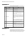
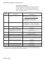
Error Code Section
Error codes are displayed on the weight indicator with a leading “E” to
distinguish themselves from weight data.
Code
Meaning
E1
ROM (checksum) error
E2
RAM error
Action
Replace the circuit board to clear this error (call
Mettler Toledo Service)
Replace the circuit board to clear this error (call
Mettler Toledo Service)
Setup and /or calibration information has been lost.
Press any display button and the scale will enter setup
mode or calibration mode depending on what
information is lost.
E3
If both setup and calibration information has been
lost, the scale will enter setup mode first when a
display button is pressed. After completing the setup,
the scale will display E3 again until a button is
pressed to enter calibration mode and calibration is
completed.
EEPROM error
Reset the setup parameters and/or recalibrate to clear
this error. If the scale continues to display E3 after
the setup and/or calibration has been completed, the
load cell is unable to save the information and will
need to replaced (call Mettler Toledo Service)
E4
E5
TC error
Replace the load cell to clear this error (call Mettler
Toledo Service)
Serial Communications (Data) error
The scale has received a character from the host with
an invalid parity. The scale will display E5 until
either a display button is pressed or another character
is received. This error could be caused by an
incorrect Baud Rate or Data Bits selection in the scale
setup.
Wall Transformer
The wall transformer (when connected to the proper AC input and
disconnected from the scale) may read as high as 12.8 VDC. The wall
transformer should read from 9 VDC, up to 13 VDC when connected to the
scale. If the voltage measured is not within this range, replace the wall
transformer. The center conductor of the wall transformer is positive.
(08/04) 5-2
Chapter 5: Service and Maintenance
Troubleshooting
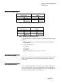
Main PCB (PS60G only)
From PC - DB25-F RS232
To PS - DB9-M
SERIAL PORT
(Male)
2
TRANSMIT
3
RECEIVE
3
RECEIVE
2
TRANSMIT
7
SIG
1 or 5
SIG
GROUND
GROUND
Table 1 Standard PC RS232 DB-25 To PS
From PC - DB9-F RS232
To PS – DB9-M
SERIAL PORT
(Male)
2
RECEIVE
2
TRANSMIT
3
TRANSMIT
3
RECEIVE
5
SIG
1 or 5
SIG
GROUND
GROUND
Table 2 Standard PC RS232 DB9 To PS
To test the Main PCB: (Unit must be setup for standard MT communications
(Default)):
1. Start your communications software such as ComTool (Part Number
KN000000K64).
2. Setup your software for:
•
•
•
•
7 data bits
Even parity
1 stop bit
Baud rate that matches the computer’s baud rate
Blank or Half Display
Remove power then check the display interface harness from the scale to the
display. Apply power the unit. If the blank display continues, replace the
0270 Display.
No Keypad Interaction
To test operation of the keypad, remove power, then reapply. With power to
the unit, and the W1 (W3 on PS6L) calibration jumper installed, attempt to
enter setup mode by pressing and holding the UNITS key. If the display does
not indicate setup mode, replace the 0270 Display.
(08/04) 5-3
METTLER TOLEDO PS Shipping Scale Technical/Operators Manual
Indicator Locked
To test operation of the indicator, remove power, then reapply. With power to
the unit, add weight. If no motion is displayed, replace either the load cell or
the Logic PCB.
Load Cell
Replacement
For load cell replacement, please use current revision of 15302300A for PS60
(3000d) , 17035300A for PS60G (3000d), and use 15828000A for PS60 multiinterval and PS6L versions (2x3000d), and 17035600A for PS60G multiinterval, and use 15354000A for PS30 and PS3L.
Loadcell replacement will require a model number to be installed. Once the
model is set, it cannot be changed without replacing the cell.
PS60G ONLY
At power-up the PS6 checks for a valid Scale Model Number in EEPROM. If
the Scale Model field is corrupted (or has not been programmed) the scale
displays an EEPROM error (E3). Once either key is pressed, the scale will
enter Scale Model selection mode and display:
"nOdEL?"
By pressing either key and the first model selection is displayed:
"PS6O "
(Model PS-60, standard version)
"PS6OEP"
(Model PS-60, 2x3000 version)
"PS6L "
(Model PS-6L)
Each time the Zero Key is pressed the next model selection is displayed.
Pressing the Units Key will store the displayed scale model as the new Scale
Model number. The default setup selections for the model selected are then
stored into EEPROM and the scale then reboots.
Installing the Battery Kit
The following instructions describe battery installation (alkaline cell) for the
PS shipping scale (PS60 model only). Under normal operation, battery life is
approximately 40 hours. Sleep mode reduces power consumption by 60% and
extends battery life. For prolonged battery life, turn the scale off when not in
use. Rechargeable Ni-Cad batteries can also be used.
NOTE:
BATTERY KIT WILL NOT WORK ON USB MODELS (PSXXU)
(08/04) 5-4
Chapter 5: Service and Maintenance
Installing the Battery Kit
WARNING!
Always remove all power before operating on any equipment.
Mettler-Toledo recommends that only qualified technicians open the
unit up for maintenance and repair. If you must open the PS, read
this section carefully to avoid damage to the internal components.
1. Remove the power and turn the PS over on the on the platter side. Be
extremely careful not to damage the display.
2. Install the plastic D-cell battery holder P/N 13257500A. Attach with four
M3-0.5X8 Pan HD screws and washers. Note the polarity of the battery
holder and terminal positions.
Terminal
Ends
3. Attach the harness assembly (P/N 14544600A) to the battery holder.
(08/04) 5-5
METTLER TOLEDO PS Shipping Scale Technical/Operators Manual
4. Insert the on/off rocker switch (P/N 14262400A) into the switch hole of
the battery cover (P/N 14545200A) noting the orientation of the switch.
Six alkaline 1.5 VDC, D-size batteries
(P/N 13293700A) are required for
operation.
5. Insert the two fasteners (P/N 12051300A) into the battery cover.
6. Install the terminal spade lugs on the terminals of the switch that is
installed into the battery cover.
7. Connect the plug into the receptacle on the Logic PCB as shown below
and install the six 1.5 VDC, D-size batteries.
(08/04) 5-6
Chapter 5: Service and Maintenance
Installing the Battery Kit
8. Carefully attach the battery cover paying close attention to the routing of
the cable to the Main PCB. Close the battery cover fasteners.
Open
(08/04) 5-7
METTLER TOLEDO PS Shipping Scale Technical/Operators Manual
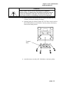
Installing the Base
Mount Display
A base mount display unit (0270, 2-key indicator) can be installed if one was
not ordered initially for the PS shipping scale (PS60 and PS6L models only).
To install the base mount display:
1. Attach the display unit to the bottom of the PS with the two M4 10mm
screws (P/N R0550100A) as shown below:
2. Install the display interface harness from the display as shown. Insert the
display interface harness into the PCB as shown. Make sure to route the
cable as shown to prevent damage to the cable.
(08/04) 5-8
Chapter 5: Service and Maintenance
Installing the Ball Top Transfer Platter
Installing the Ball Top
Transfer Platter
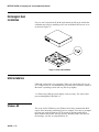
A ball top transfer platter is available for the PS. To install the ball transfer
platter:
1. Remove the platter supplied with the PS.
2. Place the ball top transfer platter on the PS.
3. Ensure that the ball top transfer platter drops into place without
mechanical interference.
Note: If the unit fails to capture zero after power-up, re-calibration will be
required.
(08/04) 5-9
FOR YOUR NOTES
Chapter 6: Parts and Accessories
PS60/PS6L/PS60U
6
Parts and Accessories
Please refer to the following diagrams and parts lists when ordering parts and
accessories for the PS shipping scale.
(08/04) 6-1
METTLER TOLEDO PS Shipping Scale Technical/Operators Manual
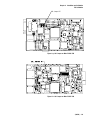
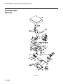
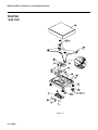
PS60/PS6L/PS60U
Scale Parts
Figure 6-a
6-2 (08/04)
Chapter 6: Parts and Accessories
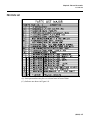
PS6 Parts List
PS6 Parts List
(*) Some part numbers may have a revision letter in front of them.
(**) Indicates not shown if Figure 6-a.
(08/04) 6-3
METTLER TOLEDO PS Shipping Scale Technical/Operators Manual
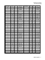
PS30/PS3L
Scale Parts
Figure 6-b
6-4 (08/04)
Chapter 6: Parts and Accessories
PS3 Parts List
PS3 Parts List
(*) Some part numbers may have a revision letter in front of them.
(**) Indicates not shown in Figure 6-b.
(08/04) 6-5
METTLER TOLEDO PS Shipping Scale Technical/Operators Manual
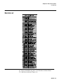
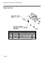
Weight Display Parts
Parts List—Weight Display
Ref #
Part Number
Description
1A
*15705300B
Display PCB Assembly W/Cable
1
1B
*15640800A
Display Base
1
1C
R0550100A
Screw,M4X10,PH,THD,w/Washer
2
(*) Some part numbers may have a revision letter in front of them.
6-6 (08/04)
Qty
Appendix A: Host Interface
Communication Parameters
Appendix A: Host Interface
The METTLER TOLEDO PS shipping scale can function as a peripheral
device to a host computer. In host mode you can:
• Calibrate the scale
• Configure setup parameters
• Request and receive weight data when the scale is in a stable state
The scale does not reply to host
weight commands if it is in calibration
mode or if the scale cannot capture
zero on power-up.
• Request and receive the scale’s status when the scale is in an unstable or
invalid state
• Zero the scale and/or switch units (depending on setup)
This section presents information and instructions on how to use the PS in host
mode.
Communication
Parameters
Data is transmitted and received by the scale through an RS-232 serial port
connection. The following communication parameters are supported:
•
•
•
•
•
Baud Rate (300, 1200, 2400, 4800, 9600, 19200)
Parity (no, even, odd, mark, space)
ASCII bit string (7 or 8)
Stop bits (1, 2)
The scale only responds to commands, continuous data output is not
available.
Protocols
The scale can be programmed to respond to a selected “menu” of defined
protocols. The host sends requests to the scale in the form of ASCII data and
control characters as determined by the selected protocol. The scale responds
to the host with a string of ASCII characters. ASCII characters and their binary
conversions are listed in the following table:
(08/04) Appendix A-1
METTLER TOLEDO PS Shipping Scale Technical/Operators Manual
ASCII Characters and Conversions
ASCII CHAR.
DEC
HEX
76543210
ASCII CHAR.
DEC
HEX
76543210
NULL
0
00
00000000
SPACE
32
20
00100000
SOH
1
01
00000001
!
33
21
00100001
STX
2
02
00000010
”
34
22
00100010
ETX
3
03
00000011
#
35
23
00100011
EOT
4
04
00000100
$
36
24
00100100
ENQ
5
05
00000101
%
37
25
00100101
ACK
6
06
00000110
&
38
26
00100110
BELL
7
07
00000111
’
39
27
00100111
Backspace
8
08
00001000
(
40
28
00101000
TAB
9
09
00001001
)
41
29
00101001
Line Feed
10
0A
00001010
*
42
2A
00101010
Vert. Tab
11
0B
00001011
+
43
2B
00101011
Form Feed
12
0C
00001100
,
44
2C
00101100
Carr. Return
13
0D
00001101
-
45
2D
00101101
Shift Out
14
0E
00001110
.
46
2E
00101110
Shift In
15
0F
00001111
/
47
2F
00101111
Data Link Esc
16
10
00010000
0
48
30
00110000
DC1
17
11
000010001
1
49
31
00110001
DC2
18
12
00010010
2
50
32
00110010
DC3
19
13
00010011
3
51
33
00110011
DC4
20
14
00010100
4
52
34
00110100
NAK
21
15
00010101
5
53
35
00110101
SYNCH IDLE
22
16
00010110
6
54
36
00110110
End Trans.
23
17
00010111
7
55
37
00110111
CANCEL
24
18
00011000
8
56
38
00111000
End Of Medium
25
19
00011001
9
57
39
00111001
Substitute
26
1A
00011010
:
58
3A
00111010
ESCAPE
27
1B
00011011
;
59
3B
00111011
FS (Cur. Right)
28
1C
00011100
<
60
3C
00111100
GS (Cur. Left)
29
1D
00011101
=
61
3D
00111101
RS (Cursor Up)
30
1E
00011110
>
62
3E
00111110
US (Cur. Down)
31
1F
00011111
?
63
3F
00111111
Appendix A-2 (08/04)
Appendix A: Host Interface
Scale Status Byte Format
ASCII CHAR.
DEC
HEX
76543210
ASCII CHAR.
DEC
HEX
76543210
@
64
40
01000000
`
96
60
01100000
A
65
41
01000001
a
97
61
01100001
B
66
42
01000010
b
98
62
01100010
C
67
43
01000011
c
99
63
01100011
D
68
44
01000100
d
100
64
01100100
E
69
45
01000101
e
101
65
01100101
F
70
46
01000110
f
102
66
01100110
G
71
47
01000111
g
103
67
01100111
H
72
48
01001000
h
104
68
01101000
I
73
49
01001001
i
105
69
01101001
J
74
4A
01001010
j
106
6A
01101010
K
75
4B
01001011
k
107
6B
01101011
L
76
4C
01001100
l
108
6C
01101100
M
77
4D
01001101
m
109
6D
01101101
N
78
4E
01001110
n
110
6E
01101110
O
79
4F
01001111
o
111
6F
01101111
P
80
50
01010000
p
112
70
01110000
Q
81
51
01010001
q
113
71
01110001
R
82
52
01010010
r
114
72
01110010
S
83
53
01010011
s
115
73
01110011
T
84
54
01010100
t
116
74
01110100
U
85
55
01010101
u
117
75
01110101
V
86
56
01010110
v
118
76
01110110
W
87
57
01010111
w
119
77
01110111
X
88
58
01011000
x
120
78
01111000
Y
89
59
01011001
y
121
79
01111001
Z
90
5A
01011010
z
122
7A
01111010
[
91
5B
01011011
{
123
7B
01111011
\
92
5C
01011100
|
124
7C
01111100
]
93
5D
01011101
}
125
7D
01111101
^
94
5E
01011110
~
126
7E
01111110
_
95
5F
01011111
127
7F
01111111
(08/04) Appendix A - 3
METTLER TOLEDO PS Shipping Scale Technical/Operators Manual
Toledo Protocol Host Commands
Following is a listing of host commands and scale responses. Brackets “<>”
are used to indicate that the characters within are a description of the
transmitted data and are not part of the transmitted data string. <STX>
indicates an ASCII Start Of Text character (HEX 02). <CR> indicates an
ASCII Carriage Return (HEX 0D).
Host
Command
Description
W*
Send normal resolution weight data.
<STX>XXX.XX<CR> (for PS60 lb builds) or
<STX>XXXlbXX.Xoz<CR> (for PS6L 150 lb-oz build)
For PS6L 150 x 0.005 lb Multi-Range build)
<STX>XX.XXX<CR> (x 0.005 lb increment)
<STX>XXX.XX<CR> (x 0.05 lb increment)
<STX>XXXX.X<CR> (x 0.1 lb increment)
<STX>?<StatusByte><CR> (if current weight is invalid)
H
Send high resolution weight data.
<STX>XXX.XXX<CR> (for PS-60 lb builds) or
<STX>XXXXXX<CR> (for PS6L 150 lb-oz build) or
<STX>XXX.XXX<CR> (for PS6L 150 x 0.005 lb build)
<STX>?<StatusByte><CR> (if current weight is invalid)
Z
Zero scale unless in motion or out of range
under or over capacity.
<STX>?<status byte><CR>
Scale status byte.
A
Perform a confidence test of RAM, ROM,
and EEPROM. Store results of tests in
confidence status byte for later retrieval.
<STX><CR>
The scale echoes back a <STX><CR> indicating the
command was received.
B
Send results of confidence test.
<STX>?<confidence byte><CR>
Confidence test status byte.
C
Initiate host interface scale configuration.
<STX>CALIBRATE?<CR>, See below
S
Initiate host interface setup.
<STX>SETUP?<CR>, See below
E
Enter “echo” serial port test mode. All
characters sent to the scale will be echoed
back to the host. “F” terminates the test.
<STX>E<CR>
The scale echoes back the letter E indicating the command
was received.
F
Exit “echo” serial port test mode.
<STX>F<CR>
The scale echoes back the letter F indicating the command
was received.
L
Switch to and send standard weight.
Same as for W above.
K
Switch to and send metric weight.
Same as for W above.
Scale Response
Table Note:* A status byte message <STX>?<status byte><CR> is sent in place of the requested weight data field if the scale is in
motion, under zero, or over capacity when the weight data request is sent. The question mark “?” indicates that the following data is a
non-ASCII status byte rather than weight data. See below for status byte definitions.
Appendix A-4 (08/04)
Appendix A: Host Interface
Scale Status Byte Format
Scale Status Byte
Format
When communicating in host mode using the standard Toledo protocol, the PS
may send status bytes containing information such as motion and over/undercapacity conditions. The message <STX>?<status byte><CR> indicates
transmission of a status byte. The status byte sent is an ASCII character that
must be converted to binary form for decoding the bits. The ASCII character
table with binary conversion (given in the previous section) can be used to
convert status bytes. The bits of the status byte in the standard Toledo protocol
are defined as follows:
Status Byte
Bit No.
Bit Description
6
Always 1
5
Always 1
4
1 = Center of zero
0 = Not at center of zero
3
1 = Outside zero capture range
0 = Within range
2
1 = Under zero
0 = Within weighing range
1
1 = Over capacity
0 = Within weighing range
0
1 = Scale in motion
0 = Stable weight data
Scale Confidence
Byte Format
When communicating in host mode using the standard Toledo protocol, the
host may ask the PS to store and send confidence bytes containing information
about RAM, ROM, and EEPROM testing. The message <STX>?<confidence
byte><CR> indicates transmission of a confidence byte. The confidence byte
sent is an ASCII character that must be converted to binary form for decoding
the bits. The ASCII character table with binary conversion (given in the
previous section) can be used to convert status bytes. The bits of the
confidence byte in the standard Toledo protocol are defined as follows:
(08/04) Appendix A - 5
METTLER TOLEDO PS Shipping Scale Technical/Operators Manual
Status Byte
Bit No.
Bit Description
6
1 = New status data available.
0 = Host has read data.
5
Bit is always a 0.
4
1 = ROM test failed.
0 = ROM test passed.
3
1 = RAM test failed.
0 = RAM test passed.
2
Bit is always a 0.
1
1 = Calibration Required.
0 = Calibration Data OK
0
1 = EEPROM test failed
0 = EEPROM test passed.
Calibrate Using Host
Interface
The PS shipping scale can be calibrated using the host interface. The command
to initiate the calibration sequence is available in the METTLER TOLEDO
command set. Calibration is based on the current scale configuration for units
and capacity/increment. These can be changed (through the keypad or the host
interface) before calibrating the scale through the host interface.
To calibrate using the host interface:
1. Remove the platter, break the legal-for-trade seal (if present), and remove
the sub-platter to give access to the PCB.
2. Remove the calibration jumper (W1). Refer to the calibration diagram in
Chapter 2 of this manual. DO NOT ENTER SETUP MODE. The PS does
not respond to host commands in calibration mode.
3. Send the command C to initiate calibration sequence. The scale responds
<STX>CALIBRATE?<CR><LF>.
4. Send the command Y to continue with the calibration sequence, or send
the command N to abort the sequence. The scale responds
<STX>UNLOAD SCALE- Y?<CR><LF>.
5. Remove any weight on the platter and send the command Y to continue. A
stable zero reading is taken, then the scale responds <STX> ADD 50 LBY? <CR><LF> or <STX> ADD 20 KG- Y? <CR><LF> or <STX>
ADD 125 LB- Y? <CR><LF> or <STX> ADD 50 KG- ? <CR><LF>.
Appendix A-6 (08/04)
Appendix A: Host Interface
Scale Status Byte Format
6. Add the requested calibration weight to the scale, then send the command
Y to continue. The scale responds <STX> CAL DONE <CR><LF> or
<STX> INCORRECT AMOUNT OF WEIGHT <CR><LF>.
Configure Scale
Parameters Using
Host Interface
Configuration parameters can also be sent using the host interface. A
command to send a new scale configuration over the host interface is available
in the METTLER TOLEDO command set.
To configure using the host interface:
1. From the host computer, send the host command S to initiate the
configuration setup sequence. The scale responds with the current set
bytes:
<STX>X1X2X3X4X5X6X7X8X9X10X11X12X13X14X15X16X17X18X19X20<CR>
2. Determine the command string representing the configuration parameters
that are desired. The command string consists of 22 characters beginning
with an ASCII <STX> and terminated with an ASCII <CR>. The
command string represents a 10-byte bit-mapped setup array stored in
EEPROM. The 10-byte array is expanded for serial transmission so that
the high-order four bits of each byte are zeroes and the low-order four bits
are numbers representing the desired option for each program block. See
the table below for definitions of each byte.
(08/04) Appendix A - 7
METTLER TOLEDO PS Shipping Scale Technical/Operators Manual
The table below lists the programming options available in each program
block as they are used in Host Interface Setup. When downloading the scale
setup it is strongly recommended that you modify only the selections that you
need to change in the current setup bytes sent by the scale. Leave the values of
all other setup bytes as they were when sent from the scale (including the
selections that are currently not used). Then send the modified setup bytes
string back to the scale.
X1 = Not Used, Set to 0x00.
X2 = Not Used, Set to 0x00.
X3 = Not Used, Set to 0x00.
X4 = GEO Entry Required:
0x01 = GEO Entry Required OFF
0x02 = GEO Entry Required ON
X5 = Units Switching:
0x01 = Units Switching OFF
0x02 = Units Switching ON
X6 = Zero Cursor:
0x01 = Zero Cursor OFF
0x02 = Zero Cursor ON
X7 = Not Used, Set to 0x00.
X8 = Sleep Mode:
0x01 = Sleep Mode OFF
0x02 = Sleep Mode ON
X9 = Serial Port Protocol:
0x01 = Disabled
0x02 = Mettler Toledo
0x03 = FedEx
0x04 = Weightronix WT320
0x05 = Weightronix WT3870
0x06 = UPS
0x07 = Purolator
0x08 = Airborne
X10 = Stop Bit:
0x01 = One Stop Bit
0x02 = Two Stop Bits
X11 = Parity Bit:
0x01 = Space Parity Bit
0x02 = Mark Parity Bit
0x03 = Odd Parity Bit
0x04 = Even Parity Bit
0x05 = No Parity Bit
Appendix A-8 (08/04)
X12 = Data Bits:
0x01 = 7 Data Bits
0x02 = 8 Data Bits
X13 = Baud Rate:
0x01 = 300 Baud
0x02 = 1200 Baud
0x03 = 2400 Baud
0x04 = 4800 Baud
0x05 = 9600 Baud
0x06 = 19200 Baud
X14 = Weight Filter:
0x01 = Light Filter
0x02 = Medium Filter
0x03 = Heavy Filter
X15 = Weight Display Mode:
0x01 = DLC Echo Test Mode
0x02 = Expanded (X10) Weight Display
0x03 = Normal Weight Display
0x04 = Weight Classifier Display
X16 = Power up Units:
0x01 = Metric (kg)
0x02 = Pounds (lb)
X17 = PS6 Scale Build:
0x01 = 60 x 0.01 kg / 150 x 0.02 lb
0x02 = 60 x 0.02 kg / 150 x 0.05 lb
0x03 = 100 x 0.05 kg / 250 x 0.1 lb
0x04 = 50 x 0.01 kg / 100 x 0.02 lb
0x05 = 60 x 0.02 kg / 150 x 0.05 lb Multi-Range
0x06 = 70 x 0.05 kg / 149 lb x 0.1 oz Multi-Range
0x07 = 150 x 0.005 lb Multi-Range
X17 = PS3 Scale Build
0x01 = 30 x 0.02 kg / 70 x 0.05 lb
0x02 = 30 x 0.01 kg / 70 x 0.02 lb
0x03 = 0-15 x 0.005 kg, 15-30 x 0.01 kg / 0-7 x
0.01 lb, 7-70 x 0.02 lb
0x04 = 0-15 x 0.005 kg, 15-30 x 0.01 kg / 0-7 lb x
0.1 oz., 7-70 lb x 0.2 oz.
X18 = Not Used, Set to 0x00.
X19 = Pushbutton Zero Capture Range:
0x01 = +/- 2% of scale capacity
X20 = Not Used, Set to 0x00.
Appendix A: Host Interface
Scale Status Byte Format
You can obtain the current
configuration by sending the S
command. Then you can abort
without changing by sending the A
command to abort.
Before sending the DONE reply, the
configuration file is analyzed just as if
it had been constructed using the
keyboard.
3. Send the command desired new set of bytes to the scale:
<STX>Y1Y2 ... Y19Y20<CR>
4. The scale will check to make sure the requested bytes are valid, then will
echo the request:
<STX>Y1Y2 ... Y19Y20<CR>. Or, if there were
problems with the request, the scale returns the original, unmodified setup
bytes to let the host know there was a problem:
<STX>X1X2 ... X19X20<CR>
5. Send the command Y to continue and store the new setup bytes and the
scale will respond with <STX>DONE<CR> when configuration is
complete or <STX>ABORT<CR> if the modified bytes had problems.
NOTE: At any time the Host can send an N command to abort the Setup
Download mode.
(08/04) Appendix A - 9
FOR YOUR NOTES
Appendix B: USB Host Interface
The USB 1.1 full speed (12Mbs) interface on this scale is used in applications
where a USB interface, which conforms to the Microsoft™ USB POS HID, is
required.
References
The following documents can be found on the official USB Web page.
http:/www.usb.org/developers/docs.html
Universal Serial Bus Specifications, Revision 2.0
http:/www.usb.org/developers/hidpage.html
Universal Serial Bus Device Class Definition for Human Interface Devices
(HID), Version 1.11
Universal Serial Bus HID Usage tables, Version 1.11
Universal Serial Bus HID Point of Sale Usage Tables, Version 1.02
Hardware
The contents to the host via a standard full speed (12Mbs) USB interface
cable. This cable will connect to a Series B type receptacle on the scale.
Electrical Connection
The scale supports one USB 1.1 full speed interface (12Mbs). Refer to
Universal Serial Bus Specification Revision 2.0 for details on signal
termination, signal levels and other electrical specifications for the USB
interface.
Power
The PS scale can be considered bus powered as a low power device because it
consumes less than 1 unit load of power (<100ma) with up to two non-backlit
displays or one backlit display connected. It does not fully comply with the
USB specifications because it does not support the “suspend state”.
(08/04) Appendix B-1
Protocol
This interface supports the standard Universal Serial Bus HID Point of Sale
Usage Tables for scales. Refer to the Universal Serial Bus HID Point of Sale
Usages Tables document for details on this protocol.
(08/04) Appendix B-2
FOR YOUR NOTES
METTLER TOLEDO
1900 Polaris Parkway
Columbus, Ohio 43240-2020
P/N: E15402600A
(08/04)
METTLER TOLEDO®is a Trademark of Mettler-Toledo, Inc.
© 2004 Mettler-Toledo, Inc.
Printed in U.S.A.