1
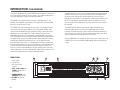
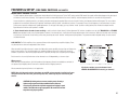
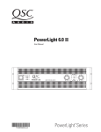
POWERLIGHT 2A
User Manual
Manuel de l’utilisateur
Bedienhandbuch
Manual del Usario
PL2A Audio Power Amplifiers
with Analog Signal Processing
*TD-000089-00*
TD-000089-00
Rev.B
•
•
•
•
PL218A
PL224A
PL230A
PL236A
EXPLANATION OF GRAPHICAL SYMBOLS
The lightning flash with arrowhead symbol within an equilateral triangle is intended to alert the user to the presence of uninsulated “dangerous” voltage within the
product’s enclosure that may be of sufficient magnitude to constitute a risk of electric shock to humans.
The exclamation point within an equilateral triangle is intended to alert the user to the presence of important operating and maintenance (servicing) instructions in the
literature accompanying the product.
CAUTION
RISK OF ELECTRIC SHOCK
DO NOT OPEN
CAUTION: To reduce the risk of electric shock, do not remove the cover. No user-serviceable parts inside.
Refer servicing to qualified personnel.
WARNING: To prevent fire or electric shock, do not expose this equipment to rain or moisture.
FCC INTERFERENCE STATEMENT
NOTE: This equipment has been tested and found to comply with the limits for a class B digital device, pursuant to part 15 of the FCC rules. These limits are designed to provide
reasonable protection against harmful interference in a residential installation. This equipment generates, uses, and can radiate radio frequency energy and if not installed and used in
accordance to the instructions , may cause harmful interference to radio communications. However, there is no guarantee that interference will not occur in a particular installation. If
this equipment does cause harmful interference to radio or television reception, which can be determined by switching the equipment off & on, the user is encouraged to try to correct
the interference by one or more of the following measures:
- Reorient or relocate the receiving antenna.
- Increase the separation between the equipment and the receiver.
- Connect the equipment into an outlet on a circuit different from that to which the receiver is connected.
- Consult the dealer or an experienced radio or TV technician for help.
© Copyright 2000, 2007 QSC Audio Products, Inc.
QSC® is a registered trademark of QSC Audio Products, Inc.
PowerLight™ is a trademark of QSC Audio Products, Inc.
“QSC” and the QSC logo are registered with the U.S. Patent and Trademark Office
All trademarks are the property of their respective owners.
2
TABLE OF CONTENTS
Explanation of Graphical Symbols.......................................................2
CONNECTIONS:
Inputs................................................................................21
Outputs............................................................................22
FCC Interference Statement....................................................................2
SECURITY PANEL USE & INSTALLATION...................................................24
INTRODUCTION:
PL2A Series Overview.................................................4
Front Panel...................................................................4
Rear Panel....................................................................5
Side Panel....................................................................5
FEATURES & SETUP:
Rear Panel SwitchesINPUT CONFIGURATION..............................................6
MODE...........................................................................7
DATAPORT INPUT SIGNAL..........................................8
GAIN-SENSITIVITY SELECT.........................................9
OPERATION:
Gain Controls................................................................25
AC Power Switch...............................................................25
Front Panel LED Indicators.................................................25
Normal operating levels......................................................25
TROUBLESHOOTING.......................................................................................26
TECHNICAL OVERVIEW & BLOCK DIAGRAM............................................28
SPECIFICATIONS..............................................................................................30
Side Panel Switches and SIP networksSubaudio Filter & Subaudio Frequency....................10
Lo Frequency Delay and HF ATTEN..................................11
HORN BOOST.............................................................12
POWER LIMITER........................................................13
CLIP LIMITER..............................................................15
Crossover & Delay SIP Networks.............................16
WARRANTY INFORMATION..........................................................................32
HOW TO CONTACT QSC AUDIO PRODUCTS..............................................32
BLANK SETUP SHEETS...................................................................................33
DataPort, Front Panel LEDs, Gain ControlsBasic Overview...........................................................18
INSTALLATION:
Rack mounting & Mounting Dimensions.................19
Fan Cooling & AC Mains..........................................20
3
INTRODUCTION: PL2A OVERVIEW
Thank you for the purchase of your new POWERLIGHT 2A amplifier. To get the most
out of your amplifier, review this manual carefully. The installation and operation
sections provide proper connection and operation guidelines.
The POWERLIGHT 2A expands upon the features of the POWERLIGHT 2. The
flexibility, user-friendliness and reliability of this amplifier will make it a valuable
part of your system for years to come.
The POWERLIGHT 2A was designed to fit your system. You can adjust the input
sensitivity to match the output capability of your mixing board. DataPort input
signals can be summed before or after internal processing so that conflicts with
external processing are avoided. The 4th order Linkwitz-Riley crossover has
independent adjustment of crossover frequency and defeatable low-pass delay
time. The high-pass side of the crossover includes separate binary adjustments for
trim and driver EQ. The precision limiters provide separate adjustment of limiter
threshold, peak mode and attack/release times. You can adjust the limiter
threshold between 100% and 3% of available power. The limiters have a gentle
limiting knee which preserves a sense of signal dynamics. In bi-amplified systems,
a slower attack/release time can be used on the low frequency channel. The
limiters can also be connected together to maintain stereo balance in full range
mode or frequency balance in bi-amplified mode. A peak limiting mode with a fast
attack time provides protection for fragile high frequency drivers.
FRONT PANEL
1. Power switch
2. Cooling vents
3. Gain control (1 per
channel)
4. CLIP, -10 dB, -20 dB and
SIGNAL indicator LEDs, 1
per channel
5. POWER, BRIDGE, and
PARALLEL indicator LEDs
6. BI-AMP indicator LED
7. Handles
4
The POWERLIGHT 2A is easy to use. All operating mode switches are grouped
together on the rear panel. These critical switches have color-coded LED’s to
positively confirm switch position. A brilliant blue LED on the front clearly
indicates when the amplifier is in bi-amp mode. Limiter threshold, high-pass trim
(HF ATTEN) and high-pass EQ (HORN BOOST) levels use combinations of two
position switches for easy adjustment. These less used switches are located on
the side panel.
The POWERLIGHT 2A is built for the long haul. Rubber-isolated XLR input
connectors reduce stress on the contact pins and provide a tight, noise-free
connection. All signal processing is done in side loops and then returned to the
main signal path. This maintains high signal fidelity and provides a more robust
system in the unlikely event a processor ceases to function.
Your new POWERLIGHT 2A amplifier will give you many years of great sound. The
POWERLIGHT 2A is the most flexible, durable and best performing amplifier you
can buy.
INTRODUCTION: PL2A OVERVIEW
REAR PANEL
1.
DataPort
2.
Terminal block inputs
3.
Configuration switches
4.
XLR inputs
5.
Speakon outputs
6.
Binding post outputs
7.
Cooling air inlet vents
8.
Serial number label
9.
IEC connector for AC power cord
9a.
Power cord retaining clip (install on item 8)
SIDE PANEL
1.
Low pass delay network SIP* socket (J5)
2.
Crossover frequency network SIP socket (J4)
3.
Subaudio filter push-button switches (1 per
channel)
4.
Subaudio filter “on” indicator LEDs (1 per channel)
5.
DIP** switch for subaudio filter frequency select,
low frequency delay enable, HF attenuation
and horn boost
6.
DIP switches for power limiting adjustments
and clip limiting enable
7.
Activity LEDs for indication of power limiter
activity (1 per channel)
*SIP is the abbreviation for Single-In-line Package
**DIP is the abbreviation for Dual-In-line Package
Side cover plate removed for this illustration
5
FEATURES & SETUP- REAR PANEL SWITCHES: INPUT CONFIGURATION
INPUT CONFIGURATION- This switch selects between STEREO or PARALLEL
input configuration. The indicator LED’s above the switch confirm the switch setting.
STEREO: Each input is sent to its respective channel. Each channel has
independent subaudio filtering, clip limiting, gain control, and outputs. In
STEREO mode, a full-frequency signal may be presented to each channel.
When to use STEREO input configuration: Use STEREO for stereo
sources (L-R inputs) and any other situation that requires each channel to
be completely separate from the other.
PARALLEL: The CH 1 and CH 2 inputs are connected together, applying a
single input signal to both channels of the amplifier. A signal into any
input jack will drive both channels. Each channel's subaudio filtering, clip
limiting, and gain control still function independently. Each channel feeds
its own speaker load.
You can patch the input signal on to additional amplifiers (“daisy-chain”)
by using any of the remaining input jacks. This feature eliminates the
need for “Y” cables.
The orange PARALLEL LED on the front panel clearly indicates when the
amplifier in configured for PARALLEL input.
When to use PARALLEL input configuration: Use PARALLEL when
you need one signal to drive both channels.
NOTE: Ensure that the INPUT CONFIGURATION
switch is set to STEREO when feeding two
separate signals to the two channels.
6
NOTE: The “normal” position of the MODE
switch is 2 CH when operating in STEREO or
PARALLEL input for the operating conditions
shown above. See the following section for
more information regarding the MODE switch.
FEATURES & SETUP- REAR PANEL SWITCHES: MODE
MODE- This switch selects between BI-AMP, 2 CH, or BRIDGE modes of operation.
The indicator LED’s above the switch confirm the selection.
BI-AMP: This puts the amplifier into a “crossover” mode. CH 1 receives
the low frequencies and CH 2 is receives the high frequencies. The
crossover is a 4th order Linkwitz-Riley. The crossover frequency and lowfrequency alignment delay are “programmed” with SIP (single in-line
package) resistor networks . These small plug-in networks are installed
from the side of the amplifier and plug into J4 and J5. WARNING: Do not
insert or remove networks with the power turned on. See the SIP Network
Selection and Installation section for more information. The HF ATTEN,
HORN BOOST, and SUBAUDIO FILTER controls are active in BI-AMP
mode. The blue BI-AMP LED on the front panel indicates when the amp
is in bi-amp mode.
When to use BI-AMP mode: Use BI-AMP when you need to split the
high frequency and low frequency signals to power separate driver types.
2 CH: This is the “normal” mode used for stereo and parallel input
configuration. Each channel carries full-frequency signals (no crossover)
and is independently controlled (gain, processing, output connection).
BRIDGE: This mode combines both output channels into one output. This
mode is for driving a single, high-powered load with twice the “normal”
voltage swing. This results in about 4 times the peak power and about
three times the sustained power of a single channel. This mode uses the
input, gain control, subaudio filter, and clip limiter of CH 1; CH 2's filter
and clip limiter have no effect. The yellow BRIDGE LED on the front panel
indicates when the amp is in BRIDGE mode.
When to use BRIDGE mode: Use BRIDGE mode when you need to
deliver the power of two channels to a single 8 or 4 ohm load, such as a
subwoofer. Do not use less than 4 ohm loads in BRIDGE mode.
BRIDGE MODE OUTPUT CONNECTIONNote that speaker connection for bridge mono mode is different than other modes.
See section on Connections: Outputs for proper bridge mode output connections.
7
FEATURES & SETUP- REAR PANEL SWITCHES: DATAPORT INPUT SIGNAL
DATAPORT INPUT SIGNAL- This switch selects the regular inputs or the
DataPort inputs, and allows the DataPort to enter before or after the analog
processing. WARNING: There is no DataPort “flag” for this setting, so the appropriate
setting must be confirmed manually.
OFF: If the DATAPORT CONNECTION is not being used, set to the OFF position. The
DataPort MONITOR SIGNALS and STANDBY are still active, but the DataPort input signals
will not reach the amplifier.
PRE PROC: This setting will insert the DATAPORT signals ahead of the amplifier’s signal
processor. If you are using external processing on the DATAPORT input signal, be aware that
additional internal processing will be added to the signal. This may cause unexpected overall
results.
POST PROC: This selection inserts the DATAPORT signals after the amplifier’s processor.
The subaudio filters and clip limiting remain functional, but all other processing is
bypassed. See the Block Diagram for more detailed signal flow information.
DATAPORT signal routing options using the DATAPORT INPUT SIGNAL switch
8
FEATURES & SETUP- REAR PANEL SWITCHES: GAIN-SENSITIVITY SELECT
GAIN-SENSITIVITY SELECT- This switch selects the gain structure of the amplifier. Each channel
runs through a gain buffer which allows all models to have either a uniform 1.2 Vrms input sensitivity or
a uniform 26 or 32 dB of voltage gain (all measured with the GAIN controls at maximum). The internal
signal leaving this stage is approximately +4 dB, leaving about 16 dB of headroom for the rest of the
signal processing. NOTE: The GAIN-SENSITIVITY SELECT setting does not effect DataPort gain in any
mode.
1.2 Vrms: This selection sets the input sensitivity to approximately 1.2 Vrms.
This is the input voltage required to drive the amplifier to rated output power
into an 8 ohm load.
26 dB: This selection sets the maximum voltage gain of the amplifier to
approximately 26 dB.
32 dB: This selection sets the maximum voltage gain of the amplifier to
approximately 32 dB
9
FEATURES & SETUP- SIDE PANEL SWITCHES: SUBAUDIO FILTER and SUBAUDIO FREQUENCY
The side panel cover plate must be removed to access the side panel switches.
CH1 SUBAUDIO FILTER, CH2 SUBAUDIO FILTER- These push-button switches are used
to turn on or off the SUBAUDIO FILTER for each channel. Press the switch in for ON; the green
LED illuminates when the filter is ON. Push in and allow the switch to release for OFF; the green
LED extinguishes when the filter is OFF.
The filter’s roll-off frequency is determined by each channel’s SUBAUDIO FREQUENCY switch.
When the filter is switched OFF, a 5 hertz roll-off frequency protects the load against DC or deep
subaudio output from the amplifier. Unless you already have filtering upstream of the amplifier,
use the SUBAUDIO FILTER to protect your speakers from cone over-excursion caused by
frequencies below the speaker’s limits. The OFF position should be used only for subwoofer
systems with rated frequency response below 30 hertz or if low frequency filtering is provided by
other devices.
CH1 SUBAUDIO FREQUENCY, CH2 SUBAUDIO FREQUENCY- These switches
determine the low frequency roll-off of the SUBAUDIO FILTER. Generally, match the frequency
selection to your speaker’s low frequency capability. This improves speaker performance by
limiting subaudio cone movement, making more power available for the speaker’s rated
frequency range. 30 Hz and 50 Hz are the available settings. If the SUBAUDIO FILTER switches
are OFF, these settings will have no effect. These switches are located on sections 1 and 10 of
the left-most DIP switch.
Subaudio filter frequency response- filter on, 50 hertz selected
10
Subaudio filter frequency response- filter off
Subaudio filter frequency response- filter on, 30 hertz selected
FEATURES & SETUP- SIDE PANEL SWITCHES: LO FREQ DELAY and HF ATTEN
LO FREQ DELAY- This switch is active only when the amplifier is in BI-AMP mode. This
switch controls an additional analog delay which adds to the inherent delay of the low
frequency filter. The amount of delay is determined by the SIP programming network installed
in the DELAY NETWORK socket (J5). DELAY OFF disables the delay. ENABLE LO FREQ
DELAY activates the delay. Refer to the SIP network value selection chart for more
information.
HF ATTEN- These switches are active only when the amplifier is in BI-AMP mode.
These four switches (section 3, 4, 5, and 6 of the left-most DIP switch) work in
combination to control the amount of high-frequency attenuation. The amount of
attenuation can be selected in 1dB steps from 0 to 15 dB. Add the selected switch values
for the total attenuation. EXAMPLE: Setting -1 dB and -4 dB results in -5 dB of high
frequency attenuation.
Typical crossover frequency response curve showing
the range of adjustment of the HF ATTEN switches.
Crossover frequency is programmable.
11
FEATURES & SETUP- SIDE PANEL SWITCHES: HORN BOOST
HORN BOOST- These switches are only active when the amplifier is in BI-AMP
mode. These switches work in combination to control the amount of high-frequency horn
boost. The horn boost is adjustable from 0 to 14dB in 2dB steps as measured at 20 kHz.
Add the values of the selected switches for the total boost.
12
FEATURES & SETUP- SIDE PANEL SWITCHES: POWER LIMITER
POWER LIMITER: Each channel has its own limiter with independently adjustable threshold and time constants. A ten-section switch for each channel controls the limiter settings.
LIMITER ACTIVITY LED’s: Just below the CH 1 and CH 2 labels you will note a clear circle which has a yellow
LED behind it. Each LED illuminates only when its limiter is reducing gain. Therefore, the LED activity tells you
how hard the limiter is working and shows the limiter time constant (see SPEED).
POWER LIMITER ENABLE: Set this switch to ON to activate the limiter for each channel. NOTE: The Limiter
Activity LED does not illuminate until the output power reaches the limiter threshold.
POWER LIMITER MODE:
AVG mode tracks the program level with moderate attack and release rates (SPEED is set
below). This setting does not respond strongly to isolated peaks and therefore gives the
smoothest results.
Limiter adjustment DIP switches.
Settings shown are for example only.
PEAK mode causes limiting to increase abruptly, even on short peaks. It provides faster
protection, but causes more audible “ducking” of the program level.
POWER LIMITER THRESHOLD: These four switches control the threshold where limiting begins in 1 dB steps
relative to the amplifier’s rated power. The limiting characteristic has a soft knee which begins several dB below
the threshold. The threshold is reached at 6 dB of limiting. Slope is 8:1 on AVG mode, and 15:1 on PEAK mode.
To enter the desired power, find the amplifier’s rated power at your load impedance (see Specification
section), determine the desired percentage of power and consult the table at right to convert this to the nearest
dB setting. Then combine switch settings to obtain the desired setting.
EXAMPLE: You want limiting to occur at 100 watts, using a 4 ohm load. You are using a PL230A
which is rated for 900 watts into 4 ohms. Therefore, you want to limit at 11% of this power. This falls between 9 dB and -10 dB on the table (below). We enter -10 dB by setting the -8 dB and -2 dB switches.
POWER LIMITER SPEED, ATTACK-RELEASE: Three overall response times or “speeds” are available.
Although it may seem desirable to have rapid response in all cases, a limiter should not change gain appreciably
during an individual cycle of audio, as this causes intermodulation (IM) distortion. Therefore the speed must be
slow enough to pass the lowest frequency intended, without unwanted modulation. Otherwise the low frequency tones cause “garbling” of the highs. The speed settings adjust the release time which governs how much
the limiter can change from one cycle to the next. The AVG mode (described above) has a 25% attack time
relative to this release time, so the gain changes gradually in both directions. The PEAK mode has a 1 to 2%
attack time and therefore gain reduction can occur quickly for more protection. However, gain increase is still
controlled by the overall SPEED setting, and therefore, the same frequency range applies.
NOTE: The time constants for each setting are determined by internal capacitor values which can be
changed by a qualified service technician. Consult QSC Technical Services for more information.
Power limiter switch settings for all possible combinations
13
FEATURES & SETUP- SIDE PANEL SWITCHES: POWER LIMITER (continued from previous page)
FAST- Set both POWER LIMITER SPEED switches to FAST. This setting produces 20 milliseconds (0.020 seconds) of release time. The AVG mode will produce 8 milliseconds of
attack time, and PEAK mode will produce less than 1 millisecond of attack time. This setting will have low distortion down to about 1 kHz. It is suitable for high frequency protection,
but will cause a distinctly “muddy” effect when used on full range material.
MED- Set the upper POWER LIMITER SPEED switch to MED and the lower switch to FAST. This setting produces 200 milliseconds of release time. The AVG mode produces 80
milliseconds of attack time and the PEAK mode produces 10 milliseconds of attack time. This setting is the fastest possible setting for full range material and may still produce some
IM distortion for extremely low frequencies.
SLOW- Set the lower POWER LIMITER SPEED switch to SLOW and the upper switch to FAST. This setting provides 4 seconds of release time. The AVG mode produces 1.6
second of attack time and the PEAK mode produces 180 milliseconds of attack time. This setting will change the gain very gradually in the AVG mode, and sudden peaks may clip for
1 to 2 seconds. The PEAK mode will push overloads down quickly, but recovery time will still take many seconds.
POWER LIMITER TRACKING- Each channel’s power limiter operates independently, with its own threshold and time constants.
Four tracking modes are available for your use:
1- No Tracking-- switch section 9 of both limiter adjustment DIPs should be set to OFF. This is the “usual” mode where neither channel’s limiting effects the other.
2- CH 1 tracks the limiter activity of CH 2-- switch section 9 of channel 1’s limiter adjustment DIPs should be set to TRACK CH 2 and switch section 9 of channel 2’s limiter
adjustment DIPs should be set to OFF. This tracking mode is not often used, but is applied to paging environments with high ambient noise levels. Limiting on channel 2 will cause
limiting to occur on channel 1. Channel 2 is set up for a vocal-range horn and carries the voice page; its limiter is set for MED speed and PEAK mode with a power threshold and
gain setting that produces proper paging level. Channel 1 is set up for a full-range music speaker with its level set for comfortable listening against the ambient noise. When a
page drives channel 2 into limiting, channel 1 is driven “down” also, making the page more audible against the background noise. Some experimentation with channel 2’s gain and
threshold will be required for best performance with a range of paging voices & levels.
3- CH 2 tracks the limiter activity of CH 1 (bi-amp tracking) -- switch section 9 of channel 2’s limiter adjustment DIPs should be set to TRACK CH 1 and switch section 9 of
channel 1’s limiter adjustment DIPs should be set to OFF. This tracking mode is useful for high frequency bi-amping , using fast protection on the horn without “ducking” the low
frequencies. When used carefully, this mode can protect each driver in a two-way system , while preserving musical dynamics and balance.
We offer the following suggestions as a starting point for bi-amp tracking:
TWO-WAY SPEAKER WITH A FAIRLY HIGH CROSSOVER FREQUENCY- Most of these systems have a large cone low frequency driver and a comparatively delicate high frequency
driver. The limiting is tailored for each driver; higher power threshold and slower limiter speed for the low frequency driver and a lower power threshold and faster limiter speed for
the high frequency driver.
The low frequency driver can handle short time overloads, so its limiter can be set to the slower responding AVG (average) mode with MED to SLOW overall limiting times. Short
peaks may clip, but the overall limiting will be smooth and gradual with no low frequency distortion and a minimum of “ducking”. If there is too much clipping, try the CLIP
LIMITER or use the PEAK mode and MED speed.
14
FEATURES & SETUP- SIDE PANEL SWITCHES: CLIP LIMITER
POWER LIMITER TRACKING- continued
The high frequency driver requires a lower power threshold and fast limiting response. Try the FAST setting and the PEAK mode. Short peaks will be limited aggressively, but signals
will return to normal almost instantly. This response (fast with low threshold) would have too much “ducking” and low frequency distortion for use with full range material.
Once each driver has optimal protection, you need to make them work properly together. When only one channel is limiting, the frequency balance will be upset. This may not be a
problem with some material, but testing is required. The different tracking “modes” offer different solutions. For example, if the crossover frequency is low, both drivers may have
similar power capacities and protection speed requirements. For this type of bi-amping, you may find that “mode” 4 (stereo tracking, below) offers the best sound performance.
Experimentation with the actual speakers is needed.
4- Each channel tracks the other (stereo tracking)-- switch section 9 of both channel’s limiter adjustment DIP switches should be set to the right (TRACKS CH 2 and TRACKS
CH 1). Stereo playback usually uses matched speakers and thus if one channel limits, it will effect the image and placement of the instruments. When each channel tracks the other,
any limiting on one channel causes limiting on the other, preserving the overall “balance” while protecting the speakers. The power threshold and speed settings for each channel
should be matched.
CLIP LIMITER: The PL2A amplifier also has separate limiters which respond only to amplifier clipping. These
may be used with or without the adjustable Power Limiters.
When the audio signal drives the amp's output circuit beyond its power capability, the amp clips and flattens the
peaks of the waveform. The clip limiter detects this and quickly reduces the gain to minimize the amount of
overdrive. To preserve as much of the program dynamics as possible, limiting occurs only during actual clipping.
Each channel has its own clip limiter that can be switched on or off independently, as shown at right.
When to use itWhen driving full-range speakers, clip limiting reduces high frequency distortion caused by bass overloads. It
also protects high frequency drivers from excess overdrive and harsh clipping harmonics.
We recommend using the clip limiters in all applications.
Clip limiter switches are at the bottom of each
LIMITER ADJUSTMENT DIP switch (1 per channel)
NOTE: After all side panel switches have been set and SIP resistor networks installed, verify your
setup and reinstall the side cover plate to keep dirt, dust, and foreign objects from entering the
chassis.
CAUTION: Clip limiting reduces extreme overdrive peaks, allowing a
higher average signal level without audible distortion. However,
increasing the gain with the clip limiter engaged, until clipping is again
audible, can double the average output power. Be careful not to exceed
the power rating of your speakers.
15
FEATURES & SETUP- SIDE PANEL: CROSSOVER & DELAY NETWORK SELECTION & INSTALLATION
SIP RESISTOR NETWORK INSTALLATION GUIDELINES AND SELECTION
INFORMATION
DECODING SIP NETWORK RESISTANCE VALUES
(see note below decoding chart)
Your PL2A amplifier is shipped configured to order with SIP networks installed. If
the factory set up is not applicable for your application,then you will need to
know your desired crossover frequency and low frequency delay time in order to
select the corresponding SIP resistor network values. Refer to the selection
chart, below, for nominal crossover frequency and delay values.
A general guideline would be to never use a larger value of delay SIP than
that used for the crossover. After choosing the desired values from the
selection chart, locate the plastic bag containing the SIP networks and locate
the desired value.
NOTE: Due to the number of manufacturers of SIP resistor networks, we can not
possibly provide examples of all the various part number marking schemes. We have
provided the three most common marking schemes, above. If the SIP networks you have
received do not conform to one of the above schemes, QSC’s Technical Services
Department will be glad to assist you in determining the resistance value of your SIPs.
Alternatively, you could measure the resistance value with a multimeter; simply set you
meter to the proper resistance range and connect your multimeter’s leads to the first two
pins of either end to obtain the value.
16
FEATURES & SETUP- SIDE PANEL: CROSSOVER & DELAY NETWORK SELECTION & INSTALLATION
Turn the power to the amplifier off before removing or installing SIPs!
The SIPs may be installed “either way”. The
SIPs are symmetrical and thus perform
identically no matter which end points to the
left or right. This completely eliminates
“polarity” errors that might otherwise arise.
The side cover plate must be removed to access
the SIP sockets. Be sure to reinstall the side
cover plate after installing the SIPs.
Before installing the SIP (as shown right) ensure
that the pins are straight. This will ease
insertion into the jack and help to avoid
damaging the pins due to misaligned insertion.
NOTE: Reinstall the side
cover plate after SIP
installation to keep dust, dirt,
and foreign objects from
entering the internal
circuitry of the amplifier.
Failure to do so could result
in damage to the amplifier
should any such material
enter the chassis.
17
FEATURES & SETUP: DATAPORT,
FRONT PANEL LED INDICATORS, GAIN CONTROLS
DATAPORT CONNECTOR
The PL2A amplifier features a QSC DataPort connector which connects to accessory products to enhance your amplifier application.
The CM16a Amplifier Network Monitor can remotely control and monitor your PL2A amplifier. The DSP-3 digital signal processor can
mount directly to the rear of your PL2A amplifier, adding an incredible amount of processing power in a small, powerful module at a
very competitive price.
WARNING: The PL2A amplifiers use a rear panel switch ( DATAPORT INPUT SIGNAL switch) to control the input
signal from the DataPort. When using a DataPort-connected accessory, be sure to set this switch to PRE PROC
(blue confirmation LED illuminated) or POST PROC (yellow confirmation LED illuminated) as desired. This switch
must be in the OFF position (green confirmation LED illuminated) to use the regular inputs.
OTHER ACCESSORIESAccessories for the PL2A amplifiers are available through your local distributor or directly from QSC. For accessory information,
contact QSC's Technical Services Department or your QSC representative. Check QSC’s web page for the latest product information.
FRONT PANEL LED INDICATORS
At full brightness, the green POWER LED indicates that the amplifier is operating. Half brightness indicates the
amp is in its start-up sequence or that the amplifier is in STANDBY mode.
As the input signal strength increases, the green SIGNAL, -20dB, and amber -10dB LED indicators light
respectively at 0.1%, 1% and 10% of full power. The red CLIP LED indicator flashes during overload (clipping). A
bright, steady glow indicates protective muting. If this occurs during use, see the Troubleshooting section. The
yellow BRIDGE LED illuminates when the amp is in BRIDGE mode. The blue BI-AMP LED illuminates when the
amplifier is in BI-AMP mode. The orange PARALLEL LED illuminates when the amp is in PARALLEL input mode.
GAIN CONTROLS
The gain controls are detented (21 steps) for repeatable adjustment. Surrounding the gain control knob, the
attenuation level is shown in dB. Maximum gain depends on the model and the GAIN-SENSITIVITY SELECT
switch setting. For full details, see the specification section.
18
DataPort connector location
Front panel: gain controls and indicator LED’s for
signal level, clip indication, power status indication,
and operating mode (bridge, parallel, bi-amp)
INSTALLATION: RACK MOUNTING AND MOUNTING DIMENSIONS
Before installing into equipment rack: ensure that all side-access DIP
switches and crossover SIPs are setup as desired. They will be
impossible (or extremely difficult) to change after the amplifier is
installed in the rack. The side cover plate should be installed to keep
dust and foreign material out of the chassis.
Securing the Front Ears to the Rack Rails
Use four screws and washers when mounting the PL2A amplifier to the front rails.
Support the weight of the amplifier while securing it to the rails to avoid bending or
distorting the front rack mount ears.
Supporting the Rear of the Amplifier
Supporting the amplifier at the rear is important, especially for mobile and touring
use. Rear rack mounting ear kits are an accessory item and are available from QSC’s
Technical Services Department or from your dealer or distributor.
The rear rack mounting ear kit may be installed in two
different ways.
Method 1- The amplifier is first installed from the front
of the rack and then the ears are secured directly to the
amplifier with two machine screws as shown, left. Then
the ears are secured to the rails using ordinary rail
hardware.
PL2 A rack mounting installation and major
dimensions
Method 2- The amplifier is first installed from the front
of the rack. Then, the accessory rear ears are positioned
on the rear rack rails and secured. The pin installation
position can now be selected. Install the pin so that it fits
well into the slot provided on the amplifier's rear
mounting tab.
PL2 A dimensional details
19
INSTALLATION: FAN COOLING & AC MAINS
FAN COOLING
The fan varies speed automatically to maintain safe internal temperatures and minimize noise. Keep the front
and rear vents clear to allow full air flow.
Hot air exhausts out the front of the amp so it does not heat the interior of the rack. Make sure that plenty of
cool air can enter the rack, especially if there are other units which exhaust hot air into it.
Keep the front and rear vents clear to allow full air flow. Make sure that plenty of cool
air can enter the rack, especially if there are other units which exhaust hot air into it.
Air flow in QSC amplifiers
OPERATING VOLTAGE (AC mains)
The correct AC line voltage is shown on the serial number label. Connecting to the wrong line voltage is dangerous and may damage the amplifier. The power cord attaches to the IEC
connector on the rear panel. Use the cord supplied with the amplifier, or an equivalent. Insure that the wire gauge of the cord is #14AWG. Use of smaller wire gauges can reduce the
line voltage available to the amplifier. A power cord retaining clip is provided with the amplifier. We recommend you install and use the retaining clip to prevent accidental power cord
disconnection.
Use the best possible connection to the AC power source. Avoid extension cords as they will cause some voltage drop between the AC source and you amplifier. If the use of an
extension cord is required, ensure that it is the largest wire size available (smaller gauge number means larger wire size). Ensure that all grounding connections are maintained.
The correct AC line voltage is shown on the serial number label.
Connecting to the wrong line voltage is dangerous and may damage the amplifier.
20
CONNECTIONS:
INPUTS
INPUTS
Each channel has active balanced "Euro-style" terminal block and XLR jacks wired in parallel. The input impedance is 12 kOhm balanced or 6 kOhm unbalanced. Each channel's input
jacks are wired in parallel. Unused input jacks may be daisy-chained to additional amplifiers if desired.
Balanced connection is recommended. Balanced signals are less prone to AC hum, but unbalanced signals can be suitable for short cable runs. The signal source's output impedance
should be less than 600 Ohms to avoid high frequency loss in long cables.
shield
Balanced inputs: Use the XLR or
the detachable terminal blocks.
Proper connection for balanced input
options are shown at right.
XLR connection•Balanced•Symétrique•Symmetrisch•Balanceado
Terminal block balanced • bloc
détachable symêtrique • symetrische
Anschlußstecker • Entrada de bloque
balanceado
jumper 1 to 3
shield
Unbalanced inputs: Connect the
unused side of the balanced input to
ground, as shown in the illustrations
for unbalanced connections, right.
jumper
XLR unbalanced • XLR asymêtrique •
unsymetrische XLR • XLR no
balanceado
Terminal block unbalanced • bloc
détachable asymêtrique • unsymetrische
Anschlußstecker • Entrada de bloque no
balanceado
21
CONNECTIONS: OUTPUTS
OUTPUTS: PL2A amplifiers offer a choice of output connections; Neutrik NL4MD Speakon jacks and "touch-proof" binding post outputs.
SPEAKER CABLING: Always use the largest wire size and shortest length of wire practical for any given installation. Larger wire sizes and shorter lengths minimize power loss and
degradation of damping factor. Do not place speaker cables next to input wiring.
BRIDGED-MONO PRECAUTIONS:
Do Not Use 2 Ohm Loads in Bridge Mono Mode! 4 Ohms is the minimum impedance for bridge mono operation!
This mode puts a high demand on the amplifier and speaker. Excessive clipping may cause protective muting or speaker damage.
Ensure the speaker has a sufficient power rating.
Output voltages greater than 100 volts rms are available between the amplifier's bridged terminals. CLASS 3 wiring methods, as
specified in accordance with national (NEC) and local codes, must be used to connect the speaker. To prevent electric shock, do
not operate the amplifier with any conductors of the speaker cable exposed.
Speakon™ Outputs: The Speakon connector is designed specially for high-power speaker connections. It locks in place, prevents shock hazard, and assures the correct polarity. For
easier insertion, use the newer-style NL4FC Speakon connectors with quick lock thumb latches.
The upper Speakon jack (CH1) has both Channel 1 and Channel 2 outputs, so it is especially useful for parallel, bi-amp, or bridged mono operation. The other Speakon carries only
Channel 2’s output. See the illustrations below.
2 channels/canaux/Kanäle/canales & 2 Speakons
(Stereo, bi-amp, or parallel mode; Modes stéreo, bi-amp ou
parallèle; Stereo-, Bi-amp- oder Parallelbetrieb; Modos estéreo,
bi-amp o paralelo)
22
2 channels/canaux/Kanäle/canales & 1 Speakon
(Stereo, bi-amp, or parallel mode; Modes stéreo, bi-amp ou
parallèle; Stereo-, Bi-Amp- oder Parallelbetrieb; Modos estéreo,
bi-amp o paralelo)
Bridged mono • Mono ponté • Monobrückenbetrieb •
Mono puente
CONNECTIONS: OUTPUTS
Binding post outputs
Three connection methods may be used to connect to the binding post output terminals:
• wire inserted from the side then the retaining nut is tightened
• spade terminal inserted from the side then the knurled retaining nut is tightened
• banana plug inserted into the post
Banana plug capability is provided on non-European models ONLY!
Binding Post strip length, spade terminal size and
connection methods
Stereo, bi-amp, or parallel mode
Modes stéreo, bi-amp ou parallèle
Bridged mono • Mono ponté •
Monobrückenbetrieb • Mono puente
Stereo-, Bi-amp- oder Parallelbetrieb
Modos estéreo, bi-amp o paralelo
23
SECURITY PANEL USE & INSTALLATION
Right: a POWERLIGHT 2A amplifier with security panel installed
A droite: le panneau avant avec plaquette protectrice installée
Rechts: ein POWERLIGHT 2A-Verstärker mit Sicherheitsabdeckung
Derecha: un amplificador PL2 Acon el panel de seguridad instalado
SECURITY PANEL
After setting the gain controls, you can install the security panel to prevent tampering and accidental misadjustment. After the knobs have been removed and the gain setting checked,
install the security panel as shown in the general illustration to the left and on next page.
NOTE: The PL2A security panel has a viewing hole for the blue BI-AMP LED. DO NOT USE the PL2
security panel as it has no BI-AMP LED hole. The use of the incorrect security panel may result in
damage to the BI-AMP LED. Ensure PL2A security panels are used with PL2A amplifiers.
INSTALLING THE SECURITY PANEL
1. Remove the gain control knobs. Do not pry on the knob as damage to the gain control could result.
2. Use a 9/64" or 3.5 mm hex key to loosen the screw.
3. Slide the right end of the security panel under the screw head.
4. Insert the tabs into the keyed portion of the ventilation slots, then slide the panel to the right so it locks in the slot.
5. Align the right end of the security panel with the chassis openings; tighten the screw to secure the panel. Do not over tighten.
Step 1
Step 2
Step 3
Step 4
REMOVING THE SECURITY PANEL
1. Use an angle 9/64" or 3.5 mm hex key to loosen the screw.
2. Use a small flat screwdriver to lift the right end of the security panel so that its tabs are free of the slots in the front panel.
3. Slide the security panel to the left until you can lift the left end free; slide the panel to the left to remove it from behind the screw.
4. Reinstall the gain control knobs by aligning the flat spot on the control shaft with the flat spot on the knob's shaft opening and pushing the knob firmly onto the shaft.
24
Step 5
OPERATION
GAIN CONTROLS
Turn down the gain controls before applying power. The gain controls are detented 21 steps for repeatable adjustment. Surrounding the gain control knob, the attenuation level is shown
in dB. The gain structure may be selected on the PL2A. On the rear panel you will find a switch labeled GAIN-SENSITIVITY SELECT; you may select from +4 dB input sensitivity, 32 dB
or 26 dB of voltage gain.
AC POWER SWITCH
Before applying power, check all connections and turn down the gain controls. The "soft start" sequence starts with the POWER indicator
LED at half brightness. A few seconds later the fan starts, the POWER indicator fully illuminates and the amplifier mutes for two seconds.
The CLIP LEDs will glow bright red. When the CLIP LEDs go out, the amplifier is ready.
FRONT PANEL LED INDICATORS
At full brightness, the green POWER LED indicates that the amplifier is operating. Half brightness indicates the
amp is in its start-up sequence or STANDBY mode.
As the input signal strength increases, the green SIGNAL, -20dB, and amber -10dB LED indicators light
respectively at 0.1%, 1% and 10% of full power.
The red CLIP LED indicator flashes during overload (clipping). A bright, steady glow indicates protective muting;
if this occurs during use, see Troubleshooting.
The yellow BRIDGE LED illuminates when the MODE switch is set to BRIDGE.
The blue BI-AMP LED illuminates when the MODE switch is set to BI-AMP.
The orange PARALLEL LED illuminates when the INPUT CONFIGURATION switch is set to PARALLEL.
Front panel: gain controls and indicator LED’s for
signal level, clip indication, power status indication,
and operating mode (bridge, parallel, bi-amp)
NORMAL OPERATING LEVELS
The amp's protective muting system guards against excessive internal temperatures. With normal ventilation and 4 to 8 ohm loads, the amplifier will handle any signal level including
overdrive. Lower load impedances and higher signal levels produce more internal heating. When using 2 ohm loads, frequent or prolonged clipping may trigger power cutback or
protective muting.
BRIDGE mode doubles the output impedance of the amp; 4 ohms is the minimum load impedance. Heavy clipping may cause muting. If this happens, see Troubleshooting section.
25
TROUBLESHOOTING: NO SOUND
Problem: NO SOUND
• INDICATION: POWER INDICATOR NOT LIT
• Check the AC plug.
• Confirm that the AC outlet works by plugging in another device. If too many amplifiers are used on one outlet, the
building's circuit breaker may trip and shut off power.
• An overload in bridge mode may cause the amplifier to click off for three seconds, indicated by the half-bright
POWER LED, followed by a normal restart cycle. Check the load impedance (4 ohms minimum), or reduce signal
level.
• An amplifier which keeps shutting off may have a serious internal fault. Turn it off, remove AC power, and have the
amplifier serviced by a qualified technician.
• INDICATION: SIGNAL LED NOT LIT
• Ensure that the DATAPORT INPUT SIGNAL switch is in the proper position. If you are using the XLR or terminal
block inputs, it should be in the OFF position. If you are using the DATAPORT for your input signal, the switch should
be set to PRE PROC or POST PROC.
• If the green POWER indicator LED is at full brightness, yet the signal LEDs indicate no signal, check the input.
Make sure the signal source is operating and try another input cable. Connect the source to another channel or
amplifier to confirm its operation.
• INDICATION: SIGNAL LEDS RESPONDING TO SIGNAL LEVEL
• If the green SIGNAL, -20 dB, and -10 dB indicators are lighting normally, the fault is somewhere between the amp
and the speaker. Check the speaker wiring for breaks. Try another speaker and cable.
• INDICATION: CLIP LEDS BRIGHT AND STEADY
The amplifier is in protective muting.
• One second of muting is normal when the amp is turned on or off.
• Overheating will cause protective muting. The fan will be running at full speed and the chassis will be hot to the
touch; sound should resume within a minute as the amplifier cools to a safe operating temperature. Check for
proper ventilation. If the fan isn't running at all, the amplifier requires servicing.
• INDICATION: CLIP LED FLASHING
• If the red CLIP indicator flashes when signal is applied, the amplifier output may be shorted. Check the speaker
wiring for stray strands or breaks in the insulation.
26
TROUBLESHOOTING: DISTORTION, NO CHANNEL SEPARATION, HUM, HISS, FEEDBACK
PROBLEM: DISTORTED SOUND
• INDICATION: CLIP LED FLASHING
• If the red CLIP indicator flashes before all three signal indicators do, the load impedance is abnormally low or
shorted. Unplug each speaker one-by-one at the amplifier. If the CLIP LED goes out when you disconnect a
cable, that cable or speaker is shorted. Try another cable and speaker to locate the fault.
• INDICATION: CLIP INDICATOR NOT FLASHING
• This could be caused by a faulty speaker or loose connection. Check the wiring and try another speaker.
• The signal source may be clipping. Keep the amplifier gain controls at least halfway up so that the source does
not have to be overdriven.
PROBLEM: NO CHANNEL SEPARATION
• Check the yellow PARALLEL or orange BRIDGE MONO LEDs on the front panel, which indicate the switch settings
on the back of the amplifier. Neither should be lit in dual-channel, bi-amp, or stereo use where different signals go to
each channel. Make sure the "Parallel Input" and "Bridge Mode" switches are OFF.
• Make sure other equipment in the signal path, such as mixers, preamps, etc., is set for stereo, not mono.
PROBLEM: CH 1 IS ALL LOW FREQUENCY MATERIAL & CH 2 IS ALL HIGH FREQUENCY MATERIAL
• Check that the BI-AMP LED on the front panel is not illuminated. If it is, the MODE switch on the rear panel is in the
BI-AMP position. Move the MODE switch to the 2 CH position. This assumes you do not want to be in BI-AMP mode
and that you are operating in a 2 channel mode.
PROBLEM: HISS
• Unplug the amplifier input to confirm that the hiss is coming from the source or a device upstream; erratic or popping
noises indicate an electronic fault in the offending unit.
• To keep the normal noise floor low, operate the primary signal source at full level, without clipping, and avoid boosting
the signal further between the source and the amplifier.
PROBLEM: SQUEALS AND FEEDBACK
• Microphone feedback should be controlled with mixer controls. If noise continues to build up with zero mic gain, there
is a serious fault in the signal processors or cables. Working in succession from the signal source towards the
amplifier, check each device in the signal path by reducing its gain or unplugging it.
PROBLEM: HUM
• The PowerLightTM supply eliminates internal hum fields, but transformers in other magnetic devices may cause
hum. Move cabling and signal sources to identify "hot spots" in the system; then avoid those spots. Cables with
faulty shielding are a common entry point for hum. Use top quality cabling.
Magnetic field from power supplies in equipment can
induce hum into cabling that is located in the field. If
hum is a problem, try relocating cabling so that is
away from power supplies, transformers and other
magnetic field producing devices.
27
TECHNICAL OVERVIEW: BLOCK DIAGRAM & OPERATIONAL DETAILS
An impressive amount of
technology is packed "under the
hood" of a PL2A amplifier.
Thousands of watts of power
flow inches away from stateof-the-art low noise inputs.
Precise circuit layout and
thorough protection assure
that all of this activity occurs
smoothly and safely. So, what
actually happens when you
turn on the power switch?
Soft Start Sequence. The
first task is to charge the
primary energy reservoir
without drawing a large surge
current. A special inrush limiter
allows just enough current to
charge the energy bank in
three seconds. Meanwhile, a
low-power switching supply
provides power to start up the
main supply. After three
seconds, a relay bypasses the
inrush limiting and full power
operation is enabled. The
audio circuitry mutes for one
second to eliminate start-up
thumps. When the red CLIP
lights go out, the amplifier is
ready for action.
28
PowerLight™ Technology. High current switching devices draw over 10,000 watts of peak power from the main energy reservoir, which
is replenished directly from the AC line for maximum stiffness. Conventional amplifiers must isolate the energy bank with a large AC
transformer, which weakens the flow of current, allows greater sag under load, and produces hum. The PowerLight supply performs voltage
conversion at a very high frequency, allowing better coupling through a much smaller isolation transformer.
Block diagram of audio path in a PL2A amplifier
TECHNICAL OVERVIEW: BLOCK DIAGRAM & OPERATIONAL DETAILS
High Performance Audio. High speed power transistors convert this DC power into the full range audio output which drives the speakers. High-current design and special dual-sense
output feedback corrects errors on both sides of the speaker terminals, improving damping and control of speaker motion. The power devices are directly mounted to isolated heat sinks,
which form a short, wide air tunnel in front of the fan for optimum cooling.
Each channel has a thermal sensor embedded in its heat sink for accurate temperature monitoring. The sensor controls fan speed, bias tracking and thermal shutdown. It also reports
temperature readings to the DataPort (for remote monitoring with QSC's CM16a Processor).
The output circuitry is actively clamped during clipping for smooth and very fast recovery. The clamp also feeds a proportional clip limiter, which actually senses the depth of clipping and
responds accordingly.
The balanced inputs use premium 0.1% precision resistors for very high noise rejection. The precision components used in the input filters and all other circuitry ensure accurate
performance.
Shutdown. The amplifier mutes as soon as power is
shut off, preventing turn-off noises. Serious faults
trigger a shutdown of the power supply; the high
switching frequency allows the power supply to shut
down within microseconds to limit damage.
EMI Filter
Inrush Limiting
Control
Power
Main Energy Bank
PLM
Control
PowerLight Switching
Transformer
DC Supply for
Amplifier
Basic functional block diagram
of PowerLight™ power supply
29
S P E C I F I C AT I O N S
PL218A
PL224A
PL230A
PL236A
OUTPUT POWER in watts
FTC:
8 ohms per channel (20-20k Hz., 0.05% THD)
4 ohms per channel (20-20k Hz., 0.07% THD)
310
525
440
715
575
900
725
1100
EIA: 1 kHz 8 ohms per channel
350
475
625
800
@1% THD 4 ohms per channel
600
825
1050
1300
2 ohms per channel
900
1200
1500
1850
650
1100
1800
900
1500
2400
1200
2000
3000
1500
2400
3600
-103 dB
-103 dB
Bridged Mono:
16 ohms, 20–20k Hz, 0.1% THD
8 ohms, 20–20k Hz, 0.1% THD
4 ohms, 1 kHz, 1% THD
DYNAMIC HEADROOM (all models)
less than 2 dB at 4 ohms
DISTORTION (all models)
SMPTE-IM
Typical, 10 dB below rated power, 20-20k Hz.
Typical, full rated power, 1k Hz. and below
Less than 0.01%
<0.025%
<0.025%
FREQUENCY RESPONSE (all models)
(at 10 dB below rated output power)
20 Hz to 20 kHz, ±0.2 dB
-3 dB points: 8 Hz and 65 kHz
DAMPING FACTOR (all models)
Greater than 500
SIGNAL to NOISE (unweighted, 20-20k Hz.)
-103 dB
VOLTAGE GAIN
Selectable from 26dB or 32 dB voltage gain (or a 1.2 Vrms input sensitivity) by the GAIN-SENSITIVITY SELECT switch
INPUT SENSITIVITY, V RMS
switch position
-103 dB
26dB 1.2Vrms
32dB
26dB 1.2Vrms
32dB
26dB 1.2Vrms
32dB
26dB 1.2Vrms
32dB
for rated power into 8 ohms
2.57
1.28
1.28
3.05
1.20
1.53
3.84
1.22
1.93
3.95
1.24
1.98
for rated power into 4 ohms
2.37
1.18
1.18
2.97
1.10
1.39
3.41
1.08
1.71
3.45
1.09
1.73
INPUT CLIPPING, Vrms (all models)
+22dBu
INPUT IMPEDANCE (all models)
6k ohms unbalanced
12k ohms balanced
CONTROLS (all models)
Front: AC switch, CH 1 and CH 2 gain knobs
Back: Slide switches with LED confirmation for: Input Configuration, Mode, DataPort Input Signal assignment and Gain-Sensitivity Select
Side: SIP networks for crossover frequency and low frequency delay; push-button toggle switch for Subaudio Filter; DIP switches for Subaudio Frequency select,
Lo Frequency delay enable/off, HF Attenuation 0 to -15 db adjust, Horn Boost 0 to +14 dB adjust. “Per Channel” switches: Power Limiter enable/off,
Power Limiter Mode peak/average, Power Limiter Threshold 0 to -15dB adjust, Power Limiter attack & release time fast-medium-slow, Power Limiter
tracking none/bi-amp (CH 2 tracks CH 1)/”reverse” bi-amp (CH 1 tracks CH 2)/stereo (each channel tracks the other), and Clip Limiting on/off
30
S P E C I F I C AT I O N S
PL218A
PL224A
PL230A
PL236A
INDICATORS (all models)
Front: POWER: Green LED, STANDBY: POWER LED 1/2 brightness, BRIDGED: Yellow LED, PARALLEL: Orange LED, BI-AMP: Blue LED, CLIP/Protect: Red LED,
1 per channel, Level -10 dB: Orange LED, 1 per channel, Level -20 dB: Green LED, 1 per channel, SIGNAL -35dB: Green LED, 1 per channel
Back: STEREO: Green LED, PARALLEL: Orange LED, BI-AMP: Blue LED, 2 CH: Green LED, BRIDGE: Yellow LED, DATAPORT PRE PROC: Blue LED,
DATAPORT OFF: Green LED, DATAPORT POST PROC: Yellow LED, GAIN-SENSITIVITY SELECT: 26dB Orange LED, 1.2Vrms Green LED, 32dB Yellow LED
Side: SUBAUDIO FILTER: Green LED is on when filter is engaged (1 per channel),
POWER LIMITER ACTIVITY LED: Yellow LED flashes when limiter is active (1 per channel)
CONNECTORS (all models)
Input:
Output:
COOLING (all models)
Continuously variable speed fan, back-to-front air flow, provision for optional air filter
AMPLIFIER PROTECTION (all models)
Full short circuit, open circuit, thermal, ultrasonic, and RF protection
Stable into reactive or mismatched loads
LOAD PROTECTION (all models)
Turn-on/turn-off muting, DC-fault power supply shutdown, clip limiting, power limiting
OUTPUT CIRCUIT TYPE
AB
POWER REQUIREMENTS (all models)
120 Volts AC, 50/60 Hz
3-pin rubber-isolated XLR (pin 1, earth; pin 2, +; pin 3, -) and 3-pin detachable terminal block (pin out labeled)
“Touch-Proof” binding posts and Neutrik® Speakon connectors; Speakon for CH 1 can be used for one or both channels and for bridged mono
2-step Class H
2-step Class-H
2-step Class-H
1A
5A
8A
11 A
1A
6A
9A
13 A
1A
7A
10 A
17 A
POWER CONSUMPTION @ 120 VAC, typical
(both channels driven)
Idle
1/8 power, 8 ohms*
1/8 power, 4 ohms*
1/8 power, 2 ohms*
1A
5A
8A
12 A
NOTE: 1/8 power is representative of current draw with typical music program material with occasional clipping. *Pink noise
DIMENSIONS (all models)
19.0" (48.3 cm) wide, 3.5" (8.9 cm) tall (2 rack spaces)
14.0" (35.6 cm) deep (from front mounting rails) including rear support ears
WEIGHT (all models)
Shipping: 27 lb. (12.3 kg)
Net: 21 lb. (9.5 kg)
SPECIFICATIONS SUBJECT TO CHANGE WITHOUT NOTICE
US Patent Number 5767744
31
WARRANTY INFORMATION & HOW TO CONTACT QSC AUDIO PRODUCTS
WARRANTY
(USA only; other countries, see
your dealer or distributor)
HOW TO CONTACT QSC AUDIO PRODUCTS
Mailing address / Adresse postale / Postanschrift / Dirección postal:
QSC Audio Products, Inc.
1675 MacArthur Boulevard
Costa Mesa, CA 92626-1468 USA
Disclaimer
QSC Audio Products, Inc. is not
liable for any damage to speakers,
Telephone Numbers / Numéros de téléphone / Telefonnummern / Números de teléfono:
amplifiers, or any other equipment
Main Number / Numéro principal / Hauptnummer / Número principal
+(714) 754-6175
Sales Direct Line / Ligne directe ventes / Verkauf-Direkt / Línea directo ventas
+(714) 957-7100
Sales & Marketing / Ventes & marketing / Verkauf u. Marketing / Ventas y marketing
(800) 854-4079
that is caused by negligence or
improper installation and/or use of
the PL2A amplifier.
(toll-free in U.S.A. only)
(sans frais aux É-U seulement)
Product Warranty
(zollfrei nur beim USA)
(sin costo en EE. UU. solamente)
QSC guarantees the PL2A to be free
from defective material and/or
Customer Service / Service à la clientèle / Kundendienst / Servicio a la clientela
workmanship for a period of three
+(714) 957-7150
(800) 772-2834
(toll-free in U.S.A. only)
years from the date of sale, and will
(sans frais aux É-U seulement)
replace defective parts and repair
(zollfrei nur beim USA)
malfunctioning products under this
warranty when the defect occurs
under normal installation and use—
provided the unit is returned to our
factory via prepaid transportation
(sin costo en EE. UU. solamente)
Facsimile Numbers / Numéros de télécopieur / Telefaxnummern / Número de FAX:
Sales & Marketing FAX / Télécopie ventes & marketing / Telefax der Verkauf u. Marketing / FAX ventas y marketing
+(714) 754-6174
Customer Service FAX / Télécopie service à la clientèle / Kundendienst-Telefax / FAX servicio a la clientela
+(714) 754-6173
with a copy of the proof of purchase,
i.e., sales receipt. This warranty
provides that examination of the
World Wide Web:
www.qscaudio.com
E-mail:
[email protected]
returned product must indicate, in
our judgment, a manufacturing
defect. This warranty does not
extend to any product which has
been subjected to misuse, neglect,
accident, improper installation, or
where the date code has been
removed or defaced.
32
[email protected]
SETUP SHEET FOR PL2A AMPLIFIERS
Use these handy sheets to mark your switch positions for various setups. Each switch position has been “blanked” out so that you may place an “X” or a checkmark to indicate the setting of each switch for future reference.
Copy these blanks so that you have several copies.
NOTES:______________________
___________________________
___________________________
____________________________
___________________________
___________________________
___________________________
___________________________
____________________________
___________________________
___________________________
___________________________
___________________________
____________________________
___________________________
___________________________
___________________________
___________________________
____________________________
___________________________
___________________________
___________________________
___________________________
____________________________
___________________________
___________________________
33
SETUP SHEET FOR PL2A AMPLIFIERS
Use these handy sheets to mark your switch positions for various setups. Each switch position has been “blanked” out so that you may place an “X” or a checkmark to indicate the setting of each switch for future reference.
Copy these blanks so that you have several copies.
NOTES:______________________
___________________________
___________________________
____________________________
___________________________
___________________________
___________________________
___________________________
____________________________
___________________________
___________________________
___________________________
___________________________
____________________________
___________________________
___________________________
___________________________
___________________________
____________________________
___________________________
___________________________
___________________________
___________________________
____________________________
___________________________
___________________________
34
QSC Audio Products, Inc. 1675 MacArthur Boulevard Costa Mesa, California 92626 USA
“QSC” and the QSC logo are registered with the U.S. Patent and Trademark Office.
©2000, 2007 QSC Audio Products, Inc.